EP3653465A1 - Method and system for health assessment of a track circuit and/or of a track section - Google Patents
Method and system for health assessment of a track circuit and/or of a track section Download PDFInfo
- Publication number
- EP3653465A1 EP3653465A1 EP19209320.1A EP19209320A EP3653465A1 EP 3653465 A1 EP3653465 A1 EP 3653465A1 EP 19209320 A EP19209320 A EP 19209320A EP 3653465 A1 EP3653465 A1 EP 3653465A1
- Authority
- EP
- European Patent Office
- Prior art keywords
- samples
- track circuit
- track
- receiving end
- transmitting end
- Prior art date
- Legal status (The legal status is an assumption and is not a legal conclusion. Google has not performed a legal analysis and makes no representation as to the accuracy of the status listed.)
- Granted
Links
Images

Classifications
-
- E—FIXED CONSTRUCTIONS
- E01—CONSTRUCTION OF ROADS, RAILWAYS, OR BRIDGES
- E01B—PERMANENT WAY; PERMANENT-WAY TOOLS; MACHINES FOR MAKING RAILWAYS OF ALL KINDS
- E01B35/00—Applications of measuring apparatus or devices for track-building purposes
- E01B35/06—Applications of measuring apparatus or devices for track-building purposes for measuring irregularities in longitudinal direction
-
- B—PERFORMING OPERATIONS; TRANSPORTING
- B61—RAILWAYS
- B61L—GUIDING RAILWAY TRAFFIC; ENSURING THE SAFETY OF RAILWAY TRAFFIC
- B61L1/00—Devices along the route controlled by interaction with the vehicle or train
- B61L1/18—Railway track circuits
-
- B—PERFORMING OPERATIONS; TRANSPORTING
- B61—RAILWAYS
- B61K—AUXILIARY EQUIPMENT SPECIALLY ADAPTED FOR RAILWAYS, NOT OTHERWISE PROVIDED FOR
- B61K9/00—Railway vehicle profile gauges; Detecting or indicating overheating of components; Apparatus on locomotives or cars to indicate bad track sections; General design of track recording vehicles
- B61K9/08—Measuring installations for surveying permanent way
-
- B—PERFORMING OPERATIONS; TRANSPORTING
- B61—RAILWAYS
- B61L—GUIDING RAILWAY TRAFFIC; ENSURING THE SAFETY OF RAILWAY TRAFFIC
- B61L1/00—Devices along the route controlled by interaction with the vehicle or train
- B61L1/18—Railway track circuits
- B61L1/181—Details
- B61L1/185—Use of direct current
-
- B—PERFORMING OPERATIONS; TRANSPORTING
- B61—RAILWAYS
- B61L—GUIDING RAILWAY TRAFFIC; ENSURING THE SAFETY OF RAILWAY TRAFFIC
- B61L1/00—Devices along the route controlled by interaction with the vehicle or train
- B61L1/18—Railway track circuits
- B61L1/181—Details
- B61L1/186—Use of rectified alternating current
-
- B—PERFORMING OPERATIONS; TRANSPORTING
- B61—RAILWAYS
- B61L—GUIDING RAILWAY TRAFFIC; ENSURING THE SAFETY OF RAILWAY TRAFFIC
- B61L1/00—Devices along the route controlled by interaction with the vehicle or train
- B61L1/18—Railway track circuits
- B61L1/181—Details
- B61L1/187—Use of alternating current
-
- B—PERFORMING OPERATIONS; TRANSPORTING
- B61—RAILWAYS
- B61L—GUIDING RAILWAY TRAFFIC; ENSURING THE SAFETY OF RAILWAY TRAFFIC
- B61L1/00—Devices along the route controlled by interaction with the vehicle or train
- B61L1/18—Railway track circuits
- B61L1/181—Details
- B61L1/188—Use of coded current
-
- B—PERFORMING OPERATIONS; TRANSPORTING
- B61—RAILWAYS
- B61L—GUIDING RAILWAY TRAFFIC; ENSURING THE SAFETY OF RAILWAY TRAFFIC
- B61L1/00—Devices along the route controlled by interaction with the vehicle or train
- B61L1/20—Safety arrangements for preventing or indicating malfunction of the device, e.g. by leakage current, by lightning
-
- G—PHYSICS
- G01—MEASURING; TESTING
- G01B—MEASURING LENGTH, THICKNESS OR SIMILAR LINEAR DIMENSIONS; MEASURING ANGLES; MEASURING AREAS; MEASURING IRREGULARITIES OF SURFACES OR CONTOURS
- G01B7/00—Measuring arrangements characterised by the use of electric or magnetic techniques
- G01B7/34—Measuring arrangements characterised by the use of electric or magnetic techniques for measuring roughness or irregularity of surfaces
-
- G—PHYSICS
- G01—MEASURING; TESTING
- G01R—MEASURING ELECTRIC VARIABLES; MEASURING MAGNETIC VARIABLES
- G01R31/00—Arrangements for testing electric properties; Arrangements for locating electric faults; Arrangements for electrical testing characterised by what is being tested not provided for elsewhere
- G01R31/50—Testing of electric apparatus, lines, cables or components for short-circuits, continuity, leakage current or incorrect line connections
-
- G—PHYSICS
- G06—COMPUTING OR CALCULATING; COUNTING
- G06F—ELECTRIC DIGITAL DATA PROCESSING
- G06F18/00—Pattern recognition
- G06F18/20—Analysing
- G06F18/23—Clustering techniques
- G06F18/232—Non-hierarchical techniques
- G06F18/2321—Non-hierarchical techniques using statistics or function optimisation, e.g. modelling of probability density functions
- G06F18/23213—Non-hierarchical techniques using statistics or function optimisation, e.g. modelling of probability density functions with fixed number of clusters, e.g. K-means clustering
Definitions
- the present invention concerns a method and a system for health assessment of a track circuit and/or of a track section, the track circuit being designed for detecting the presence of a vehicle on the track section.
- the invention belongs to the field of railway operating and maintenance.
- Track circuits are designed for detecting the presence of vehicles, in particular trains, on tracks of a track section.
- a track circuit is an electrical circuit using tracks and relays, for transmitting DC electric signals from a first end, also called transmitting end of the track circuit to a second end, also called receiving end of the track circuit.
- a train is present on a track section belonging to the track circuit
- the wheels and the axle of the train induce a short-circuit, therefore no electric signal is received at the receiving end of the track circuit, indicating the presence of a train.
- Current sensor devices such as ammeters are installed on both ends of the track circuit to record the current values of the transmitted signal at the transmitting end and the received signal at the receiving end of the track circuit.
- the current values form samples of an electric signal.
- the received noisy and heterogeneous samples are not applicable for further data analysis, in particular cannot provide a reliable assessment of the track circuit health.
- a method for health assessment of a track circuit and/or of a track section the track circuit being configured for detecting the presence of a vehicle on the track section between a transmitting end and a receiving end of the track circuit, the method being implemented by an electronic device, and comprising:
- the method for health assessment of a track circuit comprises one or more of the following features, considered alone or according to all technically possible combinations.
- the method further comprises:
- the automatic clustering algorithm applied is a k-means algorithm.
- the method further comprises, before applying the k-means algorithm, automatically computing a number K of clusters to use for classifying the temporal series of samples.
- the automatic clustering algorithm comprises computing a P-dimensional feature vector associated to each sample of the temporal series of samples.
- the automatic clustering algorithm further comprises:
- the method further comprises obtaining a first voltage value of the electric signal at the receiving end and a second voltage value of the electric signal at the transmitting end.
- the track circuit health indicator is a ballast resistance and/or a rail resistance.
- the electrical parameter is a current
- the received samples are received current samples
- the transmitted samples are transmitted current samples
- the first peak value is a first peak current value
- the second peak value is a second peak current value.
- TL is the track section length
- V rx is a first voltage value of the electric signal at the receiving end
- V tx is a second voltage value of the electric signal at the transmitting end
- I rx is the first peak current value
- I tx is the second peak current value.
- the invention relates also to a system for health assessment of a track circuit and/or of a track section, the track circuit being configured for detecting the presence of a vehicle on the track section between a transmitting end and a receiving end of the track circuit, comprising an electronic device comprising at least one processor configured to :- obtain, from a sensor device placed near the receiving end, samples of an electrical parameter of an electric signal transmitted between the transmitting end and the receiving end of the track section, forming a temporal series of samples,
- Figure 1 illustrates schematically an example of a track section 2 belonging to a track circuit 4, and a health assessment system 6 according to an embodiment of the invention.
- the track section 2 is a portion of a railway track, for example formed by two parallel rails 2A and 2B as shown, suitable for forming a road for railway vehicles, e.g. trains.
- the rails 2A, 2B are fixed using railway sleepers 8 placed on ballast 10.
- the rails 2A, 2B are made of an electrically conducting metal, for example steel.
- the track section 2 is comprised between a first insulating joint 12 and a second insulating joint 14.
- each insulating joint 12, 14 encompasses the two parallel rails 2A and 2B forming the track.
- the first insulating joint 12 defines a first end, also called transmitting end T E of the track circuit 4 and the second insulating joint 14 defines a second end, also called receiving end R E of the track circuit 4.
- the track circuit 4 further comprises an electric signal generator and modulator 20 schematically represented as a single unit, configured to generate, from a direct current (abbreviated as DC) electric signal power source, modulated electric signals, coded to carry information.
- the modulated electric signals are obtained by turning on and off a power generator at a given rate called modulation frequency, the purpose of modulation being to carry information.
- a modulated electric signal is formed by a series of pulses.
- the pulses are characterized by several pulse features: pulse center frequency, pulse bandwidth, pulse duration or width, and time between pulses.
- two different pulse widths are applied and therefore two types of pulses are generated, and transmitted.
- the electric signal generator and modulator 20 is connected by two conducting branches to each conducting rail 2A, 2B.
- the track circuit 4 may include switches and relays which are conventional and are not represented in the figure 1 .
- two current sensor devices 22 and 24 are placed respectively near the transmitting end T E of the track circuit and near the receiving end R E of the track circuit, i.e. at a given proximity to the respective insulating joints 12 and 14.
- each current sensor device is placed at a distance comprised between 0 meter to 10 meters from the insulating joint.
- Each current sensor device is configured to measure temporal series of current samples, corresponding respectively to the current values of the transmitted or received electrical pulses.
- the modulated electric signal transmitted between the transmitting end and the receiving end of the track circuit is composed of several types of pulses generated with different pulse features.
- the track circuit 4 includes several types of sensors such as current, voltage and power sensors. Each sensor device is configured to measure temporal series of current, voltage or power samples.
- the sample values are captured during a period of given duration, for example, 2 seconds, and are in addition uniformly sampled (with minimal resolution of 1 ms) and ordered in the form of temporal series of samples values.
- sampling and ordering operations are performed either by the measuring devices or in Data Acquisition Units (DAUs) 30, 32 of the health assessment system which in this case include an analogue-to-digital converter and a processor.
- DAUs Data Acquisition Units
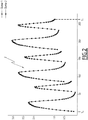
- Figure 2 shows a temporal series S of current samples obtained between a first instant T 0 and a second instant T F , forming a period of 270 ms, the horizontal axis showing the time (in milliseconds) and the vertical axis showing current values (in A for Ampere).
- the series S is actually composed of current samples from two types of pulses of different pulse widths.
- the clustering algorithm is applied by the health assessment system 6, an embodiment of which is shown in figure 1 .
- the health assessment system 6 is an electronic system comprising one or several Data Acquisition Units (DAU). In the example of figure 1 , the health assessment system 6 comprises two DAU 30, 32.
- DAU Data Acquisition Unit
- the DAU 30 is configured to collect current samples from the current sensor device 22 placed at the transmitting end of the track circuit. These current samples are called transmitted current samples.
- the DAU 32 is configured to collect current samples from the current sensor device 24 placed at the receiving end of the track circuit. These current samples are called received current samples.
- Each DAU 30, 32 comprises connectors through which the data exchange is performed, such as USB ("Universal Serial Bus”) connectors, radiofrequency connectors such as WIFI, Bluetooth or modems to connect to Internet.
- USB Universal Serial Bus
- WIFI Wireless Fidelity
- Bluetooth Wireless Fidelity
- the collected series of current samples are stored in a database 34.
- the health assessment system 6 further comprises a k-means clustering unit 36, a peak detector unit 38 and a health indicator computing unit 40.
- the k-means clustering unit 36, peak detector unit 38 and health indicator computing unit 40 are implemented as software, stored in a memory 42 of the health assessment electronic system 6, and executed by the processor 44.
- the units 36, 38 and 40 are stored on a non-volatile information recording medium, such as an optical disk, a magneto-optical disk, any type of non-volatile memory (e.g. EPROM, EEPROM, FLASH, NVRAM), a magnetic card or and optical card.
- a non-volatile information recording medium such as an optical disk, a magneto-optical disk, any type of non-volatile memory (e.g. EPROM, EEPROM, FLASH, NVRAM), a magnetic card or and optical card.
- each of the units 36, 38 and 40 is implemented by a FPGA (Field Programmable Gate Array), or a dedicated integrated circuit such as an ASIC (Applications Specific Integrated Circuit).
- FPGA Field Programmable Gate Array
- ASIC Applications Specific Integrated Circuit
- the health assessment electronic system 6 is configured to transmit the computed health indicators to a rail maintenance center 46.
- the transmission is carried out via radiofrequency connectors, using a wireless communication protocol.
- the health assessment electronic system 6 is situated within a rail maintenance center and the transmission is carried out by a wired connection.
- a health indicator of the track circuit is a parameter having a value representative of a level of degradation of the track circuit 4 or of a part of the track circuit 4, for example the track section 2.
- the computed health indicators are used to apply predictive maintenance, for example by recording successive values of each health indicator computed is it possible to accurately predict a track-circuit failure or a track section degradation before an actual failure, and to apply corrective measures to prevent failures.
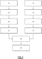
- Figure 3 shows steps of a method for health assessment of a track circuit according to an embodiment.
- a temporal series of current samples are obtained from a current sensor device placed near the receiving end.
- An analogous step 110 is carried out to obtain a temporal series of current samples from a current sensor device placed near the transmitting end.
- the samples are obtained from payload packets formatted according to a communication protocol, for example UDP ("User Datagram Protocol”) packets.
- UDP User Datagram Protocol
- Each UDP packet consists of 1 to 2 pulses, where each pulse consists of a number of temporal samples, for example, 43.
- the temporal series of samples is processed in feature extraction step 120 to obtain estimated pulse features.
- the processing comprises comparing each current sample value to a current threshold value. For example, for current samples comprised between 0 and 3.5 A, the threshold value is set to 1 A.
- the current sample values above the threshold are used to compute estimated peak amplitude (maximum value of samples above the threshold, for example, 2.3 A) and pulse width (number of samples above the threshold, for example, 20).
- One peak amplitude and one pulse width are computed for each pulse.
- train moves data is filtered out, based on a track occupancy flag provided by the track circuit software. For example, a flag with value 1 indicates that the track is occupied by train and a flag with 0 indicates that the track is not occupied.
- a feature extraction step 130 is carried to obtain estimated features from a temporal series of current samples from the current measuring sensor placed near the transmitting end.
- Step 120 (respectively 130) is followed by an automatic clustering step 140 (respectively 150), applied by the k-means clustering unit 36, to separate the received current samples into a predetermined number of clusters, each cluster corresponding to current samples of pulse of a same type.
- an automatic clustering step 140 (respectively 150), applied by the k-means clustering unit 36, to separate the received current samples into a predetermined number of clusters, each cluster corresponding to current samples of pulse of a same type.
- k-means clustering is applied, with a predetermined number of clusters K.
- the k-means algorithm comprises the following steps:
- the result of the automatic clustering is to obtain clusters of homogeneous samples.
- a peak current value is computed (step 160, 170) by peak detector unit 38.
- the peak current value is the maximum current sample value of all samples belonging to the selected cluster.
- the cluster with the smallest centroid value is chosen for the processing at the transmitting end and at the receiving end.
- the peak current value is computed (for example, the peak current value is around 2.75 A in the example of figure 2 ).
- One or several health indicators are computed by the health indicator computing unit 40 in next health indicator computing step 180.
- Ballast resistance is one of the indicators of the health condition of the track circuit computed in step 180.
- a low ballast resistance corresponds to a bad health condition, and a high ballast resistance corresponds to good health condition.
- low resistance and high resistance are defined for example from experimental data, collected from healthy track sections/track circuits, for example on a new material.
- R ballast TL ⁇ V tx + V rx 2 ⁇ 1000 ⁇ I tx ⁇ I rx
- TL is the track section length
- V rx is a first voltage value of the modulated electric signal at the receiving end
- V tx is a second voltage value of the modulated electric signal at the transmitting end
- I rx is the peak current value at the receiving end as computed in step 160
- I tx is the peak current value at the transmitting end as computed in step 170.
- V tx V s ⁇ I tx ⁇ R tx V
- V s the voltage of electric signal generator 20
- R tx the resistance of the wires connecting the track circuit and the rails at the transmitting end.
- V rx I rx ⁇ R rx V where R rx is the resistance of the wires connecting the track circuit and the rails at the receiving end.
- ballast resistance of a track circuit with the following parameters is 7.6 (Ohms/1000ft) -
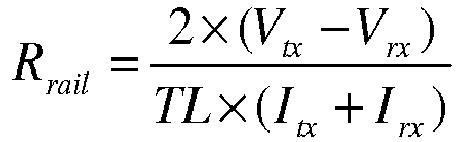
- Rail resistance is another one of the indicators of the health condition of the track circuit computed in step 180.
- An abnormal rail resistance might correspond to a broken rail condition.
- the "normal" rail resistance values are obtained for example from experimental data, collected from healthy/new track sections.
- R rail 2 ⁇ V tx ⁇ V rx TL ⁇ I tx + I rx
- the rail resistance of a track circuit with the following parameters is - 6.5E-06 (Ohms/ft) -
- either only the ballast resistance or only the rail resistance is computed.
- both the ballast resistance and the rail resistance are computed.
- the health indicator(s) are then processed in step 190, for example transmitted to a rail maintenance center and compared to recorded threshold values in order to detect problems and estimates risks of failure, and to apply predictive maintenance.
- the values of voltage and current at the transmitting end of the track circuit are previously stored, and only the values of the voltage and of the peak current amplitude are measured.
- the steps 100, 120, 140 and 160 are applied, whereas the peak current amplitude at the transmitting end is obtained from a memory of the health assessment system.
- the computed values S(k) can be plotted, and the chosen value for k is the value K for which the computed plot forms an elbow.
- computing the number of clusters can be applied each time the type of pulses transmitted is changed.
- the invention has been described in an embodiment using samples of current pulses of the electric signal transmitted between the transmitting end and the receiving end of the track section.
- the method for health assessment of a track circuit and/or a track section applies with samples of other electrical parameters of the electric signal transmitted between the transmitting end and the receiving end of the track section.
- the proposed method does not require building any reference on the features characterizing the pulses and can adapt automatically to changes in terms of pulse features.
- the proposed method achieves automatic clustering of samples belonging to pulses, and therefore the data sets used to compute health indicators are less noisy, and the health indicators computed are more reliable.
Landscapes
- Engineering & Computer Science (AREA)
- Mechanical Engineering (AREA)
- Automation & Control Theory (AREA)
- Physics & Mathematics (AREA)
- General Physics & Mathematics (AREA)
- Data Mining & Analysis (AREA)
- Theoretical Computer Science (AREA)
- Probability & Statistics with Applications (AREA)
- Artificial Intelligence (AREA)
- Bioinformatics & Cheminformatics (AREA)
- Bioinformatics & Computational Biology (AREA)
- Computer Vision & Pattern Recognition (AREA)
- Evolutionary Biology (AREA)
- Evolutionary Computation (AREA)
- General Engineering & Computer Science (AREA)
- Life Sciences & Earth Sciences (AREA)
- Architecture (AREA)
- Civil Engineering (AREA)
- Structural Engineering (AREA)
- Train Traffic Observation, Control, And Security (AREA)
Abstract
Description
- The present invention concerns a method and a system for health assessment of a track circuit and/or of a track section, the track circuit being designed for detecting the presence of a vehicle on the track section.
- The invention belongs to the field of railway operating and maintenance.
- It is known that detecting the presence of vehicles, in particular trains, on railway tracks is critical for railway signaling systems, and is therefore an important component of railway infrastructures security.
- Track circuits are designed for detecting the presence of vehicles, in particular trains, on tracks of a track section. A track circuit is an electrical circuit using tracks and relays, for transmitting DC electric signals from a first end, also called transmitting end of the track circuit to a second end, also called receiving end of the track circuit. When a train is present on a track section belonging to the track circuit, the wheels and the axle of the train induce a short-circuit, therefore no electric signal is received at the receiving end of the track circuit, indicating the presence of a train. Current sensor devices such as ammeters are installed on both ends of the track circuit to record the current values of the transmitted signal at the transmitting end and the received signal at the receiving end of the track circuit. The current values form samples of an electric signal. By extracting different information from the recorded sample values, it is possible to estimate the degradation/health condition of the railway track section or track circuit, and calculate the accuracy of train detection.
- It is known to transmit a modulated signal in the form of pulses with different pulse features in order to carry different information, which causes sample values of the pulses received at the receiving end to be heterogeneous. Furthermore, due to environment conditions and track degradation, the received pulses are also noisy.
- The received noisy and heterogeneous samples are not applicable for further data analysis, in particular cannot provide a reliable assessment of the track circuit health.
- There is a need to improve the track circuit health assessment.
- This and other objects are achieved by a method for health assessment of a track circuit and/or of a track section, the track circuit being configured for detecting the presence of a vehicle on the track section between a transmitting end and a receiving end of the track circuit, the method being implemented by an electronic device, and comprising:
- obtaining, from a sensor device placed near the receiving end, samples of an electrical parameter of an electric signal transmitted between the transmitting end and the receiving end of the track section, forming a temporal series of samples,
- applying an automatic clustering algorithm to separate the received samples in a predetermined number of clusters,
- selecting one of said clusters and determining, for the selected cluster, a first peak value of the received samples classified within the selected cluster, and
- computing a track circuit health indicator depending on the first peak value determined for the selected cluster.
- In embodiments of the invention, the method for health assessment of a track circuit comprises one or more of the following features, considered alone or according to all technically possible combinations.
- The method further comprises:
- obtaining, from a sensor device placed near the transmitting end, samples of the electrical parameter of the electric signal transmitted between the transmitting end and the receiving end of the track circuit, forming a temporal series of transmitted samples,
- applying the automatic clustering algorithm to separate the transmitted samples in a predetermined number of clusters,
- selecting one of said clusters and determining, for the selected cluster, a second peak value of the transmitted samples classified within the selected cluster, wherein the track circuit health indicator further depends on the second peak value.
- The automatic clustering algorithm applied is a k-means algorithm.
- The method further comprises, before applying the k-means algorithm, automatically computing a number K of clusters to use for classifying the temporal series of samples.
- The automatic clustering algorithm comprises computing a P-dimensional feature vector associated to each sample of the temporal series of samples.
- The automatic clustering algorithm further comprises:
- a) obtaining K centroids, each centroid being associated to a cluster,
- b) computing a distance between each feature vector and each centroid, and assigning the feature vector to a cluster associated to the closest centroid according to the distance computed;
- c) for each cluster, obtaining an updated centroid computed as a mean value of all feature vectors assigned to the cluster associated to the centroid,
- d) repeating steps b) and c) until a stop criterion is met.
- The method further comprises obtaining a first voltage value of the electric signal at the receiving end and a second voltage value of the electric signal at the transmitting end.
- The track circuit health indicator is a ballast resistance and/or a rail resistance.
- The electrical parameter is a current, the received samples are received current samples, the transmitted samples are transmitted current samples, the first peak value is a first peak current value and the second peak value is a second peak current value.
- The track circuit health indicator is a ballast resistance, expressed in Ohms per thousand feet and computed by the following formula:

- The track circuit health indicator is a rail resistance, expressed in Ohms per feet and computed by the following formula:
- The invention relates also to a system for health assessment of a track circuit and/or of a track section, the track circuit being configured for detecting the presence of a vehicle on the track section between a transmitting end and a receiving end of the track circuit, comprising an electronic device comprising at least one processor configured to :- obtain, from a sensor device placed near the receiving end, samples of an electrical parameter of an electric signal transmitted between the transmitting end and the receiving end of the track section, forming a temporal series of samples,
- apply an automatic clustering algorithm to separate the received samples in a predetermined number of clusters,
- select one of said clusters and determine, for the selected cluster, a first peak value of the received samples classified within the selected cluster, and
- compute a track circuit health indicator depending on the first peak value determined for the selected cluster.
- Further characteristics and advantages of the present invention will become apparent from the following description, provided merely by way of non-limiting example, with reference to the enclosed drawings, in which:
-
Figure 1 shows a track circuit with a corresponding track section and a system for health assessment according to an embodiment of the present invention; -
Figure 2 shows an example of a series of received current samples classified into two clusters; -
Figure 3 shows steps of a method for health assessment of a track circuit according to an embodiment of the present invention. -
Figure 1 illustrates schematically an example of atrack section 2 belonging to a track circuit 4, and ahealth assessment system 6 according to an embodiment of the invention. - The
track section 2 is a portion of a railway track, for example formed by twoparallel rails rails railway sleepers 8 placed onballast 10. - Classically, the
rails - The
track section 2 is comprised between a firstinsulating joint 12 and a secondinsulating joint 14. In the example shown, eachinsulating joint parallel rails - The first
insulating joint 12 defines a first end, also called transmitting end TE of the track circuit 4 and the secondinsulating joint 14 defines a second end, also called receiving end RE of the track circuit 4. - The track circuit 4 further comprises an electric signal generator and
modulator 20 schematically represented as a single unit, configured to generate, from a direct current (abbreviated as DC) electric signal power source, modulated electric signals, coded to carry information. The modulated electric signals are obtained by turning on and off a power generator at a given rate called modulation frequency, the purpose of modulation being to carry information. A modulated electric signal is formed by a series of pulses. - The pulses are characterized by several pulse features: pulse center frequency, pulse bandwidth, pulse duration or width, and time between pulses.
- In an embodiment, two different pulse widths are applied and therefore two types of pulses are generated, and transmitted.
- The electric signal generator and
modulator 20 is connected by two conducting branches to each conductingrail - The track circuit 4 may include switches and relays which are conventional and are not represented in the
figure 1 . - When there is no train on the
track section 2, an electric signal circulates in the circuit created by the connection of the generator andmodulator 20 to the conducting rails of the track section, between the firstinsulating joint 12 and the secondinsulating joint 14. A modulated electric signal transmitted from the transmitting end TE is received at the receiving end RE. - When a train is present of the
track section 2, the wheels and axle of the train achieve a short-circuit and no electric signal is received at the receiving end RE of the track circuit 4. - In order to measure the current amplitude, two
current sensor devices joints - Each current sensor device is configured to measure temporal series of current samples, corresponding respectively to the current values of the transmitted or received electrical pulses.
- In an embodiment, the modulated electric signal transmitted between the transmitting end and the receiving end of the track circuit is composed of several types of pulses generated with different pulse features.
- In some embodiments, the track circuit 4 includes several types of sensors such as current, voltage and power sensors. Each sensor device is configured to measure temporal series of current, voltage or power samples.
- Preferably, the sample values are captured during a period of given duration, for example, 2 seconds, and are in addition uniformly sampled (with minimal resolution of 1 ms) and ordered in the form of temporal series of samples values.
- Depending on the embodiments, the sampling and ordering operations are performed either by the measuring devices or in Data Acquisition Units (DAUs) 30, 32 of the health assessment system which in this case include an analogue-to-digital converter and a processor.
-
Figure 2 shows a temporal series S of current samples obtained between a first instant T0 and a second instant TF, forming a period of 270 ms, the horizontal axis showing the time (in milliseconds) and the vertical axis showing current values (in A for Ampere). - In the example, the series S is actually composed of current samples from two types of pulses of different pulse widths.
- It is proposed to apply a k-means clustering algorithm to automatically classify the current samples into two clusters, referenced Cluster 1 and
Cluster 2 in this example and indicated with a triangular reference for the samples belonging to Cluster 1 and a disk reference for the samples belonging toCluster 2. - The clustering algorithm is applied by the
health assessment system 6, an embodiment of which is shown infigure 1 . - The
health assessment system 6 is an electronic system comprising one or several Data Acquisition Units (DAU). In the example offigure 1 , thehealth assessment system 6 comprises twoDAU - The
DAU 30 is configured to collect current samples from thecurrent sensor device 22 placed at the transmitting end of the track circuit. These current samples are called transmitted current samples. - The
DAU 32 is configured to collect current samples from thecurrent sensor device 24 placed at the receiving end of the track circuit. These current samples are called received current samples. - Each
DAU - The collected series of current samples are stored in a
database 34. - The
health assessment system 6 further comprises a k-means clustering unit 36, apeak detector unit 38 and a healthindicator computing unit 40. - In an embodiment, the k-
means clustering unit 36,peak detector unit 38 and healthindicator computing unit 40 are implemented as software, stored in amemory 42 of the health assessmentelectronic system 6, and executed by theprocessor 44. Alternatively, theunits - In an alternative embodiment, each of the
units - The health assessment
electronic system 6 is configured to transmit the computed health indicators to arail maintenance center 46. In an embodiment, the transmission is carried out via radiofrequency connectors, using a wireless communication protocol. In a variant, the health assessmentelectronic system 6 is situated within a rail maintenance center and the transmission is carried out by a wired connection. - A health indicator of the track circuit is a parameter having a value representative of a level of degradation of the track circuit 4 or of a part of the track circuit 4, for example the
track section 2. - The computed health indicators are used to apply predictive maintenance, for example by recording successive values of each health indicator computed is it possible to accurately predict a track-circuit failure or a track section degradation before an actual failure, and to apply corrective measures to prevent failures.
-
Figure 3 shows steps of a method for health assessment of a track circuit according to an embodiment. - In the embodiment of
figure 3 , analogous steps, performed on temporal series of current samples from the transmitting end and from the receiving end, are shown. - In a
first step 100, a temporal series of current samples are obtained from a current sensor device placed near the receiving end. - An
analogous step 110 is carried out to obtain a temporal series of current samples from a current sensor device placed near the transmitting end. - For example, in an embodiment, the samples are obtained from payload packets formatted according to a communication protocol, for example UDP ("User Datagram Protocol") packets. Each UDP packet consists of 1 to 2 pulses, where each pulse consists of a number of temporal samples, for example, 43.
- Next, the temporal series of samples is processed in
feature extraction step 120 to obtain estimated pulse features. - The processing comprises comparing each current sample value to a current threshold value. For example, for current samples comprised between 0 and 3.5 A, the threshold value is set to 1 A.
- The current sample values above the threshold are used to compute estimated peak amplitude (maximum value of samples above the threshold, for example, 2.3 A) and pulse width (number of samples above the threshold, for example, 20). One peak amplitude and one pulse width are computed for each pulse. To carry out a clustering algorithm, we need a minimum of 1000 to 2000 pulses.
- In a variant, before estimating the pulse features, train moves data is filtered out, based on a track occupancy flag provided by the track circuit software. For example, a flag with value 1 indicates that the track is occupied by train and a flag with 0 indicates that the track is not occupied.
- A
feature extraction step 130, analogous to step 120, is carried to obtain estimated features from a temporal series of current samples from the current measuring sensor placed near the transmitting end. - Step 120 (respectively 130) is followed by an automatic clustering step 140 (respectively 150), applied by the k-
means clustering unit 36, to separate the received current samples into a predetermined number of clusters, each cluster corresponding to current samples of pulse of a same type. - In the preferred embodiment k-means clustering is applied, with a predetermined number of clusters K.
- The k-means clustering algorithm is applied on P-dimensional vectors of features, each vector of feature being associated with a current sample or a sub-group of current samples of the series of current samples, with P being a positive integer. For example, K=2 for 2 clusters.
- For example, in a first embodiment, only the estimated pulse width is used (P=1). In a second embodiment, the peak amplitude and the pulse width are used (P=2).
- The k-means algorithm comprises the following steps:
- a) Obtaining K centroids, which are for example randomly chosen at initializing. Each centroid is a P-dimensional vector of feature which is the center of an associated cluster;
- b) Each feature vector is assigned to the cluster associated to the centroid that is closest according to a predetermined distance. For example, Euclidean distance is used. Other distance metrics include Manhattan distance which is computed as absolute difference between coordinates of pair of objects.
- c) The mean vector of each cluster is updated after all samples are classified, so as to obtain K updated centroids;
- d) The steps b) and c) are repeated until the centroids positions converge in the P-dimensional space, and more generally until a stop criterion is met. For example, the stop criterion may be a predetermined number of iterations. In an alternative embodiment, the stop criterion may be ensuring that the distance in the P-dimensional space of two successive updated centroids associated to the same cluster is less than a given threshold.
- The result of the automatic clustering is to obtain clusters of homogeneous samples.
- Next, one of the clusters is selected, and a peak current value is computed (
step 160, 170) bypeak detector unit 38. The peak current value is the maximum current sample value of all samples belonging to the selected cluster. - For example, in an embodiment, the cluster with the smallest centroid value is chosen for the processing at the transmitting end and at the receiving end.
- Referring to
figure 2 , forexample Cluster 2 is selected, and the peak current value is computed (for example, the peak current value is around 2.75 A in the example offigure 2 ). - One or several health indicators are computed by the health
indicator computing unit 40 in next healthindicator computing step 180. - Ballast resistance is one of the indicators of the health condition of the track circuit computed in
step 180. A low ballast resistance corresponds to a bad health condition, and a high ballast resistance corresponds to good health condition. - The definition of "low resistance" and "high resistance" is obtained for example from experimental data, collected from healthy track sections/track circuits, for example on a new material.
- The ballast resistance, expressed in Ohms/1000 feet, is given by the formula:

step 160, and Itx , is the peak current value at the transmitting end as computed instep 170. - Vtx is given by the formula :

electric signal generator 20 and Rtx is the resistance of the wires connecting the track circuit and the rails at the transmitting end. - Vrx is given by the formula :

- For example, the ballast resistance of a track circuit with the following parameters is 7.6 (Ohms/1000ft) -
- TL = 9210 (feet),
- Vs =2.0 (V),
- Rtx = Rrx =0.53 (Ohms)
- Itx =2.46 (A)
- Irx =1.54 (A)
- Rail resistance is another one of the indicators of the health condition of the track circuit computed in
step 180. An abnormal rail resistance might correspond to a broken rail condition. The "normal" rail resistance values are obtained for example from experimental data, collected from healthy/new track sections. - The rail resistance, expressed in Ohms/feet, is given by the formula:

- For example, the rail resistance of a track circuit with the following parameters is - 6.5E-06 (Ohms/ft) -
- TL = 9210 (feet),
- Vs =2.0 (V),
- Rtx = Rrx =0.53 (Ohms)
- Itx =2.46 (A)
- Irx =1.54 (A)
- In an embodiment, either only the ballast resistance or only the rail resistance is computed. In a variant, both the ballast resistance and the rail resistance are computed.
- In another variant, further track circuit/track section health indicators are computed.
- The health indicator(s) are then processed in
step 190, for example transmitted to a rail maintenance center and compared to recorded threshold values in order to detect problems and estimates risks of failure, and to apply predictive maintenance. - In an alternative embodiment, the values of voltage and current at the transmitting end of the track circuit are previously stored, and only the values of the voltage and of the peak current amplitude are measured. In this alternative, only the
steps - In another alternative embodiment, the number K of clusters applied in the K-means clustering algorithm is not known in advance, but is estimated automatically. For example, several values for K are tested with P-dimensional vectors of features, for example k varying from 1 to 9, and the best K value is chosen based on the within-cluster sum of squares according to the formula:

- The computed values S(k) can be plotted, and the chosen value for k is the value K for which the computed plot forms an elbow.
- In particular, computing the number of clusters can be applied each time the type of pulses transmitted is changed.
- The invention has been described in an embodiment using samples of current pulses of the electric signal transmitted between the transmitting end and the receiving end of the track section. In alternative embodiments, the method for health assessment of a track circuit and/or a track section applies with samples of other electrical parameters of the electric signal transmitted between the transmitting end and the receiving end of the track section.
- Advantageously, the proposed method does not require building any reference on the features characterizing the pulses and can adapt automatically to changes in terms of pulse features.
- Advantageously, the proposed method achieves automatic clustering of samples belonging to pulses, and therefore the data sets used to compute health indicators are less noisy, and the health indicators computed are more reliable.
Claims (13)
- Method for health assessment of a track circuit and/or of a track section, the track circuit being configured for detecting the presence of a vehicle on the track section between a transmitting end and a receiving end of the track circuit, the transmitting end and the receiving end being associated to respective ends of the track section, the method being implemented by an electronic device, and being characterized in that it comprises:- obtaining (100), from a sensor device placed near the receiving end, samples of an electrical parameter of an electric signal transmitted between the transmitting end and the receiving end of the track circuit, forming a temporal series of samples,- applying (120, 140) an automatic clustering algorithm to separate the received samples in a predetermined number of clusters,- selecting (160) one of said clusters and determining, for the selected cluster, a first peak value of the received samples classified within the selected cluster, and- computing (180) a track circuit health indicator depending on the first peak value determined for the selected cluster.
- The method for health assessment according to claim 1, further comprising:- obtaining (110), from a sensor device placed near the transmitting end, samples of the electrical parameter of the electric signal transmitted between the transmitting end and the receiving end of the track circuit, forming a temporal series of transmitted samples,- applying (130, 510) the automatic clustering algorithm to separate the transmitted samples in a predetermined number of clusters,- selecting (170) one of said clusters and determining, for the selected cluster, a second peak value of the transmitted samples classified within the selected cluster, wherein the track circuit health indicator further depends on the second peak value.
- The method for health assessment according to claims 1 or 2, wherein the automatic clustering algorithm applied is a k-means algorithm.
- The method for health assessment according to claim 3, further comprising, before applying the k-means algorithm, automatically computing a number K of clusters to use for classifying the temporal series of samples.
- The method for health assessment according to claims 3 or 4, wherein the automatic clustering algorithm comprises:- computing a P-dimensional feature vector associated to each sample or sub-group of samples of the temporal series of samples.
- The method for health assessment according to claim 5, wherein the automatic clustering algorithm further comprises:- a) obtaining K centroids, each centroid being associated to a cluster,- b) computing a distance between each feature vector and each centroid, and assigning the feature vector to a cluster associated to the closest centroid according to the distance computed;- c) for each cluster, obtaining an updated centroid computed as a mean value of all feature vectors assigned to the cluster associated to the centroid,- d) repeating steps b) and c) until a stop criterion is met.
- The method for health assessment according to any of claims 1 to 6, further comprising obtaining a first voltage value of the electric signal at the receiving end and a second voltage value of the electric signal at the transmitting end.
- The method for health assessment according to claim 7, wherein the track circuit health indicator is a ballast resistance and/or a rail resistance.
- The method for health assessment according to claim 2, wherein the electrical parameter is a current, the received samples are received current samples, the transmitted samples are transmitted current samples, the first peak value is a first peak current value and the second peak value is a second peak current value.
- The method for health assessment according to claim 9, wherein the track circuit health indicator is either:- a ballast resistance, expressed in Ohms per thousand feet and computed by the following formula:
 - a rail resistance, expressed in Ohms per feet and computed by the following formula:
- System for health assessment of a track circuit and/or of a track section, the track circuit being configured for detecting the presence of a vehicle on the track section between a transmitting end and a receiving end of the track circuit, the transmitting end and the receiving end being associated to respective ends of the track section, characterized in that it comprises an electronic device comprising at least one processor configured to:- obtain (32), from a sensor device placed near the receiving end, samples of an electrical parameter of an electric signal transmitted between the transmitting end and the receiving end of the track circuit, forming a temporal series of samples,- apply (36) an automatic clustering algorithm to separate the received samples in a predetermined number of clusters,- select (38) one of said clusters and determine, for the selected cluster, a first peak value of the received samples classified within the selected cluster, and- compute (40) a track circuit health indicator depending on the first peak value determined for the selected cluster.
- The system for health assessment according claim 11, wherein the processor is further configured to:- obtain (30), from a sensor device placed near the transmitting end, samples of the electrical parameter of the electric signal transmitted between the transmitting end and the receiving end of the track circuit, forming a temporal series of transmitted samples,- apply (36) the automatic clustering algorithm to separate the transmitted samples in a predetermined number of clusters,- select (38) one of said clusters and determine, for the selected cluster, a second peak value of the transmitted samples classified within the selected cluster, wherein the track circuit health indicator further depends on the second peak value.
- The system for health assessment according to claim 12, wherein the electrical parameter is a current, the received samples are received current samples, the transmitted samples are transmitted current samples, the first peak value is a first peak current value and the second peak value is a second peak current value.
Applications Claiming Priority (1)
| Application Number | Priority Date | Filing Date | Title |
|---|---|---|---|
| US16/193,444 US11260888B2 (en) | 2018-11-16 | 2018-11-16 | Method and system for health assessment of a track circuit and/or of a track section |
Publications (2)
| Publication Number | Publication Date |
|---|---|
| EP3653465A1 true EP3653465A1 (en) | 2020-05-20 |
| EP3653465B1 EP3653465B1 (en) | 2021-04-21 |
Family
ID=68583112
Family Applications (1)
| Application Number | Title | Priority Date | Filing Date |
|---|---|---|---|
| EP19209320.1A Active EP3653465B1 (en) | 2018-11-16 | 2019-11-15 | Method and system for health assessment of a track circuit and/or of a track section |
Country Status (6)
| Country | Link |
|---|---|
| US (1) | US11260888B2 (en) |
| EP (1) | EP3653465B1 (en) |
| AU (1) | AU2019264513B2 (en) |
| CA (1) | CA3061523A1 (en) |
| ES (1) | ES2880503T3 (en) |
| MX (1) | MX2019013382A (en) |
Cited By (2)
| Publication number | Priority date | Publication date | Assignee | Title |
|---|---|---|---|---|
| CN112763242A (en) * | 2021-04-12 | 2021-05-07 | 西南交通大学 | Reliability evaluation test bed for rail state vehicle-mounted detection system |
| US20220185351A1 (en) * | 2020-12-15 | 2022-06-16 | Alstom Transport Technologies | Method, system, computer-readable medium comprising software code for estimating parameters of railway track circuits, and related track circuit |
Families Citing this family (5)
| Publication number | Priority date | Publication date | Assignee | Title |
|---|---|---|---|---|
| US11577763B2 (en) * | 2020-03-06 | 2023-02-14 | Alstom Transport Technologies | Method and controller for determining the relationship between a track-circuit transmitted current signal and a railway vehicle location on a railway track |
| JP7538726B2 (en) * | 2021-01-15 | 2024-08-22 | 株式会社鷺宮製作所 | Track Circuit Monitoring Device |
| US12466451B2 (en) * | 2021-09-24 | 2025-11-11 | Kb Signaling Inc. | Method and system for estimating temperature-related forces in railway lines |
| CN114834502B (en) * | 2022-05-25 | 2024-03-19 | 东莞灵虎智能科技有限公司 | Task rail break risk prediction method based on artificial intelligence and big data |
| CN116628446B (en) * | 2023-05-24 | 2024-10-29 | 成都工业职业技术学院 | Intelligent analysis method and system for turnout health standard value based on clustering algorithm |
Citations (4)
| Publication number | Priority date | Publication date | Assignee | Title |
|---|---|---|---|---|
| WO2008052643A2 (en) * | 2006-10-30 | 2008-05-08 | Siemens Schweiz Ag | Method and device for evaluation of measurement data in railway track circuits |
| WO2017197423A1 (en) * | 2016-05-17 | 2017-11-23 | Materials Center Leoben Forschung Gmbh | Method and device for monitoring at least one travel path component laid in rail construction |
| WO2018050502A1 (en) * | 2016-09-19 | 2018-03-22 | Siemens Aktiengesellschaft | Monitoring infrastructure facilities by means of geo-clustering |
| CN108099952A (en) * | 2017-11-13 | 2018-06-01 | 北京全路通信信号研究设计院集团有限公司 | Track circuit for signal separation and implementation method |
Family Cites Families (8)
| Publication number | Priority date | Publication date | Assignee | Title |
|---|---|---|---|---|
| US3870952A (en) * | 1973-07-16 | 1975-03-11 | Gen Signal Corp | Ballast resistance and track continuity indicating circuit |
| US5769364A (en) * | 1997-05-14 | 1998-06-23 | Harmon Industries, Inc. | Coded track circuit with diagnostic capability |
| US7502971B2 (en) * | 2005-10-12 | 2009-03-10 | Hewlett-Packard Development Company, L.P. | Determining a recurrent problem of a computer resource using signatures |
| US9989414B2 (en) * | 2013-03-29 | 2018-06-05 | Agilent Technologies, Inc. | Noise reduction for pulsed lasers using clustering |
| CN107530016A (en) * | 2015-04-20 | 2018-01-02 | 深圳市长桑技术有限公司 | A kind of physiology sign information acquisition methods and system |
| US10707975B2 (en) * | 2015-04-20 | 2020-07-07 | University Of Notre Dame Du Lac | Use of coherent signal dispersion for signal source association |
| US20170286838A1 (en) * | 2016-03-29 | 2017-10-05 | International Business Machines Corporation | Predicting solar power generation using semi-supervised learning |
| US10796190B2 (en) * | 2017-08-10 | 2020-10-06 | Massachusetts Institute Of Technology | Methods and apparatus for imaging of layers |
-
2018
- 2018-11-16 US US16/193,444 patent/US11260888B2/en active Active
-
2019
- 2019-11-08 MX MX2019013382A patent/MX2019013382A/en unknown
- 2019-11-11 AU AU2019264513A patent/AU2019264513B2/en active Active
- 2019-11-12 CA CA3061523A patent/CA3061523A1/en active Pending
- 2019-11-15 ES ES19209320T patent/ES2880503T3/en active Active
- 2019-11-15 EP EP19209320.1A patent/EP3653465B1/en active Active
Patent Citations (4)
| Publication number | Priority date | Publication date | Assignee | Title |
|---|---|---|---|---|
| WO2008052643A2 (en) * | 2006-10-30 | 2008-05-08 | Siemens Schweiz Ag | Method and device for evaluation of measurement data in railway track circuits |
| WO2017197423A1 (en) * | 2016-05-17 | 2017-11-23 | Materials Center Leoben Forschung Gmbh | Method and device for monitoring at least one travel path component laid in rail construction |
| WO2018050502A1 (en) * | 2016-09-19 | 2018-03-22 | Siemens Aktiengesellschaft | Monitoring infrastructure facilities by means of geo-clustering |
| CN108099952A (en) * | 2017-11-13 | 2018-06-01 | 北京全路通信信号研究设计院集团有限公司 | Track circuit for signal separation and implementation method |
Non-Patent Citations (1)
| Title |
|---|
| "Thesis", 28 September 2015, TU DELFT, Delft, article W P VERBEEK: "Delft Center for Systems and Control Condition monitoring for track circuits A multiple-model approach", pages: 1 - 101, XP055678442 * |
Cited By (4)
| Publication number | Priority date | Publication date | Assignee | Title |
|---|---|---|---|---|
| US20220185351A1 (en) * | 2020-12-15 | 2022-06-16 | Alstom Transport Technologies | Method, system, computer-readable medium comprising software code for estimating parameters of railway track circuits, and related track circuit |
| US11912322B2 (en) * | 2020-12-15 | 2024-02-27 | Alstom Transport Technologies | Method, system, computer-readable medium comprising software code for estimating parameters of railway track circuits, and related track circuit |
| CN112763242A (en) * | 2021-04-12 | 2021-05-07 | 西南交通大学 | Reliability evaluation test bed for rail state vehicle-mounted detection system |
| CN112763242B (en) * | 2021-04-12 | 2021-06-29 | 西南交通大学 | Reliability evaluation test bed for rail state vehicle-mounted detection system |
Also Published As
| Publication number | Publication date |
|---|---|
| AU2019264513A1 (en) | 2020-06-04 |
| US11260888B2 (en) | 2022-03-01 |
| ES2880503T3 (en) | 2021-11-24 |
| EP3653465B1 (en) | 2021-04-21 |
| US20200156674A1 (en) | 2020-05-21 |
| MX2019013382A (en) | 2020-08-31 |
| AU2019264513B2 (en) | 2023-01-05 |
| CA3061523A1 (en) | 2020-05-16 |
| BR102019023989A2 (en) | 2020-06-02 |
Similar Documents
| Publication | Publication Date | Title |
|---|---|---|
| EP3653465B1 (en) | Method and system for health assessment of a track circuit and/or of a track section | |
| KR101874286B1 (en) | Monitoring and diagnosis system for Power devices | |
| CN106093698B (en) | A traveling wave fault location method based on multi-measurement information | |
| US5680054A (en) | Broken rail position detection using ballast electrical property measurement | |
| US20110012586A1 (en) | Method for detecting, identifying and locating partial discharges occurring in a discharge site along an electric apparatus | |
| CN105372442A (en) | Train speed measuring method, processor and train speed measuring system | |
| US11186304B2 (en) | Method and electronic system for detecting rail switch degradation and failures | |
| US6924648B2 (en) | Method for identifying risks as a result of stray currents | |
| US11702119B2 (en) | Method for determining a status of a track section of a railroad; associated apparatus and non-transitory computer readable medium | |
| KR101579896B1 (en) | System and Method for Analyzing Cable State using Multi Band Signal | |
| CN118494559A (en) | Railway signal monitoring alarm system | |
| EP3563163B1 (en) | Travelling wave based method for locating a fault in a transmission line and device therefor | |
| CA2944463C (en) | Train direction detection apparatus and method | |
| CN117360589B (en) | Positive line code monitoring system and detection method based on in-station track railway | |
| JP6882909B2 (en) | Diagnostic system and diagnostic method | |
| KR102146924B1 (en) | System and method for measuring the status information of the feeder cable in the tunnel section | |
| CN108369254B (en) | Method of locating a fault in a power transmission medium | |
| CN110687401B (en) | Railway contact network fault detection system and method | |
| CN114674458A (en) | A temperature detection method, device, system and server for a maglev train | |
| EP4045378A1 (en) | Broken rail detector | |
| JP2021172271A (en) | Track circuit monitoring device and track circuit monitoring method | |
| BR102019023989B1 (en) | METHOD AND SYSTEM FOR ASSESSING THE HEALTH OF A ROAD CIRCUIT AND/OR A ROAD SECTION | |
| JP6662814B2 (en) | Track circuit monitoring device | |
| JPH0862277A (en) | Transmission line fault locator | |
| Augutis et al. | Measurements and processing of signals used in a cab signaling system |
Legal Events
| Date | Code | Title | Description |
|---|---|---|---|
| PUAI | Public reference made under article 153(3) epc to a published international application that has entered the european phase |
Free format text: ORIGINAL CODE: 0009012 |
|
| STAA | Information on the status of an ep patent application or granted ep patent |
Free format text: STATUS: THE APPLICATION HAS BEEN PUBLISHED |
|
| STAA | Information on the status of an ep patent application or granted ep patent |
Free format text: STATUS: REQUEST FOR EXAMINATION WAS MADE |
|
| AK | Designated contracting states |
Kind code of ref document: A1 Designated state(s): AL AT BE BG CH CY CZ DE DK EE ES FI FR GB GR HR HU IE IS IT LI LT LU LV MC MK MT NL NO PL PT RO RS SE SI SK SM TR |
|
| AX | Request for extension of the european patent |
Extension state: BA ME |
|
| 17P | Request for examination filed |
Effective date: 20200513 |
|
| RBV | Designated contracting states (corrected) |
Designated state(s): AL AT BE BG CH CY CZ DE DK EE ES FI FR GB GR HR HU IE IS IT LI LT LU LV MC MK MT NL NO PL PT RO RS SE SI SK SM TR |
|
| GRAP | Despatch of communication of intention to grant a patent |
Free format text: ORIGINAL CODE: EPIDOSNIGR1 |
|
| STAA | Information on the status of an ep patent application or granted ep patent |
Free format text: STATUS: GRANT OF PATENT IS INTENDED |
|
| INTG | Intention to grant announced |
Effective date: 20201201 |
|
| RIN1 | Information on inventor provided before grant (corrected) |
Inventor name: FRIES, JEFFREY Inventor name: QIN, SONG Inventor name: MIJATOVIC, NENAD |
|
| GRAS | Grant fee paid |
Free format text: ORIGINAL CODE: EPIDOSNIGR3 |
|
| GRAA | (expected) grant |
Free format text: ORIGINAL CODE: 0009210 |
|
| STAA | Information on the status of an ep patent application or granted ep patent |
Free format text: STATUS: THE PATENT HAS BEEN GRANTED |
|
| AK | Designated contracting states |
Kind code of ref document: B1 Designated state(s): AL AT BE BG CH CY CZ DE DK EE ES FI FR GB GR HR HU IE IS IT LI LT LU LV MC MK MT NL NO PL PT RO RS SE SI SK SM TR |
|
| REG | Reference to a national code |
Ref country code: GB Ref legal event code: FG4D |
|
| REG | Reference to a national code |
Ref country code: CH Ref legal event code: EP |
|
| REG | Reference to a national code |
Ref country code: DE Ref legal event code: R096 Ref document number: 602019004073 Country of ref document: DE Ref country code: IE Ref legal event code: FG4D |
|
| REG | Reference to a national code |
Ref country code: AT Ref legal event code: REF Ref document number: 1384336 Country of ref document: AT Kind code of ref document: T Effective date: 20210515 |
|
| REG | Reference to a national code |
Ref country code: SE Ref legal event code: TRGR |
|
| REG | Reference to a national code |
Ref country code: LT Ref legal event code: MG9D |
|
| REG | Reference to a national code |
Ref country code: AT Ref legal event code: MK05 Ref document number: 1384336 Country of ref document: AT Kind code of ref document: T Effective date: 20210421 |
|
| REG | Reference to a national code |
Ref country code: NL Ref legal event code: MP Effective date: 20210421 |
|
| PG25 | Lapsed in a contracting state [announced via postgrant information from national office to epo] |
Ref country code: FI Free format text: LAPSE BECAUSE OF FAILURE TO SUBMIT A TRANSLATION OF THE DESCRIPTION OR TO PAY THE FEE WITHIN THE PRESCRIBED TIME-LIMIT Effective date: 20210421 Ref country code: LT Free format text: LAPSE BECAUSE OF FAILURE TO SUBMIT A TRANSLATION OF THE DESCRIPTION OR TO PAY THE FEE WITHIN THE PRESCRIBED TIME-LIMIT Effective date: 20210421 Ref country code: HR Free format text: LAPSE BECAUSE OF FAILURE TO SUBMIT A TRANSLATION OF THE DESCRIPTION OR TO PAY THE FEE WITHIN THE PRESCRIBED TIME-LIMIT Effective date: 20210421 Ref country code: NL Free format text: LAPSE BECAUSE OF FAILURE TO SUBMIT A TRANSLATION OF THE DESCRIPTION OR TO PAY THE FEE WITHIN THE PRESCRIBED TIME-LIMIT Effective date: 20210421 Ref country code: BG Free format text: LAPSE BECAUSE OF FAILURE TO SUBMIT A TRANSLATION OF THE DESCRIPTION OR TO PAY THE FEE WITHIN THE PRESCRIBED TIME-LIMIT Effective date: 20210721 Ref country code: AT Free format text: LAPSE BECAUSE OF FAILURE TO SUBMIT A TRANSLATION OF THE DESCRIPTION OR TO PAY THE FEE WITHIN THE PRESCRIBED TIME-LIMIT Effective date: 20210421 |
|
| REG | Reference to a national code |
Ref country code: ES Ref legal event code: FG2A Ref document number: 2880503 Country of ref document: ES Kind code of ref document: T3 Effective date: 20211124 |
|
| PG25 | Lapsed in a contracting state [announced via postgrant information from national office to epo] |
Ref country code: IS Free format text: LAPSE BECAUSE OF FAILURE TO SUBMIT A TRANSLATION OF THE DESCRIPTION OR TO PAY THE FEE WITHIN THE PRESCRIBED TIME-LIMIT Effective date: 20210821 Ref country code: GR Free format text: LAPSE BECAUSE OF FAILURE TO SUBMIT A TRANSLATION OF THE DESCRIPTION OR TO PAY THE FEE WITHIN THE PRESCRIBED TIME-LIMIT Effective date: 20210722 Ref country code: PT Free format text: LAPSE BECAUSE OF FAILURE TO SUBMIT A TRANSLATION OF THE DESCRIPTION OR TO PAY THE FEE WITHIN THE PRESCRIBED TIME-LIMIT Effective date: 20210823 Ref country code: RS Free format text: LAPSE BECAUSE OF FAILURE TO SUBMIT A TRANSLATION OF THE DESCRIPTION OR TO PAY THE FEE WITHIN THE PRESCRIBED TIME-LIMIT Effective date: 20210421 Ref country code: PL Free format text: LAPSE BECAUSE OF FAILURE TO SUBMIT A TRANSLATION OF THE DESCRIPTION OR TO PAY THE FEE WITHIN THE PRESCRIBED TIME-LIMIT Effective date: 20210421 Ref country code: LV Free format text: LAPSE BECAUSE OF FAILURE TO SUBMIT A TRANSLATION OF THE DESCRIPTION OR TO PAY THE FEE WITHIN THE PRESCRIBED TIME-LIMIT Effective date: 20210421 Ref country code: NO Free format text: LAPSE BECAUSE OF FAILURE TO SUBMIT A TRANSLATION OF THE DESCRIPTION OR TO PAY THE FEE WITHIN THE PRESCRIBED TIME-LIMIT Effective date: 20210721 |
|
| REG | Reference to a national code |
Ref country code: DE Ref legal event code: R097 Ref document number: 602019004073 Country of ref document: DE |
|
| PG25 | Lapsed in a contracting state [announced via postgrant information from national office to epo] |
Ref country code: SK Free format text: LAPSE BECAUSE OF FAILURE TO SUBMIT A TRANSLATION OF THE DESCRIPTION OR TO PAY THE FEE WITHIN THE PRESCRIBED TIME-LIMIT Effective date: 20210421 Ref country code: EE Free format text: LAPSE BECAUSE OF FAILURE TO SUBMIT A TRANSLATION OF THE DESCRIPTION OR TO PAY THE FEE WITHIN THE PRESCRIBED TIME-LIMIT Effective date: 20210421 Ref country code: CZ Free format text: LAPSE BECAUSE OF FAILURE TO SUBMIT A TRANSLATION OF THE DESCRIPTION OR TO PAY THE FEE WITHIN THE PRESCRIBED TIME-LIMIT Effective date: 20210421 Ref country code: DK Free format text: LAPSE BECAUSE OF FAILURE TO SUBMIT A TRANSLATION OF THE DESCRIPTION OR TO PAY THE FEE WITHIN THE PRESCRIBED TIME-LIMIT Effective date: 20210421 Ref country code: RO Free format text: LAPSE BECAUSE OF FAILURE TO SUBMIT A TRANSLATION OF THE DESCRIPTION OR TO PAY THE FEE WITHIN THE PRESCRIBED TIME-LIMIT Effective date: 20210421 Ref country code: SM Free format text: LAPSE BECAUSE OF FAILURE TO SUBMIT A TRANSLATION OF THE DESCRIPTION OR TO PAY THE FEE WITHIN THE PRESCRIBED TIME-LIMIT Effective date: 20210421 |
|
| PLBE | No opposition filed within time limit |
Free format text: ORIGINAL CODE: 0009261 |
|
| STAA | Information on the status of an ep patent application or granted ep patent |
Free format text: STATUS: NO OPPOSITION FILED WITHIN TIME LIMIT |
|
| 26N | No opposition filed |
Effective date: 20220124 |
|
| PG25 | Lapsed in a contracting state [announced via postgrant information from national office to epo] |
Ref country code: IS Free format text: LAPSE BECAUSE OF FAILURE TO SUBMIT A TRANSLATION OF THE DESCRIPTION OR TO PAY THE FEE WITHIN THE PRESCRIBED TIME-LIMIT Effective date: 20210821 Ref country code: AL Free format text: LAPSE BECAUSE OF FAILURE TO SUBMIT A TRANSLATION OF THE DESCRIPTION OR TO PAY THE FEE WITHIN THE PRESCRIBED TIME-LIMIT Effective date: 20210421 |
|
| PG25 | Lapsed in a contracting state [announced via postgrant information from national office to epo] |
Ref country code: MC Free format text: LAPSE BECAUSE OF FAILURE TO SUBMIT A TRANSLATION OF THE DESCRIPTION OR TO PAY THE FEE WITHIN THE PRESCRIBED TIME-LIMIT Effective date: 20210421 |
|
| PG25 | Lapsed in a contracting state [announced via postgrant information from national office to epo] |
Ref country code: LU Free format text: LAPSE BECAUSE OF NON-PAYMENT OF DUE FEES Effective date: 20211115 |
|
| PG25 | Lapsed in a contracting state [announced via postgrant information from national office to epo] |
Ref country code: IE Free format text: LAPSE BECAUSE OF NON-PAYMENT OF DUE FEES Effective date: 20211115 |
|
| PG25 | Lapsed in a contracting state [announced via postgrant information from national office to epo] |
Ref country code: CY Free format text: LAPSE BECAUSE OF FAILURE TO SUBMIT A TRANSLATION OF THE DESCRIPTION OR TO PAY THE FEE WITHIN THE PRESCRIBED TIME-LIMIT Effective date: 20210421 |
|
| REG | Reference to a national code |
Ref country code: CH Ref legal event code: PL |
|
| PG25 | Lapsed in a contracting state [announced via postgrant information from national office to epo] |
Ref country code: LI Free format text: LAPSE BECAUSE OF NON-PAYMENT OF DUE FEES Effective date: 20221130 Ref country code: HU Free format text: LAPSE BECAUSE OF FAILURE TO SUBMIT A TRANSLATION OF THE DESCRIPTION OR TO PAY THE FEE WITHIN THE PRESCRIBED TIME-LIMIT; INVALID AB INITIO Effective date: 20191115 Ref country code: CH Free format text: LAPSE BECAUSE OF NON-PAYMENT OF DUE FEES Effective date: 20221130 |
|
| P01 | Opt-out of the competence of the unified patent court (upc) registered |
Effective date: 20230823 |
|
| PG25 | Lapsed in a contracting state [announced via postgrant information from national office to epo] |
Ref country code: MK Free format text: LAPSE BECAUSE OF FAILURE TO SUBMIT A TRANSLATION OF THE DESCRIPTION OR TO PAY THE FEE WITHIN THE PRESCRIBED TIME-LIMIT Effective date: 20210421 |
|
| REG | Reference to a national code |
Ref country code: DE Ref legal event code: R082 Ref document number: 602019004073 Country of ref document: DE Representative=s name: DENNEMEYER & ASSOCIATES S.A., DE Ref country code: DE Ref legal event code: R081 Ref document number: 602019004073 Country of ref document: DE Owner name: ALSTOM HOLDINGS, FR Free format text: FORMER OWNER: ALSTOM TRANSPORT TECHNOLOGIES, SAINT-OUEN, FR Ref country code: DE Ref legal event code: R082 Ref document number: 602019004073 Country of ref document: DE Representative=s name: DENNEMEYER & ASSOCIATES RECHTSANWALTSGESELLSCH, DE |
|
| PG25 | Lapsed in a contracting state [announced via postgrant information from national office to epo] |
Ref country code: MT Free format text: LAPSE BECAUSE OF FAILURE TO SUBMIT A TRANSLATION OF THE DESCRIPTION OR TO PAY THE FEE WITHIN THE PRESCRIBED TIME-LIMIT Effective date: 20210421 |
|
| REG | Reference to a national code |
Ref country code: GB Ref legal event code: 732E Free format text: REGISTERED BETWEEN 20250213 AND 20250219 |
|
| REG | Reference to a national code |
Ref country code: ES Ref legal event code: PC2A Owner name: ALSTOM HOLDINGS Effective date: 20250310 |
|
| REG | Reference to a national code |
Ref country code: BE Ref legal event code: PD Owner name: ALSTOM HOLDINGS; FR Free format text: DETAILS ASSIGNMENT: CHANGE OF OWNER(S), ASSIGNMENT; FORMER OWNER NAME: ALSTOM TRANSPORT TECHNOLOGIES Effective date: 20250204 Ref country code: BE Ref legal event code: PD Owner name: ALSTOM HOLDINGS; FR Free format text: DETAILS ASSIGNMENT: CHANGE OF OWNER(S), ASSIGNMENT Effective date: 20240812 |
|
| REG | Reference to a national code |
Ref country code: DE Ref legal event code: R082 Ref document number: 602019004073 Country of ref document: DE Representative=s name: DENNEMEYER & ASSOCIATES RECHTSANWALTSGESELLSCH, DE |
|
| PG25 | Lapsed in a contracting state [announced via postgrant information from national office to epo] |
Ref country code: TR Free format text: LAPSE BECAUSE OF FAILURE TO SUBMIT A TRANSLATION OF THE DESCRIPTION OR TO PAY THE FEE WITHIN THE PRESCRIBED TIME-LIMIT Effective date: 20210421 |
|
| PGFP | Annual fee paid to national office [announced via postgrant information from national office to epo] |
Ref country code: DE Payment date: 20251126 Year of fee payment: 7 |
|
| PGFP | Annual fee paid to national office [announced via postgrant information from national office to epo] |
Ref country code: GB Payment date: 20251125 Year of fee payment: 7 |
|
| PGFP | Annual fee paid to national office [announced via postgrant information from national office to epo] |
Ref country code: IT Payment date: 20251121 Year of fee payment: 7 |
|
| PGFP | Annual fee paid to national office [announced via postgrant information from national office to epo] |
Ref country code: FR Payment date: 20251124 Year of fee payment: 7 |
|
| PGFP | Annual fee paid to national office [announced via postgrant information from national office to epo] |
Ref country code: BE Payment date: 20251124 Year of fee payment: 7 |
|
| PGFP | Annual fee paid to national office [announced via postgrant information from national office to epo] |
Ref country code: SE Payment date: 20251124 Year of fee payment: 7 |
|
| PGFP | Annual fee paid to national office [announced via postgrant information from national office to epo] |
Ref country code: ES Payment date: 20251209 Year of fee payment: 7 |