EP3653442A1 - Actuator for an electric folding rear-view mirror for motor vehicles - Google Patents
Actuator for an electric folding rear-view mirror for motor vehicles Download PDFInfo
- Publication number
- EP3653442A1 EP3653442A1 EP18382810.2A EP18382810A EP3653442A1 EP 3653442 A1 EP3653442 A1 EP 3653442A1 EP 18382810 A EP18382810 A EP 18382810A EP 3653442 A1 EP3653442 A1 EP 3653442A1
- Authority
- EP
- European Patent Office
- Prior art keywords
- ramps
- motor housing
- support base
- gearwheel
- actuator
- Prior art date
- Legal status (The legal status is an assumption and is not a legal conclusion. Google has not performed a legal analysis and makes no representation as to the accuracy of the status listed.)
- Granted
Links
- 230000006835 compression Effects 0.000 description 3
- 238000007906 compression Methods 0.000 description 3
- 230000002411 adverse Effects 0.000 description 1
- 230000000712 assembly Effects 0.000 description 1
- 238000000429 assembly Methods 0.000 description 1
- 230000001419 dependent effect Effects 0.000 description 1
- 230000000694 effects Effects 0.000 description 1
- 238000004519 manufacturing process Methods 0.000 description 1
- 230000004048 modification Effects 0.000 description 1
- 238000012986 modification Methods 0.000 description 1
Images


Classifications
-
- B—PERFORMING OPERATIONS; TRANSPORTING
- B60—VEHICLES IN GENERAL
- B60R—VEHICLES, VEHICLE FITTINGS, OR VEHICLE PARTS, NOT OTHERWISE PROVIDED FOR
- B60R1/00—Optical viewing arrangements; Real-time viewing arrangements for drivers or passengers using optical image capturing systems, e.g. cameras or video systems specially adapted for use in or on vehicles
- B60R1/02—Rear-view mirror arrangements
- B60R1/06—Rear-view mirror arrangements mounted on vehicle exterior
- B60R1/062—Rear-view mirror arrangements mounted on vehicle exterior with remote control for adjusting position
- B60R1/07—Rear-view mirror arrangements mounted on vehicle exterior with remote control for adjusting position by electrically powered actuators
- B60R1/074—Rear-view mirror arrangements mounted on vehicle exterior with remote control for adjusting position by electrically powered actuators for retracting the mirror arrangements to a non-use position alongside the vehicle
Definitions
- the present disclosure relates to folding rear-view mirrors for motor vehicles and more specifically to actuators for driving such folding rear-view mirrors from an unfolded or operating position, where the mirror is substantially transverse to the vehicle body, into a folded or parking position, where the mirror is aligned substantially lengthwise with the vehicle body, and vice versa.
- Powered outside rear-view mirrors in motor vehicles are known in the art. They include electric drive means for driving a mirror housing with the rear-view mirror assembly in rotation to arrange the rear-view mirror from an unfolded or operating position, where the mirror is substantially transverse to the vehicle body, into a folded or parking position, where the mirror is aligned substantially lengthwise with the vehicle body, and vice versa, as required by circumstances or needs such as for example when the vehicle is running or when it is parked.
- the mirror housing is configured to be lifted up to the support base as it is driven in rotation by the electric drive means.
- one main problem in known rear-view mirrors still relates to annoying vibrations and noise in operation due to manufacturing tolerances resulting from clearances between moving parts of the mirror assembly combined with the weight of current mirror assemblies. Such vibrations and noise in known folding rear-view mirror when the vehicle is moving adversely affect motor vehicle driving comfort.
- seal based solutions have been supplemented by a mechanism capable of displacing, i.e. moving away from and/or closer to, the rear-view mirror housing relative to a base element that is mounted to the motor vehicle when the mirror housing is driven to be rotated.
- the mirror housing and the base element are snugly fitted together and can be moved away from each other when the mirror is being rotated into the folded position.
- a series of wedges or ramps is provided having an inclination designed for properly moving away from or closer both elements together as they are rotated to each other.
- US2014347755 discloses a folding rear-view mirror for motor vehicles that comprises a base member to be fixed to a vehicle, a housing for holding a rear-view mirror, a motor component to rotate the rear-view housing to the base member, and first and second sets of ramps independent of each other arranged to slide on corresponding fixed ramps of the base element and first and second resilient elements.
- the ramps of the first and second sets have different inclinations and the resilient elements have different spring rates from one another, depending on whether the mirror housing is manually or motor driven.
- US2018178728 also describes a folding rear-view mirror for motor vehicles that comprises a base to be fixed to a vehicle, a mirror housing, a motor housing for receiving a motor to rotate the mirror housing to the base and a connecting piece for manually rotating the motor housing to the base.
- a cam assembly is provided between the connecting piece and the base such that during mirror power folding, the cam assembly enables the mirror housing to lift up and rotate.
- the present rear-view mirror actuator comprises a support base.
- the support base is intended to be mounted on, usually fixed to, a motor vehicle and includes first and fourth set of ramps.
- the present rear-view mirror actuator further includes a motor assembly that comprises a motor housing.
- the first set of ramps of the support base may be arranged in an inner portion thereof and the fourth set of ramps of the support base may be arranged in an outer portion thereof.
- the first and fourth set of ramps of the support base are arranged concentrically to each other.
- a gearwheel is attached to the support base and arranged to rotate together with the motor housing when driven manually relative to the support base between a first angular position and a second angular position.
- the gearwheel is attached to the support base. In this case, only the motor housing together with the electric motor move around the gearwheel.
- the gearwheel includes a second set of ramps whose inclination is adapted for manual rotation of the motor housing relative to the support base.
- the second set of ramps engage the first set of ramps of the support base.
- the gearwheel comprises an axial upper end and an axial lower end.
- the motor housing includes a third set of ramps whose inclination is equal to or less than that of the second set of ramps of the gearwheel for power rotation of the motor housing relative to the support base.
- the third set of ramps engage the fourth set of ramps of the support base.
- the first, second, third, and fourth sets of ramps are arranged so that they can be moved relative to each other. Some of said sets of ramps are arranged so that they can slide independently at different times on each other. This may apply for example to all the sets of ramps except for those sets of ramps in the same part such as the first and fourth set of ramps of the support base.
- the fourth set of ramps of the support base are arranged to act on the third set of ramps of the motor housing to lift up the motor housing.
- the motor housing and the mirror housing are attached to one another so they are thus lifted up together, as the motor housing is driven by an electric motor fitted within the motor housing.
- the second set of ramps of the gearwheel is attached to the first set of ramps of the support base, while when the motor housing is rotated manually the gearwheel rotates together with the motor housing since they are attached to one another through the electric motor.
- the gearwheel is arranged to rest on the motor housing, but in certain cases directly on the support base.
- the support base and the motor housing are arranged such that, under a given angular position of the motor housing relative the support base, the first set of ramps of the support base contact the second set of ramps of the gearwheel but the gearwheel does not contact the motor housing.
- a given angular position refers to any angular position of the motor housing relative the support base, for example the first angular position, the second angular position, or any intermediate position between the first and second angular positions.
- said given angular position may correspond to a mirror unfolded or operating position where the mirror housing is arranged substantially transverse to the vehicle body, for driving. In that position, since the gearwheel does not contact the motor housing but contacts the support base directly the motor housing vibrations and therefore the mirror housing vibrations are advantageously avoided.
- one of the fourth set of ramps of the support base and the third set of ramps of the motor housing is configured to drive the motor housing towards or away from the support base as the motor assembly is operated.
- the first set of ramps of the support base and the second set of ramps of the gearwheel are configured such that the gearwheel contacts the support base in said given angular position of the motor housing relative to the support base, with the motor assembly gearwheel not contacting the motor housing. In that case, there is no clearance between the support base and the gearwheel and thus for example the force of the wind is transmitted directly between the gearwheel and the support base with no vibrations.
- the motor housing may include at least one contact area arranged to act on downwardly extending projections of the gearwheel when the motor housing is placed out of the given angular position.
- Said contact area may be in the form of a ramp whose inclination is according to the fourth ramps such that the gearwheel does not lift up when the motor housing is rotated by the electric motor.
- the contact area ramp may have a different inclination than the fourth ramps.
- the contact area may comprise a flat area.
- the motor housing comprises an upper portion and a lower portion.
- the lower portion of the motor housing also comprises an upper end and a lower end.
- the axial lower end of the gearwheel comprises at least two downwardly extending projections.
- the upper end of the lower portion of the motor housing includes a contact area arranged to act on the downwardly extending projections of the gearwheel.
- the contact area may be in the form of ramps.
- the ramps may have an inclination according to the fourth ramps such that the gearwheel does not lift up when the motor housing is rotated by the electric motor M.
- the contact area may be also in the form of ramps but having different inclination than the fourth ramps. Still in other examples, the contact area may comprise flat areas. Said contact area and projections are configured such that when the motor housing is placed in said mirror unfolded or operating position the downwardly extending projections of the gearwheel rest on the contact area of the motor housing with no contact therebetween.
- the contact area also comprises corresponding recesses.
- the downwardly extending projections of the gearwheel axial lower end are placed above said recesses with no contact therebetween when the motor housing is placed in the given angular position.
- the actuator for a folding rear-view mirror for motor vehicles is shown in figures 1-12 .
- the actuator has been generally indicated by reference numeral 100. It comprises a support base 110 adapted to be mounted fixed on the outside of a motor vehicle body, in a position suitable for vision when driving.
- the actuator 100 is for being attached to a mirror housing, not shown in the drawings, and it is also rotatably mounted to the support base 110.
- the mirror housing and the motor housing 130 are separate parts attached together.
- the mirror housing and the motor housing 130 could be made integral with each other.
- the motor housing 130 is adapted to receive an electric motor M therein.
- the electric motor M is intended to rotate the motor housing 130, and thus the mirror housing, relative to the support base 110 between a mirror unfolded or operating position and a mirror folded or non-operating position, or vice versa.
- the electric motor M is arranged to drive the motor housing 130 relative to a gearwheel 120.
- a second set of ramps 121 of the gearwheel 120 engages the first set of ramps 111 of the support base 110.
- Rotation of the electric motor M causes rotation of the motor housing 130 relative to the support base 110.
- the support base 110 includes a first set of ramps 111 configured for manual operation of the motor housing 130 to rotate relative to the support base 110.
- the support base 110 also includes a fourth set of ramps 112 configured for power operation of the motor housing 130 to rotate relative to the support base 110.
- the first and fourth set of ramps 111, 112 arranged concentrically to each other in the support base 110.
- the first set of ramps 111 is arranged in an inner portion of the support base 110.
- the fourth set of ramps 112 of the support base 110 is arranged in an outer portion of the support base 110.
- a gearwheel 120 is releasably attached to the support base 110.
- the gearwheel 120 is arranged to rotate together with the motor housing 130 relative to the support base 110 when driven manually, between an unfolded or operating position, where the mirror housing is substantially transverse to the vehicle body, into a folded or parking position, where the mirror housing is aligned substantially lengthwise with the vehicle body, and vice versa.
- the gearwheel 120 is attached to the support base 110, since the driving force of the electric motor M on the gearwheel 120 is less than the force of the spring 140 against the motor housing 130 and the support base 110 and is not able to disengage the second set of ramps 121 of the gearwheel 120 from the first set of ramps 111 of the support base 110.
- the gearwheel 120 includes a second set of ramps 121 for manual rotation of the motor housing 130.
- the motor housing 130 includes a third set of ramps 131 for power rotation.
- the inclination of the second set of ramps 121 is adapted for manual rotation of the motor housing 130 relative to the support base 110.
- the inclination of the third set of ramps 131 is equal to or less than the inclination of the second set of ramps 121 of the gearwheel 120 for rotation of the motor housing relative to the support base 110 by the electric motor M since, torque required for manual movement of the motor housing 130 is larger than for movement by the electric motor M.
- the gearwheel 120 comprises at least two downwardly extending projections 122 arranged at a lower end thereof as shown in figures 10-12 .
- the motor housing 130 includes a contact area 132 arranged to act on the projections 122 of the gearwheel 120 when the motor housing (130) is placed out of the unfolded or operating position.
- the contact area 132 may be in the form of ramps having an inclination according to the fourth ramps such that the gearwheel 120 does not lift up when the motor housing 130 is rotated by the electric motor M.
- the contact area 132 may be also in the form of ramps but having different inclination than the fourth ramps. Still in other examples, the contact area 132 may comprise flat areas. Said contact area 132 and projections 122 are configured such that when the motor housing 130 is placed in said mirror unfolded or operating position the downwardly extending projections 122 of the gearwheel 120 rest on the contact area 132 of the motor housing 130 with no contact therebetween.
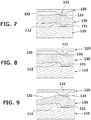
- Figures 7-9 show different examples of contact areas 132 in the motor housing 130.
- at least one contact area 132 is defined in the motor housing 130 suitable for acting on the projections 122 formed in the gearwheel 120.
- the contact area 132 is the form of a ramp whose inclination is parallel to that of the fourth ramps 112 formed in the support base 110.
- the contact area 132 is also configured as a ramp but having a different inclination than that of the fourth ramps 112 formed in the support base 110.
- the contact area 132 comprises a flat area, with no ramps defined therein.
- the second set of ramps 121 in the gearwheel 120 engages the first set of ramps 111 in the support base 110, and the third set of ramps 131 in the motor housing 130 engages the fourth set of ramps 112 in the support base 110 different from that to which second set of ramps 121 of the gearwheel 120 engage.
- the first, second, third, and fourth sets of ramps 111, 121, 131, 112 are arranged so that they can be moved relative to each other.
- the first, second, third, and fourth sets of ramps 111, 121, 131, 112 are also arranged so that they can slide independently at different times on each other, except for those sets of ramps in the same part such as the first and fourth set of ramps 111, 112 of the support base 110.
- the fourth set of ramps 112 of the support base 110 are thus arranged to act on the third set of ramps 131 of the motor housing 130 lifting it up together with the mirror housing as the electric motor M is driven.
- the second set of ramps 121 in the gearwheel 120 is arranged to act on the first set of ramps 111 of the support base 110 such that when the motor housing is driven manually, the gear wheel 120, the motor housing 130 and the electric motor M all rotate relative the support base 110.
- the support base 110 and the motor housing 130 are arranged such that, when the motor housing is rotated relative the support base 110 into a mirror unfolded or operating position where the mirror housing is arranged substantially transverse to the vehicle body, the first set of ramps 111 of the support base 110 contact the second set of ramps 121 of the gearwheel 120 but the projections 122 of the gearwheel 120 do not contact on the contact area 132 of the motor housing 130. In that angular position of the mirror housing, the gearwheel 120 does not contact the motor housing 130 but contacts the support base 110 directly. As a result, vibrations are avoided or greatly reduced.
- the fourth set of ramps 112 of the support base 110 and the third set of ramps 131 of the motor housing are configured to drive the motor housing 130 towards or away from the support base 110 as the electric motor M is operated.
- the first set of ramps 111 of the support base 110 and the second set of ramps 121 of the gearwheel 120 are configured such that the gearwheel 120 contacts the support base 110 when the motor housing 130 is rotated relative the support base 110 into a mirror unfolded or operating position where the mirror housing is arranged substantially transverse to the vehicle body. In this angular position of the mirror housing, the gearwheel 120 does not contact the motor housing 130. Since no clearance exists between the support base 110 and the gearwheel 120, the force of the wind is transmitted directly between the gearwheel 120 and the support base 110 with no vibrations.
- the third set of ramps 131 and the fourth set of ramps 112 are configured to be in contact with each other and the gearwheel 120 and the motor housing 130 are also in contact with each other through a gearwheel lower end and a motor housing lower portion.
- a compression spring 140 is arranged for pushing the motor housing 130 towards the support base 110.
- a cylindrical body 160 is integrated or otherwise attached to the support base 110. In an assembled position, the cylindrical body 160 is disposed inside the compression spring 140 with the elastic ring 150, as shown in the exploded view of figure 6 .
- the motor housing 130 In manual actuation, the motor housing 130 is rotated manually and the whole assembly is rotated to the support base 110 against the force of the spring 140 causing the second set of ramps 121 of the gearwheel 120 to get out of a space between the first set of ramps 111 in the support base 110.
- the electric motor M causes the motor housing 130 to rotate with less force than the elastic force of the spring 140 without overcoming the first and second sets of ramps 111, 121, but sufficient for causing the motor housing 130 to rotate around the gearwheel 120.
- the driving force of the electric motor M is not capable of causing the second set of ramps 121 to lift up and overcome the first sets of ramps 111 of the support base 110, overcoming the compression force of the spring 140.
- recesses 133 are formed in the contact area 132 such that in the unfolded or operating position of the rear-view mirror friction is avoided between the gearwheel 120 and the contact area 132.
Landscapes
- Engineering & Computer Science (AREA)
- Multimedia (AREA)
- Mechanical Engineering (AREA)
- Rear-View Mirror Devices That Are Mounted On The Exterior Of The Vehicle (AREA)
Abstract
Description
- The present disclosure relates to folding rear-view mirrors for motor vehicles and more specifically to actuators for driving such folding rear-view mirrors from an unfolded or operating position, where the mirror is substantially transverse to the vehicle body, into a folded or parking position, where the mirror is aligned substantially lengthwise with the vehicle body, and vice versa.
- Powered outside rear-view mirrors in motor vehicles are known in the art. They include electric drive means for driving a mirror housing with the rear-view mirror assembly in rotation to arrange the rear-view mirror from an unfolded or operating position, where the mirror is substantially transverse to the vehicle body, into a folded or parking position, where the mirror is aligned substantially lengthwise with the vehicle body, and vice versa, as required by circumstances or needs such as for example when the vehicle is running or when it is parked.
- In order to avoid or to at least reduce noise and vibrations due to friction of rotating parts with fixed rubber parts that are typically fitted in rear-view mirrors in motor vehicles for reducing noise due to air passing through, the mirror housing is configured to be lifted up to the support base as it is driven in rotation by the electric drive means. However, one main problem in known rear-view mirrors still relates to annoying vibrations and noise in operation due to manufacturing tolerances resulting from clearances between moving parts of the mirror assembly combined with the weight of current mirror assemblies. Such vibrations and noise in known folding rear-view mirror when the vehicle is moving adversely affect motor vehicle driving comfort.
- Although solutions to remove vibrations and noise have been proposed in the art such as the use of flexible seals between rear-view mirror moving parts, they have not been entirely satisfactory due to wear resulting from friction during several cycles of rotation of the housing that negatively affects effectiveness.
- For this purpose, seal based solutions have been supplemented by a mechanism capable of displacing, i.e. moving away from and/or closer to, the rear-view mirror housing relative to a base element that is mounted to the motor vehicle when the mirror housing is driven to be rotated. Thus, in use, that is when the mirror housing is unfolded for driving, the mirror housing and the base element are snugly fitted together and can be moved away from each other when the mirror is being rotated into the folded position. A series of wedges or ramps is provided having an inclination designed for properly moving away from or closer both elements together as they are rotated to each other.
-
US2014347755 , filed by the present applicant, discloses a folding rear-view mirror for motor vehicles that comprises a base member to be fixed to a vehicle, a housing for holding a rear-view mirror, a motor component to rotate the rear-view housing to the base member, and first and second sets of ramps independent of each other arranged to slide on corresponding fixed ramps of the base element and first and second resilient elements. The ramps of the first and second sets have different inclinations and the resilient elements have different spring rates from one another, depending on whether the mirror housing is manually or motor driven. -
US2018178728 also describes a folding rear-view mirror for motor vehicles that comprises a base to be fixed to a vehicle, a mirror housing, a motor housing for receiving a motor to rotate the mirror housing to the base and a connecting piece for manually rotating the motor housing to the base. A cam assembly is provided between the connecting piece and the base such that during mirror power folding, the cam assembly enables the mirror housing to lift up and rotate. - Despite these attempts for removing vibrations and noise, there still remains a need for motor vehicle folding rear-view mirrors in which noise and vibrations can be at least significantly reduced at least when the rear-view mirror is unfolded for driving.
- An actuator for an electric folding rear-view mirror for motor vehicles is disclosed herein according to claim 1 with which the prior art disadvantages can be overcome and with which a number of significant advantages is obtained. Advantageous embodiments are defined in the dependent claims.
- The present rear-view mirror actuator comprises a support base. The support base is intended to be mounted on, usually fixed to, a motor vehicle and includes first and fourth set of ramps. The present rear-view mirror actuator further includes a motor assembly that comprises a motor housing. The first set of ramps of the support base may be arranged in an inner portion thereof and the fourth set of ramps of the support base may be arranged in an outer portion thereof. The first and fourth set of ramps of the support base are arranged concentrically to each other.
- A gearwheel is attached to the support base and arranged to rotate together with the motor housing when driven manually relative to the support base between a first angular position and a second angular position. In this case, when the motor housing is driven in rotation by the electric motor, the gearwheel is attached to the support base. In this case, only the motor housing together with the electric motor move around the gearwheel.
- The gearwheel includes a second set of ramps whose inclination is adapted for manual rotation of the motor housing relative to the support base. The second set of ramps engage the first set of ramps of the support base. The gearwheel comprises an axial upper end and an axial lower end.
- The motor housing includes a third set of ramps whose inclination is equal to or less than that of the second set of ramps of the gearwheel for power rotation of the motor housing relative to the support base. The third set of ramps engage the fourth set of ramps of the support base.
- The first, second, third, and fourth sets of ramps are arranged so that they can be moved relative to each other. Some of said sets of ramps are arranged so that they can slide independently at different times on each other. This may apply for example to all the sets of ramps except for those sets of ramps in the same part such as the first and fourth set of ramps of the support base.
- The fourth set of ramps of the support base are arranged to act on the third set of ramps of the motor housing to lift up the motor housing. The motor housing and the mirror housing are attached to one another so they are thus lifted up together, as the motor housing is driven by an electric motor fitted within the motor housing. When the motor housing is rotated by the electric motor, the second set of ramps of the gearwheel is attached to the first set of ramps of the support base, while when the motor housing is rotated manually the gearwheel rotates together with the motor housing since they are attached to one another through the electric motor.
- The gearwheel is arranged to rest on the motor housing, but in certain cases directly on the support base.
- In the above described configuration, the support base and the motor housing are arranged such that, under a given angular position of the motor housing relative the support base, the first set of ramps of the support base contact the second set of ramps of the gearwheel but the gearwheel does not contact the motor housing. A used herein, the expression "a given angular position" refers to any angular position of the motor housing relative the support base, for example the first angular position, the second angular position, or any intermediate position between the first and second angular positions. In practice, said given angular position may correspond to a mirror unfolded or operating position where the mirror housing is arranged substantially transverse to the vehicle body, for driving. In that position, since the gearwheel does not contact the motor housing but contacts the support base directly the motor housing vibrations and therefore the mirror housing vibrations are advantageously avoided.
- More in detail, one of the fourth set of ramps of the support base and the third set of ramps of the motor housing is configured to drive the motor housing towards or away from the support base as the motor assembly is operated. The first set of ramps of the support base and the second set of ramps of the gearwheel are configured such that the gearwheel contacts the support base in said given angular position of the motor housing relative to the support base, with the motor assembly gearwheel not contacting the motor housing. In that case, there is no clearance between the support base and the gearwheel and thus for example the force of the wind is transmitted directly between the gearwheel and the support base with no vibrations.
- The motor housing may include at least one contact area arranged to act on downwardly extending projections of the gearwheel when the motor housing is placed out of the given angular position.
- Said contact area may be in the form of a ramp whose inclination is according to the fourth ramps such that the gearwheel does not lift up when the motor housing is rotated by the electric motor. However, the contact area ramp may have a different inclination than the fourth ramps. Still in other examples, the contact area may comprise a flat area.
- More specifically, the motor housing comprises an upper portion and a lower portion. The lower portion of the motor housing also comprises an upper end and a lower end. The axial lower end of the gearwheel comprises at least two downwardly extending projections. The upper end of the lower portion of the motor housing includes a contact area arranged to act on the downwardly extending projections of the gearwheel. The contact area may be in the form of ramps. The ramps may have an inclination according to the fourth ramps such that the gearwheel does not lift up when the motor housing is rotated by the electric motor M. The contact area may be also in the form of ramps but having different inclination than the fourth ramps. Still in other examples, the contact area may comprise flat areas. Said contact area and projections are configured such that when the motor housing is placed in said mirror unfolded or operating position the downwardly extending projections of the gearwheel rest on the contact area of the motor housing with no contact therebetween.
- The contact area also comprises corresponding recesses. The downwardly extending projections of the gearwheel axial lower end are placed above said recesses with no contact therebetween when the motor housing is placed in the given angular position.
- One non-limiting example of the present disclosure will be described in the following, with reference to the appended drawings, in which:
-
Figure 1 is a perspective view of one example of an actuator for an electric folding rear-view mirror for motor vehicles; -
Figure 2 is a sectional view of the rear-view mirror actuator offigure 1 taken from line AA infigure 4 ; -
Figure 3 is a sectional view of the rear-view mirror actuator offigure 1 taken from line BB infigure 4 ; -
Figure 4 is a top plan view of the rear-view mirror actuator offigure 1 in a first angular position; -
Figure 5 is a top plan view of the rear-view mirror actuator offigure 1 in a second angular position; -
Figure 6 is an exploded perspective view of the present rear-view mirror actuator; -
Figure 7 is a cross-sectional part view of a first example of a contact area formed in the motor housing; -
Figure 8 is a cross-sectional part view of a second example of a contact area formed in the motor housing; -
Figure 9 is a cross-sectional part view of a third example of a contact area formed in the motor housing; -
Figure 10 is an elevational view of the gearwheel; -
Figure 11 is a bottom perspective view of the gearwheel; and -
Figure 12 is a top perspective view of the gearwheel. - One example of an actuator for a folding rear-view mirror for motor vehicles is shown in
figures 1-12 . In said figures, the actuator has been generally indicated byreference numeral 100. It comprises asupport base 110 adapted to be mounted fixed on the outside of a motor vehicle body, in a position suitable for vision when driving. Theactuator 100 is for being attached to a mirror housing, not shown in the drawings, and it is also rotatably mounted to thesupport base 110. - In this example, the mirror housing and the
motor housing 130 are separate parts attached together. However, the mirror housing and themotor housing 130 could be made integral with each other. Themotor housing 130 is adapted to receive an electric motor M therein. The electric motor M is intended to rotate themotor housing 130, and thus the mirror housing, relative to thesupport base 110 between a mirror unfolded or operating position and a mirror folded or non-operating position, or vice versa. - In particular, the electric motor M is arranged to drive the
motor housing 130 relative to agearwheel 120. To this effect, a second set oframps 121 of thegearwheel 120 engages the first set oframps 111 of thesupport base 110. Rotation of the electric motor M causes rotation of themotor housing 130 relative to thesupport base 110. - The
support base 110 includes a first set oframps 111 configured for manual operation of themotor housing 130 to rotate relative to thesupport base 110. Thesupport base 110 also includes a fourth set oframps 112 configured for power operation of themotor housing 130 to rotate relative to thesupport base 110. The first and fourth set oframps support base 110. The first set oframps 111 is arranged in an inner portion of thesupport base 110. The fourth set oframps 112 of thesupport base 110 is arranged in an outer portion of thesupport base 110. - A
gearwheel 120 is releasably attached to thesupport base 110. Thegearwheel 120 is arranged to rotate together with themotor housing 130 relative to thesupport base 110 when driven manually, between an unfolded or operating position, where the mirror housing is substantially transverse to the vehicle body, into a folded or parking position, where the mirror housing is aligned substantially lengthwise with the vehicle body, and vice versa. When themotor housing 130 is rotated by the electric motor M, thegearwheel 120 is attached to thesupport base 110, since the driving force of the electric motor M on thegearwheel 120 is less than the force of thespring 140 against themotor housing 130 and thesupport base 110 and is not able to disengage the second set oframps 121 of thegearwheel 120 from the first set oframps 111 of thesupport base 110. - As shown in
figures 10-12 , thegearwheel 120 includes a second set oframps 121 for manual rotation of themotor housing 130. Themotor housing 130 includes a third set oframps 131 for power rotation. The inclination of the second set oframps 121 is adapted for manual rotation of themotor housing 130 relative to thesupport base 110. The inclination of the third set oframps 131 is equal to or less than the inclination of the second set oframps 121 of thegearwheel 120 for rotation of the motor housing relative to thesupport base 110 by the electric motor M since, torque required for manual movement of themotor housing 130 is larger than for movement by the electric motor M. - The
gearwheel 120 comprises at least two downwardly extendingprojections 122 arranged at a lower end thereof as shown infigures 10-12 . Themotor housing 130 includes acontact area 132 arranged to act on theprojections 122 of thegearwheel 120 when the motor housing (130) is placed out of the unfolded or operating position. Thecontact area 132 may be in the form of ramps having an inclination according to the fourth ramps such that thegearwheel 120 does not lift up when themotor housing 130 is rotated by the electric motor M. Thecontact area 132 may be also in the form of ramps but having different inclination than the fourth ramps. Still in other examples, thecontact area 132 may comprise flat areas. Saidcontact area 132 andprojections 122 are configured such that when themotor housing 130 is placed in said mirror unfolded or operating position the downwardly extendingprojections 122 of thegearwheel 120 rest on thecontact area 132 of themotor housing 130 with no contact therebetween. -
Figures 7-9 show different examples ofcontact areas 132 in themotor housing 130. In said examples, at least onecontact area 132 is defined in themotor housing 130 suitable for acting on theprojections 122 formed in thegearwheel 120. In the example shown infigure 7 , thecontact area 132 is the form of a ramp whose inclination is parallel to that of thefourth ramps 112 formed in thesupport base 110. In the example shown infigure 8 , thecontact area 132 is also configured as a ramp but having a different inclination than that of thefourth ramps 112 formed in thesupport base 110. In the example shown infigure 9 , thecontact area 132 comprises a flat area, with no ramps defined therein. - The second set of
ramps 121 in thegearwheel 120 engages the first set oframps 111 in thesupport base 110, and the third set oframps 131 in themotor housing 130 engages the fourth set oframps 112 in thesupport base 110 different from that to which second set oframps 121 of thegearwheel 120 engage. - The first, second, third, and fourth sets of
ramps ramps ramps support base 110. - The fourth set of
ramps 112 of thesupport base 110 are thus arranged to act on the third set oframps 131 of themotor housing 130 lifting it up together with the mirror housing as the electric motor M is driven. The second set oframps 121 in thegearwheel 120 is arranged to act on the first set oframps 111 of thesupport base 110 such that when the motor housing is driven manually, thegear wheel 120, themotor housing 130 and the electric motor M all rotate relative thesupport base 110. - The
support base 110 and themotor housing 130 are arranged such that, when the motor housing is rotated relative thesupport base 110 into a mirror unfolded or operating position where the mirror housing is arranged substantially transverse to the vehicle body, the first set oframps 111 of thesupport base 110 contact the second set oframps 121 of thegearwheel 120 but theprojections 122 of thegearwheel 120 do not contact on thecontact area 132 of themotor housing 130. In that angular position of the mirror housing, thegearwheel 120 does not contact themotor housing 130 but contacts thesupport base 110 directly. As a result, vibrations are avoided or greatly reduced. - The fourth set of
ramps 112 of thesupport base 110 and the third set oframps 131 of the motor housing are configured to drive themotor housing 130 towards or away from thesupport base 110 as the electric motor M is operated. The first set oframps 111 of thesupport base 110 and the second set oframps 121 of thegearwheel 120 are configured such that thegearwheel 120 contacts thesupport base 110 when themotor housing 130 is rotated relative thesupport base 110 into a mirror unfolded or operating position where the mirror housing is arranged substantially transverse to the vehicle body. In this angular position of the mirror housing, thegearwheel 120 does not contact themotor housing 130. Since no clearance exists between thesupport base 110 and thegearwheel 120, the force of the wind is transmitted directly between thegearwheel 120 and thesupport base 110 with no vibrations. - When the
motor housing 130 is out of the mirror unfolded or operating position, the third set oframps 131 and the fourth set oframps 112 are configured to be in contact with each other and thegearwheel 120 and themotor housing 130 are also in contact with each other through a gearwheel lower end and a motor housing lower portion. - A
compression spring 140 is arranged for pushing themotor housing 130 towards thesupport base 110. Acylindrical body 160 is integrated or otherwise attached to thesupport base 110. In an assembled position, thecylindrical body 160 is disposed inside thecompression spring 140 with theelastic ring 150, as shown in the exploded view offigure 6 . - In manual actuation, the
motor housing 130 is rotated manually and the whole assembly is rotated to thesupport base 110 against the force of thespring 140 causing the second set oframps 121 of thegearwheel 120 to get out of a space between the first set oframps 111 in thesupport base 110. - In power actuation, the electric motor M causes the
motor housing 130 to rotate with less force than the elastic force of thespring 140 without overcoming the first and second sets oframps motor housing 130 to rotate around thegearwheel 120. Thus, the driving force of the electric motor M is not capable of causing the second set oframps 121 to lift up and overcome the first sets oframps 111 of thesupport base 110, overcoming the compression force of thespring 140. - As shown in
figure 7 , recesses 133 are formed in thecontact area 132 such that in the unfolded or operating position of the rear-view mirror friction is avoided between thegearwheel 120 and thecontact area 132. - Although only a number of examples have been disclosed herein, other alternatives, modifications, uses and/or equivalents thereof are possible. Furthermore, all possible combinations of the described examples are also covered. Thus, the scope of the present disclosure should not be limited by particular examples, but should be determined only by a fair reading of the claims that follow. Reference signs related to drawings placed in parentheses in a claim are solely for attempting to increase the intelligibility of the claim, and shall not be construed as limiting the scope of the claim.
Claims (12)
- Actuator (100) for an electric folding rear-view mirror for motor vehicles, the actuator (100) comprising:- a support base (110) to be mounted on a vehicle;- first and fourth set of ramps (111, 112) formed in the support base (110);- a motor assembly (M) comprising a motor housing (130), and a gearwheel (120) arranged to rotate the motor housing (130) relative to the support base (110) between a first angular position and a second angular position;- a second set of ramps (121) formed in the gearwheel (120) whose inclination is adapted for manual rotation of the gearwheel (120) relative to the support base (110), said second set of ramps (121) engaging one set of said first and fourth set of ramps (111, 112); and- a third set of ramps (131) formed in the motor housing (130) whose inclination is equal to or less than that of the second set of ramps (121) for power rotation of the motor housing (130) relative to the support base (110), said third set of ramps (131) engaging one set of said first and fourth set of ramps (111, 112) different from that to which second set of ramps (121) engage,whereby at least some of the sets of ramps are arranged so that they can be moved relative to each other, and can slide independently at different times on each other;
characterized in that the support base (110) and the motor housing (130) are configured such that, under a given angular position of the motor housing (130) relative to the support base (110), the first set of ramps (111) of the support base (110) contact the second set of ramps (121) of the gearwheel (120) but the gearwheel (120) does not contact the motor housing (130). - The actuator (100) of claim 1, wherein, one of the fourth set of ramps (112) of the support base (110) and the third set of ramps (131) of the motor housing (130) is configured to drive the motor housing (130) away from the support base (110) as the motor assembly (M) is operated; and the first set of ramps (111) and the second sets of ramps (121) are configured such that the motor assembly gearwheel (120) contacts the support base (110) in the given angular position of the motor housing (130) relative to the support base (110), with the motor assembly gearwheel (120) not contacting the motor housing (130).
- The actuator (100) of claim 1 or 2, wherein said given angular position of the motor housing (130) is one of the first angular position, the second angular position or an intermediate position between the first and second angular positions.
- The actuator (100) of claim 1 to 3, wherein the gearwheel (120) comprises an axial upper end and an axial lower end, and the motor housing (130) comprises an upper portion and a lower portion, and the lower portion of the motor housing (130) also comprises an upper end and a lower end, and wherein when the motor housing (130) is out of the given angular position relative to the support base (110), the third set of ramps (131) and the fourth set of ramps (112) are configured to be in contact and the gearwheel (120) and the motor housing (130) are also in contact through the gearwheel axial lower end and the upper end of the lower portion of the motor housing (130).
- The actuator (100) of claims 4, wherein the axial lower end of the gearwheel (120) comprises at least two downwardly extending projections (122) and the upper end of the lower portion of the motor housing (130) comprises corresponding recesses (133).
- The actuator (100) of claim 5, wherein the downwardly extending projections (122) of the gearwheel axial lower end are placed above the recesses (133) of the lower portion of the motor housing (130) with no contact therebetween when the motor housing (130) is placed in the given angular position.
- The actuator (100) of claim 5, wherein the upper end of the lower portion of the motor housing (130) includes at least one contact area (132) arranged to act on downwardly extending projections (122) of the gearwheel (120) when the motor housing (130) is placed out of the given angular position.
- The actuator (100) of claim 7, wherein the contact area (132) is in the form of a ramp.
- The actuator (100) of claim 8, wherein the contact area ramp (132) has an inclination according to the fourth ramps (112) such that the gearwheel (120) does not lift up when the motor housing (130) is rotated by the electric motor (M).
- The actuator (100) of claim 8, wherein the contact area ramp (132) has a different inclination than the fourth ramps (112).
- The actuator (100) of claim 7, wherein the contact area (132) comprises a flat area.
- The actuator (100) of any of the claims 1-11, wherein the first set of ramps (111) is arranged in an inner portion of the support base (110) and the fourth set of ramps (112) is arranged in an outer portion of the support base (110), and the first and fourth set of ramps (111, 112) are arranged concentrically to each other.
Priority Applications (1)
| Application Number | Priority Date | Filing Date | Title |
|---|---|---|---|
| EP18382810.2A EP3653442B1 (en) | 2018-11-15 | 2018-11-15 | Actuator for an electric folding rear-view mirror for motor vehicles |
Applications Claiming Priority (1)
| Application Number | Priority Date | Filing Date | Title |
|---|---|---|---|
| EP18382810.2A EP3653442B1 (en) | 2018-11-15 | 2018-11-15 | Actuator for an electric folding rear-view mirror for motor vehicles |
Publications (2)
| Publication Number | Publication Date |
|---|---|
| EP3653442A1 true EP3653442A1 (en) | 2020-05-20 |
| EP3653442B1 EP3653442B1 (en) | 2022-09-21 |
Family
ID=64572277
Family Applications (1)
| Application Number | Title | Priority Date | Filing Date |
|---|---|---|---|
| EP18382810.2A Active EP3653442B1 (en) | 2018-11-15 | 2018-11-15 | Actuator for an electric folding rear-view mirror for motor vehicles |
Country Status (1)
| Country | Link |
|---|---|
| EP (1) | EP3653442B1 (en) |
Cited By (1)
| Publication number | Priority date | Publication date | Assignee | Title |
|---|---|---|---|---|
| US20230415650A1 (en) * | 2020-11-09 | 2023-12-28 | Ningbo Jingcheng Car Industry Co., Ltd. | Electric folding device for exterior rear-view mirror of vehicle |
Citations (4)
| Publication number | Priority date | Publication date | Assignee | Title |
|---|---|---|---|---|
| WO2012047104A1 (en) | 2010-10-06 | 2012-04-12 | Mci (Mirror Controls International) Netherlands B.V. | Adjustment mechanism |
| EP2639110A1 (en) | 2012-03-14 | 2013-09-18 | Magna Auteca AG | Drive assembly for an external rear mirror in a vehicle |
| US20140347755A1 (en) | 2013-05-23 | 2014-11-27 | Fico Mirrors, S.A. | Folding Rearview Mirror For Motor Vehicles |
| US20180178728A1 (en) | 2015-08-22 | 2018-06-28 | Ningbo Jingcheng Car Industry Co., Ltd. | Electric Folding Device for Outer Rearview Mirror of a Vehicle |
-
2018
- 2018-11-15 EP EP18382810.2A patent/EP3653442B1/en active Active
Patent Citations (4)
| Publication number | Priority date | Publication date | Assignee | Title |
|---|---|---|---|---|
| WO2012047104A1 (en) | 2010-10-06 | 2012-04-12 | Mci (Mirror Controls International) Netherlands B.V. | Adjustment mechanism |
| EP2639110A1 (en) | 2012-03-14 | 2013-09-18 | Magna Auteca AG | Drive assembly for an external rear mirror in a vehicle |
| US20140347755A1 (en) | 2013-05-23 | 2014-11-27 | Fico Mirrors, S.A. | Folding Rearview Mirror For Motor Vehicles |
| US20180178728A1 (en) | 2015-08-22 | 2018-06-28 | Ningbo Jingcheng Car Industry Co., Ltd. | Electric Folding Device for Outer Rearview Mirror of a Vehicle |
Cited By (1)
| Publication number | Priority date | Publication date | Assignee | Title |
|---|---|---|---|---|
| US20230415650A1 (en) * | 2020-11-09 | 2023-12-28 | Ningbo Jingcheng Car Industry Co., Ltd. | Electric folding device for exterior rear-view mirror of vehicle |
Also Published As
| Publication number | Publication date |
|---|---|
| EP3653442B1 (en) | 2022-09-21 |
Similar Documents
| Publication | Publication Date | Title |
|---|---|---|
| EP2805853B1 (en) | Folding rearview mirror for motor vehicles | |
| EP2159102B1 (en) | Vehicle mirror power fold mechanism | |
| JP4845911B2 (en) | Hinge mechanism and vehicle seat having the mechanism | |
| JP4754549B2 (en) | Functional device with pivotable element | |
| CN104512240A (en) | Actuator and Grille Incorporating the Actuator | |
| US11396264B2 (en) | Powerfold actuator for exterior mirror | |
| CN111032434A (en) | Motorized fold actuator for external mirror | |
| EP3653442B1 (en) | Actuator for an electric folding rear-view mirror for motor vehicles | |
| WO2009035931A1 (en) | Universal folding bracket assembly for either manual fold or power fold rearview mirrors | |
| CN107837150B (en) | in-wheel motor driving state adjusting device | |
| CN103144609A (en) | Drive unit | |
| JP3962918B2 (en) | Hinge actuator for vehicle wing mirror | |
| US20230415650A1 (en) | Electric folding device for exterior rear-view mirror of vehicle | |
| CN105599685B (en) | Rearview mirror assembly for motor vehicle | |
| US20150217695A1 (en) | Rear view mirror assembly for motor vehicles | |
| CN214492722U (en) | Folding driving device | |
| CN112810537A (en) | Folding driving device | |
| CN220180670U (en) | Passenger train rear-view mirror adjusting device | |
| US10703280B2 (en) | Actuator mechanism for a fold rear-view mirror assembly | |
| CN111361637B (en) | Steering and aligning auxiliary device, steering mechanism and vehicle | |
| EP1597108B1 (en) | Power retraction system for a fold in floor seat assembly | |
| KR200172296Y1 (en) | Wiper depressed parking device for a car | |
| KR19980058615U (en) | Car reverse | |
| KR20070052383A (en) | Sliding type side mirror | |
| KR20060084642A (en) | Rear wiping device of vehicle |
Legal Events
| Date | Code | Title | Description |
|---|---|---|---|
| PUAI | Public reference made under article 153(3) epc to a published international application that has entered the european phase |
Free format text: ORIGINAL CODE: 0009012 |
|
| STAA | Information on the status of an ep patent application or granted ep patent |
Free format text: STATUS: THE APPLICATION HAS BEEN PUBLISHED |
|
| AK | Designated contracting states |
Kind code of ref document: A1 Designated state(s): AL AT BE BG CH CY CZ DE DK EE ES FI FR GB GR HR HU IE IS IT LI LT LU LV MC MK MT NL NO PL PT RO RS SE SI SK SM TR |
|
| AX | Request for extension of the european patent |
Extension state: BA ME |
|
| STAA | Information on the status of an ep patent application or granted ep patent |
Free format text: STATUS: REQUEST FOR EXAMINATION WAS MADE |
|
| TPAC | Observations filed by third parties |
Free format text: ORIGINAL CODE: EPIDOSNTIPA |
|
| 17P | Request for examination filed |
Effective date: 20201120 |
|
| RBV | Designated contracting states (corrected) |
Designated state(s): AL AT BE BG CH CY CZ DE DK EE ES FI FR GB GR HR HU IE IS IT LI LT LU LV MC MK MT NL NO PL PT RO RS SE SI SK SM TR |
|
| STAA | Information on the status of an ep patent application or granted ep patent |
Free format text: STATUS: EXAMINATION IS IN PROGRESS |
|
| 17Q | First examination report despatched |
Effective date: 20210212 |
|
| STAA | Information on the status of an ep patent application or granted ep patent |
Free format text: STATUS: EXAMINATION IS IN PROGRESS |
|
| TPAC | Observations filed by third parties |
Free format text: ORIGINAL CODE: EPIDOSNTIPA |
|
| GRAP | Despatch of communication of intention to grant a patent |
Free format text: ORIGINAL CODE: EPIDOSNIGR1 |
|
| STAA | Information on the status of an ep patent application or granted ep patent |
Free format text: STATUS: GRANT OF PATENT IS INTENDED |
|
| INTG | Intention to grant announced |
Effective date: 20220414 |
|
| GRAS | Grant fee paid |
Free format text: ORIGINAL CODE: EPIDOSNIGR3 |
|
| GRAA | (expected) grant |
Free format text: ORIGINAL CODE: 0009210 |
|
| STAA | Information on the status of an ep patent application or granted ep patent |
Free format text: STATUS: THE PATENT HAS BEEN GRANTED |
|
| AK | Designated contracting states |
Kind code of ref document: B1 Designated state(s): AL AT BE BG CH CY CZ DE DK EE ES FI FR GB GR HR HU IE IS IT LI LT LU LV MC MK MT NL NO PL PT RO RS SE SI SK SM TR |
|
| REG | Reference to a national code |
Ref country code: GB Ref legal event code: FG4D |
|
| REG | Reference to a national code |
Ref country code: CH Ref legal event code: EP |
|
| REG | Reference to a national code |
Ref country code: IE Ref legal event code: FG4D |
|
| REG | Reference to a national code |
Ref country code: DE Ref legal event code: R096 Ref document number: 602018040858 Country of ref document: DE |
|
| REG | Reference to a national code |
Ref country code: AT Ref legal event code: REF Ref document number: 1519803 Country of ref document: AT Kind code of ref document: T Effective date: 20221015 |
|
| REG | Reference to a national code |
Ref country code: LT Ref legal event code: MG9D |
|
| REG | Reference to a national code |
Ref country code: NL Ref legal event code: MP Effective date: 20220921 |
|
| PG25 | Lapsed in a contracting state [announced via postgrant information from national office to epo] |
Ref country code: SE Free format text: LAPSE BECAUSE OF FAILURE TO SUBMIT A TRANSLATION OF THE DESCRIPTION OR TO PAY THE FEE WITHIN THE PRESCRIBED TIME-LIMIT Effective date: 20220921 Ref country code: RS Free format text: LAPSE BECAUSE OF FAILURE TO SUBMIT A TRANSLATION OF THE DESCRIPTION OR TO PAY THE FEE WITHIN THE PRESCRIBED TIME-LIMIT Effective date: 20220921 Ref country code: NO Free format text: LAPSE BECAUSE OF FAILURE TO SUBMIT A TRANSLATION OF THE DESCRIPTION OR TO PAY THE FEE WITHIN THE PRESCRIBED TIME-LIMIT Effective date: 20221221 Ref country code: LV Free format text: LAPSE BECAUSE OF FAILURE TO SUBMIT A TRANSLATION OF THE DESCRIPTION OR TO PAY THE FEE WITHIN THE PRESCRIBED TIME-LIMIT Effective date: 20220921 Ref country code: LT Free format text: LAPSE BECAUSE OF FAILURE TO SUBMIT A TRANSLATION OF THE DESCRIPTION OR TO PAY THE FEE WITHIN THE PRESCRIBED TIME-LIMIT Effective date: 20220921 Ref country code: FI Free format text: LAPSE BECAUSE OF FAILURE TO SUBMIT A TRANSLATION OF THE DESCRIPTION OR TO PAY THE FEE WITHIN THE PRESCRIBED TIME-LIMIT Effective date: 20220921 |
|
| REG | Reference to a national code |
Ref country code: AT Ref legal event code: MK05 Ref document number: 1519803 Country of ref document: AT Kind code of ref document: T Effective date: 20220921 |
|
| PG25 | Lapsed in a contracting state [announced via postgrant information from national office to epo] |
Ref country code: HR Free format text: LAPSE BECAUSE OF FAILURE TO SUBMIT A TRANSLATION OF THE DESCRIPTION OR TO PAY THE FEE WITHIN THE PRESCRIBED TIME-LIMIT Effective date: 20220921 Ref country code: GR Free format text: LAPSE BECAUSE OF FAILURE TO SUBMIT A TRANSLATION OF THE DESCRIPTION OR TO PAY THE FEE WITHIN THE PRESCRIBED TIME-LIMIT Effective date: 20221222 |
|
| PG25 | Lapsed in a contracting state [announced via postgrant information from national office to epo] |
Ref country code: SM Free format text: LAPSE BECAUSE OF FAILURE TO SUBMIT A TRANSLATION OF THE DESCRIPTION OR TO PAY THE FEE WITHIN THE PRESCRIBED TIME-LIMIT Effective date: 20220921 Ref country code: RO Free format text: LAPSE BECAUSE OF FAILURE TO SUBMIT A TRANSLATION OF THE DESCRIPTION OR TO PAY THE FEE WITHIN THE PRESCRIBED TIME-LIMIT Effective date: 20220921 Ref country code: PT Free format text: LAPSE BECAUSE OF FAILURE TO SUBMIT A TRANSLATION OF THE DESCRIPTION OR TO PAY THE FEE WITHIN THE PRESCRIBED TIME-LIMIT Effective date: 20230123 Ref country code: ES Free format text: LAPSE BECAUSE OF FAILURE TO SUBMIT A TRANSLATION OF THE DESCRIPTION OR TO PAY THE FEE WITHIN THE PRESCRIBED TIME-LIMIT Effective date: 20220921 Ref country code: CZ Free format text: LAPSE BECAUSE OF FAILURE TO SUBMIT A TRANSLATION OF THE DESCRIPTION OR TO PAY THE FEE WITHIN THE PRESCRIBED TIME-LIMIT Effective date: 20220921 Ref country code: AT Free format text: LAPSE BECAUSE OF FAILURE TO SUBMIT A TRANSLATION OF THE DESCRIPTION OR TO PAY THE FEE WITHIN THE PRESCRIBED TIME-LIMIT Effective date: 20220921 |
|
| PG25 | Lapsed in a contracting state [announced via postgrant information from national office to epo] |
Ref country code: SK Free format text: LAPSE BECAUSE OF FAILURE TO SUBMIT A TRANSLATION OF THE DESCRIPTION OR TO PAY THE FEE WITHIN THE PRESCRIBED TIME-LIMIT Effective date: 20220921 Ref country code: PL Free format text: LAPSE BECAUSE OF FAILURE TO SUBMIT A TRANSLATION OF THE DESCRIPTION OR TO PAY THE FEE WITHIN THE PRESCRIBED TIME-LIMIT Effective date: 20220921 Ref country code: IS Free format text: LAPSE BECAUSE OF FAILURE TO SUBMIT A TRANSLATION OF THE DESCRIPTION OR TO PAY THE FEE WITHIN THE PRESCRIBED TIME-LIMIT Effective date: 20230121 Ref country code: EE Free format text: LAPSE BECAUSE OF FAILURE TO SUBMIT A TRANSLATION OF THE DESCRIPTION OR TO PAY THE FEE WITHIN THE PRESCRIBED TIME-LIMIT Effective date: 20220921 |
|
| REG | Reference to a national code |
Ref country code: DE Ref legal event code: R097 Ref document number: 602018040858 Country of ref document: DE |
|
| PG25 | Lapsed in a contracting state [announced via postgrant information from national office to epo] |
Ref country code: NL Free format text: LAPSE BECAUSE OF FAILURE TO SUBMIT A TRANSLATION OF THE DESCRIPTION OR TO PAY THE FEE WITHIN THE PRESCRIBED TIME-LIMIT Effective date: 20220921 Ref country code: MC Free format text: LAPSE BECAUSE OF FAILURE TO SUBMIT A TRANSLATION OF THE DESCRIPTION OR TO PAY THE FEE WITHIN THE PRESCRIBED TIME-LIMIT Effective date: 20220921 Ref country code: AL Free format text: LAPSE BECAUSE OF FAILURE TO SUBMIT A TRANSLATION OF THE DESCRIPTION OR TO PAY THE FEE WITHIN THE PRESCRIBED TIME-LIMIT Effective date: 20220921 |
|
| REG | Reference to a national code |
Ref country code: CH Ref legal event code: PL |
|
| REG | Reference to a national code |
Ref country code: BE Ref legal event code: MM Effective date: 20221130 |
|
| PLBE | No opposition filed within time limit |
Free format text: ORIGINAL CODE: 0009261 |
|
| STAA | Information on the status of an ep patent application or granted ep patent |
Free format text: STATUS: NO OPPOSITION FILED WITHIN TIME LIMIT |
|
| PG25 | Lapsed in a contracting state [announced via postgrant information from national office to epo] |
Ref country code: LI Free format text: LAPSE BECAUSE OF NON-PAYMENT OF DUE FEES Effective date: 20221130 Ref country code: DK Free format text: LAPSE BECAUSE OF FAILURE TO SUBMIT A TRANSLATION OF THE DESCRIPTION OR TO PAY THE FEE WITHIN THE PRESCRIBED TIME-LIMIT Effective date: 20220921 Ref country code: CH Free format text: LAPSE BECAUSE OF NON-PAYMENT OF DUE FEES Effective date: 20221130 |
|
| GBPC | Gb: european patent ceased through non-payment of renewal fee |
Effective date: 20221221 |
|
| 26N | No opposition filed |
Effective date: 20230622 |
|
| PG25 | Lapsed in a contracting state [announced via postgrant information from national office to epo] |
Ref country code: SI Free format text: LAPSE BECAUSE OF FAILURE TO SUBMIT A TRANSLATION OF THE DESCRIPTION OR TO PAY THE FEE WITHIN THE PRESCRIBED TIME-LIMIT Effective date: 20220921 Ref country code: LU Free format text: LAPSE BECAUSE OF NON-PAYMENT OF DUE FEES Effective date: 20221115 |
|
| PG25 | Lapsed in a contracting state [announced via postgrant information from national office to epo] |
Ref country code: IE Free format text: LAPSE BECAUSE OF NON-PAYMENT OF DUE FEES Effective date: 20221115 Ref country code: GB Free format text: LAPSE BECAUSE OF NON-PAYMENT OF DUE FEES Effective date: 20221221 |
|
| PG25 | Lapsed in a contracting state [announced via postgrant information from national office to epo] |
Ref country code: FR Free format text: LAPSE BECAUSE OF NON-PAYMENT OF DUE FEES Effective date: 20221121 Ref country code: BE Free format text: LAPSE BECAUSE OF NON-PAYMENT OF DUE FEES Effective date: 20221130 |
|
| PGFP | Annual fee paid to national office [announced via postgrant information from national office to epo] |
Ref country code: DE Payment date: 20231129 Year of fee payment: 6 |
|
| PG25 | Lapsed in a contracting state [announced via postgrant information from national office to epo] |
Ref country code: HU Free format text: LAPSE BECAUSE OF FAILURE TO SUBMIT A TRANSLATION OF THE DESCRIPTION OR TO PAY THE FEE WITHIN THE PRESCRIBED TIME-LIMIT; INVALID AB INITIO Effective date: 20181115 |
|
| PG25 | Lapsed in a contracting state [announced via postgrant information from national office to epo] |
Ref country code: CY Free format text: LAPSE BECAUSE OF FAILURE TO SUBMIT A TRANSLATION OF THE DESCRIPTION OR TO PAY THE FEE WITHIN THE PRESCRIBED TIME-LIMIT Effective date: 20220921 |
|
| PG25 | Lapsed in a contracting state [announced via postgrant information from national office to epo] |
Ref country code: MK Free format text: LAPSE BECAUSE OF FAILURE TO SUBMIT A TRANSLATION OF THE DESCRIPTION OR TO PAY THE FEE WITHIN THE PRESCRIBED TIME-LIMIT Effective date: 20220921 Ref country code: IT Free format text: LAPSE BECAUSE OF FAILURE TO SUBMIT A TRANSLATION OF THE DESCRIPTION OR TO PAY THE FEE WITHIN THE PRESCRIBED TIME-LIMIT Effective date: 20220921 |
|
| PG25 | Lapsed in a contracting state [announced via postgrant information from national office to epo] |
Ref country code: TR Free format text: LAPSE BECAUSE OF FAILURE TO SUBMIT A TRANSLATION OF THE DESCRIPTION OR TO PAY THE FEE WITHIN THE PRESCRIBED TIME-LIMIT Effective date: 20220921 |
|
| PG25 | Lapsed in a contracting state [announced via postgrant information from national office to epo] |
Ref country code: BG Free format text: LAPSE BECAUSE OF FAILURE TO SUBMIT A TRANSLATION OF THE DESCRIPTION OR TO PAY THE FEE WITHIN THE PRESCRIBED TIME-LIMIT Effective date: 20220921 |