EP3653256B1 - Control system for movement reconstruction and/or restoration for a patient - Google Patents
Control system for movement reconstruction and/or restoration for a patient Download PDFInfo
- Publication number
- EP3653256B1 EP3653256B1 EP18205821.4A EP18205821A EP3653256B1 EP 3653256 B1 EP3653256 B1 EP 3653256B1 EP 18205821 A EP18205821 A EP 18205821A EP 3653256 B1 EP3653256 B1 EP 3653256B1
- Authority
- EP
- European Patent Office
- Prior art keywords
- patient
- stimulation
- control system
- sensor
- movement
- Prior art date
- Legal status (The legal status is an assumption and is not a legal conclusion. Google has not performed a legal analysis and makes no representation as to the accuracy of the status listed.)
- Active
Links
Images




Classifications
-
- A—HUMAN NECESSITIES
- A61—MEDICAL OR VETERINARY SCIENCE; HYGIENE
- A61N—ELECTROTHERAPY; MAGNETOTHERAPY; RADIATION THERAPY; ULTRASOUND THERAPY
- A61N1/00—Electrotherapy; Circuits therefor
- A61N1/18—Applying electric currents by contact electrodes
- A61N1/32—Applying electric currents by contact electrodes alternating or intermittent currents
- A61N1/36—Applying electric currents by contact electrodes alternating or intermittent currents for stimulation
- A61N1/36014—External stimulators, e.g. with patch electrodes
- A61N1/3603—Control systems
- A61N1/36031—Control systems using physiological parameters for adjustment
-
- A—HUMAN NECESSITIES
- A61—MEDICAL OR VETERINARY SCIENCE; HYGIENE
- A61N—ELECTROTHERAPY; MAGNETOTHERAPY; RADIATION THERAPY; ULTRASOUND THERAPY
- A61N1/00—Electrotherapy; Circuits therefor
- A61N1/02—Details
- A61N1/04—Electrodes
- A61N1/0404—Electrodes for external use
- A61N1/0472—Structure-related aspects
- A61N1/0476—Array electrodes (including any electrode arrangement with more than one electrode for at least one of the polarities)
-
- A—HUMAN NECESSITIES
- A61—MEDICAL OR VETERINARY SCIENCE; HYGIENE
- A61B—DIAGNOSIS; SURGERY; IDENTIFICATION
- A61B5/00—Measuring for diagnostic purposes; Identification of persons
- A61B5/0002—Remote monitoring of patients using telemetry, e.g. transmission of vital signals via a communication network
- A61B5/0015—Remote monitoring of patients using telemetry, e.g. transmission of vital signals via a communication network characterised by features of the telemetry system
- A61B5/002—Monitoring the patient using a local or closed circuit, e.g. in a room or building
-
- A—HUMAN NECESSITIES
- A61—MEDICAL OR VETERINARY SCIENCE; HYGIENE
- A61B—DIAGNOSIS; SURGERY; IDENTIFICATION
- A61B5/00—Measuring for diagnostic purposes; Identification of persons
- A61B5/0002—Remote monitoring of patients using telemetry, e.g. transmission of vital signals via a communication network
- A61B5/0015—Remote monitoring of patients using telemetry, e.g. transmission of vital signals via a communication network characterised by features of the telemetry system
- A61B5/0024—Remote monitoring of patients using telemetry, e.g. transmission of vital signals via a communication network characterised by features of the telemetry system for multiple sensor units attached to the patient, e.g. using a body or personal area network
-
- A—HUMAN NECESSITIES
- A61—MEDICAL OR VETERINARY SCIENCE; HYGIENE
- A61B—DIAGNOSIS; SURGERY; IDENTIFICATION
- A61B5/00—Measuring for diagnostic purposes; Identification of persons
- A61B5/103—Measuring devices for testing the shape, pattern, colour, size or movement of the body or parts thereof, for diagnostic purposes
- A61B5/1036—Measuring load distribution, e.g. podologic studies
-
- A—HUMAN NECESSITIES
- A61—MEDICAL OR VETERINARY SCIENCE; HYGIENE
- A61B—DIAGNOSIS; SURGERY; IDENTIFICATION
- A61B5/00—Measuring for diagnostic purposes; Identification of persons
- A61B5/103—Measuring devices for testing the shape, pattern, colour, size or movement of the body or parts thereof, for diagnostic purposes
- A61B5/11—Measuring movement of the entire body or parts thereof, e.g. head or hand tremor or mobility of a limb
- A61B5/112—Gait analysis
-
- A—HUMAN NECESSITIES
- A61—MEDICAL OR VETERINARY SCIENCE; HYGIENE
- A61B—DIAGNOSIS; SURGERY; IDENTIFICATION
- A61B5/00—Measuring for diagnostic purposes; Identification of persons
- A61B5/68—Arrangements of detecting, measuring or recording means, e.g. sensors, in relation to patient
- A61B5/6801—Arrangements of detecting, measuring or recording means, e.g. sensors, in relation to patient specially adapted to be attached to or worn on the body surface
- A61B5/6802—Sensor mounted on worn items
- A61B5/6804—Garments; Clothes
- A61B5/6807—Footwear
-
- A—HUMAN NECESSITIES
- A61—MEDICAL OR VETERINARY SCIENCE; HYGIENE
- A61B—DIAGNOSIS; SURGERY; IDENTIFICATION
- A61B5/00—Measuring for diagnostic purposes; Identification of persons
- A61B5/68—Arrangements of detecting, measuring or recording means, e.g. sensors, in relation to patient
- A61B5/6801—Arrangements of detecting, measuring or recording means, e.g. sensors, in relation to patient specially adapted to be attached to or worn on the body surface
- A61B5/6813—Specially adapted to be attached to a specific body part
- A61B5/6823—Trunk, e.g., chest, back, abdomen, hip
-
- A—HUMAN NECESSITIES
- A61—MEDICAL OR VETERINARY SCIENCE; HYGIENE
- A61B—DIAGNOSIS; SURGERY; IDENTIFICATION
- A61B5/00—Measuring for diagnostic purposes; Identification of persons
- A61B5/68—Arrangements of detecting, measuring or recording means, e.g. sensors, in relation to patient
- A61B5/6801—Arrangements of detecting, measuring or recording means, e.g. sensors, in relation to patient specially adapted to be attached to or worn on the body surface
- A61B5/6813—Specially adapted to be attached to a specific body part
- A61B5/6828—Leg
-
- A—HUMAN NECESSITIES
- A61—MEDICAL OR VETERINARY SCIENCE; HYGIENE
- A61B—DIAGNOSIS; SURGERY; IDENTIFICATION
- A61B5/00—Measuring for diagnostic purposes; Identification of persons
- A61B5/68—Arrangements of detecting, measuring or recording means, e.g. sensors, in relation to patient
- A61B5/6801—Arrangements of detecting, measuring or recording means, e.g. sensors, in relation to patient specially adapted to be attached to or worn on the body surface
- A61B5/6813—Specially adapted to be attached to a specific body part
- A61B5/6829—Foot or ankle
-
- A—HUMAN NECESSITIES
- A61—MEDICAL OR VETERINARY SCIENCE; HYGIENE
- A61B—DIAGNOSIS; SURGERY; IDENTIFICATION
- A61B5/00—Measuring for diagnostic purposes; Identification of persons
- A61B5/72—Signal processing specially adapted for physiological signals or for diagnostic purposes
- A61B5/7271—Specific aspects of physiological measurement analysis
- A61B5/7282—Event detection, e.g. detecting unique waveforms indicative of a medical condition
-
- A—HUMAN NECESSITIES
- A61—MEDICAL OR VETERINARY SCIENCE; HYGIENE
- A61H—PHYSICAL THERAPY APPARATUS, e.g. DEVICES FOR LOCATING OR STIMULATING REFLEX POINTS IN THE BODY; ARTIFICIAL RESPIRATION; MASSAGE; BATHING DEVICES FOR SPECIAL THERAPEUTIC OR HYGIENIC PURPOSES OR SPECIFIC PARTS OF THE BODY
- A61H3/00—Appliances for aiding patients or disabled persons to walk about
-
- A—HUMAN NECESSITIES
- A61—MEDICAL OR VETERINARY SCIENCE; HYGIENE
- A61H—PHYSICAL THERAPY APPARATUS, e.g. DEVICES FOR LOCATING OR STIMULATING REFLEX POINTS IN THE BODY; ARTIFICIAL RESPIRATION; MASSAGE; BATHING DEVICES FOR SPECIAL THERAPEUTIC OR HYGIENIC PURPOSES OR SPECIFIC PARTS OF THE BODY
- A61H3/00—Appliances for aiding patients or disabled persons to walk about
- A61H3/008—Appliances for aiding patients or disabled persons to walk about using suspension devices for supporting the body in an upright walking or standing position, e.g. harnesses
-
- A—HUMAN NECESSITIES
- A61—MEDICAL OR VETERINARY SCIENCE; HYGIENE
- A61N—ELECTROTHERAPY; MAGNETOTHERAPY; RADIATION THERAPY; ULTRASOUND THERAPY
- A61N1/00—Electrotherapy; Circuits therefor
- A61N1/02—Details
- A61N1/04—Electrodes
- A61N1/0404—Electrodes for external use
- A61N1/0408—Use-related aspects
- A61N1/0456—Specially adapted for transcutaneous electrical nerve stimulation [TENS]
-
- A—HUMAN NECESSITIES
- A61—MEDICAL OR VETERINARY SCIENCE; HYGIENE
- A61N—ELECTROTHERAPY; MAGNETOTHERAPY; RADIATION THERAPY; ULTRASOUND THERAPY
- A61N1/00—Electrotherapy; Circuits therefor
- A61N1/02—Details
- A61N1/04—Electrodes
- A61N1/05—Electrodes for implantation or insertion into the body, e.g. heart electrode
- A61N1/0504—Subcutaneous electrodes
-
- A—HUMAN NECESSITIES
- A61—MEDICAL OR VETERINARY SCIENCE; HYGIENE
- A61N—ELECTROTHERAPY; MAGNETOTHERAPY; RADIATION THERAPY; ULTRASOUND THERAPY
- A61N1/00—Electrotherapy; Circuits therefor
- A61N1/02—Details
- A61N1/04—Electrodes
- A61N1/05—Electrodes for implantation or insertion into the body, e.g. heart electrode
- A61N1/0551—Spinal or peripheral nerve electrodes
-
- A—HUMAN NECESSITIES
- A61—MEDICAL OR VETERINARY SCIENCE; HYGIENE
- A61N—ELECTROTHERAPY; MAGNETOTHERAPY; RADIATION THERAPY; ULTRASOUND THERAPY
- A61N1/00—Electrotherapy; Circuits therefor
- A61N1/18—Applying electric currents by contact electrodes
- A61N1/32—Applying electric currents by contact electrodes alternating or intermittent currents
- A61N1/36—Applying electric currents by contact electrodes alternating or intermittent currents for stimulation
- A61N1/36003—Applying electric currents by contact electrodes alternating or intermittent currents for stimulation of motor muscles, e.g. for walking assistance
-
- A—HUMAN NECESSITIES
- A61—MEDICAL OR VETERINARY SCIENCE; HYGIENE
- A61N—ELECTROTHERAPY; MAGNETOTHERAPY; RADIATION THERAPY; ULTRASOUND THERAPY
- A61N1/00—Electrotherapy; Circuits therefor
- A61N1/18—Applying electric currents by contact electrodes
- A61N1/32—Applying electric currents by contact electrodes alternating or intermittent currents
- A61N1/36—Applying electric currents by contact electrodes alternating or intermittent currents for stimulation
- A61N1/36014—External stimulators, e.g. with patch electrodes
-
- A—HUMAN NECESSITIES
- A61—MEDICAL OR VETERINARY SCIENCE; HYGIENE
- A61N—ELECTROTHERAPY; MAGNETOTHERAPY; RADIATION THERAPY; ULTRASOUND THERAPY
- A61N1/00—Electrotherapy; Circuits therefor
- A61N1/18—Applying electric currents by contact electrodes
- A61N1/32—Applying electric currents by contact electrodes alternating or intermittent currents
- A61N1/36—Applying electric currents by contact electrodes alternating or intermittent currents for stimulation
- A61N1/36014—External stimulators, e.g. with patch electrodes
- A61N1/36017—External stimulators, e.g. with patch electrodes with leads or electrodes penetrating the skin
-
- A—HUMAN NECESSITIES
- A61—MEDICAL OR VETERINARY SCIENCE; HYGIENE
- A61N—ELECTROTHERAPY; MAGNETOTHERAPY; RADIATION THERAPY; ULTRASOUND THERAPY
- A61N1/00—Electrotherapy; Circuits therefor
- A61N1/18—Applying electric currents by contact electrodes
- A61N1/32—Applying electric currents by contact electrodes alternating or intermittent currents
- A61N1/36—Applying electric currents by contact electrodes alternating or intermittent currents for stimulation
- A61N1/36014—External stimulators, e.g. with patch electrodes
- A61N1/3603—Control systems
-
- A—HUMAN NECESSITIES
- A61—MEDICAL OR VETERINARY SCIENCE; HYGIENE
- A61N—ELECTROTHERAPY; MAGNETOTHERAPY; RADIATION THERAPY; ULTRASOUND THERAPY
- A61N1/00—Electrotherapy; Circuits therefor
- A61N1/18—Applying electric currents by contact electrodes
- A61N1/32—Applying electric currents by contact electrodes alternating or intermittent currents
- A61N1/36—Applying electric currents by contact electrodes alternating or intermittent currents for stimulation
- A61N1/3605—Implantable neurostimulators for stimulating central or peripheral nerve system
- A61N1/3606—Implantable neurostimulators for stimulating central or peripheral nerve system adapted for a particular treatment
- A61N1/36062—Spinal stimulation
-
- A—HUMAN NECESSITIES
- A61—MEDICAL OR VETERINARY SCIENCE; HYGIENE
- A61N—ELECTROTHERAPY; MAGNETOTHERAPY; RADIATION THERAPY; ULTRASOUND THERAPY
- A61N1/00—Electrotherapy; Circuits therefor
- A61N1/18—Applying electric currents by contact electrodes
- A61N1/32—Applying electric currents by contact electrodes alternating or intermittent currents
- A61N1/36—Applying electric currents by contact electrodes alternating or intermittent currents for stimulation
- A61N1/3605—Implantable neurostimulators for stimulating central or peripheral nerve system
- A61N1/36128—Control systems
- A61N1/36135—Control systems using physiological parameters
-
- A—HUMAN NECESSITIES
- A61—MEDICAL OR VETERINARY SCIENCE; HYGIENE
- A61N—ELECTROTHERAPY; MAGNETOTHERAPY; RADIATION THERAPY; ULTRASOUND THERAPY
- A61N1/00—Electrotherapy; Circuits therefor
- A61N1/18—Applying electric currents by contact electrodes
- A61N1/32—Applying electric currents by contact electrodes alternating or intermittent currents
- A61N1/36—Applying electric currents by contact electrodes alternating or intermittent currents for stimulation
- A61N1/3605—Implantable neurostimulators for stimulating central or peripheral nerve system
- A61N1/36128—Control systems
- A61N1/36135—Control systems using physiological parameters
- A61N1/36139—Control systems using physiological parameters with automatic adjustment
-
- A—HUMAN NECESSITIES
- A63—SPORTS; GAMES; AMUSEMENTS
- A63B—APPARATUS FOR PHYSICAL TRAINING, GYMNASTICS, SWIMMING, CLIMBING, OR FENCING; BALL GAMES; TRAINING EQUIPMENT
- A63B22/00—Exercising apparatus specially adapted for conditioning the cardio-vascular system, for training agility or co-ordination of movements
- A63B22/02—Exercising apparatus specially adapted for conditioning the cardio-vascular system, for training agility or co-ordination of movements with movable endless bands, e.g. treadmills
-
- A—HUMAN NECESSITIES
- A63—SPORTS; GAMES; AMUSEMENTS
- A63B—APPARATUS FOR PHYSICAL TRAINING, GYMNASTICS, SWIMMING, CLIMBING, OR FENCING; BALL GAMES; TRAINING EQUIPMENT
- A63B22/00—Exercising apparatus specially adapted for conditioning the cardio-vascular system, for training agility or co-ordination of movements
- A63B22/06—Exercising apparatus specially adapted for conditioning the cardio-vascular system, for training agility or co-ordination of movements with support elements performing a rotating cycling movement, i.e. a closed path movement
-
- A—HUMAN NECESSITIES
- A61—MEDICAL OR VETERINARY SCIENCE; HYGIENE
- A61B—DIAGNOSIS; SURGERY; IDENTIFICATION
- A61B2505/00—Evaluating, monitoring or diagnosing in the context of a particular type of medical care
- A61B2505/09—Rehabilitation or training
-
- A—HUMAN NECESSITIES
- A61—MEDICAL OR VETERINARY SCIENCE; HYGIENE
- A61B—DIAGNOSIS; SURGERY; IDENTIFICATION
- A61B2562/00—Details of sensors; Constructional details of sensor housings or probes; Accessories for sensors
- A61B2562/02—Details of sensors specially adapted for in-vivo measurements
- A61B2562/0219—Inertial sensors, e.g. accelerometers, gyroscopes, tilt switches
-
- A—HUMAN NECESSITIES
- A61—MEDICAL OR VETERINARY SCIENCE; HYGIENE
- A61B—DIAGNOSIS; SURGERY; IDENTIFICATION
- A61B5/00—Measuring for diagnostic purposes; Identification of persons
- A61B5/48—Other medical applications
- A61B5/4836—Diagnosis combined with treatment in closed-loop systems or methods
-
- A—HUMAN NECESSITIES
- A61—MEDICAL OR VETERINARY SCIENCE; HYGIENE
- A61H—PHYSICAL THERAPY APPARATUS, e.g. DEVICES FOR LOCATING OR STIMULATING REFLEX POINTS IN THE BODY; ARTIFICIAL RESPIRATION; MASSAGE; BATHING DEVICES FOR SPECIAL THERAPEUTIC OR HYGIENIC PURPOSES OR SPECIFIC PARTS OF THE BODY
- A61H2201/00—Characteristics of apparatus not provided for in the preceding codes
- A61H2201/10—Characteristics of apparatus not provided for in the preceding codes with further special therapeutic means, e.g. electrotherapy, magneto therapy or radiation therapy, chromo therapy, infrared or ultraviolet therapy
-
- A—HUMAN NECESSITIES
- A61—MEDICAL OR VETERINARY SCIENCE; HYGIENE
- A61H—PHYSICAL THERAPY APPARATUS, e.g. DEVICES FOR LOCATING OR STIMULATING REFLEX POINTS IN THE BODY; ARTIFICIAL RESPIRATION; MASSAGE; BATHING DEVICES FOR SPECIAL THERAPEUTIC OR HYGIENIC PURPOSES OR SPECIFIC PARTS OF THE BODY
- A61H2201/00—Characteristics of apparatus not provided for in the preceding codes
- A61H2201/16—Physical interface with patient
- A61H2201/1602—Physical interface with patient kind of interface, e.g. head rest, knee support or lumbar support
- A61H2201/165—Wearable interfaces
-
- A—HUMAN NECESSITIES
- A61—MEDICAL OR VETERINARY SCIENCE; HYGIENE
- A61H—PHYSICAL THERAPY APPARATUS, e.g. DEVICES FOR LOCATING OR STIMULATING REFLEX POINTS IN THE BODY; ARTIFICIAL RESPIRATION; MASSAGE; BATHING DEVICES FOR SPECIAL THERAPEUTIC OR HYGIENIC PURPOSES OR SPECIFIC PARTS OF THE BODY
- A61H2230/00—Measuring physical parameters of the user
- A61H2230/62—Posture
- A61H2230/625—Posture used as a control parameter for the apparatus
-
- A—HUMAN NECESSITIES
- A61—MEDICAL OR VETERINARY SCIENCE; HYGIENE
- A61N—ELECTROTHERAPY; MAGNETOTHERAPY; RADIATION THERAPY; ULTRASOUND THERAPY
- A61N1/00—Electrotherapy; Circuits therefor
- A61N1/18—Applying electric currents by contact electrodes
- A61N1/32—Applying electric currents by contact electrodes alternating or intermittent currents
- A61N1/36—Applying electric currents by contact electrodes alternating or intermittent currents for stimulation
- A61N1/3605—Implantable neurostimulators for stimulating central or peripheral nerve system
- A61N1/3606—Implantable neurostimulators for stimulating central or peripheral nerve system adapted for a particular treatment
- A61N1/36067—Movement disorders, e.g. tremor or Parkinson disease
Definitions
- the present disclosure relates to a system for controlling a movement reconstruction and/or restoration system for a patient, e.g. in the field of improving recovery after neurological disorders like spinal cord injury (SCI), for example after trauma.
- SCI spinal cord injury
- Decades of research in physiology have demonstrated that the mammalian spinal cord embeds sensorimotor circuits that produce movement primitives (cf. Bizzi E., et al., Modular organization of motor behavior in the frog's spinal cord. Trends in neurosciences 18, 442-446 (1995 ); Levine A. J. et al., Identification of a cellular node for motor control pathways. Nature neuroscience 17, 586-593 (2014 )) .
- SCI spinal cord injury
- EES epidural electrical stimulation
- EP 2 868 343 A1 discloses a system to deliver adaptive electrical spinal cord stimulation to facilitate and restore locomotion after neuromotor impairment.
- a closed-loop system for real-time control of epidural electrical stimulation is disclosed, the system comprising means for applying to a subject neuromodulation with adjustable stimulation parameters, said means being operatively connected with a real-time monitoring component comprising sensors continuously acquiring feedback signals from said subject.
- the feedback signals provide features of motion of a subject, wherein the real-time monitoring component is operatively connected with a signal processing device receiving feedback signals and operating real-time automatic control algorithms.
- This known system improves consistency of walking in a subject with a neuromotor impairment.
- a Real Time Automatic Control Algorithm comprising a feedforward component employing a single input-single output model (SISO), or a multiple input-single output (MISO) model.
- SISO single input-single output model
- MISO multiple input-single output
- WO 2002/034331 A2 discloses a non-closed loop implantable medical device system that includes an implantable medical device, aong with a transceiver device that exchanges data with the patient, between the patient and the implantable medical device, and between a remote location and the implantable medical device.
- a communication device coupled to the transceiver device exchanges data with the transceiver device, the implantable medical device through the receiver device, and between the transceiver device and the remote location to enable bi-directional data transfer between the patient, the implantable medical device, the transceiver device, and the remote location.
- a converter unit converts transmission of the data from a first telemetry format to a second telemetry format, and a user interface enables information to be exchanged between the transceiver device and the patient, between the implantable medical device and the patient through the transceiver device, and between the patient and the remote location through the transceiver device.
- EP 3 184 145 A1 discloses systems for selective spatiotemporal electrical neurostimulation of the spinal cord.
- a signal processing device receiving signals from a subject and operating signal-processing algorithms to elaborate stimulation parameter settings is operatively connected with an Implantable Pulse Generator (IPG) receiving stimulation parameter settings from said signal processing device and able to simultaneously deliver independent current or voltage pulses to one or more multiple electrode arrays.
- the electrode arrays are operatively connected with one or more multi-electrode arrays suitable to cover at least a portion of the spinal cord of said subject for applying a selective spatiotemporal stimulation of the spinal circuits and/or dorsal roots, wherein the IPG is operatively connected with one or more multi-electrode arrays to provide a multipolar stimulation.
- Such system allows achieving effective control of locomotor functions in a subject in need thereof by stimulating the spinal cord, in particular the dorsal roots, with spatiotemporal selectivity.
- EP 2 652 676 A1 relates to a gesture control for monitoring vital body signs and reuses an accelerometer, or, more precise, sensed accelerations of a body sensor for user control of the body sensor. This is achieved by detecting predefined patterns in the acceleration signals that are unrelated to other movements of the patient. These include tapping on/with the sensor, shaking, and turning the sensor. New procedures are described that make it possible to re-use the acceleration sensing for reliable gesture detection without introducing many false positives due to non-gesture movements like respiration, heartbeat, walking, etc. Similar solutions for tapping detection of a user are known from US 8,326,569 and US 7,742,037 .
- WO 2007/047852 A2 discloses systems and methods for patient interactive neural stimulation and/or chemical substance delivery.
- a method in accordance with one embodiment of the invention includes affecting a target neural population of the patient by providing to the patient at least one of an electromagnetic signal and a chemical substance.
- the method can further include detecting at least one characteristic of the patient, which is correlated with the patient's performance of an adjunctive therapy task that is performed in association with affecting the target neural population.
- this method can include controlling at least one parameter in accordance with which the target neural population is affected, based at least in part on the detected characteristic.
- WO 2017/062508 A1 discloses a system for controlling a therapeutic device and/or environmental parameters including one or more body worn sensor devices that detect and report one or more physical, physiological, or biological parameters of a person in an environment.
- the sensor devices can communicate sensor data indicative of the physical, physiological, or biological parameters of a person to an external hub that processes the data and communicates with the therapeutic device to provide a therapy (e.g., neuromodulation, neurostimulation , or drug delivery) as a function of the sensor data.
- a therapy e.g., neuromodulation, neurostimulation , or drug delivery
- US 2018/117318 A1 discloses a neuro-prosthetic system for closed-loop operation of neuro-prosthetic stimulator, has controller that is configured to adjust triggered electrical stimulation events based on output of calibrated motor movement command model.
- US 2018/280700 A1 discloses a system for providing neuromodulation and/or neuro-stimulation by central nervous stimulation and peripheral nervous system stimulation, has peripheral nervous system stimulation module for providing stimulation result.
- US 2011/092882 discloses a patient interactive neural stimulation method for treating neurologic dysfunction, involves detecting characteristics of patient, correlated with patients performance of adjunctive therapy task.
- a control system should support the patient's own natural control loop composed of the brain, nervous system, and sensory organs. This means that said control system should not e.g. adjust the stimulation parameters to force the patient's lower body motion to a given reference trajectory. Instead, the patient should be able to determine e.g. the walking cadence.
- a control system for a movement reconstruction and/or restoration system for a patient with the features of claim 1. Accordingly, a system for a movement reconstruction and/or restoration system for a patient, comprising
- the invention is based on the basic idea that in the context of neuromodulation, especially neurostimulation, the electrical stimulation parameters defining the stimulation in a movement reconstruction and/or restoration system for a patient can be controlled with said system, wherein a training entity is used, which is not the patient himself or herself, but another entity.
- a training entity is used, which is not the patient himself or herself, but another entity.
- the training entity defines movement, including but not limited to gait phase in terms of kinematics of the body and/or parts of the body, e.g. lower body (legs and feet), upper body (trunk, head, arms, hands).
- body kinematics need to be determined.
- the lower body kinematics need to be determined. This can be done directly by attaching sensors to the body and/or parts of the body including but not limited to parts of the trunk and/or abdomen and/or the limbs and/or part of the limbs or indirectly by measuring muscle activation or by measuring the interaction between the body and/or parts of the body, e.g. limbs and/or part of the limbs and their surroundings (e.g. the ground reaction forces or upper body motion). Based on this, the system enables stimulating the spinal cord at the correct place and at the correct time while the patient is performing different tasks. This means that the control system does not e.g. adjust the stimulation parameters to force the patient's body and/or limb(s) motion to a given reference trajectory.
- the general feeling and well-being (e.g. pain treatment) of the patient can be enhanced.
- the programmer is an application installed on a mobile device that communicates with the controller.
- the programmer is used by the therapist, physiotherapist, or patient to provide inputs to the controller, e.g., selecting, starting, and stopping a task or configuring stimulation parameters.
- the programmer should allow adjusting the stimulation parameters of a task, while the task is running. This enables the user to tune the stimulation without having to start and stop the task, which would be very cumbersome at the start of the rehabilitation training, when all stimulation partitures are developed and tuned.
- the programmer includes but is not limited to a physiotherapist programmer (PTP), and patient programmer (PP) which are applications installed on a mobile device that communicate with the controller.
- PTP physiotherapist programmer
- PP patient programmer
- Neural stimulation may be achieved by electrical stimulation, optogenetics (optical neural stimulation), chemical stimulation (implantable drug pump), ultrasound stimulation, magnetic field stimulation, mechanical stimulation, etc.
- CMOS Central Nervous System
- EES Epidural Electrical Stimulation
- PNS Peripheral Nervous System
- FES Functional Electrical Stimulation
- Epidural Electrical Stimulation is known to restore motor control in animal and human models and has more particularly been shown to restore locomotion after spinal cord injury by artificially activating the neural networks responsible for locomotion below the spinal cord lesion ( Capogrosso, M., et al., A Computational Model for Epidural Electrical Stimulation of Spinal Sensorimotor Circuits, Journal of Neuroscience , 33 (49), 19326-19340 (2013 ); Courtine G., et al., Transformation of nonfunctional spinal circuits into functional states after the loss of brain input, Nat Neurosci.
- EES does not directly stimulate motor-neurons but the afferent sensory neurons prior to entering into the spinal cord. In this way, the spinal networks responsible for locomotion are recruited indirectly via those afferents, restoring globally the locomotion movement by activating the required muscle synergies.
- PNS Stimulation systems used to date in the clinic are known as Functional Electrical Stimulation (FES) that provides electrical stimulation to target muscles with surface electrodes, either directly through stimulation of their motorfibers (neuro-muscular stimulation), or through a limited set reflexes (practically limited to the withdrawal reflex) or by transcutaneously stimulating the peripheral nerves.
- FES Functional Electrical Stimulation
- the resulting muscle fatigue has rendered FES unsuitable for use in daily life.
- successes have remained limited through cumbersome setups when using surface muscle stimulation, unmet needs in terms of selectivity (when using transcutaneous nerve stimulation) and a lack of stability (impossible to reproduce exact electrode placement on a daily basis when stimulating muscles, moving electrodes due to clothes, sweating).
- neuromodulation and/or neurostimulation with the system to the CNS with a CNS stimulation system and/or to the PNS with a PNS stimulation system. Both CNS and PNS can be stimulated at the same time or also intermittently or on demand.
- These two complementary stimulation paradigms can be combined into one strategy and made available for a patient being equipped with the system.
- neuromodulation and/or neurostimulation of the CNS may be used to enhance and/or the patient's capabilities of movement, especially in a way that the existing ways of physiological signal transfer in the patient's body is supported such that the command signals for body movement or the like still are provided by the patient's nervous system and just supported and/or enhanced or translated by the CNS stimulation system.
- the stimulation provided by the PNS system may be used to specifically steer and direct stimulation signals to specific peripheral nervous structures in order to trigger a specific movement and/or refine existing movements.
- a PNS stimulation may be used to refine and/or complete motion and/or the patient's capabilities of movement. It can be e.g. used to complete flexion or extension, lifting, turning or the like of inter alia but not limited to toes, fingers, arms, feet, legs or any extremities of the patient. This can be e.g. done in cases where it is realized that the neuromodulation and/or neurostimulation provided by the CNS stimulation system is not sufficient to complete a movement or intended status of the patient. Then, such a movement or intended status may be completed or supported by stimulation provided by the PNS stimulation system.
- the PNS stimulation can be also used to reduce side effects or compensate for imprecisions of the CNS stimulation.
- EES can be phasic or tonic, selective PNS is always phasic.
- Phasic is defined as locked to defined events in the sensing signals (decoded intention, continuous decoding, muscle activity onset, movement onset, event during defined movement (foot off or foot strike during gait for instance).
- PNS stimulation a stimulation of the upper limb nerves, i.e. the radial, ulnar and/or median nerves can be provided. Also, the lower limb nerves like the sciatic and/or femoral nerves can be provided in by PNS stimulation. All PNS stimulation can be done by targeting one of the above-mentioned nerves with intra-neural electrodes (transversal or longitudinal) or epi-neural (cuff) electrodes.
- CNS stimulation the following nervous structures may be stimulated: for the upper limb movements the cervical spinal cord or hand/arm motor cortex may be stimulated with the CNS stimulation system. For the lower limb movements, the lumbosacral spinal cord may be stimulated. All these nerves can be targeted with epidural, subdural or intra-spinal/intra-cortical stimulation.
- Both PNS and CNS stimulation systems may comprise implantable pulse generators (IPGs). IPGs can be used for providing the necessary stimulation current and signals for the CNS stimulation system and the PNS stimulation system.
- IPGs implantable pulse generators
- the IPG produces the stimulation pulses that are delivered by a lead with multiple electrodes to the stimulation side, e.g. spinal cord.
- the lead is positioned in the epidural space (i.e. on the outside of the dural sac, which encases the spinal cord and the cerebrospinal fluid in which the spinal cord 'floats'), on top of the spinal cord (including, but not limited to the segments T12, L1, L2, L3, L4, L5, and S1 bilaterally).
- IPGs are provided, one for the PNS stimulation system and one for the CNS stimulation system.
- the stimulation parameters for the PNS stimulation and the EES stimulation may be frequency, amplitude, pulse-width and the like.
- the system may support open-loop or closed-loop stimulation modes.
- Open-loop stimulation may be performed where a pre-defined fixed stimulation Is executed without adapting to e.g. the motion of the patient.
- the stimulation settings i.e. electrode configuration - that means stimulation delivery by which electrode to stimulate which functional muscle block at which times, frequencies, and amplitudes
- the control system may interfere with the natural feedback loop of the patient to enable smooth motion, e.g. a regular gait cycle comparable to a healthy subject. Closed-loop walking may be performed, where feedback is used to adjust the stimulation to the gait of the patient.
- Closed-loop cycling may be performed, where feedback is used to adjust the stimulation to the cycling phase of the patient.
- the interfaces wireless sensor network WSN (wireless link between the sensors and the controller), communication COM (wireless link between a programmer and the controller), and telemetry TEL (wireless link between the stimulation system and the controller) connect the various subsystems in the control loop.
- Programmers are mobile devices, the stimulation system is implanted In the body, the controller is body-worn, and the sensors are attached to the patient's body and/or one or more parts of the patient's body and/or the patient's limbs/feet or to a bicycle crank and/or to any other training apparatus for any other type of movement, including but not limited to rowing, stepping and/or swimming.
- these interfaces all need to be wireless.
- the training entity may be a trainer and/or physiotherapist.
- the shoe of the patient and/or physiotherapist may be equipped with sensors.
- Said sensors may be placed on top of the instep of the shoe, and/or at the back of the heel and/or below the heel of the shoe (e.g. in a pocket in the sole of the shoe or as an inlay sole) of the patient and/or physiotherapist.
- the training entity may be or may comprise a training apparatus, wherein the apparatus is at least one of an exoskeleton, a robot, a treadmill, a cycling machine and/or a body weight support system.
- the trainer of the patient and/or subject may be equipped with at least one sensor or more sensors.
- the controller may be configured and arranged for tracking and estimating the training entity movement and for translating it into stimulation data, based on the estimated movement, being provided by the stimulation system to the patient for the patient training for movement reconstruction and/or restoration.
- the controller is a body-worn platform to execute the control software.
- the controller processes data that is acquired among others from the sensor, the stimulation system, and the programmer, and programs the stimulation system to deliver the correct stimulation.
- controller may be configured and arranged that the tracking and estimating of the movement is performed online and/or offline.
- Online tracking and estimating helps to realize a direct transfer of the training entity movement and for translating it into stimulation data being provided by the stimulation system to the patient for the patient training for movement reconstruction and/or restoration. It Is helpful to realize a real-time solution and a real-time data transfer.
- real-time is defined as an end-to-end latency that is less than 100ms, preferably less than 50ms.
- Offline configuration by doing the tracking and estimating process offline may allow the controller to program the stimulation system based on recorded sensor data for a period of time of minimum one complete movement, e.g. gait cycle. Performing the tracking and estimating offline may allow to use criteria that could not be used on real-time.
- the movement model may be created so that the movement phase takes always the same value at the same event. Using robust criteria that is common to all kind of healthy or pathological movement, this may allow to determine different movement events offline on recorded data.
- the movement model used Is a general movement model trained on a set of different subjects, the movement model, e.g. gait model is thus not perfect but sufficient to make some steps. Everything is recorded in parallel of the analysis in a sensor buffer.
- an online expert system determines the past movement event, e.g. gait event, and the movement model is trained to adapt to the new data. Then the movement model used online is updated.
- Onsite tracking and estimating of a patient's movement may allow tracking and estimating the patient him or herself.
- Remote tracking and estimating of the movement may allow that the movements of a training entity and/or patient and/or physiotherapist are copied to more patients at the same time.
- the controller may allow that tracking and estimating is performed from one patient to another patient. This can be realized for example by transferring the settings from one patient to another patient.
- the settings used for one patient can be used for the treatment of another patient.
- settings from a healthy person can be used for the treatment of a patient.
- the controller may allow that tracking and estimating is performed and/or transferred from one patient advanced in the rehabilitation process to patients less advanced.
- controller may be configured and arranged that the tracking and estimating is performed online and/or in real-time and/or with time delay.
- the stimulation needs to be applied at the correct moments in time and correctly sequenced. It may be very helpful for the patient equipped with the system to have stimulation at the moment or close to the moment needed to proceed e.g. with the desired movement. The patient needs to be able to predict when the stimulation will occur in order to make the best use of the stimulation. Likewise, suppressing motion while stimulation is provided also requires that the patient knows when to expect the stimulation. When the stimulation is not synchronized to the patient's (intended) motion, the patient is not able to perform a proper movement. This means that the stimulation needs to be predictable by the patient, as the patient needs to synchronize to the stimulation.
- real-time may be understood in a way that the delay between sense signals and provided stimulation signals shall be not more than 30ms (see also WO 2016/0279418 A1 ).
- Real-time control in sense of the invention and its preferred embodiments, i.e. especially that the delay between sense signals and provided stimulation signals shall be not more than 30ms, is beneficial for the open-loop approach and also for closed-loop approach.
- delay values are differing depending on the type of muscle.
- the controller may be adapted to this kind of different signal delay.
- limb position estimates e.g. lower limb position estimates can be obtained by double integration of the measured acceleration in combination with drift correction.
- position estimates of the trunk and/or head can be obtained.
- non-real-time reconstruction of limb and/or part of a limb and/or trunk and/or head trajectories may be done up to a few centimeters accuracy for healthy subjects.
- movement e.g. gait phase and cadence may be estimated using two sensors.
- two or more sensors may be placed on one foot and/or another part of a leg, including but not limited to the shank and/or thigh and/or hip and/or other parts of the body including but not limited to the trunk, and/or one or two arms and/or one or two hands and/or another part of an arm and/or the head and/or the neck of the patient to provide a precise description of the movement.
- More sensors may display different topologies, including but not limited to star network, body network, chain network.
- Using more sensors located on a chain e.g. from hip to foot via upper leg, knee and lower leg the relative positions of all leg joints and therefore, the complete kinematics of the lower body, including foot trajectories, but also knee and hip angles may be reconstructed.
- more sensors can be located on a chain from head to toes to determine body kinematics.
- the relative position estimates may be drift-free.
- the control system may further comprise an augmented and/or virtual reality module, which is configured and arranged to provide information related to movement reconstruction and/or restoration, especially information related to the training to be performed or being performed for movement reconstruction and/or restoration.
- an augmented and/or virtual reality module which is configured and arranged to provide information related to movement reconstruction and/or restoration, especially information related to the training to be performed or being performed for movement reconstruction and/or restoration.
- the patient may be able to perform rehabilitation training in a setting that is usually impossible to create in a hospital environment.
- the augmented and/or virtual reality module may be designed to aid the rehabilitation process and track the patient's progress.
- the augmented and/or virtual reality module may improve e.g. coordination, balance, muscle strength, range of motion, reaction times, memory.
- Augmented and/or virtual reality modules may use different technologies including virtual reality headsets (including e.g. gyroscopes, accelerometers, structured light systems, eye tracking sensors, etc.), eyeglasses, head-up displays, bionic contact lenses, virtual retinal display, head-mounted display, EyeTrap, handheld displays, spatial augmented reality, etc.
- virtual reality headsets including e.g. gyroscopes, accelerometers, structured light systems, eye tracking sensors, etc.
- eyeglasses head-up displays, bionic contact lenses, virtual retinal display, head-mounted display, EyeTrap, handheld displays, spatial augmented reality, etc.
- the augmented and/or virtual reality module may be configured and arranged to provide gamification information related to movement reconstruction and/or restoration.
- the patient's body movements may be transferred to the game world during a rehabilitation session.
- this feature may motivate and affect positively the progress of regaining by a patient control of his or her body and/or parts of his or her body, e.g. the limbs.
- Syncing the physical body in all its expressive capacity with e.g. a digital avatar may allow the patient to analyze his/ her movement in a respective training environment.
- At least one sensor may be or may comprise at least one of an inertial measurement unit (IMU), an optical sensor, a camera, a piezo element, a velocity sensor, an accelerometer, a magnetic sensor, a torque sensor, a pressure sensor, a displacement sensor, a contact sensor, a EMG measurement unit, a goniometer, a hall sensor and/or a gyroscope and/or motion tracking video camera, or infra-red camera.
- IMU inertial measurement unit
- Some sensors may require fixed base station in the environment, including but not limited to magnet sensors or infra-red sensors.
- Electromagnetic position sensors, optical sensors and cameras may estimate 3D position and orientation.
- magnetic sensors and magnetic field sensors may be incorporated in shoes for walking on a magnetic sensor plate or inserted in the treadmill or gait phase detection device.
- the magnetic force may be detected and acquired by magnetic sensors under gait training.
- Torque sensors may be placed on a bicycle crank for assessing the torque during cycling.
- Some sensors may be worn by the patient without acquiring fixed base station, including but not limited to piezo elements, pressure sensors and/or torque sensors.
- Velocity sensors may monitor linear and angular velocity and detect motion.
- 3D angular velocity may be estimated by 3-axis gyroscope.
- Said IMU may measure and report 3D accelerations, 3D angular velocities and 3D orientation using a combination of one or more of an accelerometer, one or more of gyroscopes, and optionally one or more of a magnetometer.
- a temperature sensor may also be included to compensate for the effect of temperature on sensor readings.
- the (lower) body kinematics need to be determined.
- the sensors collect motion data, based on which the movement phase, e.g. gait phase or pedal phase is determined in real-time. This can be done directly by attaching sensors to the training entity and/or by the sensor being part of a training entity, or indirectly by measuring muscle activation or by measuring the interaction between the body and/or parts of the body and its/their surroundings and/or by attaching sensors to the body of the patient (e.g. to the head and/or the neck and/or the trunk and/or one or more limbs and/or one or more parts of the limbs). So, the sensor enables to determine movement events, e.g. gait events with criteria that are common to all kind of healthy or pathological gait.
- the acceleration and orientation of the body and/or part of the body may be sampled at a sufficiently high rate and sufficiently low latency, such that the sampled acceleration and orientation known to the system closely may match the true acceleration and orientation of the feet.
- the sensor setup may work everywhere in daily life, not bound to a specific location (like when using cameras), and may be independent from assistive devices (e.g., body weight support system, walker, crutches, etc.).
- assistive devices e.g., body weight support system, walker, crutches, etc.
- Using a pressure or contact sensor may allow to directly measure the essence of stance which is the weight-bearing phase of gait cycle.
- An EMG measurement unit may sense muscle activity by means of surface or Intramuscular EMG electrodes for flexors and extensors.
- the kinematic of the patient may be sensed directly or Indirectly.
- Sensors may be worn on the legs and/or feet and/or the trunk and/or the head and/or the arms in case of closed-loop walking, or a single sensor is attached to the bicycle crank or to one or both feet of the patient in case of closed-loop cycling.
- the stimulation may be determined by the crank angle and/or foot angle.
- Pressure sensors and piezo elements may sense food sole pressure distribution, applied force on the ground and applied torque on bicycle crank during stance phase. Swing and stance phase may be estimated, as well as e.g. foot strike heel-off, toe-off, and applied force.
- the training entity may be the patient himself or herself.
- controller is integrated into the stimulation system. Further, it may be possible that the programmer is integrated in the controller or vice versa.
- control system may comprise a pre-warning module, which is configured and arranged to provide a pre-warning signal indicative of providing an upcoming stimulation event.
- the pre-warning signal may help the patient to adjust voluntary control to the respective movement planed, thus a regular movement may be performed.
- the pre-warning signal may be e.g. an audio and/or visual and/or sensory and or haptic signal.
- the pre-warning signal may include but is not limited to a sound signal, vibration, light signal, smell, taste, pain, temperature (warm, cold), humidity, drought or the like.
- the pre-warning signal may act in a sub-motor threshold region at which a sensation is evoked, but not a motor response.
- control output parameters exist and their effects on the afferent nerves, as well as their end effects on muscle activation is described. Based on this, it may be selected which output parameters will be controlled by the control system.
- the control system may provide stimulation data for movement reconstruction and/or restoration for stimulation of afferent nerve fibers using electrical current pulses. Given this starting point, the following stimulation parameters may be identified:
- Fig. 1 illustrates a schematic, very simplified representation of the stimulation pulse, which illustrates the pulse amplitude, pulse width, and pulse frequency.
- Each stimulation pulse is followed by a neutralization pulse or a neutralization period (not depicted) to remove the electric charge from the tissue in order to avoid tissue damage.
- Electrode configuration Stimulating a specific muscle group requires applying a specific electrical field at a specific location on the spinal cord or directly through stimulation of motorfibers (neuro-muscular stimulation), or through a limited set reflexes or by transcutaneously stimulating peripheral nerves. Therefore, in the present control system the electrical stimulation may be delivered e.g. to the spinal cord by a lead with multiple electrodes. The location, shape, and direction of the electrical field that is produced may be changed by choosing a different electrode configuration (which electrodes are used, with which polarity and potential) that is used to deliver the current. Hence, the electrode configuration may determine e.g. to which spinal roots the stimulation is delivered, and therefore which subsequent muscles or muscle groups activity will be reinforced.
- Pulse amplitude and pulse width In Fig. 2A and Fig. 2B the necessary current and necessary charge to trigger an action potential in a nerve fiber are shown as a function of the pulse width (using a square pulse) (cf: Merrill DR., et al. Electrical Stimulation of excitable tissue: design of efficacious and safe protocols, J Neuroscl methods 141(2):171-98 (2005 )).
- Fig. 2A and Fig. 2B also show the rheobase current I rh , which is the current that is required when using infinitely long pulse widths, and the chronaxie time t c , which is the required pulse width at a current of 2 I rh .
- the current-pulse width curve of Figure 2A shifts, as smaller diameter fibers may require higher currents. Hence, a higher current may activate more nerve fibers, as also smaller diameter nerve fibers may be activated (until saturation). However, also cross-talk is increased as also more neurons from neighboring roots may be activated.
- the afferent fibers involved in motor control fiber types la and lb
- the fibers involved in touch, temperature, and pain feedback (which should not be triggered) may be relatively small (0.5-12 ⁇ m), as depicted in Fig. 3 .
- the type la and lb fibers may be the first to be recruited. This may enable recruiting (most of) the relevant fibers while keeping cross-talk and patient discomfort to a minimum.
- Pulse frequency The pulse frequency may determine the frequency of the action potentials generated in the afferent nerves, assuming sufficient charge is delivered each pulse to trigger the action potentials. As no new action potential can occur in a nerve during the refractory period, the frequency of the triggered action potentials will saturate at high pulse frequencies. This saturation point is generally at around 200Hz for afferent fibers ( Miller JP., et al., Parameters of Spinal Cord Stimulation and Their Role in Electrical Charge Delivery: A Review. Neuromodulation: Technology at the Neural Interface 19, 373-384, (2016 )). However, stimulation at frequencies above the saturation point may still be beneficial, as by increasing frequency the total charge delivered per unit time (i.e.
- Pulse positioning Many tasks, Including walking, require simultaneous activation of multiple muscle groups. Hence, to support these tasks, multiple muscle groups may need to be stimulated simultaneously, each requiring a specific electrical field and pulse frequency. When applied simultaneously, these different electrical fields may interact with each other, potentially leading to unintended and uncontrolled effects. Therefore, to avoid this situation, care should be taken that the individual stimulation pulses and their neutralization periods targeting different muscle groups are not applied simultaneously. This may not be considered a stimulation parameter but does identify a required system feature: a pulse positioning algorithm.
- the previous section describes the effect of the stimulation parameters on triggering action potentials in afferent nerve fibers.
- triggering these action potentials is an essential step in the therapy, in the end the stimulation should enable or support the patient in performing specific lower body motions, which may require the activation of specific muscles or muscle groups.
- the effect of the triggered action potentials in afferent nerve fibers on muscle activation may be filtered inside the spinal cord through spinal reflex circuits and modulated through the voluntary control of the patient.
- the effect of the stimulation parameters on muscle activation may be not perfectly clear and may be affected by intra- and inter-Patient variations.
- the following aspects may be of relevance here:
- the relation between stimulation amplitude and frequency on muscle activation may be still for a large part unclear.
- the optimal stimulation settings may vary during the day, the assistive device that ls used (crutches, walker, etc.), over time with improved recovery, and with the goal of the training or activity.
- Timing Apart from applying the correct electrical field at the right location on the spinal cord, they also may need to be applied at the correct moments in time and correctly sequenced. The relevant timing aspects that are identified are listed below.
- 20ms may be a sufficient resolution for tuning the stimulation timings (i.e. the on/off times of the stimulation for a specific muscle group may not need to be controlled at a precision below 20ms). Given current data availability, controlling the timings at resolutions below 20ms may not seem to improve the effectiveness of the stimulation.
- the stimulation parameters may be selected in the control system. This may determine the control output space that is used, and therefore the complexity of the control problem and the potential effectiveness of the control system.
- Electrode configuration Walking, as well as other movements of the lower extremities, may be composed of well-coordinated flexion and extension of lower body joints by contraction of agonist muscles and relaxation of antagonist muscles.
- the specific set of agonist and antagonist muscles for joint specific flexion and extension may be grouped, and as the number of joints is limited, this means that only a small discrete set of muscle groups may be needed to be stimulated.
- a Space Time Programmer STP for programming space and time of stimulation
- STP Space Time Programmer
- FMB Functional Muscle Blocks
- Figure 5 does not include knee flexion (this could be considered redundant to hip extension).
- CMB Custom Muscle Blocks
- the control problem complexity may be reduced considerably without significantly affecting the potential effectiveness of the control system.
- Stimulation for a Task is then reduced to stimulation of (a subset of) the predefined FMB and CMB, see Fig. 6 .
- the Right Trunk Stability is used in both Task 1 and Task 2.
- the functional mapping procedure may require measuring the response of each of the muscles listed in Figure 5 with EMG sensors. Due to the large number of muscles, this requires attaching many EMG sensors to the patient (which is time consuming) and processing a large amount of data. Moreover, as motion of the patient may induce signal artifacts, the functional mapping may be best performed while the patient is not moving. For these reasons, the functional mapping procedure may be performed in a separate session using a STP for programming space and time of stimulation, and not e.g. adaptively within the control system. Hence, the configuration of FMB and CMB may be considered as a given to the control system.
- Pulse width From the viewpoint of triggering action potentials in afferent nerve fibers, the parameters pulse width and pulse amplitude may be tightly linked and may together determine which afferent nerve fibers are recruited. Increasing the pulse width may allow to reduce the amplitudes and decreasing the pulse width may allow reducing energy consumption (as the total required charge for triggering an action potential decreases with decreasing pulse width, see Figure 2B ) and stimulating more FMB simultaneously or at higher frequencies. However, from a control perspective the two parameters may be (almost) redundant, as increasing either parameter may lead to the recruitment of more afferent nerve fibers over a larger area.
- Pulse widths below chronaxie time t c may quickly require high currents (and thus high voltages), which is difficult to produce and may lead to patient discomfort. Beyond t c , the strength-duration curve of Figure 2A is almost flat, so increasing pulse width beyond t c has little effect on the required amplitudes while it increases total power consumption. Also considering that having a fixed pulse width simplifies the pulse positioning, the pulse width is chosen to be fixed (at a value near chronaxie time t c such that both energy consumption and required current amplitudes remain low, where t c ⁇ 200 ⁇ s for afferent dorsal root nerve fibers in humans). This reduces the complexity of the control problem by reducing the number of output parameters.
- the pulse positioning may be considered a lower level problem and may therefore be not a direct output of the control system (system feature).
- the pulse positioning will be performed by the IPG.
- the amplitude and frequency may be independent parameters: the amplitude determines in which afferent nerve fibers action potentials are triggered, the frequency determines the rate at which they are triggered.
- the amplitude determines which muscle fibers are activated
- the frequency determines how hard, although it is unclear if the independence of the two parameters also holds for muscle activation due to the signal processing that occurs in the spinal cord.
- the stimulation frequency and amplitude may be controlled independently from each other.
- the senor In the following the sensor, the controller, the programmer and the stimulation system (e.g. IPG) of the present invention are described in greater detail.
- the stimulation system e.g. IPG
- Sensors Battery powered, body worn sensors (directly or indirectly, and/or sensors placed on and/or integrated into one or more training entities), collecting motion data, and sending it to the controller. Its intended use is to capture body motion parameters.
- Controller Battery powered, body worn device (directly or indirectly), receiving data from sensor(s) and able to send stimulation commands to the IPG for specific tasks (i.e. an activity/training exercise). Its intended use is to determine optimal stimulation settings for any given task and providing this information to the IPG.
- this device can take the IPG out of shelf mode, charge the IPG battery transcutaneous, and initiate an IPG-lead integrity test.
- the programmer or also called the clinician programmer, can be used to receive inter alia stimulation parameter, patient data, physiological data, training data etc.
- STP Space Time Programmer
- PTP Physiotherapist Programmer
- PP patient Programmer
- the Space Time Programmer (STP), Physiotherapist Programmer (PTP), and Patient Programmer (PP) can be embodied as applications installed on a mobile device that communicate with the controller. They are used by the treating physician (TP), a physiotherapist (PT), or the Patient to provide inputs to the controller, e.g., selecting, starting, and stopping a task or configuring stimulation parameters.
- the programmer can allow adjusting the stimulation parameters of a task, while the task is running. This enables the user to tune the stimulation without having to start and stop the task, which would be very cumbersome at the start of the rehabilitation training, when all stimulation partitures are developed and tuned.
- the programmer may have the following structure:
- the programmer can be embodied such that it is possible to receive inter alia but not limited to stimulation parameters, patient data and the like, check and/or reprogram the stimulation data and send it back to e.g. the controller.
- the programmer is in this first embodiment capable to receive data from the implanted (part of the) system (e.g. the controller), display data, receive input from the user and then send it back to the controller.
- the programmer can receive, process and re-send the data.
- the programmer may receive data from a remote database.
- the database may be e.g. linked with the stimulation system via a separate interface, which is configured for data transfer from the system to the database only.
- the programmer is in this second embodiment capable to receive data from the remote database, display data, receive input from the user and then send it to the controller.
- the programmer is only in connection with the controller for sending data, it does not receive data from the controller or any implanted system parts.
- IPG Implantable Pulse Generator.
- a battery powered device that generates the electrical stimulation, subcutaneously implanted. Its intended use is to deliver electrical stimulation to the lead based on command received from the controller.
- Fig. 7 shows a general layout of an embodiment of the control system 10 for a movement reconstruction and/or restoration system for a patient P according to the present invention.
- the control system 10 comprises one or more sensors 12, while two or more sensors could form a sensor network.
- control system 10 comprises in the shown embodiment a controller 14.
- control system 10 comprises a programmer 16.
- IPG Implantable pulse generator
- the pulse generator can be also a non-implantable pulse generator.
- the control system may further comprise a lead 20.
- the lead 20 may be a connection cable (i.e. lead cable) with one or more electrodes.
- the one and more electrodes may be arranged on a lead paddle connected to the lead.
- the controller 14 is body-worn, the programmer 16 is a mobile device, the IPG 18 is implanted in the body, and the one or more sensors 12 is/are attached to the patient's limbs/feet or to a training entity 22.
- the training entity 22 could be a bicycle.
- the training entity 22 could be a trainer T and/or physiotherapist.
- the one or more sensors 12 is/are connected to the controller 14.
- connection between the one or more sensors 12 and the controller 14 is a bidirectional connection.
- connection between the one or more sensors 12 and the controller 14 is in the shown embodiment a direct connection.
- connection between the one or sensors 12 and the controller 14 is established in the shown embodiment via a wireless network WSN.
- controller 14 is connected to the programmer 16, in the shown embodiment by means of a direct connection COM (also called "communication line").
- COM also called "communication line”
- connection between the controller 14 and the programmer 16 is established in the shown embodiment via a wireless link.
- the controller 14 is connected to the IPG 18 in the shown embodiment via a direct connection.
- connection between the controller 14 and the IPG 18 is established in the shown embodiment via a wireless link TEL.
- the IPG 18 is connected to the lead 20.
- the one or sensors 12 signals indicative for a motion, e.g. movement of position of a limb, e.g. a foot or hand, or the trunk or the head or other parts of the body can be sensed and used by the control system 10.
- a motion e.g. movement of position of a limb, e.g. a foot or hand, or the trunk or the head or other parts of the body.
- the sensor signals are transferred to the controller 14 and there processed.
- the controller 14 processes data that is from e.g. the sensor 12, the IPG 18, and the programmer 16.
- control software is executed.
- the programmer 16 inputs to the controller 14, e.g., selecting, starting, and stopping a task or configuring stimulation parameters are provided.
- the programmer 16 allows adjusting the stimulation parameters of a task, while the task is running.
- the programmer 16 is used by a therapist, physiotherapist, or patient.
- the controller 14 programs the IPG 18 to deliver the correct stimulation via the lead 20.
- PNS stimulation could be provided.
- PNS stimulation could be provided by an IPG 18.
- control system 10 creates and/or guides a movement model m for a patient and/or adjusts stimulation settings based on sensor 12 input.
- Fig. 7 Not shown in greater detail in Fig. 7 is the fact that the one or more sensors 12 is/are part of or attached to a training entity 22.
- training entity 22 could also be the patient P himself or herself.
- controller 14 tracks and/or estimates the movement of the training entity 22 for translating it into stimulation data, based on the estimated movement, being provided by the stimulation system 18 to the patient for the patient training.
- control system 10 may comprise a pre-warning module, which Is configured and arranged to provide a pre-warning signal indicative of providing an upcoming stimulation event.
- the pre-warning signal may act in a sub-motor threshold region at which a sensation is evoked, but not a motor response.
- the at least one sensor 12 is an Inertial measurement unit (IMU).
- IMU Inertial measurement unit
- the at least one sensor 12 could also be an optical sensor, a camera, a piezo element, a velocity sensor, an accelerometer, a magnetic field sensor, a torque sensor, a pressure sensor, a displacement sensor, an EMG measurement unit, a goniometer, a magnetic position sensor, a hall sensor, a gyroscope and/or motion tracking video cameras, or infra-red cameras.
- control system 10 could further comprise an augmented and/or virtual reality module, which is configured and arranged to provide information related to movement reconstruction and/or restoration, especially information related to the training to be performed or being performed for movement reconstruction and/or restoration.
- an augmented and/or virtual reality module which is configured and arranged to provide information related to movement reconstruction and/or restoration, especially information related to the training to be performed or being performed for movement reconstruction and/or restoration.
- augmented and/or virtual reality module could be configured and arranged to provide gamification information related to movement reconstruction and/or restoration.
- Fig. 7 it could be generally possible that the controller 14 and/or the programmer 16 are integrated into the IPG 18 or vice versa. Further, it could be possible that the programmer 16 is integrated in the controller 14 or vice versa.
- every single component of the control system 10 could be integrated in any other component of the control system 10.
- control system 10 shall support the patient's own natural control loop composed of the brain, nervous system, and sensory organs. This means that said control system should not e.g. adjust the stimulation parameters to force the patient's lower body motion to a given reference trajectory. Instead, the patient should be able to determine e.g. the walking cadence.
- Fig. 8A shows a patient equipped with an exoskeleton in connection with the embodiment disclosed in Fig. 7 according to the present invention.
- a patient P is equipped with said control system 10 disclosed in Fig. 7 and a training entity 22, in particular an exoskeleton 22a.
- the exoskeleton 22a in this embodiment Is an external structure designed around the shape and function of the patient's P lower body, particularly the patient's P legs.
- exoskeleton 22a could also be designed around the patient's P trunk and/or neck and/or head and/or arms.
- the exoskeleton 22a could also be designed around the total body of the patient P.
- the one or more sensor(s) 12 is/are placed on the exoskeleton 22a to assess leg kinematics.
- the sensors 12 could also be integrated in the exoskeleton 22a.
- a motion e.g. movement of position of the patient's P body and/or one or more parts of the patient's P body, here a leg and/or a foot
- a motion e.g. movement of position of the patient's P body and/or one or more parts of the patient's P body, here a leg and/or a foot
- the controller 14 tracks and/or estimates the movement of the exoskeleton 22a and translates it into stimulation data, based on the estimated movement, being provided by the stimulation system 18 to the patient for the patient training.
- Fig. 8A Not shown in greater detail in Fig. 8A is that other embodiments of the training entity 22 could generally comprise a robot, a treadmill, a cycling machine and/or a body weight support system or the like.
- Fig. 8A the training entity 22 could also be the patient P himself or herself.
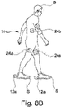
- Fig. 8B shows a perspective view of a patient P equipped with the control system 10 disclosed in Fig. 7 comprising two sensors 12 according to the present invention.
- a patient P is equipped with said control system 10 disclosed in Fig. 7 comprising two sensors 12, which are here two IMUs 12a attached to the shoes S of the patient P.
- one IMU 12a is attached to the left shoe S of the patient P and one IMU 12a Is attached to the right shoe S of the patient P.
- the IMUs 12a are placed on the heel area of the shoes S of the patient P.
- control system 10 comprises also two electrodes 24a for FES.
- one electrode 24a for FES is attached to the left leg of the patient P and one electrode 24a for FES is attached to the right leg of the patient P.
- each leg of the patient P is equipped with two or more electrodes 24a for FES.
- one electrode 24a for FES is attached to the left upper leg of the patient P and one electrode 24a for FES is attached to the right upper leg of the patient P.
- the one or more electrodes 24a for FES are placed at any position(s) of the legs and/or hips and/or trunk of the patient P.
- control system 10 comprises one electrode 24b for EES.
- the electrode 24b for EES is attached to the dorsal roots of the patient P.
- the controller 14 tracks and/or estimates the movement of the foot of the patient P for translating it into stimulation data, based on the estimated movement, being provided by the IPG 18 to the patient P.
- the IPG 18 provides FES via the lead 20 and the electrode module 24 with the one or more electrodes 24a.
- the IPG 18 provides EES via the lead 20 and the electrode module 24 with the one or more electrodes 24b.
- the IMUs 12a could be placed at and/or inserted in, and/or integrated in different positions in the shoe S or in the shoe sole and/or in the shoe Insole.
- control system 10 could comprise only one IMU 12a positioned directly or indirectly to the left foot or the right foot, or the left shoe S or the right shoe S of the patient P.
- a patient P equipped with the control system 10 disclosed in Fig. 7 could be equipped with two or more sensors 12 for each foot and/or leg, cf. also Fig. 8C .
- a patient equipped with the control system 10 disclosed in Fig. 7 could be equipped with more sensors 12 located on a chain, e.g. from hip to foot via thigh, knee and shank.
- two or more sensors 12 can be located on a chain from head to toes.
- a shoe S and/or a shoe sole and/or a shoe insole could be equipped with two or more sensors 12.
- Said sensors 12 may be positioned at any place from the distal end to the proximal end of the foot, in particular in the heel area and/or the metatarsal area and/or the toe area, and/or the sides of the feet.
- the one or more sensor(s) 12 could be part of and/or inserted and/or integrated into and/or onto an exoskeleton, tights, a belt, straps, a stretching band, a knee sock, a sock and/or a shoe S of the patient.
- socks and tights consist of or comprise a piezoelectric textile sensor integrated in the trunk, waist, hip, knee, heel and/or toe area.
- socks or tights could be equipped with electrodes and/or electro conductive yam.
- magnetic sensors and magnetic field sensors could be incorporated in shoes S for walking on a magnetic sensor plate or inserted in the treadmill or gait phase detection device.
- the magnetic force could be detected and acquired by magnetic sensors under training, e.g. gait training.
- the one or more sensors 12 could be inserted and/or integrated into and/or onto clothing or the like for the upper body, the trunk and/or arms, and or hands, including but not limited to a top, a longsleeve, a pullover, a jacket, one or more arm sleeves, gloves, and/or one or more armlets.
- the electrodes 24a for FES could also be configured and arranged for foot and/or leg cramp stimulation to release cramp and/or detection of foot and/or leg cramp.
- Fig. 8B stimulating motion of one or more limbs and/or one or more parts of a limb does not necessarily require stimulating on the locomotor system of one or more limbs and/or one or more parts of the limb, respectively, directly.
- the spinal cord or the upper leg may be stimulated to induce a reflex and/or motion of the foot.
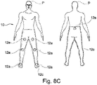
- Fig. 8C shows a perspective view of a patient equipped with the control system 10 disclosed in Fig.7 comprising seven sensors 12.
- a patient P is equipped with said control system 10 disclosed in Fig. 7 comprising seven sensors 12, which are here seven IMUs 12a.
- the seven IMUs 12a build a sensor network 12c.
- the seven IMUs 12a are attached to the lower body of the patient P.
- one IMU 12a is placed centrally In the hip area, whereas the left leg is equipped with three IMUs 12a placed on the foot, the lower leg, and the upper leg, and whereas the right leg is equipped with three IMUs 12a, placed on the foot, the lower leg, and the upper leg, respectively.
- IMUs 12a along the legs and/or feet and/or the lower body could be generally possible.
- IMUs 12a or other sensor 12 types, along the body and/or parts of the body, e.g. the head, the neck, the trunk and/or one or both arms and/or one or both hands could be generally possible.
- both FES and EES can be provided by the IPG 18, the lead 20 and the electrode module 24 with respective electrodes 24a and 24b.
- Fig. 8D shows a perspective view of a sensor insole according to the present invention.
- various sensors 12 are integrated into a sensor insole 300 of a shoe S of a patient P.
- the sensors 12 are pressure sensors 12b.
- eight pressure sensors 12b are incorporated in a sensor insole 300 of a shoe S of a patient P.
- the eight pressure sensors 12b are distributed from the distal end di of a sensor insole 300 to the proximal end pr of a sensor insole 300 of a shoe S of a patient.
- the eight pressure sensors 12b are distributed along the heel area, the metatarsal area, and the toe area of the sensor insole 300.
- two pressure sensors 12b are placed in the heel area, two pressure sensors 12b are placed in the toe area and four pressure sensors 12b are placed in the metatarsal area of the sensor insole 300.
- both shoes S of a patient P could be equipped with sensor insoles 300.
- the sensor insoles 300 provide a precise map of the foot force.
- the pressure sensors 12b in the sensor insole 300 provide a precise description of the gait phase and cadence, e.g. pre-swing, swing, loading response and/or stance (or alternatively swing, stance, toe-off, midswing, heel strike, flat foot, midstance and/or heel-off) can be identified for one foot by analyzing sensor data obtained from one sensor insole 300 of a shoe S.
- the same events and parameters can be identified for the other foot of the patient P by using a second sensor Insole 300.
- the sensor stream is transmitted to the controller 14 according to the disclosure of Fig. 7 .
- 1-7 or more than 8 pressure sensors 12b are integrated in a sensor insole 300 of a shoe S of a patient P.
- the sensor insole 300 itself is a pressure sensor 12b.
- Fig. 8E shows a perspective view of a patient equipped with the control system disclosed in Fig. 7 comprising one IMU and one pressure insole for each foot of the patient according to the present invention.
- a patient P is equipped with the control system 10 disclosed in Fig. 7 including one IMU 12a placed on the left shoe S and one IMU 12a placed on the right shoe S of a patient P as disclosed in Fig. 8B and one sensor insole 300 as disclosed in Fig. 8D for the left shoe S of the patient P and one sensor insole 300 as disclosed in Fig. 8D for the right shoe of the patient P.0
- the sensor insoles 300 for both shoes of the patient P comprise eight pressure sensors 12b (only exemplarily shown in Fig. 8D ).
- a patient P could be equipped with the control system 10 described in Fig. 7 including one IMU 12a and one respective sensor insole 300 for the left or the right foot.
- the IMU 12a and/or the sensor insole 300 can be replaced by another type of sensor 12 including but not limited to e.g. a piezo element.
- the piezo element is integrated in wearables like e.g. a sock, a knee sock, tights, a shoe.
- Fig. 9 shows a schematical view of a patient P and a trainer T (rehabilitation specialist) according to the present invention.
- the patient P and the trainer T are each equipped with one control system 10 disclosed in Fig. 7 .
- control system 10 of the patient P and the control system 10 of a trainer T are interconnected.
- connection between the control system 10 of the patient P and the control system 10 of the trainer T is established by a wireless link WL.
- step high or step size could generally be transferred from the control system 10 of the trainer T to the control system 10 of the patient P.
- control system 10 of the trainer T functions as reference for open-loop stimulation of the patient P by the control system 10 of patient P.
- control system 10 of trainer T could function as reference for closed-loop stimulation of the patient P by the control system 10 of patient P.
- gait events toe-off, midswing, heel strike, flat foot, midstance and/or heel-off, or alternatively pre-swing, swing, loading response and/or stance
- gait events toe-off, midswing, heel strike, flat foot, midstance and/or heel-off, or alternatively pre-swing, swing, loading response and/or stance
- said synchronization could enable identifying and/or evaluating and/or correcting for the difference(s) between the healthy, regular and physiological movement of the trainer T and the impaired and irregular movement of the patient P.
- the tracking and estimating could be performed online and/or in real-time and/or with time delay.
- Fig. 9 Not shown in Fig. 9 is the fact that the patient P, the trainer T or the one or more further patients could be equipped with a training apparatus, e.g. an exoskeleton 22a, a robot, a treadmill, a cycling machine and/or a body weight support system or the like, as disclosed in Fig. 8A .
- a training apparatus e.g. an exoskeleton 22a, a robot, a treadmill, a cycling machine and/or a body weight support system or the like, as disclosed in Fig. 8A .
- Fig. 10 shows a schematical view of a patient P and a remote trainer T1 according to the present invention.
- a patient P is equipped with said control system 10 disclosed in Fig. 7 and located at location L.
- a remote trainer T1 is equipped with said control system 10 disclosed in Fig. 7 and located at location L1 remote from the location L of the patient P.
- control system 10 of a patient P and the control system 10 of a remote trainer T1 are interconnected.
- connection between the control system 10 of the remote trainer T1 and the control system 10 of the patient P is established by a wireless link WL.
- the two or more patients differ in terms of progress in the rehabilitation process.
- the tracking and estimating is performed online and in real-time.
- Fig. 10 Not shown in Fig. 10 is that it could be generally possible, that the one or more patients P watch the remote trainer T1 and vice versa - via e.g. a standard screen, a beamer, a computer, a laptop, a tablet computer, or a mobile phone.
- a standard screen e.g. a beamer, a computer, a laptop, a tablet computer, or a mobile phone.
- the patient P and the remote trainer T1 communicate with each other via a general telecommunication device.
- controller may in general allow that tracking and estimating is performed from one patient to another patient.
- Fig. 10 Not shown in Fig. 10 is that it could be generally possible, that the one or more patients P and the remote trainer T1 communicate within an augmented and/or virtual reality module as described for the embodiment in Fig. 7 .
- Fig. 11 shows a flow chart of the offline workflow of a control system for a movement reconstruction and/or restoration system for a patient according to the present invention.
- the offline workflow 100 for the control system 10 for a gait reconstruction and/or restoration system for a patient P as disclosed in Fig. 7 and Fig 8A comprises the steps S101-S106.
- starting step S101 the one or more sensors 12 or the one or more sensor networks measure sensor data for a period of time of minimum one complete movement cycle.
- the movement cycle could be a gait cycle.
- the movement cycle could be a swim or row cycle, or standing up, or sitting down.
- the movement cycle could be any other movement.
- step S102 the sensor data are transferred to the controller 14.
- step S103 accumulated sensor data for the recorded period of time are stored in the sensor data buffer of the controller 14.
- step S104 based on the accumulated sensor data for the recorded period of time in the sensor data buffer, the controller 14 determines a list of different movement events and phase offline.
- gait events could include but are not limited to initial ground contact, heel strike, foot flat, loading response, midstance, terminal stance, heel off, preswing, toe off, initial swing, midswing, terminal swing, and/or heel strike (or e.g. pre-swing, swing, loading response, stance).
- a movement model for the recorded movement events is created in step S105.
- step S106 stimulation of the patient is performed.
- the controller 14 programs the IPG 18 to deliver the correct stimulation via the lead 20 according to the movement model determined offline by the controller 14.
- the movement phase always takes the same value at the same event.
- Performing the tracking and estimating offline may allow to use criteria that could not be used on real-time.
- the sensor data buffer of the controller 14 could comprise accumulated sensor data from one patient P, and/or from two or more patients P.
- the sensor buffer could comprise accumulated sensor data from one or more trainers T and/or one or more healthy subjects.
- Fig. 11 Not shown in Fig. 11 is that recorded sensor data could be preprocessed using a Kalman filter.
- Fig. 12 shows a flow chart of the online workflow of a control system for a movement reconstruction and/or restoration system for a patient according to the present invention.
- the online workflow 200 for the control system 10 for a movement reconstruction and/or restoration system for a patient P as disclosed in Fig. 7 and Fig 8A comprises the steps S201-S206.
- one or more sensors 12 or one or more sensor networks measure sensor data.
- step S202 the sensor data are transferred from the sensor 12 to the sensor data buffer of the controller 14.
- step S203 sensor data for the recorded period of time are stored online in the sensor data buffer of the controller 14.
- the sensor data buffer is always updated online by recent sensor data from the sensor(s) 12.
- step S204 the controller 14 determines a list of different movement events and phase for all recorded movement events.
- possible movement events could include but are not limited to initial ground contact, heel strike, foot flat, loading response, midstance, terminal stance, heel off, preswing, toe off, initial swing, midswing, terminal swing, and/or heel strike.
- Various sensor data inputs from the sensor(s) 12 update the sensor data buffer and as soon as a whole movement, e.g. gait cycle, is detected, the past movement event, e.g. gait event, is determined online.
- step 205 the controller 14 trains the movement model using recent accumulated sensor data to adapt the particular movement of the patient P.
- step S206 stimulation of the patient P is performed according to the movement model.
- the controller 14 programs the IPG 18 to deliver the correct stimulation via the lead 20 according to the recent movement model determined online by the controller 14.
- the online workflow 200 realizes a real-time solution and a real-time data transfer.
- the general movement model used for fusing with recent sensor data could be based on accumulated sensor data from one patient P, and/or from two or more patients P.
- the general movement model used for fusing with recent sensor is based on sensor data from one or more trainers T and/or one or more healthy subjects.
- the filter could be a Kalman filter.
- the online workflow 200 could also be used for a control system 10 for a movement reconstruction and/or restoration system for diverse movements including e.g. walking, running, cycling, swimming, rowing, standing up, sitting down.
- Fig. 13 shows a schematical diagram of foot pitch/forward acceleration of a patient P equipped with the control system disclosed in Fig.7 .
- the patient P is equipped with one IMU 12a per foot.
- the patient P could be equipped with the control system 10 described in Fig. 7 including one IMU 12a and one respective sensor Insole 300 for the left or the right foot.
- the patient P could be equipped with two or more IMUs 12a per foot.
- the IMU 12a and/or the sensor insole 300 can be replaced by another type of sensor 12 including but not limited to e.g. a piezo element.
- the piezo element is integrated in wearables like e.g. a sock, a knee sock, tights, a shoe.
- gait phase and cadence information of both feet of the patient P together with the gait phase and cadence of the stimulation input, a reliable gait phase and cadence estimate can be provided.
- gait can vary a lot between different patients P as well as for a single patient P for different walking speeds and different assistive devices (body-weight support, walker, crutches, etc.).
- machine-learning methods can be used to adapt the gait phase estimation to the specific gait of the patient P.
- the level of agreements and discrepancies between motion of the left and right foot, and the stimulation input can be used to give an indication of the gait phase estimation reliability, e.g., the measured cadence of the left foot should be equal to the measured cadence of the right foot and the cadence of the provided stimulation, and the left foot and right foot should be (roughly) in anti-phase.
- inhibitory reflex circuits in the spinal cord modulate neural firing rates (and hence modulate recruitment of motor neurons through EES).
- control and estimation routines included herein can be used with various system configurations.
- the control methods and routines disclosed herein may be stored as executable instructions in non-transitory memory and may be carried out by a control system 10 e.g. as a part of the controller 14 in combination with the sensors 12, the programmer 16, the stimulation system 18, the lead 20, and other system hardware.
- the specific routines described herein may represent one or more of any number of processing strategies such as event-driven, interrupt-driven, multitasking, multi-threading, and the like. As such, various actions, operations, and/or functions illustrated may be performed in the sequence illustrated, in parallel, or in some cases omitted.
Landscapes
- Health & Medical Sciences (AREA)
- Life Sciences & Earth Sciences (AREA)
- General Health & Medical Sciences (AREA)
- Engineering & Computer Science (AREA)
- Animal Behavior & Ethology (AREA)
- Veterinary Medicine (AREA)
- Public Health (AREA)
- Biomedical Technology (AREA)
- Biophysics (AREA)
- Radiology & Medical Imaging (AREA)
- Nuclear Medicine, Radiotherapy & Molecular Imaging (AREA)
- Heart & Thoracic Surgery (AREA)
- Surgery (AREA)
- Molecular Biology (AREA)
- Medical Informatics (AREA)
- Physics & Mathematics (AREA)
- Pathology (AREA)
- Neurology (AREA)
- Physical Education & Sports Medicine (AREA)
- Physiology (AREA)
- Neurosurgery (AREA)
- Cardiology (AREA)
- Orthopedic Medicine & Surgery (AREA)
- Vascular Medicine (AREA)
- Rehabilitation Therapy (AREA)
- Pain & Pain Management (AREA)
- Epidemiology (AREA)
- Dentistry (AREA)
- Computer Networks & Wireless Communication (AREA)
- Oral & Maxillofacial Surgery (AREA)
- Computer Vision & Pattern Recognition (AREA)
- Psychiatry (AREA)
- Signal Processing (AREA)
- Artificial Intelligence (AREA)
- Rehabilitation Tools (AREA)
- Electrotherapy Devices (AREA)
Description
- The present disclosure relates to a system for controlling a movement reconstruction and/or restoration system for a patient, e.g. in the field of improving recovery after neurological disorders like spinal cord injury (SCI), for example after trauma. Decades of research in physiology have demonstrated that the mammalian spinal cord embeds sensorimotor circuits that produce movement primitives (cf. Bizzi E., et al., Modular organization of motor behavior in the frog's spinal cord. Trends in ); Levine A. J. et al., Identification of a cellular node for motor control pathways. Nature neuroscience 17, 586-593 (2014)). These circuits process sensory information arising from the moving limbs and descending inputs originating from various brain regions in order to produce adaptive motor behaviors. A spinal cord injury (SCI) interrupts the communication between the spinal cord and supraspinal centres, depriving these sensorimotor circuits from the excitatory and modulatory drives necessary to produce movement.
- A series of studies in animal models and humans showed that electrical neuromodulation of the lumbar spinal cord using epidural electrical stimulation (EES) is capable of (re-)activating these circuits. For example, EES has restored coordinated locomotion in animal models of SCI, and isolated leg movements in individuals with motor paralysis (cf. van den Brand R., et al., Restoring Voluntary Control of Locomotion after Paralyzing Spinal Cord Injury. Science 336, 1182-1185 (2012 ); Angeli CA. et al., Altering spinal cord excitability enables voluntary movements after chronic complete paralysis in humans. Brain: a journal of neurology 137, 1394-1409 (2014 ); Harkema S. et al., Effect of epidural stimulation of the lumbosacral spinal cord on voluntary movement, standing, and assisted stepping after motor complete paraplegia: a case study. The Lancet 377, 1938-1947 (2011 ); Danner SM. et al., Human spinal locomotor control is based on flexibly organized burst generators. Brain: a journal of neurology 138, 577-588 (2015 ); Courtine G. et al., Transformation of nonfunctional spinal circuits into functional states after the loss of brain input. Nature neuroscience 12, 1333-1342, (2009 ); Capogrosso M. et al., A brain-spine interface alleviating gait deficits after spinal cord injury in primates. Nature 539, 284-288 (2016 )).
-
EP 2 868 343 A1 -
WO 2002/034331 A2 discloses a non-closed loop implantable medical device system that includes an implantable medical device, aong with a transceiver device that exchanges data with the patient, between the patient and the implantable medical device, and between a remote location and the implantable medical device. A communication device coupled to the transceiver device exchanges data with the transceiver device, the implantable medical device through the receiver device, and between the transceiver device and the remote location to enable bi-directional data transfer between the patient, the implantable medical device, the transceiver device, and the remote location. A converter unit converts transmission of the data from a first telemetry format to a second telemetry format, and a user interface enables information to be exchanged between the transceiver device and the patient, between the implantable medical device and the patient through the transceiver device, and between the patient and the remote location through the transceiver device. -
EP 3 184 145 A1 -
EP 2 652 676 A1 relates to a gesture control for monitoring vital body signs and reuses an accelerometer, or, more precise, sensed accelerations of a body sensor for user control of the body sensor. This is achieved by detecting predefined patterns in the acceleration signals that are unrelated to other movements of the patient. These include tapping on/with the sensor, shaking, and turning the sensor. New procedures are described that make it possible to re-use the acceleration sensing for reliable gesture detection without introducing many false positives due to non-gesture movements like respiration, heartbeat, walking, etc. Similar solutions for tapping detection of a user are known fromUS 8,326,569 andUS 7,742,037 . -
WO 2007/047852 A2 discloses systems and methods for patient interactive neural stimulation and/or chemical substance delivery. A method in accordance with one embodiment of the invention includes affecting a target neural population of the patient by providing to the patient at least one of an electromagnetic signal and a chemical substance. The method can further include detecting at least one characteristic of the patient, which is correlated with the patient's performance of an adjunctive therapy task that is performed in association with affecting the target neural population. Further, this method can include controlling at least one parameter in accordance with which the target neural population is affected, based at least in part on the detected characteristic. -
WO 2017/062508 A1 discloses a system for controlling a therapeutic device and/or environmental parameters including one or more body worn sensor devices that detect and report one or more physical, physiological, or biological parameters of a person in an environment. The sensor devices can communicate sensor data indicative of the physical, physiological, or biological parameters of a person to an external hub that processes the data and communicates with the therapeutic device to provide a therapy (e.g., neuromodulation, neurostimulation, or drug delivery) as a function of the sensor data. -
US 2018/117318 A1 discloses a neuro-prosthetic system for closed-loop operation of neuro-prosthetic stimulator, has controller that is configured to adjust triggered electrical stimulation events based on output of calibrated motor movement command model.US 2018/280700 A1 discloses a system for providing neuromodulation and/or neuro-stimulation by central nervous stimulation and peripheral nervous system stimulation, has peripheral nervous system stimulation module for providing stimulation result.US 2011/092882 discloses a patient interactive neural stimulation method for treating neurologic dysfunction, involves detecting characteristics of patient, correlated with patients performance of adjunctive therapy task. - According to the state of the art, voluntary control of movement still cannot be achieved by the subject. It is important to keep in mind that the patient is not a robot and can and should not be stimulated and controlled as a robot. Therefore, there is a lack to have a system which overcomes the drawbacks of the prior art. In particular, there is the need of a system stimulating the patient not as a robot. The goal of applying stimulation is not to control the patient, but to support the patient during training and daily life activities. Hence, a control system should support the patient's own natural control loop composed of the brain, nervous system, and sensory organs. This means that said control system should not e.g. adjust the stimulation parameters to force the patient's lower body motion to a given reference trajectory. Instead, the patient should be able to determine e.g. the walking cadence.
- It is an object of the present invention to improve a neurostimulation system, e.g. In the field of improving recovery after neurological disorders like spinal cord injury, for example after trauma, especially in adding a control system for a movement reconstruction and/or restoration system for a patient.
- This object is solved according to the present invention by a control system for a movement reconstruction and/or restoration system for a patient, with the features of
claim 1. Accordingly, a system for a movement reconstruction and/or restoration system for a patient, comprising - at least one sensor,
- at least one controller,
- at least one programmer,
- at least one stimulation system,
- create and/or guide a movement model for a patient and/or
- adjust stimulation settings based on sensor input,
- The invention is based on the basic idea that in the context of neuromodulation, especially neurostimulation, the electrical stimulation parameters defining the stimulation in a movement reconstruction and/or restoration system for a patient can be controlled with said system, wherein a training entity is used, which is not the patient himself or herself, but another entity. By this, a more defined or even a remote training and rehabilitation is possible. The use of a general hardware concept and sensors being part of or being attached to a training entity combined into one strategy and made available for a patient being equipped with the system allow to support limbs, e.g. lower limbs motor function of patients with complete or incomplete SCI to enable rehabilitation training and facilitate daily life activities. The training entity defines movement, including but not limited to gait phase in terms of kinematics of the body and/or parts of the body, e.g. lower body (legs and feet), upper body (trunk, head, arms, hands). Hence, to estimate the movement, body kinematics need to be determined.
- To estimate the gait phase, in particular the lower body kinematics need to be determined. This can be done directly by attaching sensors to the body and/or parts of the body including but not limited to parts of the trunk and/or abdomen and/or the limbs and/or part of the limbs or indirectly by measuring muscle activation or by measuring the interaction between the body and/or parts of the body, e.g. limbs and/or part of the limbs and their surroundings (e.g. the ground reaction forces or upper body motion). Based on this, the system enables stimulating the spinal cord at the correct place and at the correct time while the patient is performing different tasks. This means that the control system does not e.g. adjust the stimulation parameters to force the patient's body and/or limb(s) motion to a given reference trajectory.
- Moreover, the general feeling and well-being (e.g. pain treatment) of the patient can be enhanced.
- The programmer is an application installed on a mobile device that communicates with the controller. The programmer is used by the therapist, physiotherapist, or patient to provide inputs to the controller, e.g., selecting, starting, and stopping a task or configuring stimulation parameters.
- The programmer should allow adjusting the stimulation parameters of a task, while the task is running. This enables the user to tune the stimulation without having to start and stop the task, which would be very cumbersome at the start of the rehabilitation training, when all stimulation partitures are developed and tuned.
- The programmer includes but is not limited to a physiotherapist programmer (PTP), and patient programmer (PP) which are applications installed on a mobile device that communicate with the controller.
- Neural stimulation may be achieved by electrical stimulation, optogenetics (optical neural stimulation), chemical stimulation (implantable drug pump), ultrasound stimulation, magnetic field stimulation, mechanical stimulation, etc.
- Known electrical stimulation systems use either Central Nervous System (CNS) stimulation, especially Epidural Electrical Stimulation (EES), or Peripheral Nervous System (PNS) Stimulation, especially Functional Electrical Stimulation (FES).
- Epidural Electrical Stimulation (EES) is known to restore motor control in animal and human models and has more particularly been shown to restore locomotion after spinal cord injury by artificially activating the neural networks responsible for locomotion below the spinal cord lesion ( Capogrosso, M., et al., A Computational Model for Epidural Electrical Stimulation of Spinal Sensorimotor Circuits, Journal of Neuroscience , 33 (49), 19326-19340 (2013 ); Courtine G., et al., Transformation of nonfunctional spinal circuits into functional states after the loss of brain input, Nat Neurosci. 12(10), 1333-1342 (2009 ); Moraud EM., et al, Mechanisms Underlying the Neuromodulation of Spinal Circuits for Correcting Gait and Balance Deficits after Spinal Cord Injury, Neuron, 89(4), 814-828 (2016 )). EES does not directly stimulate motor-neurons but the afferent sensory neurons prior to entering into the spinal cord. In this way, the spinal networks responsible for locomotion are recruited indirectly via those afferents, restoring globally the locomotion movement by activating the required muscle synergies.
- Peripheral Nervous System (PNS) Stimulation systems used to date in the clinic are known as Functional Electrical Stimulation (FES) that provides electrical stimulation to target muscles with surface electrodes, either directly through stimulation of their motorfibers (neuro-muscular stimulation), or through a limited set reflexes (practically limited to the withdrawal reflex) or by transcutaneously stimulating the peripheral nerves. The resulting muscle fatigue has rendered FES unsuitable for use in daily life. Furthermore, successes have remained limited through cumbersome setups when using surface muscle stimulation, unmet needs in terms of selectivity (when using transcutaneous nerve stimulation) and a lack of stability (impossible to reproduce exact electrode placement on a daily basis when stimulating muscles, moving electrodes due to clothes, sweating).
- It is possible to provide neuromodulation and/or neurostimulation with the system to the CNS with a CNS stimulation system and/or to the PNS with a PNS stimulation system. Both CNS and PNS can be stimulated at the same time or also intermittently or on demand. These two complementary stimulation paradigms can be combined into one strategy and made available for a patient being equipped with the system. For example, neuromodulation and/or neurostimulation of the CNS may be used to enhance and/or the patient's capabilities of movement, especially in a way that the existing ways of physiological signal transfer in the patient's body is supported such that the command signals for body movement or the like still are provided by the patient's nervous system and just supported and/or enhanced or translated by the CNS stimulation system. The stimulation provided by the PNS system may be used to specifically steer and direct stimulation signals to specific peripheral nervous structures in order to trigger a specific movement and/or refine existing movements. Such a PNS stimulation may be used to refine and/or complete motion and/or the patient's capabilities of movement. It can be e.g. used to complete flexion or extension, lifting, turning or the like of inter alia but not limited to toes, fingers, arms, feet, legs or any extremities of the patient. This can be e.g. done in cases where it is realized that the neuromodulation and/or neurostimulation provided by the CNS stimulation system is not sufficient to complete a movement or intended status of the patient. Then, such a movement or intended status may be completed or supported by stimulation provided by the PNS stimulation system. The PNS stimulation can be also used to reduce side effects or compensate for imprecisions of the CNS stimulation.
- EES can be phasic or tonic, selective PNS is always phasic. Phasic is defined as locked to defined events in the sensing signals (decoded intention, continuous decoding, muscle activity onset, movement onset, event during defined movement (foot off or foot strike during gait for instance).
- By PNS stimulation, a stimulation of the upper limb nerves, i.e. the radial, ulnar and/or median nerves can be provided. Also, the lower limb nerves like the sciatic and/or femoral nerves can be provided in by PNS stimulation. All PNS stimulation can be done by targeting one of the above-mentioned nerves with intra-neural electrodes (transversal or longitudinal) or epi-neural (cuff) electrodes.
- By CNS stimulation the following nervous structures may be stimulated: for the upper limb movements the cervical spinal cord or hand/arm motor cortex may be stimulated with the CNS stimulation system. For the lower limb movements, the lumbosacral spinal cord may be stimulated. All these nerves can be targeted with epidural, subdural or intra-spinal/intra-cortical stimulation.
- Both PNS and CNS stimulation systems may comprise implantable pulse generators (IPGs). IPGs can be used for providing the necessary stimulation current and signals for the CNS stimulation system and the PNS stimulation system.
- The IPG produces the stimulation pulses that are delivered by a lead with multiple electrodes to the stimulation side, e.g. spinal cord. For EES, the lead is positioned in the epidural space (i.e. on the outside of the dural sac, which encases the spinal cord and the cerebrospinal fluid in which the spinal cord 'floats'), on top of the spinal cord (including, but not limited to the segments T12, L1, L2, L3, L4, L5, and S1 bilaterally).
- It is also possible that two separated IPGs are provided, one for the PNS stimulation system and one for the CNS stimulation system.
- It is also possible that external stimulators are used, especially for PNS stimulation. The stimulation parameters for the PNS stimulation and the EES stimulation may be frequency, amplitude, pulse-width and the like.
- The system may support open-loop or closed-loop stimulation modes. Open-loop stimulation may be performed where a pre-defined fixed stimulation Is executed without adapting to e.g. the motion of the patient. The stimulation settings (i.e. electrode configuration - that means stimulation delivery by which electrode to stimulate which functional muscle block at which times, frequencies, and amplitudes) are determined completely by the therapist or physiotherapist and/or field engineer and/ or algorithmically. The control system may interfere with the natural feedback loop of the patient to enable smooth motion, e.g. a regular gait cycle comparable to a healthy subject. Closed-loop walking may be performed, where feedback is used to adjust the stimulation to the gait of the patient. Closed-loop cycling may be performed, where feedback is used to adjust the stimulation to the cycling phase of the patient. The interfaces wireless sensor network WSN (wireless link between the sensors and the controller), communication COM (wireless link between a programmer and the controller), and telemetry TEL (wireless link between the stimulation system and the controller) connect the various subsystems in the control loop.
- Programmers are mobile devices, the stimulation system is implanted In the body, the controller is body-worn, and the sensors are attached to the patient's body and/or one or more parts of the patient's body and/or the patient's limbs/feet or to a bicycle crank and/or to any other training apparatus for any other type of movement, including but not limited to rowing, stepping and/or swimming. Hence, these interfaces all need to be wireless.
- The training entity may be a trainer and/or physiotherapist.
- In particular, the shoe of the patient and/or physiotherapist may be equipped with sensors. Said sensors may be placed on top of the instep of the shoe, and/or at the back of the heel and/or below the heel of the shoe (e.g. in a pocket in the sole of the shoe or as an inlay sole) of the patient and/or physiotherapist.
- Moreover, the training entity may be or may comprise a training apparatus, wherein the apparatus is at least one of an exoskeleton, a robot, a treadmill, a cycling machine and/or a body weight support system. In particular, the trainer of the patient and/or subject may be equipped with at least one sensor or more sensors.
- The controller may be configured and arranged for tracking and estimating the training entity movement and for translating it into stimulation data, based on the estimated movement, being provided by the stimulation system to the patient for the patient training for movement reconstruction and/or restoration.
- In particular, the controller is a body-worn platform to execute the control software. The controller processes data that is acquired among others from the sensor, the stimulation system, and the programmer, and programs the stimulation system to deliver the correct stimulation.
- Furthermore, the controller may be configured and arranged that the tracking and estimating of the movement is performed online and/or offline.
- Online tracking and estimating helps to realize a direct transfer of the training entity movement and for translating it into stimulation data being provided by the stimulation system to the patient for the patient training for movement reconstruction and/or restoration. It Is helpful to realize a real-time solution and a real-time data transfer.
- Here, real-time is defined as an end-to-end latency that is less than 100ms, preferably less than 50ms.
- Offline configuration by doing the tracking and estimating process offline may allow the controller to program the stimulation system based on recorded sensor data for a period of time of minimum one complete movement, e.g. gait cycle. Performing the tracking and estimating offline may allow to use criteria that could not be used on real-time.
- The movement model may be created so that the movement phase takes always the same value at the same event. Using robust criteria that is common to all kind of healthy or pathological movement, this may allow to determine different movement events offline on recorded data.
- At the beginning of a rehabilitation session, the movement model used Is a general movement model trained on a set of different subjects, the movement model, e.g. gait model is thus not perfect but sufficient to make some steps. Everything is recorded in parallel of the analysis in a sensor buffer. As soon as a whole movement cycle, e.g. gait cycle, is detected, an online expert system determines the past movement event, e.g. gait event, and the movement model is trained to adapt to the new data. Then the movement model used online is updated.
- It may be possible to stop the learning process when the movement model is good enough and to store it for further sessions with the same patient.
- Onsite tracking and estimating of a patient's movement may allow tracking and estimating the patient him or herself. Remote tracking and estimating of the movement may allow that the movements of a training entity and/or patient and/or physiotherapist are copied to more patients at the same time.
- In particular, the controller may allow that tracking and estimating is performed from one patient to another patient. This can be realized for example by transferring the settings from one patient to another patient. In particular, the settings used for one patient can be used for the treatment of another patient. Especially, settings from a healthy person can be used for the treatment of a patient.
- In particular, the controller may allow that tracking and estimating is performed and/or transferred from one patient advanced in the rehabilitation process to patients less advanced.
- Moreover, the controller may be configured and arranged that the tracking and estimating is performed online and/or in real-time and/or with time delay.
- Apart from applying the correct electrical field at the right location, the stimulation needs to be applied at the correct moments in time and correctly sequenced. It may be very helpful for the patient equipped with the system to have stimulation at the moment or close to the moment needed to proceed e.g. with the desired movement. The patient needs to be able to predict when the stimulation will occur in order to make the best use of the stimulation. Likewise, suppressing motion while stimulation is provided also requires that the patient knows when to expect the stimulation. When the stimulation is not synchronized to the patient's (intended) motion, the patient is not able to perform a proper movement. This means that the stimulation needs to be predictable by the patient, as the patient needs to synchronize to the stimulation.
- In particular, real-time may be understood in a way that the delay between sense signals and provided stimulation signals shall be not more than 30ms (see also
WO 2016/0279418 A1 - There is a delay from neural stimulation (e.g. the spinal cord) to muscle activation. In particular, delay values are differing depending on the type of muscle. The controller may be adapted to this kind of different signal delay.
- There may be at least two or more sensors forming a sensor network, wherein at least one of the two or more sensors is connected to the controller.
- Using a sensor network of two or more sensors, limb position estimates, e.g. lower limb position estimates can be obtained by double integration of the measured acceleration in combination with drift correction. However, also position estimates of the trunk and/or head can be obtained. In this way, non-real-time reconstruction of limb and/or part of a limb and/or trunk and/or head trajectories may be done up to a few centimeters accuracy for healthy subjects. In particular, movement, e.g. gait phase and cadence may be estimated using two sensors.
- In particular, two or more sensors may be placed on one foot and/or another part of a leg, including but not limited to the shank and/or thigh and/or hip and/or other parts of the body including but not limited to the trunk, and/or one or two arms and/or one or two hands and/or another part of an arm and/or the head and/or the neck of the patient to provide a precise description of the movement.
- More sensors may display different topologies, including but not limited to star network, body network, chain network. Using more sensors located on a chain, e.g. from hip to foot via upper leg, knee and lower leg the relative positions of all leg joints and therefore, the complete kinematics of the lower body, including foot trajectories, but also knee and hip angles may be reconstructed. In general, more sensors can be located on a chain from head to toes to determine body kinematics.
- The relative position estimates may be drift-free.
- The control system may further comprise an augmented and/or virtual reality module, which is configured and arranged to provide information related to movement reconstruction and/or restoration, especially information related to the training to be performed or being performed for movement reconstruction and/or restoration.
- By simulating real-life activities, the patient may be able to perform rehabilitation training in a setting that is usually impossible to create in a hospital environment.
- In particular, the augmented and/or virtual reality module may be designed to aid the rehabilitation process and track the patient's progress. The augmented and/or virtual reality module may improve e.g. coordination, balance, muscle strength, range of motion, reaction times, memory.
- Augmented and/or virtual reality modules may use different technologies including virtual reality headsets (including e.g. gyroscopes, accelerometers, structured light systems, eye tracking sensors, etc.), eyeglasses, head-up displays, bionic contact lenses, virtual retinal display, head-mounted display, EyeTrap, handheld displays, spatial augmented reality, etc.
- Moreover, the augmented and/or virtual reality module may be configured and arranged to provide gamification information related to movement reconstruction and/or restoration.
- In particular, the patient's body movements may be transferred to the game world during a rehabilitation session.
- In specific cases, this feature may motivate and affect positively the progress of regaining by a patient control of his or her body and/or parts of his or her body, e.g. the limbs. Syncing the physical body in all its expressive capacity with e.g. a digital avatar may allow the patient to analyze his/ her movement in a respective training environment.
- At least one sensor may be or may comprise at least one of an inertial measurement unit (IMU), an optical sensor, a camera, a piezo element, a velocity sensor, an accelerometer, a magnetic sensor, a torque sensor, a pressure sensor, a displacement sensor, a contact sensor, a EMG measurement unit, a goniometer, a hall sensor and/or a gyroscope and/or motion tracking video camera, or infra-red camera.
- Some sensors may require fixed base station in the environment, including but not limited to magnet sensors or infra-red sensors.
- Electromagnetic position sensors, optical sensors and cameras may estimate 3D position and orientation.
- In particular, magnetic sensors and magnetic field sensors may be incorporated in shoes for walking on a magnetic sensor plate or inserted in the treadmill or gait phase detection device. The magnetic force may be detected and acquired by magnetic sensors under gait training.
- Torque sensors may be placed on a bicycle crank for assessing the torque during cycling.
- Some sensors may be worn by the patient without acquiring fixed base station, including but not limited to piezo elements, pressure sensors and/or torque sensors.
- Velocity sensors may monitor linear and angular velocity and detect motion. 3D angular velocity may be estimated by 3-axis gyroscope.
- Said IMU may measure and report 3D accelerations, 3D angular velocities and 3D orientation using a combination of one or more of an accelerometer, one or more of gyroscopes, and optionally one or more of a magnetometer. Optionally, a temperature sensor may also be included to compensate for the effect of temperature on sensor readings. By integrating the angular velocity assessed by said one or more gyroscopes and fusing with data from said one or more accelerometers (Kalman filter), it may be possible to get a precise measurement of the movement and/or angle of e.g. the shank, thigh, foot, arm, and/or hand and/or trunk and/or head. This movement and/or angle may have a regular and characteristic pattern for healthy subjects but not for an injured patient. Based on these measurements the orientation of the IMU with respect to the fixed world can be estimated accurately, using standard sensor fusion algorithms.
- To estimate the movement, e.g. gait phase, the (lower) body kinematics need to be determined. The sensors collect motion data, based on which the movement phase, e.g. gait phase or pedal phase is determined in real-time. This can be done directly by attaching sensors to the training entity and/or by the sensor being part of a training entity, or indirectly by measuring muscle activation or by measuring the interaction between the body and/or parts of the body and its/their surroundings and/or by attaching sensors to the body of the patient (e.g. to the head and/or the neck and/or the trunk and/or one or more limbs and/or one or more parts of the limbs). So, the sensor enables to determine movement events, e.g. gait events with criteria that are common to all kind of healthy or pathological gait.
- The acceleration and orientation of the body and/or part of the body, e.g. the hip, thigh, shank, foot, arm, hand, trunk, head may be sampled at a sufficiently high rate and sufficiently low latency, such that the sampled acceleration and orientation known to the system closely may match the true acceleration and orientation of the feet.
- In some embodiments, the sensor setup may work everywhere in daily life, not bound to a specific location (like when using cameras), and may be independent from assistive devices (e.g., body weight support system, walker, crutches, etc.).
- Using a pressure or contact sensor may allow to directly measure the essence of stance which is the weight-bearing phase of gait cycle.
- An EMG measurement unit may sense muscle activity by means of surface or Intramuscular EMG electrodes for flexors and extensors.
- By means of variables like kinematic markers the kinematic of the patient may be sensed directly or Indirectly.
- Sensors may be worn on the legs and/or feet and/or the trunk and/or the head and/or the arms in case of closed-loop walking, or a single sensor is attached to the bicycle crank or to one or both feet of the patient in case of closed-loop cycling.
- Thus, for closed-loop cycling, the stimulation may be determined by the crank angle and/or foot angle.
- Pressure sensors and piezo elements may sense food sole pressure distribution, applied force on the ground and applied torque on bicycle crank during stance phase. Swing and stance phase may be estimated, as well as e.g. foot strike heel-off, toe-off, and applied force.
- Moreover, the training entity may be the patient himself or herself.
- In general, it may be possible that the controller is integrated into the stimulation system. Further, it may be possible that the programmer is integrated in the controller or vice versa.
- Furthermore, the control system may comprise a pre-warning module, which is configured and arranged to provide a pre-warning signal indicative of providing an upcoming stimulation event.
- Regulating the gait to a predefined reference interferes with voluntary motion of the patient. In particular, voluntary motion of the patient may have a large effect on the movement, as the patients voluntary control may modulate muscle activation. The movement pattern may therefore differ from comparable to a healthy subject, to impaired or reduced despite identical stimulation. The pre-warning signal may help the patient to adjust voluntary control to the respective movement planed, thus a regular movement may be performed. The pre-warning signal may be e.g. an audio and/or visual and/or sensory and or haptic signal. The pre-warning signal may include but is not limited to a sound signal, vibration, light signal, smell, taste, pain, temperature (warm, cold), humidity, drought or the like.
- In particular, the pre-warning signal may act in a sub-motor threshold region at which a sensation is evoked, but not a motor response.
- In the following it is identified which control output parameters exist and their effects on the afferent nerves, as well as their end effects on muscle activation is described. Based on this, it may be selected which output parameters will be controlled by the control system.
- Further details and advantages of the present invention shall now be disclosed in connection with the drawings.
- It is shown in
- Fig. 1
- a schematic, very simplified representation of a stimulation pulse delivered by a system according to the present invention;
- Fig. 2A, B
- the necessary current and necessary charge to trigger an action potential in a nerve fiber as a function of the pulse width (using a square pulse);
- Fig. 3
- a table specifying the fiber types, diameter, and function;
- Fig. 4
- the relationship between response delay and inter-muscle response delays;
- Fig. 5
- a table specifying the intended movement and the involved agonist muscle and the involved antagonist muscle;
- Fig. 6
- discrete sets of functional muscle blocks (FMB) and custom muscle blocks (CMB);
- Fig. 7
- a general layout of an embodiment of a control system for a movement reconstruction and/or restoration system for a patient according to the present invention;
- Fig.8A
- a schematical drawing of a patient equipped with an exoskeleton in connection with the embodiment disclosed in
Fig. 7 according to the present invention; - Fig. 8B
- a perspective view of a patient equipped with the control system disclosed in
Fig. 7 comprising two sensors according to the present invention; - Fig. 8C
- a perspective view of a patient equipped with the control system disclosed in
Fig. 7 comprising seven sensors; - Fig. 8D
- a perspective view of a sensor insole according to the present invention; and
- Fig. 8E
- a perspective view of a patient equipped with the control system disclosed in
Fig. 7 comprising one IMU and one pressure insole for each foot according to the present invention. - Fig. 9
- a schematical view of a patient and a trainer (rehabilitation specialist) according to the present invention;
- Fig. 10
- a schematical view of a patient and a remote trainer according to the present invention;
- Fig. 11
- a flow chart of the offline workflow a control system according to the present invention;
- Fig. 12
- a flow chart of the online workflow of a control system according to the present invention; and
- Fig. 13
- a schematical diagram of food pitch/forward acceleration of a patient equipped with the control system disclosed in
Fig. 7 . - Note that in the following we primarily refer to CNS/EES stimulation. The one skilled in the art may transfer the stimulation parameters to PNS/FES stimulation.
- The control system may provide stimulation data for movement reconstruction and/or restoration for stimulation of afferent nerve fibers using electrical current pulses. Given this starting point, the following stimulation parameters may be identified:
- Electrode configuration (which electrodes to use, polarity)
- Stimulation (Pulse) amplitude
- Stimulation (Pulse) width
- Stimulation (Pulse) frequency
-
Fig. 1 illustrates a schematic, very simplified representation of the stimulation pulse, which illustrates the pulse amplitude, pulse width, and pulse frequency. Each stimulation pulse is followed by a neutralization pulse or a neutralization period (not depicted) to remove the electric charge from the tissue in order to avoid tissue damage. - The effects of each of the stimulation parameters are described below.
- Electrode configuration: Stimulating a specific muscle group requires applying a specific electrical field at a specific location on the spinal cord or directly through stimulation of motorfibers (neuro-muscular stimulation), or through a limited set reflexes or by transcutaneously stimulating peripheral nerves. Therefore, in the present control system the electrical stimulation may be delivered e.g. to the spinal cord by a lead with multiple electrodes. The location, shape, and direction of the electrical field that is produced may be changed by choosing a different electrode configuration (which electrodes are used, with which polarity and potential) that is used to deliver the current. Hence, the electrode configuration may determine e.g. to which spinal roots the stimulation is delivered, and therefore which subsequent muscles or muscle groups activity will be reinforced.
- Pulse amplitude and pulse width: In
Fig. 2A and Fig. 2B the necessary current and necessary charge to trigger an action potential in a nerve fiber are shown as a function of the pulse width (using a square pulse) (cf: Merrill DR., et al. Electrical Stimulation of excitable tissue: design of efficacious and safe protocols, J Neuroscl methods 141(2):171-98 (2005 )).Fig. 2A and Fig. 2B also show the rheobase current Irh , which is the current that is required when using infinitely long pulse widths, and the chronaxie time tc , which is the required pulse width at a current of 2Irh . - Although larger currents may be required at smaller pulse widths, the total required charge may decrease with decreasing pulse width, see
Figure 2B . Hence shorter pulses with higher current amplitudes may be energetically beneficial. - For smaller diameter nerves, the current-pulse width curve of
Figure 2A shifts, as smaller diameter fibers may require higher currents. Hence, a higher current may activate more nerve fibers, as also smaller diameter nerve fibers may be activated (until saturation). However, also cross-talk is increased as also more neurons from neighboring roots may be activated. Fortunately, the afferent fibers involved in motor control (fiber types la and lb) may be all relatively large (12-20µm), while the fibers involved in touch, temperature, and pain feedback (which should not be triggered) may be relatively small (0.5-12µm), as depicted inFig. 3 . Hence, with increasing pulse width and/or current amplitude, the type la and lb fibers may be the first to be recruited. This may enable recruiting (most of) the relevant fibers while keeping cross-talk and patient discomfort to a minimum. - Pulse frequency: The pulse frequency may determine the frequency of the action potentials generated in the afferent nerves, assuming sufficient charge is delivered each pulse to trigger the action potentials. As no new action potential can occur in a nerve during the refractory period, the frequency of the triggered action potentials will saturate at high pulse frequencies. This saturation point is generally at around 200Hz for afferent fibers ( Miller JP., et al., Parameters of Spinal Cord Stimulation and Their Role in Electrical Charge Delivery: A Review. Neuromodulation: Technology at the Neural Interface 19, 373-384, (2016 )). However, stimulation at frequencies above the saturation point may still be beneficial, as by increasing frequency the total charge delivered per unit time (i.e. charge per second) can be increased without changing current amplitude or pulse width ( Miller JP., et al., Parameters of Spinal Cord Stimulation and Their Role in Electrical Charge Delivery: A Review. Neuromodulation: Technology at the Neural interface 19, 373-384, (2016 )).
- Pulse positioning: Many tasks, Including walking, require simultaneous activation of multiple muscle groups. Hence, to support these tasks, multiple muscle groups may need to be stimulated simultaneously, each requiring a specific electrical field and pulse frequency. When applied simultaneously, these different electrical fields may interact with each other, potentially leading to unintended and uncontrolled effects. Therefore, to avoid this situation, care should be taken that the individual stimulation pulses and their neutralization periods targeting different muscle groups are not applied simultaneously. This may not be considered a stimulation parameter but does identify a required system feature: a pulse positioning algorithm.
- The previous section describes the effect of the stimulation parameters on triggering action potentials in afferent nerve fibers. Although triggering these action potentials is an essential step in the therapy, in the end the stimulation should enable or support the patient in performing specific lower body motions, which may require the activation of specific muscles or muscle groups. The effect of the triggered action potentials in afferent nerve fibers on muscle activation may be filtered inside the spinal cord through spinal reflex circuits and modulated through the voluntary control of the patient. Hence, the effect of the stimulation parameters on muscle activation may be not perfectly clear and may be affected by intra- and inter-Patient variations. The following aspects may be of relevance here:
- Different patients may have different levels of voluntary control over their lower body, depending on the type and severity of their SCI lesion level and state of (spontaneous) recovery.
- Stimulation of afferent nerve fibers may assist or enable activation of the corresponding muscles but may not necessarily enforce motion. The patient may modulate the activation (e.g. make a large or small step without changing the stimulation), or even resist motion of the leg completely. This may vary per patient and may change with increasing recovery.
- Conjecture: Because the spinal cord floats in the cerebrospinal fluid, the distance between the spinal cord and the lead electrodes may vary (mostly as a function of the patient's posture: prone - large distance, supine - small distance). Another hypothesis may be that due to posture changes, the layer thickness of low conductive epidural fat between the lead electrodes and the dura/cerebrospinal fluid a changing, leading to an impedance change as seen by the electrodes, and resulting in an altered current / voltage delivered stimulation by the electronics. As a result, the effect of the applied stimulation (including muscle onset and saturation) may also vary with the patient's posture. Although this conjecture is not proven, patients may successfully make use of the described effects to modulate the stimulation intensity by varying their posture: bending forward reduces the intensity, bending backward increases it.
- Pulse frequencies between 40 and 120Hz may mostly be used, although it may theoretically be possible to stimulate up to 500Hz as this may have benefits for selectivity in muscle activation and improved voluntary control of the patient.
- It may be possible that generally increasing the pulse amplitude may not lead to increased recruitment of muscle fibers (with corresponding increased cross-talk), and that increasing the stimulation frequency may lead to increased muscle activation without affecting cross-talk. However, increasing the stimulation frequency may reduce the intensity of natural proprioception and result in a decreased feeling in the leg of the patient. This is probably due to the collision of natural sensory inputs with antidromic action potentials generated by the electrical stimulation. At high frequency (above 100 Hz), patients may even report a complete loss of sensation of the leg and "feel like walking with their legs being absent". This is a non-comfortable situation requiring the patient to make a leap of faith at each single step, believing that the leg that he/she does not feel anymore will support him/her during the next stance phase. Adjusting the balance between stimulation amplitude and frequency may therefore be necessary to find the optimal compromise between cross-talk limitation and loss of sensation. Simulations suggest that a possible workaround may be to shift the stimulation domain to lower amplitudes and even higher frequency, such that with a minimal number of stimulated fibers the same amount of activity is triggered in the spinal cord. Such hypothesis requires validation via additional clinical data. Finally, it may also be identified that different patients require different stimulation, i.e. that the optimal frequency and amplitude settings may vary highly between patients. Hence, the relation between stimulation amplitude and frequency on muscle activation may be still for a large part unclear. Moreover, the optimal stimulation settings may vary during the day, the assistive device that ls used (crutches, walker, etc.), over time with improved recovery, and with the goal of the training or activity.
- Timing: Apart from applying the correct electrical field at the right location on the spinal cord, they also may need to be applied at the correct moments in time and correctly sequenced. The relevant timing aspects that are identified are listed below.
- There is a delay from stimulation on the spinal cord to muscle activation (typical values in the order of 0-30ms depending on the muscle, see
Fig. 4 , LVLat = left vastus lateralls, RVLat = right vastus lateralis, LII = left iliopsoas, RII = right iliopsoas, LRF = left rectus femoris, RRF = right rectus femoris, LST = left semitendinosus, RST = right semitendinosus, LTA = left tibialis anterior, RTA = right tibialis anterior, LMG = left medial gastrocnemius, RMG = right medial gastrocnemius, LSol = left soleus, RSol = right soleus, LFHL = left flexor halluces longus, RFHL = right flexor halluces longus). - While EES enables patients to perform motions, the patient may need to be able to predict when the stimulation will occur in order to make the best use of the stimulation. Likewise, suppressing motion while stimulation is provided also requires that the patient knows when to expect the stimulation. Hence, predictability of the stimulation timing is essential.
- When the stimulation is not synchronized to the patient's (intended) motion, the patient may not be able to perform a proper movement. Here, this may mean that the stimulation needs to be predictable by the patient, as the patient needs to synchronize to the stimulation.
- The duration of the stimulation for leg swing during walking may need to be finely tuned. For some patients, increasing the duration of this stimulation by 100ms made the patient jump instead of performing a proper step.
- 20ms may be a sufficient resolution for tuning the stimulation timings (i.e. the on/off times of the stimulation for a specific muscle group may not need to be controlled at a precision below 20ms). Given current data availability, controlling the timings at resolutions below 20ms may not seem to improve the effectiveness of the stimulation.
- Based on the previous sections, the stimulation parameters may be selected in the control system. This may determine the control output space that is used, and therefore the complexity of the control problem and the potential effectiveness of the control system.
- First it Is discussed which parameter spaces can be reduced or eliminated. The remaining control output space is summarized below.
- Electrode configuration: Walking, as well as other movements of the lower extremities, may be composed of well-coordinated flexion and extension of lower body joints by contraction of agonist muscles and relaxation of antagonist muscles. The specific set of agonist and antagonist muscles for joint specific flexion and extension may be grouped, and as the number of joints is limited, this means that only a small discrete set of muscle groups may be needed to be stimulated. For each joint flexion and extension, a Space Time Programmer (STP for programming space and time of stimulation) will support creating the optimal electrode configuration for activation of the agonist muscles while avoiding activation of the antagonist muscles (as well as avoiding activation of muscles on the contralateral side). This may be done in a procedure called the functional mapping. We define the Functional Muscle Blocks (FMB), as the resulting stimulation configurations for each specific muscle group. At least 12 specific FMBs have been identified for use the control system, these are listed in
Figure 5 with their corresponding agonists and antagonists. - As knee flexion and hip extension both involve the semitendinosus, it is physically not possible to target knee flexion and hip extension separately. Therefore,
Figure 5 does not include knee flexion (this could be considered redundant to hip extension). - Next to the 12 FMB listed in
Fig. 5 , it is also envisioned that the trainer/therapist/physiotherapist may create Custom Muscle Blocks (CMB). Creating CMB may be useful in case the trainer/therapist/physiotherapist wants to apply stimulation that does not specifically target any of the 12 muscle groups targeted by the FMB, or in case the trainer/therapist/physiotherapist wants to use a variant of one of the 12 FMB in a specific task. - Hence, by limiting the electrode configurations to the discrete set of FMB and CMB (versus an infinite number of possible electrode configurations), the control problem complexity may be reduced considerably without significantly affecting the potential effectiveness of the control system. Stimulation for a Task is then reduced to stimulation of (a subset of) the predefined FMB and CMB, see
Fig. 6 . For this example, the Right Trunk Stability is used in bothTask 1 andTask 2. - The functional mapping procedure may require measuring the response of each of the muscles listed in
Figure 5 with EMG sensors. Due to the large number of muscles, this requires attaching many EMG sensors to the patient (which is time consuming) and processing a large amount of data. Moreover, as motion of the patient may induce signal artifacts, the functional mapping may be best performed while the patient is not moving. For these reasons, the functional mapping procedure may be performed in a separate session using a STP for programming space and time of stimulation, and not e.g. adaptively within the control system. Hence, the configuration of FMB and CMB may be considered as a given to the control system. - Pulse width: From the viewpoint of triggering action potentials in afferent nerve fibers, the parameters pulse width and pulse amplitude may be tightly linked and may together determine which afferent nerve fibers are recruited. Increasing the pulse width may allow to reduce the amplitudes and decreasing the pulse width may allow reducing energy consumption (as the total required charge for triggering an action potential decreases with decreasing pulse width, see
Figure 2B ) and stimulating more FMB simultaneously or at higher frequencies. However, from a control perspective the two parameters may be (almost) redundant, as increasing either parameter may lead to the recruitment of more afferent nerve fibers over a larger area. - Pulse widths below chronaxie time tc may quickly require high currents (and thus high voltages), which is difficult to produce and may lead to patient discomfort. Beyond tc , the strength-duration curve of
Figure 2A is almost flat, so increasing pulse width beyond tc has little effect on the required amplitudes while it increases total power consumption. Also considering that having a fixed pulse width simplifies the pulse positioning, the pulse width is chosen to be fixed (at a value near chronaxie time tc such that both energy consumption and required current amplitudes remain low, where tc ≈ 200 µs for afferent dorsal root nerve fibers in humans). This reduces the complexity of the control problem by reducing the number of output parameters. - This may leave the following stimulation parameters to be controlled over time by the control system:
- Which FMBs to stimulate
- Stimulation amplitude per FMB
- Stimulation frequency per FMB
- The pulse positioning may be considered a lower level problem and may therefore be not a direct output of the control system (system feature). The pulse positioning will be performed by the IPG.
- Although combining amplitude and frequency to a single 'intensity' parameter has been considered, doing so may not be envisioned for the control system, as these parameters may have very different effects. On triggering action potentials in afferent nerve fibers, the amplitude and frequency may be independent parameters: the amplitude determines in which afferent nerve fibers action potentials are triggered, the frequency determines the rate at which they are triggered. Hence, In principle the amplitude determines which muscle fibers are activated, the frequency determines how hard, although it is unclear if the independence of the two parameters also holds for muscle activation due to the signal processing that occurs in the spinal cord. Moreover, it may be apparent that for some patients changing the amplitude gives the best results, while for other patients the frequency may be the more useful parameter.
- As the precise relation between frequency and amplitude is not known in the clinical context it may not be recommended to combine frequency and amplitude to single parameter. Hence, the stimulation frequency and amplitude may be controlled independently from each other.
- In the following the sensor, the controller, the programmer and the stimulation system (e.g. IPG) of the present invention are described in greater detail.
- Sensors: Battery powered, body worn sensors (directly or indirectly, and/or sensors placed on and/or integrated into one or more training entities), collecting motion data, and sending it to the controller. Its intended use is to capture body motion parameters.
- Controller: Battery powered, body worn device (directly or indirectly), receiving data from sensor(s) and able to send stimulation commands to the IPG for specific tasks (i.e. an activity/training exercise). Its intended use is to determine optimal stimulation settings for any given task and providing this information to the IPG. In addition, this device can take the IPG out of shelf mode, charge the IPG battery transcutaneous, and initiate an IPG-lead integrity test.
- Programmer: The programmer, or also called the clinician programmer, can be used to receive inter alia stimulation parameter, patient data, physiological data, training data etc.
- It may comprise a Space Time Programmer (STP) for e.g. programming space and time of the stimulation, a Physiotherapist Programmer (PTP) for e.g. allowing the physiotherapist adjustment to the stimulation, and a patient Programmer (PP) for e.g. allowing the patient to select a specific stimulation program.
- The Space Time Programmer (STP), Physiotherapist Programmer (PTP), and Patient Programmer (PP) can be embodied as applications installed on a mobile device that communicate with the controller. They are used by the treating physician (TP), a physiotherapist (PT), or the Patient to provide inputs to the controller, e.g., selecting, starting, and stopping a task or configuring stimulation parameters.
- The programmer can allow adjusting the stimulation parameters of a task, while the task is running. This enables the user to tune the stimulation without having to start and stop the task, which would be very cumbersome at the start of the rehabilitation training, when all stimulation partitures are developed and tuned.
- Generally speaking, the programmer may have the following structure:
In a first embodiment, the programmer can be embodied such that it is possible to receive inter alia but not limited to stimulation parameters, patient data and the like, check and/or reprogram the stimulation data and send it back to e.g. the controller. - The programmer is in this first embodiment capable to receive data from the implanted (part of the) system (e.g. the controller), display data, receive input from the user and then send it back to the controller. In other words: The programmer can receive, process and re-send the data.
- In a second embodiment, the programmer may receive data from a remote database. The database may be e.g. linked with the stimulation system via a separate interface, which is configured for data transfer from the system to the database only.
- The programmer is in this second embodiment capable to receive data from the remote database, display data, receive input from the user and then send it to the controller. In other words: The programmer is only in connection with the controller for sending data, it does not receive data from the controller or any implanted system parts.
- Stimulation system, here IPG: Implantable Pulse Generator. A battery powered device that generates the electrical stimulation, subcutaneously implanted. Its intended use is to deliver electrical stimulation to the lead based on command received from the controller.
-
Fig. 7 shows a general layout of an embodiment of thecontrol system 10 for a movement reconstruction and/or restoration system for a patient P according to the present invention. - The
control system 10 comprises one ormore sensors 12, while two or more sensors could form a sensor network. - Furthermore, the
control system 10 comprises in the shown embodiment acontroller 14. - Additionally, the
control system 10 comprises aprogrammer 16. - There is also an Implantable pulse generator (IPG) 18.
- In an alternative embodiment, the pulse generator can be also a non-implantable pulse generator.
- The control system may further comprise a
lead 20. - The
lead 20 may be a connection cable (i.e. lead cable) with one or more electrodes. - The one and more electrodes may be arranged on a lead paddle connected to the lead.
- In one embodiment, the
controller 14 is body-worn, theprogrammer 16 is a mobile device, theIPG 18 is implanted in the body, and the one ormore sensors 12 is/are attached to the patient's limbs/feet or to atraining entity 22. - The
training entity 22 could be a bicycle. - In one embodiment, the
training entity 22 could be a trainer T and/or physiotherapist. - The one or
more sensors 12 is/are connected to thecontroller 14. - The connection between the one or
more sensors 12 and thecontroller 14 is a bidirectional connection. - The connection between the one or
more sensors 12 and thecontroller 14 is in the shown embodiment a direct connection. - However, also an indirect connection (i.e. with another component of the
control system 10 in between) would be generally possible. - The connection between the one or
sensors 12 and thecontroller 14 is established in the shown embodiment via a wireless network WSN. - However, also a cable-bound connection would be generally possible.
- Moreover, the
controller 14 is connected to theprogrammer 16, in the shown embodiment by means of a direct connection COM (also called "communication line"). - However, also an indirect connection would be generally possible.
- The connection between the
controller 14 and theprogrammer 16 is established in the shown embodiment via a wireless link. - However, also a cable-bound connection would be generally possible.
- The
controller 14 is connected to theIPG 18 in the shown embodiment via a direct connection. - However, also an indirect connection (i.e. with another component of the
control system 10 in between) would be generally possible. - The connection between the
controller 14 and theIPG 18 is established in the shown embodiment via a wireless link TEL. - However, also a cable-bound connection would be generally possible.
- The
IPG 18 is connected to thelead 20. - By means of the one or
sensors 12 signals indicative for a motion, e.g. movement of position of a limb, e.g. a foot or hand, or the trunk or the head or other parts of the body can be sensed and used by thecontrol system 10. - The sensor signals are transferred to the
controller 14 and there processed. - The
controller 14 processes data that is from e.g. thesensor 12, theIPG 18, and theprogrammer 16. - By means of the
controller 14 the control software is executed. - By means of the
programmer 16 inputs to thecontroller 14, e.g., selecting, starting, and stopping a task or configuring stimulation parameters are provided. - It is generally possible that the
programmer 16 allows adjusting the stimulation parameters of a task, while the task is running. - It is generally possible that the
programmer 16 is used by a therapist, physiotherapist, or patient. - The
controller 14 programs theIPG 18 to deliver the correct stimulation via thelead 20. - Via the
lead 20 and the respective electrode(s) stimulation can be provided, here EES. - Alternatively, also other suitable stimulation signals may be provided.
- In particular, also PNS stimulation could be provided.
- In particular PNS stimulation could be provided by an
IPG 18. - In general, the
control system 10 creates and/or guides a movement model m for a patient and/or adjusts stimulation settings based onsensor 12 input. - However, also an external stimulation system could be generally possible.
- Not shown in greater detail in
Fig. 7 is the fact that the one ormore sensors 12 is/are part of or attached to atraining entity 22. - Note that the
training entity 22 could also be the patient P himself or herself. - It is also possible that the
controller 14 tracks and/or estimates the movement of thetraining entity 22 for translating it into stimulation data, based on the estimated movement, being provided by thestimulation system 18 to the patient for the patient training. - Not shown in
Fig. 7 is that thecontrol system 10 may comprise a pre-warning module, which Is configured and arranged to provide a pre-warning signal indicative of providing an upcoming stimulation event. - In particular, the pre-warning signal may act in a sub-motor threshold region at which a sensation is evoked, but not a motor response.
- Not shown in
Fig. 7 is that the at least onesensor 12 is an Inertial measurement unit (IMU). - In an alternative embodiment, the at least one
sensor 12 could also be an optical sensor, a camera, a piezo element, a velocity sensor, an accelerometer, a magnetic field sensor, a torque sensor, a pressure sensor, a displacement sensor, an EMG measurement unit, a goniometer, a magnetic position sensor, a hall sensor, a gyroscope and/or motion tracking video cameras, or infra-red cameras. - Not shown in
Fig. 7 is that thecontrol system 10 could further comprise an augmented and/or virtual reality module, which is configured and arranged to provide information related to movement reconstruction and/or restoration, especially information related to the training to be performed or being performed for movement reconstruction and/or restoration. - Further not shown in
Fig. 7 is that the augmented and/or virtual reality module could be configured and arranged to provide gamification information related to movement reconstruction and/or restoration. - Further not shown in
Fig. 7 is that it could be generally possible that thecontroller 14 and/or theprogrammer 16 are integrated into theIPG 18 or vice versa. Further, it could be possible that theprogrammer 16 is integrated in thecontroller 14 or vice versa. - In general, every single component of the
control system 10 could be integrated in any other component of thecontrol system 10. - According to the state of the art, voluntary control of movement still cannot be achieved by the subject. It is important to keep in mind that the patient is not a robot and can and should not be stimulated and controlled as a robot. Therefore, there is a lack to have a system which overcomes the drawbacks of the prior art. In particular, there is the need of a system stimulating the patient not as a robot. The goal of applying stimulation is not to control the patient, but to support the patient during training and daily life activities.
- Hence, the
control system 10 shall support the patient's own natural control loop composed of the brain, nervous system, and sensory organs. This means that said control system should not e.g. adjust the stimulation parameters to force the patient's lower body motion to a given reference trajectory. Instead, the patient should be able to determine e.g. the walking cadence. -
Fig. 8A shows a patient equipped with an exoskeleton in connection with the embodiment disclosed inFig. 7 according to the present invention. - In this embodiment, a patient P is equipped with said
control system 10 disclosed inFig. 7 and atraining entity 22, in particular an exoskeleton 22a. - The exoskeleton 22a in this embodiment Is an external structure designed around the shape and function of the patient's P lower body, particularly the patient's P legs.
- However, in an alternative embodiment the exoskeleton 22a could also be designed around the patient's P trunk and/or neck and/or head and/or arms.
- In an alternative embodiment, the exoskeleton 22a could also be designed around the total body of the patient P.
- The one or more sensor(s) 12 is/are placed on the exoskeleton 22a to assess leg kinematics.
- In an alternative embodiment, the
sensors 12 could also be integrated in the exoskeleton 22a. - According to
Fig. 7 , by means of the one ormore sensors 12 attached to the exoskeleton 22a signals indicative for a motion, e.g. movement of position of the patient's P body and/or one or more parts of the patient's P body, here a leg and/or a foot, can be sensed and used by thecontrol system 10. - The
controller 14 tracks and/or estimates the movement of the exoskeleton 22a and translates it into stimulation data, based on the estimated movement, being provided by thestimulation system 18 to the patient for the patient training. - In an alternative embodiment, remote control of the system and the exoskeleton 22a is possible.
- Not shown in greater detail in
Fig. 8A is that other embodiments of thetraining entity 22 could generally comprise a robot, a treadmill, a cycling machine and/or a body weight support system or the like. - Not shown in
Fig. 8A is that thetraining entity 22 could also be the patient P himself or herself. -
Fig. 8B shows a perspective view of a patient P equipped with thecontrol system 10 disclosed inFig. 7 comprising twosensors 12 according to the present invention. - In this embodiment, a patient P is equipped with said
control system 10 disclosed inFig. 7 comprising twosensors 12, which are here twoIMUs 12a attached to the shoes S of the patient P. - In particular, one
IMU 12a is attached to the left shoe S of the patient P and oneIMU 12a Is attached to the right shoe S of the patient P. - In this embodiment, the
IMUs 12a are placed on the heel area of the shoes S of the patient P. - In this embodiment, the
control system 10 comprises also twoelectrodes 24a for FES. - In particular, one
electrode 24a for FES is attached to the left leg of the patient P and oneelectrode 24a for FES is attached to the right leg of the patient P. - However, it could be generally possible that each leg of the patient P is equipped with two or
more electrodes 24a for FES. - In particular, one
electrode 24a for FES is attached to the left upper leg of the patient P and oneelectrode 24a for FES is attached to the right upper leg of the patient P. - However, it could be generally possible that the one or
more electrodes 24a for FES are placed at any position(s) of the legs and/or hips and/or trunk of the patient P. - Further, in this embodiment, the
control system 10 comprises oneelectrode 24b for EES. - The
electrode 24b for EES is attached to the dorsal roots of the patient P. - However, also positioning two or
more electrodes 24b for EES to the dorsal roots, in the epidural space, or on top of the spinal cord could be generally possible. - According to
Fig. 7 , by means of the twoIMUs 12a attached to each shoe S of the patient P each movement of the left foot and right foot of the patient P is sensed and used by thecontrol system 10. - The
controller 14 tracks and/or estimates the movement of the foot of the patient P for translating it into stimulation data, based on the estimated movement, being provided by theIPG 18 to the patient P. - The
IPG 18 provides FES via thelead 20 and the electrode module 24 with the one ormore electrodes 24a. - The
IPG 18 provides EES via thelead 20 and the electrode module 24 with the one ormore electrodes 24b. - In an alternative embodiment, the
IMUs 12a could be placed at and/or inserted in, and/or integrated in different positions in the shoe S or in the shoe sole and/or in the shoe Insole. - In an alternative embodiment, the
control system 10 could comprise only oneIMU 12a positioned directly or indirectly to the left foot or the right foot, or the left shoe S or the right shoe S of the patient P. - Alternatively, a patient P equipped with the
control system 10 disclosed inFig. 7 could be equipped with two ormore sensors 12 for each foot and/or leg, cf. alsoFig. 8C . - In particular, a patient equipped with the
control system 10 disclosed inFig. 7 could be equipped withmore sensors 12 located on a chain, e.g. from hip to foot via thigh, knee and shank. - In general, two or
more sensors 12 can be located on a chain from head to toes. - In particular, a shoe S and/or a shoe sole and/or a shoe insole could be equipped with two or
more sensors 12. - Said
sensors 12 may be positioned at any place from the distal end to the proximal end of the foot, in particular in the heel area and/or the metatarsal area and/or the toe area, and/or the sides of the feet. - In an alternative embodiment, the one or more sensor(s) 12 could be part of and/or inserted and/or integrated into and/or onto an exoskeleton, tights, a belt, straps, a stretching band, a knee sock, a sock and/or a shoe S of the patient.
- However, it could be generally also possible that socks and tights consist of or comprise a piezoelectric textile sensor integrated in the trunk, waist, hip, knee, heel and/or toe area.
- An electrical response according to a mechanical stretching, pressing or pulling could be delivered.
- In particular, socks or tights could be equipped with electrodes and/or electro conductive yam.
- Alternatively, magnetic sensors and magnetic field sensors could be incorporated in shoes S for walking on a magnetic sensor plate or inserted in the treadmill or gait phase detection device.
- The magnetic force could be detected and acquired by magnetic sensors under training, e.g. gait training.
- Not shown in
Fig. 8B is that for assessing upper body motion and/or arm motion and/or hand motion, the one ormore sensors 12 could be inserted and/or integrated into and/or onto clothing or the like for the upper body, the trunk and/or arms, and or hands, including but not limited to a top, a longsleeve, a pullover, a jacket, one or more arm sleeves, gloves, and/or one or more armlets. - Not shown in
Fig. 8B is that theelectrodes 24a for FES could also be configured and arranged for foot and/or leg cramp stimulation to release cramp and/or detection of foot and/or leg cramp. - Not shown in
Fig. 8B is that stimulating motion of one or more limbs and/or one or more parts of a limb does not necessarily require stimulating on the locomotor system of one or more limbs and/or one or more parts of the limb, respectively, directly. - As just one example, the spinal cord or the upper leg may be stimulated to induce a reflex and/or motion of the foot.
-
Fig. 8C shows a perspective view of a patient equipped with thecontrol system 10 disclosed inFig.7 comprising sevensensors 12. - In this embodiment, a patient P is equipped with said
control system 10 disclosed inFig. 7 comprising sevensensors 12, which are here sevenIMUs 12a. - The seven
IMUs 12a build asensor network 12c. - In this embodiment, the seven
IMUs 12a are attached to the lower body of the patient P. - In particular, one
IMU 12a is placed centrally In the hip area, whereas the left leg is equipped with threeIMUs 12a placed on the foot, the lower leg, and the upper leg, and whereas the right leg is equipped with threeIMUs 12a, placed on the foot, the lower leg, and the upper leg, respectively. - However, also alternative placements of the
IMUs 12a along the legs and/or feet and/or the lower body could be generally possible. - In general, also alternative placements of the
IMUs 12a, orother sensor 12 types, along the body and/or parts of the body, e.g. the head, the neck, the trunk and/or one or both arms and/or one or both hands could be generally possible. - According to
Fig. 7 , by means of the sevenIMUs 12a placed on the lower body of the patient P each movement of the legs and feet of the patient P is sensed and used by thecontrol system 10. - According to
Fig. 8B , both FES and EES can be provided by theIPG 18, thelead 20 and the electrode module 24 withrespective electrodes -
Fig. 8D shows a perspective view of a sensor insole according to the present invention. - In this embodiment, according to the
control system 10 disclosed inFig. 7 ,various sensors 12 are integrated into asensor insole 300 of a shoe S of a patient P. - In this embodiment, the
sensors 12 arepressure sensors 12b. - In particular, eight
pressure sensors 12b are incorporated in asensor insole 300 of a shoe S of a patient P. - In particular, the eight
pressure sensors 12b are distributed from the distal end di of asensor insole 300 to the proximal end pr of asensor insole 300 of a shoe S of a patient. - In particular, the eight
pressure sensors 12b are distributed along the heel area, the metatarsal area, and the toe area of thesensor insole 300. - In particular, two
pressure sensors 12b are placed in the heel area, twopressure sensors 12b are placed in the toe area and fourpressure sensors 12b are placed in the metatarsal area of thesensor insole 300. - In general, both shoes S of a patient P could be equipped with
sensor insoles 300. - The
sensor insoles 300 provide a precise map of the foot force. - In particular, the
pressure sensors 12b in thesensor insole 300 provide a precise description of the gait phase and cadence, e.g. pre-swing, swing, loading response and/or stance (or alternatively swing, stance, toe-off, midswing, heel strike, flat foot, midstance and/or heel-off) can be identified for one foot by analyzing sensor data obtained from onesensor insole 300 of a shoe S. - The same events and parameters can be identified for the other foot of the patient P by using a
second sensor Insole 300. - By combining signals of
sensor insoles 300 of both feet of a patient P, together with the gait phase and cadence of the stimulation input, a reliable gait phase and cadence estimate can be provided. - The sensor stream is transmitted to the
controller 14 according to the disclosure ofFig. 7 . - In one embodiment, alternative placements of the eight
pressure sensors 12b in asensor insole 300 could be possible. - However, it could be also possible that 1-7 or more than 8
pressure sensors 12b are integrated in asensor insole 300 of a shoe S of a patient P. - It could also be possible that the
sensor insole 300 itself is apressure sensor 12b. -
Fig. 8E shows a perspective view of a patient equipped with the control system disclosed inFig. 7 comprising one IMU and one pressure insole for each foot of the patient according to the present invention. - In this embodiment, a patient P is equipped with the
control system 10 disclosed inFig. 7 including oneIMU 12a placed on the left shoe S and oneIMU 12a placed on the right shoe S of a patient P as disclosed inFig. 8B and onesensor insole 300 as disclosed inFig. 8D for the left shoe S of the patient P and onesensor insole 300 as disclosed inFig. 8D for the right shoe of the patient P.0 - Accordingly, the
sensor insoles 300 for both shoes of the patient P comprise eightpressure sensors 12b (only exemplarily shown inFig. 8D ). - Alternatively, a patient P could be equipped with the
control system 10 described inFig. 7 including oneIMU 12a and onerespective sensor insole 300 for the left or the right foot. - In another embodiment, the
IMU 12a and/or thesensor insole 300 can be replaced by another type ofsensor 12 including but not limited to e.g. a piezo element. - In this embodiment, It could be possible that the piezo element is integrated in wearables like e.g. a sock, a knee sock, tights, a shoe.
-
Fig. 9 shows a schematical view of a patient P and a trainer T (rehabilitation specialist) according to the present invention. - In this embodiment, the patient P and the trainer T are each equipped with one
control system 10 disclosed inFig. 7 . - In this embodiment, the
control system 10 of the patient P and thecontrol system 10 of a trainer T are interconnected. - The connection between the
control system 10 of the patient P and thecontrol system 10 of the trainer T is established by a wireless link WL. - However, also a cable-bound connection would be generally possible.
- By means of a wireless link WL between the
control system 10 of the patient P and thecontrol system 10 of the trainer T reference data from thecontrol system 10 of the trainer T are copied to thecontrol system 10 of the patient P. - In particular, by means of a wireless link WL between the
control system 10 of the patient P and thecontrol system 10 of the trainer T the timing of stimulation of patient P is synchronized to the motion(s) of trainer T. - However, also other reference data, including but not limited to step high or step size could generally be transferred from the
control system 10 of the trainer T to thecontrol system 10 of the patient P. - In particular, the
control system 10 of the trainer T functions as reference for open-loop stimulation of the patient P by thecontrol system 10 of patient P. - Alternatively, the
control system 10 of trainer T could function as reference for closed-loop stimulation of the patient P by thecontrol system 10 of patient P. - Note that different gait events (toe-off, midswing, heel strike, flat foot, midstance and/or heel-off, or alternatively pre-swing, swing, loading response and/or stance) can be synchronized between the trainer T and the patient P.
- However, also for movements other than gait, e.g. cycling, swimming, rowing, standing up, sitting down, different movement events can be synchronized between the trainer T and the patient P
- However, in an alternative embodiment it could be generally possible that data are transferred offline and with time-delay.
- Note that said synchronization could enable identifying and/or evaluating and/or correcting for the difference(s) between the healthy, regular and physiological movement of the trainer T and the impaired and irregular movement of the patient P.
- Further, synchronizing a
control system 10 of a patient P more advanced in the rehabilitation process to thecontrol system 10 of a patient P less advanced in the rehabilitation process would be generally possible. - However, also partially or totally tracking and estimating control algorithms and/or movement model from the
control system 10 of the patient P to thecontrol system 10 of the trainer T is generally possible. - Further, also synchronizing and/or partially or totally tracking and estimating control algorithms and/or movement model from a
control system 10 of a patient P more advanced in the rehabilitation process to thecontrol system 10 of a patient P less advanced in the rehabilitation process would be generally possible. - The tracking and estimating could be performed online and/or in real-time and/or with time delay.
- However, in an alternative embodiment also tracking and estimating offline could be generally possible.
- Not shown in
Fig. 9 is the fact that the patient P, the trainer T or the one or more further patients could be equipped with a training apparatus, e.g. an exoskeleton 22a, a robot, a treadmill, a cycling machine and/or a body weight support system or the like, as disclosed inFig. 8A . -
Fig. 10 shows a schematical view of a patient P and a remote trainer T1 according to the present invention. - In this embodiment, a patient P is equipped with said
control system 10 disclosed inFig. 7 and located at location L. - In this embodiment, a remote trainer T1 is equipped with said
control system 10 disclosed inFig. 7 and located at location L1 remote from the location L of the patient P. - The
control system 10 of a patient P and thecontrol system 10 of a remote trainer T1 are interconnected. - The connection between the
control system 10 of the remote trainer T1 and thecontrol system 10 of the patient P is established by a wireless link WL. - By means of a wireless link WL between the
control system 10 of the patient P and thecontrol system 10 of the remote trainer T1 it is possible that control algorithms from thecontroller 14 of thecontrol system 10 of the remote trainer T1 are copied to thecontroller 14 of thecontrol system 10 of the patient P. - However, also copying control algorithms from the
controller 14 of thecontrol system 10 of one remote trainer T1 to thecontroller 14 of thecontrol system 10 of two or more patients P located in different locations is possible. - It is also possible that the two or more patients differ in terms of progress in the rehabilitation process.
- In this embodiment, the tracking and estimating is performed online and in real-time.
- However, also tracking and estimating offline and with time-delay could be possible.
- Not shown in
Fig. 10 is that it could be generally possible, that the one or more patients P watch the remote trainer T1 and vice versa - via e.g. a standard screen, a beamer, a computer, a laptop, a tablet computer, or a mobile phone. - It could also be possible that the patient P and the remote trainer T1 communicate with each other via a general telecommunication device.
- Not shown in
Fig. 10 is that the controller may in general allow that tracking and estimating is performed from one patient to another patient. - Not shown in
Fig. 10 is that it could be generally possible, that the one or more patients P and the remote trainer T1 communicate within an augmented and/or virtual reality module as described for the embodiment inFig. 7 . - In this regard, also gamification is possible.
-
Fig. 11 shows a flow chart of the offline workflow of a control system for a movement reconstruction and/or restoration system for a patient according to the present invention. - It is applicable, inter alia, to all described embodiments of the invention described in this disclosure.
- The
offline workflow 100 for thecontrol system 10 for a gait reconstruction and/or restoration system for a patient P as disclosed inFig. 7 andFig 8A comprises the steps S101-S106. - In starting step S101 the one or
more sensors 12 or the one or more sensor networks measure sensor data for a period of time of minimum one complete movement cycle. - In one embodiment, the movement cycle could be a gait cycle.
- In an alternative embodiment, the movement cycle could be a swim or row cycle, or standing up, or sitting down.
- In an alternative embodiment, the movement cycle could be any other movement.
- In step S102 the sensor data are transferred to the
controller 14. - In step S103, accumulated sensor data for the recorded period of time are stored in the sensor data buffer of the
controller 14. - After that, in step S104, based on the accumulated sensor data for the recorded period of time in the sensor data buffer, the
controller 14 determines a list of different movement events and phase offline. - For gait, possible gait events could include but are not limited to initial ground contact, heel strike, foot flat, loading response, midstance, terminal stance, heel off, preswing, toe off, initial swing, midswing, terminal swing, and/or heel strike (or e.g. pre-swing, swing, loading response, stance).
- However, it could be possible that there are only two gait events, foot-strike and foot-off.
- After the determination of a list of different movement events and phase offline in
step 104, a movement model for the recorded movement events is created in step S105. - After that, in step S106 stimulation of the patient is performed.
- It could be possible to use the created movement model offline at any time.
- The
controller 14 programs theIPG 18 to deliver the correct stimulation via thelead 20 according to the movement model determined offline by thecontroller 14. - According to the movement model determined offline the movement phase always takes the same value at the same event.
- Performing the tracking and estimating offline may allow to use criteria that could not be used on real-time.
- Note that it is possible that the sensor data buffer of the
controller 14 could comprise accumulated sensor data from one patient P, and/or from two or more patients P. - However, it is also possible that the sensor buffer could comprise accumulated sensor data from one or more trainers T and/or one or more healthy subjects.
- Not shown in
Fig. 11 is that recorded sensor data could be preprocessed using a Kalman filter. -
Fig. 12 shows a flow chart of the online workflow of a control system for a movement reconstruction and/or restoration system for a patient according to the present invention. - It is applicable, inter alia, to all described embodiments of the invention described in this disclosure.
- The
online workflow 200 for thecontrol system 10 for a movement reconstruction and/or restoration system for a patient P as disclosed inFig. 7 andFig 8A comprises the steps S201-S206. - In starting step S201 one or
more sensors 12 or one or more sensor networks measure sensor data. - In step S202 the sensor data are transferred from the
sensor 12 to the sensor data buffer of thecontroller 14. - In step S203 sensor data for the recorded period of time are stored online in the sensor data buffer of the
controller 14. - In other words, the sensor data buffer is always updated online by recent sensor data from the sensor(s) 12.
- Based on a general movement model and accumulated sensor data in the sensor data buffer of the
controller 14, in step S204, thecontroller 14 determines a list of different movement events and phase for all recorded movement events. - For gait, possible movement events, gait events, respectively, could include but are not limited to initial ground contact, heel strike, foot flat, loading response, midstance, terminal stance, heel off, preswing, toe off, initial swing, midswing, terminal swing, and/or heel strike.
- However, it could be possible that there are only two gait events, foot-strike and foot-off.
- Various sensor data inputs from the sensor(s) 12 update the sensor data buffer and as soon as a whole movement, e.g. gait cycle, is detected, the past movement event, e.g. gait event, is determined online.
- In
step 205 thecontroller 14 trains the movement model using recent accumulated sensor data to adapt the particular movement of the patient P. - In step S206 stimulation of the patient P is performed according to the movement model.
- The
controller 14 programs theIPG 18 to deliver the correct stimulation via thelead 20 according to the recent movement model determined online by thecontroller 14. - The
online workflow 200 realizes a real-time solution and a real-time data transfer. - Note that it is possible that the general movement model used for fusing with recent sensor data could be based on accumulated sensor data from one patient P, and/or from two or more patients P.
- However, it is also possible that the general movement model used for fusing with recent sensor is based on sensor data from one or more trainers T and/or one or more healthy subjects.
- It could be possible to stop the online learning process when the movement model is good enough and to store it for further sessions with the same patient P.
- Not shown in
Fig. 12 Is that recorded sensor data could be preprocessed using a filter. - Not shown in
Fig. 12 is that the filter could be a Kalman filter. - However, also other types of filters could be generally used to preprocess recorded sensor data.
- Not shown in
Fig. 12 is that theonline workflow 200 could also be used for acontrol system 10 for a movement reconstruction and/or restoration system for diverse movements including e.g. walking, running, cycling, swimming, rowing, standing up, sitting down. -
Fig. 13 shows a schematical diagram of foot pitch/forward acceleration of a patient P equipped with the control system disclosed inFig.7 . - Here, the patient P is equipped with one
IMU 12a per foot. - Alternatively, the patient P could be equipped with the
control system 10 described inFig. 7 including oneIMU 12a and onerespective sensor Insole 300 for the left or the right foot. - In another embodiment, the patient P could be equipped with two or
more IMUs 12a per foot. - Further, the
IMU 12a and/or thesensor insole 300 can be replaced by another type ofsensor 12 including but not limited to e.g. a piezo element. - In this embodiment, it could be possible that the piezo element is integrated in wearables like e.g. a sock, a knee sock, tights, a shoe.
- The foot pitch (degree) and forward acceleration (meter per s2) of the right foot of a patient P equipped with the
control system 10 disclosed inFig. 7 during walking is shown. - From these signals, clearly the cadence, pre-swing, swing, loading response and stance can be identified.
- The same events and parameters can be identified for the left foot.
- As walking is a periodic motion, all measured signals are also periodic.
- By combining gait phase and cadence information of both feet of the patient P together with the gait phase and cadence of the stimulation input, a reliable gait phase and cadence estimate can be provided.
- Note that gait can vary a lot between different patients P as well as for a single patient P for different walking speeds and different assistive devices (body-weight support, walker, crutches, etc.).
- Especially for impaired gait, not all gait events are always present.
- Hence, it is always possible to estimate the cadence by extracting the base frequency of the measured signals.
- Moreover, machine-learning methods can be used to adapt the gait phase estimation to the specific gait of the patient P.
- The level of agreements and discrepancies between motion of the left and right foot, and the stimulation input, can be used to give an indication of the gait phase estimation reliability, e.g., the measured cadence of the left foot should be equal to the measured cadence of the right foot and the cadence of the provided stimulation, and the left foot and right foot should be (roughly) in anti-phase.
- In the control loop also use can made of the realization that the feet do not move independently from each other but are connected mechanically via the hip and on neural level via the spinal cord.
- In particular, inhibitory reflex circuits in the spinal cord modulate neural firing rates (and hence modulate recruitment of motor neurons through EES).
- Note that the example control and estimation routines included herein can be used with various system configurations. The control methods and routines disclosed herein may be stored as executable instructions in non-transitory memory and may be carried out by a
control system 10 e.g. as a part of thecontroller 14 in combination with thesensors 12, theprogrammer 16, thestimulation system 18, thelead 20, and other system hardware. The specific routines described herein may represent one or more of any number of processing strategies such as event-driven, interrupt-driven, multitasking, multi-threading, and the like. As such, various actions, operations, and/or functions illustrated may be performed in the sequence illustrated, in parallel, or in some cases omitted. Likewise, the order of processing is not necessarily required to achieve the features and advantages of the example embodiments described herein but is provided for ease of illustration and description. One or more of the illustrated actions, operations and/or functions may be repeatedly performed depending on the particular strategy being used. Further, the described actions, operations and/or functions may graphically represent code to be programmed into non-transitory memory of a computer readable storage medium in thecontroller 14, where the described actions are carried out by executing the Instructions in acontrol system 10 including the various hardware components. -
- 10
- control system
- 12
- sensor
- 12a
- inertial measurement unit (IMU)
- 12b
- pressure sensor
- 12c
- sensor network
- 14
- controller
- 16
- programmer
- 18
- implantable pulse generator (IPG)
- 20
- lead
- 22
- training entity
- 22a
- exoskeleton
- 24
- electrode module
- 24a
- electrode for FES
- 24b
- electrode for EES
- 100
- offline workflow
- 200
- online workflow
- 300
- sensor insole
- di
- distal end
- m
- movement model
- pr
- proximal end
- L
- location of the patient
- L1
- remote location of the remote trainer T1
- P
- patient
- S
- Shoe
- T
- trainer/ rehabilitation specialist
- T1
- remote trainer/ remote rehabilitation specialist
- CMB
- custom muscle blocks
- COM
- connection, communication line
- EES
- epidural electrical stimulation
- FMB
- functional muscle block
- WL
- wireless link
- WSN
- wireless network, connection
- STP
- space time programmer
- TEL
- connection, telemetry line
- LVLat
- left vastus lateralis
- RVLat
- right vastus lateralis
- LII
- left iliopsoas
- RII
- right iliopsoas
- LRF
- left rectus femoris
- RRF
- right rectus femoris
- LST
- left semitendinosus
- RST
- right semitendinosus
- LTA
- left tibialis anterior
- RTA
- right tibialis anterior
- LMG
- left medial gastrocnemius
- RMG
- right medial gastrocnemius
- LSol
- left soleus
- RSol
- right soleus
- LFHL
- left flexor halluces longus
- RFHL
- right flexor halluces longus
- S101
- step of offline workflow
- S102
- step of offline workflow
- S103
- step of offline workflow
- S104
- step of offline workflow
- S105
- step of offline workflow
- S106
- step of offline workflow
- S201
- step of online workflow
- S202
- step of online workflow
- S203
- step of online workflow
- S204
- step of online workflow
- S205
- step of online workflow
- S206
- step of online workflow
Claims (12)
- A control system (10) for a movement reconstruction and/or restoration system for a patient, comprising- at least one sensor (12),- at least one controller (14),- at least one programmer (16),- at least one stimulation system (18),
wherein the controller (14) is connected with the sensor (12), the programmer (16) and the stimulation system (18), wherein the sensor (12) is attached to a training entity (22) in order to- create and/or guide a movement model (m) for a patient and/or- adjust stimulation settings based on sensor (12) input,
wherein the controller (14) is configured and arranged for tracking and estimating the training entity (22) movement and for translating it into stimulation data, based on the estimated movement, being provided by the stimulation system (18) to the patient for the patient (P) training for movement reconstruction and/or restoration. - The control system (10) according to claim 1, characterized in that the training entity (22) is a trainer (T) and/or physiotherapist.
- The control system (10) according to claim 1 or claim 2, characterized in that the training entity (22) is or comprises a training apparatus, wherein the apparatus is at least one of an exoskeleton (22a), a robot, a treadmill, a cycling machine and/or a body weight support system.
- The control system (10) according to claim 3, characterized in that the controller (14) is configured and arranged that the tracking and estimating is performed online and/or offline.
- The control system (10) according to claim 3 or claim 4, characterized in that the controller (14) is configured and arranged that the tracking and estimating is performed online and/or in real-time and/or with time delay.
- The control system (10) according to one of claims 3 to claim 4, characterized in that the controller (14) is configured and arranged that the tracking and estimating is performed from one patient (P) to another patient (P).
- The control system (10) according to one of the preceding claims, characterized in that there are at least two or more sensors (12) forming a sensor network (12c), wherein at least one of the two or more sensors (12) is connected to the controller (14).
- The control system (10) according to one of the preceding claims, characterized in that the control system (10) further comprises an augmented and/or virtual reality module, which is configured and arranged to provide information related to movement reconstruction and/or restoration, especially information related to the training to be performed or being performed for movement reconstruction and/or restoration.
- The control system (10) according to claim 8, characterized in that the augmented and/or virtual reality module is configured and arranged to provide gamification information related to movement reconstruction and/or restoration.
- The control system (10) according to one of the preceding claims, characterized in that the at least one sensor (12) is or comprises at least one of an inertial measurement unit (IMU) (12a), an optical sensor, a camera, a piezo element, a velocity sensor, an accelerometer, a magnetic field sensor, a torque sensor, a pressure sensor (12b), a displacement sensor, an EMG measurement unit, a goniometer, a magnetic position sensor, a hall sensor, a gyroscope and/or motion tracking video cameras, or infra-red cameras.
- The control system (10) according to one of the preceding claims, characterized in that the training entity (22) is the patient (P) himself or herself.
- The control system according to one of the preceding claims, characterized in that the control system (10) may comprise a pre-warning module, which is configured and arranged to provide a pre-warning signal indicative of providing an upcoming stimulation event.
Priority Applications (5)
| Application Number | Priority Date | Filing Date | Title |
|---|---|---|---|
| DE18205821.4T DE18205821T1 (en) | 2018-11-13 | 2018-11-13 | CONTROL SYSTEM FOR MOTION RECONSTRUCTION AND / OR RECOVERY FOR A PATIENT |
| ES18205821T ES2911465T3 (en) | 2018-11-13 | 2018-11-13 | Control system for the reconstruction and/or restoration of a patient's movement |
| EP18205821.4A EP3653256B1 (en) | 2018-11-13 | 2018-11-13 | Control system for movement reconstruction and/or restoration for a patient |
| CN201911100426.3A CN111167010B (en) | 2018-11-13 | 2019-11-12 | Control system for movement reconstruction and/or restoration of a patient |
| US16/682,833 US11672982B2 (en) | 2018-11-13 | 2019-11-13 | Control system for movement reconstruction and/or restoration for a patient |
Applications Claiming Priority (1)
| Application Number | Priority Date | Filing Date | Title |
|---|---|---|---|
| EP18205821.4A EP3653256B1 (en) | 2018-11-13 | 2018-11-13 | Control system for movement reconstruction and/or restoration for a patient |
Publications (2)
| Publication Number | Publication Date |
|---|---|
| EP3653256A1 EP3653256A1 (en) | 2020-05-20 |
| EP3653256B1 true EP3653256B1 (en) | 2022-03-30 |
Family
ID=64308565
Family Applications (1)
| Application Number | Title | Priority Date | Filing Date |
|---|---|---|---|
| EP18205821.4A Active EP3653256B1 (en) | 2018-11-13 | 2018-11-13 | Control system for movement reconstruction and/or restoration for a patient |
Country Status (5)
| Country | Link |
|---|---|
| US (1) | US11672982B2 (en) |
| EP (1) | EP3653256B1 (en) |
| CN (1) | CN111167010B (en) |
| DE (1) | DE18205821T1 (en) |
| ES (1) | ES2911465T3 (en) |
Families Citing this family (23)
| Publication number | Priority date | Publication date | Assignee | Title |
|---|---|---|---|---|
| EP3824948A1 (en) | 2019-11-19 | 2021-05-26 | ONWARD Medical B.V. | A planning and/or control system for a neuromodulation system |
| DE19211738T1 (en) | 2019-11-27 | 2021-09-09 | Onward Medical B.V. | NEUROMODULATION SYSTEM |
| CN111773539B (en) * | 2020-07-30 | 2024-11-22 | 贵州省人民医院 | A neurorehabilitation training device based on the combination of real scenes and virtual scenes |
| JP2022036779A (en) * | 2020-08-24 | 2022-03-08 | 日本電気株式会社 | Insole type electronic device and control method for insole type electronic device |
| CN112448396B (en) * | 2020-11-17 | 2023-11-10 | 海南省电力学校(海南省电力技工学校) | A self-optimizing load tracking control method for virtual power plants |
| GB2602250A (en) * | 2020-11-26 | 2022-06-29 | Magnes Ag | Sensory stimulation |
| TWI758993B (en) * | 2020-12-04 | 2022-03-21 | 高雄醫學大學 | Lower limb rehabilitation system based on augmented reality and brain computer interface |
| US20230053053A1 (en) * | 2021-08-11 | 2023-02-16 | Onward Medical N.V. | Neuromodulation system and method |
| US11531398B1 (en) * | 2021-08-20 | 2022-12-20 | Apple Inc. | Gyroscopic precession engine for wearable devices |
| WO2023027688A1 (en) | 2021-08-23 | 2023-03-02 | Ross Bogey | Gait training device |
| KR102795148B1 (en) * | 2021-11-24 | 2025-04-15 | 대한민국 | Apparatus for rehabilitation training |
| WO2023181288A1 (en) * | 2022-03-24 | 2023-09-28 | 豊田合成株式会社 | Posture control device |
| WO2023225224A1 (en) * | 2022-05-19 | 2023-11-23 | The Center For Headache, Spine, And Pain Medicine, Pllc | Machine learning activated gait assistance |
| CN119730916A (en) | 2022-06-15 | 2025-03-28 | 联邦高等教育系统匹兹堡大学 | Treatment of spinal muscular atrophy |
| CN115590728B (en) * | 2022-10-17 | 2024-01-30 | 湖南大学 | Space-time adjusting vibration rehabilitation stimulator based on gait intelligent recognition |
| CN121001783A (en) | 2023-04-24 | 2025-11-21 | 联邦高等教育系统匹兹堡大学 | Treatment of spinal muscular atrophy |
| US12623080B2 (en) | 2023-06-21 | 2026-05-12 | Onward Medical N.V. | Neuromodulation system |
| IT202300014943A1 (en) * | 2023-07-17 | 2025-01-17 | Mhealth Tech S R L | CORRECTIVE SYSTEM FOR WALKING IN SUBJECTS WITH MOTOR DIFFICULTIES |
| CN116687384A (en) * | 2023-07-21 | 2023-09-05 | 上海朗尚传感技术有限公司 | A wireless motion trace control system based on human motion characteristics |
| CN117959661A (en) * | 2024-03-20 | 2024-05-03 | 天津市人民医院 | Control method, control system and device for improving treadmill motion adaptation process |
| US12616424B2 (en) * | 2024-05-09 | 2026-05-05 | Matthew H. Son | Anatomical manipulation device |
| JP2026062054A (en) * | 2024-09-30 | 2026-04-09 | 株式会社 Mtg | Control device, electrical stimulation device, and electrical stimulation program |
| CN120436934B (en) * | 2025-07-09 | 2025-10-17 | 北京航空航天大学 | Virtual reality rehabilitation dress |
Family Cites Families (587)
| Publication number | Priority date | Publication date | Assignee | Title |
|---|---|---|---|---|
| US2868343A (en) | 1956-02-08 | 1959-01-13 | Automatic Steel Products Inc | Centrifugal clutch construction |
| US3543761A (en) | 1967-10-05 | 1970-12-01 | Univ Minnesota | Bladder stimulating method |
| SE346468B (en) | 1969-02-24 | 1972-07-10 | Lkb Medical Ab | |
| US3662758A (en) | 1969-06-30 | 1972-05-16 | Mentor Corp | Stimulator apparatus for muscular organs with external transmitter and implantable receiver |
| US3724467A (en) | 1971-04-23 | 1973-04-03 | Avery Labor Inc | Electrode implant for the neuro-stimulation of the spinal cord |
| US4044774A (en) | 1976-02-23 | 1977-08-30 | Medtronic, Inc. | Percutaneously inserted spinal cord stimulation lead |
| US4102344A (en) | 1976-11-15 | 1978-07-25 | Mentor Corporation | Stimulator apparatus for internal body organ |
| US4141365A (en) | 1977-02-24 | 1979-02-27 | The Johns Hopkins University | Epidural lead electrode and insertion needle |
| US4285347A (en) | 1979-07-25 | 1981-08-25 | Cordis Corporation | Stabilized directional neural electrode lead |
| US4340063A (en) | 1980-01-02 | 1982-07-20 | Empi, Inc. | Stimulation device |
| US4379462A (en) | 1980-10-29 | 1983-04-12 | Neuromed, Inc. | Multi-electrode catheter assembly for spinal cord stimulation |
| US4398537A (en) | 1981-01-19 | 1983-08-16 | Medtronic, Inc. | Independently rate-adjusting multiple channel controller for nerve stimulator transmitter |
| US4414986A (en) | 1982-01-29 | 1983-11-15 | Medtronic, Inc. | Biomedical stimulation lead |
| US4724842A (en) | 1982-05-19 | 1988-02-16 | Charters Thomas H | Method and apparatus for muscle stimulation |
| US4549556A (en) | 1982-12-08 | 1985-10-29 | Cordis Corporation | Implantable lead |
| US4538624A (en) | 1982-12-08 | 1985-09-03 | Cordis Corporation | Method for lead introduction and fixation |
| US4569352A (en) | 1983-05-13 | 1986-02-11 | Wright State University | Feedback control system for walking |
| US4800898A (en) | 1983-10-07 | 1989-01-31 | Cordis Corporation | Neural stimulator electrode element and lead |
| US4559948A (en) | 1984-01-09 | 1985-12-24 | Pain Suppression Labs | Cerebral palsy treatment apparatus and methodology |
| US4573481A (en) | 1984-06-25 | 1986-03-04 | Huntington Institute Of Applied Research | Implantable electrode array |
| US4934368A (en) | 1988-01-21 | 1990-06-19 | Myo/Kinetics Systems, Inc. | Multi-electrode neurological stimulation apparatus |
| DE3830429C2 (en) | 1988-09-07 | 1996-05-30 | Rexroth Mannesmann Gmbh | Lifting device for a load hanging on several lifting cables, in particular a container crane |
| US4969452A (en) | 1989-03-24 | 1990-11-13 | Petrofsky Research, Inc. | Orthosis for assistance in walking |
| US5081989A (en) | 1989-04-07 | 1992-01-21 | Sigmedics, Inc. | Microprocessor-controlled enhanced multiplexed functional electrical stimulator for surface stimulation in paralyzed patients |
| US5002053A (en) | 1989-04-21 | 1991-03-26 | University Of Arkansas | Method of and device for inducing locomotion by electrical stimulation of the spinal cord |
| JPH0326620A (en) | 1989-06-23 | 1991-02-05 | Nec Corp | Feed mechanism |
| US5031618A (en) | 1990-03-07 | 1991-07-16 | Medtronic, Inc. | Position-responsive neuro stimulator |
| US5066272A (en) | 1990-06-29 | 1991-11-19 | The Johns Hopkins University | Magnetic nerve stimulator |
| US5121754A (en) | 1990-08-21 | 1992-06-16 | Medtronic, Inc. | Lateral displacement percutaneously inserted epidural lead |
| EP0532143A1 (en) | 1991-09-12 | 1993-03-17 | BIOTRONIK Mess- und Therapiegeräte GmbH & Co Ingenieurbüro Berlin | Neurostimulator |
| US5366813A (en) | 1991-12-13 | 1994-11-22 | Delco Electronics Corp. | Temperature coefficient of resistance controlling films |
| EP0580928A1 (en) | 1992-07-31 | 1994-02-02 | ARIES S.r.l. | A spinal electrode catheter |
| US5344439A (en) | 1992-10-30 | 1994-09-06 | Medtronic, Inc. | Catheter with retractable anchor mechanism |
| FR2706911B1 (en) | 1993-06-24 | 1995-09-08 | Lorraine Laminage | |
| US5417719A (en) | 1993-08-25 | 1995-05-23 | Medtronic, Inc. | Method of using a spinal cord stimulation lead |
| US5476441A (en) | 1993-09-30 | 1995-12-19 | Massachusetts Institute Of Technology | Controlled-brake orthosis |
| US5501703A (en) | 1994-01-24 | 1996-03-26 | Medtronic, Inc. | Multichannel apparatus for epidural spinal cord stimulator |
| US5562718A (en) | 1994-06-03 | 1996-10-08 | Palermo; Francis X. | Electronic neuromuscular stimulation device |
| US5733322A (en) | 1995-05-23 | 1998-03-31 | Medtronic, Inc. | Positive fixation percutaneous epidural neurostimulation lead |
| JPH0934842A (en) | 1995-07-18 | 1997-02-07 | Canon Inc | Processing system and processing device |
| US6037149A (en) | 1995-08-24 | 2000-03-14 | Magainin Pharmaceuticals Inc. | DNA encoding human asthma associated factor 1 |
| US6066163A (en) | 1996-02-02 | 2000-05-23 | John; Michael Sasha | Adaptive brain stimulation method and system |
| CA2171067A1 (en) | 1996-03-05 | 1997-09-06 | The Governors Of The University Of Alberta | Neural prosthesis |
| US6505078B1 (en) | 1996-04-04 | 2003-01-07 | Medtronic, Inc. | Technique for adjusting the locus of excitation of electrically excitable tissue |
| US6609031B1 (en) | 1996-06-07 | 2003-08-19 | Advanced Neuromodulation Systems, Inc. | Multiprogrammable tissue stimulator and method |
| ES2222515T3 (en) | 1996-06-13 | 2005-02-01 | The Victoria University Of Manchester | STIMULATION OF MUSCLES. |
| US5983141A (en) | 1996-06-27 | 1999-11-09 | Radionics, Inc. | Method and apparatus for altering neural tissue function |
| US6500110B1 (en) | 1996-08-15 | 2002-12-31 | Neotonus, Inc. | Magnetic nerve stimulation seat device |
| RU2130326C1 (en) | 1996-08-20 | 1999-05-20 | Шапков Юрий Тимофеевич | Method for treating patients having injured spinal cord |
| JP3184145B2 (en) | 1997-03-17 | 2001-07-09 | キヤノン株式会社 | Exposure method and apparatus, and device manufacturing method using the same |
| RU2141851C1 (en) | 1997-03-31 | 1999-11-27 | Российский научный центр реабилитации и физиотерапии | Method of treatment of children's displastic scoliosis |
| US5948007A (en) | 1997-04-30 | 1999-09-07 | Medtronic, Inc. | Dual channel implantation neurostimulation techniques |
| US5941972A (en) | 1997-12-31 | 1999-08-24 | Crossroads Systems, Inc. | Storage router and method for providing virtual local storage |
| US6058331A (en) | 1998-04-27 | 2000-05-02 | Medtronic, Inc. | Apparatus and method for treating peripheral vascular disease and organ ischemia by electrical stimulation with closed loop feedback control |
| EP1075302A1 (en) | 1998-04-30 | 2001-02-14 | Medtronic, Inc. | Multiple electrode lead body for spinal cord stimulation |
| US6319241B1 (en) | 1998-04-30 | 2001-11-20 | Medtronic, Inc. | Techniques for positioning therapy delivery elements within a spinal cord or a brain |
| US6503231B1 (en) | 1998-06-10 | 2003-01-07 | Georgia Tech Research Corporation | Microneedle device for transport of molecules across tissue |
| US6463327B1 (en) | 1998-06-11 | 2002-10-08 | Cprx Llc | Stimulatory device and methods to electrically stimulate the phrenic nerve |
| US7209787B2 (en) | 1998-08-05 | 2007-04-24 | Bioneuronics Corporation | Apparatus and method for closed-loop intracranial stimulation for optimal control of neurological disease |
| US6366813B1 (en) | 1998-08-05 | 2002-04-02 | Dilorenzo Daniel J. | Apparatus and method for closed-loop intracranical stimulation for optimal control of neurological disease |
| US9113801B2 (en) | 1998-08-05 | 2015-08-25 | Cyberonics, Inc. | Methods and systems for continuous EEG monitoring |
| US6104957A (en) | 1998-08-21 | 2000-08-15 | Alo; Kenneth M. | Epidural nerve root stimulation with lead placement method |
| TW457703B (en) | 1998-08-31 | 2001-10-01 | Siemens Ag | Micro-electronic structure, method for its production and its application in a memory-cell |
| US6505074B2 (en) | 1998-10-26 | 2003-01-07 | Birinder R. Boveja | Method and apparatus for electrical stimulation adjunct (add-on) treatment of urinary incontinence and urological disorders using an external stimulator |
| US7024312B1 (en) | 1999-01-19 | 2006-04-04 | Maxygen, Inc. | Methods for making character strings, polynucleotides and polypeptides having desired characteristics |
| DE60042155D1 (en) | 1999-03-24 | 2009-06-18 | Second Sight Medical Prod Inc | RETINAL COLOR PROSTHESIS FOR THE COLOR REHABILITATION |
| JP3929198B2 (en) | 1999-03-29 | 2007-06-13 | 新日鉄マテリアルズ株式会社 | Metal exhaust gas purification metal carrier composed of thin metal foil and method for producing the same |
| US6470213B1 (en) | 1999-03-30 | 2002-10-22 | Kenneth A. Alley | Implantable medical device |
| US7149773B2 (en) | 1999-07-07 | 2006-12-12 | Medtronic, Inc. | System and method of automated invoicing for communications between an implantable medical device and a remote computer system or health care provider |
| US20020052539A1 (en) | 1999-07-07 | 2002-05-02 | Markus Haller | System and method for emergency communication between an implantable medical device and a remote computer system or health care provider |
| US6516227B1 (en) | 1999-07-27 | 2003-02-04 | Advanced Bionics Corporation | Rechargeable spinal cord stimulator system |
| WO2001014018A1 (en) | 1999-08-20 | 2001-03-01 | The Regents Of The University Of California | Method, apparatus and system for automation of body weight support training (bwst) of biped locomotion over a treadmill using a programmable stepper device (psd) operating like an exoskeleton drive system from a fixed base |
| US6308103B1 (en) | 1999-09-13 | 2001-10-23 | Medtronic Inc. | Self-centering epidural spinal cord lead and method |
| RU2160127C1 (en) | 1999-09-16 | 2000-12-10 | Вязников Александр Леонидович | Method for treating diseases and applying local impulse electric stimulation |
| US7949395B2 (en) | 1999-10-01 | 2011-05-24 | Boston Scientific Neuromodulation Corporation | Implantable microdevice with extended lead and remote electrode |
| US6551849B1 (en) | 1999-11-02 | 2003-04-22 | Christopher J. Kenney | Method for fabricating arrays of micro-needles |
| US6587724B2 (en) | 1999-12-17 | 2003-07-01 | Advanced Bionics Corporation | Magnitude programming for implantable electrical stimulator |
| US6497655B1 (en) | 1999-12-17 | 2002-12-24 | Medtronic, Inc. | Virtual remote monitor, alert, diagnostics and programming for implantable medical device systems |
| US7096070B1 (en) | 2000-02-09 | 2006-08-22 | Transneuronix, Inc. | Medical implant device for electrostimulation using discrete micro-electrodes |
| US6748276B1 (en) | 2000-06-05 | 2004-06-08 | Advanced Neuromodulation Systems, Inc. | Neuromodulation therapy system |
| US7024247B2 (en) | 2001-10-15 | 2006-04-04 | Northstar Neuroscience, Inc. | Systems and methods for reducing the likelihood of inducing collateral neural activity during neural stimulation threshold test procedures |
| US7831305B2 (en) | 2001-10-15 | 2010-11-09 | Advanced Neuromodulation Systems, Inc. | Neural stimulation system and method responsive to collateral neural activity |
| US6895283B2 (en) | 2000-08-10 | 2005-05-17 | Advanced Neuromodulation Systems, Inc. | Stimulation/sensing lead adapted for percutaneous insertion |
| US6662053B2 (en) | 2000-08-17 | 2003-12-09 | William N. Borkan | Multichannel stimulator electronics and methods |
| US7054689B1 (en) | 2000-08-18 | 2006-05-30 | Advanced Bionics Corporation | Fully implantable neurostimulator for autonomic nerve fiber stimulation as a therapy for urinary and bowel dysfunction |
| US6871099B1 (en) | 2000-08-18 | 2005-03-22 | Advanced Bionics Corporation | Fully implantable microstimulator for spinal cord stimulation as a therapy for chronic pain |
| US6862479B1 (en) | 2000-08-30 | 2005-03-01 | Advanced Bionics Corporation | Spinal cord stimulation as a therapy for sexual dysfunction |
| US6487446B1 (en) | 2000-09-26 | 2002-11-26 | Medtronic, Inc. | Method and system for spinal cord stimulation prior to and during a medical procedure |
| WO2002026322A1 (en) | 2000-09-29 | 2002-04-04 | Delisle Clarence A | Apparatus for treating body ailments |
| US6738671B2 (en) | 2000-10-26 | 2004-05-18 | Medtronic, Inc. | Externally worn transceiver for use with an implantable medical device |
| JP2002200178A (en) | 2000-12-28 | 2002-07-16 | Japan Science & Technology Corp | Pelvic surface stimulation electrode device and underwear for mounting the electrode device |
| US7065408B2 (en) | 2001-01-11 | 2006-06-20 | Herman Richard M | Method for restoring gait in individuals with chronic spinal cord injury |
| US7299096B2 (en) | 2001-03-08 | 2007-11-20 | Northstar Neuroscience, Inc. | System and method for treating Parkinson's Disease and other movement disorders |
| US6892098B2 (en) | 2001-04-26 | 2005-05-10 | Biocontrol Medical Ltd. | Nerve stimulation for treating spasticity, tremor, muscle weakness, and other motor disorders |
| US6839594B2 (en) | 2001-04-26 | 2005-01-04 | Biocontrol Medical Ltd | Actuation and control of limbs through motor nerve stimulation |
| JP4156933B2 (en) | 2001-05-16 | 2008-09-24 | フォンダシオン スイス プール レ シベルテーゼ | Device for retraining and / or training of human lower limbs |
| US6928320B2 (en) | 2001-05-17 | 2005-08-09 | Medtronic, Inc. | Apparatus for blocking activation of tissue or conduction of action potentials while other tissue is being therapeutically activated |
| US7153242B2 (en) | 2001-05-24 | 2006-12-26 | Amit Goffer | Gait-locomotor apparatus |
| US6973718B2 (en) | 2001-05-30 | 2005-12-13 | Microchips, Inc. | Methods for conformal coating and sealing microchip reservoir devices |
| US6685729B2 (en) | 2001-06-29 | 2004-02-03 | George Gonzalez | Process for testing and treating aberrant sensory afferents and motors efferents |
| AU2002318466A1 (en) | 2001-07-03 | 2003-01-21 | The Trustees Of The University Of Pennsylvania | Device and method for electrically inducing osteogenesis in the spine |
| JP4295086B2 (en) | 2001-07-11 | 2009-07-15 | ヌバシブ, インコーポレイテッド | System and method for determining nerve proximity, nerve orientation, and pathology during surgery |
| US7263402B2 (en) | 2001-08-13 | 2007-08-28 | Advanced Bionics Corporation | System and method of rapid, comfortable parameter switching in spinal cord stimulation |
| US20030074030A1 (en) | 2001-09-28 | 2003-04-17 | Vertis Neuroscience, Inc. | Method and apparatus for controlling percutaneous electrical signals |
| AU2002334749A1 (en) | 2001-09-28 | 2003-04-07 | Northstar Neuroscience, Inc. | Methods and implantable apparatus for electrical therapy |
| ES2450465T3 (en) | 2001-10-18 | 2014-03-24 | Uroplasty, Inc. | Nerve Electrostimulation System |
| US7209788B2 (en) | 2001-10-29 | 2007-04-24 | Duke University | Closed loop brain machine interface |
| US7127296B2 (en) | 2001-11-02 | 2006-10-24 | Advanced Bionics Corporation | Method for increasing the therapeutic ratio/usage range in a neurostimulator |
| WO2003041790A2 (en) | 2001-11-10 | 2003-05-22 | Arizona Board Of Regents | Direct cortical control of 3d neuroprosthetic devices |
| US6975907B2 (en) | 2001-11-13 | 2005-12-13 | Dynamed Systems, Llc | Apparatus and method for repair of spinal cord injury |
| US6829510B2 (en) | 2001-12-18 | 2004-12-07 | Ness Neuromuscular Electrical Stimulation Systems Ltd. | Surface neuroprosthetic device having an internal cushion interface system |
| US7881805B2 (en) | 2002-02-04 | 2011-02-01 | Boston Scientific Neuromodulation Corporation | Method for optimizing search for spinal cord stimulation parameter settings |
| US7991482B2 (en) | 2002-02-04 | 2011-08-02 | Boston Scientific Neuromodulation Corporation | Method for optimizing search for spinal cord stimulation parameter setting |
| US7110820B2 (en) | 2002-02-05 | 2006-09-19 | Tcheng Thomas K | Responsive electrical stimulation for movement disorders |
| AUPS042802A0 (en) | 2002-02-11 | 2002-03-07 | Neopraxis Pty Ltd | Distributed functional electrical stimulation system |
| US7239920B1 (en) | 2002-02-12 | 2007-07-03 | Advanced Bionics Corporation | Neural stimulation system providing auto adjustment of stimulus output as a function of sensed pressure changes |
| US6701185B2 (en) | 2002-02-19 | 2004-03-02 | Daniel Burnett | Method and apparatus for electromagnetic stimulation of nerve, muscle, and body tissues |
| US20070135875A1 (en) | 2002-04-08 | 2007-06-14 | Ardian, Inc. | Methods and apparatus for thermally-induced renal neuromodulation |
| US7162303B2 (en) | 2002-04-08 | 2007-01-09 | Ardian, Inc. | Renal nerve stimulation method and apparatus for treatment of patients |
| BR122017016940B8 (en) | 2002-04-25 | 2021-07-27 | Transkaryotic Therapies Inc | method for preparing a pharmaceutical composition comprising alpha-galactosidase a |
| US7697995B2 (en) | 2002-04-25 | 2010-04-13 | Medtronic, Inc. | Surgical lead paddle |
| US6950706B2 (en) | 2002-04-26 | 2005-09-27 | Medtronic, Inc. | Wave shaping for an implantable medical device |
| US6937891B2 (en) | 2002-04-26 | 2005-08-30 | Medtronic, Inc. | Independent therapy programs in an implantable medical device |
| CN1665563A (en) | 2002-05-03 | 2005-09-07 | 艾弗伦特股份有限公司 | A method and apparatus for enhancing neurophysiologic performance |
| US20080077192A1 (en) | 2002-05-03 | 2008-03-27 | Afferent Corporation | System and method for neuro-stimulation |
| US7125388B1 (en) | 2002-05-20 | 2006-10-24 | The Regents Of The University Of California | Robotic gait rehabilitation by optimal motion of the hip |
| US8147421B2 (en) | 2003-01-15 | 2012-04-03 | Nuvasive, Inc. | System and methods for determining nerve direction to a surgical instrument |
| US6907299B2 (en) | 2002-05-24 | 2005-06-14 | Shu-Chang Han | Electrodes for a transcutaneous electrical nerve stimulator |
| AU2003238824A1 (en) | 2002-05-29 | 2003-12-19 | Oklahoma Foundation For Digestive Research | Spinal cord stimulation as treatment for functional bowel disorders |
| WO2003105945A2 (en) | 2002-06-13 | 2003-12-24 | Paul Edward L Jr | Transcutaneous electrical nerve stimulation device and method using microcurrent |
| US7228179B2 (en) | 2002-07-26 | 2007-06-05 | Advanced Neuromodulation Systems, Inc. | Method and apparatus for providing complex tissue stimulation patterns |
| US7047079B2 (en) | 2002-07-26 | 2006-05-16 | Advanced Neuromodulation Systems, Inc. | Method and system for energy conservation in implantable stimulation devices |
| US7027860B2 (en) | 2002-08-29 | 2006-04-11 | Department Of Veterans Affairs | Microstimulator neural prosthesis |
| WO2004022156A2 (en) | 2002-09-04 | 2004-03-18 | Washington University | Methods for treating central nervous system damage |
| US7544185B2 (en) | 2002-10-07 | 2009-06-09 | Novo Nordisk A/S | Needle device comprising a plurality of needles |
| WO2004036370A2 (en) | 2002-10-15 | 2004-04-29 | Medtronic Inc. | Channel-selective blanking for a medical device system |
| WO2004034997A2 (en) | 2002-10-15 | 2004-04-29 | Medtronic Inc. | Medical device system with relaying module for treatment of nervous system disorders |
| US7797057B2 (en) | 2002-10-23 | 2010-09-14 | Medtronic, Inc. | Medical paddle lead and method for spinal cord stimulation |
| US7020521B1 (en) | 2002-11-08 | 2006-03-28 | Pacesetter, Inc. | Methods and apparatus for detecting and/or monitoring heart failure |
| US7035690B2 (en) | 2002-11-15 | 2006-04-25 | Medtronic, Inc. | Human-implantable-neurostimulator user interface having multiple levels of abstraction |
| US7047084B2 (en) | 2002-11-20 | 2006-05-16 | Advanced Neuromodulation Systems, Inc. | Apparatus for directionally stimulating nerve tissue |
| US6990376B2 (en) | 2002-12-06 | 2006-01-24 | The Regents Of The University Of California | Methods and systems for selective control of bladder function |
| TR200202651A2 (en) | 2002-12-12 | 2004-07-21 | Met�N�Tulgar | the vücutádışındanádirekátedaviásinyaliátransferliáábeyinápil |
| DE20301902U1 (en) | 2003-02-07 | 2003-05-15 | stryker Trauma GmbH, 24232 Schönkirchen | Locking nail, especially for proximal femur fractures |
| JP4709739B2 (en) | 2003-02-28 | 2011-06-22 | イーエルシー マネージメント エルエルシー | How to improve hair growth |
| AR043467A1 (en) | 2003-03-05 | 2005-07-27 | Osmotica Argentina S A | DRUG COMBINATION FOR MOTOR DYSFUNCTION IN PARKINSON'S DISEASE |
| IL154801A0 (en) | 2003-03-06 | 2003-10-31 | Karotix Internat Ltd | Multi-channel and multi-dimensional system and method |
| US7103417B1 (en) | 2003-04-18 | 2006-09-05 | Advanced Bionics Corporation | Adaptive place-pitch ranking procedure for optimizing performance of a multi-channel neural stimulator |
| US7463928B2 (en) | 2003-04-25 | 2008-12-09 | Medtronic, Inc. | Identifying combinations of electrodes for neurostimulation therapy |
| US20070083240A1 (en) | 2003-05-08 | 2007-04-12 | Peterson David K L | Methods and systems for applying stimulation and sensing one or more indicators of cardiac activity with an implantable stimulator |
| FR2855637B1 (en) | 2003-05-26 | 2005-11-18 | A S K | METHOD FOR MANUFACTURING CONTACTLESS TICKET AND TICKET OBTAINED THEREBY |
| US6999820B2 (en) | 2003-05-29 | 2006-02-14 | Advanced Neuromodulation Systems, Inc. | Winged electrode body for spinal cord stimulation |
| TWI306407B (en) | 2003-06-24 | 2009-02-21 | Healthonics Inc | Apparatus and method for generating an electrical signal for use in biomedical applications |
| US20050004622A1 (en) | 2003-07-03 | 2005-01-06 | Advanced Neuromodulation Systems | System and method for implantable pulse generator with multiple treatment protocols |
| US7744620B2 (en) | 2003-07-18 | 2010-06-29 | Intervalve, Inc. | Valvuloplasty catheter |
| US7469697B2 (en) | 2003-09-18 | 2008-12-30 | Cardiac Pacemakers, Inc. | Feedback system and method for sleep disordered breathing therapy |
| US7184837B2 (en) | 2003-09-15 | 2007-02-27 | Medtronic, Inc. | Selection of neurostimulator parameter configurations using bayesian networks |
| US7252090B2 (en) | 2003-09-15 | 2007-08-07 | Medtronic, Inc. | Selection of neurostimulator parameter configurations using neural network |
| US7930037B2 (en) | 2003-09-30 | 2011-04-19 | Medtronic, Inc. | Field steerable electrical stimulation paddle, lead system, and medical device incorporating the same |
| US7206632B2 (en) | 2003-10-02 | 2007-04-17 | Medtronic, Inc. | Patient sensory response evaluation for neuromodulation efficacy rating |
| US7200443B2 (en) | 2003-10-07 | 2007-04-03 | John Faul | Transcutaneous electrical nerve stimulator for appetite control |
| US20110288609A1 (en) | 2003-10-15 | 2011-11-24 | Rmx, Llc | Therapeutic diaphragm stimulation device and method |
| US7187968B2 (en) | 2003-10-23 | 2007-03-06 | Duke University | Apparatus for acquiring and transmitting neural signals and related methods |
| US7238941B2 (en) | 2003-10-27 | 2007-07-03 | California Institute Of Technology | Pyrolyzed-parylene based sensors and method of manufacture |
| US8260436B2 (en) | 2003-10-31 | 2012-09-04 | Medtronic, Inc. | Implantable stimulation lead with fixation mechanism |
| WO2005050447A1 (en) | 2003-11-18 | 2005-06-02 | Intelligent Model, Limited | Batch processing device |
| EP1694403A2 (en) | 2003-11-20 | 2006-08-30 | Advanced Neuromodulation Systems, Inc. | Electrical stimulation system, lead, and method providing reduced neuroplasticity effects |
| JP4046078B2 (en) | 2003-12-10 | 2008-02-13 | ソニー株式会社 | INPUT DEVICE, INPUT METHOD, AND ELECTRONIC DEVICE |
| US7422555B2 (en) | 2003-12-30 | 2008-09-09 | Jacob Zabara | Systems and methods for therapeutically treating neuro-psychiatric disorders and other illnesses |
| EP1706178B1 (en) | 2004-01-22 | 2013-04-24 | Rehabtronics Inc. | System for routing electrical current to bodily tissues via implanted passive conductors |
| KR20070061476A (en) | 2004-02-05 | 2007-06-13 | 모토리카 리미티드 | Neuromuscular stimulation |
| US8165695B2 (en) | 2004-02-11 | 2012-04-24 | Ethicon, Inc. | System and method for selectively stimulating different body parts |
| US7590454B2 (en) | 2004-03-12 | 2009-09-15 | Boston Scientific Neuromodulation Corporation | Modular stimulation lead network |
| US7330760B2 (en) | 2004-03-16 | 2008-02-12 | Medtronic, Inc. | Collecting posture information to evaluate therapy |
| KR20070020001A (en) | 2004-03-23 | 2007-02-16 | 마쯔시다덴기산교 가부시키가이샤 | High Throughput Electrophysiological System |
| US20070021513A1 (en) | 2004-03-30 | 2007-01-25 | Kenneth Agee | Transportable gas-to-liquid plant |
| US8135473B2 (en) | 2004-04-14 | 2012-03-13 | Medtronic, Inc. | Collecting posture and activity information to evaluate therapy |
| US7313440B2 (en) | 2004-04-14 | 2007-12-25 | Medtronic, Inc. | Collecting posture and activity information to evaluate therapy |
| US20050246004A1 (en) | 2004-04-28 | 2005-11-03 | Advanced Neuromodulation Systems, Inc. | Combination lead for electrical stimulation and sensing |
| EP1750799A2 (en) | 2004-05-04 | 2007-02-14 | The Cleveland Clinic Foundation | Methods of treating medical conditions by neuromodulation of the sympathetic nervous system |
| US7359751B1 (en) | 2004-05-05 | 2008-04-15 | Advanced Neuromodulation Systems, Inc. | Clinician programmer for use with trial stimulator |
| WO2005114720A2 (en) | 2004-05-14 | 2005-12-01 | California Institute Of Technology | Parylene-based flexible multi-electrode arrays for neuronal stimulation and recording and methods for manufacturing the same |
| WO2005117554A2 (en) | 2004-06-01 | 2005-12-15 | California Institute Of Technology | Microfabricated neural probes and methods of making same |
| US8195304B2 (en) | 2004-06-10 | 2012-06-05 | Medtronic Urinary Solutions, Inc. | Implantable systems and methods for acquisition and processing of electrical signals |
| US9308382B2 (en) | 2004-06-10 | 2016-04-12 | Medtronic Urinary Solutions, Inc. | Implantable pulse generator systems and methods for providing functional and/or therapeutic stimulation of muscles and/or nerves and/or central nervous system tissue |
| US7283867B2 (en) | 2004-06-10 | 2007-10-16 | Ndi Medical, Llc | Implantable system and methods for acquisition and processing of electrical signals from muscles and/or nerves and/or central nervous system tissue |
| AU2005275209B2 (en) | 2004-07-15 | 2010-06-24 | Advanced Neuromodulation Systems, Inc. | Systems and methods for enhancing or affecting neural stimulation efficiency and/or efficacy |
| US7758541B2 (en) | 2004-08-17 | 2010-07-20 | Boston Scientific Scimed, Inc. | Targeted drug delivery device and method |
| US20060041295A1 (en) | 2004-08-17 | 2006-02-23 | Osypka Thomas P | Positive fixation percutaneous epidural neurostimulation lead |
| US7463927B1 (en) | 2004-09-02 | 2008-12-09 | Intelligent Neurostimulation Microsystems, Llc | Self-adaptive system for the automatic detection of discomfort and the automatic generation of SCS therapies for chronic pain control |
| US9205261B2 (en) | 2004-09-08 | 2015-12-08 | The Board Of Trustees Of The Leland Stanford Junior University | Neurostimulation methods and systems |
| US20060052856A1 (en) | 2004-09-08 | 2006-03-09 | Kim Daniel H | Stimulation components |
| JPWO2006030975A1 (en) | 2004-09-17 | 2008-05-15 | 武田薬品工業株式会社 | Piperidine derivatives and uses thereof |
| US8214047B2 (en) | 2004-09-27 | 2012-07-03 | Advanced Neuromodulation Systems, Inc. | Method of using spinal cord stimulation to treat gastrointestinal and/or eating disorders or conditions |
| US7613520B2 (en) | 2004-10-21 | 2009-11-03 | Advanced Neuromodulation Systems, Inc. | Spinal cord stimulation to treat auditory dysfunction |
| US9050455B2 (en) | 2004-10-21 | 2015-06-09 | Medtronic, Inc. | Transverse tripole neurostimulation methods, kits and systems |
| US20060089696A1 (en) | 2004-10-21 | 2006-04-27 | Medtronic, Inc. | Implantable medical lead with reinforced outer jacket |
| US9079018B2 (en) | 2004-10-21 | 2015-07-14 | Medtronic, Inc. | Implantable medical electrical leads, kits, systems and methods of use thereof |
| US8332047B2 (en) | 2004-11-18 | 2012-12-11 | Cardiac Pacemakers, Inc. | System and method for closed-loop neural stimulation |
| US7959550B2 (en) | 2004-12-28 | 2011-06-14 | Shlomo Laniado | Method and apparatus for potentiating penile erection utilizing ultraweak electromagnetic field of very low frequency |
| US8121679B2 (en) | 2004-12-29 | 2012-02-21 | Fruitman Clinton O | Transcutaneous electrical nerve stimulator with hot or cold thermal application |
| US8095209B2 (en) | 2005-01-06 | 2012-01-10 | Braingate Co., Llc | Biological interface system with gated control signal |
| US20080009927A1 (en) | 2005-01-11 | 2008-01-10 | Vilims Bradley D | Combination Electrical Stimulating and Infusion Medical Device and Method |
| US8788044B2 (en) | 2005-01-21 | 2014-07-22 | Michael Sasha John | Systems and methods for tissue stimulation in medical treatment |
| US8825166B2 (en) | 2005-01-21 | 2014-09-02 | John Sasha John | Multiple-symptom medical treatment with roving-based neurostimulation |
| US8744585B2 (en) | 2005-02-23 | 2014-06-03 | Medtronics, Inc. | Implantable medical device providing adaptive neurostimulation therapy for incontinence |
| US20090137369A1 (en) | 2005-02-24 | 2009-05-28 | Branch Thomas P | Method and apparatus for enabling and monitoring the movement of human limbs |
| US20070060954A1 (en) | 2005-02-25 | 2007-03-15 | Tracy Cameron | Method of using spinal cord stimulation to treat neurological disorders or conditions |
| US7657316B2 (en) | 2005-02-25 | 2010-02-02 | Boston Scientific Neuromodulation Corporation | Methods and systems for stimulating a motor cortex of the brain to treat a medical condition |
| US7555345B2 (en) | 2005-03-11 | 2009-06-30 | Medtronic, Inc. | Implantable neurostimulator device |
| US7702385B2 (en) | 2005-11-16 | 2010-04-20 | Boston Scientific Neuromodulation Corporation | Electrode contact configurations for an implantable stimulator |
| WO2006102591A2 (en) | 2005-03-24 | 2006-09-28 | Vanderbilt University | Respiratory triggered, bilateral laryngeal stimulator to restore normal ventilation in vocal fold paralysis |
| US7313463B2 (en) | 2005-03-31 | 2007-12-25 | Massachusetts Institute Of Technology | Biomimetic motion and balance controllers for use in prosthetics, orthotics and robotics |
| WO2006113397A2 (en) | 2005-04-13 | 2006-10-26 | Nagi Hatoum | System and method for providing a waveform for stimulating biological tissue |
| WO2006113593A2 (en) | 2005-04-14 | 2006-10-26 | Advanced Neuromodulation Systems, Inc. | Electrical stimulation lead, system, and method |
| ES2371407T3 (en) | 2005-05-02 | 2012-01-02 | Schwind Eye-Tech-Solutions Gmbh & Co. Kg | PROCEDURE FOR THE CONTROL OF A LASER FOR THE ABLATION OF A CORNEA LAYER. |
| JP4311376B2 (en) | 2005-06-08 | 2009-08-12 | セイコーエプソン株式会社 | Semiconductor device, semiconductor device manufacturing method, electronic component, circuit board, and electronic apparatus |
| US8244360B2 (en) | 2005-06-09 | 2012-08-14 | Medtronic, Inc. | Regional therapies for treatment of pain |
| US8644941B2 (en) | 2005-06-09 | 2014-02-04 | Medtronic, Inc. | Peripheral nerve field stimulation and spinal cord stimulation |
| US8036750B2 (en) | 2005-06-13 | 2011-10-11 | Cardiac Pacemakers, Inc. | System for neural control of respiration |
| US20070276449A1 (en) | 2005-06-15 | 2007-11-29 | Med-Lectric Corporation | Interactive transcutaneous electrical nerve stimulation device |
| WO2007002741A1 (en) | 2005-06-28 | 2007-01-04 | Bioness Development, Llc | Improvements to an implant, system and method using implanted passive conductors for routing electrical current |
| WO2007003019A2 (en) | 2005-07-01 | 2007-01-11 | K.U. Leuven Research & Development | Means for functional restoration of a damaged nervous system |
| US7462138B2 (en) | 2005-07-01 | 2008-12-09 | The University Of Hartford | Ambulatory suspension and rehabilitation apparatus |
| WO2007007058A1 (en) | 2005-07-07 | 2007-01-18 | Isis Innovation Limited | Method and apparatus for regulating blood pressure |
| US7415309B2 (en) | 2005-07-11 | 2008-08-19 | Boston Scientific Scimed, Inc. | Percutaneous access for neuromodulation procedures |
| US7933648B2 (en) | 2005-07-21 | 2011-04-26 | Naim Erturk Tanrisever | High voltage transcutaneous electrical stimulation device and method |
| WO2007012114A1 (en) | 2005-07-25 | 2007-02-01 | Nanotechnology Victoria Pty Ltd | Microarray device |
| US20070027495A1 (en) | 2005-07-29 | 2007-02-01 | Medtronic, Inc. | External bladder sensor for sensing bladder condition |
| US20070047852A1 (en) | 2005-08-29 | 2007-03-01 | Exopack-Technology, Llc | Grease-resistant pinch-bottom bag, adhesive closure for bag, and related methods |
| US20070049814A1 (en) | 2005-08-24 | 2007-03-01 | Muccio Philip E | System and device for neuromuscular stimulation |
| US20070121702A1 (en) | 2005-09-08 | 2007-05-31 | Laguardia Wendy | Temperature-indicating container |
| US7725193B1 (en) | 2005-09-09 | 2010-05-25 | Jus-Jas Llc | Intramuscular stimulation therapy using surface-applied localized electrical stimulation |
| US8374696B2 (en) | 2005-09-14 | 2013-02-12 | University Of Florida Research Foundation, Inc. | Closed-loop micro-control system for predicting and preventing epileptic seizures |
| US7856264B2 (en) | 2005-10-19 | 2010-12-21 | Advanced Neuromodulation Systems, Inc. | Systems and methods for patient interactive neural stimulation and/or chemical substance delivery |
| US7684867B2 (en) | 2005-11-01 | 2010-03-23 | Boston Scientific Neuromodulation Corporation | Treatment of aphasia by electrical stimulation and/or drug infusion |
| US8868177B2 (en) | 2009-03-20 | 2014-10-21 | ElectroCore, LLC | Non-invasive treatment of neurodegenerative diseases |
| US20110125203A1 (en) | 2009-03-20 | 2011-05-26 | ElectroCore, LLC. | Magnetic Stimulation Devices and Methods of Therapy |
| US8676330B2 (en) | 2009-03-20 | 2014-03-18 | ElectroCore, LLC | Electrical and magnetic stimulators used to treat migraine/sinus headache and comorbid disorders |
| US8676324B2 (en) | 2005-11-10 | 2014-03-18 | ElectroCore, LLC | Electrical and magnetic stimulators used to treat migraine/sinus headache, rhinitis, sinusitis, rhinosinusitis, and comorbid disorders |
| US10406366B2 (en) | 2006-11-17 | 2019-09-10 | Respicardia, Inc. | Transvenous phrenic nerve stimulation system |
| WO2007057508A2 (en) | 2005-11-18 | 2007-05-24 | Orion Corporation | Treatment of pain with a combination of an alpha2 -adrenoceptor antagonist such as atipemezole or fipamezoiie and an opioid receptor agonist, such as tramadol |
| US7660996B2 (en) | 2005-11-29 | 2010-02-09 | Canon Kabushiki Kaisha | Electronic apparatus and unit utilized in electronic system |
| CN101495177A (en) | 2005-12-02 | 2009-07-29 | 突触生物医学有限公司 | Transvisceral neurostimulation mapping device and method |
| EP1962679B1 (en) | 2005-12-14 | 2012-04-11 | Silex Microsystems AB | Methods for making micro needles and applications thereof |
| US20070156200A1 (en) | 2005-12-29 | 2007-07-05 | Lilian Kornet | System and method for regulating blood pressure and electrolyte balance |
| US20070156172A1 (en) | 2006-01-03 | 2007-07-05 | Alfredo Alvarado | Multipurpose knot pusher |
| US7660636B2 (en) | 2006-01-04 | 2010-02-09 | Accelerated Care Plus Corp. | Electrical stimulation device and method for the treatment of dysphagia |
| US8195267B2 (en) | 2006-01-26 | 2012-06-05 | Seymour John P | Microelectrode with laterally extending platform for reduction of tissue encapsulation |
| US7979131B2 (en) | 2006-01-26 | 2011-07-12 | Advanced Neuromodulation Systems, Inc. | Method of neurostimulation of distinct neural structures using single paddle lead to treat multiple pain locations and multi-column, multi-row paddle lead for such neurostimulation |
| US7467016B2 (en) | 2006-01-27 | 2008-12-16 | Cyberonics, Inc. | Multipolar stimulation electrode with mating structures for gripping targeted tissue |
| US7801601B2 (en) | 2006-01-27 | 2010-09-21 | Cyberonics, Inc. | Controlling neuromodulation using stimulus modalities |
| US20080105185A1 (en) | 2006-02-02 | 2008-05-08 | Kuhlman Clare J | Tug barge lightering connection system |
| ATE428468T1 (en) | 2006-02-10 | 2009-05-15 | Advanced Neuromodulation Sys | SELF-FOLDING PADDLE-SHAPED PIPE AND METHOD FOR PRODUCING A PADDLE-SHAPED PIPE |
| US7725195B2 (en) | 2006-02-16 | 2010-05-25 | Imthera Medical, Inc. | RFID-based apparatus, system, and method for therapeutic treatment of obstructive sleep apnea |
| WO2007093941A1 (en) | 2006-02-17 | 2007-08-23 | Koninklijke Philips Electronics N.V. | Orthosis and treatment method |
| US7729781B2 (en) | 2006-03-16 | 2010-06-01 | Greatbatch Ltd. | High efficiency neurostimulation lead |
| ITMO20060087A1 (en) | 2006-03-17 | 2007-09-18 | Lorenz Biotech Spa | APPARATUS AND ELECTROSTIMULATION METHOD |
| US20120109251A1 (en) | 2006-03-23 | 2012-05-03 | Valery Pavlovich Lebedev | Transcranial electrostimulation device |
| DE602006009069D1 (en) | 2006-04-06 | 2009-10-22 | Biedermann Motech Gmbh | Angled polyaxial bone anchoring device |
| CN101433065B (en) | 2006-04-27 | 2012-10-10 | 京瓷株式会社 | Portable radio and communication control method |
| US8099172B2 (en) | 2006-04-28 | 2012-01-17 | Advanced Neuromodulation Systems, Inc. | Spinal cord stimulation paddle lead and method of making the same |
| US7515968B2 (en) | 2006-04-28 | 2009-04-07 | Medtronic, Inc. | Assembly method for spinal cord stimulation lead |
| US20080027346A1 (en) | 2006-05-22 | 2008-01-31 | The Trustees Of The University Of Pennsylvania | Method and device for the recording, localization and stimulation-based mapping of epileptic seizures and brain function utilizing the intracranial and extracranial cerebral vasculature and/or central and/or peripheral nervous system |
| EP2021067B1 (en) | 2006-05-31 | 2014-09-10 | Nervomatrix Ltd | Transcutaneous electrical therapeutic device |
| US7613522B2 (en) | 2006-06-09 | 2009-11-03 | Cardiac Pacemakers, Inc. | Multi-antenna for an implantable medical device |
| US8567265B2 (en) | 2006-06-09 | 2013-10-29 | Endosense, SA | Triaxial fiber optic force sensing catheter |
| US9623241B2 (en) | 2006-06-19 | 2017-04-18 | Highland Instruments | Treatment methods |
| JP2008006718A (en) | 2006-06-29 | 2008-01-17 | Brother Ind Ltd | Image forming apparatus |
| WO2008005142A1 (en) | 2006-06-30 | 2008-01-10 | Medtronic, Inc. | Selecting electrode combinations for stimulation therapy |
| US20100152811A1 (en) | 2006-06-30 | 2010-06-17 | Flaherty Christopher J | Nerve regeneration system and lead devices associated therewith |
| DE102006052745A1 (en) | 2006-08-14 | 2008-02-21 | Rohde & Schwarz Gmbh & Co. Kg | Oscilloscope probe |
| US7765011B2 (en) | 2006-08-21 | 2010-07-27 | Medtronic, Inc. | Assembly methods for medical electrical leads |
| US8532778B2 (en) | 2006-08-28 | 2013-09-10 | The United States Of America As Represented By The Department Of Veterans Affairs | Restoring cough using microstimulators |
| US8170638B2 (en) | 2006-09-11 | 2012-05-01 | University Of Florida Research Foundation, Inc. | MEMS flexible substrate neural probe and method of fabricating same |
| JP4839163B2 (en) | 2006-09-14 | 2011-12-21 | テルモ株式会社 | Leg exercise device by electrical stimulation |
| US7797041B2 (en) | 2006-10-11 | 2010-09-14 | Cardiac Pacemakers, Inc. | Transcutaneous neurostimulator for modulating cardiovascular function |
| US9186511B2 (en) | 2006-10-13 | 2015-11-17 | Cyberonics, Inc. | Obstructive sleep apnea treatment devices, systems and methods |
| US9643004B2 (en) | 2006-10-31 | 2017-05-09 | Medtronic, Inc. | Implantable medical elongated member with adhesive elements |
| US7831307B1 (en) | 2006-11-07 | 2010-11-09 | Boston Scientific Neuromodulation Corporation | System and method for computationally determining migration of neurostimulation leads |
| US9314618B2 (en) | 2006-12-06 | 2016-04-19 | Spinal Modulation, Inc. | Implantable flexible circuit leads and methods of use |
| WO2008069897A2 (en) | 2006-12-06 | 2008-06-12 | Medtronic, Inc. | Medical device programming safety |
| CA2671286C (en) | 2006-12-06 | 2017-09-19 | Spinal Modulation, Inc. | Delivery devices, systems and methods for stimulating nerve tissue on multiple spinal levels |
| DE102006058346A1 (en) | 2006-12-11 | 2008-06-19 | Lohmann & Rauscher GmbH, Schönau | Device for transcutaneous electrical stimulation of motor and / or sensory nerves |
| US7734351B2 (en) | 2006-12-15 | 2010-06-08 | Medtronic Xomed, Inc. | Method and apparatus for assisting deglutition |
| US8923977B2 (en) | 2006-12-21 | 2014-12-30 | Sapiens Steering Brain Stimulation B.V. | Biomimetic neurostimulation device |
| US20080234791A1 (en) | 2007-01-17 | 2008-09-25 | Jeffrey Edward Arle | Spinal cord implant systems and methods |
| US8554337B2 (en) | 2007-01-25 | 2013-10-08 | Giancarlo Barolat | Electrode paddle for neurostimulation |
| ES2510546T3 (en) | 2007-02-02 | 2014-10-21 | F. Hoffmann-La Roche Ag | New 2-aminooxazolines as TAAR1 ligands for CNS disorders |
| US7706885B2 (en) | 2007-02-23 | 2010-04-27 | Gradient Technologies, Llc | Transcutaneous electrical nerve stimulation and method of using same |
| US7949403B2 (en) | 2007-02-27 | 2011-05-24 | Accelerated Care Plus Corp. | Electrical stimulation device and method for the treatment of neurological disorders |
| WO2008109862A2 (en) | 2007-03-08 | 2008-09-12 | Second Sight Medical Products, Inc. | Flexible circuit electrode array |
| DE202008018467U1 (en) | 2007-03-09 | 2014-02-27 | Mainstay Medical Limited | Muscle |
| US9248278B2 (en) | 2010-03-11 | 2016-02-02 | Mainstay Medical Limited | Modular stimulator for treatment of back pain, implantable RF ablation system and methods of use |
| US8224453B2 (en) | 2007-03-15 | 2012-07-17 | Advanced Neuromodulation Systems, Inc. | Spinal cord stimulation to treat pain |
| ATE524900T1 (en) | 2007-03-29 | 2011-09-15 | Ericsson Telefon Ab L M | METHOD AND DEVICE FOR ASSESSMENT SERVICES IN COMMUNICATION NETWORKS |
| US8180445B1 (en) | 2007-03-30 | 2012-05-15 | Boston Scientific Neuromodulation Corporation | Use of interphase to incrementally adjust the volume of activated tissue |
| US8364273B2 (en) | 2007-04-24 | 2013-01-29 | Dirk De Ridder | Combination of tonic and burst stimulations to treat neurological disorders |
| US7991702B2 (en) | 2007-05-07 | 2011-08-02 | Marino Anthony G | Web-based system and method for collection and management of real estate open house data |
| US20080287958A1 (en) | 2007-05-14 | 2008-11-20 | Howmedica Osteonics Corp. | Flexible intramedullary rod |
| US10264828B2 (en) | 2007-05-23 | 2019-04-23 | Intelliskin Usa, Llc | Sensory motor stimulation garments and methods |
| US7742810B2 (en) | 2007-05-23 | 2010-06-22 | Boston Scientific Neuromodulation Corporation | Short duration pre-pulsing to reduce stimulation-evoked side-effects |
| KR20080105297A (en) | 2007-05-30 | 2008-12-04 | 엘지전자 주식회사 | dish washer |
| US20090131995A1 (en) | 2007-06-14 | 2009-05-21 | Northstar Neuroscience, Inc. | Microdevice-based electrode assemblies and associated neural stimulation systems, devices, and methods |
| US7769463B2 (en) | 2007-06-19 | 2010-08-03 | Kalaco Scientific, Inc. | Multi-channel electrostimulation apparatus and method |
| JP5059517B2 (en) | 2007-08-09 | 2012-10-24 | 京セラ株式会社 | Wireless communication apparatus and communication control method |
| DE102007041169B8 (en) | 2007-08-24 | 2014-09-04 | Speedminton Gmbh | Shuttlecock |
| EP2195084A4 (en) | 2007-09-26 | 2010-10-20 | Univ Duke | METHOD OF TREATING PARKINSON'S DISEASE AND OTHER MOVEMENT DISORDERS |
| US20090088471A1 (en) | 2007-09-28 | 2009-04-02 | Min Wang | Chemical sterilant for adult male dog population control with concomitant reduction in human dog-bite acquired rabies |
| US8855759B2 (en) | 2007-10-09 | 2014-10-07 | The Hong Kong Polytechnic University | Method of treating a rheumatic disorder using combination of transcutaneous electrical nerve stimulation and a ginsenoside |
| WO2009051965A1 (en) | 2007-10-14 | 2009-04-23 | Board Of Regents, The University Of Texas System | A wireless neural recording and stimulating system for pain management |
| US20110202107A1 (en) | 2007-10-15 | 2011-08-18 | Kyushu University, National University Corporation | Blood pressure stabilization system using transdermal stimulation |
| US7983757B2 (en) | 2007-10-26 | 2011-07-19 | Medtronic, Inc. | Medical device configuration based on sensed brain signals |
| DE102007051847B4 (en) | 2007-10-30 | 2014-07-17 | Forschungszentrum Jülich GmbH | Device for stimulating neurons with a pathologically synchronous and oscillatory neuronal activity |
| DE102007051848B4 (en) | 2007-10-30 | 2014-01-02 | Forschungszentrum Jülich GmbH | Device for stimulating neuronal associations |
| US20090204173A1 (en) | 2007-11-05 | 2009-08-13 | Zi-Ping Fang | Multi-Frequency Neural Treatments and Associated Systems and Methods |
| WO2009061934A1 (en) | 2007-11-06 | 2009-05-14 | Xenoport, Inc. | Use of prodrugs of gaba b agonists for treating neuropathic and musculoskeletal pain |
| US8170660B2 (en) | 2007-12-05 | 2012-05-01 | The Invention Science Fund I, Llc | System for thermal modulation of neural activity |
| JP5308022B2 (en) | 2007-12-28 | 2013-10-09 | 三菱重工業株式会社 | Dehydration apparatus and method |
| CA2655688A1 (en) | 2008-02-29 | 2009-08-29 | Matthew Sawrie | Fishing weight |
| JP5324604B2 (en) | 2008-03-06 | 2013-10-23 | ストライカー・コーポレイション | Foldable implantable electrode array assembly and tool for implanting the assembly |
| US8340775B1 (en) | 2008-04-14 | 2012-12-25 | Advanced Neuromodulation Systems, Inc. | System and method for defining stimulation programs including burst and tonic stimulation |
| EP2271400A2 (en) | 2008-04-29 | 2011-01-12 | Cardiac Pacemakers, Inc. | Systems for delivering spinal cord stimulation |
| US7890182B2 (en) | 2008-05-15 | 2011-02-15 | Boston Scientific Neuromodulation Corporation | Current steering for an implantable stimulator device involving fractionalized stimulation pulses |
| US8108052B2 (en) | 2008-05-29 | 2012-01-31 | Nervo Corporation | Percutaneous leads with laterally displaceable portions, and associated systems and methods |
| US20090306491A1 (en) | 2008-05-30 | 2009-12-10 | Marcus Haggers | Implantable neural prosthetic device and methods of use |
| AU2009260499A1 (en) | 2008-05-30 | 2009-12-23 | Stryker Corporation | Method of assembling an electrode array that includes a plastically deformable carrier |
| EP2133555A1 (en) | 2008-06-11 | 2009-12-16 | Padraig Molloy | Water elevation type wave energy converter and method of conversion of wave energy |
| US8229566B2 (en) | 2008-06-25 | 2012-07-24 | Sheng Li | Method and apparatus of breathing-controlled electrical stimulation for skeletal muscles |
| CN101621364B (en) | 2008-06-30 | 2013-01-30 | 富士通株式会社 | Automatic retransmission controller and reconfiguration device of retransmission block |
| CA3244194A1 (en) | 2008-07-02 | 2025-03-17 | Sage Products, Llc | Systems and methods for automated muscle stimulation |
| US8700145B2 (en) | 2008-07-02 | 2014-04-15 | Microtransponder, Inc. | Methods, systems, and devices for pairing vagus nerve stimulation with motor therapy in stroke patients |
| EP2341983A1 (en) | 2008-07-14 | 2011-07-13 | Medtronic, Inc | Improved interface for implantable medical device programming |
| US8216127B2 (en) | 2008-07-22 | 2012-07-10 | BYD Company Ltd. | Endoscope and a method of manufacturing the same |
| WO2010011721A1 (en) | 2008-07-24 | 2010-01-28 | Boston Scientific Neuromodulation Corporation | System and method for maintaining a distribution of currents in an electrode array using independent voltage sources |
| WO2010011969A1 (en) | 2008-07-24 | 2010-01-28 | Boston Scientific Neuromodulation Corporation | System and method for avoiding, reversing, and managing neurological accomodation to electrical stimulation |
| US20100023103A1 (en) | 2008-07-28 | 2010-01-28 | Boston Scientific Neuromodulation Corporation | Systems and Methods for Treating Essential Tremor or Restless Leg Syndrome Using Spinal Cord Stimulation |
| US8494638B2 (en) | 2008-07-28 | 2013-07-23 | The Board Of Trustees Of The University Of Illinois | Cervical spinal cord stimulation for the treatment and prevention of cerebral vasospasm |
| JP4552160B2 (en) | 2008-07-30 | 2010-09-29 | ソニー株式会社 | Method for forming organic semiconductor thin film and method for manufacturing thin film semiconductor device |
| WO2010025226A1 (en) | 2008-08-29 | 2010-03-04 | Emory University | Microelectrode stimulation for treatment of epilepsy or other neurologic disorder |
| US8442655B2 (en) | 2008-09-04 | 2013-05-14 | Boston Scientific Neuromodulation Corporation | Multiple tunable central cathodes on a paddle for increased medial-lateral and rostral-caudal flexibility via current steering |
| US7987000B2 (en) | 2008-09-04 | 2011-07-26 | Boston Scientific Neuromodulation Corporation | Multiple tunable central cathodes on a paddle for increased medial-lateral and rostral-caudal flexibility via current steering |
| US20100069835A1 (en) | 2008-09-17 | 2010-03-18 | National Ict Australia Limited | Knitted catheter |
| US8050773B2 (en) | 2008-09-28 | 2011-11-01 | Jie Zhu | Expandable neuromodular stimulation lead |
| US8326569B2 (en) | 2008-10-21 | 2012-12-04 | Analog Devices, Inc. | Tap detection |
| EP2373378B1 (en) | 2008-10-27 | 2017-04-26 | Spinal Modulation Inc. | Selective stimulation systems and signal parameters for medical conditions |
| US8340757B2 (en) * | 2008-10-31 | 2012-12-25 | The Invention Science Fund I Llc | System and method for providing therapy by altering the motion of a person |
| US8473057B2 (en) | 2008-10-31 | 2013-06-25 | Medtronic, Inc. | Shunt-current reduction housing for an implantable therapy system |
| US8311639B2 (en) | 2009-07-08 | 2012-11-13 | Nevro Corporation | Systems and methods for adjusting electrical therapy based on impedance changes |
| US9327121B2 (en) | 2011-09-08 | 2016-05-03 | Nevro Corporation | Selective high frequency spinal cord modulation for inhibiting pain, including cephalic and/or total body pain with reduced side effects, and associated systems and methods |
| EP3563902B1 (en) | 2008-11-12 | 2021-07-14 | Ecole Polytechnique Fédérale de Lausanne | Microfabricated neurostimulation device |
| JP2012508624A (en) | 2008-11-13 | 2012-04-12 | プロテウス バイオメディカル インコーポレイテッド | Multiplexed multiple electrode nerve stimulator |
| US8504160B2 (en) | 2008-11-14 | 2013-08-06 | Boston Scientific Neuromodulation Corporation | System and method for modulating action potential propagation during spinal cord stimulation |
| WO2010057540A1 (en) | 2008-11-21 | 2010-05-27 | Telefonaktiebolaget L M Ericsson (Publ) | Transmission method and devices in a communication system with contention-based data transmission |
| US20100168820A1 (en) | 2008-12-02 | 2010-07-01 | Leptos Biomedical Inc. | Automatic threshold assesment utilizing patient feedback |
| CN101767403A (en) | 2008-12-26 | 2010-07-07 | 比亚迪股份有限公司 | Forming method of intramode decorative product |
| DK200801846A (en) | 2008-12-30 | 2010-07-01 | Alfa Laval Corp Ab | A decanter centrifuge with a slide valve body |
| US20100166546A1 (en) | 2008-12-31 | 2010-07-01 | Mahan Vance A | Apparatuses, systems, and methods of gas turbine engine component interconnection |
| US8352036B2 (en) | 2009-01-19 | 2013-01-08 | Anthony DiMarco | Respiratory muscle activation by spinal cord stimulation |
| US20120035684A1 (en) | 2009-02-09 | 2012-02-09 | Todd Thompson | Multiplexed, Multi-Electrode Neurostimulation Devices with Integrated Circuits Having Integrated Electrodes |
| EP3431137A1 (en) | 2009-02-10 | 2019-01-23 | Nevro Corporation | Systems for delivering neural therapy correlated with patient status |
| CN102239725B (en) | 2009-02-11 | 2014-01-29 | 诺基亚西门子通信公司 | Method and apparatus for priority-based cell reselection in a multi-radio access technology environment |
| US8781576B2 (en) | 2009-03-17 | 2014-07-15 | Cardiothrive, Inc. | Device and method for reducing patient transthoracic impedance for the purpose of delivering a therapeutic current |
| US10232178B2 (en) | 2009-03-20 | 2019-03-19 | Electrocore, Inc. | Non-invasive magnetic or electrical nerve stimulation to treat or prevent dementia |
| US10252074B2 (en) | 2009-03-20 | 2019-04-09 | ElectroCore, LLC | Nerve stimulation methods for averting imminent onset or episode of a disease |
| US9403001B2 (en) | 2009-03-20 | 2016-08-02 | ElectroCore, LLC | Non-invasive magnetic or electrical nerve stimulation to treat gastroparesis, functional dyspepsia, and other functional gastrointestinal disorders |
| US9174045B2 (en) | 2009-03-20 | 2015-11-03 | ElectroCore, LLC | Non-invasive electrical and magnetic nerve stimulators used to treat overactive bladder and urinary incontinence |
| US8271099B1 (en) | 2009-03-23 | 2012-09-18 | Advanced Neuromodulation Systems, Inc. | Implantable paddle lead comprising compressive longitudinal members for supporting electrodes and method of fabrication |
| EP2414035B1 (en) | 2009-04-03 | 2014-07-30 | Stryker Corporation | Delivery assembly for percutaneously delivering and deploying an electrode array at a target location, the assembly capable of steering the electrode array to the target location |
| EP2243510B1 (en) | 2009-04-22 | 2014-04-09 | Nevro Corporation | Sytems for selective high frequency spinal cord modulation for inhibiting pain with reduced side effects |
| SG166060A1 (en) | 2009-04-22 | 2010-11-29 | Semiconductor Energy Lab | Method of manufacturing soi substrate |
| CA2758944C (en) | 2009-04-22 | 2023-03-14 | Konstantinos Alataris | Spinal cord modulation for inducing paresthetic and anesthetic effects, and associated systems and methods |
| ES2530049T3 (en) | 2009-05-18 | 2015-02-26 | Sigmoid Pharma Limited | Composition comprising drops of oil |
| US8463400B2 (en) | 2009-05-29 | 2013-06-11 | Advanced Neuromodulation Systems, Inc. | System and method for programming an implantable spinal cord stimulation system |
| EP2258496B1 (en) | 2009-06-03 | 2012-01-25 | Feintool Intellectual Property AG | Device and method for preventing a tool from breaking during fine cutting and/or reforming a work piece |
| US8046077B2 (en) | 2009-06-05 | 2011-10-25 | Intelect Medical, Inc. | Selective neuromodulation using energy-efficient waveforms |
| BRMU8901002Y8 (en) | 2009-06-15 | 2021-06-22 | Medecell Do Brasil Comercio E Imp Ltda | constructive arrangement for a bandage bearing an electrical transcutaneous nerve stimulator device |
| US9492664B2 (en) | 2009-06-24 | 2016-11-15 | Boston Scientific Neuromodulation Corporation | System and method for performing percutaneous nerve field stimulation with concurrent anode intensified spinal cord stimulation |
| DE102009030809B3 (en) | 2009-06-26 | 2010-12-16 | Hochschule für Angewandte Wissenschaften Hamburg | Thermochemical conversion of biomass |
| US9737703B2 (en) | 2009-07-10 | 2017-08-22 | Boston Scientific Neuromodulation Corporation | Method to enhance afferent and efferent transmission using noise resonance |
| US8983969B2 (en) | 2009-07-16 | 2015-03-17 | International Business Machines Corporation | Dynamically compiling a list of solution documents for information technology queries |
| CN101961527B (en) * | 2009-07-21 | 2013-11-06 | 香港理工大学 | Rehabilitation training system and training method combining functional electrical stimulation and robot |
| US8374701B2 (en) | 2009-07-28 | 2013-02-12 | The Invention Science Fund I, Llc | Stimulating a nervous system component of a mammal in response to contactlessly acquired information |
| US8498710B2 (en) | 2009-07-28 | 2013-07-30 | Nevro Corporation | Linked area parameter adjustment for spinal cord stimulation and associated systems and methods |
| US8781600B2 (en) | 2009-08-05 | 2014-07-15 | Stryker Corporation | Implantable electrode array assembly including a carrier in which control modules for regulating the operation of the electrodes are disposed and electrodes that are disposed on top of the carrier |
| US20110040349A1 (en) | 2009-08-12 | 2011-02-17 | Daniel Graupe | Noninvasive electrical stimulation system for standing and walking by paraplegic patients |
| US20110054579A1 (en) | 2009-08-25 | 2011-03-03 | Advanced Microfab, LLC | Flexible penetrating electrodes for neuronal stimulation and recording and method of manufacturing same |
| US8768481B2 (en) | 2009-08-28 | 2014-07-01 | Boston Scientific Neuromodulation Corporation | Methods to avoid frequency locking in a multi-channel neurostimulation system using a greatest common divisor rule |
| ES2333841B1 (en) | 2009-08-28 | 2010-10-21 | Fmc Foret S.A. | COMPOSITION FORTIFICATING REGULATORY OF THE TRANSPIRATION, PROTECTIVE OF SHEETS AND FRUITS AND USE OF THE SAME. |
| US9724513B2 (en) | 2009-08-28 | 2017-08-08 | Boston Scientific Neuromodulation Corporation | Methods to avoid frequency locking in a multi-channel neurostimulation system using pulse shifting |
| US8543200B2 (en) | 2009-08-28 | 2013-09-24 | Boston Scientific Neuromodulation Corporation | Methods to avoid frequency locking in a multi-channel neurostimulation system using pulse placement |
| CA2771070C (en) | 2009-09-03 | 2019-03-26 | Murdoch Childrens Research Institute | Transcutaneous stimulation method and system |
| FR2949649B1 (en) | 2009-09-08 | 2011-12-09 | Oreal | NAIL MAKE-UP ARTICLE AND NAIL MAKE-UP METHOD USING THE ARTICLE |
| US9061134B2 (en) | 2009-09-23 | 2015-06-23 | Ripple Llc | Systems and methods for flexible electrodes |
| WO2011044176A1 (en) | 2009-10-05 | 2011-04-14 | The Regents Of The University Of California | Devices, systems and methods for treatment of neuropsychiatric disorders |
| GB0917693D0 (en) | 2009-10-09 | 2009-11-25 | Goodrich Actuation Systems Ltd | Actuator arrangement |
| US8258644B2 (en) | 2009-10-12 | 2012-09-04 | Kaplan A Morris | Apparatus for harvesting energy from flow-induced oscillations and method for the same |
| EA200901468A1 (en) | 2009-10-12 | 2011-04-29 | Сергей Владимирович ПЛЕТНЕВ | METHOD FOR THE TREATMENT AND / OR PREVENTION OF DISEASES AND FUNCTIONAL DISORDERS OF THE EXTERNAL SEXUAL ORGANS AND DEVICE FOR ITS IMPLEMENTATION |
| US8577468B2 (en) | 2011-09-30 | 2013-11-05 | Nyxoah SA | Apparatus and method for extending implant life using a dual power scheme |
| US8571677B2 (en) | 2009-10-21 | 2013-10-29 | Medtronic, Inc. | Programming techniques for stimulation with utilization of case electrode |
| WO2011050255A2 (en) | 2009-10-22 | 2011-04-28 | Research Foundation Of The City University Of New York | Dipole electrical stimulation employing direct current for recovery from spinal cord injury |
| EP2493551A4 (en) | 2009-10-26 | 2013-04-17 | Emkinetics Inc | Method and apparatus for electromagnetic stimulation of nerve, muscle, and body tissues |
| US8676308B2 (en) | 2009-11-03 | 2014-03-18 | Boston Scientific Neuromodulation Corporation | System and method for mapping arbitrary electric fields to pre-existing lead electrodes |
| US8412345B2 (en) | 2009-11-03 | 2013-04-02 | Boston Scientific Neuromodulation Corporation | System and method for mapping arbitrary electric fields to pre-existing lead electrodes |
| US8901097B2 (en) | 2009-11-08 | 2014-12-02 | Quark Pharmaceuticals, Inc. | Methods for delivery of siRNA to the spinal cord and therapies arising therefrom |
| JP2013509943A (en) | 2009-11-10 | 2013-03-21 | イムセラ・メディカル・インコーポレーテッド | A system that adjusts the position of the patient's tongue by stimulating the hypoglossal nerve |
| US20160001096A1 (en) | 2009-11-11 | 2016-01-07 | David J. Mishelevich | Devices and methods for optimized neuromodulation and their application |
| US20130281890A1 (en) | 2009-11-11 | 2013-10-24 | David J. Mishelevich | Neuromodulation devices and methods |
| TW201117849A (en) | 2009-11-30 | 2011-06-01 | Unimed Invest Inc | Implantable pulsed-radiofrequency micro-stimulation system |
| CA3026948C (en) | 2009-12-01 | 2022-07-12 | Ecole Polytechnique Federale De Lausanne | Microfabricated neurostimulation device and methods of making and using the same |
| US8615306B2 (en) | 2009-12-30 | 2013-12-24 | Boston Scientific Neuromodulation Corporation | System and method for independently operating multiple neurostimulation channels |
| WO2011091176A1 (en) | 2010-01-24 | 2011-07-28 | Medtronic, Inc. | Method of making a battery including applying a cathode material slurry to a current collector |
| US20110213266A1 (en) | 2010-03-01 | 2011-09-01 | Williams Justin C | Closed Loop Neural Activity Triggered Rehabilitation Device And Method |
| US20120322862A1 (en) | 2010-03-03 | 2012-12-20 | Somalogic, Inc. | Aptamers to 4-1BB and Their Use in Treating Diseases and Disorders |
| US8626295B2 (en) | 2010-03-04 | 2014-01-07 | Cardiac Pacemakers, Inc. | Ultrasonic transducer for bi-directional wireless communication |
| US20110230702A1 (en) | 2010-03-16 | 2011-09-22 | Kirk Honour | Device, System, And Method For Treating Sleep Apnea |
| US8011966B1 (en) | 2010-03-17 | 2011-09-06 | Amphenol East Asia Electronic Technology (Shenzhen) Ltd. | Structure of high speed connector |
| KR101866252B1 (en) | 2010-03-22 | 2018-06-11 | 리서치 파운데이션 오브 더 시티 유니버시티 오브 뉴욕 | Charge-enhanced neural electric stimulation system |
| US8798610B2 (en) | 2010-03-26 | 2014-08-05 | Intel Corporation | Method and apparatus for bearer and server independent parental control on smartphone, managed by the smartphone |
| US9549708B2 (en) | 2010-04-01 | 2017-01-24 | Ecole Polytechnique Federale De Lausanne | Device for interacting with neurological tissue and methods of making and using the same |
| US8364272B2 (en) | 2010-04-30 | 2013-01-29 | Medtronic, Inc. | Brain stimulation programming |
| CN103108670B (en) | 2010-05-27 | 2016-10-12 | Ndi医疗公司 | Waveform shapes optimized for energy efficiency for treating neurological disorders |
| US8588884B2 (en) | 2010-05-28 | 2013-11-19 | Emkinetics, Inc. | Microneedle electrode |
| WO2011159688A2 (en) | 2010-06-14 | 2011-12-22 | Boston Scientific Neuromodulation Corporation | Programming interface for spinal cord neuromodulation |
| US10130274B2 (en) | 2010-06-15 | 2018-11-20 | Ecole Polytechnique Federale De Lausanne (Epfl) | PDMS-based stretchable multi-electrode and chemotrode array for epidural and subdural neuronal recording, electrical stimulation and drug delivery |
| EP2397788A1 (en) | 2010-06-17 | 2011-12-21 | Behr GmbH & Co. KG | Heat exchanger and method for manufacturing a heat exchanger |
| WO2012003451A2 (en) | 2010-07-01 | 2012-01-05 | Stimdesigns Llc | Universal closed-loop electrical stimulation system |
| US9782592B2 (en) | 2010-07-15 | 2017-10-10 | Boston Scientific Neuromodulation Corporation | Energy efficient high frequency nerve blocking technique |
| US8588936B2 (en) | 2010-07-28 | 2013-11-19 | University Of Utah Research Foundation | Spinal cord stimulation system and methods of using same |
| CA2807600A1 (en) | 2010-08-13 | 2012-04-05 | Boston Scientific Neuromodulation Corporation | Neurostimulation system with an interface for changing stimulation parameters by graphical manipulation |
| JP5334931B2 (en) | 2010-08-31 | 2013-11-06 | 株式会社沖データ | Developer, developing device and image forming apparatus |
| US8452410B2 (en) | 2010-09-07 | 2013-05-28 | Aalborg Universitet | Method and device for reflex-based functional gait training |
| JP5577469B2 (en) | 2010-09-15 | 2014-08-20 | カーディアック ペースメイカーズ, インコーポレイテッド | Automatic selection of lead configuration for neural stimulation leads |
| US8715093B2 (en) | 2010-09-17 | 2014-05-06 | Dana Automative Systems Group, LLC | Spacer for a driveshaft assembly |
| US9155891B2 (en) | 2010-09-20 | 2015-10-13 | Neuropace, Inc. | Current management system for a stimulation output stage of an implantable neurostimulation system |
| US9693926B2 (en) | 2010-09-27 | 2017-07-04 | Vanderbilt University | Movement assistance device |
| US8805519B2 (en) | 2010-09-30 | 2014-08-12 | Nevro Corporation | Systems and methods for detecting intrathecal penetration |
| US8562524B2 (en) | 2011-03-04 | 2013-10-22 | Flint Hills Scientific, Llc | Detecting, assessing and managing a risk of death in epilepsy |
| US9192768B2 (en) | 2010-10-14 | 2015-11-24 | The University Of Electro-Communications | Stimulation signal generation device and stimulation signal generation method |
| US8239038B2 (en) | 2010-10-14 | 2012-08-07 | Wolf Ii Erich W | Apparatus and method using near infrared reflectometry to reduce the effect of positional changes during spinal cord stimulation |
| US8954156B2 (en) | 2010-10-27 | 2015-02-10 | National Tsing Hua University | Methods and apparatuses for configuring artificial retina devices |
| US9713721B2 (en) | 2010-11-10 | 2017-07-25 | Boston Scientific Neuromodulation Corporation | System and method for storing application specific and lead configuration information in neurostimulation device |
| US10485490B2 (en) | 2010-11-11 | 2019-11-26 | Zoll Medical Corporation | Acute care treatment systems dashboard |
| CA2854258A1 (en) | 2010-11-11 | 2012-05-18 | IINN, Inc. | Motor nerve root stimulation |
| AU2011336606B2 (en) | 2010-11-30 | 2016-06-23 | Nevro Corporation | Extended pain relief via high frequency spinal cord modulation, and associated systems and methods |
| AU2011336603B2 (en) | 2010-12-01 | 2016-09-01 | Institut National De La Recherche Agronomique | Synthetic clonal reproduction through seeds |
| CA2819119C (en) | 2010-12-07 | 2018-02-13 | Zeria Pharmaceutical Co., Ltd. | Method for producing 2-bromo-4,5-dialkoxy benzoic acid |
| WO2012078728A1 (en) | 2010-12-10 | 2012-06-14 | Dow Global Technologies Llc | Apparatus and process for using olefin as an azeotropic entrainer for isolating 1,3-dichloro-2-propanol from a 2,2'-oxybis (1-chloropropane) waste stream |
| EP2652676A1 (en) | 2010-12-17 | 2013-10-23 | Koninklijke Philips N.V. | Gesture control for monitoring vital body signs |
| US20120172246A1 (en) | 2010-12-31 | 2012-07-05 | Affymetrix, Inc. | Detection of Nucleic Acids |
| CA2823592C (en) | 2011-01-03 | 2021-11-23 | The Regents Of The University Of California | High density epidural stimulation for facilitation of locomotion, posture, voluntary movement, and recovery of autonomic, sexual, vasomotor, and cognitive function after neurological injury |
| CN103608067A (en) | 2011-01-21 | 2014-02-26 | 加利福尼亚理工学院 | Parylene Microelectrode Array Implantation for Spinal Cord Stimulation |
| US8706233B2 (en) | 2011-01-28 | 2014-04-22 | Medtronic, Inc. | Stimulation therapy including substantially simultaneous bilateral stimulation |
| EP2497530A3 (en) | 2011-03-07 | 2013-06-19 | Giancarlo Barolat | Modular nerve stimulation system |
| US10173048B2 (en) | 2011-03-10 | 2019-01-08 | Electrocore, Inc. | Electrical and magnetic stimulators used to treat migraine/sinus headache, rhinitis, sinusitis, rhinosinusitis, and comorbid disorders |
| EP4088776B1 (en) | 2011-03-15 | 2024-06-26 | Boston Scientific Neuromodulation Corporation | Neurostimulation system for defining a generalized ideal multipole configuration |
| DE102011014291A1 (en) | 2011-03-17 | 2012-09-20 | Magic Race Llc | Device for extracorporeal magnetic innervation |
| BR112013024491A2 (en) | 2011-03-24 | 2017-03-21 | California Inst Of Techn | neurostimulator. |
| DK3357533T3 (en) | 2011-05-13 | 2021-11-15 | Saluda Medical Pty Ltd | DEVICE FOR CONTROLLING A NEURAL STIMULUS |
| US9126043B2 (en) | 2011-05-31 | 2015-09-08 | Greatbatch Ltd. | Patient handheld device for use with a spinal cord stimulation system |
| US8688233B2 (en) | 2011-06-23 | 2014-04-01 | Boston Scientific Neuromodulation Corporation | System and method for spinal cord stimulation to treat motor disorders |
| US8685033B2 (en) | 2011-06-27 | 2014-04-01 | Smith & Nephew, Inc. | Anatomic femoral guide |
| US9002453B2 (en) | 2011-07-29 | 2015-04-07 | Pacesetter, Inc. | Devices, systems and methods to perform arrhythmia discrimination based on R-R interval stability corresponding to a plurality of ventricular regions |
| US20130030319A1 (en) | 2011-07-29 | 2013-01-31 | Medtronic, Inc. | Cardiac monitoring using spinal cord stimulation electrodes |
| US8905951B2 (en) | 2011-08-27 | 2014-12-09 | Restorative Therapies, Inc. | Motorized functional electrical stimulation step and stand trainer |
| US8560077B2 (en) | 2011-10-04 | 2013-10-15 | Feinstein Patents Llc | Universal musculoskeletal rehab device (brace, sleeve, or pad) for electrical treatment modalities and biofeedback response monitoring |
| US9314629B2 (en) | 2011-10-13 | 2016-04-19 | Marc Possover | Method for recovering body functions |
| WO2013059658A1 (en) | 2011-10-19 | 2013-04-25 | Sympara Medical Inc. | Methods and devices for treating hypertension |
| US8983593B2 (en) | 2011-11-10 | 2015-03-17 | Innovative Surgical Solutions, Llc | Method of assessing neural function |
| US10092750B2 (en) | 2011-11-11 | 2018-10-09 | Neuroenabling Technologies, Inc. | Transcutaneous neuromodulation system and methods of using same |
| ES2728143T3 (en) | 2011-11-11 | 2019-10-22 | Univ California | Transcutaneous spinal cord stimulation: non-invasive tool for locomotor circuit activation |
| US9393409B2 (en) | 2011-11-11 | 2016-07-19 | Neuroenabling Technologies, Inc. | Non invasive neuromodulation device for enabling recovery of motor, sensory, autonomic, sexual, vasomotor and cognitive function |
| EP2785412B1 (en) | 2011-11-29 | 2017-07-12 | Cardiac Pacemakers, Inc. | Autonomic modulation using peripheral nerve field stimulation |
| EP2626051A1 (en) | 2012-02-09 | 2013-08-14 | Lutz Medical Engineering | Apparatus for unloading a user's body weight during a physical activity of said user, particularly for gait training of said user |
| JP6132856B2 (en) | 2012-03-07 | 2017-05-24 | エンテロメディクス インコーポレイテッド | Devices for blood pressure and heart rate regulation |
| US9622671B2 (en) | 2012-03-20 | 2017-04-18 | University of Pittsburgh—of the Commonwealth System of Higher Education | Monitoring and regulating physiological states and functions via sensory neural inputs to the spinal cord |
| US8918185B2 (en) | 2012-03-23 | 2014-12-23 | Boston Scientific Neuromodulation Corporation | Heuristic safety net for transitioning configurations in a neural stimulation system |
| GB2500641B (en) | 2012-03-28 | 2016-11-02 | Actegy Ltd | Apparatus for stimulating muscles of a subject |
| US9895545B2 (en) | 2012-04-06 | 2018-02-20 | Boston Scientific Neuromodulation Corporation | Neurostimulation system and method for constructing stimulation programs |
| US9604058B2 (en) | 2012-04-06 | 2017-03-28 | Boston Scientific Neuromodulation Corporation | Method for achieving low-back spinal cord stimulation without significant side-effects |
| US9119965B2 (en) | 2012-04-09 | 2015-09-01 | Pacesetter, Inc. | Systems and methods for controlling spinal cord stimulation to improve stimulation efficacy for use by implantable medical devices |
| US20130289650A1 (en) | 2012-04-25 | 2013-10-31 | Pacesetter, Inc. | Neuromodulation for Hypertension Control |
| US8923976B2 (en) | 2012-04-26 | 2014-12-30 | Medtronic, Inc. | Movement patterns for electrical stimulation therapy |
| US10512427B2 (en) | 2012-04-27 | 2019-12-24 | Medtronic, Inc. | Bladder fullness level indication based on bladder oscillation frequency |
| US8843209B2 (en) | 2012-04-27 | 2014-09-23 | Medtronic, Inc. | Ramping parameter values for electrical stimulation therapy |
| US20130296965A1 (en) | 2012-05-07 | 2013-11-07 | Cardiac Pacemakers, Inc. | Method for blood pressure modulation using electrical stimulation of the coronary baroreceptors |
| US8821336B2 (en) | 2012-05-16 | 2014-09-02 | Gm Global Technology Operations, Llc | Multi-speed transmission and backing plate |
| AU2013269175B2 (en) | 2012-05-30 | 2017-04-20 | Ecole Polytechnique Federale De Lausanne (Epfl) | Apparatus and method for restoring voluntary control of locomotion in neuromotor impairments |
| JP6359528B2 (en) | 2012-06-21 | 2018-07-18 | ラングペーサー メディカル インコーポレイテッドLungpacer Medical Inc. | Transvascular diaphragm pacing system and method of use |
| AU2013282356B2 (en) | 2012-06-30 | 2017-02-02 | Boston Scientific Neuromodulation Corporation | System for compounding low-frequency sources for high-frequency neuromodulation |
| CN102813998B (en) * | 2012-08-01 | 2015-01-14 | 上海交通大学 | Multifunctional composite rehabilitation system for patient suffering from central nerve injury |
| US11167154B2 (en) | 2012-08-22 | 2021-11-09 | Medtronic, Inc. | Ultrasound diagnostic and therapy management system and associated method |
| US8751004B2 (en) | 2012-08-27 | 2014-06-10 | Anthony Fortunato DiMarco | Bipolar spinal cord stimulation to activate the expiratory muscles to restore cough |
| US9180302B2 (en) | 2012-08-31 | 2015-11-10 | Greatbatch Ltd. | Touch screen finger position indicator for a spinal cord stimulation programming device |
| US20140067354A1 (en) | 2012-08-31 | 2014-03-06 | Greatbatch Ltd. | Method and System of Suggesting Spinal Cord Stimulation Region Based on Pain and Stimulation Maps with a Clinician Programmer |
| US8923988B2 (en) | 2012-09-21 | 2014-12-30 | Boston Scientific Neuromodulation Corporation | Method for epidural stimulation of neural structures |
| HK1216305A1 (en) | 2012-12-05 | 2016-11-04 | Curonix Llc | Devices and methods for connecting implantable devices to wireless energy |
| WO2014093178A2 (en) | 2012-12-14 | 2014-06-19 | Boston Scientific Neuromodulation Corporation | Method for automation of therapy-based programming in a tissue stimulator user interface |
| US10293160B2 (en) | 2013-01-15 | 2019-05-21 | Electrocore, Inc. | Mobile phone for treating a patient with dementia |
| US9138582B2 (en) | 2013-02-22 | 2015-09-22 | Boston Scientific Neuromodulation Corporation | Multi-channel neuromodulation system having frequency modulation stimulation |
| RU2531697C1 (en) | 2013-03-05 | 2014-10-27 | Общество С Ограниченной Ответственностью "Хилби" | Method for determining individual's weight and inner sole for implementing it |
| WO2014164421A1 (en) | 2013-03-11 | 2014-10-09 | Ohio State Innovation Foundation | Systems and methods for treating autonomic instability and medical conditions associated therewith |
| US9008784B2 (en) | 2013-03-14 | 2015-04-14 | The Chinese University Of Hong Kong | Device and methods for preventing knee sprain injuries |
| WO2014144785A1 (en) | 2013-03-15 | 2014-09-18 | The Regents Of The University Of California | Multi-site transcutaneous electrical stimulation of the spinal cord for facilitation of locomotion |
| EP2968932B1 (en) | 2013-03-15 | 2017-10-18 | Boston Scientific Neuromodulation Corporation | Neuromodulation system for providing multiple modulation patterns in a single channel |
| EP2810689A1 (en) | 2013-06-06 | 2014-12-10 | Sapiens Steering Brain Stimulation B.V. | A system for planning and/or providing a therapy for neural applications |
| US20140303901A1 (en) | 2013-04-08 | 2014-10-09 | Ilan Sadeh | Method and system for predicting a disease |
| US9427581B2 (en) | 2013-04-28 | 2016-08-30 | ElectroCore, LLC | Devices and methods for treating medical disorders with evoked potentials and vagus nerve stimulation |
| EP4108292A1 (en) | 2013-05-08 | 2022-12-28 | Consejo Superior De Investigaciones Científicas (CSIC) | Method and neuroprosthetic device for monitoring and suppression of pathological tremors through neurostimulation of the afferent pathways |
| CN103263727B (en) | 2013-05-22 | 2015-09-30 | 清华大学 | Metal micro-needle array, percutaneous dosing paster, micropin roller and microneedle electrodes array |
| US9072891B1 (en) | 2013-06-04 | 2015-07-07 | Dantam K. Rao | Wearable medical device |
| EP3957359A1 (en) | 2013-06-06 | 2022-02-23 | Medtronic Bakken Research Center B.V. | A system for planning and/or providing a therapy for neural applications |
| JP6503347B2 (en) | 2013-06-21 | 2019-04-17 | ノースイースタン ユニバーシティ | Sensor assembly for measurement of electrical activity of the brain including electric field electroencephalogram |
| EP3013411A1 (en) | 2013-06-27 | 2016-05-04 | Boston Scientific Neuromodulation Corporation | Paddle leads and lead arrangements for dorsal horn stimulation and systems using the leads |
| ES2696707T3 (en) | 2013-06-29 | 2019-01-17 | Cerevast Medical Inc | Transcutaneous electrical stimulation devices and methods to modify or induce the cognitive state |
| EP2821072A1 (en) | 2013-07-01 | 2015-01-07 | Ecole Polytechnique Fédérale de Lausanne (EPFL) | Pharmacological stimulation to facilitate and restore standing and walking functions in spinal cord disorders |
| US9079039B2 (en) | 2013-07-02 | 2015-07-14 | Medtronic, Inc. | State machine framework for programming closed-loop algorithms that control the delivery of therapy to a patient by an implantable medical device |
| CA2925754C (en) | 2013-09-27 | 2023-02-21 | The Regents Of The University Of California | Engaging the cervical spinal cord circuitry to re-enable volitional control of hand function in tetraplegic subjects |
| EP2868343A1 (en) | 2013-10-31 | 2015-05-06 | Ecole Polytechnique Federale De Lausanne (EPFL) EPFL-TTO | System to deliver adaptive electrical spinal cord stimulation to facilitate and restore locomotion after a neuromotor impairment |
| US10556107B2 (en) * | 2013-11-27 | 2020-02-11 | Ebt Medical, Inc. | Systems, methods and kits for peripheral nerve stimulation |
| EP3581239B1 (en) | 2013-12-22 | 2021-05-05 | Research Foundation Of The City University Of New York | Trans-spinal direct current modulation systems |
| EP3092032A2 (en) | 2014-01-06 | 2016-11-16 | Ohio State Innovation Foundation | Neuromodulatory systems and methods for treating functional gastrointestinal disorders |
| US9801568B2 (en) | 2014-01-07 | 2017-10-31 | Purdue Research Foundation | Gait pattern analysis for predicting falls |
| WO2015106286A1 (en) | 2014-01-13 | 2015-07-16 | California Institute Of Technology | Neuromodulation systems and methods of using same |
| US9272143B2 (en) | 2014-05-07 | 2016-03-01 | Cyberonics, Inc. | Responsive neurostimulation for the treatment of chronic cardiac dysfunction |
| US10537733B2 (en) | 2014-06-05 | 2020-01-21 | University Of Florida Research Foundation, Incorporated | Functional electrical stimulation cycling device for people with impaired mobility |
| WO2016004152A2 (en) | 2014-07-03 | 2016-01-07 | Duke University | Systems and methods for model-based optimization of spinal cord stimulation electrodes and devices |
| CN106659884B (en) | 2014-07-03 | 2019-04-23 | 波士顿科学神经调制公司 | Neurostimulation system with flexible modes and waveforms |
| US10272247B2 (en) | 2014-07-30 | 2019-04-30 | Boston Scientific Neuromodulation Corporation | Systems and methods for stimulation-related volume analysis, creation, and sharing with integrated surgical planning and stimulation programming |
| US10751533B2 (en) | 2014-08-21 | 2020-08-25 | The Regents Of The University Of California | Regulation of autonomic control of bladder voiding after a complete spinal cord injury |
| EP3185946B1 (en) | 2014-08-27 | 2019-10-09 | The Regents Of The University Of California | Multi-electrode array for spinal cord epidural stimulation |
| CN107405481A (en) | 2014-08-27 | 2017-11-28 | 加利福尼亚大学董事会 | The method for manufacturing the multiple electrode array for spinal cord dura mater external stimulus |
| WO2016038464A2 (en) | 2014-09-11 | 2016-03-17 | Dirk De Ridder | System and method for nested neurostimulation |
| US20160175586A1 (en) | 2014-10-10 | 2016-06-23 | Neurorecovery Technologies, Inc. | Epidural stimulation for facilitation of locomotion, posture, voluntary movement, and recovery of autonomic, sexual, vasomotor, and cognitive function after neurological injury |
| EP3191176B1 (en) | 2014-10-22 | 2024-04-10 | Nevro Corp. | Systems and methods for extending the life of an implanted pulse generator battery |
| JP6452836B2 (en) | 2014-11-04 | 2019-01-16 | ボストン サイエンティフィック ニューロモデュレイション コーポレイション | Method and apparatus for programming complex neural stimulation patterns |
| CN104307098B (en) | 2014-11-15 | 2016-09-07 | 唐晨 | Micropin doser and manufacture method thereof |
| US9820664B2 (en) | 2014-11-20 | 2017-11-21 | Biosense Webster (Israel) Ltd. | Catheter with high density electrode spine array |
| CN105657998B (en) | 2014-11-28 | 2018-06-19 | 鸿富锦精密电子(天津)有限公司 | Container data center |
| CA3156908C (en) | 2015-01-06 | 2024-06-11 | David Burton | Mobile wearable monitoring systems |
| WO2016112398A1 (en) | 2015-01-09 | 2016-07-14 | Axonics Modulation Technologies, Inc. | Patient remote and associated methods of use with a nerve stimulation system |
| EP3563904B1 (en) | 2015-04-22 | 2021-03-31 | Boston Scientific Neuromodulation Corporation | Systems for programming neuromodulation devices |
| JP7013023B2 (en) | 2015-05-21 | 2022-01-31 | イービーティー メディカル,インコーポレイテッド | Systems and methods for the treatment of bladder dysfunction |
| EP3782696B1 (en) * | 2015-06-02 | 2022-12-28 | Battelle Memorial Institute | Systems for neural bridging of the nervous system |
| WO2016209682A1 (en) | 2015-06-23 | 2016-12-29 | Duke University | Systems and methods for utilizing model-based optimization of spinal cord stimulation parameters |
| US20180125416A1 (en) | 2016-11-07 | 2018-05-10 | Btl Holdings Limited | Apparatus and method for treatment of biological structure |
| EP3322477B1 (en) | 2015-07-13 | 2025-12-10 | The Regents of the University of California | Accessing spinal network to enable respiratory function |
| US10335601B2 (en) | 2015-07-30 | 2019-07-02 | Boston Scientific Neuromodulation Corporation | User interface for custom patterned electrical stimulation |
| US20190022371A1 (en) | 2015-08-06 | 2019-01-24 | The Regents Of The University Of California | Electrode array for transcutaneous electrical stimulation of the spinal cord and uses thereof |
| EP3337396A4 (en) | 2015-08-18 | 2019-03-27 | University Of Louisville Research Foundation, Inc. | SYNCHRONIZATION PULSE SENSOR |
| US11298533B2 (en) | 2015-08-26 | 2022-04-12 | The Regents Of The University Of California | Concerted use of noninvasive neuromodulation device with exoskeleton to enable voluntary movement and greater muscle activation when stepping in a chronically paralyzed subject |
| KR102429409B1 (en) | 2015-09-09 | 2022-08-04 | 삼성전자 주식회사 | Electronic device and method for controlling an operation thereof |
| WO2017044904A1 (en) | 2015-09-11 | 2017-03-16 | Nalu Medical, Inc. | Apparatus for peripheral or spinal stimulation |
| EP3355783A4 (en) | 2015-09-28 | 2019-09-18 | Case Western Reserve University | PORTABLE AND CONNECTED APPARATUS ANALYSIS SYSTEM |
| WO2017062508A1 (en) | 2015-10-05 | 2017-04-13 | Mc10, Inc. | Method and System for Neuromodulation and Stimulation |
| WO2017066187A1 (en) | 2015-10-15 | 2017-04-20 | Boston Scientific Neuromodulation Corporation | User interface for neurostimulation waveform composition |
| US11097122B2 (en) | 2015-11-04 | 2021-08-24 | The Regents Of The University Of California | Magnetic stimulation of the spinal cord to restore control of bladder and/or bowel |
| US10071248B2 (en) | 2015-11-06 | 2018-09-11 | Regents Of The University Of Minnesota | Systems and methods for tuning closed-loop phasic burst stimulation based on a phase response curve |
| EP4378520A1 (en) * | 2015-12-22 | 2024-06-05 | Ecole Polytechnique Fédérale de Lausanne (EPFL) | System for selective spatiotemporal stimulation of the spinal cord |
| WO2017146659A1 (en) | 2016-02-24 | 2017-08-31 | Cakmak Yusuf Ozgur | A system for decreasing the blood pressure |
| EP3429681B1 (en) | 2016-03-18 | 2020-03-25 | Boston Scientific Neuromodulation Corporation | System for interlocking stimulation parameters for neuromodulation |
| US20210069052A1 (en) | 2016-03-31 | 2021-03-11 | 2Innovate Llc | Fall control system and method of controlling a movement during fall |
| US10661094B2 (en) | 2016-04-18 | 2020-05-26 | Wave Neuroscience, Inc. | Systems and methods for spasticity treatment using spinal nerve magnetic stimulation |
| US10449371B2 (en) | 2016-08-15 | 2019-10-22 | Boston Scientific Neuromodulation Corporation | Patient-guided programming algorithms and user interfaces for neurostimulator programming |
| CA3124443C (en) | 2016-08-24 | 2023-09-19 | Boston Scientific Neuromodulation Corporation | System for neuromodulation comprising electrodes and means for determining an electrode fractionalization |
| US10806934B2 (en) | 2016-08-25 | 2020-10-20 | Boston Scientific Neuromodulation Corporation | Customized targeted fields for electrotherapy applications |
| CN106377837A (en) * | 2016-09-19 | 2017-02-08 | 天津大学 | Functional muscle electrical stimulation walk-assisting device based on gait recognition and control method |
| US10850101B2 (en) | 2016-09-27 | 2020-12-01 | Boston Scientific Neuromodulation Corporation | Anatomical targeting of neuromodulation |
| US10786677B2 (en) | 2016-10-21 | 2020-09-29 | Boston Scientific Neuromodulation Corporation | Locally-polarized and globally unpolarized neuromodulation system and method |
| US10668280B2 (en) * | 2016-11-01 | 2020-06-02 | Ecole Polytechnique Federale De Lausanne (Epfl) | Two-phase calibration of a neuroprosthetic system |
| EP3323466B1 (en) * | 2016-11-16 | 2024-04-03 | ONWARD Medical N.V. | An active closed-loop medical system |
| US10799707B2 (en) | 2016-11-17 | 2020-10-13 | Biotronik Se & Co. Kg | Enhanced therapy settings in programmable electrostimulators |
| WO2018106843A1 (en) | 2016-12-06 | 2018-06-14 | The Regents Of The University Of California | Optimal multi-electrode transcutaneous stimulation with high focality and intensity |
| EP3519043B1 (en) | 2017-01-10 | 2020-08-12 | Boston Scientific Neuromodulation Corporation | Systems and methods for creating stimulation programs based on user-defined areas or volumes |
| EP3573517B1 (en) | 2017-01-24 | 2023-10-18 | The Regents of the University of California | Accessing spinal network to enable respiratory function |
| US11297506B2 (en) | 2017-02-28 | 2022-04-05 | Leviton Manufacturing Co., Inc. | Communication enabled circuit breakers and circuit breaker panels |
| EP4252653B1 (en) * | 2017-03-28 | 2026-05-06 | Ecole Polytechnique Fédérale de Lausanne (EPFL) EPFL-TTO | A neurostimulation system for central nervous stimulation (cns) and peripheral nervous stimulation (pns) |
| US12434068B2 (en) | 2017-05-23 | 2025-10-07 | The Regents Of The University Of California | Accessing spinal networks to address sexual dysfunction |
| RU2661307C1 (en) | 2017-07-25 | 2018-07-13 | Федеральное государственное автономное образовательное учреждение высшего образования "Национальный исследовательский Томский политехнический университет" | Method of determining the true surface of the electrolytic precipitates of the rhodium deposited on the carbon-containing electrode by the method of inversion voltammetry |
| US10534203B2 (en) | 2017-07-31 | 2020-01-14 | Snap Inc. | Near-field antenna for eyewear |
| US10737100B2 (en) | 2017-11-28 | 2020-08-11 | Medtronic, Inc. | Scalable stimulation waveform scheduler |
| WO2019126295A1 (en) | 2017-12-22 | 2019-06-27 | Cardiac Pacemakers, Inc. | Implantable medical device for vascular deployment |
| US20190247650A1 (en) * | 2018-02-14 | 2019-08-15 | Bao Tran | Systems and methods for augmenting human muscle controls |
| EP3787735B1 (en) * | 2018-05-01 | 2026-01-28 | Wyss Center for Bio and Neuro Engineering | Neural interface system |
| EP3840825A4 (en) | 2018-08-21 | 2022-05-18 | The Regents of the University of California | Transcutaneous electrical and/or magnetic spinal stimulation for bladder or bowel control in subjects without cns injury |
| US12478777B2 (en) | 2018-08-23 | 2025-11-25 | The Regents Of The University Of California | Non-invasive spinal cord stimulation for nerve root palsy, cauda equina syndrome, and restoration of upper extremity function |
| EP3972683A4 (en) | 2019-05-22 | 2023-11-08 | The Regents Of The University Of California | Transcutaneous electrical spinal cord neuromodulator and uses thereof |
-
2018
- 2018-11-13 EP EP18205821.4A patent/EP3653256B1/en active Active
- 2018-11-13 DE DE18205821.4T patent/DE18205821T1/en active Pending
- 2018-11-13 ES ES18205821T patent/ES2911465T3/en active Active
-
2019
- 2019-11-12 CN CN201911100426.3A patent/CN111167010B/en active Active
- 2019-11-13 US US16/682,833 patent/US11672982B2/en active Active
Also Published As
| Publication number | Publication date |
|---|---|
| US20200147382A1 (en) | 2020-05-14 |
| CN111167010A (en) | 2020-05-19 |
| DE18205821T1 (en) | 2020-12-24 |
| US11672982B2 (en) | 2023-06-13 |
| CN111167010B (en) | 2025-01-28 |
| ES2911465T3 (en) | 2022-05-19 |
| EP3653256A1 (en) | 2020-05-20 |
Similar Documents
| Publication | Publication Date | Title |
|---|---|---|
| US11672982B2 (en) | Control system for movement reconstruction and/or restoration for a patient | |
| US11672983B2 (en) | Sensor in clothing of limbs or footwear | |
| CN108744270B (en) | Neurostimulation systems for central and peripheral nerve stimulation | |
| US11524159B2 (en) | Control system for closed-loop neuromodulation | |
| US11291828B2 (en) | Topical neurological stimulation | |
| US11580877B2 (en) | Movement reconstruction control system | |
| US11738194B2 (en) | Closed loop computer-brain interface device | |
| CN108135537B (en) | Systems, devices and methods for treating osteoarthritis | |
| US11752342B2 (en) | System for neuromodulation | |
| CN108066887A (en) | The closed loop medical system of active | |
| EP3720545B1 (en) | A system for planning and/or providing neuromodulation | |
| EP4200008A1 (en) | Closed loop computer-brain interface device, physiologic signal transmitter and receiver device | |
| Popović et al. | Neuroprosthesis and functional electrical stimulation (peripheral) | |
| Li | Sensorimotor Integration of Electrically Elicited Plantar Sensations from a Sensory Neuroprosthesis: Neural Mechanisms and Functional Implications | |
| Schicketmüller | Gait event recognition for triggering functional electrical stimulation during robotic gait training | |
| Dell’Eva et al. | 22. Functional Electrical Stimulation and robotics: two complementary approaches to foster motor re-learning |
Legal Events
| Date | Code | Title | Description |
|---|---|---|---|
| PUAI | Public reference made under article 153(3) epc to a published international application that has entered the european phase |
Free format text: ORIGINAL CODE: 0009012 |
|
| STAA | Information on the status of an ep patent application or granted ep patent |
Free format text: STATUS: THE APPLICATION HAS BEEN PUBLISHED |
|
| AK | Designated contracting states |
Kind code of ref document: A1 Designated state(s): AL AT BE BG CH CY CZ DE DK EE ES FI FR GB GR HR HU IE IS IT LI LT LU LV MC MK MT NL NO PL PT RO RS SE SI SK SM TR |
|
| AX | Request for extension of the european patent |
Extension state: BA ME |
|
| STAA | Information on the status of an ep patent application or granted ep patent |
Free format text: STATUS: REQUEST FOR EXAMINATION WAS MADE |
|
| REG | Reference to a national code |
Ref country code: AT Ref legal event code: EECC Ref document number: AT T Effective date: 20201215 |
|
| 17P | Request for examination filed |
Effective date: 20201109 |
|
| RBV | Designated contracting states (corrected) |
Designated state(s): AL AT BE BG CH CY CZ DE DK EE ES FI FR GB GR HR HU IE IS IT LI LT LU LV MC MK MT NL NO PL PT RO RS SE SI SK SM TR |
|
| REG | Reference to a national code |
Ref country code: DE Ref legal event code: R210 Ref document number: 602018032889 Country of ref document: DE |
|
| RAP1 | Party data changed (applicant data changed or rights of an application transferred) |
Owner name: ONWARD MEDICAL B.V. |
|
| GRAP | Despatch of communication of intention to grant a patent |
Free format text: ORIGINAL CODE: EPIDOSNIGR1 |
|
| STAA | Information on the status of an ep patent application or granted ep patent |
Free format text: STATUS: GRANT OF PATENT IS INTENDED |
|
| RIC1 | Information provided on ipc code assigned before grant |
Ipc: A61B 5/11 20060101ALI20211028BHEP Ipc: A61B 5/103 20060101ALI20211028BHEP Ipc: A61B 5/00 20060101ALI20211028BHEP Ipc: A61N 1/36 20060101ALI20211028BHEP Ipc: A61N 1/05 20060101ALI20211028BHEP Ipc: A61N 1/04 20060101AFI20211028BHEP |
|
| INTG | Intention to grant announced |
Effective date: 20211126 |
|
| GRAS | Grant fee paid |
Free format text: ORIGINAL CODE: EPIDOSNIGR3 |
|
| GRAA | (expected) grant |
Free format text: ORIGINAL CODE: 0009210 |
|
| STAA | Information on the status of an ep patent application or granted ep patent |
Free format text: STATUS: THE PATENT HAS BEEN GRANTED |
|
| REG | Reference to a national code |
Ref country code: DE Ref legal event code: R081 Ref document number: 602018032889 Country of ref document: DE Owner name: ONWARD MEDICAL N.V., NL Free format text: FORMER OWNER: GTX MEDICAL B.V., EINDHOVEN, NL Ref country code: DE Ref legal event code: R082 Country of ref document: DE Ref country code: DE Ref legal event code: R082 Ref document number: 602018032889 Country of ref document: DE Representative=s name: DTS PATENT- UND RECHTSANWAELTE SCHNEKENBUEHL U, DE Ref country code: DE Ref legal event code: R082 Ref document number: 602018032889 Country of ref document: DE Representative=s name: DTS PATENT- UND RECHTSANWAELTE PARTMBB, DE |
|
| RAP3 | Party data changed (applicant data changed or rights of an application transferred) |
Owner name: ONWARD MEDICAL N.V. |
|
| AK | Designated contracting states |
Kind code of ref document: B1 Designated state(s): AL AT BE BG CH CY CZ DE DK EE ES FI FR GB GR HR HU IE IS IT LI LT LU LV MC MK MT NL NO PL PT RO RS SE SI SK SM TR |
|
| REG | Reference to a national code |
Ref country code: GB Ref legal event code: FG4D |
|
| REG | Reference to a national code |
Ref country code: CH Ref legal event code: EP |
|
| REG | Reference to a national code |
Ref country code: DE Ref legal event code: R082 Ref document number: 602018032889 Country of ref document: DE Representative=s name: DTS PATENT- UND RECHTSANWAELTE SCHNEKENBUEHL U, DE Ref country code: DE Ref legal event code: R082 Ref document number: 602018032889 Country of ref document: DE Representative=s name: DTS PATENT- UND RECHTSANWAELTE PARTMBB, DE |
|
| REG | Reference to a national code |
Ref country code: DE Ref legal event code: R096 Ref document number: 602018032889 Country of ref document: DE |
|
| REG | Reference to a national code |
Ref country code: AT Ref legal event code: REF Ref document number: 1478606 Country of ref document: AT Kind code of ref document: T Effective date: 20220415 |
|
| REG | Reference to a national code |
Ref country code: IE Ref legal event code: FG4D |
|
| REG | Reference to a national code |
Ref country code: ES Ref legal event code: FG2A Ref document number: 2911465 Country of ref document: ES Kind code of ref document: T3 Effective date: 20220519 |
|
| REG | Reference to a national code |
Ref country code: LT Ref legal event code: MG9D |
|
| PG25 | Lapsed in a contracting state [announced via postgrant information from national office to epo] |
Ref country code: SE Free format text: LAPSE BECAUSE OF FAILURE TO SUBMIT A TRANSLATION OF THE DESCRIPTION OR TO PAY THE FEE WITHIN THE PRESCRIBED TIME-LIMIT Effective date: 20220330 Ref country code: RS Free format text: LAPSE BECAUSE OF FAILURE TO SUBMIT A TRANSLATION OF THE DESCRIPTION OR TO PAY THE FEE WITHIN THE PRESCRIBED TIME-LIMIT Effective date: 20220330 Ref country code: NO Free format text: LAPSE BECAUSE OF FAILURE TO SUBMIT A TRANSLATION OF THE DESCRIPTION OR TO PAY THE FEE WITHIN THE PRESCRIBED TIME-LIMIT Effective date: 20220630 Ref country code: LT Free format text: LAPSE BECAUSE OF FAILURE TO SUBMIT A TRANSLATION OF THE DESCRIPTION OR TO PAY THE FEE WITHIN THE PRESCRIBED TIME-LIMIT Effective date: 20220330 Ref country code: HR Free format text: LAPSE BECAUSE OF FAILURE TO SUBMIT A TRANSLATION OF THE DESCRIPTION OR TO PAY THE FEE WITHIN THE PRESCRIBED TIME-LIMIT Effective date: 20220330 Ref country code: BG Free format text: LAPSE BECAUSE OF FAILURE TO SUBMIT A TRANSLATION OF THE DESCRIPTION OR TO PAY THE FEE WITHIN THE PRESCRIBED TIME-LIMIT Effective date: 20220630 |
|
| REG | Reference to a national code |
Ref country code: NL Ref legal event code: MP Effective date: 20220330 |
|
| REG | Reference to a national code |
Ref country code: AT Ref legal event code: MK05 Ref document number: 1478606 Country of ref document: AT Kind code of ref document: T Effective date: 20220330 |
|
| PG25 | Lapsed in a contracting state [announced via postgrant information from national office to epo] |
Ref country code: LV Free format text: LAPSE BECAUSE OF FAILURE TO SUBMIT A TRANSLATION OF THE DESCRIPTION OR TO PAY THE FEE WITHIN THE PRESCRIBED TIME-LIMIT Effective date: 20220330 Ref country code: GR Free format text: LAPSE BECAUSE OF FAILURE TO SUBMIT A TRANSLATION OF THE DESCRIPTION OR TO PAY THE FEE WITHIN THE PRESCRIBED TIME-LIMIT Effective date: 20220701 Ref country code: FI Free format text: LAPSE BECAUSE OF FAILURE TO SUBMIT A TRANSLATION OF THE DESCRIPTION OR TO PAY THE FEE WITHIN THE PRESCRIBED TIME-LIMIT Effective date: 20220330 |
|
| PG25 | Lapsed in a contracting state [announced via postgrant information from national office to epo] |
Ref country code: NL Free format text: LAPSE BECAUSE OF FAILURE TO SUBMIT A TRANSLATION OF THE DESCRIPTION OR TO PAY THE FEE WITHIN THE PRESCRIBED TIME-LIMIT Effective date: 20220330 |
|
| PG25 | Lapsed in a contracting state [announced via postgrant information from national office to epo] |
Ref country code: SM Free format text: LAPSE BECAUSE OF FAILURE TO SUBMIT A TRANSLATION OF THE DESCRIPTION OR TO PAY THE FEE WITHIN THE PRESCRIBED TIME-LIMIT Effective date: 20220330 Ref country code: SK Free format text: LAPSE BECAUSE OF FAILURE TO SUBMIT A TRANSLATION OF THE DESCRIPTION OR TO PAY THE FEE WITHIN THE PRESCRIBED TIME-LIMIT Effective date: 20220330 Ref country code: RO Free format text: LAPSE BECAUSE OF FAILURE TO SUBMIT A TRANSLATION OF THE DESCRIPTION OR TO PAY THE FEE WITHIN THE PRESCRIBED TIME-LIMIT Effective date: 20220330 Ref country code: PT Free format text: LAPSE BECAUSE OF FAILURE TO SUBMIT A TRANSLATION OF THE DESCRIPTION OR TO PAY THE FEE WITHIN THE PRESCRIBED TIME-LIMIT Effective date: 20220801 Ref country code: EE Free format text: LAPSE BECAUSE OF FAILURE TO SUBMIT A TRANSLATION OF THE DESCRIPTION OR TO PAY THE FEE WITHIN THE PRESCRIBED TIME-LIMIT Effective date: 20220330 Ref country code: CZ Free format text: LAPSE BECAUSE OF FAILURE TO SUBMIT A TRANSLATION OF THE DESCRIPTION OR TO PAY THE FEE WITHIN THE PRESCRIBED TIME-LIMIT Effective date: 20220330 Ref country code: AT Free format text: LAPSE BECAUSE OF FAILURE TO SUBMIT A TRANSLATION OF THE DESCRIPTION OR TO PAY THE FEE WITHIN THE PRESCRIBED TIME-LIMIT Effective date: 20220330 |
|
| PG25 | Lapsed in a contracting state [announced via postgrant information from national office to epo] |
Ref country code: PL Free format text: LAPSE BECAUSE OF FAILURE TO SUBMIT A TRANSLATION OF THE DESCRIPTION OR TO PAY THE FEE WITHIN THE PRESCRIBED TIME-LIMIT Effective date: 20220330 Ref country code: IS Free format text: LAPSE BECAUSE OF FAILURE TO SUBMIT A TRANSLATION OF THE DESCRIPTION OR TO PAY THE FEE WITHIN THE PRESCRIBED TIME-LIMIT Effective date: 20220730 Ref country code: AL Free format text: LAPSE BECAUSE OF FAILURE TO SUBMIT A TRANSLATION OF THE DESCRIPTION OR TO PAY THE FEE WITHIN THE PRESCRIBED TIME-LIMIT Effective date: 20220330 |
|
| REG | Reference to a national code |
Ref country code: DE Ref legal event code: R097 Ref document number: 602018032889 Country of ref document: DE |
|
| PG25 | Lapsed in a contracting state [announced via postgrant information from national office to epo] |
Ref country code: DK Free format text: LAPSE BECAUSE OF FAILURE TO SUBMIT A TRANSLATION OF THE DESCRIPTION OR TO PAY THE FEE WITHIN THE PRESCRIBED TIME-LIMIT Effective date: 20220330 |
|
| PLBE | No opposition filed within time limit |
Free format text: ORIGINAL CODE: 0009261 |
|
| STAA | Information on the status of an ep patent application or granted ep patent |
Free format text: STATUS: NO OPPOSITION FILED WITHIN TIME LIMIT |
|
| 26N | No opposition filed |
Effective date: 20230103 |
|
| PG25 | Lapsed in a contracting state [announced via postgrant information from national office to epo] |
Ref country code: SI Free format text: LAPSE BECAUSE OF FAILURE TO SUBMIT A TRANSLATION OF THE DESCRIPTION OR TO PAY THE FEE WITHIN THE PRESCRIBED TIME-LIMIT Effective date: 20220330 |
|
| P01 | Opt-out of the competence of the unified patent court (upc) registered |
Effective date: 20230514 |
|
| PG25 | Lapsed in a contracting state [announced via postgrant information from national office to epo] |
Ref country code: MC Free format text: LAPSE BECAUSE OF FAILURE TO SUBMIT A TRANSLATION OF THE DESCRIPTION OR TO PAY THE FEE WITHIN THE PRESCRIBED TIME-LIMIT Effective date: 20220330 |
|
| REG | Reference to a national code |
Ref country code: CH Ref legal event code: PL |
|
| GBPC | Gb: european patent ceased through non-payment of renewal fee |
Effective date: 20221113 |
|
| REG | Reference to a national code |
Ref country code: BE Ref legal event code: MM Effective date: 20221130 |
|
| PG25 | Lapsed in a contracting state [announced via postgrant information from national office to epo] |
Ref country code: LI Free format text: LAPSE BECAUSE OF NON-PAYMENT OF DUE FEES Effective date: 20221130 Ref country code: IT Free format text: LAPSE BECAUSE OF FAILURE TO SUBMIT A TRANSLATION OF THE DESCRIPTION OR TO PAY THE FEE WITHIN THE PRESCRIBED TIME-LIMIT Effective date: 20220330 Ref country code: CH Free format text: LAPSE BECAUSE OF NON-PAYMENT OF DUE FEES Effective date: 20221130 |
|
| PG25 | Lapsed in a contracting state [announced via postgrant information from national office to epo] |
Ref country code: LU Free format text: LAPSE BECAUSE OF NON-PAYMENT OF DUE FEES Effective date: 20221113 |
|
| PG25 | Lapsed in a contracting state [announced via postgrant information from national office to epo] |
Ref country code: IE Free format text: LAPSE BECAUSE OF NON-PAYMENT OF DUE FEES Effective date: 20221113 Ref country code: GB Free format text: LAPSE BECAUSE OF NON-PAYMENT OF DUE FEES Effective date: 20221113 |
|
| PG25 | Lapsed in a contracting state [announced via postgrant information from national office to epo] |
Ref country code: BE Free format text: LAPSE BECAUSE OF NON-PAYMENT OF DUE FEES Effective date: 20221130 |
|
| PG25 | Lapsed in a contracting state [announced via postgrant information from national office to epo] |
Ref country code: HU Free format text: LAPSE BECAUSE OF FAILURE TO SUBMIT A TRANSLATION OF THE DESCRIPTION OR TO PAY THE FEE WITHIN THE PRESCRIBED TIME-LIMIT; INVALID AB INITIO Effective date: 20181113 |
|
| PG25 | Lapsed in a contracting state [announced via postgrant information from national office to epo] |
Ref country code: CY Free format text: LAPSE BECAUSE OF FAILURE TO SUBMIT A TRANSLATION OF THE DESCRIPTION OR TO PAY THE FEE WITHIN THE PRESCRIBED TIME-LIMIT Effective date: 20220330 |
|
| PG25 | Lapsed in a contracting state [announced via postgrant information from national office to epo] |
Ref country code: MK Free format text: LAPSE BECAUSE OF FAILURE TO SUBMIT A TRANSLATION OF THE DESCRIPTION OR TO PAY THE FEE WITHIN THE PRESCRIBED TIME-LIMIT Effective date: 20220330 |
|
| PG25 | Lapsed in a contracting state [announced via postgrant information from national office to epo] |
Ref country code: MT Free format text: LAPSE BECAUSE OF FAILURE TO SUBMIT A TRANSLATION OF THE DESCRIPTION OR TO PAY THE FEE WITHIN THE PRESCRIBED TIME-LIMIT Effective date: 20220330 |
|
| PG25 | Lapsed in a contracting state [announced via postgrant information from national office to epo] |
Ref country code: TR Free format text: LAPSE BECAUSE OF FAILURE TO SUBMIT A TRANSLATION OF THE DESCRIPTION OR TO PAY THE FEE WITHIN THE PRESCRIBED TIME-LIMIT Effective date: 20220330 |
|
| PGFP | Annual fee paid to national office [announced via postgrant information from national office to epo] |
Ref country code: DE Payment date: 20251128 Year of fee payment: 8 |
|
| PGFP | Annual fee paid to national office [announced via postgrant information from national office to epo] |
Ref country code: FR Payment date: 20251125 Year of fee payment: 8 |
|
| PGFP | Annual fee paid to national office [announced via postgrant information from national office to epo] |
Ref country code: ES Payment date: 20251201 Year of fee payment: 8 |