EP3652854B1 - Energy efficient asynchronous machine - Google Patents
Energy efficient asynchronous machine Download PDFInfo
- Publication number
- EP3652854B1 EP3652854B1 EP18785260.3A EP18785260A EP3652854B1 EP 3652854 B1 EP3652854 B1 EP 3652854B1 EP 18785260 A EP18785260 A EP 18785260A EP 3652854 B1 EP3652854 B1 EP 3652854B1
- Authority
- EP
- European Patent Office
- Prior art keywords
- flux
- loss
- asynchronous machine
- current
- flow
- Prior art date
- Legal status (The legal status is an assumption and is not a legal conclusion. Google has not performed a legal analysis and makes no representation as to the accuracy of the status listed.)
- Active
Links
- 230000004907 flux Effects 0.000 claims description 80
- 238000000034 method Methods 0.000 claims description 50
- 230000008859 change Effects 0.000 claims description 9
- 230000004913 activation Effects 0.000 claims description 4
- 238000005457 optimization Methods 0.000 description 34
- XEEYBQQBJWHFJM-UHFFFAOYSA-N Iron Chemical compound [Fe] XEEYBQQBJWHFJM-UHFFFAOYSA-N 0.000 description 18
- 229910052742 iron Inorganic materials 0.000 description 9
- 238000005259 measurement Methods 0.000 description 8
- 230000009467 reduction Effects 0.000 description 7
- 238000004804 winding Methods 0.000 description 5
- 230000033228 biological regulation Effects 0.000 description 4
- 230000001276 controlling effect Effects 0.000 description 4
- 239000010949 copper Substances 0.000 description 4
- 230000005284 excitation Effects 0.000 description 3
- RYGMFSIKBFXOCR-UHFFFAOYSA-N Copper Chemical compound [Cu] RYGMFSIKBFXOCR-UHFFFAOYSA-N 0.000 description 2
- 230000006978 adaptation Effects 0.000 description 2
- 229910052802 copper Inorganic materials 0.000 description 2
- 230000001419 dependent effect Effects 0.000 description 2
- 238000010586 diagram Methods 0.000 description 2
- 238000006073 displacement reaction Methods 0.000 description 2
- 230000008569 process Effects 0.000 description 2
- 230000001105 regulatory effect Effects 0.000 description 2
- 238000009423 ventilation Methods 0.000 description 2
- 230000003313 weakening effect Effects 0.000 description 2
- 230000003213 activating effect Effects 0.000 description 1
- XAGFODPZIPBFFR-UHFFFAOYSA-N aluminium Chemical compound [Al] XAGFODPZIPBFFR-UHFFFAOYSA-N 0.000 description 1
- 229910052782 aluminium Inorganic materials 0.000 description 1
- 230000003466 anti-cipated effect Effects 0.000 description 1
- 239000004020 conductor Substances 0.000 description 1
- 238000001816 cooling Methods 0.000 description 1
- 230000000694 effects Effects 0.000 description 1
- 230000006698 induction Effects 0.000 description 1
- 239000000463 material Substances 0.000 description 1
- 238000012544 monitoring process Methods 0.000 description 1
- 230000035515 penetration Effects 0.000 description 1
- 230000001052 transient effect Effects 0.000 description 1
- 230000007704 transition Effects 0.000 description 1
Images


Classifications
-
- H—ELECTRICITY
- H02—GENERATION; CONVERSION OR DISTRIBUTION OF ELECTRIC POWER
- H02P—CONTROL OR REGULATION OF ELECTRIC MOTORS, ELECTRIC GENERATORS OR DYNAMO-ELECTRIC CONVERTERS; CONTROLLING TRANSFORMERS, REACTORS OR CHOKE COILS
- H02P21/00—Arrangements or methods for the control of electric machines by vector control, e.g. by control of field orientation
- H02P21/12—Stator flux based control involving the use of rotor position or rotor speed sensors
-
- H—ELECTRICITY
- H02—GENERATION; CONVERSION OR DISTRIBUTION OF ELECTRIC POWER
- H02P—CONTROL OR REGULATION OF ELECTRIC MOTORS, ELECTRIC GENERATORS OR DYNAMO-ELECTRIC CONVERTERS; CONTROLLING TRANSFORMERS, REACTORS OR CHOKE COILS
- H02P21/00—Arrangements or methods for the control of electric machines by vector control, e.g. by control of field orientation
- H02P21/02—Arrangements or methods for the control of electric machines by vector control, e.g. by control of field orientation specially adapted for optimising the efficiency at low load
-
- H—ELECTRICITY
- H02—GENERATION; CONVERSION OR DISTRIBUTION OF ELECTRIC POWER
- H02P—CONTROL OR REGULATION OF ELECTRIC MOTORS, ELECTRIC GENERATORS OR DYNAMO-ELECTRIC CONVERTERS; CONTROLLING TRANSFORMERS, REACTORS OR CHOKE COILS
- H02P21/00—Arrangements or methods for the control of electric machines by vector control, e.g. by control of field orientation
- H02P21/0085—Arrangements or methods for the control of electric machines by vector control, e.g. by control of field orientation specially adapted for high speeds, e.g. above nominal speed
- H02P21/0089—Arrangements or methods for the control of electric machines by vector control, e.g. by control of field orientation specially adapted for high speeds, e.g. above nominal speed using field weakening
-
- Y—GENERAL TAGGING OF NEW TECHNOLOGICAL DEVELOPMENTS; GENERAL TAGGING OF CROSS-SECTIONAL TECHNOLOGIES SPANNING OVER SEVERAL SECTIONS OF THE IPC; TECHNICAL SUBJECTS COVERED BY FORMER USPC CROSS-REFERENCE ART COLLECTIONS [XRACs] AND DIGESTS
- Y02—TECHNOLOGIES OR APPLICATIONS FOR MITIGATION OR ADAPTATION AGAINST CLIMATE CHANGE
- Y02P—CLIMATE CHANGE MITIGATION TECHNOLOGIES IN THE PRODUCTION OR PROCESSING OF GOODS
- Y02P80/00—Climate change mitigation technologies for sector-wide applications
- Y02P80/10—Efficient use of energy, e.g. using compressed air or pressurized fluid as energy carrier
Definitions
- the invention relates to an asynchronous machine.
- Asynchronous machines can be operated at one operating point or at different operating points.
- Various controls or regulations can be provided for this.
- the EP 0 019 138 B1 shows a method for controlling a converter-fed asynchronous machine.
- a current control variable corresponding to a desired active current is formed from the control deviation between a specified desired speed value and a substitute actual value without detecting the rotor speed.
- the amplitude of the converter output current is regulated according to the amplitude of a desired stator current formed from the desired active current and a desired magnetizing current corresponding to a predetermined flux.
- the actual values of the active current and the magnitude of the flux are calculated from the actual values of the stator current and stator voltage, and from this a load state variable is formed as a quotient, which corresponds to the tangent of the load angle in steady-state operation.
- the frequency of the converter output current is controlled with a frequency control variable, which is formed from the control deviation of the actual value and a setpoint value of the load state variable formed from the current control variable.
- the frequency control variable is used as a substitute actual value.
- a method for the controlled impression of a stator current setpoint and a torque setpoint for a converter-fed induction machine is known, with a field-forming current component of the stator current setpoint depending on a predetermined rotor flux setpoint and a determined rotor flux actual value and depending on a predetermined torque setpoint , of the determined rotor flux actual value and a determined torque-forming current component of a measured stator current, a torque-forming current component of the stator current setpoint is calculated, with a determined rotor slip frequency and a circular frequency being used to determine a stator angular frequency actual value, with these calculated values being used as a function of the frequency-dependent leakage inductance parameter and the stator resistance is calculated as the manipulated variable, the integral of the stator voltage, from which a flux trajectory curve selected from stored offline optimized flux trajectories is derived.
- EP 2 131 488 A1 discloses an electric vehicle control device for an AC motor, the electric vehicle control device having a vector controller with a vector control command value calculation unit, which is designed to generate from a torque command value for the AC motor a first magnetic flux command value at which a loss of the AC motor is minimized.
- DE 10 2013 209347 A1 discloses a method for simulating a field-oriented angular slip frequency of an asynchronous machine using a model, in particular a machine model, provided the asynchronous machine is operated without a rotary encoder, field-oriented and with a voltage that can be set in stages, with providing a field-oriented stator current of a stator of the asynchronous machine, providing a simulated field-oriented rotor flux linkage a rotor of the asynchronous machine and simulating the field-oriented Slip angular frequency based on the field-oriented stator current and the simulated field-oriented rotor flux linkage.
- EP 2 811 644 A1 discloses a motor control apparatus for efficiently reducing motor losses in the low-speed range or in the light-load drive range depending on the motor flux.
- DE 10 2014 213985 A1 discloses a flux mode controller for controlling a field-exciting current for an electric drive motor of a vehicle, comprising a drive torque prediction device for predicting an expected drive torque requirement and an excitation current requirement determination device for determining a new specification for a field-exciting current required for generating a drive torque according to the anticipated Drive torque requirement is required.
- An object of the invention is to improve the regulation and/or control of an asynchronous machine. This makes it possible to operate the asynchronous machine more efficiently.
- a solution to the problem results from a method for determining a flow of an asynchronous machine according to claim 1 or according to a device for determining a flow of an asynchronous machine according to claim 8.
- Asynchronous machines can be operated in the voltage setting range with the nominal flux of the asynchronous machine.
- a specified load condition fixed torque and fixed speed
- the amount of flow can be freely selected in a range from about 50% to 120% (depending on the load condition). This degree of freedom can be used for optimization, eg for efficiency optimization.
- the flux is adjusted as a function of a loss in the asynchronous machine.
- the efficiency of the asynchronous machine can thus be improved/optimized by reducing/minimizing the loss of the asynchronous machine (loss optimization).
- a non-linear saturation characteristic is used.
- the loss can be calculated more precisely using the non-linear saturation characteristic.
- areas that can be relevant to the loss. These areas are, for example, ohmic losses in the stator, ohmic losses in the rotor, iron losses, mechanical losses, etc.
- Mechanical losses include friction losses such as losses in a bearing. Ventilation losses, which can occur during cooling, also contribute to the total losses.
- the power requirement changes in proportion to the third power of the speed. Flow losses caused by air vortices between stand and Rotor that occur can also be taken into account, but are usually small and therefore possibly also negligible.
- the loss is determined using a model.
- the model takes into account losses in the motor, i.e. in the electrical machine. These are in particular ohmic losses, ohmic losses in the stator of the electrical machine and/or ohmic losses in the rotor of the electrical machine. Iron losses are also losses of the electrical machine, which can be taken into account in the model. Since the rotor frequency is comparatively low in the stationary state, the fundamental frequency iron losses in the rotor can be practically ignored compared to those in the stator. In converter operation, the iron losses are higher than in mains operation because of the significant harmonic component (current, voltage).
- the iron loss be taken into account by a resistor parallel to the main inductance.
- Hysteresis losses can also be taken into account in the model.
- Eddy current losses can also be taken into account in the model.
- a non-linear saturation characteristic is taken into account in the model. This characteristic can be stored directly in the model.
- the loss is determined using a model, with the flow being either reduced below 100% or increased to over 100% in order to reduce (minimize) the loss.
- Asynchronous machines can be operated in the voltage setting range with the nominal flux of the asynchronous machine at 100% flux.
- a specified load condition fixed torque and fixed speed
- the amount of flux can be selected, for example, in a range from approximately 50% to 120% (depending on the load condition).
- the loss of the asynchronous machine is influenced by the selected flux. Depending on the operating state of the asynchronous machine, an increase in the flux above 100% of the nominal flux can lead to a reduction in the loss.
- a new flow to be set for a minimum loss is not achieved by iteratively approaching the minimum loss by iteratively setting the flow.
- a flow is determined in which the loss has a minimum and this determined flow is set in one step.
- the model of the electrical machine has a thermal model. At least some of the losses in the asynchronous machine can be calculated using the thermal motor model.
- the thermal model can also be used for motor protection and resistor adaptation. In one embodiment, the calculation of the thermal model is (also) used for efficiency optimization.
- the ohmic losses are taken into account.
- the value is 0.0039 1 K , for aluminum 0.004 1 K .
- the parameters k n can be obtained using the finite element method.
- the flux (magnetic flux of the electrical machine) is set with a minimum loss. So the flow is chosen so that the loss is minimal.
- a model of the electrical machine is used, with which a calculation of the loss is possible. In particular, this relates to only part of the total loss of the electrical machine.
- the efficiency of the electrical machine is optimized.
- a loss e.g. an ohmic loss, which depends on the temperature
- the calculated loss changes depending on the flow selected in the model.
- the flux that resulted in the lowest loss in the model is set on the electrical machine.
- the amount of current at the set flow differs from the minimum amount of current. If such a situation arises, it becomes clear that optimal efficient operation of the electrical machine can also be achieved if a flux is selected in which the amount of current is not minimal.
- the flux can be adjusted independently of the load.
- the current power loss is calculated from a predetermined load state (given by torque and/or speed) and the known amount of flux. Then the power loss is calculated for the same load condition with an assumed slightly (e.g. about 5%) smaller and a larger flux amount.
- the differences between the flux amounts, which are used to calculate the power loss can also be in a range of 1% and 10%, or can be selected from this range. The percentage can also be selected depending on the operating state of the electrical machine.
- a minimum power loss is calculated from the three loss values (at a smaller flow, at the current flow, at a larger flow), in particular by parabolic approximation.
- the flow associated with the minimum power dissipation is set as the optimum flow.
- the method can have further iteration steps.
- a change in the calculated as a function of a change in flow where the flow is adjusted depending on the calculated loss.
- This can be realized as a fast and stable method.
- the flow is set in such a way that the efficiency reaches the maximum value that can be reached by measurement.
- the method is in particular direct, fast and reliable.
- no new motor parameters are required for this, the already known and existing parameters are sufficient.
- a previously existing motor database does not need to be expanded.
- the method described for determining the flow of the electrical machine for its optimization requires little computing time and can be implemented cost-effectively.
- the loss is calculated for a current flow during operation of the asynchronous machine, for a reduced flow and for a flow that is also increased, the minimum of a curve being determined using the calculated losses, with the flow being set at the minimum loss will.
- a current loss is calculated using the model (to/for the asynchronous machine).
- the model is also used to calculate a loss that would occur if the flow were reduced.
- the model is used to calculate a loss that would occur if the flow were to be increased.
- the reduction or lowering relates to an assumed change to the current flow.
- the losses are calculated for the current flow, the assumed reduced flow and the assumed increased flow.
- a function can be formed from these values for the losses, in particular a polygon function or a parabolic function.
- a minimum can be found for this formed function, which reflects the loss and depends on the flow, i.e. a value at which the loss is minimized and/or minimal.
- the flux value at which the loss of the asynchronous machine is minimized and/or minimal can then be set or approached. This allows the flow to be set in one step. An iterative procedure for setting the best flow is therefore no longer necessary.
- the assumed changes to the current flow ie the values of the assumed increased flow and the assumed reduced flow for the calculation of the loss or the loss function, are to be selected in particular in such a way that they are sufficient to form a parabolic function or a polygon function.
- the task can also be solved by means of a device.
- the device for determining a flow of an asynchronous machine has a model for calculating a loss of the asynchronous machine depending on the flow of the asynchronous machine and a selection device for selecting a flow depending on the loss. The flow is to be selected for which the loss is the smallest in comparison.
- the device has an activation device for the device. This enables activation depending on the load dynamics of the asynchronous machine.
- the device In one configuration of the device, it is integrated in a power converter. In this way, motor data stored in the power converter can also be used. In this way, the computing power of the power converter, which is available for controlling the electrical machine, can also be used.
- One of the methods described can be carried out by means of the device, or the device can be used in one of the methods.
- saturations and core losses are taken into account when calculating the setpoint value for the flux in the case of energy-optimal operation of the asynchronous machine.
- FIG 1 shows a diagram which shows the dependency of the efficiency ⁇ 10 on the flux ⁇ 4 in an asynchronous machine as an example. Also shown with respect to an axis 9 for the current (I[A eff ]) is a curve 11 for the amount of current I, a curve 12 for the desired cross current value I q set and a curve 13 for the set value of the d components of the current I d set .
- the intersection of curve 12 with curve 13 is at a value of flux 4 which is greater than the value of flux 4 at the maximum of curve 10 for efficiency approximately ( ⁇ ).
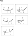
- FIG 2 shows examples a) to e) for determining losses in various stationary operating states of an asynchronous machine. Shown are a curve 14 with a calculated power loss, in particular the total loss, and a curve 15 with a difference between measured active power minus measured mechanical power.
- the curve 14 each has a minimum 16 which is identified by a rhombus.
- the curve 15 has a minimum 17 which is identified by a square. Dependence on the flow is shown in each case. It turns out that the minimum of curve 15 is always close to the minimum of curve 14. In order to optimize the asynchronous machine, a flux is thus selected in which the calculated loss (the calculated power loss) is minimal.
- the representation after 3 shows an asynchronous machine 1 which can be fed by a power converter 3 via a power cable 2 .
- the power converter 2 has a power converter control 30 .
- a model 5 is integrated into this.
- This model 5 relates, for example, to a machine model (engine model) and/or a temperature model for the machine.
- the temperatures of the individual motor masses can be measured. The temperatures are a kind of filtered losses. The colder an engine is in a given operating state, the more energy-optimal it is. A kind of temperature monitoring of the individual motor components with subordinate energy optimization is also conceivable.
- the machine is then optimized via an optimization device 29 in which a selection device 8 is integrated.
- a selection device 8 for example, an optimization type can be set and/or an optimal flow can be set (selected).
- the optimization relates in particular to an optimization of the efficiency. For this purpose, a curve is laid through these values, in particular from calculated values for machine losses with differently selected magnetic flux values, and the value for the flux is selected at which the mathematically generated curve has a minimum.
- An activation device 31 is provided for activating the optimization.
- the optimal operating point of the asynchronous machine is where the losses calculated by the thermal motor model are lowest.
- a search function can be realized for the flow to be set.
- a change in the amount of flux in an assumed direction e.g. increase in flux or reduction in flux
- the flux magnitude setpoint is then changed accordingly.
- the calculation is based on the specified load condition so that the speed and torque are fixed. In addition, there is the assumed flow rate.
- the amount of flux determines the I_sd through the saturation characteristic.
- the I_sq can be calculated from the amount of flux and torque.
- the slip results from the rotor resistance, the cross current and the amount of flux. This also results in the stator frequency. This means that all variables for the thermal motor model are known and the motor losses can be clearly calculated.
- the calculated optimal flow is limited, for example, between 50% and 120%.
- the calculated optimal flux can be taken into account, for example, fully, not at all, or on a sliding basis. For example, it is possible to switch between a function for efficiency optimization and loss optimization, with the respective optimization having full, partial or no effect, or a smooth transition between the optimization variants.
- FIGs 4 , 5 and 6 show graphs for measured values for an asynchronous machine.
- FIG 4 shows measured values for speed, current and motor temperature.
- 5 shows measured values for the flow and a calculated power loss. 6 shows a comparison of different optimizations of the asynchronous machine.
- the temperature of the stator winding was also recorded during the measurement.
- This method reduces the flow, especially with small loads. In the overload range it leaves the flux unchanged.
- the method I d I q only considers the ohmic losses, so that the optimal operating point cannot be reached.
- the representation after FIG 4 shows the motor temperature (stator winding temperature) 18, the actual speed value 19 (unsmoothed) and the amount of the actual current value 19 (smoothed) over time 21.
- the flux magnitude is not optimized (the first measurement in each case), the flux magnitude reaches the expected value of 100% as long as no field weakening takes place.
- the "efficiency optimization" (the second measurement in each case) only works by reducing the flow and only at very low loads. The process of loss optimization is almost always effective in the example: with small loads with flux reduction, with higher loads with flux increase. The total power loss is almost always reduced. If the asynchronous machine is operated in the range of the rated point, the potential for optimization is reduced if the machine is designed approximately correctly.
- a calculated power loss for the stator 22 Also shown are a calculated power loss for the stator 22, a calculated power loss for the stator winding 23, the actual flux value 24 and a calculated power loss for the rotor 25.
- the graphs shown in the figures show that the efficiency calculated from the measured variables is different for the different load states and the different optimizations. Improvements can be achieved in particular at lower speeds or in the partial load range.
Landscapes
- Engineering & Computer Science (AREA)
- Power Engineering (AREA)
- Control Of Ac Motors In General (AREA)
Description
Die Erfindung betrifft eine Asynchronmaschine. Asynchronmaschinen können in einem Betriebspunkt oder in verschiedenen Betriebspunkten betrieben werden. Hierfür sind verschiedene Steuerungen bzw. Regelungen vorsehbar.The invention relates to an asynchronous machine. Asynchronous machines can be operated at one operating point or at different operating points. Various controls or regulations can be provided for this.
Für die Steuerung und/oder Regelung der Asynchronmaschine sind verschiedenste Konzepte bekannt.A wide variety of concepts are known for controlling and/or regulating the asynchronous machine.
Die
Aus der
Auch aus der
Aus der
Aus der
Bei Asynchronmaschinen wird zunehmend gefordert, diese energieeffizient zu betreiben. Eine Aufgabe der Erfindung ist es die Regelung und/oder Steuerung einer Asynchronmaschine zu verbessern. Dadurch ist es möglich die Asynchronmaschine effizienter zu betreiben.In the case of asynchronous machines, there is an increasing demand for them to be operated in an energy-efficient manner. An object of the invention is to improve the regulation and/or control of an asynchronous machine. This makes it possible to operate the asynchronous machine more efficiently.
Eine Lösung der Aufgabe ergibt sich nach einem Verfahren zur Ermittlung eines Flusses einer Asynchronmaschine nach Anspruch 1 bzw. gemäß einer Vorrichtung zur Bestimmung eines Flusses einer Asynchronmaschine, nach Anspruch 8. Asynchronmaschinen können im Spannungsstellbereich mit dem Nennfluss der Asynchronmaschine betrieben werden. Ein vorgegebener Lastzustand (festes Drehmoment und feste Drehzahl) kann aber auch mit einem anderen Flussbetrag erreicht werden. Der Flussbetrag ist in einem Bereich von etwa 50% bis 120% (je nach Lastzustand) frei wählbar. Dieser Freiheitsgrad kann zur Optimierungen, z.B. zur Wirkungsgradoptimierung eingesetzt werden.A solution to the problem results from a method for determining a flow of an asynchronous machine according to
Bei einem Verfahren zur Ermittlung eines Flusses einer Asynchronmaschine, wird der Fluss in Abhängigkeit eines Verlustes der Asynchronmaschine eingestellt. So kann der Wirkungsgrad der Asynchronmaschine durch eine Verkleinerung/Minimierung des Verlustes der Asynchronmaschine verbessert/optimiert werden (Verlustoptimierung).In a method for determining a flux of an asynchronous machine, the flux is adjusted as a function of a loss in the asynchronous machine. The efficiency of the asynchronous machine can thus be improved/optimized by reducing/minimizing the loss of the asynchronous machine (loss optimization).
In einer Ausgestaltung des Verfahrens, welche nicht Teil der Erfindung ist, wird dabei eine nichtlineare Sättigungskennlinie verwendet. Mittels der nichtlinearen Sättigungskennlinie lässt der Verlust genauer berechnen. Bei einer Asynchronmaschine gibt es verschiedene Bereiche, welche für den Verlust von Relevanz sein können. Diese Bereiche sind beispielsweise ohmsche Verluste im Ständer, ohmsche Verluste im Rotor, Eisenverluste, mechanische Verluste, etc. Zu den mechanischen Verlusten zählen Reibungsverluste wie Verluste in einem Lager. Auch Ventilationsverluste, welche bei einer Kühlung auftreten können, tragen zu den Gesamtverlusten bei. Bei eigenbelüfteten Maschinen ändert sich der Leistungsbedarf proportional zur dritten Potenz der Drehzahl. Strömungsverluste, die durch Luftwirbel zwischen Ständer und Rotor auftreten, können auch Berücksichtigung finden, sind aber in der Regel klein und damit ggf. auch vernachlässigbar.In one embodiment of the method, which is not part of the invention, a non-linear saturation characteristic is used. The loss can be calculated more precisely using the non-linear saturation characteristic. With an asynchronous machine, there are various areas that can be relevant to the loss. These areas are, for example, ohmic losses in the stator, ohmic losses in the rotor, iron losses, mechanical losses, etc. Mechanical losses include friction losses such as losses in a bearing. Ventilation losses, which can occur during cooling, also contribute to the total losses. In the case of self-ventilated machines, the power requirement changes in proportion to the third power of the speed. Flow losses caused by air vortices between stand and Rotor that occur can also be taken into account, but are usually small and therefore possibly also negligible.
Bei einer Bestimmung der Verlustleistung kann man zwischen einer direkten und einer indirekten Bestimmung der Verlustleistung unterscheiden. Bei der direkten Bestimmung werden die Verlustarten durch gezielte Messungen erfasst. Bei einer indirekten Messung werden Eingangs- und Ausgangsleistungen definiert. Die Verlustleistung wird als Unterschied definiert. Da es sich bei dieser Differenzbildung um zwei etwa gleich große Größen handelt, sind die Einzelleistungen Pin und Pout recht genau zu bestimmen, um die Verlustleistung Pv in einer genügenden Genauigkeit zu erhalten: Pv =Pin-Pout. Obwohl die mechanischen Verluste zum Teil sehr relevant sind, spielen sie bei der Energieoptimierung durch den Umrichter dennoch keine Rolle, weil ein durch Drehzahl und Drehmoment festgelegter Arbeitspunkt keinen freien Spielraum lässt. Die Reduzierung dieser Verlustart ist durch konstruktive Maßnahmen z.B. Fremdbelüftung möglich.When determining the power loss, a distinction can be made between a direct and an indirect determination of the power loss. In the case of direct determination, the types of loss are recorded through targeted measurements. With an indirect measurement, input and output powers are defined. The power dissipation is defined as the difference. Since this subtraction involves two quantities of approximately the same size, the individual powers P in and P out must be determined very precisely in order to obtain the power loss P v with sufficient accuracy: P v = Pi n -P out. Although some of the mechanical losses are very relevant, they do not play a role in the energy optimization by the converter because an operating point defined by speed and torque leaves no room for maneuver. This type of loss can be reduced by design measures such as external ventilation.
Alle Arten von Verlusten, die nicht einzeln berücksichtigt sind, werden als "Zusatzverluste" beschrieben, wie z.B. in DIN EN 60034-2-1 definiert.All types of losses that are not considered individually are described as "additional losses" as defined, for example, in DIN EN 60034-2-1.
In einer Ausgestaltung des Verfahrens wird der Verlust mittels eines Modells ermittelt. Das Modell berücksichtigt insbesondere Verluste im Motor, also in der elektrischen Maschine. Dies sind insbesondere ohmsche Verluste, ohmsche Verluste im Ständer der elektrischen Maschine und/oder ohmsche Verluste im Rotor der elektrischen Maschine. Auch Eisenverluste sind Verluste der elektrischen Maschine, welche im Modell berücksichtigt werden können. Da die Rotorfrequenz im stationären Zustand vergleichsweise gering ist, können die Grundschwingungseisenverluste im Rotor gegenüber denen im Ständer praktisch vernachlässigt werden. Im Umrichterbetrieb sind die Eisenverluste wegen des signifikanten harmonischen Anteils (Strom, Spannung) höher als im Netzbetrieb. In einem Ersatzschaltbild für die elektrische Maschine kann z.B. der Eisenverlust durch einen Widerstand parallel zur Hauptinduktivität berücksichtigt werden. Im Modell können auch Hystereseverluste mit berücksichtigt werden. Die Hystereseverluste können die Eisenverluste im Spannungsstellbereich dominieren. Sie ergeben sich wie folgt: ![]()
![]()
Im Modell können auch Wirbelstromverluste mit berücksichtigt werden. Die Wirbelstromverluste können die Eisenverluste im Feldschwächenbereich dominieren. Sie ergeben sich wie folgt: ![]()
![]()
In einer Ausgestaltung des Verfahrens, welche nicht Teil der Erfindung ist, ist im Modell eine nichtlineare Sättigungskennlinie berücksichtigt. Diese Kennlinie kann direkt im Modell hinterlegt sein.In one embodiment of the method, which is not part of the invention, a non-linear saturation characteristic is taken into account in the model. This characteristic can be stored directly in the model.
In einer Ausgestaltung des Verfahrens wird der Verlust mittels eines Modells ermittelt, wobei zur Verkleinerung (Minimierung) des Verlustes der Fluss entweder unter 100% reduziert wird, oder auf über 100% erhöht wird.In one embodiment of the method, the loss is determined using a model, with the flow being either reduced below 100% or increased to over 100% in order to reduce (minimize) the loss.
Asynchronmaschinen können im Spannungsstellbereich mit dem Nennfluss der Asynchronmaschine bei 100% Fluss betrieben werden. Ein vorgegebener Lastzustand (festes Drehmoment und feste Drehzahl) kann aber auch mit einem anderen Flussbetrag erreicht werden. Der Flussbetrag ist beispielsweise in einem Bereich von etwa 50% bis 120% (je nach Lastzustand) wählbar. Durch den gewählten Fluss wird der Verlust der Asynchronmaschine beeinflusst. Abhängig vom Betriebszustand der Asynchronmaschine kann eine Erhöhung des Flusses über 100% des Nennflusses zu einer Verkleinerung des Verlustes führen.Asynchronous machines can be operated in the voltage setting range with the nominal flux of the asynchronous machine at 100% flux. However, a specified load condition (fixed torque and fixed speed) can also be achieved with a different amount of flux. The amount of flux can be selected, for example, in a range from approximately 50% to 120% (depending on the load condition). The loss of the asynchronous machine is influenced by the selected flux. Depending on the operating state of the asynchronous machine, an increase in the flux above 100% of the nominal flux can lead to a reduction in the loss.
In einer Ausgestaltung des Verfahrens, welche nicht Teil der Erfindung ist, wird ein neuer einzustellender Fluss für einen minimalen Verlust nicht durch ein iteratives Herantasten an den minimalen Verlust durch iteratives Einstellen des Flusses erreicht. In einer Ausgestaltung des Verfahrens wird ein Fluss ermittelt, bei dem der Verlust ein Minimum hat und in einem Schritt dieser ermittelte Fluss eingestellt.In an embodiment of the method, which is not part of the invention, a new flow to be set for a minimum loss is not achieved by iteratively approaching the minimum loss by iteratively setting the flow. In an embodiment of the method, a flow is determined in which the loss has a minimum and this determined flow is set in one step.
In einer Ausgestaltung des Verfahrens weist das Modell der elektrischen Maschine ein thermisches Modell auf. Zumindest ein Teil der Verluste in der Asynchronmaschine ist mit dem thermischen Motormodell berechenbar. Das thermische Modell kann auch für den Motorschutz und eine Widerstandsadaption verwendet werden. Die Berechnung des thermischen Modells wird in einer Ausgestaltung (auch) für die Wirkungsgradoptimierung eingesetzt.In one configuration of the method, the model of the electrical machine has a thermal model. At least some of the losses in the asynchronous machine can be calculated using the thermal motor model. The thermal model can also be used for motor protection and resistor adaptation. In one embodiment, the calculation of the thermal model is (also) used for efficiency optimization.
In einer Ausgestaltung des Verfahrens, welche nicht Teil der Erfindung ist, werden die ohmschen Verluste berücksichtigt. Die ohmschen Verluste sind proportional zu dem Quadrat des Stromes und linear abhängig von dem Widerstand des Leiters. Dieser Widerstandswert ist temperaturabhängig und diese Abhängigkeit kann im Regelfall nicht vernachlässigt werden: ![]()
![]()
Bei Kupfer ist der Wert ![]()
![]()
![]()
![]()
Es gilt die Faustregel, dass bei 100 K Temperaturerhöhung etwa 40% Widerstandserhöhung zu erwarten ist. Bei den Grundschwingungsfrequenzen im stationären Zustand spielt die Stromverdrängung oft keine besonders wichtige Rolle. Beim Umrichterbetrieb sind die Oberschwingungen in den Strömen und die dadurch verursachten ohmschen Verluste wegen der reduzierten Eindringtiefe aber nicht mehr zu vernachlässigen. Die Ersatzwiderstände für die n-ten Harmonischen Rn können z.B. wiefolgt modelliert werden, wobei n die Ordnungszahl der entsprechenden Harmonischen und f die Frequenz der Harmonische (bezogen auf die Nennfrequenz) ist: ![]()
![]()
Die Parameter kn können mit der Finite-Elemente-Methode gewonnen werden. Die ohmschen Verluste im Ständer errechnen sich gemäß: ![]()
![]()
Bei der Messung von Rs (Ständerwiderstand) ist darauf zu achten, dass der eventuell mitgemessene Kabelwiderstand zwar bei der Regelung zu berücksichtigen ist, sich aber nicht so temperaturabhängig ändert, wie der Widerstand der Ständerwicklung. Bei den ohmschen Verlusten im Ständer ist anzumerken, dass dazu sowohl die Längskomponente id des Stroms als auch die entsprechende Querkomponente iq etwas beitragen. Ohmsche Verluste im Rotor (Läufer) sind gemäß der Gleichung ![]()
![]()
In einer Ausgestaltung des Verfahrens wird der Fluss (magnetische Fluss der elektrischen Maschine) bei einem minimalen Verlust eingestellt. Der Fluss wird also so gewählt, dass der Verlust minimal ist. Hierzu wird ein Modell der elektrischen Maschine verwendet, mit dem eine Berechnung des Verlustes möglich ist. Dies betrifft insbesondere nur einen Teil des Gesamtverlustes der elektrischen Maschine.In one configuration of the method, the flux (magnetic flux of the electrical machine) is set with a minimum loss. So the flow is chosen so that the loss is minimal. For this purpose, a model of the electrical machine is used, with which a calculation of the loss is possible. In particular, this relates to only part of the total loss of the electrical machine.
In einer Ausgestaltung des Verfahrens, welche nicht Teil der Erfindung ist, wird ein Längsstrom Id der elektrischen Maschine ungleich einem Querstrom Iq der elektrischen Maschine eingestellt. Dies rührt aus der Erkenntniss, dass mit einer Bedingung Iq=Id in der Regel noch nicht der optimalste Betriebspunkt der elektrischen Maschine erzielbar ist.In one embodiment of the method, which is not part of the invention, a longitudinal current I d of the electrical machine is set to be unequal to a transverse current I q of the electrical machine. This stems from the knowledge that the optimum operating point of the electrical machine cannot generally be achieved with a condition I q =I d .
In einer Ausgestaltung des Verfahrens wird der Wirkungsgrad der elektrischen Maschine optimiert. Zur Optimierung wird mittels eines Modells ein Verlust, z.B. ein ohmscher Verlust, welcher von der Temperatur abhängig ist, der elektrischen Maschine in einem Modell errechnet. Abhängig vom im Modell gewählten Fluss ändert sich der errechnete Verlust. An der elektrischen Maschine wird der Fluss eingestellt, welcher im Modell den geringsten Verlust ergab.In one configuration of the method, the efficiency of the electrical machine is optimized. For optimization, a loss, e.g. an ohmic loss, which depends on the temperature, of the electrical machine is calculated in a model using a model. The calculated loss changes depending on the flow selected in the model. The flux that resulted in the lowest loss in the model is set on the electrical machine.
In einer Ausgestaltung des Verfahrens, welche nicht Teil der Erfindung ist, unterscheidet sich der Strombetrag beim eingestellten Fluss vom minimalen Strombetrag. Ergibt sich eine derartige Situation wird klar, dass ein optimaler effizienter Betrieb der elektrischen Maschine auch dann erreicht werden kann, wenn ein Fluss gewählt wird, bei dem der Strombetrag nicht minimal ist.In an embodiment of the method, which is not part of the invention, the amount of current at the set flow differs from the minimum amount of current. If such a situation arises, it becomes clear that optimal efficient operation of the electrical machine can also be achieved if a flux is selected in which the amount of current is not minimal.
In einer Ausgestaltung des Verfahrens, welche nicht Teil der Erfindung ist, kann die Einstellung des Flusses lastunabhängig erfolgen. Aus einem vorgegebenen Lastzustand (gegeben durch Drehmoment und/oder Drehzahl) und dem bekannten Flussbetrag wird in einer Ausgestaltung des Verfahrens, welche nicht Teil der Erfindung ist, die aktuelle Verlustleitung berechnet. Dann wird für den gleichen Lastzustand bei einem angenommen etwas (z.B. etwa 5%) kleineren und einem größeren Flussbetrag die Verlustleistung berechnet. Die Differenzen zwischen den Flussbeträgen, welche zur Berechnung der Verlustleistung herangezogen werden, können sich auch in einem Band von 1% und 10% bewegen, bzw. aus diesem ausgewählt werden. Der Prozentsatz kann auch abhängig vom Betriebszustand der elektrischen Maschine gewählt werden. Aus den drei Verlustwerten (bei kleinerem Fluss, bei aktuellem Fluss, bei größerem Fluss) wird insbesondere durch parabolische Annäherung eine minimale Verlustleistung berechnet. Der zur minimalen Verlustleitung gehörige Fluss wird als optimaler Fluss eingestellt. Das Verfahren kann weitere Iterationsschritte aufweisen.In one embodiment of the method, which is not part of the invention, the flux can be adjusted independently of the load. In one embodiment of the method, which is not part of the invention, the current power loss is calculated from a predetermined load state (given by torque and/or speed) and the known amount of flux. Then the power loss is calculated for the same load condition with an assumed slightly (e.g. about 5%) smaller and a larger flux amount. The differences between the flux amounts, which are used to calculate the power loss, can also be in a range of 1% and 10%, or can be selected from this range. The percentage can also be selected depending on the operating state of the electrical machine. A minimum power loss is calculated from the three loss values (at a smaller flow, at the current flow, at a larger flow), in particular by parabolic approximation. The flow associated with the minimum power dissipation is set as the optimum flow. The method can have further iteration steps.
In einer Ausgestaltung des Verfahrens wird eine Änderung des Verlustes abhängig von einer Änderung des Flusses errechnet, wobei der Fluss in Abhängigkeit des errechneten Verlustes eingestellt wird. Dies kann als schnelles und stabiles Verfahren realisiert werden. Der Fluss wird insbesondere so eingestellt, dass der Wirkungsgrad den messtechnisch maximal erreichbaren Wert erreicht. Das Verfahren kann ohne eine Iteration durchgeführt werden. Wegen der direkten Berechnung (ohne Iteration) ist das Verfahren schneller und zuverlässiger als ein iteratives Verfahren. Eine Berücksichtigung des Eisenverlustes (welcher immerhin 15 bis 25% des Nennverlustes ausmachen kann und bei einem Verfahren welche die Bedingung Id=Iq berücksichtigt komplett vernachlässigt wird) ermöglicht die verbesserte, insbesondere maximale, Wirkungsgradoptimierung.In one embodiment of the method, a change in the calculated as a function of a change in flow, where the flow is adjusted depending on the calculated loss. This can be realized as a fast and stable method. In particular, the flow is set in such a way that the efficiency reaches the maximum value that can be reached by measurement. The method can be performed without an iteration. Because of the direct calculation (without iteration), the method is faster and more reliable than an iterative method. Taking into account the iron loss (which can still account for 15 to 25% of the nominal loss and is completely neglected in a method that takes the condition I d =I q into account) enables improved, in particular maximum, efficiency optimization.
Das Verfahren ist nach den beschriebenen Ausgestaltungen insbesondere direkt, schnell und zuverlässig. Insbesondere werden dafür keine neuen Motorparameter benötigt, die bereits bekannten und vorhandenen Parameter sind ausreichend. Eine bislang vielleicht schon vorhandene Motordatenbank muss nicht erweitert werden. Das beschriebene Verfahren zur Ermittlung des Flusses der elektrischen Maschine für deren Optimierung, benötigt wenig Rechenzeit ist kostengünstig realisierbar.According to the configurations described, the method is in particular direct, fast and reliable. In particular, no new motor parameters are required for this, the already known and existing parameters are sufficient. A previously existing motor database does not need to be expanded. The method described for determining the flow of the electrical machine for its optimization requires little computing time and can be implemented cost-effectively.
In einer Ausgestaltung des Verfahrens wird der Verlust bei einem aktuellen Fluss im Betrieb der Asynchronmaschine, bei einem dazu reduzierten Fluss und bei einem ebenso dazu erhöhten Fluss berechnet, wobei mittels der errechneten Verluste das Minimum einer Kurve ermittelt wird, wobei der Fluss beim minimalen Verlust eingestellt wird. Bei einem aktuellen Fluss während des Betriebes der Asynchronmaschine wird also mittels des Modells (zur/für die Asynchronmaschine) ein aktueller Verlust errechnet. Ferner wird mittels des Modells ein Verlust errechnet, der sich einstellen würde, wenn der Fluss reduziert werden würde. Ferner wird mittels des Modells ein Verlust errechnet, der sich einstellen würde, wenn der Fluss erhöht werden würde. Die Reduzierung bzw. die Erniedrigung betrifft dabei eine angenommene Änderung zum aktuellen Fluss. Zum aktuellen Fluss, zum angenommenen reduzierten Fluss und zum angenommenen erhöhten Fluss werden die Verluste errechnet. Aus diesen Werten zu den Verlusten lässt sich eine Funktion bilden, insbesondere eine Polygonfunktion oder eine Parabelfunktion. Zu dieser gebildeten Funktion, welche den Verlust wiederspiegelt und vom Fluss abhängt, lässt sich ein Minimum finden, also ein Wert, bei dem der Verlust minimiert ist und/oder minimal ist. Der Wert des Flusses, bei dem der Verlust der Asynchronmaschine minimiert und/oder minimal ist, kann dann eingestellt bzw. angefahren werden. So ist die Einstellung des Flusses in einem Schritt möglich. Eine iterative Vorgehensweise zur Einstellung des besten Flusses ist damit nicht mehr notwendig. Die angenommenen Änderungen zum aktuellen Fluss, also die Werte des angenommenen erhöhten Flusses und des angenommenen reduzierten Flusses zur Berechnung zur Berechnung des Verlustes bzw. der Verlustfunktion sind insbesondere so zu wählen, dass diese zur Ausbildung einer Parabelfunktion bzw. einer Polygonfunktion ausreichen.In one embodiment of the method, the loss is calculated for a current flow during operation of the asynchronous machine, for a reduced flow and for a flow that is also increased, the minimum of a curve being determined using the calculated losses, with the flow being set at the minimum loss will. In the case of a current flow during operation of the asynchronous machine, a current loss is calculated using the model (to/for the asynchronous machine). The model is also used to calculate a loss that would occur if the flow were reduced. Furthermore, the model is used to calculate a loss that would occur if the flow were to be increased. The reduction or lowering relates to an assumed change to the current flow. The losses are calculated for the current flow, the assumed reduced flow and the assumed increased flow. A function can be formed from these values for the losses, in particular a polygon function or a parabolic function. A minimum can be found for this formed function, which reflects the loss and depends on the flow, i.e. a value at which the loss is minimized and/or minimal. The flux value at which the loss of the asynchronous machine is minimized and/or minimal can then be set or approached. This allows the flow to be set in one step. An iterative procedure for setting the best flow is therefore no longer necessary. The assumed changes to the current flow, ie the values of the assumed increased flow and the assumed reduced flow for the calculation of the loss or the loss function, are to be selected in particular in such a way that they are sufficient to form a parabolic function or a polygon function.
Eine Lösung der Aufgabe gelingt auch mittels einer Vorrichtung. Die Vorrichtung zur Bestimmung eines Flusses einer Asynchronmaschine weist ein Modell zur Berechnung eines Verlustes der Asynchronmaschine abhängig vom Fluss der Asynchronmaschine auf und eine Auswahleinrichtung zur Auswahl eines Flusses abhängig vom Verlust. Es ist der Fluss auszuwählen bei dem der Verlust im Vergleich am kleinsten ist.The task can also be solved by means of a device. The device for determining a flow of an asynchronous machine has a model for calculating a loss of the asynchronous machine depending on the flow of the asynchronous machine and a selection device for selecting a flow depending on the loss. The flow is to be selected for which the loss is the smallest in comparison.
In einer Ausgestaltung der Vorrichtung weist diese eine Aktivierungseinrichtung für die Vorrichtung auf. Damit ist eine Aktivierung abhängig von der Lastdynamik der Asynchronmaschine möglich.In one configuration of the device, it has an activation device for the device. This enables activation depending on the load dynamics of the asynchronous machine.
In einer Ausgestaltung der Vorrichtung ist diese in einen Stromrichter integriert. So können Motordaten, die in dem Stromrichter gespeichert sind, mit verwendet werden. So kann auch die Rechenleistung des Stromrichters, welche zur Regelung der elektrischen Maschine vorhanden ist, mit genutzt werden.In one configuration of the device, it is integrated in a power converter. In this way, motor data stored in the power converter can also be used. In this way, the computing power of the power converter, which is available for controlling the electrical machine, can also be used.
Mittels der Vorrichtung kann eines der beschriebenen Verfahren durchgeführt werden, bzw. kann bei einem der Verfahren die Vorrichtung verwendet werden.One of the methods described can be carried out by means of the device, or the device can be used in one of the methods.
In einer Ausgestaltung, welche nicht Teil der Erfindung ist, werden bei einem energieoptimalen Betrieb der Asynchronmaschine Sättigungen und Eisenverluste bei der Berechnung des Sollwertes für den Fluss berücksichtigt.In one embodiment, which is not part of the invention, saturations and core losses are taken into account when calculating the setpoint value for the flux in the case of energy-optimal operation of the asynchronous machine.
Die Erfindung wird nachfolgend auf der Basis von Ausführungsbeispielen unter Bezugnahme auf die beiliegende Zeichnungen exemplarisch weiter erläutert, wobei gleichartige Elemente die gleichen Bezugszeichen aufweisen. Dabei zeigt:
- FIG 1
- eine Abhängigkeit des Wirkungsgrades einer Asynchronmaschine von einer Vorgabe des Flusses;
- FIG 2
- Beispiele für eine Verlustermittlung;
- FIG 3
- eine Asynchronmaschine mit einem Stromrichter;
- FIG 4
- Messwerte für Drehzahl, Strom und Motortemperatur;
- FIG 5
- Messwerte für den Fluss und eine errechnete Verlustleistung und
- FIG 6
- einen Vergleich verschiedener Optimierungen der Asynchronmaschine.
- FIG 1
- a dependency of the efficiency of an asynchronous machine on a specification of the flux;
- FIG 2
- Examples of loss determination;
- 3
- an asynchronous machine with a power converter;
- FIG 4
- Speed, current and motor temperature readings;
- 5
- Measured values for the flow and a calculated power loss and
- 6
- a comparison of different optimizations of the asynchronous machine.
Die Darstellung nach
Die Darstellung nach
Der Flussbetrag legt durch die Sättigungskennlinie den Wert für Id soll (i_sd) fest. Der Wert Iq soll (i_sq) kann aus Flussbetrag und Drehmoment berechnet werden. Der Schlupf ergibt sich aus dem Rotorwiderstand, dem Querstrom und dem Flussbetrag. Damit ergibt sich auch die Ständerfrequenz. Damit sind alle Größen für ein thermisches Motormodell bekannt und die Motorverluste können eindeutig berechnet werden. Damit können sich folgende Gleichungen ergeben:
 i_sq = k_t * Psi * m Querstrom
 i_sd = f(Psi) Erregerstrom (Sättigungskennlinie
                        (bei Inbetriebnahme gemessen)
 is^2 = i_sd^2 + i_sq^2 Ständerstrom
 f_r = * R_r * i_sq / Psi / 2 / pi Rotorfrequenz
 f_s = Zp * n + f_r Statorfrequenz
     Mit:
 i_sq = k_t * Psi * m cross current
 i_sd = f(Psi) excitation current (saturation characteristic
                        (measured at start-up)
 is^2 = i_sd^2 + i_sq^2 stator current
 f_r = * R_r * i_sq / Psi / 2 / pi rotor frequency
 f_s = Zp * n + f_r stator frequency
     With:
Die Darstellung nach
Über eine Optimierungseinrichtung 29, in welche eine Auswahleinrichtung 8 integriert ist, dann eine Optimierung der Maschine erfolgen. Mit der Auswahleinrichtung 8 kann beispielsweise eine Optimierungsart eingestellt werden und/oder ein optimaler Fluss eingestellt (ausgewählt) werden. Die Optimierung betrifft insbesondere eine Optimierung des Wirkungsgrades. Dafür wird insbesondere aus berechneten Werten für Maschinenverluste bei unterschiedlich gewählten magnetische Flusswerten eine Kurve durch diese Werte gelegt und der Wert für den Fluss ausgewählt, bei welchem die mathematisch erzeugte Kurve ein Minimum aufweist. Zur Aktivierung der Optimierung ist eine Aktivierungseinrichtung 31 vorgesehen.The machine is then optimized via an
Der optimale Betriebspunkt der Asynchronmaschine, bzw. ein diesem nahekommender Betriebspunkt, befindet sich dort, wo die vom thermischen Motormodell berechneten Verluste am kleinsten sind. Aufbauend auf dieser Tatsache kann eine Suchfunktion für den einzustellenden Fluss realisiert werden. In einem stationären Zustand der Asynchronmaschine kann vor einer realen Änderung des Flusses, also vor einer Änderung des Sollwertes für den Fluss, ausgerechnet werden, ob sich eine Flussbetragsänderung in eine angenommene Richtung (z.B. Erhöhung des Flusses bzw. Reduzierung des Flusses) positiv oder negativ auf den Wirkungsgrad auswirken würde. Der Flussbetragssollwert wird dann entsprechend geändert.The optimal operating point of the asynchronous machine, or an operating point that comes close to it, is where the losses calculated by the thermal motor model are lowest. Building on this fact, a search function can be realized for the flow to be set. In a stationary state of the asynchronous machine, before a real change in the flux, i.e. before a change in the setpoint for the flux, it can be calculated whether a change in the amount of flux in an assumed direction (e.g. increase in flux or reduction in flux) will be positive or negative would affect the efficiency. The flux magnitude setpoint is then changed accordingly.
Die Berechnung geht von dem vorgegebenen Lastzustand aus, damit die Drehzahl und das Drehmoment festgelegt sind. Dazu kommt noch der angenommene Flussbetrag. Der Flussbetrag legt durch die Sättigungskennlinie den I_sd fest. Der I_sq kann aus Flussbetrag und Drehmoment berechnet werden. Der Schlupf ergibt sich aus dem Rotorwiderstand, dem Querstrom und dem Flussbetrag. Damit ergibt sich auch die Ständerfrequenz. Damit sind alle Größen für das thermische Motormodell bekannt und die Motorverluste können eindeutig berechnet werden.The calculation is based on the specified load condition so that the speed and torque are fixed. In addition, there is the assumed flow rate. The amount of flux determines the I_sd through the saturation characteristic. The I_sq can be calculated from the amount of flux and torque. The slip results from the rotor resistance, the cross current and the amount of flux. This also results in the stator frequency. This means that all variables for the thermal motor model are known and the motor losses can be clearly calculated.
Der berechnete optimale Fluss wird beispielsweise zwischen 50% und 120% eingegrenzt. In der Regelung des Stromrichters für die Asynchronmaschine kann der berechnete optimale Fluss beispielsweise voll, nicht oder gleitend berücksichtigt werden. So kann beispielsweise zwischen einer Funktion zur Wirkungsgradoptimierung und einer Verlustoptimierung gewechselt werden, wobei die jeweilige Optimierung voll, nicht oder teilweise wirkt, bzw. ein gleitender Übergang zwischen den Optimierungsvarianten erfolgt.The calculated optimal flow is limited, for example, between 50% and 120%. In the control of the power converter for the asynchronous machine, the calculated optimal flux can be taken into account, for example, fully, not at all, or on a sliding basis. For example, it is possible to switch between a function for efficiency optimization and loss optimization, with the respective optimization having full, partial or no effect, or a smooth transition between the optimization variants.
Die Darstellungen nach den
Für die Messwertaufnahme der
- 1. ohne Flussoptimierung
- 2. mit Wirkungsgradoptimierung (I_sd = I_sq)
- 3. mit Verlustoptimierung (der minimale Verlust ist optimal).
- 1. without flow optimization
- 2. with efficiency optimization (I_sd = I_sq)
- 3. with loss optimization (the minimum loss is optimal).
Während der Messung wurde auch die Temperatur der Ständerwicklung aufgenommen.The temperature of the stator winding was also recorded during the measurement.
Beim Punkt 2 der obigen Aufzählung erfolgt die Optimierung der Asynchronmaschine in einem Regelungsmodus (sowohl Servo als auch Vektor) beispielsweise so, dass der Erregerstrom so eingestellt wird, dass sein Betrag dem drehmomentbildenden Strom entspricht (Id=Iq Verfahren). Dieses Verfahren reduziert den Fluss insbesondere bei kleinen Belastungen. Im Überlastbereich lässt es den Fluss unverändert. Das Verfahren Id=Iq berücksichtigt nur die ohmsche Verluste, so dass der optimale Betriebspunkt nicht erreicht werden kann.In
Die Darstellung nach
In der Darstellung nach
- 1. ohne Flussoptimierung
- 2. mit Wirkungsgradoptimierung (I_sd = I_sq)
- 3. mit Verlustoptimierung (der minimale Verlust ist optimal)
- 1. without flow optimization
- 2. with efficiency optimization (I_sd = I_sq)
- 3. with loss optimization (the minimum loss is optimal)
Im Überlastzustand ergibt sich, wie ersichtlich ist, eine Übermagnetisierung der Maschine, solange nicht die Spannungsgrenze wirkt. Weiterhin ist bei bestimmten Betriebszuständen zu beobachten, dass bei Anwendung der Verlustoptimierung (Punkt 3 von oben) bei der Flussreduzierung mehr Strom fließt als bei den anderen beiden Verfahren (Punkt 1 und 2 von oben). Die Gesamtverluste werden trotzdem reduziert. Durch die Flussreduzierung ist die Verringerung der Eisenverluste stärker als die Gesamterhöhung der Kupferverluste im Ständer und Rotor.As can be seen, in the overload state the machine is overmagnetized as long as the voltage limit is not effective. Furthermore, it can be observed in certain operating states that when using loss optimization (
In der Darstellung nach
- 1. ohne Flussoptimierung in einer ersten
Phase 26 - 2. mit Wirkungsgradoptimierung (I_sd = I_sq) in einer zweiten
Phase 27 - 3. mit Verlustoptimierung (der minimale Verlust ist optimal) in einer dritten
Phase 28.
- 1. without flow optimization in a
first phase 26 - 2. with efficiency optimization (I_sd = I_sq) in a
second phase 27 - 3. with loss optimization (the minimum loss is optimal) in a
third phase 28.
Dargestellt sind ferner eine berechnete Verlustleistung für den Stator 22, eine berechnete Verlustleistung für die Statorwicklung 23, der Flussistwert 24 und eine berechnete Verlustleistung für den Rotor 25.Also shown are a calculated power loss for the
Die in den Figuren gezeigten Graphen lassen erkennen, dass der aus den gemessenen Größen berechnete Wirkungsgrad bei den unterschiedlichen Belastungszuständen und den unterschiedlichen Optimierungen unterschiedlich ist. Verbesserungen können insbesondere bei kleineren Drehzahlen bzw. im Teillastbereich erreicht werden.The graphs shown in the figures show that the efficiency calculated from the measured variables is different for the different load states and the different optimizations. Improvements can be achieved in particular at lower speeds or in the partial load range.
Claims (11)
- Method for determining a flux (4) of an asynchronous machine (1), wherein the flux (4) is set as a function of a loss (7) of the asynchronous machine (1), wherein the flux (4) is set as a function of load, characterised in that a specified load state of the asynchronous machine (1) is based on a fixed torque and a fixed speed.
- Method according to claim 1, wherein the loss (7) is determined by means of a model (5), wherein the flux (4) is either reduced below 100% or is increased above 100%.
- Method according to claim 2, wherein the model (5) has a thermal model (5).
- Method according to one of claims 1 to 3, wherein the flux (4) with a minimal loss is set.
- Method according to one of claims 1 to 4, wherein the efficiency (6) is optimised.
- Method according to one of claims 1 to 5, wherein a change in the loss (7) is calculated as a function of a change in the flux (4) and the flux (4) is set as a function of the calculated loss.
- Method according to one of claims 1 to 6, wherein the loss (7) is calculated in the case of a current flux (4), in the case of a reduced flux and in the case of an increased flux, wherein the minimum of a curve or of a function is determined by means of the calculated losses, wherein the flux (4) with minimal loss is set.
- Device for determining a flux (4) of an asynchronous machine (1), characterised in that the device is provided for carrying out the method according to one of claims 1 to 7, having a model (5) for calculating a loss (7) of the asynchronous machine (1) as a function of the flux of the asynchronous machine and having a selection facility (8) for the selection of a flux (7) as a function of the loss.
- Device according to claim 8, having an activation facility (31) for the device, as a function of the load dynamics of the asynchronous machine (1).
- Device according to claim 8 or 9, which is integrated in a rectifier.
- Device according to one of claims 8 to 10, wherein the efficiency of the asynchronous machine (1) can be optimised by means of the selection facility for the selection of a flux (4) .
Applications Claiming Priority (2)
| Application Number | Priority Date | Filing Date | Title |
|---|---|---|---|
| EP17194133.9A EP3462600A1 (en) | 2017-09-29 | 2017-09-29 | Energy efficient asynchronous machine |
| PCT/EP2018/075508 WO2019063419A1 (en) | 2017-09-29 | 2018-09-20 | Energy-efficient asynchronous machine |
Publications (2)
| Publication Number | Publication Date |
|---|---|
| EP3652854A1 EP3652854A1 (en) | 2020-05-20 |
| EP3652854B1 true EP3652854B1 (en) | 2022-03-23 |
Family
ID=59997277
Family Applications (2)
| Application Number | Title | Priority Date | Filing Date |
|---|---|---|---|
| EP17194133.9A Withdrawn EP3462600A1 (en) | 2017-09-29 | 2017-09-29 | Energy efficient asynchronous machine |
| EP18785260.3A Active EP3652854B1 (en) | 2017-09-29 | 2018-09-20 | Energy efficient asynchronous machine |
Family Applications Before (1)
| Application Number | Title | Priority Date | Filing Date |
|---|---|---|---|
| EP17194133.9A Withdrawn EP3462600A1 (en) | 2017-09-29 | 2017-09-29 | Energy efficient asynchronous machine |
Country Status (4)
| Country | Link |
|---|---|
| US (1) | US11283383B2 (en) |
| EP (2) | EP3462600A1 (en) |
| CN (1) | CN111164880B (en) |
| WO (1) | WO2019063419A1 (en) |
Families Citing this family (1)
| Publication number | Priority date | Publication date | Assignee | Title |
|---|---|---|---|---|
| WO2023156159A1 (en) * | 2022-02-16 | 2023-08-24 | Sew-Eurodrive Gmbh & Co. Kg | Drive system |
Citations (9)
| Publication number | Priority date | Publication date | Assignee | Title |
|---|---|---|---|---|
| DE102006045044B3 (en) | 2006-09-25 | 2008-06-12 | Vdo Automotive Ag | Method and controller for controlling a continuously variable electric transmission |
| EP2131488A1 (en) | 2007-03-08 | 2009-12-09 | Mitsubishi Electric Corporation | Controller of electric vehicle |
| DE102009025390A1 (en) | 2008-07-09 | 2010-01-14 | Sew-Eurodrive Gmbh & Co. Kg | Converter-fed electric motor i.e. asynchronous motor, controlling method, involves determining temperature value of short-circuit cage, and determining estimated reactive power by model values determined in rotor flow-guided machine model |
| WO2012037983A1 (en) | 2010-09-24 | 2012-03-29 | Lenze Drives Gmbh | Method for controlling an asynchronous machine having a converter in a manner that is optimal for (copper) loss |
| DE102011118480A1 (en) | 2011-11-14 | 2013-05-16 | Sew-Eurodrive Gmbh & Co. Kg | System for operating an inverter-fed electric induction machine |
| DE102013209347A1 (en) | 2013-05-21 | 2014-11-27 | Robert Bosch Gmbh | Simulating a field-oriented slip frequency of an asynchronous machine |
| EP2811644A1 (en) | 2012-01-30 | 2014-12-10 | Mitsubishi Electric Corporation | Motor control device |
| DE102014213985A1 (en) | 2014-07-17 | 2016-01-21 | Magna powertrain gmbh & co kg | A vehicle and devices and methods for controlling a field current |
| DE102016000743A1 (en) | 2016-01-26 | 2017-07-27 | András Lelkes | Method for controlling an electrically excited motor and converter |
Family Cites Families (17)
| Publication number | Priority date | Publication date | Assignee | Title |
|---|---|---|---|---|
| DE2919852A1 (en) | 1979-05-16 | 1980-12-04 | Siemens Ag | LOAD CONTROL OF A CONVERTER-POWERED ASYNCHRONOUS MACHINE |
| DE3774476D1 (en) * | 1986-05-02 | 1991-12-19 | Nec Corp | DEVICE FOR VECTOR CONTROL FOR AN INDUCTION MOTOR. |
| DE4138066B4 (en) | 1991-11-19 | 2006-06-29 | Siemens Ag | Method and device for tracking a process parameter dependent on a variable operating state |
| DE19524654A1 (en) | 1995-07-06 | 1997-01-09 | Siemens Ag | Method for encoderless field-oriented control of an asynchronous machine |
| ATE162019T1 (en) | 1995-10-26 | 1998-01-15 | Siemens Ag | METHOD AND DEVICE FOR THE FIELD-ORIENTED CONTROL OF A ROTARY FIELD MACHINE |
| DE10336068B4 (en) | 2003-08-06 | 2006-04-06 | Siemens Ag | Method for the controlled imprinting of a stator current and a torque setpoint for a converter-fed induction machine |
| US7960928B2 (en) * | 2008-10-15 | 2011-06-14 | Tesla Motors, Inc. | Flux controlled motor management |
| EP2397689A1 (en) * | 2010-06-16 | 2011-12-21 | Siemens Aktiengesellschaft | Method and system for controlling a power production entity |
| WO2014187751A2 (en) | 2013-05-21 | 2014-11-27 | Robert Bosch Gmbh | Simulation of a field-oriented stator voltage of a stator of an asynchronous machine steadily required during operation |
| CN103856134A (en) * | 2014-03-19 | 2014-06-11 | 西安交通大学苏州研究院 | Asynchronous motor control method and system for electric car |
| KR101542994B1 (en) * | 2014-04-14 | 2015-08-07 | 현대자동차 주식회사 | Method of estimating temperature of rotor of motor |
| CN104079230B (en) * | 2014-07-07 | 2016-09-28 | 神王伟国 | The method of asynchronous motor efficiency-optimization control, device, system and electric automobile |
| DE102014213103A1 (en) * | 2014-07-07 | 2016-01-07 | Robert Bosch Gmbh | Method and apparatus for determining a rotor temperature, computer program, computer program product |
| CN104104295A (en) * | 2014-07-23 | 2014-10-15 | 哈尔滨工程大学 | Loss model based brushless direct current motor direct torque control method |
| CN105071735B (en) * | 2015-07-31 | 2017-08-22 | 西安理工大学 | Asynchronous machine energy-saving control method based on the simplified models of T 1 |
| CN105953944B (en) * | 2016-04-21 | 2019-06-11 | 同济大学 | The estimation method of the temperature of rotor of motor |
| CN107026593B (en) * | 2017-05-23 | 2019-03-19 | 大连创为电机有限公司 | Asynchronous machine becomes excitation vector control method |
-
2017
- 2017-09-29 EP EP17194133.9A patent/EP3462600A1/en not_active Withdrawn
-
2018
- 2018-09-20 CN CN201880063398.XA patent/CN111164880B/en active Active
- 2018-09-20 US US16/649,646 patent/US11283383B2/en active Active
- 2018-09-20 EP EP18785260.3A patent/EP3652854B1/en active Active
- 2018-09-20 WO PCT/EP2018/075508 patent/WO2019063419A1/en unknown
Patent Citations (9)
| Publication number | Priority date | Publication date | Assignee | Title |
|---|---|---|---|---|
| DE102006045044B3 (en) | 2006-09-25 | 2008-06-12 | Vdo Automotive Ag | Method and controller for controlling a continuously variable electric transmission |
| EP2131488A1 (en) | 2007-03-08 | 2009-12-09 | Mitsubishi Electric Corporation | Controller of electric vehicle |
| DE102009025390A1 (en) | 2008-07-09 | 2010-01-14 | Sew-Eurodrive Gmbh & Co. Kg | Converter-fed electric motor i.e. asynchronous motor, controlling method, involves determining temperature value of short-circuit cage, and determining estimated reactive power by model values determined in rotor flow-guided machine model |
| WO2012037983A1 (en) | 2010-09-24 | 2012-03-29 | Lenze Drives Gmbh | Method for controlling an asynchronous machine having a converter in a manner that is optimal for (copper) loss |
| DE102011118480A1 (en) | 2011-11-14 | 2013-05-16 | Sew-Eurodrive Gmbh & Co. Kg | System for operating an inverter-fed electric induction machine |
| EP2811644A1 (en) | 2012-01-30 | 2014-12-10 | Mitsubishi Electric Corporation | Motor control device |
| DE102013209347A1 (en) | 2013-05-21 | 2014-11-27 | Robert Bosch Gmbh | Simulating a field-oriented slip frequency of an asynchronous machine |
| DE102014213985A1 (en) | 2014-07-17 | 2016-01-21 | Magna powertrain gmbh & co kg | A vehicle and devices and methods for controlling a field current |
| DE102016000743A1 (en) | 2016-01-26 | 2017-07-27 | András Lelkes | Method for controlling an electrically excited motor and converter |
Non-Patent Citations (2)
| Title |
|---|
| KIRSCHEN DANIEL S. ET AL: "On-Line Efficiency Optimization of a Variable Frequency Induction Motor Drive", IEEE TRANSACTIONS ON INDUSTRY APPLICATIONS., IEEE SERVICE CENTER, PISCATAWAY, NJ., US, vol. IA-21, no. 3, 1 May 1985 (1985-05-01), US , pages 610 - 616, XP093023812, ISSN: 0093-9994, DOI: 10.1109/TIA.1985.349717 |
| KIRSCHEN DANIEL S., NOVOTNY DONALD W., LIPO THOMAS A.: "Optimal Efficiency Control of an Induction Motor Drive", IEEE TRANSACTIONS ON ENERGY CONVERSION., IEEE SERVICE CENTER, PISCATAWAY, NJ., US, vol. EC-2, no. 1, 1 March 1987 (1987-03-01), US , pages 70 - 76, XP093023809, ISSN: 0885-8969, DOI: 10.1109/TEC.1987.4765806 |
Also Published As
| Publication number | Publication date |
|---|---|
| WO2019063419A1 (en) | 2019-04-04 |
| US11283383B2 (en) | 2022-03-22 |
| CN111164880A (en) | 2020-05-15 |
| EP3652854A1 (en) | 2020-05-20 |
| US20200259435A1 (en) | 2020-08-13 |
| EP3462600A1 (en) | 2019-04-03 |
| CN111164880B (en) | 2023-09-05 |
Similar Documents
| Publication | Publication Date | Title |
|---|---|---|
| EP2553802B1 (en) | Method for controlling an optimal operating point in a synchronous machine and inverter-fed synchronous machine | |
| EP3145746B1 (en) | Method for control of braking system | |
| EP3205014B1 (en) | Control device for an electric machine, a vehicle, and a method | |
| WO2016207383A1 (en) | Method for determining current-dependent and/or rotational angle position-dependent characteristic variables of an electrical machine, and frequency converter | |
| EP2433356B1 (en) | Overcurrent limit in the control of three-phase machines fed by inverter | |
| EP2019482A1 (en) | System for determining the position and speed for a permanent magnet rotor of an electric machine | |
| DE102010043492A1 (en) | Control method for stator and rotor in electric machine that is utilized in pure electric car and hybrid vehicles, involves reducing reference torque by torque value if one of reference values reaches or exceeds corresponding maximum values | |
| DE102017119743A1 (en) | Method for controlling a multiphase, externally excited synchronous generator of a wind energy plant | |
| EP4097841A1 (en) | Method and device for controlling an electric machine | |
| EP3652854B1 (en) | Energy efficient asynchronous machine | |
| EP2619900B1 (en) | Method for controlling an asynchronous machine having a converter in a manner that is optimal for (copper) loss | |
| DE102010021488A1 (en) | Method for copper loss-optimal control and/or regulation of asynchronous machine, involves computing and defining control value of regulator and adapting voltage vector to regulator over control value | |
| EP0771067A1 (en) | Method and device for driving a rotating field machine by controlling the field orientation | |
| DE4418997C2 (en) | Field-oriented control for a three-phase motor fed via a voltage pulse inverter | |
| DE102020111018A1 (en) | PROCEDURE FOR DETERMINING MOTOR PARAMETERS DURING COMMISSIONING OF A SYNCHRONOUS AND ASYNCHRONOUS ELECTRIC MOTOR AND RELATED COMMISSIONED ELECTRIC MOTOR | |
| DE112019007940T5 (en) | MOTOR DRIVER | |
| DE60038648T2 (en) | Control process for a rotating machine and device for supplying this machine | |
| DE19928481A1 (en) | Simplified, field-oriented regulation of asynchronous machines involves computing main field voltage on basis of demand parameters for flux- and torque-generating currents | |
| EP3817213B1 (en) | Electric heating device for a component comprising at least one winding, and method for operating such a heating device | |
| DE102013207727A1 (en) | Method for controlling a brushless motor | |
| WO2021239344A1 (en) | Method for starting and stopping an asynchronous motor | |
| DE102019119381A1 (en) | Method for controlling an electric motor, control unit and vehicle | |
| DE112018006534T5 (en) | DEVICE AND METHOD FOR SENSORLESS DETECTION OF THE LOAD TORQUE OF A STEPPER MOTOR AND FOR OPTIMIZING THE CONTROL CURRENT FOR EFFICIENT OPERATION | |
| WO2019072440A1 (en) | Method for operating an electric machine | |
| DE102023101155B4 (en) | Vector control method for a synchronous machine and control unit |
Legal Events
| Date | Code | Title | Description |
|---|---|---|---|
| STAA | Information on the status of an ep patent application or granted ep patent |
Free format text: STATUS: UNKNOWN |
|
| STAA | Information on the status of an ep patent application or granted ep patent |
Free format text: STATUS: THE INTERNATIONAL PUBLICATION HAS BEEN MADE |
|
| PUAI | Public reference made under article 153(3) epc to a published international application that has entered the european phase |
Free format text: ORIGINAL CODE: 0009012 |
|
| STAA | Information on the status of an ep patent application or granted ep patent |
Free format text: STATUS: REQUEST FOR EXAMINATION WAS MADE |
|
| 17P | Request for examination filed |
Effective date: 20200214 |
|
| AK | Designated contracting states |
Kind code of ref document: A1 Designated state(s): AL AT BE BG CH CY CZ DE DK EE ES FI FR GB GR HR HU IE IS IT LI LT LU LV MC MK MT NL NO PL PT RO RS SE SI SK SM TR |
|
| AX | Request for extension of the european patent |
Extension state: BA ME |
|
| DAV | Request for validation of the european patent (deleted) | ||
| DAX | Request for extension of the european patent (deleted) | ||
| GRAP | Despatch of communication of intention to grant a patent |
Free format text: ORIGINAL CODE: EPIDOSNIGR1 |
|
| STAA | Information on the status of an ep patent application or granted ep patent |
Free format text: STATUS: GRANT OF PATENT IS INTENDED |
|
| INTG | Intention to grant announced |
Effective date: 20211129 |
|
| GRAS | Grant fee paid |
Free format text: ORIGINAL CODE: EPIDOSNIGR3 |
|
| GRAA | (expected) grant |
Free format text: ORIGINAL CODE: 0009210 |
|
| STAA | Information on the status of an ep patent application or granted ep patent |
Free format text: STATUS: THE PATENT HAS BEEN GRANTED |
|
| AK | Designated contracting states |
Kind code of ref document: B1 Designated state(s): AL AT BE BG CH CY CZ DE DK EE ES FI FR GB GR HR HU IE IS IT LI LT LU LV MC MK MT NL NO PL PT RO RS SE SI SK SM TR |
|
| REG | Reference to a national code |
Ref country code: GB Ref legal event code: FG4D Free format text: NOT ENGLISH |
|
| REG | Reference to a national code |
Ref country code: CH Ref legal event code: EP |
|
| REG | Reference to a national code |
Ref country code: IE Ref legal event code: FG4D Free format text: LANGUAGE OF EP DOCUMENT: GERMAN |
|
| REG | Reference to a national code |
Ref country code: DE Ref legal event code: R096 Ref document number: 502018009191 Country of ref document: DE |
|
| REG | Reference to a national code |
Ref country code: AT Ref legal event code: REF Ref document number: 1478139 Country of ref document: AT Kind code of ref document: T Effective date: 20220415 |
|
| REG | Reference to a national code |
Ref country code: LT Ref legal event code: MG9D |
|
| REG | Reference to a national code |
Ref country code: NL Ref legal event code: MP Effective date: 20220323 |
|
| PG25 | Lapsed in a contracting state [announced via postgrant information from national office to epo] |
Ref country code: SE Free format text: LAPSE BECAUSE OF FAILURE TO SUBMIT A TRANSLATION OF THE DESCRIPTION OR TO PAY THE FEE WITHIN THE PRESCRIBED TIME-LIMIT Effective date: 20220323 Ref country code: RS Free format text: LAPSE BECAUSE OF FAILURE TO SUBMIT A TRANSLATION OF THE DESCRIPTION OR TO PAY THE FEE WITHIN THE PRESCRIBED TIME-LIMIT Effective date: 20220323 Ref country code: NO Free format text: LAPSE BECAUSE OF FAILURE TO SUBMIT A TRANSLATION OF THE DESCRIPTION OR TO PAY THE FEE WITHIN THE PRESCRIBED TIME-LIMIT Effective date: 20220623 Ref country code: LT Free format text: LAPSE BECAUSE OF FAILURE TO SUBMIT A TRANSLATION OF THE DESCRIPTION OR TO PAY THE FEE WITHIN THE PRESCRIBED TIME-LIMIT Effective date: 20220323 Ref country code: HR Free format text: LAPSE BECAUSE OF FAILURE TO SUBMIT A TRANSLATION OF THE DESCRIPTION OR TO PAY THE FEE WITHIN THE PRESCRIBED TIME-LIMIT Effective date: 20220323 Ref country code: BG Free format text: LAPSE BECAUSE OF FAILURE TO SUBMIT A TRANSLATION OF THE DESCRIPTION OR TO PAY THE FEE WITHIN THE PRESCRIBED TIME-LIMIT Effective date: 20220623 |
|
| PG25 | Lapsed in a contracting state [announced via postgrant information from national office to epo] |
Ref country code: LV Free format text: LAPSE BECAUSE OF FAILURE TO SUBMIT A TRANSLATION OF THE DESCRIPTION OR TO PAY THE FEE WITHIN THE PRESCRIBED TIME-LIMIT Effective date: 20220323 Ref country code: GR Free format text: LAPSE BECAUSE OF FAILURE TO SUBMIT A TRANSLATION OF THE DESCRIPTION OR TO PAY THE FEE WITHIN THE PRESCRIBED TIME-LIMIT Effective date: 20220624 Ref country code: FI Free format text: LAPSE BECAUSE OF FAILURE TO SUBMIT A TRANSLATION OF THE DESCRIPTION OR TO PAY THE FEE WITHIN THE PRESCRIBED TIME-LIMIT Effective date: 20220323 |
|
| PG25 | Lapsed in a contracting state [announced via postgrant information from national office to epo] |
Ref country code: NL Free format text: LAPSE BECAUSE OF FAILURE TO SUBMIT A TRANSLATION OF THE DESCRIPTION OR TO PAY THE FEE WITHIN THE PRESCRIBED TIME-LIMIT Effective date: 20220323 |
|
| PG25 | Lapsed in a contracting state [announced via postgrant information from national office to epo] |
Ref country code: SM Free format text: LAPSE BECAUSE OF FAILURE TO SUBMIT A TRANSLATION OF THE DESCRIPTION OR TO PAY THE FEE WITHIN THE PRESCRIBED TIME-LIMIT Effective date: 20220323 Ref country code: SK Free format text: LAPSE BECAUSE OF FAILURE TO SUBMIT A TRANSLATION OF THE DESCRIPTION OR TO PAY THE FEE WITHIN THE PRESCRIBED TIME-LIMIT Effective date: 20220323 Ref country code: RO Free format text: LAPSE BECAUSE OF FAILURE TO SUBMIT A TRANSLATION OF THE DESCRIPTION OR TO PAY THE FEE WITHIN THE PRESCRIBED TIME-LIMIT Effective date: 20220323 Ref country code: PT Free format text: LAPSE BECAUSE OF FAILURE TO SUBMIT A TRANSLATION OF THE DESCRIPTION OR TO PAY THE FEE WITHIN THE PRESCRIBED TIME-LIMIT Effective date: 20220725 Ref country code: ES Free format text: LAPSE BECAUSE OF FAILURE TO SUBMIT A TRANSLATION OF THE DESCRIPTION OR TO PAY THE FEE WITHIN THE PRESCRIBED TIME-LIMIT Effective date: 20220323 Ref country code: EE Free format text: LAPSE BECAUSE OF FAILURE TO SUBMIT A TRANSLATION OF THE DESCRIPTION OR TO PAY THE FEE WITHIN THE PRESCRIBED TIME-LIMIT Effective date: 20220323 Ref country code: CZ Free format text: LAPSE BECAUSE OF FAILURE TO SUBMIT A TRANSLATION OF THE DESCRIPTION OR TO PAY THE FEE WITHIN THE PRESCRIBED TIME-LIMIT Effective date: 20220323 |
|
| PG25 | Lapsed in a contracting state [announced via postgrant information from national office to epo] |
Ref country code: PL Free format text: LAPSE BECAUSE OF FAILURE TO SUBMIT A TRANSLATION OF THE DESCRIPTION OR TO PAY THE FEE WITHIN THE PRESCRIBED TIME-LIMIT Effective date: 20220323 Ref country code: IS Free format text: LAPSE BECAUSE OF FAILURE TO SUBMIT A TRANSLATION OF THE DESCRIPTION OR TO PAY THE FEE WITHIN THE PRESCRIBED TIME-LIMIT Effective date: 20220723 Ref country code: AL Free format text: LAPSE BECAUSE OF FAILURE TO SUBMIT A TRANSLATION OF THE DESCRIPTION OR TO PAY THE FEE WITHIN THE PRESCRIBED TIME-LIMIT Effective date: 20220323 |
|
| REG | Reference to a national code |
Ref country code: DE Ref legal event code: R026 Ref document number: 502018009191 Country of ref document: DE |
|
| PLBI | Opposition filed |
Free format text: ORIGINAL CODE: 0009260 |
|
| 26 | Opposition filed |
Opponent name: SEW-EURODRIVE GMBH & CO. KG Effective date: 20221206 |
|
| PLAX | Notice of opposition and request to file observation + time limit sent |
Free format text: ORIGINAL CODE: EPIDOSNOBS2 |
|
| PG25 | Lapsed in a contracting state [announced via postgrant information from national office to epo] |
Ref country code: DK Free format text: LAPSE BECAUSE OF FAILURE TO SUBMIT A TRANSLATION OF THE DESCRIPTION OR TO PAY THE FEE WITHIN THE PRESCRIBED TIME-LIMIT Effective date: 20220323 |
|
| PG25 | Lapsed in a contracting state [announced via postgrant information from national office to epo] |
Ref country code: MC Free format text: LAPSE BECAUSE OF FAILURE TO SUBMIT A TRANSLATION OF THE DESCRIPTION OR TO PAY THE FEE WITHIN THE PRESCRIBED TIME-LIMIT Effective date: 20220323 |
|
| REG | Reference to a national code |
Ref country code: CH Ref legal event code: PL |
|
| GBPC | Gb: european patent ceased through non-payment of renewal fee |
Effective date: 20220920 |
|
| REG | Reference to a national code |
Ref country code: BE Ref legal event code: MM Effective date: 20220930 |
|
| PLBB | Reply of patent proprietor to notice(s) of opposition received |
Free format text: ORIGINAL CODE: EPIDOSNOBS3 |
|
| PG25 | Lapsed in a contracting state [announced via postgrant information from national office to epo] |
Ref country code: SI Free format text: LAPSE BECAUSE OF FAILURE TO SUBMIT A TRANSLATION OF THE DESCRIPTION OR TO PAY THE FEE WITHIN THE PRESCRIBED TIME-LIMIT Effective date: 20220323 |
|
| PG25 | Lapsed in a contracting state [announced via postgrant information from national office to epo] |
Ref country code: LU Free format text: LAPSE BECAUSE OF NON-PAYMENT OF DUE FEES Effective date: 20220920 |
|
| PG25 | Lapsed in a contracting state [announced via postgrant information from national office to epo] |
Ref country code: LI Free format text: LAPSE BECAUSE OF NON-PAYMENT OF DUE FEES Effective date: 20220930 Ref country code: IE Free format text: LAPSE BECAUSE OF NON-PAYMENT OF DUE FEES Effective date: 20220920 Ref country code: FR Free format text: LAPSE BECAUSE OF NON-PAYMENT OF DUE FEES Effective date: 20220930 Ref country code: CH Free format text: LAPSE BECAUSE OF NON-PAYMENT OF DUE FEES Effective date: 20220930 |
|
| PG25 | Lapsed in a contracting state [announced via postgrant information from national office to epo] |
Ref country code: BE Free format text: LAPSE BECAUSE OF NON-PAYMENT OF DUE FEES Effective date: 20220930 |
|
| PG25 | Lapsed in a contracting state [announced via postgrant information from national office to epo] |
Ref country code: GB Free format text: LAPSE BECAUSE OF NON-PAYMENT OF DUE FEES Effective date: 20220920 |
|
| PGFP | Annual fee paid to national office [announced via postgrant information from national office to epo] |
Ref country code: IT Payment date: 20230920 Year of fee payment: 6 |
|
| PGFP | Annual fee paid to national office [announced via postgrant information from national office to epo] |
Ref country code: DE Payment date: 20231120 Year of fee payment: 6 |
|
| PG25 | Lapsed in a contracting state [announced via postgrant information from national office to epo] |
Ref country code: CY Free format text: LAPSE BECAUSE OF FAILURE TO SUBMIT A TRANSLATION OF THE DESCRIPTION OR TO PAY THE FEE WITHIN THE PRESCRIBED TIME-LIMIT Effective date: 20220323 |
|
| APBP | Date of receipt of notice of appeal recorded |
Free format text: ORIGINAL CODE: EPIDOSNNOA2O |
|
| APAH | Appeal reference modified |
Free format text: ORIGINAL CODE: EPIDOSCREFNO |
|
| PG25 | Lapsed in a contracting state [announced via postgrant information from national office to epo] |
Ref country code: MK Free format text: LAPSE BECAUSE OF FAILURE TO SUBMIT A TRANSLATION OF THE DESCRIPTION OR TO PAY THE FEE WITHIN THE PRESCRIBED TIME-LIMIT Effective date: 20220323 Ref country code: HU Free format text: LAPSE BECAUSE OF FAILURE TO SUBMIT A TRANSLATION OF THE DESCRIPTION OR TO PAY THE FEE WITHIN THE PRESCRIBED TIME-LIMIT; INVALID AB INITIO Effective date: 20180920 |
|
| APBM | Appeal reference recorded |
Free format text: ORIGINAL CODE: EPIDOSNREFNO |
|
| APBP | Date of receipt of notice of appeal recorded |
Free format text: ORIGINAL CODE: EPIDOSNNOA2O |
|
| APAH | Appeal reference modified |
Free format text: ORIGINAL CODE: EPIDOSCREFNO |
|
| APBQ | Date of receipt of statement of grounds of appeal recorded |
Free format text: ORIGINAL CODE: EPIDOSNNOA3O |