EP3652138B1 - Procédé et installation de fabrication de propylène par combinaison de déshydrogénation de propane et procédé de vapocraquage avec stages de pre-séparation dans les deux procédés pour éliminer hydrogène et méthane - Google Patents
Procédé et installation de fabrication de propylène par combinaison de déshydrogénation de propane et procédé de vapocraquage avec stages de pre-séparation dans les deux procédés pour éliminer hydrogène et méthane Download PDFInfo
- Publication number
- EP3652138B1 EP3652138B1 EP18737312.1A EP18737312A EP3652138B1 EP 3652138 B1 EP3652138 B1 EP 3652138B1 EP 18737312 A EP18737312 A EP 18737312A EP 3652138 B1 EP3652138 B1 EP 3652138B1
- Authority
- EP
- European Patent Office
- Prior art keywords
- separation
- steps
- hydrogen
- constituent mixture
- predominantly
- Prior art date
- Legal status (The legal status is an assumption and is not a legal conclusion. Google has not performed a legal analysis and makes no representation as to the accuracy of the status listed.)
- Active
Links
- 238000000926 separation method Methods 0.000 title claims description 199
- 238000000034 method Methods 0.000 title claims description 162
- ATUOYWHBWRKTHZ-UHFFFAOYSA-N Propane Chemical compound CCC ATUOYWHBWRKTHZ-UHFFFAOYSA-N 0.000 title claims description 124
- VNWKTOKETHGBQD-UHFFFAOYSA-N methane Chemical compound C VNWKTOKETHGBQD-UHFFFAOYSA-N 0.000 title claims description 80
- 239000001257 hydrogen Substances 0.000 title claims description 74
- 229910052739 hydrogen Inorganic materials 0.000 title claims description 74
- 239000001294 propane Substances 0.000 title claims description 62
- UFHFLCQGNIYNRP-UHFFFAOYSA-N Hydrogen Chemical compound [H][H] UFHFLCQGNIYNRP-UHFFFAOYSA-N 0.000 title claims description 56
- QQONPFPTGQHPMA-UHFFFAOYSA-N propylene Natural products CC=C QQONPFPTGQHPMA-UHFFFAOYSA-N 0.000 title claims description 43
- 125000004805 propylene group Chemical group [H]C([H])([H])C([H])([*:1])C([H])([H])[*:2] 0.000 title claims description 41
- 238000004230 steam cracking Methods 0.000 title claims description 31
- 238000006297 dehydration reaction Methods 0.000 title description 2
- 230000018044 dehydration Effects 0.000 title 1
- 239000000203 mixture Substances 0.000 claims description 236
- 150000002430 hydrocarbons Chemical class 0.000 claims description 87
- 229930195733 hydrocarbon Natural products 0.000 claims description 86
- OTMSDBZUPAUEDD-UHFFFAOYSA-N Ethane Chemical compound CC OTMSDBZUPAUEDD-UHFFFAOYSA-N 0.000 claims description 37
- VGGSQFUCUMXWEO-UHFFFAOYSA-N Ethene Chemical compound C=C VGGSQFUCUMXWEO-UHFFFAOYSA-N 0.000 claims description 37
- 239000005977 Ethylene Substances 0.000 claims description 37
- 238000006356 dehydrogenation reaction Methods 0.000 claims description 29
- 239000007788 liquid Substances 0.000 claims description 29
- 150000002431 hydrogen Chemical class 0.000 claims description 18
- 238000005984 hydrogenation reaction Methods 0.000 claims description 13
- 239000004215 Carbon black (E152) Substances 0.000 claims description 11
- 238000009833 condensation Methods 0.000 claims description 6
- 230000005494 condensation Effects 0.000 claims description 6
- 238000009420 retrofitting Methods 0.000 claims description 6
- 238000009835 boiling Methods 0.000 claims description 4
- 239000000470 constituent Substances 0.000 claims 31
- 125000004432 carbon atom Chemical group C* 0.000 description 60
- 239000000047 product Substances 0.000 description 56
- 239000000463 material Substances 0.000 description 20
- CURLTUGMZLYLDI-UHFFFAOYSA-N Carbon dioxide Chemical compound O=C=O CURLTUGMZLYLDI-UHFFFAOYSA-N 0.000 description 16
- 238000005336 cracking Methods 0.000 description 12
- 239000007789 gas Substances 0.000 description 9
- 238000000746 purification Methods 0.000 description 9
- 239000001569 carbon dioxide Substances 0.000 description 8
- 229910002092 carbon dioxide Inorganic materials 0.000 description 8
- 239000006096 absorbing agent Substances 0.000 description 6
- FFBHFFJDDLITSX-UHFFFAOYSA-N benzyl N-[2-hydroxy-4-(3-oxomorpholin-4-yl)phenyl]carbamate Chemical compound OC1=C(NC(=O)OCC2=CC=CC=C2)C=CC(=C1)N1CCOCC1=O FFBHFFJDDLITSX-UHFFFAOYSA-N 0.000 description 6
- 230000006835 compression Effects 0.000 description 6
- 238000007906 compression Methods 0.000 description 6
- 238000004519 manufacturing process Methods 0.000 description 6
- 239000006227 byproduct Substances 0.000 description 4
- XLYOFNOQVPJJNP-UHFFFAOYSA-N water Substances O XLYOFNOQVPJJNP-UHFFFAOYSA-N 0.000 description 4
- 230000015572 biosynthetic process Effects 0.000 description 3
- 238000006243 chemical reaction Methods 0.000 description 3
- 150000001875 compounds Chemical class 0.000 description 3
- 238000001035 drying Methods 0.000 description 3
- 238000011144 upstream manufacturing Methods 0.000 description 3
- QVGXLLKOCUKJST-UHFFFAOYSA-N atomic oxygen Chemical compound [O] QVGXLLKOCUKJST-UHFFFAOYSA-N 0.000 description 2
- 239000001273 butane Substances 0.000 description 2
- 238000004231 fluid catalytic cracking Methods 0.000 description 2
- IJDNQMDRQITEOD-UHFFFAOYSA-N n-butane Chemical compound CCCC IJDNQMDRQITEOD-UHFFFAOYSA-N 0.000 description 2
- OFBQJSOFQDEBGM-UHFFFAOYSA-N n-pentane Natural products CCCCC OFBQJSOFQDEBGM-UHFFFAOYSA-N 0.000 description 2
- 239000001301 oxygen Substances 0.000 description 2
- 229910052760 oxygen Inorganic materials 0.000 description 2
- BASFCYQUMIYNBI-UHFFFAOYSA-N platinum Chemical compound [Pt] BASFCYQUMIYNBI-UHFFFAOYSA-N 0.000 description 2
- 239000000126 substance Substances 0.000 description 2
- VYZAMTAEIAYCRO-UHFFFAOYSA-N Chromium Chemical compound [Cr] VYZAMTAEIAYCRO-UHFFFAOYSA-N 0.000 description 1
- 239000004743 Polypropylene Substances 0.000 description 1
- 206010041662 Splinter Diseases 0.000 description 1
- 239000003054 catalyst Substances 0.000 description 1
- 229910052804 chromium Inorganic materials 0.000 description 1
- 239000011651 chromium Substances 0.000 description 1
- 238000003776 cleavage reaction Methods 0.000 description 1
- 230000001419 dependent effect Effects 0.000 description 1
- 230000000694 effects Effects 0.000 description 1
- 238000001704 evaporation Methods 0.000 description 1
- 230000008020 evaporation Effects 0.000 description 1
- 239000012530 fluid Substances 0.000 description 1
- 238000010438 heat treatment Methods 0.000 description 1
- 229910001385 heavy metal Inorganic materials 0.000 description 1
- 229910000510 noble metal Inorganic materials 0.000 description 1
- 238000012856 packing Methods 0.000 description 1
- 238000005191 phase separation Methods 0.000 description 1
- 229910052697 platinum Inorganic materials 0.000 description 1
- -1 polypropylene Polymers 0.000 description 1
- 229920001155 polypropylene Polymers 0.000 description 1
- WHFQAROQMWLMEY-UHFFFAOYSA-N propylene dimer Chemical compound CC=C.CC=C WHFQAROQMWLMEY-UHFFFAOYSA-N 0.000 description 1
- 101150025733 pub2 gene Proteins 0.000 description 1
- 238000011084 recovery Methods 0.000 description 1
- 238000007670 refining Methods 0.000 description 1
- 238000010992 reflux Methods 0.000 description 1
- 230000008929 regeneration Effects 0.000 description 1
- 238000011069 regeneration method Methods 0.000 description 1
- 230000000630 rising effect Effects 0.000 description 1
- 230000007017 scission Effects 0.000 description 1
- 230000002195 synergetic effect Effects 0.000 description 1
Images

Classifications
-
- C—CHEMISTRY; METALLURGY
- C07—ORGANIC CHEMISTRY
- C07C—ACYCLIC OR CARBOCYCLIC COMPOUNDS
- C07C5/00—Preparation of hydrocarbons from hydrocarbons containing the same number of carbon atoms
- C07C5/32—Preparation of hydrocarbons from hydrocarbons containing the same number of carbon atoms by dehydrogenation with formation of free hydrogen
- C07C5/327—Formation of non-aromatic carbon-to-carbon double bonds only
- C07C5/333—Catalytic processes
-
- C—CHEMISTRY; METALLURGY
- C07—ORGANIC CHEMISTRY
- C07C—ACYCLIC OR CARBOCYCLIC COMPOUNDS
- C07C7/00—Purification; Separation; Use of additives
- C07C7/005—Processes comprising at least two steps in series
-
- C—CHEMISTRY; METALLURGY
- C07—ORGANIC CHEMISTRY
- C07C—ACYCLIC OR CARBOCYCLIC COMPOUNDS
- C07C7/00—Purification; Separation; Use of additives
- C07C7/04—Purification; Separation; Use of additives by distillation
-
- C—CHEMISTRY; METALLURGY
- C07—ORGANIC CHEMISTRY
- C07C—ACYCLIC OR CARBOCYCLIC COMPOUNDS
- C07C7/00—Purification; Separation; Use of additives
- C07C7/09—Purification; Separation; Use of additives by fractional condensation
-
- C—CHEMISTRY; METALLURGY
- C10—PETROLEUM, GAS OR COKE INDUSTRIES; TECHNICAL GASES CONTAINING CARBON MONOXIDE; FUELS; LUBRICANTS; PEAT
- C10G—CRACKING HYDROCARBON OILS; PRODUCTION OF LIQUID HYDROCARBON MIXTURES, e.g. BY DESTRUCTIVE HYDROGENATION, OLIGOMERISATION, POLYMERISATION; RECOVERY OF HYDROCARBON OILS FROM OIL-SHALE, OIL-SAND, OR GASES; REFINING MIXTURES MAINLY CONSISTING OF HYDROCARBONS; REFORMING OF NAPHTHA; MINERAL WAXES
- C10G51/00—Treatment of hydrocarbon oils, in the absence of hydrogen, by two or more cracking processes only
- C10G51/06—Treatment of hydrocarbon oils, in the absence of hydrogen, by two or more cracking processes only plural parallel stages only
-
- C—CHEMISTRY; METALLURGY
- C10—PETROLEUM, GAS OR COKE INDUSTRIES; TECHNICAL GASES CONTAINING CARBON MONOXIDE; FUELS; LUBRICANTS; PEAT
- C10G—CRACKING HYDROCARBON OILS; PRODUCTION OF LIQUID HYDROCARBON MIXTURES, e.g. BY DESTRUCTIVE HYDROGENATION, OLIGOMERISATION, POLYMERISATION; RECOVERY OF HYDROCARBON OILS FROM OIL-SHALE, OIL-SAND, OR GASES; REFINING MIXTURES MAINLY CONSISTING OF HYDROCARBONS; REFORMING OF NAPHTHA; MINERAL WAXES
- C10G9/00—Thermal non-catalytic cracking, in the absence of hydrogen, of hydrocarbon oils
- C10G9/34—Thermal non-catalytic cracking, in the absence of hydrogen, of hydrocarbon oils by direct contact with inert preheated fluids, e.g. with molten metals or salts
- C10G9/36—Thermal non-catalytic cracking, in the absence of hydrogen, of hydrocarbon oils by direct contact with inert preheated fluids, e.g. with molten metals or salts with heated gases or vapours
-
- C—CHEMISTRY; METALLURGY
- C07—ORGANIC CHEMISTRY
- C07C—ACYCLIC OR CARBOCYCLIC COMPOUNDS
- C07C11/00—Aliphatic unsaturated hydrocarbons
- C07C11/02—Alkenes
- C07C11/06—Propene
-
- C—CHEMISTRY; METALLURGY
- C10—PETROLEUM, GAS OR COKE INDUSTRIES; TECHNICAL GASES CONTAINING CARBON MONOXIDE; FUELS; LUBRICANTS; PEAT
- C10G—CRACKING HYDROCARBON OILS; PRODUCTION OF LIQUID HYDROCARBON MIXTURES, e.g. BY DESTRUCTIVE HYDROGENATION, OLIGOMERISATION, POLYMERISATION; RECOVERY OF HYDROCARBON OILS FROM OIL-SHALE, OIL-SAND, OR GASES; REFINING MIXTURES MAINLY CONSISTING OF HYDROCARBONS; REFORMING OF NAPHTHA; MINERAL WAXES
- C10G2400/00—Products obtained by processes covered by groups C10G9/00 - C10G69/14
- C10G2400/20—C2-C4 olefins
-
- Y—GENERAL TAGGING OF NEW TECHNOLOGICAL DEVELOPMENTS; GENERAL TAGGING OF CROSS-SECTIONAL TECHNOLOGIES SPANNING OVER SEVERAL SECTIONS OF THE IPC; TECHNICAL SUBJECTS COVERED BY FORMER USPC CROSS-REFERENCE ART COLLECTIONS [XRACs] AND DIGESTS
- Y02—TECHNOLOGIES OR APPLICATIONS FOR MITIGATION OR ADAPTATION AGAINST CLIMATE CHANGE
- Y02P—CLIMATE CHANGE MITIGATION TECHNOLOGIES IN THE PRODUCTION OR PROCESSING OF GOODS
- Y02P30/00—Technologies relating to oil refining and petrochemical industry
- Y02P30/40—Ethylene production
Definitions
- the invention relates to a process and a plant for the production of propylene as well as a method for converting a plant for steam cracking according to the preambles of the independent claims.
- propylene (propene) is mainly produced by steam cracking of hydrocarbon feeds and other conversion processes in the course of refinery processes. In these cases, propylene is a minor by-product. Due to the increasing demand for propylene, in particular for polypropylene, propane dehydrogenation is therefore also used.
- Propane dehydrogenation is a well-known process in the petrochemical industry and, for example, in the article " Propene “in Ullmann's Encyclopedia of Industrial Chemistry, online edition September 16, 2013, DOI: 10.1002 / 14356007.a22_211.pub3 , in particular Section 3.3.1, "Propane Dehydrogenation”.
- Propane dehydrogenation is an endothermic equilibrium reaction which is generally carried out over noble or heavy metal catalysts, comprising, for example, platinum or chromium.
- the dehydration reaction is extremely selective. For commercially available processes, total yields of approx. 90% are given. Regardless of this high selectivity, in addition to the hydrogen split off, smaller amounts of hydrocarbons with one, two, four and more than four carbon atoms are typically also formed as by-products. These by-products have to be separated from the target product propylene.
- a component mixture produced in the propane dehydrogenation can be purified at least partially together with the purification of a propylene-containing component mixture from another process in which propylene is formed, for example a steam cracking process or a refinery process.
- the combination of the purification of a component mixture from a propane dehydrogenation with the purification of a component mixture from a vapor cracking process is, for example, from U.S. 4,458,096 A or, specifically related to a cleavage of hydrocarbons with two carbon atoms, from the WO 2015/128039 A1 known, a corresponding combination with the purification of a component mixture from a fluid catalytic cracking process, for example from the U.S. 8,563,793 A or the US 2010/331589 A1 .
- these documents do not contain any more precise statements with regard to a corresponding combination.
- a fluid catalytic cracking process delivers product mixtures with a fundamentally different composition than a steam cracking process, so that a combined separation must be designed differently here.
- the object of the present invention is to improve processes for the production of propylene, in which a component mixture from a process for propane dehydrogenation and a component mixture from a steam cracking process are purified together, and to make them more efficient.
- the present invention proposes a process and a plant for the production of propylene and a method for converting a plant for carrying out a steam cracking process with the respective features of independent claims.
- Preferred configurations are the subject of the dependent claims and the following description.
- the respective component mixtures contain the same or similar components, ie the component mixtures do not "contaminate" one another with certain components not contained in the other component mixture (for example with hydrogen, Carbon dioxide or oxygenates).
- a combination of the purification is particularly advantageous when the respective component mixtures have a similar concentration range so that a synergetic separation process can be expected. However, this is usually not the case in practice. Furthermore, a combination of the purification takes place advantageously when one of the methods delivers significantly smaller amounts of a corresponding component mixture or a corresponding system is made smaller and therefore a separate purification is not worthwhile. This can be the case in particular if the steam cracking process has already been implemented in the form of a plant and a propane dehydrogenation with a significantly lower capacity is retrofitted. This could be particularly advantageous if some parts of the plant for carrying out the steam cracking process no longer run at full capacity due to a later change in use and these capacities can be used accordingly by the propane dehydrogenation process.
- An essential aspect of the present invention is to pretreat a component mixture that is obtained using a method for propane dehydrogenation, hereinafter also referred to as the "first" component mixture, in such a way that it is in an (at least) hydrogen-depleted state and in particular in an increased state Pressure is present.
- the first component mixture is subjected to one or more pre-separation steps, which are also referred to below as “first" pre-separation steps.
- the component mixture pretreated in this way which is hereinafter also referred to as the “third” component mixture when specifically referred to, contains predominantly hydrocarbons with three carbon atoms due to its pretreatment. Furthermore, smaller amounts of methane, residual hydrogen as well as hydrocarbons with two carbon atoms and hydrocarbons with four and optionally more than four carbon atoms.
- Another essential aspect of the present invention is to pretreat a component mixture that is obtained using a vapor cracking process, hereinafter also referred to as a "second" component mixture, in such a way that it is in an (at least) hydrogen and methane-depleted state and in particular likewise is present at an increased pressure.
- the second component mixture is subjected to one or more pre-separation steps, which are also referred to below as “second pre-separation steps”.
- the component mixture pretreated in this way which is also referred to below as the "fourth" component mixture when specifically referred to, advantageously contains predominantly similar hydrocarbons as they are contained in the third component mixture, and these in a comparable concentration range, due to its pretreatment , as well as comparable amounts of residual hydrogen and residual methane, if not completely separated.
- the second and fourth component mixtures can also contain significant amounts of hydrocarbons with four carbon atoms. This is the case, for example, when the fourth component mixture is present in the bottom of a deethanization column, as explained in detail below.
- a depletion of hydrocarbons with two carbon atoms in the course of the depletion can also occur in the course of the second pre-separation step or steps Hydrogen and methane.
- a demethanizer-first method or a deethanizer-first method can be used in the course of the second pre-separation step or steps.
- the third and fourth component mixtures which are at least partially matched to one another in their composition and pressure by the first pre-separation step or steps and the second pre-separation step or steps, can be combined in a particularly advantageous manner and then subjected to subsequent common separation steps. This makes it possible to develop corresponding system parts for both processes together and thus to create a corresponding system with lower investment costs and / or to operate it with lower operating costs.
- a component mixture is “depleted” compared to another component mixture, here in particular the third compared to the first and the fourth compared to the second, in one or more components, here in particular in hydrogen or hydrogen and methane, this is understood to mean that the depleted component mixture is at most 0.5 times, 0.2 times, 0.1 times, 0.01 times or 0.001 times the content of the one or more components, based on the non depleted mixture of components and on a molar, mass or volume basis.
- Complete removal i.e. "depletion to zero” is also understood here as depletion.
- the term “predominantly” refers to a content of at least 60%, 80%, 90%, 95% or 99% on a molar, mass or volume basis.
- the present invention proposes a process for the production of propylene, which includes carrying out a process for propane dehydrogenation while obtaining a first component mixture that contains at least hydrogen, ethane, ethylene, propane and propylene, and carrying out a vapor cracking process with obtaining a second component mixture containing at least hydrogen, methane, ethane, ethylene, propane and propylene.
- propane-containing inserts are advantageously fed to the process for propane dehydrogenation, and inserts rich in hydrocarbons are fed to the steam cracking process.
- the latter is, for example, naphtha, but possibly also lighter or heavier ones Inserts, i.e. those that contain lower and / or higher boiling hydrocarbons than are typically found in naphtha.
- a first separation product is formed, which contains at least predominantly propylene, using at least part of the propylene of the first and second component mixture and using one or more first separation steps
- a second separation product is formed, which contains at least predominantly propane, using at least part of the propane of the first and the second component mixture and using the first separation step or steps.
- the first separation step (s) can in particular include the use of a so-called C3 splitter, from which the first separation product can be removed on the head side and the second separation product can be removed from the sump side.
- a C3 splitter is typically preceded by further separation steps, as will also be explained below.
- a corresponding C3 splitter can typically be taken from a so-called depropanizer or a corresponding depropanizer column, as is also basically known from the technical literature cited.
- a depropanizer is a rectification column from which a gaseous fraction, which predominantly or exclusively contains hydrocarbons with three carbon atoms, can be taken off at the top, and from the sump side a liquid fraction, which predominantly or exclusively contains hydrocarbons with four and possibly more carbon atoms, can be taken.
- Corresponding fractions can also be withdrawn from other apparatuses assigned to a corresponding rectification column and which are part of a corresponding depropanizer, for example absorbers, instead of the rectification column itself or in addition to it.
- a corresponding depropanizer can be arranged at different points in a separation sequence for processing a component mixture, in particular a component mixture obtained by a vapor cracking process.
- a corresponding depropanizer can be arranged downstream of a deethanizer or a corresponding deethanizer column and for the separation processing of a bottom product of the Deethanizers must be set up.
- a deethanizer can be used in the course of the second pre-separation step or steps or already in the course of the first separation step or steps, depending on whether a deethanizer-first method or a demethanizer-first method is used Use comes. The same also applies to a depropanizer, which can also come first in a corresponding separation sequence.
- the present invention further comprises the formation of a third separation product, which contains at least predominantly ethylene, using at least a portion of the ethylene of the first and the second component mixture and using one or more second separation steps, as well as the formation of a fourth separation product, which is at least predominantly ethane contains, using at least a portion of the ethane of the first and the second component mixture and using the second separation step or steps.
- the second separation step or steps typically include the use of a so-called C2 splitter, from which the third separation product can be removed at the top and the fourth separation product at the bottom.
- a corresponding C2 splitter can in particular be fed with a fraction containing predominantly or exclusively ethane and ethylene, which in a demethanizer first process from the head of a deethanizer, i.e. a corresponding rectification column or an apparatus assigned to this, and in a deethanizer first Process can be withdrawn from the bottom of a demethanizer. All process variants are also explained in more detail below with reference to the drawings and can be used within the scope of the present invention.
- the present invention comprises pre-separation steps, it being provided that at least a part of the first component mixture is subjected to one or more first pre-separation steps, which include a pressure increase and an at least partial removal of hydrogen, and that at least a part of the second component mixture is subjected to one or more second pre-separation steps to obtain a fourth component mixture, which step or steps comprise an increase in pressure, an at least partial removal of hydrogen and an at least partial removal of methane.
- first pre-separation steps which include a pressure increase and an at least partial removal of hydrogen
- second pre-separation steps to obtain a fourth component mixture, which step or steps comprise an increase in pressure, an at least partial removal of hydrogen and an at least partial removal of methane.
- the present invention provides different possibilities for combining the third component mixture with the fourth component mixture or their respective proportions used.
- a main advantage of the present invention is that, due to a comparable composition of the third and fourth component mixture, a particularly simple and efficient joint separation is possible in at least some of the components.
- the present invention can be used in connection with a deethanizer-first method.
- ethane and ethylene are also at least predominantly removed, so that these predominantly do not pass from the second to the fourth component mixture or corresponding proportions.
- the fourth component mixture can also be a bottom product of a deethanizer that is present in the bottom of a corresponding rectification column.
- a "rectification column” is a separation unit which is set up to at least one or more component mixtures fed in in gaseous or liquid or in the form of a two-phase mixture with liquid and gaseous fractions, possibly also in the supercritical state, by rectification to be partially separated, i.e. to produce pure substances or at least mixtures of substances with a different composition from the component mixture (s).
- rectification includes repeated evaporation and condensation processes, in particular on or with the use of internals suitable for this purpose, for example dividing trays or ordered or disordered packings.
- a rectification column for use in the context of the present invention has a bottom evaporator.
- a rectification column for use in the context of the present invention also has a top condenser which condenses rising gas in the rectification column and returns it in the condensed state to the rectification column.
- separation processes as they are specifically used for the treatment of component mixtures that are formed using vapor cracking processes, in particular separation processes that include demethanization and deethanization, see the article already cited " Ethylene "in Ullmann's Encyclopedia of Industrial Chemistry referenced.
- Such separation processes differ in particular in the order of the respective separation steps.
- the demethanizer-first method already mentioned several times (also referred to as front-end demethanizer method) and the also repeatedly mentioned deethanizer-first method (also referred to as front-end deethanizer method), but also depropanizer -First process (also known as the front-end depropanizer process).
- the present invention is particularly suitable for use in connection with Deethanizer-First processes, but also for use with Demethanizer-First processes or Depropanizer-First processes.
- demethanizers, deethanizers and depropanizers can be designed as corresponding rectification columns or such rectification columns, which are also referred to below as demethanization columns, deethanization columns or depopanization columns.
- demethanizers”, “deethanizers” and “depropanizers” are understood to mean arrangements with corresponding rectification columns, to which, however, additional apparatus, for example absorbers in deethanizers, can also be assigned. The same applies when it is said that a “demethanization”, a “deethanization” or a “depropanization” is carried out.
- ethane and ethylene are also at least predominantly removed, so a deethanizer-first process is carried out.
- the hydrogen and methane are removed in the second pre-separation step or steps, in which ethane and ethylene are also at least predominantly removed, using a deethanization column.
- the fourth component mixture is obtained on a separating tray near the sump of such a deethanization column, a "separating tray near the sump" being understood to mean a separating tray which is arranged in the lower half, in particular in the lower third, in the lower quarter or in the lower fifth of the deethanization column .
- a corresponding liquid is depleted in hydrogen, methane and hydrocarbons with two carbon atoms compared to the second component mixture or corresponding components have been removed to a predominant extent.
- a bottom liquid is drawn off from the bottom of the deethanization column and at least partially transferred to a depropanization column.
- This sump liquid typically has predominantly or exclusively hydrocarbons with three or more carbon atoms.
- a top fraction is formed which predominantly or exclusively contains hydrocarbons with three carbon atoms.
- a bottom liquid of the depropanization column has predominantly or exclusively higher-boiling hydrocarbons.
- the third component mixture can be at least partially, alternatively or in addition to being fed into the area of the separating tray near the sump of the deethanization column, in the liquid state in the lower part, in particular also in the depropanization column.
- the hydrogen introduced can be particularly advantageously used in a downstream hydrogenation process, which is one from the top of the depropanization column or one of these assigned apparatus withdrawn fraction, which contains predominantly or exclusively hydrocarbons with three carbon atoms, are subjected to, are used. This makes it possible at least partially to dispense with a separate feed of additional hydrogen there.
- introduced hydrogen and other lighter compounds, in particular hydrocarbons with two carbon atoms can be discharged in a stripper provided downstream of a corresponding hydrogenation.
- the fraction withdrawn from the top of the depropanization column or an apparatus assigned to it, which contains predominantly or exclusively hydrocarbons with three carbon atoms and which is optionally subsequently hydrogenated, is in particular in the course of the first separation step or steps mentioned to obtain the first and second separation product a C3- Splitter fed.
- a second advantageous embodiment is also possible in which ethane and ethylene are at least predominantly not removed during the removal of hydrogen and methane in the second pre-separation step or steps.
- ethane and ethylene therefore pass at least for the most part into the fourth component mixture.
- a demethanizer-first process is used. If a corresponding rectification column is used to remove hydrogen and methane, the fourth component mixture is in particular a bottom liquid of such a rectification column.
- the removal of hydrogen and methane in the second pre-separation step or steps, in which ethane and ethylene are at least predominantly not removed, can therefore be carried out using a demethanization column.
- a component mixture containing predominantly or exclusively hydrogen and methane is withdrawn from the top of such a demethanization column or an apparatus assigned to it, and a bottom liquid containing predominantly or exclusively hydrocarbons with two or more carbon atoms can be withdrawn from the bottom.
- This bottom liquid can in particular then be subjected to deethanization, as will also be explained below.
- the third component mixture can in particular be fed at least partially in the liquid state into a lower part, in particular an area of a separating tray near the sump in the sense explained above, of the demethanization column.
- this results in the same advantage as already explained above with reference to the Deethanizer-First method, namely that residual hydrogen contained and if necessary, methane can still be discharged in the demethanization column.
- This also makes it possible in this process variant to design the first pre-separation step or steps in such a way that residual hydrogen contents can be present in the third component mixture because these can still be removed in the demethanization column.
- This enables a simplified configuration of the first pre-separation step or steps, because they do not have to be designed for a complete removal of hydrogen and can therefore be configured more simply.
- a bottom liquid can be drawn off from the bottom of the demethanization column and at least partially transferred to a deethanization column.
- a component mixture containing predominantly or exclusively hydrocarbons with two carbon atoms which is then typically converted into a C2 splitter, i.e. subjected to the second separation step or steps, can be removed from such a deethanization column in a demethanizer-first process or an apparatus assigned to it.
- a bottom liquid can be withdrawn from the deethanization column in a demethanizer-first process which contains predominantly or exclusively hydrocarbons with three or more carbon atoms.
- provision can also be made for the third component mixture to be fed at least partially into a region of a separating tray of this deethanization column near the sump.
- a bottom liquid can advantageously be drawn off from the bottom of the deethanization column and at least partially transferred to a depropanization column.
- the third component mixture can at least partially be fed into the depropanization column.
- a propane and propylene-containing fraction can be withdrawn from the top of the depropanization column or an associated apparatus and below Addition of hydrogen and at least partially subjected to hydrogenation to obtain a hydrogenated fraction.
- components which boil more easily than propane and propylene can be at least partially expelled from the hydrogenated fraction after the hydrogenation. In this way it is possible to remove components fed in again in the form of the third component mixture. No disadvantageous or disproportionate additional effort is required for this, since a corresponding expulsion of hydrogen is carried out in any case downstream of a hydrogenation which typically takes place and therefore the other light components can also be expelled.
- the third component mixture can be fed into a rectification column downstream of this depropanization column.
- stripping or “expelling” is understood to mean a separation step which comprises a depletion of a component mixture in light components by increasing the temperature and / or flowing through a stripping or expelling gas.
- a stripping column "stripper” for short, is expediently used for stripping, which has appropriately set up means, for example a heating device and / or a feed option for stripping gas.
- a stripping column can also have a condenser and thus be constructed or equipped very similarly to a rectification column.
- the hydrogen content is reduced to a value of 0 to 10 mol%, in particular 0.1 to 5 mol%, for example 0.2 to 2 mol%.
- the second component mixture since its other composition is sufficiently similar to a corresponding fluid from a vapor cracking process, can be fed to the joint separation.
- any hydrogen that is still present can simply be removed here.
- the first pre-separation step or steps to which the first component mixture is subjected also include a pressure increase, which takes place in particular to an absolute pressure of 3 to 40 bar, in particular from 10 to 30 bar, for example from 12 to 30 bar.
- the pressure level depends on a pressure level at which a demethanizer or deethanizer or depropanizer, as used in the second pre-separation step or steps, is operated, i.e. the pressure increase also carried out there takes place in the context of the second pre-separation step or steps.
- the pressure levels of the third and fourth component mixture can therefore be matched to one another in a particularly advantageous manner.
- the hydrogen depletion in the course of the pretreatment of the first component mixture or its part subjected to the pretreatment can in particular comprise a partial condensation of hydrocarbons with three carbon atoms after the explained pressure increase or compression.
- a fraction is formed which predominantly contains hydrocarbons with three carbon atoms, into which, however, the other components mentioned can also partially pass.
- this fraction is depleted in hydrogen compared to the first component mixture.
- a corresponding condensation is particularly advantageous because within the scope of the present invention, as explained below, it can be carried out at least partially using cold, which can be provided by process streams present in the method.
- the partial condensation can be carried out using cold, which can be obtained at least partially by letting down a stream containing predominantly or exclusively propane.
- This stream containing predominantly or exclusively propane can be, for example, the second separation product which is formed in the first separation step or steps.
- This second separation product can be expanded to generate cold and then fed back into the process, in particular into the process for propane dehydrogenation or the steam cracking process.
- the first component mixture or its portion subjected to the first pre-separation step (s) can be fed to the first pre-separation step (s) in the form of a material flow which is compressed and a partial flow of which is expanded downstream of the compression.
- the relaxed partial flow can be fed back to the compression so that cold can be generated continuously in this way.
- cold box processes as are basically known from the prior art, or processes based on other separation principles can also be used within the scope of the present invention.
- the process for propane dehydrogenation is carried out under anhydrous and / or in the complete absence of oxygen (also in covalently bound form and / or during the regeneration).
- oxygen also in covalently bound form and / or during the regeneration.
- the first component mixture can be fed, for example, to a rectification column which is used for deethanization and which is typically operated at cryogenic temperatures at which water and carbon dioxide would freeze out, without separation of, for example, water and carbon dioxide during the formation of the third component mixture .
- the addition of the third component mixture after the first pre-separation step or steps to the first separation step or steps in which the third component mixture is combined with the fourth component mixture or a component mixture formed therefrom is particularly advantageous if the respective compositions are the same or differ by no more than a predetermined extent.
- a hydrogen content in the third component mixture differs by no more than 50%, in particular by no more than 25%, for example by no more than 10%, from a hydrogen content in the fourth component mixture, and if a content of Hydrocarbons with three carbon atoms, in particular propylene, in the third component mixture by not more than 50%, in particular by not more than 25%, for example by not more than 10%, of a content of hydrocarbons with three carbon atoms, in particular propylene, in the fourth Component mixture deviates.
- the present invention also extends to a plant for the production of propylene, having a first reactor unit which is provided and set up for carrying out a process for propane dehydrogenation with the production of a first component mixture which contains at least hydrogen, ethane, ethylene, propane and propylene, a second reactor unit, which is provided and set up to carry out a vapor cracking process while obtaining a second component mixture which contains at least hydrogen, methane, ethane, ethylene, propane and propylene, a first separation unit which is used to form a first separation product which is at least predominantly propylene contains, is provided and set up using at least a portion of the propylene of the first and the second component mixture and using one or more first separation steps, the first separation unit furthermore for forming a second separation product, which is at least predominantly gend contains propane, is provided and set up using at least a portion of the propane of the first and second component mixture and using the first separation step or steps, and a second separation unit which is used to form a third separation
- such a system is characterized by a first pre-separation unit, which is provided and set up to subject at least part of the first component mixture to one or more first pre-separation steps, which includes an increase in pressure and at least partial removal of hydrogen, while obtaining a third component mixture
- a first pre-separation unit which is provided and set up to subject at least part of the first component mixture to one or more first pre-separation steps, which includes an increase in pressure and at least partial removal of hydrogen
- a third component mixture comprise, a second pre-separation unit, which is provided and set up to subject at least part of the second component mixture to one or more second pre-separation steps, which include a pressure increase, an at least partial removal of hydrogen and an at least partial removal of Include methane, and means that are provided and set up to supply at least part of the third component mixture together with at least part of the fourth component mixture to the first separation unit and to the or to subject the first separation steps.
- the invention also extends to a method for retrofitting a plant which is set up to carry out a steam cracking process using a number of plant components such as cracking furnaces, processing devices and separating devices, the plant being supplied with a hydrocarbon-containing feed mixture with a first composition prior to the retrofitting.
- the retrofitting comprises feeding the plant a feed mixture containing hydrocarbons with a second, different composition instead of the feed mixture containing hydrocarbons with the first composition, and using one or more of the plant components for a process for propane dehydrogenation instead of the steam cracking process, i.e. corresponding capacities to rededicate.
- One example is a change in the feed mixture of the steam cracking process from heavier hydrocarbons, for example predominantly naphtha, to lighter hydrocarbons, for example ethane and / or propane and butane. While certain parts of the system for processing the entire product gas, such as the raw gas compressor, and parts of the system for processing the light product fraction, such as the demethanizer, are likely to have the same or even higher loads than before after the change in the feed mixture, other parts of the system, for example for processing of heavier product fractions, relieved. These relieved plant parts can include the depropanizer and all plant parts for processing a fraction with hydrocarbons with three carbon atoms including a hydrogenation and a splinter.
- a corresponding conversion includes carrying out a method as described above and / or providing a corresponding system.
- the advantage already mentioned at the outset can be achieved that corresponding products of a propane dehydrogenation are to be purified together with the products of the steam cracking process and a separate purification is to be dispensed with.
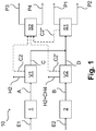
- the process 10 comprises a method 1 for propane dehydrogenation, a vapor cracking method 2, one or more first pre-separation steps V1, one or more second pre-separation steps V2, one or more first separation steps S1 and one or more second separation steps S2.
- the first pre-separation step (s) V1, the second pre-separation step (s) V2, the first separation step (s) S1 and the second separation step (s) S2 can each be grouped as desired and, for example, combined in corresponding system components.
- first pre-separation step (s) V1 and the second pre-separation step (s) V2 each run or are carried out separately from one another, ie that component mixtures that are fed to the first pre-separation step (s) are at least not at the same point how other component mixtures are fed to the second pre-separation step or steps and vice versa.
- the process 1 for propane dehydrogenation is fed with a first feed stream E1, which can in particular comprise propane.
- the process 1 for propane dehydrogenation is carried out in a manner known in principle, so that a first component mixture A is formed in it, which at least Contains hydrogen, ethane, ethylene, propane and propylene, and which can be carried out from process 1 for propane dehydrogenation in the form of a corresponding stream.
- Process 1 for propane dehydrogenation can in particular be carried out using one or more suitable reactors which can be constructed in a manner customary in the art.
- the first component mixture A or the corresponding material flow is at least partially fed to the first pre-separation step or steps V1 in which the first component mixture A or the corresponding material flow is subjected to a pressure increase and at least partial removal of hydrogen.
- this can be done in a basically known manner.
- the first component mixture A or the corresponding material flow can be liquefied in the first pre-separation step or steps V1.
- Separated hydrogen is illustrated in the form of a material flow labeled H2. At least partial removal of hydrocarbons with two carbon atoms is also possible, but optional, as illustrated by a stream C2 shown in dashed lines.
- a component mixture which is also referred to here as the third component mixture C and which can be carried out in the form of a corresponding material flow from the first pre-separation step or steps V1.
- Possible hydrogen contents of the third component mixture C or of the corresponding material flow have already been explained above.
- the third component mixture C, downstream of the first pre-separation step or steps V1 also contains hydrocarbons with three carbon atoms and smaller amounts of other components, for example hydrocarbons with two hydrocarbon atoms, if not removed, and hydrocarbons with four carbon atoms, which are used in process 1 for propane dehydrogenation as By-products are formed.
- first component mixture A also contains other components such as water and carbon dioxide, these can also be removed in the first pre-separation step or steps V1.
- a hydrocarbon-rich insert in the form of a material flow E2 is fed to the steam cracking process 2, which can also be carried out in a manner customary in the art, for example also using several cracking furnaces.
- the Hydrocarbon-rich use can in particular include naphtha and lighter hydrocarbons, but also heavy hydrocarbons.
- the hydrocarbon-rich use can also include paraffinic hydrocarbons with two, three and four carbon atoms, in particular ethane, propane and butane.
- the steam cracking process 2 as a whole or different cracking furnaces that are used in the steam cracking process 2 can also be supplied with different hydrocarbon feeds and processed there under different cracking conditions.
- the hydrocarbons of the hydrocarbon-rich feed (s) are at least partially converted so that a second component mixture B is obtained which contains at least hydrogen, methane, ethane, ethylene, propane and propylene.
- the second component mixture B can be withdrawn from the steam cracking process 2 in the form of a corresponding material flow and then at least partially fed to the one or more second pre-separation steps V2.
- the composition of the second component mixture B or of the corresponding material flow depends largely on the hydrocarbon-rich feed supplied to the steam cracking process 2.
- the second pre-separation step or steps V2 can in particular comprise a demethanization or a deethanization. With both options there is an increase in pressure.
- demethanization hydrogen is at least partially removed and methane is at least partially removed from the second component mixture B, as illustrated in the form of a material flow denoted by H2 + CH4.
- ethane and ethylene or, in general, hydrocarbons with two carbon atoms are not removed from the second component mixture B in this case.
- H2 + CH4 the material flow designated with H2 + CH4 is formed, but also at least partial removal of hydrocarbons with two carbon atoms.
- the latter is illustrated with the flow of material C2 'shown in dashed lines.
- the stream labeled H2 + CH4 leaves the top of a demethanization column, which is connected downstream of the deethanization column, or an apparatus assigned to the demethanization column, and the stream C2 'leaves its bottom.
- the stream labeled H2 + CH4 leaves the head of a demethanization column or an apparatus assigned to it, in the bottom of which, on the other hand, there is a component mixture which, in addition to hydrocarbons with two carbon atoms, also contains heavy hydrocarbons, so that stream C2 'Can not be withdrawn from the bottom of the demethanization column. This is taken off from the top of a deethanization column connected downstream of the demethanization column or an apparatus assigned to a deethanization column.
- the use of the second pre-separation step (s) forms a component mixture D, which is referred to here as the fourth component mixture, and which is at least depleted in hydrogen and methane compared to the second component mixture B, or that as a result is formed that at least hydrogen of methane are at least partially removed from the second component mixture B.
- This fourth component mixture can be withdrawn physically in the form of a corresponding material flow from the second pre-separation step or steps V2.
- the present invention also includes such a fourth component mixture D being present in a device used in the second pre-separation step or steps V2.
- the fourth component mixture D as explained several times, can be a liquid in the area of a separating tray near the sump of a demethanization or deethanization column, depending on whether a deethanizer-first process or a demethanizer-first process is used.
- this liquid is also depleted in the components explained above (hydrogen, methane and possibly hydrocarbons with two carbon atoms) or this liquid was formed by the fact that corresponding components were at least partially removed from the second component mixture B.
- the already mentioned third component mixture C can be fed to the area of the separating tray near the sump of a corresponding demethanization or deethanization column, so that the fourth component cannot be fed from the bottom of the demethanization or deethanization column Component mixture D but a further component mixture which results from the combination of the third component mixture C with the fourth component mixture D and the separating effect which is still present to a small extent in the area of the separating tray near the sump of the demethanization or deethanization column.
- the third component mixture C can, however, also be fed in downstream instead of into the region of the separating tray of the demethanization or deethanization column near the bottom.
- the first separation step (s) S1 are carried out in the course of the process 10, in which or in which two separation products are formed, namely a first separation product P1 and a second separation product P2.
- the first separation product P1 comprises predominantly or exclusively propylene, the second separation product P2 predominantly or exclusively propane.
- the second separation product P2 can in particular be fed back into the process 10.
- the first separation product P1 represents one of the products of process 10.
- the propylene of the first separation product P1 and the propane of the second separation product P2 originate at least partially from both the first component mixture A and the second component mixture B and thus also at least partially from both the third component mixture C and the fourth component mixture D.
- the present invention proposes an at least partially combined recovery of the first separation product P1 and the second separation product P2 from a first component mixture A originating from a process 1 for propane dehydrogenation and from a second component mixture B originating from a steam cracking process 2 or from third and fourth component mixtures formed therefrom C and D in front.
- the first separation steps S1 typically include in the last stage, as already explained several times, the use of a C3 splitter to which a mixture of predominantly or exclusively hydrocarbons with three carbon atoms, in particular propylene and propane, is fed.
- a corresponding hydrogenation can be provided upstream of a corresponding C3 splitter, as already mentioned.
- a depropanization can be provided, which can be carried out using a depropanization column.
- a component mixture which predominantly or exclusively contains hydrocarbons with three carbon atoms can be taken from a corresponding depropanization column or an apparatus assigned to the depropanization column, and a component mixture which contains heavier hydrocarbons can be taken from the bottom side.
- the component mixture withdrawn from the top of the depropanization column or the associated apparatus can, if appropriate after the optional hydrogenation mentioned, be fed to the C3 splitter.
- the depropanization can be preceded by a demethanization and a deethanization (in the case of a demethanizer-first process) or a deethanization (in the case of a deethanizer-first process) in the order given, the first separation step in each case according to these alternatives (demethanization in the demethanizer -First process or deethanization in the Deethanizer-First process) in the system used here at least partially represents a part of the second pre-separation step or steps V2 or one of the separation steps used here.
- a component mixture is withdrawn from a sump of a deethanization column used in the deethanization which predominantly or exclusively contains hydrocarbons with three or more carbon atoms. This is fed to the depropanization in each case. Further details are in the following Figure 2 explained.
- a bottom product of the demethanization is partially or completely fed to the deethanization, which is only depleted or freed from hydrogen and methane, but which still contains hydrocarbons with two or more carbon atoms.
- a top product of the deethanization is partially or completely fed to the demethanization, which contains hydrocarbons with two or fewer carbon atoms and hydrogen, while a bottom product of the deethanization, which contains hydrocarbons with three or more carbon atoms, is partially or completely the Depropanization fed.
- the third component mixture C can in particular be fed to the area of a tray near the sump of a demethanization column, the area of a tray near the sump of a deethanization column or a depropanization column, as already explained in detail above.
- the "common" separation proposed by the present invention begins at the respective feed point.
- the process 10 comprises one or more second separation steps S2, in which a third separation product P3 and a fourth separation product P4 are formed.
- the third separation product P3 comprises predominantly or exclusively ethylene
- the fourth separation product P4 comprises predominantly or exclusively ethane.
- Both the ethylene of the third separation product P3 and the ethane of the fourth separation product P4 originate at least partially from both the first component mixture A and from the second component mixture B and thus also at least partially from both the third component mixture C and from the fourth component mixture D.
- the fourth separation product P4 can be fed back into the process 10.
- the second separation step or steps can include the use of a C2 splitter into which a mixture of predominantly or exclusively hydrocarbons with two carbon atoms can be fed, in particular a mixture of ethylene and ethane.
- a mixture can be provided in particular in a deethanizer first process from the bottom of a demethanization column and in a demethanizer first process from the top of a deethanization column or an apparatus assigned to the deethanization column.
- the demethanization or the deethanization in the system used here can also be viewed at least partially as part of the second pre-separation step or steps V2.
- the subsequent deethanization can be systematically viewed as part of the first separation step or steps, so that, as shown here in the form of a material flow C2 ′′ shown in dashed lines, a material flow containing predominantly or exclusively hydrocarbons with two carbon atoms is formed only there Material flows C2 'and C2 ′′ are thus advantageously formed as alternatives to one another, and material flow C2 can be formed in addition to this.
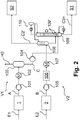
- FIG. 2 illustrates a process designed according to the invention in a simplified schematic representation, which, however, compared to the representation in Figure 1 Figure 10 shows further details of a specific embodiment.
- Structurally identical or comparable or functionally identical or comparable elements have identical reference symbols as in FIG Figure 1 and are not explained repeatedly for the sake of clarity.
- the first component mixture A is first compressed in a compressor 101 and then cooled in a heat exchanger 102.
- a compressor 101 In this case, at least some of the hydrocarbons with three and optionally two carbon atoms contained in the first component mixture A are condensed out.
- the first component mixture A which has been correspondingly compressed and cooled, can be transferred to a phase separator 103. From the head of the phase separator 103, the already in Figure 1 The flow of material shown and labeled H2 can be withdrawn.
- the third component mixture C which can be conveyed further by means of a pump 104, is withdrawn from the bottom of the phase separator 103.
- the second pre-separation step (s) V2 likewise initially comprises a compression of the second component mixture B using a compressor 105.
- the compression is followed by drying in a dryer 106.
- carbon dioxide can be removed before or between compression or drying (not shown in the picture). Downstream of the drying or removal of carbon dioxide, the second component mixture B is cooled using a heat exchanger 107.
- the illustrated embodiment uses a deethanizer-first method.
- the component mixture B is first fed into an absorber column 108, which is fed with a liquid reflux which is formed using an overhead gas of the actual deethanization column 109.
- a bottom product from the absorber column 108 is fed to the deethanization column.
- a liquid is formed in the area of a tray 109 'close to the sump, which liquid represents the fourth component mixture D in the system used here.
- the third component mixture C is fed in at this point.
- An overhead gas can be drawn off from the top of the deethanization column 109, which is operated with a bottom evaporator, liquefied in an overhead condenser designated 110 and a first part can be returned to the absorber column 108 and another part to the deethanization column 109.
- a stream containing predominantly or exclusively hydrocarbons with three or more carbon atoms can be withdrawn from the bottom of the deethanization column 109, which is designated here as C3 +, from the top of the absorber column 108 and thus as a gaseous fraction that is formed in the deethanization in Figure 1 illustrated stream C2 'are withdrawn.
- the former can be fed to the first separation step (s) S1, the latter to the second separation step (s) S2, the respective separation products P1 to P4 of which are shown in Figure 2 are not illustrated separately.
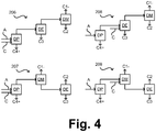
- a demethanizer-first process is used.
- the third component mixture C is fed into the area of a separating tray near the sump of a demethanization column used in the DM demethanization.
- the remaining steps of deethanization DE and depropanization DP follow in a manner known in principle.
- a demethanizer-first method is also used.
- the third component mixture is fed into the area of a separating tray near the sump of a demethanization column used in the DM demethanization.
- first the depropanization DP and then the deethanization DE follow, but likewise in a manner known in principle.
- a demethanizer-first process is also used in accordance with alternative 203, the sequence basically being the same as that in accordance with alternative 201, but the third component mixture C being fed into a depropanization column used in the depropanization DP.
- the top product of this depropanization could now also contain small amounts of hydrogen, methane and hydrocarbons with two carbon atoms, provided these were not completely removed from the component mixture C beforehand. These light components could then be removed via a stripper downstream of the subsequent hydrogenation.
- the top gas of this stripper which now contains the ethylene and the ethane from the first component mixture A, could then be fed directly to the second separation step (s) S2 or indirectly via recompression in the first pre-separation step (s) V1 or V2 to the second separation step (s) S2 become.
- deethanizer-first processes are used in each case, the deethanization DE being followed in each case by a demethanization DM and a depropanization DP in a manner known in principle.
- the alternatives 204 and 205 differ in the respective feed of the third component mixture C, which in alternative 204 is fed into the area of a separating tray near the sump of a demethanization column used in deethanization DE and in alternative 205 in a depropanization column used in depropanization DP.
- alternative 205 the same applies to the top product of this depropanization as for alternative 203.
- Figure 4 sets the representation of the Figure 3 continued, with Depropanizer-First methods being illustrated here in the form of alternatives 206 to 209.
- the third component mixture C is fed into a depropanization column used in the depropanization DP, in the alternative 208 in the area of a separating tray near the sump of a demethanization column used in the deethanization DE and in the alternative 209 in the area of a sump near dividing tray of a demethanization column used in the demethanization.
- the sequence of the remaining steps can be seen directly from the drawing.
- the small amounts of hydrocarbons with four carbon atoms come from component mixture C.
- the separation product P2 which is predominantly propane. This is not further critical provided the separation product P2 is used as a recycle for the steam cracking process.
- the component mixture C can also be fed in independently of the separation sequences described above upstream of the processing of hydrocarbons with three carbon atoms, for example before the hydrogenation of corresponding hydrocarbons (not shown in the graphic).
- the hydrocarbons with two or fewer carbon atoms would have to be fed to the second separation step or steps S2.
- small amounts of hydrocarbons with four or more carbon atoms in the separation product P2 would have to be tolerated, as described for alternatives 208 and 209.
Landscapes
- Chemical & Material Sciences (AREA)
- Organic Chemistry (AREA)
- Oil, Petroleum & Natural Gas (AREA)
- Engineering & Computer Science (AREA)
- Analytical Chemistry (AREA)
- Water Supply & Treatment (AREA)
- Chemical Kinetics & Catalysis (AREA)
- General Chemical & Material Sciences (AREA)
- Physics & Mathematics (AREA)
- Thermal Sciences (AREA)
- Organic Low-Molecular-Weight Compounds And Preparation Thereof (AREA)
- Production Of Liquid Hydrocarbon Mixture For Refining Petroleum (AREA)
Claims (14)
- Procédé (10) de production de propylène comprenant :- la mise en œuvre d'un procédé (1) de déshydrogénation du propane avec obtention d'un premier mélange de composants (A), lequel contient au moins de l'hydrogène, de l'éthane, de l'éthylène, du propane et du propylène,- la mise en œuvre d'un procédé de craquage à la vapeur (2) avec obtention un deuxième mélange de composants (B), lequel contient au moins de l'hydrogène, du méthane, de l'éthane, de l'éthylène, du propane et du propylène,- la formation d'un premier produit de séparation (P1), lequel contient au moins essentiellement du propylène, à l'aide d'au moins une partie du propylène du premier et du deuxième mélange de composants (A, B) et à l'aide d'une ou de plusieurs premières étapes de séparation (S1),- la formation d'un deuxième produit de séparation (P2), lequel contient au moins essentiellement du propane, à l'aide d'au moins une partie du propane du premier et du deuxième mélange de composants (A, B) et à l'aide de ladite ou desdites premières étapes de séparation (S1),- la formation d'un troisième produit de séparation (P3), lequel contient au moins essentiellement de l'éthylène, à l'aide d'au moins une partie de l'éthylène du premier et du deuxième mélange de composants (A, B) et à l'aide d'une ou de plusieurs deuxièmes étapes de séparation (S2),- la formation d'un quatrième produit de séparation (P4), lequel contient au moins essentiellement de l'éthane, à l'aide d'au moins une partie de l'éthane du premier et du deuxième mélange de composants (A, B) et à l'aide de ladite ou desdites deuxièmes étapes de séparation (S1) et
caractérisé en ce- qu'au moins une partie du premier mélange de composants (A) est soumise, avec obtention d'un troisième mélange de composants (C), à une ou plusieurs premières étapes de préséparation (V1), laquelle ou lesquelles comprennent une augmentation de pression et une élimination au moins partielle de l'hydrogène,- qu'au moins une partie du deuxième mélange de composants (B) est soumise, avec obtention d'un quatrième mélange de composants (D), à une ou plusieurs deuxièmes étapes de préséparation (V2), laquelle ou lesquelles comprennent une augmentation de pression, une élimination au moins partielle de l'hydrogène et une élimination au moins partielle du méthane et- qu'au moins une partie du troisième mélange de composants (C), ainsi qu'au moins une partie du quatrième mélange de composants (D) sont soumises conjointement à ladite ou auxdites premières étapes de séparation (S1). - Procédé (10) selon la revendication 1, selon lequel, lors de l'élimination de l'hydrogène et du méthane dans ladite ou lesdites deuxièmes étapes de préséparation (V2), l'éthane et l'éthylène sont également au moins essentiellement éliminés, l'élimination de l'hydrogène et du méthane dans ladite ou lesdites deuxièmes étapes de préséparation (V2), selon laquelle l'éthane et l'éthylène sont également au moins essentiellement éliminés, étant mise en œuvre à l'aide d'une colonne de déséthanisation (DE).
- Procédé (10) selon la revendication 2, selon lequel le troisième mélange de composants est injecté au moins partiellement à l'état liquide dans la zone d'un plateau de séparation proche du fond de la colonne de déséthanisation (DE).
- Procédé (10) selon la revendication 1, selon lequel, lors de l'élimination de l'hydrogène et du méthane dans ladite ou lesdites deuxièmes étapes de préséparation (V2), l'éthane et l'éthylène ne sont pas au moins essentiellement éliminés, l'élimination de l'hydrogène et du méthane dans ladite ou lesdites deuxièmes étapes de préséparation (V2), selon laquelle ou lesquelles l'éthane et l'éthylène ne sont pas au moins essentiellement éliminés, étant mise en œuvre à l'aide d'une colonne de déméthanisation (DM).
- Procédé (10) selon la revendication 4, selon lequel le troisième mélange de composants est injecté au moins partiellement à l'état liquide dans la zone d'un plateau de séparation à proximité du fond de la colonne de déméthanisation (DM).
- Procédé (10) selon la revendication 4 ou 5, selon lequel un liquide de fond est soutiré du bas de la colonne de déméthanisation (DM) et au moins partiellement transféré dans une colonne de déséthanisation (DM).
- Procédé (10) selon la revendication 2 ou 6, selon lequel un liquide de fond est soutiré du bas de la colonne de déséthanisation (DE) et au moins partiellement transféré dans une colonne de dépropanisation (DP).
- Procédé (10) selon la revendication 7, selon lequel le troisième mélange de composants est injecté au moins partiellement à l'état liquide dans la colonne de dépropanisation (DP).
- Procédé (10) selon la revendication 8, selon lequel une fraction contenant du propane et du propylène est soutirée de la tête de la colonne de dépropanisation (DP) ou d'un appareil affecté à la colonne de dépropanisation (DP) et est, avec addition d'hydrogène et avec obtention une fraction hydrogénée, au moins partiellement soumise à une hydrogénation, les composants à point d'ébullition inférieur à celui du propane et du propylène étant au moins partiellement éliminés de la fraction hydrogénée après l'hydrogénation.
- Procédé (10) selon l'une quelconque des revendications précédentes, selon lequel, dans ladite ou lesdites premières étapes de préséparation (V1) du premier mélange de composants, sa teneur en hydrogène est appauvrie à une valeur de 0 à 10 % en mole, en particulier de 0,1 à 5 % en mole, par exemple de 0,2 à 2 % en mole.
- Procédé (10) selon l'une quelconque des revendications précédentes, selon lequel ladite ou lesdites premières étapes de préséparation, à laquelle ou auxquelles le premier mélange de composants est soumis, comprennent l'augmentation de pression jusqu'à une pression absolue de 3 à 40 bars, en particulier de 10 à 30 bars, par exemple de 12 à 30 bars.
- Procédé (10) selon la revendication 11, selon lequel, dans ladite ou lesdites premières étapes de préséparation après l'augmentation de pression, une condensation au moins partielle des composants à point d'ébullition supérieur à celui de l'hydrogène est mise en œuvre.
- Installation de production de propylène comprenant :- une première unité de réacteur, laquelle est utilisée et conçue pour mettre en œuvre un procédé (1) de déshydrogénation du propane avec obtention d'un premier mélange de composants (A), lequel contient au moins de l'hydrogène, de l'éthane, de l'éthylène, du propane et du propylène,- une deuxième unité de réacteur, laquelle est utilisée et conçue pour mettre en œuvre un procédé de craquage à la vapeur (2) avec obtention d'un deuxième mélange de composants (B), lequel contient au moins de l'hydrogène, du méthane, de l'éthane, de l'éthylène, du propane et du propylène,- une première unité de séparation, laquelle est utilisée et conçue pour former un premier produit de séparation (P1), lequel contient au moins essentiellement du propylène, à l'aide d'au moins une partie du propylène du premier et du deuxième mélange de composants (A, B) et à l'aide d'une ou de plusieurs premières étapes de séparation (S1),- la première unité de séparation étant en outre utilisée et conçue pour former un deuxième produit de séparation (P2), lequel contient au moins essentiellement du propane, à l'aide d'au moins une partie du propane du premier et du deuxième mélange de composants (A, B) et à l'aide de ladite ou desdites premières étapes de séparation (S1),- une deuxième unité de séparation, laquelle est utilisée et conçue pour former un troisième produit de séparation (P3), lequel contient au moins essentiellement de l'éthylène, à l'aide d'au moins une partie de l'éthylène du premier et du deuxième mélange de composants (A, B) et à l'aide d'un ou de plusieurs deuxièmes étapes de séparation (S2),- la deuxième unité de séparation étant en outre utilisée et conçue pour former un quatrième produit de séparation (P4), lequel contient au moins essentiellement de l'éthane, à l'aide d'au moins une partie de l'éthane du premier et du deuxième mélange de composants (A, B) et à l'aide de ladite ou desdites étapes de séparation (S1) et
caractérisé par- une première unité de préséparation, laquelle est utilisée et conçue pour soumettre au moins une partie du premier mélange de composants (A), avec obtention d'un troisième mélange de composants (C), à une ou plusieurs premières étapes de préséparation (V1), laquelle ou lesquelles comprennent une augmentation de pression et une élimination au moins partielle de l'hydrogène,- une deuxième unité de préséparation, laquelle est utilisée et conçue pour soumettre au moins une partie du deuxième mélange de composants (B), avec obtention d'un quatrième mélange de composants (D), à une ou plusieurs deuxièmes étapes de préséparation (V2), laquelle ou lesquelles comprennent une augmentation de pression, une élimination au moins partielle de l'hydrogène et une élimination au moins partielle du méthane et- des moyens, lesquels sont utilisés et conçus pour alimenter au moins une partie du troisième mélange de composants (C) ainsi qu'au moins une partie du quatrième mélange de composants (D) conjointement à la première unité de séparation et pour les soumettre à ladite ou auxdites premières étapes de séparation (S1). - Procédé de modernisation d'une installation, laquelle est conçue pour mettre en œuvre un procédé de craquage à la vapeur à l'aide d'un certain nombre de composants d'installation, l'installation étant alimentée, avant la modernisation, en un mélange de départ contenant des hydrocarbures présentant une première composition, caractérisé en ce que la modernisation comprend l'alimentation de l'installation en, au lieu du mélange de départ contenant des hydrocarbures présentant la première composition, un mélange de départ contenant des hydrocarbures présentant une deuxième composition différente et l'utilisation d'un ou de plusieurs des composants d'installation pour, au lieu du procédé de craquage à la vapeur, un procédé de déshydrogénation du propane, un procédé selon l'une quelconque des revendications 1 à 12 étant mis en œuvre et/ou une installation selon la revendication 13 étant utilisée.
Applications Claiming Priority (2)
| Application Number | Priority Date | Filing Date | Title |
|---|---|---|---|
| EP17180974.2A EP3428143A1 (fr) | 2017-07-12 | 2017-07-12 | Procédé et installation de fabrication de propylène par combinaison de déshydrogénation de propane et procédé de vapocraquage avec stages de pre-séparation dans les deux procédés pour éliminer hydrogène et méthane |
| PCT/EP2018/068996 WO2019012062A1 (fr) | 2017-07-12 | 2018-07-12 | Procédé et installation de production de propylène par combinaison d'une déshydrogénation de propane et d'un procédé de vapocraquage comprenant des étapes de séparation préalable dans les deux procédés pour l'élimination partielle d'hydrogène et de méthane |
Publications (2)
| Publication Number | Publication Date |
|---|---|
| EP3652138A1 EP3652138A1 (fr) | 2020-05-20 |
| EP3652138B1 true EP3652138B1 (fr) | 2021-06-30 |
Family
ID=59337509
Family Applications (2)
| Application Number | Title | Priority Date | Filing Date |
|---|---|---|---|
| EP17180974.2A Withdrawn EP3428143A1 (fr) | 2017-07-12 | 2017-07-12 | Procédé et installation de fabrication de propylène par combinaison de déshydrogénation de propane et procédé de vapocraquage avec stages de pre-séparation dans les deux procédés pour éliminer hydrogène et méthane |
| EP18737312.1A Active EP3652138B1 (fr) | 2017-07-12 | 2018-07-12 | Procédé et installation de fabrication de propylène par combinaison de déshydrogénation de propane et procédé de vapocraquage avec stages de pre-séparation dans les deux procédés pour éliminer hydrogène et méthane |
Family Applications Before (1)
| Application Number | Title | Priority Date | Filing Date |
|---|---|---|---|
| EP17180974.2A Withdrawn EP3428143A1 (fr) | 2017-07-12 | 2017-07-12 | Procédé et installation de fabrication de propylène par combinaison de déshydrogénation de propane et procédé de vapocraquage avec stages de pre-séparation dans les deux procédés pour éliminer hydrogène et méthane |
Country Status (9)
| Country | Link |
|---|---|
| US (1) | US20200165177A1 (fr) |
| EP (2) | EP3428143A1 (fr) |
| KR (1) | KR20200026945A (fr) |
| CN (1) | CN110944967A (fr) |
| AU (1) | AU2018300042B2 (fr) |
| ES (1) | ES2886198T3 (fr) |
| PH (1) | PH12019502863A1 (fr) |
| RU (1) | RU2020101487A (fr) |
| WO (1) | WO2019012062A1 (fr) |
Families Citing this family (3)
| Publication number | Priority date | Publication date | Assignee | Title |
|---|---|---|---|---|
| US11198661B2 (en) * | 2019-09-10 | 2021-12-14 | Kellogg Brown & Root Llc | Process for recovery of propylene from a propane dehydrogenation process |
| CN111517908A (zh) * | 2020-05-20 | 2020-08-11 | 上海卓然工程技术股份有限公司 | 丙烷脱氢装置乙烯装置联产的工艺方法及系统 |
| EP3992172A1 (fr) * | 2020-10-29 | 2022-05-04 | Linde GmbH | Procédé et installation de production d'oléfines |
Family Cites Families (10)
| Publication number | Priority date | Publication date | Assignee | Title |
|---|---|---|---|---|
| US4458096A (en) | 1983-05-26 | 1984-07-03 | Air Products And Chemicals, Inc. | Process for the production of ethylene and propylene |
| AU3499095A (en) * | 1994-08-26 | 1996-03-22 | Exxon Chemical Patents Inc. | Process for selective hydrogenation of cracked hydrocarbons |
| DE102005053732A1 (de) * | 2005-11-10 | 2007-05-16 | Linde Ag | Verfahren zur Erhöhung der Propylenausbeute in Ethylenanlagen |
| US8563793B2 (en) | 2009-06-29 | 2013-10-22 | Uop Llc | Integrated processes for propylene production and recovery |
| CN103086826B (zh) * | 2011-10-28 | 2015-09-16 | 中国石油化工股份有限公司 | 一种乙烯和丙烯的联产方法 |
| CN102795956B (zh) * | 2012-08-30 | 2015-01-07 | 惠生工程(中国)有限公司 | 一种丙烷脱氢制丙烯反应产物的分离方法 |
| EP3312261B1 (fr) * | 2013-11-14 | 2021-07-14 | Linde GmbH | Procédé de séparation d'un mélange d'hydrocarbures |
| EA033166B1 (ru) | 2014-02-25 | 2019-09-30 | Сауди Бейсик Индастриз Корпорейшн | Способ конверсии углеводородов в олефины |
| CN104151121B (zh) * | 2014-08-13 | 2016-01-20 | 中石化上海工程有限公司 | Mto工艺与石脑油裂解前脱丙烷工艺耦合的方法 |
| CN104193570B (zh) * | 2014-08-13 | 2016-05-11 | 中石化上海工程有限公司 | Mto工艺与石脑油裂解顺序分离工艺耦合的方法 |
-
2017
- 2017-07-12 EP EP17180974.2A patent/EP3428143A1/fr not_active Withdrawn
-
2018
- 2018-07-12 WO PCT/EP2018/068996 patent/WO2019012062A1/fr unknown
- 2018-07-12 RU RU2020101487A patent/RU2020101487A/ru unknown
- 2018-07-12 EP EP18737312.1A patent/EP3652138B1/fr active Active
- 2018-07-12 AU AU2018300042A patent/AU2018300042B2/en active Active
- 2018-07-12 CN CN201880046144.7A patent/CN110944967A/zh active Pending
- 2018-07-12 US US16/630,323 patent/US20200165177A1/en not_active Abandoned
- 2018-07-12 KR KR1020207003322A patent/KR20200026945A/ko not_active Application Discontinuation
- 2018-07-12 ES ES18737312T patent/ES2886198T3/es active Active
-
2019
- 2019-12-18 PH PH12019502863A patent/PH12019502863A1/en unknown
Also Published As
| Publication number | Publication date |
|---|---|
| KR20200026945A (ko) | 2020-03-11 |
| RU2020101487A3 (fr) | 2022-03-09 |
| RU2020101487A (ru) | 2021-08-12 |
| CN110944967A (zh) | 2020-03-31 |
| EP3652138A1 (fr) | 2020-05-20 |
| ES2886198T3 (es) | 2021-12-16 |
| PH12019502863A1 (en) | 2020-12-07 |
| AU2018300042A1 (en) | 2020-01-16 |
| WO2019012062A1 (fr) | 2019-01-17 |
| AU2018300042B2 (en) | 2022-10-13 |
| US20200165177A1 (en) | 2020-05-28 |
| EP3428143A1 (fr) | 2019-01-16 |
Similar Documents
| Publication | Publication Date | Title |
|---|---|---|
| EP3029019B1 (fr) | Procédé de fabrication d'hydrocarbures | |
| DE2724365C3 (de) | Verfahren zum Trennen eines C4 -Kohlenwasserstoffgemisches durch extraktive Destillation | |
| EP3092052B1 (fr) | Procédé de séparation d'un mélange d'hydrocarbures contenant de l'hydrogène, dispositif de séparation et installation d'oléfine | |
| EP3652138B1 (fr) | Procédé et installation de fabrication de propylène par combinaison de déshydrogénation de propane et procédé de vapocraquage avec stages de pre-séparation dans les deux procédés pour éliminer hydrogène et méthane | |
| EP3313779B1 (fr) | Procede et installation de production d'hydrogene a partir un melange de charge contenant un hydrogene et des hydrocarbures | |
| EP3068849B1 (fr) | Procédé de séparation d'un mélange d'hydrocarbures | |
| EP3029402A1 (fr) | Procédé et système de traitement technique de séparation d'un courant de charge | |
| WO2013020675A1 (fr) | Séquence de séparation d'hydrocarbures provenant d'une dissociation thermique douce | |
| EP3652137B1 (fr) | Procédé et installation de fabrication de propylène par combinaison de déshydrogénation de propane et procédé de vapocraquage avec recyclage de propane au procédé de vapocraquage | |
| EP3510008B1 (fr) | Procédé et installation de production de benzène | |
| EP3550241A1 (fr) | Procédé et une installation de séparation d'un mélange d'hydrocarbures | |
| WO2017125435A1 (fr) | Procédé de production d'éthylène à partir de méthane | |
| EP3714023B1 (fr) | Procédé et installation permettant d'obtenir des composés aromatiques polymérisables | |
| EP3029018A1 (fr) | Procédé et installation de production de propylène | |
| EP3041916B1 (fr) | Procédé de production d'hydrocarbures | |
| WO2017037018A1 (fr) | Procédé et installation de traitement par séparation d'un mélange de départ | |
| WO2017125438A1 (fr) | Procédé de traitement par séparation d'un mélange gazeux | |
| EP3029017A1 (fr) | Procédé et système de fabrication d'hydrocarbures | |
| WO2019193187A1 (fr) | Procédé de séparation d'un mélange de composants et équipement de séparation | |
| EP2926882A1 (fr) | Procédé et installation de séparation d'un mélange gazeux et procédé de rééquipement d'une installation de séparation | |
| EP3350287B1 (fr) | Procédé et installation destinés au traitement technique de séparation d'hydrocarbures et de mélange de matière comprenant des combinaisons sulfurées | |
| DE102015208943A1 (de) | Verfahren und Anlage zur Bearbeitung eines Stoffgemischs | |
| DE102019115402A1 (de) | Verfahren und Anlage zur Gewinnung eines Olefins | |
| EP3940042A1 (fr) | Procédé et installation d'extraction d'hydrocarbures | |
| DE102019115382A1 (de) | Verfahren und Anlage zur Gewinnung eines oder mehrerer Olefine |
Legal Events
| Date | Code | Title | Description |
|---|---|---|---|
| STAA | Information on the status of an ep patent application or granted ep patent |
Free format text: STATUS: UNKNOWN |
|
| STAA | Information on the status of an ep patent application or granted ep patent |
Free format text: STATUS: THE INTERNATIONAL PUBLICATION HAS BEEN MADE |
|
| PUAI | Public reference made under article 153(3) epc to a published international application that has entered the european phase |
Free format text: ORIGINAL CODE: 0009012 |
|
| STAA | Information on the status of an ep patent application or granted ep patent |
Free format text: STATUS: REQUEST FOR EXAMINATION WAS MADE |
|
| 17P | Request for examination filed |
Effective date: 20200212 |
|
| AK | Designated contracting states |
Kind code of ref document: A1 Designated state(s): AL AT BE BG CH CY CZ DE DK EE ES FI FR GB GR HR HU IE IS IT LI LT LU LV MC MK MT NL NO PL PT RO RS SE SI SK SM TR |
|
| AX | Request for extension of the european patent |
Extension state: BA ME |
|
| RAP1 | Party data changed (applicant data changed or rights of an application transferred) |
Owner name: LINDE GMBH |
|
| DAV | Request for validation of the european patent (deleted) | ||
| DAX | Request for extension of the european patent (deleted) | ||
| REG | Reference to a national code |
Ref country code: DE Ref legal event code: R079 Ref document number: 502018005934 Country of ref document: DE Free format text: PREVIOUS MAIN CLASS: C07C0011060000 Ipc: C07C0005333000 |
|
| RIC1 | Information provided on ipc code assigned before grant |
Ipc: C07C 7/09 20060101ALI20201222BHEP Ipc: C10G 51/06 20060101ALI20201222BHEP Ipc: C07C 7/00 20060101ALI20201222BHEP Ipc: C07C 7/04 20060101ALI20201222BHEP Ipc: C07C 11/06 20060101ALI20201222BHEP Ipc: C10G 9/00 20060101ALI20201222BHEP Ipc: C07C 9/08 20060101ALI20201222BHEP Ipc: C07C 5/333 20060101AFI20201222BHEP Ipc: C10G 9/36 20060101ALI20201222BHEP |
|
| GRAP | Despatch of communication of intention to grant a patent |
Free format text: ORIGINAL CODE: EPIDOSNIGR1 |
|
| STAA | Information on the status of an ep patent application or granted ep patent |
Free format text: STATUS: GRANT OF PATENT IS INTENDED |
|
| INTG | Intention to grant announced |
Effective date: 20210204 |
|
| GRAS | Grant fee paid |
Free format text: ORIGINAL CODE: EPIDOSNIGR3 |
|
| GRAA | (expected) grant |
Free format text: ORIGINAL CODE: 0009210 |
|
| STAA | Information on the status of an ep patent application or granted ep patent |
Free format text: STATUS: THE PATENT HAS BEEN GRANTED |
|
| AK | Designated contracting states |
Kind code of ref document: B1 Designated state(s): AL AT BE BG CH CY CZ DE DK EE ES FI FR GB GR HR HU IE IS IT LI LT LU LV MC MK MT NL NO PL PT RO RS SE SI SK SM TR |
|
| REG | Reference to a national code |
Ref country code: CH Ref legal event code: EP |
|
| REG | Reference to a national code |
Ref country code: AT Ref legal event code: REF Ref document number: 1406241 Country of ref document: AT Kind code of ref document: T Effective date: 20210715 |
|
| REG | Reference to a national code |
Ref country code: DE Ref legal event code: R096 Ref document number: 502018005934 Country of ref document: DE |
|
| REG | Reference to a national code |
Ref country code: IE Ref legal event code: FG4D Free format text: LANGUAGE OF EP DOCUMENT: GERMAN |
|
| REG | Reference to a national code |
Ref country code: LT Ref legal event code: MG9D |
|
| PG25 | Lapsed in a contracting state [announced via postgrant information from national office to epo] |
Ref country code: FI Free format text: LAPSE BECAUSE OF FAILURE TO SUBMIT A TRANSLATION OF THE DESCRIPTION OR TO PAY THE FEE WITHIN THE PRESCRIBED TIME-LIMIT Effective date: 20210630 Ref country code: HR Free format text: LAPSE BECAUSE OF FAILURE TO SUBMIT A TRANSLATION OF THE DESCRIPTION OR TO PAY THE FEE WITHIN THE PRESCRIBED TIME-LIMIT Effective date: 20210630 Ref country code: BG Free format text: LAPSE BECAUSE OF FAILURE TO SUBMIT A TRANSLATION OF THE DESCRIPTION OR TO PAY THE FEE WITHIN THE PRESCRIBED TIME-LIMIT Effective date: 20210930 |
|
| REG | Reference to a national code |
Ref country code: NL Ref legal event code: MP Effective date: 20210630 |
|
| PG25 | Lapsed in a contracting state [announced via postgrant information from national office to epo] |
Ref country code: NO Free format text: LAPSE BECAUSE OF FAILURE TO SUBMIT A TRANSLATION OF THE DESCRIPTION OR TO PAY THE FEE WITHIN THE PRESCRIBED TIME-LIMIT Effective date: 20210930 Ref country code: LV Free format text: LAPSE BECAUSE OF FAILURE TO SUBMIT A TRANSLATION OF THE DESCRIPTION OR TO PAY THE FEE WITHIN THE PRESCRIBED TIME-LIMIT Effective date: 20210630 Ref country code: RS Free format text: LAPSE BECAUSE OF FAILURE TO SUBMIT A TRANSLATION OF THE DESCRIPTION OR TO PAY THE FEE WITHIN THE PRESCRIBED TIME-LIMIT Effective date: 20210630 Ref country code: SE Free format text: LAPSE BECAUSE OF FAILURE TO SUBMIT A TRANSLATION OF THE DESCRIPTION OR TO PAY THE FEE WITHIN THE PRESCRIBED TIME-LIMIT Effective date: 20210630 Ref country code: GR Free format text: LAPSE BECAUSE OF FAILURE TO SUBMIT A TRANSLATION OF THE DESCRIPTION OR TO PAY THE FEE WITHIN THE PRESCRIBED TIME-LIMIT Effective date: 20211001 |
|
| REG | Reference to a national code |
Ref country code: ES Ref legal event code: FG2A Ref document number: 2886198 Country of ref document: ES Kind code of ref document: T3 Effective date: 20211216 |
|
| PG25 | Lapsed in a contracting state [announced via postgrant information from national office to epo] |
Ref country code: CZ Free format text: LAPSE BECAUSE OF FAILURE TO SUBMIT A TRANSLATION OF THE DESCRIPTION OR TO PAY THE FEE WITHIN THE PRESCRIBED TIME-LIMIT Effective date: 20210630 Ref country code: SM Free format text: LAPSE BECAUSE OF FAILURE TO SUBMIT A TRANSLATION OF THE DESCRIPTION OR TO PAY THE FEE WITHIN THE PRESCRIBED TIME-LIMIT Effective date: 20210630 Ref country code: NL Free format text: LAPSE BECAUSE OF FAILURE TO SUBMIT A TRANSLATION OF THE DESCRIPTION OR TO PAY THE FEE WITHIN THE PRESCRIBED TIME-LIMIT Effective date: 20210630 Ref country code: RO Free format text: LAPSE BECAUSE OF FAILURE TO SUBMIT A TRANSLATION OF THE DESCRIPTION OR TO PAY THE FEE WITHIN THE PRESCRIBED TIME-LIMIT Effective date: 20210630 Ref country code: PT Free format text: LAPSE BECAUSE OF FAILURE TO SUBMIT A TRANSLATION OF THE DESCRIPTION OR TO PAY THE FEE WITHIN THE PRESCRIBED TIME-LIMIT Effective date: 20211102 Ref country code: EE Free format text: LAPSE BECAUSE OF FAILURE TO SUBMIT A TRANSLATION OF THE DESCRIPTION OR TO PAY THE FEE WITHIN THE PRESCRIBED TIME-LIMIT Effective date: 20210630 Ref country code: SK Free format text: LAPSE BECAUSE OF FAILURE TO SUBMIT A TRANSLATION OF THE DESCRIPTION OR TO PAY THE FEE WITHIN THE PRESCRIBED TIME-LIMIT Effective date: 20210630 |
|
| PG25 | Lapsed in a contracting state [announced via postgrant information from national office to epo] |
Ref country code: PL Free format text: LAPSE BECAUSE OF FAILURE TO SUBMIT A TRANSLATION OF THE DESCRIPTION OR TO PAY THE FEE WITHIN THE PRESCRIBED TIME-LIMIT Effective date: 20210630 |
|
| REG | Reference to a national code |
Ref country code: CH Ref legal event code: PL |
|
| REG | Reference to a national code |
Ref country code: DE Ref legal event code: R097 Ref document number: 502018005934 Country of ref document: DE |
|
| PG25 | Lapsed in a contracting state [announced via postgrant information from national office to epo] |
Ref country code: MC Free format text: LAPSE BECAUSE OF FAILURE TO SUBMIT A TRANSLATION OF THE DESCRIPTION OR TO PAY THE FEE WITHIN THE PRESCRIBED TIME-LIMIT Effective date: 20210630 |
|
| PG25 | Lapsed in a contracting state [announced via postgrant information from national office to epo] |
Ref country code: LI Free format text: LAPSE BECAUSE OF NON-PAYMENT OF DUE FEES Effective date: 20210731 Ref country code: DK Free format text: LAPSE BECAUSE OF FAILURE TO SUBMIT A TRANSLATION OF THE DESCRIPTION OR TO PAY THE FEE WITHIN THE PRESCRIBED TIME-LIMIT Effective date: 20210630 Ref country code: CH Free format text: LAPSE BECAUSE OF NON-PAYMENT OF DUE FEES Effective date: 20210731 |
|
| PLBE | No opposition filed within time limit |
Free format text: ORIGINAL CODE: 0009261 |
|
| STAA | Information on the status of an ep patent application or granted ep patent |
Free format text: STATUS: NO OPPOSITION FILED WITHIN TIME LIMIT |
|
| PG25 | Lapsed in a contracting state [announced via postgrant information from national office to epo] |
Ref country code: AL Free format text: LAPSE BECAUSE OF FAILURE TO SUBMIT A TRANSLATION OF THE DESCRIPTION OR TO PAY THE FEE WITHIN THE PRESCRIBED TIME-LIMIT Effective date: 20210630 Ref country code: LU Free format text: LAPSE BECAUSE OF NON-PAYMENT OF DUE FEES Effective date: 20210712 |
|
| 26N | No opposition filed |
Effective date: 20220331 |
|
| PG25 | Lapsed in a contracting state [announced via postgrant information from national office to epo] |
Ref country code: IT Free format text: LAPSE BECAUSE OF FAILURE TO SUBMIT A TRANSLATION OF THE DESCRIPTION OR TO PAY THE FEE WITHIN THE PRESCRIBED TIME-LIMIT Effective date: 20210630 Ref country code: IE Free format text: LAPSE BECAUSE OF NON-PAYMENT OF DUE FEES Effective date: 20210712 Ref country code: FR Free format text: LAPSE BECAUSE OF NON-PAYMENT OF DUE FEES Effective date: 20210830 |
|
| PG25 | Lapsed in a contracting state [announced via postgrant information from national office to epo] |
Ref country code: LT Free format text: LAPSE BECAUSE OF FAILURE TO SUBMIT A TRANSLATION OF THE DESCRIPTION OR TO PAY THE FEE WITHIN THE PRESCRIBED TIME-LIMIT Effective date: 20210630 |
|
| PG25 | Lapsed in a contracting state [announced via postgrant information from national office to epo] |
Ref country code: CY Free format text: LAPSE BECAUSE OF FAILURE TO SUBMIT A TRANSLATION OF THE DESCRIPTION OR TO PAY THE FEE WITHIN THE PRESCRIBED TIME-LIMIT Effective date: 20210630 |
|
| PG25 | Lapsed in a contracting state [announced via postgrant information from national office to epo] |
Ref country code: HU Free format text: LAPSE BECAUSE OF FAILURE TO SUBMIT A TRANSLATION OF THE DESCRIPTION OR TO PAY THE FEE WITHIN THE PRESCRIBED TIME-LIMIT; INVALID AB INITIO Effective date: 20180712 |
|
| PGFP | Annual fee paid to national office [announced via postgrant information from national office to epo] |
Ref country code: GB Payment date: 20230724 Year of fee payment: 6 Ref country code: ES Payment date: 20230821 Year of fee payment: 6 |
|
| PGFP | Annual fee paid to national office [announced via postgrant information from national office to epo] |
Ref country code: DE Payment date: 20230720 Year of fee payment: 6 Ref country code: BE Payment date: 20230719 Year of fee payment: 6 |
|
| PG25 | Lapsed in a contracting state [announced via postgrant information from national office to epo] |
Ref country code: MK Free format text: LAPSE BECAUSE OF FAILURE TO SUBMIT A TRANSLATION OF THE DESCRIPTION OR TO PAY THE FEE WITHIN THE PRESCRIBED TIME-LIMIT Effective date: 20210630 |