EP3652049B1 - Système de chenilles pour véhicule tracté - Google Patents
Système de chenilles pour véhicule tracté Download PDFInfo
- Publication number
- EP3652049B1 EP3652049B1 EP18831085.8A EP18831085A EP3652049B1 EP 3652049 B1 EP3652049 B1 EP 3652049B1 EP 18831085 A EP18831085 A EP 18831085A EP 3652049 B1 EP3652049 B1 EP 3652049B1
- Authority
- EP
- European Patent Office
- Prior art keywords
- trailing
- frame member
- assembly
- leading
- wheel
- Prior art date
- Legal status (The legal status is an assumption and is not a legal conclusion. Google has not performed a legal analysis and makes no representation as to the accuracy of the status listed.)
- Active
Links
- 230000000712 assembly Effects 0.000 claims description 86
- 238000000429 assembly Methods 0.000 claims description 86
- 238000005516 engineering process Methods 0.000 description 16
- 238000012986 modification Methods 0.000 description 6
- 230000004048 modification Effects 0.000 description 6
- 230000008901 benefit Effects 0.000 description 4
- 230000009471 action Effects 0.000 description 3
- 238000013016 damping Methods 0.000 description 3
- 238000010276 construction Methods 0.000 description 2
- 238000006073 displacement reaction Methods 0.000 description 2
- 239000002783 friction material Substances 0.000 description 2
- 239000000463 material Substances 0.000 description 2
- 239000002689 soil Substances 0.000 description 2
- 241001124569 Lycaenidae Species 0.000 description 1
- 229910000831 Steel Inorganic materials 0.000 description 1
- 230000006978 adaptation Effects 0.000 description 1
- 230000006835 compression Effects 0.000 description 1
- 238000007906 compression Methods 0.000 description 1
- 230000003247 decreasing effect Effects 0.000 description 1
- 229920001971 elastomer Polymers 0.000 description 1
- 239000000806 elastomer Substances 0.000 description 1
- 230000003116 impacting effect Effects 0.000 description 1
- 239000011499 joint compound Substances 0.000 description 1
- 238000012423 maintenance Methods 0.000 description 1
- 239000007769 metal material Substances 0.000 description 1
- 238000000034 method Methods 0.000 description 1
- 230000001483 mobilizing effect Effects 0.000 description 1
- 230000002028 premature Effects 0.000 description 1
- 239000012858 resilient material Substances 0.000 description 1
- 238000005096 rolling process Methods 0.000 description 1
- 239000004576 sand Substances 0.000 description 1
- 239000002210 silicon-based material Substances 0.000 description 1
- 239000007787 solid Substances 0.000 description 1
- 239000010959 steel Substances 0.000 description 1
Images


Classifications
-
- B—PERFORMING OPERATIONS; TRANSPORTING
- B60—VEHICLES IN GENERAL
- B60B—VEHICLE WHEELS; CASTORS; AXLES FOR WHEELS OR CASTORS; INCREASING WHEEL ADHESION
- B60B11/00—Units comprising multiple wheels arranged side by side; Wheels having more than one rim or capable of carrying more than one tyre
-
- A—HUMAN NECESSITIES
- A01—AGRICULTURE; FORESTRY; ANIMAL HUSBANDRY; HUNTING; TRAPPING; FISHING
- A01B—SOIL WORKING IN AGRICULTURE OR FORESTRY; PARTS, DETAILS, OR ACCESSORIES OF AGRICULTURAL MACHINES OR IMPLEMENTS, IN GENERAL
- A01B76/00—Parts, details or accessories of agricultural machines or implements, not provided for in groups A01B51/00 - A01B75/00
-
- B—PERFORMING OPERATIONS; TRANSPORTING
- B62—LAND VEHICLES FOR TRAVELLING OTHERWISE THAN ON RAILS
- B62D—MOTOR VEHICLES; TRAILERS
- B62D55/00—Endless track vehicles
- B62D55/06—Endless track vehicles with tracks without ground wheels
-
- B—PERFORMING OPERATIONS; TRANSPORTING
- B62—LAND VEHICLES FOR TRAVELLING OTHERWISE THAN ON RAILS
- B62D—MOTOR VEHICLES; TRAILERS
- B62D55/00—Endless track vehicles
- B62D55/08—Endless track units; Parts thereof
- B62D55/084—Endless-track units or carriages mounted separably, adjustably or extensibly on vehicles, e.g. portable track units
-
- B—PERFORMING OPERATIONS; TRANSPORTING
- B62—LAND VEHICLES FOR TRAVELLING OTHERWISE THAN ON RAILS
- B62D—MOTOR VEHICLES; TRAILERS
- B62D55/00—Endless track vehicles
- B62D55/08—Endless track units; Parts thereof
- B62D55/104—Suspension devices for wheels, rollers, bogies or frames
- B62D55/116—Attitude or position control of chassis by action on suspension, e.g. to compensate for a slope
-
- B—PERFORMING OPERATIONS; TRANSPORTING
- B62—LAND VEHICLES FOR TRAVELLING OTHERWISE THAN ON RAILS
- B62D—MOTOR VEHICLES; TRAILERS
- B62D55/00—Endless track vehicles
- B62D55/08—Endless track units; Parts thereof
- B62D55/18—Tracks
- B62D55/24—Tracks of continuously flexible type, e.g. rubber belts
-
- B—PERFORMING OPERATIONS; TRANSPORTING
- B60—VEHICLES IN GENERAL
- B60B—VEHICLE WHEELS; CASTORS; AXLES FOR WHEELS OR CASTORS; INCREASING WHEEL ADHESION
- B60B11/00—Units comprising multiple wheels arranged side by side; Wheels having more than one rim or capable of carrying more than one tyre
- B60B11/08—Arrangements of balancing mechanisms enabling a uniform distribution of load to tyres
-
- B—PERFORMING OPERATIONS; TRANSPORTING
- B60—VEHICLES IN GENERAL
- B60G—VEHICLE SUSPENSION ARRANGEMENTS
- B60G2200/00—Indexing codes relating to suspension types
- B60G2200/40—Indexing codes relating to the wheels in the suspensions
- B60G2200/46—Indexing codes relating to the wheels in the suspensions camber angle
-
- B—PERFORMING OPERATIONS; TRANSPORTING
- B60—VEHICLES IN GENERAL
- B60G—VEHICLE SUSPENSION ARRANGEMENTS
- B60G2204/00—Indexing codes related to suspensions per se or to auxiliary parts
- B60G2204/10—Mounting of suspension elements
- B60G2204/17—Mounting of bogies, e.g. for trailers
-
- B—PERFORMING OPERATIONS; TRANSPORTING
- B60—VEHICLES IN GENERAL
- B60G—VEHICLE SUSPENSION ARRANGEMENTS
- B60G2204/00—Indexing codes related to suspensions per se or to auxiliary parts
- B60G2204/40—Auxiliary suspension parts; Adjustment of suspensions
- B60G2204/41—Elastic mounts, e.g. bushings
-
- B—PERFORMING OPERATIONS; TRANSPORTING
- B60—VEHICLES IN GENERAL
- B60G—VEHICLE SUSPENSION ARRANGEMENTS
- B60G2204/00—Indexing codes related to suspensions per se or to auxiliary parts
- B60G2204/40—Auxiliary suspension parts; Adjustment of suspensions
- B60G2204/41—Elastic mounts, e.g. bushings
- B60G2204/4102—Elastic mounts, e.g. bushings having a pin or stud extending perpendicularly to the axis of the elastic mount
-
- B—PERFORMING OPERATIONS; TRANSPORTING
- B60—VEHICLES IN GENERAL
- B60G—VEHICLE SUSPENSION ARRANGEMENTS
- B60G2300/00—Indexing codes relating to the type of vehicle
- B60G2300/32—Track vehicles
-
- B—PERFORMING OPERATIONS; TRANSPORTING
- B60—VEHICLES IN GENERAL
- B60G—VEHICLE SUSPENSION ARRANGEMENTS
- B60G5/00—Resilient suspensions for a set of tandem wheels or axles having interrelated movements
- B60G5/01—Resilient suspensions for a set of tandem wheels or axles having interrelated movements the set being characterised by having more than two successive axles
-
- B—PERFORMING OPERATIONS; TRANSPORTING
- B62—LAND VEHICLES FOR TRAVELLING OTHERWISE THAN ON RAILS
- B62D—MOTOR VEHICLES; TRAILERS
- B62D63/00—Motor vehicles or trailers not otherwise provided for
- B62D63/06—Trailers
Definitions
- the present technology relates to track systems.
- Certain vehicles such as, for example, agricultural vehicles (e.g., harvesters, combines, tractors, agriculture implement, etc.) and construction vehicles (e.g., bulldozers, front-end loaders, etc.), are used to perform work on ground surfaces that are soft, slippery and/or uneven (e.g., soil, mud, sand, ice, snow, etc.).
- agricultural vehicles e.g., harvesters, combines, tractors, agriculture implement, etc.
- construction vehicles e.g., bulldozers, front-end loaders, etc.
- Track systems designed for towed vehicles have a frame connected to the towed vehicle's chassis, leading and trailing idler wheels rotatably connected at each end of the frame, and support wheels rotatably connected to the frame intermediate the idler wheels.
- Track systems for towed vehicles differ from other track systems designed for self-propelled vehicles in that they do not include a sprocket wheel and a gearbox that receives a drive shaft of the vehicle.
- Document US 2015/321708 discloses a mobile farm implement including a track assembly with a plurality of arms that are pivotally coupled to support idler wheels and bogie wheels such that the track assembly is able to better conform to the terrain when the implement is towed behind a tractor or otherwise moved.
- Document WO 2004/005118 discloses a wheel assembly for mobilizing a construction vehicle upon a base surface and including a frame connected with the vehicle and configured to pivot about a first axis. At least one and preferably two axles are connected with the frame and configured to pivot respectively about a second axis and a third axis, the second and third axes each extending generally perpendicularly with respect to the first axis. Each axle has a longitudinal centerline extending generally perpendicularly with respect to the second axis. Two wheels are preferably connected with each axle so as to rotate generally about each axle centerline.
- a vehicle wheel assembly which includes a vehicle frame having a first axle, a wheel assembly having a housing with an aperture engaging the first axle and enabling the wheel assembly to pivot in a first plane about a first axis formed by the first axle.
- a cylindrical member is carried by the housing of the wheel assembly, the cylindrical member and housing are arranged perpendicular to the first axle.
- a first wheel is pivotably connected to a first portion of the cylindrical member and a second wheel is pivotably connected to a second portion of the cylindrical member.
- the first wheel and second wheel independently pivot in a second plane about a second axis formed by the cylindrical member.
- the first axis is arranged perpendicular to the second axis and the first plane is arranged perpendicular to the second plane .”
- the structure described in United States Patent Number 8,763,716 B2 does not allow for the idler wheels, i.e. the fore and aft wheel assemblies that guide the endless track around the track system, to pivot about the roll axis to conform to the ground surface.
- This can become an issue when the towed vehicle travels, for example, on a road having a crown since a portion of the endless see page 3 track may not conform to the surface of the road when it passes under the fore and aft idler wheels.
- This can lead to premature wear of portions of the endless track or even to track blowout due to the increased pressure applied to at least some portion of the endless track when the track system travels on a road having a crown.
- a track system for use with a towed vehicle having a chassis and an axle extending laterally outwardly from the chassis suitable for connection to the track system.
- the track system includes an attachment assembly rotatably connectable to the axle of the vehicle and a multi-member frame assembly disposed laterally outwardly from the attachment assembly.
- the multi-member frame assembly includes a primary frame member connected to the attachment assembly, at least one wheel-bearing frame member pivotably connected to the primary frame member about a pivot located within a recess, and at least one resilient bushing assembly located within the recess and engaging the pivot.
- the at least one bushing assembly is resiliently deformable in a circumferential direction to permit pivoting of the pivot with respect to the recess.
- the at least one resilient bushing assembly is fixedly connected within the recess to resiliently bias the pivot towards a rest position with respect to the recess.
- the track system further includes a leading idler wheel assembly rotatably connected to the at least one wheel-bearing frame member. The leading idler wheel assembly pivots with respect to the primary frame member with the at least one wheel-bearing frame member.
- the track system further includes a trailing idler wheel assembly rotatably connected to the at least one wheel-bearing frame member. The trailing idler wheel assembly pivots with respect to the primary frame member with the at least one wheel-bearing frame member.
- the track system further includes an endless track extending around the primary frame member, the at least one wheel-bearing frame member, and the leading and trailing idler wheel assemblies.
- the track system can conform to a changing terrain advantageously compared to other track system where only the support wheels are pivotable about a longitudinal axis of the track system.
- having the leading and trailing idler wheel assemblies pivotable with respect to the primary frame member with the at least one wheel-bearing frame member may reduce wear of the endless track when the track system travels on a transversally inclined ground surface, such as a crowned road.
- the at least one wheel-bearing frame member is movable with respect the primary frame member via resilient deformation of the at least one bushing assembly in a radial direction.
- the track system further includes a plate having a vertically extending slotted hole.
- the plate is connected to the primary frame member.
- the pivot extends through the slotted hole of the plate, and the at least one wheel-bearing frame member is vertically movable with respect to the primary frame member via the resilient deformation of the at least one bushing assembly in the radial direction.
- the at least one wheel-bearing frame member is pivotable with respect to the primary frame member by an angle ranging between about -10 to +10 degrees with respect to the rest position.
- the track system further includes at least one support wheel assembly rotatably connected to the at least one wheel-bearing frame member.
- the at least one support wheel assembly is disposed intermediate the leading and trailing idler wheel assemblies.
- the at least one support wheel assembly pivots with respect to the primary frame member with the at least one wheel-bearing frame member.
- the primary frame member defines the recess.
- the recess extends along a longitudinal axis of the track system.
- the at least one bushing assembly defines a bushing axis.
- the bushing axis is coaxial with the longitudinal axis.
- the recess is a leading recess.
- the pivot is a leading pivot defined by a leading pin assembly.
- the at least one resilient bushing assembly is a leading resilient bushing assembly.
- the leading resilient bushing assembly is located within the leading recess.
- the leading pin assembly has a first portion engaging an inner surface of the leading bushing assembly and a second portion extending outside of the leading recess.
- the at least one wheel-bearing frame member is at least indirectly connected to the second portion of the leading pin assembly.
- the track system further includes a trailing recess defined by the primary frame member, a trailing pin assembly defining a trailing pivot, the at least one wheel-bearing frame member pivotably connected to the primary frame member about the trailing pivot located within the trailing recess, and a trailing resilient bushing assembly located within the trailing recess and engaging the trailing pivot.
- the at least one trailing resilient bushing assembly is resiliently deformable in a circumferential direction to permit pivoting of the trailing pivot with respect to the trailing recess.
- the trailing resilient bushing assembly is fixedly connected within the trailing recess to resiliently bias the trailing pivot towards a rest position with respect to the trailing recess.
- the trailing pin assembly has a first portion engaging an inner surface of the trailing resilient bushing assembly and a second portion extending outside of the trailing recess, and the at least one wheel-bearing frame member is at least indirectly connected to the second portion of the trailing pin assembly.
- the multi-member frame assembly includes a leading wheel-bearing frame member and a trailing wheel-bearing frame member.
- the leading wheel-bearing frame member is at least indirectly connected to the second portion of the leading pin assembly, and the trailing wheel-bearing frame member is at least indirectly connected to the second portion of the trailing pin assembly.
- leading and trailing wheel-bearing frame members are independently pivotable with respect to the primary frame member.
- leading and trailing wheel-bearing frame members are independently vertically movable with respect to the primary frame member.
- leading pin assembly is slidably engaged to the inner surface of the leading bushing assembly
- trailing pin assembly is slidably engaged to the inner surface of the trailing bushing assembly
- the track system further includes a threaded rod operatively connected to the first portions of the leading and trailing pin assemblies, and the leading and trailing wheel-bearing frame members are pivotable together with respect to the primary frame member.
- the multi-member frame assembly further includes a leading secondary frame member and a trailing secondary frame member.
- the leading secondary frame member is connected between the leading pin assembly and the leading wheel-bearing frame member.
- the trailing secondary frame member is connected between the trailing pin assembly and the trailing wheel-bearing frame member.
- leading wheel-bearing frame member is pivotably connected to the leading secondary frame member
- trailing wheel-bearing frame member is pivotably connected to the trailing secondary frame member
- the track system further includes a damper assembly pivotably connected between the leading secondary frame member and the trailing secondary frame member.
- the at least one bushing assembly includes an inner jacket, an outer jacket and a resilient bushing disposed between the inner and outer jackets.
- track system 40 a first embodiment of the present technology, track system 40, will be described. It is to be expressly understood that the track system 40 is merely an embodiment of the present technology. Thus, the description thereof that follows is intended to be only a description of illustrative examples of the present technology. This description is not intended to define the scope or set forth the bounds of the present technology. In some cases, what are believed to be helpful examples of modifications or alternatives to track system 40 may also be set forth below. This is done merely as an aid to understanding, and, again, not to define the scope or set forth the bounds of the present technology. These modifications are not an exhaustive list, and, as a person skilled in the art would understand, other modifications are likely possible.
- the track system 40 is for use with a towed vehicle 60 (schematically shown in Figures 1B to 1D ) having a chassis 62 and an axle 64 extending laterally outwardly from the chassis 62 for connection to the track system 40.
- the chassis 62 supports the various components of the towed vehicle 60.
- the towed vehicle 60 is an agricultural vehicle and supports agricultural implements such as planters, sprayers or similar devices.
- the track system 40 could be used on many different types of towed vehicles that serve many different functions.
- outwardly or “outward” means away from a longitudinal centerline 66 of the chassis 62 of the towed vehicle 60
- inwardly or “inward” means toward the longitudinal centerline 66.
- longitudinally means in a direction parallel to the longitudinal centerline 66 of the chassis 62 of the towed vehicle 60 in a plane parallel to flat level ground
- transversally means in a direction perpendicular to the longitudinal centerline 66 in a plane parallel to flat level ground
- vertical means in a direction perpendicular to the longitudinal centerline 66 along a height direction of the track system 40 in a plane perpendicular to flat level ground.
- a "+" symbol is used to indicate an axis of rotation.
- the term “axis” may be used to indicate an axis of rotation, or the term may refer to a "pivot joint” that includes all the necessary structure (bearing structures, pins, axles and other components) to permit a structure to pivot about such axis, as the case may be.
- the direction of forward travel of the track system 40 is indicated by an arrow 80 ( Figures 1A and 1B ).
- the "leading" components are identified with an “a” added to their reference numeral ( i.e .
- the track system 40 is configured to be attached to a right side of the chassis 62 of the vehicle 60.
- a track system 40' ( Figures 1B to 1D ), being another embodiment of the present technology and configured to be connected to a left side of the chassis 62 of the vehicle 60, is a mirror image of the track system 40 with the necessary adaptations, and the components of the track system 40' are identified with a " ' " added to their reference numeral. That embodiment will not be further described herein.
- the track system 40 has an attachment assembly 100 connectable to the axle 64 of the vehicle 60 and a multi-member frame assembly 160 disposed laterally outwardly of the attachment assembly 100.
- Leading and trailing idler wheel assemblies 360a, 360b also known in the art as guide wheels, are rotatably connected to the multi-member frame assembly 160 through leading and trailing idler axle assemblies 362a, 362b.
- Leading and trailing support wheel assemblies 390a, 390b are disposed intermediate the leading idler wheel assembly 360a and the trailing idler wheel assembly 360b, and are rotatably connected to the multi-member frame assembly 160 through leading and trailing support wheel axle assemblies 392a, 392b.
- the track system 40 further includes a tensioner 330 operatively connected to the multi-member frame assembly 160, and an endless track 480 extending around the multi-member frame assembly 160, the leading idler wheel assembly 360a, the trailing idler wheel assembly 360b, and the support wheel assemblies 390a, 390b.
- the endless track 480 is an endless polymeric track.
- the endless track 480 has an inner surface 482 engaging the leading idler wheel assembly 360a, the trailing idler wheel assembly 360b, and the leading and trailing support wheel assemblies 390a, 390b.
- Lugs 484 are disposed on a central portion of the inner surface 482.
- the leading and trailing idler and support wheel assemblies 360a, 360b, 390a, 390b have laterally spaced-apart wheels engaging the inner surface 482 of the endless track 480 on either side of the lugs 484.
- the endless track 480 also has an outer surface 486 with a tread 488 selected for ground engagement.
- the tread 488 varies in different embodiments according to the type of vehicle on which the track system 40 is to be used with and/or the type of ground surface on which the vehicle is destined to be towed. It is contemplated that within the scope of the present technology, the endless track 480 may be constructed of a wide variety of materials and structures including metallic components known in track systems. The specific properties and materials of the endless track 480 are not central to the present technology and will not be described in detail.
- the attachment assembly 100 includes a pillow block bearing assembly 102.
- the pillow block bearing assembly 102 has a bearing 104 having an axis 105, and a base 106 extending below the bearing 104.
- the axle 64 is coaxial with the axis 105, as best seen in Figures 1C and 1D , and is operatively connected to the bearing 104.
- the axle extends parallel to a plane 108 ( Figure 5 ) defined by the base 106.
- the track system 40 is rotatable about the axis 105 with respect to the chassis 62 of the vehicle 60 since the axle 64 is received within the bearing 104. As such, when the vehicle 60 is towed on a slopped terrain, the track system 40 can pitch positively or negatively about the axis 105 to conform to the contour of the terrain.
- the track system 40 further includes the multi-member frame assembly 160 disposed laterally outwardly of the attachment assembly 100.
- the multi-member frame assembly 160 supports the leading and trailing idler wheel assemblies 360a, 360b, and the leading and trailing support wheels 390a, 390b as will be described below.
- the multi-member frame assembly 160 includes a primary frame member 170 ( Figure 3 ) connected to the attachment assembly 100.
- the primary frame member 170 has an attachment portion 172 ( Figure 1A ), leading, intermediate and trailing arms 180a, 180, 180b connected to the attachment portion 172, and leading, intermediate and trailing portions 190a, 190, 190b that are connected to the arms 180a, 180, 180b.
- the primary frame member 170 shown in the present embodiment is unitary since the attachment portion 172, the arms 180a, 180, 180b and the portions 190a, 190, 190b are integrally formed, but in some embodiments, it is contemplated that the primary frame member 170 could be assembled from separate components connected together. In some embodiments, it is contemplated that the attachment assembly 100 could be integrally formed with the primary frame member 170.
- the attachment portion 172 is shaped and dimensioned to match the base 106 of the pillow block bearing assembly 102 ( Figure 7 ). A bolt pattern is defined in both the base 106 and the attachment portion 172. Fasteners 176 connect the base 106 to the attachment portion 172.
- the attachment assembly 100 could differ from the one shown in the Figures. It is contemplated that the bolt patterns defined in both the base 106 and the attachment portion 172 could include slotted holes so that the base 106 and the attachment portion 172 be angularly displaced with respect to one another about a vertically extending axis to select a toe-in or toe-out angle of the track system 40 and/or to select a tracking adjustment with respect to the forward direction of travel of the vehicle 60.
- the axle 64 is replaced by left and right axles (not shown) pivotally connected to the chassis 62 of the vehicle 60 about vertically extending axes (not shown).
- the pivoting of the left and right axles about the vertically extending axes would also permit the selection of a toe-in or toe-out angle for the track systems 40, 40' and/or to select a tracking adjustment with respect to the forward direction of travel of the vehicle 60.
- the attachment assembly 100 could be connected to a bottom face of the attachment portion 172.
- the axis 105 would extend below the plane 108 ( Figure 5 ).
- Other structures provided on the primary frame member 170 for selecting a toe-in or toe-out angle for the track systems 40, 40' and/or to select a tracking adjustment with respect to the forward direction of travel of the vehicle 60 are contemplated.
- leading, intermediate and trailing arms 180a, 180, 180b extend laterally outwardly from the attachment portion 172.
- Leading and trailing cavities 182a, 182b are formed between the leading, intermediate and trailing arms 180a, 180, 180b.
- the leading, intermediate and trailing arms 180a, 180, 180b are replaced by a single arm and the cavities 182a, 182b are absent.
- the leading, intermediate and trailing arms 180a, 180, 180b each have a depression 184a, 184, 184b defined therein.
- the cavities 182a, 182b between the arms 180a, 180, 180b and the depressions 184a, 184, 184b may assist in reducing the overall weight of the primary frame member 170 while substantially maintaining the structural properties of the primary frame member 170. These features may also assist the track system 40 to be efficiently mechanically packaged and/or reducing the volume of the track system 40, in embodiments where such is judged to be important.
- the primary frame member 170 further has leading and trailing portions 190a, 190b that extend longitudinally.
- the leading portion 190a has a recess 200a defined therein, and the trailing portion 190b has a recess 200b defined therein ( Figures 5 and 8 ).
- the recesses 200a, 200b extend longitudinally and are cylindrically shaped, but the recesses 200a, 200b could be shaped otherwise in other embodiments.
- the recesses 200a, 200b extend about a longitudinal axis 204 ( Figures 4 and 5 ) extending in the center of the recesses 200a, 200b.
- the longitudinal axis 204 is parallel to the longitudinal centerline 66 of the vehicle 60.
- a central recess 200 is defined between the leading and trailing portions 190a, 190b of the primary frame member 170. In some embodiments, the central recess 200 could be omitted.
- the central recess 200 is coaxial with the leading and trailing recesses 200a, 200b about the longitudinal axis 204.
- the trailing portion 190b has a shoulder 202b ( Figure 6 ) located at the leading end of the recess 200b that is next to the central recess 200.
- the leading portion 190a has a shoulder 202a ( Figure 5 ) located at the trailing end of the recess 200a that is next to the central recess 200.
- the leading and trailing portions 190a, 190b each have upwardly and downwardly extending protrusions 210a, 212a, 210b, 212b ( Figure 5 ).
- the downward protrusions 212a, 212b include a longitudinally extending threaded bore hole 214.
- Leading and trailing bushing assemblies 230a, 230b are received within the corresponding leading and trailing recesses 200a, 200b.
- the bushing assemblies 230a, 230b include resiliently deformable cylindrical bushings 232a, 232b, inner jackets 234a, 234b disposed radially inside the bushings 232a, 232b and outer jackets 236a, 236b disposed radially outside the bushings 232a, 232b.
- the bushings 232a, 232b are made of a resilient material, selected from, for example, an elastomer, a rubber- or a silicon-based material.
- the inner and outer jackets 234a, 234b, 236a, 236b are made of a metallic material, such as steel, and are fixedly connected to the inner and outer surfaces of the bushings 232a, 232b.
- the fixed connection means that the inner and outer jackets 234a, 234b, 236a, 236b cannot slip or rotate with respect to their corresponding surface of the bushings 232a, 232b.
- the bushings 232a, 232b and the inner and outer jackets 234a, 234b, 236a, 236b are fixedly connected using known bonding techniques.
- the bushings 232a, 232b have a thickness that is greater than that of the inner jackets 234a, 234b or the outer jackets 236a, 236b.
- the thickness of the bushings 232a, 232b and of the inner and outer jackets 234a, 234b, 236a, 236b may vary from what is shown in the Figures.
- the leading bushing assembly 230a is located within the leading recess 200a.
- the trailing bushing assembly 230b is located within the trailing recess 200b.
- Washers 240a, 240b are disposed between the leading and trailing bushing assemblies 230a, 230b and the shoulders 202a, 202b respectively.
- the washers 240a, 240b could be made of a wear resistant and low friction material. The washers 240a, 240b may reduce ingress of debris and dirt within the recesses 200a, 200b and may facilitate removal of the bushing assemblies 230a, 230b from the recesses 200a, 200b under some circumstances.
- a plate 250a is connected to the front end of the leading frame portion 190a, and a plate 250b is connected to the rear end of the trailing frame portion 190b.
- the plates 250a, 250b could also made of a wear resistant and low friction material.
- Each plate 250a, 250b has a through hole 252 ( Figure 8 ) allowing passage for a fastener 253 that is connectable to the threaded bore hole 214.
- the plates 250a, 250b further have a slotted hole 254 and a shoulder portion 256 extending around the slotted hole 254.
- the shoulder portion 256 of the plate 250a extends rearwardly from the plate 250a towards the front end of the bushing assembly 230a, and the shoulder portion 256 of the plate 250b extends forwardly from the plate 250b towards the rear end of the bushing assembly 230b.
- the bushing assemblies 230a, 230b extend between their corresponding plate 250a, 250b and washer 240a, 240b. As such, the bushing assemblies 230a, 230b cannot slide longitudinally in their respective recess 200a, 200b.
- the outer jacket 236b is fixedly connected to the trailing portion 190b of the primary frame member 170 within the recess 200b.
- the fixed connection of the outer jacket 236b to the trailing portion 190b provides that the outer jacket 236b is prevented from rotating with respect to the trailing portion 190b.
- the fixed connection of the outer jacket 236b with the trailing portion 190a is provided by press-fitting the bushing assembly 230b into the recess 200b. It is contemplated that the outer surface of the outer jacket 236b could also be bonded to the surface of the trailing portion 190b defining the recess 200b.
- the outer surface of the outer jacket 236b could include a longitudinally extending protrusion defining a key
- the surface of the trailing portion 190b defining the recess 200b could include a corresponding longitudinally extending slot, the protrusion and the recess forming a keyed connection preventing the rotation of the outer jacket 236b with respect to the surface of the trailing portion 190b defining the recess 200b.
- the outer jacket 236a is fixedly connected to the leading portion 190a in the leading recess 200a. The fixed connection of the outer jacket 236a to the leading portion 190a provides that the outer jacket 236a is prevented from rotating with respect to the leading portion 190a within the leading recess 200a.
- the multi-member frame assembly 160 further includes a pivot 260 defined by leading and trailing pin assemblies 270a, 270b.
- the pin assemblies 270a, 270b shown in the Figures include pins 271 that are solid pins, but the pins 271 could be hollow pins in other embodiments.
- the trailing pin assembly 270b has an outer surface 272b and has leading and trailing portions 274b, 276b. The trailing pin assembly 270b is received within the trailing bushing assembly 230b as the leading portion 274b of the trailing pin assembly 270b is engaged to an inner surface 235b of the inner jacket 234b.
- a recess 280b is defined in the leading portion 274b of the trailing pin assembly 270b.
- the trailing pin assembly 270b extends through the slotted hole 254 of the plate 250b and extends parallel to the longitudinal axis 204.
- the slotted hole 254 has a major axis 255 extending vertically with respect to the track system 40 and perpendicular to the longitudinal axis 204.
- the leading pin assembly 270a is received within the leading bushing assembly 230a as a trailing portion of the leading pin assembly 270b is engaged to an inner surface 235a of the inner jacket 234a.
- a recess 280a is defined in the trailing portion of the leading pin assembly 270a.
- the leading pin assembly 270a extends through the slotted hole 254 of the plate 250a and extends parallel to the longitudinal axis 204.
- the slotted hole 254 has its major axis (not shown) extending vertically with respect to the track system 40 and perpendicular to the longitudinal axis 204.
- the slotted hole 254 in the plates 250a, 250b could be circular.
- the bushing assemblies 230a, 230b and the pin assemblies 270a, 270b could differ from the ones shown in the Figures.
- the inner jacket 234b could be omitted and the bushing 232b could be integrally formed onto the leading portion 274b of the trailing pin 270b.
- the outer jacket 236b could be omitted and the bushing 232b could be molded into the recess 200b.
- the trailing portion 276b of the trailing pin assembly 270b supports a trailing frame member 290b that is part of the multi-member frame assembly 160.
- the trailing pin assembly 270b extends through an aperture 292b ( Figures 6 and 7 ) defined in the trailing frame member 290b.
- the trailing frame member 290b is fixedly connected to the trailing pin assembly 270b by fasteners 294b extending through a head portion of the trailing pin assembly 270b and fastened to threaded bore holes (not shown) defined in the trailing frame member 290b.
- the trailing frame member 290b has two upwardly extending arms 296b and one downwardly extending arm 298b ( Figure 6 ).
- the downwardly extending arm 298b includes a pivot assembly 300b having an axis 302b ( Figures 5 and 6 ).
- the pivot assembly 300b could include spherical bearings.
- a trailing tandem arm 310b is pivotally connected to the trailing frame member 290b at the pivot assembly 300b.
- the trailing tandem arm 310b has rear and front portions 312b, 314b.
- the trailing tandem arm 310b extends longitudinally fore and aft of the pivot assembly 300b.
- the trailing support wheel axle assembly 392b is connected to the front portion 314b of the trailing tandem arm 310b.
- leading and trailing tandem arms 310a, 310b may differ from the one shown in the Figures.
- a longitudinal distance between the pivot assembly 300b and the rear portion 312b could differ from another longitudinal distance between the pivot assembly 300b and the front portion 314b.
- other configurations of the tandem arms 310a, 310b are contemplated and could be used for selecting a load distribution on each one of the leading and trailing idler and support wheel assemblies 360a, 360b, 390a, 390b under some conditions.
- the trailing idler wheel axle assembly 362b defines an axis 364b.
- the trailing idler wheel axle assembly 362b and the axis 364b are transverse to the longitudinal axis 204.
- a wheel linkage 320 ( Figure 3 ) is operatively connected to the trailing idler wheel axle assembly 362b.
- the wheel linkage 320 has first and second portions 321, 323 positioned respectively below and above the trailing idler wheel axle assembly 362b.
- the first portion 321 is rotatably connected to the trailing tandem arm 310b at a pivot assembly 322 connected to the rear portion 312b.
- the tensioner 330 has first and second ends 332, 334.
- the first end 332 is rotatably connected to the arms 296b of the trailing frame member 290b at a pivot assembly 324. Having the tensioner 330 disposed above the trailing idler axle assembly 362b may assist in preventing debris from impacting the tensioner 330 when the track system 40 is in use.
- the second end 334 of the tensioner 330 is rotatably connected to the second portion 323 of the wheel linkage 320 at a pivot assembly 326.
- the pivot assembly 322 is downwardly offset from the axis 364b, and the pivot assembly 326 is upwardly offset from the axis 364b.
- the pivots 322, 326 are angularly displaced around the axis 364b such that the wheel linkage 320 forms a lever with the pivot 322 being the fulcrum thereof.
- the tensioner 330 and the wheel linkage 320 bias the trailing axle assembly 362b and the trailing idler wheel assembly 360b downwardly and towards the trailing end of the track system 40.
- the tensioner 330 selectively adjusts a tension in the endless track 480. Under some conditions, increasing the tension in the endless track 480 may assist in reducing the deformation of the endless track 480 under the wheel assemblies 360a, 360b, 390a, 390b when the track system 40 travels. Thus, under some conditions, increasing the tension in the endless track 480 may assist in reducing a rolling resistance of the track system 40. In other circumstances, decreasing the tension in the endless track 480 may facilitate removal and replacement of the endless track 480.
- the leading pin assembly 270a supports a leading frame member 290a that is also part of the multi-member frame assembly 160.
- the leading pin assembly 270a extends through an aperture 292a defined in the leading frame member 290a.
- the leading frame member 290a is fixedly connected to the leading pin assembly 270a by fasteners 294a extending through a head portion of the leading pin assembly 270a and fastened to threaded bore holes (not shown) defined in the leading frame member 290a.
- the leading frame member 290a has one downwardly extending arm 298a ( Figure 5 ).
- the downwardly extending arm 298a includes a pivot assembly 300a having an axis 302a.
- the pivot assembly 300a could include spherical bearings.
- a leading tandem arm 310a is pivotally connected to the leading frame member 290a at the pivot assembly 300a.
- the leading tandem arm 310a has rear and front portions 312a, 314a.
- the leading tandem arm 310a extends longitudinally fore and aft of the pivot assembly 300a.
- the leading support wheel assembly 390a includes a leading support wheel axle assembly 392a ( Figures 3 and 4 ) that is connected to the rear portion 312a of the leading tandem arm 310a.
- a leading idler wheel axle assembly 362a defining an axis 364a is connected to the front portion 314a of the leading tandem arm 310a.
- leading idler wheel axle assembly 362a and the axis 364a are transverse to the longitudinal axis 204.
- the track system 40 could have more than one support wheel assembly operatively connected to the leading and/or trailing tandem arms 310a, 310b.
- the motion dynamics of the track system 40 when travelling will be described.
- the entire track system 40 can pivot about the axis 105 to adopt a positive or negative pitch angle.
- the leading idler wheel assembly 360a can rise and fall as the front portion 314a of the leading tandem arm 310a is movable upwardly and downwardly because of the pivot assembly 300a.
- the rear portion 312a of the leading tandem arm 310a is movable upwardly and downwardly because of the pivot assembly 300a.
- the front portion 314b of the trailing tandem arm 310b is movable upwardly and downwardly because of the pivot assembly 300b.
- the rear portion 312b of the trailing tandem arm 310b is movable upwardly and downwardly because of the pivot assemblies 300b, 322, 324, 326.
- tandem arms 310a, 310b act as levers.
- each one of the wheel assemblies 360a, 360b, 390a, 390b can rise and fall independently.
- the vertical displacement of the primary frame member 170 is likely reduced compared to some other track systems having the idler and support wheel assemblies rotatably connected to the frame.
- the idler and support wheel assemblies 360a, 360b, 390a, 390b may move upwardly and downwardly repeatedly. This may induce vibrations in the leading and trailing frame members 290a, 290b and in their corresponding pin assemblies 270a, 290b. The vibrations induce the pin assemblies 270a, 290b to move vertically up and down repeatedly. Because of the clearance provided by the slotted holes 254 in the plates 250a, 250b and the resilience of the bushings 232a, 232b in a radial direction 206 ( Figure 8 ), the pin assemblies 270a, 270b are vertically movable along the major axis 255.
- the clearance provided by the slotted holes 254 in the plates 250a, 250b does not permit transversal displacement of the pin assemblies 270a, 270b, but this could be the case in other embodiments where the holes 254 would be circular.
- the bushings 232a, 232b are resiliently deformed in the radial direction 206 and they may dampen some of the vibrations transmitted by the pin assemblies 270a, 270b to the primary frame member 170.
- the amount of vibrations transmitted from the leading and trailing frame members 290a, 290b to the primary frame member 170 can be reduced because of the damping action of the bushing assemblies 230a, 230b.
- the bushing axis 207 is defined by the cylindrical inner surfaces 235a, 235b, and the bushing axis 207 extends coaxial with the axes of the cylindrical inner surfaces 235a, 235b.
- the bushing axis 207 is coaxial with the longitudinal axis 204, but the axes 204, 207 could extend parallel or be skewed with respect to each other under some conditions as will be described below.
- the leading and trailing idler and support wheel assemblies 360a, 360b, 390a, 390b of the track system 40 are thus capable of pivoting with respect to the primary frame member 170, and such pivoting corresponds to a roll motion about the bushing axis 207.
- This roll motion is represented by angle ⁇ in Figure 1C .
- the bushings 232a, 232b can withstand circumferential deformations of up to about 10 degrees, that is angle ⁇ equals to about 10 degrees, but larger or smaller angles ⁇ are contemplated in different embodiments.
- the track system 40 when the track system 40 travels on a transversally inclined ground surface G' shown in Figure 1D , which is a ground surface that is inclined transversally with respect to the longitudinal axis 204 and that defines a shallow ditch (or a trench), the leading and trailing idler and support wheel assemblies 360a, 360b, 390a, 390b are tilted laterally inwardly, and the track system 40 is capable of a roll motion about the bushing axis 207 represented by angle - ⁇ in Figure 1D . As such, the track system 40 has a range of roll motion about the bushing axis 207 from about -10 degrees to 10 degrees.
- the bushing assemblies 230a, 230b can be deformed simultaneously in the circumferential direction 208 and in the radial direction 206 by the pin assemblies 270a, 270b engaged thereto.
- the bushing axis 207 of the bushing assemblies 230a, 230b may be displaced from the longitudinal axis 204 under some conditions as the bushing assemblies 230a, 230b are resiliently deformed in the radial direction 206, and thus the bushing axis 207 may extend parallel to the longitudinal axis 204 or be skewed with respect to the longitudinal axis 204.
- the bushing assemblies 230a, 230b bias the pin assemblies 270a, 270b back to their rest position with respect to the primary frame member 170.
- the rest position corresponds to having the pin assemblies 270a, 270b rotated about the bushing axis 207 by about 0 degrees, that is angle ⁇ equals about 0 degrees, when the track system 40 is attached to the chassis 62, the vehicle 60 is in its operating condition, is at rest, is unloaded, and is disposed on flat level ground.
- each of the leading and trailing frame members 290a, 290b and their corresponding pin assembly 270a, 270b rotate independently about the longitudinal axis 204.
- the leading idler and support wheel assemblies 360a, 390a can be rotated about the longitudinal axis 204 independently of the trailing idler and support wheel assemblies 360b, 390b.
- the track system 40 can, under some conditions, maintain a more uniform contact of the endless track 480 with the ground surface and accommodate flexing and twisting of the endless track 480 when the track system 40 travels on changing terrain contours.
- the rotation of the idler and support wheel assemblies 360a, 360b, 390a, 390b about the longitudinal axis 204 may also assist in reducing wear of the tread 488 of the endless track 480 in the inward regions thereof when the track system 40 travels on a terrain such as the ground surface G of Figure 1C .
- leading and trailing pin assemblies 270a, 270b could be connected together by a rod assembly (not shown in this embodiment) received in and engaged to the recesses 280a, 280b ( Figure 5 ) defined in the pin assemblies 270a, 270b.
- a rod assembly (not shown in this embodiment) received in and engaged to the recesses 280a, 280b ( Figure 5 ) defined in the pin assemblies 270a, 270b.
- the leading and trailing pin assemblies 270a, 270b would act as a single pin assembly, and the leading and trailing frame members 290a, 290b could pivot in unison about the longitudinal axis 204.
- bushing assemblies 230a, 230b described above compared to using conventional bearings has the advantage of not requiring installing seals between the plates 250a, 250b and the bushing assemblies 230a, 230b as debris and dirt do not affect the radial and circumferential resilient deformation of the bushings 232a, 232b.
- using the bushing assemblies 230a, 230b may assist in reducing the maintenance costs of the track system 40 compared to other track systems using conventional bearings.
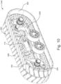
- the track system 1040 includes some elements that are the same as or similar to those described with reference to the track system 40. Therefore, for simplicity, elements of the track system 1040 that are the same as or similar to those of the track system 40 have been labeled with the same reference numerals, and will not be described again in detail, unless mentioned otherwise.
- the leading and trailing frame members 290a, 290b, and the leading and trailing tandem arms 310a, 310b are replaced by a single wheel-bearing frame member 1290.
- This feature may assist in allowing embodiments of the track system 1040 to be efficiently mechanically packaged, in embodiments where such is judged to be important.
- the wheel-bearing frame member 1290 extends longitudinally and is connected to the leading and trailing pin assemblies 270a, 270b ( Figure 13 ).
- the pivot assemblies 322, 324 are connected to the wheel-bearing frame member 1290.
- the wheel linkage 320 is rotatably connected to the pivot assembly 322, and the tensioner 330 is rotatably connected to the pivot assembly 324.
- the trailing idler wheel axle assembly 362b is operatively connected to the wheel linkage 320.
- the leading and trailing support wheel axle assemblies 392a, 392b are operatively connected to the wheel-bearing frame member 1290.
- the leading idler wheel axle assembly 362a is also operatively connected to the wheel-bearing frame member 1290.
- the wheel-bearing frame member 1290 extends longitudinally between the pivot 322 and the leading idler wheel axle assembly 362a.
- one or more additional support wheel assemblies could be disposed intermediate the leading and trailing support wheel assemblies 390a, 390b and operatively connected to the wheel-bearing frame member 1290.
- each one of the leading and trailing idler and support wheel assemblies 360a, 360b, 390a, 390b is operatively connected to the wheel-bearing frame member 1290, the wheel assemblies 360a, 360b, 390a, 390b pivot in unison with respect to the primary frame member 170 when a torque is applied to the leading and/or trailing pin assembly 270a, 270b about the longitudinal axis 204.
- the wheel assemblies 360a, 360b, 390a, 390b pivot in unison with respect to the primary frame member 170 when a torque is applied to the leading and/or trailing pin assembly 270a, 270b about the longitudinal axis 204.
- wheel assemblies 360a, 360b, 390a, 390b pivot in unison about the axis 105 ( Figure 9 ) defined by the attachment assembly 100 shown in Figures 1A to 8 .
- the leading and trailing idler and support wheel assemblies 360a, 360b, 390a, 390b may collectively pitch positively or negatively about the axis 105.
- the track system 2040 includes some elements that are the same as or similar to those described with reference to the track system 40. Therefore, for simplicity, elements of the track system 2040 that are the same as or similar to those of the track system 40 have been labeled with the same reference numerals, and will not be described again in detail, unless mentioned otherwise.
- the track system 2040 has a primary frame member 2170 having longitudinally extending recesses for receiving the bushing assemblies (only the bushing assembly 230a is shown in Figures 14 to 17 ) as described above with reference to the primary frame member 170.
- Leading and trailing pin assemblies 2270a, 2270b differ from the pin assemblies 270a, 270b in that they each have a pivot 2300a, 2300b defined in the head portion thereof.
- the pin assemblies 2270a, 2270b are slidably engaged to the corresponding inner surfaces 2235a, 2235b and are movable within their corresponding bushing assembly 2230a, 2230b along the bushing axis 207.
- the pivot 2300a has an axis 2302a and the pivot 2300b has an axis 2302b.
- a leading frame member 2290a is pivotally connected to the leading pin assembly 2270a at the pivot 2300a.
- a trailing frame member 2290b is pivotally connected to the trailing pin assembly 2270b at the pivot 2300b.
- the leading frame member 2290a is pivotally connected to a damper assembly 2500 at a pivot 2292a.
- the pivot 2292a has a play in it to permit rotation of the leading frame member 2290a about the bushing axis 206 as the leading pin assembly 2270a deforms the leading bushing assembly 2230a in the circumferential direction 208.
- the pivot 2292a could include a spherical bearing.
- the trailing frame member 2290b is pivotally connected to the damper assembly 2500 at a pivot 2292b.
- the pivot 2292b also has a play in it to permit rotation of the trailing frame member 2290b about the bushing axis 206 as the trailing pin assembly 2270a deforms the trailing bushing assembly 2230b in the circumferential direction 208.
- the pivot 2292b could also include a spherical bearing.
- the leading frame member 2290a is further pivotally connected to a leading tandem arm 2310a at a pivot 2294a.
- the leading idler wheel axle assembly 362a is operatively connected to a front portion 2314a of the leading tandem arm 2310a.
- the leading support wheel axle assembly 392a is operatively connected to a rear portion 2312a of the leading tandem arm 2310a.
- the trailing frame member 2290b is pivotally connected to a trailing tandem arm 2310b at a pivot 2294b.
- the trailing idler wheel axle assembly 362b is operatively connected to a rear portion 2312b of the trailing tandem arm 2310b.
- the trailing support wheel axle assembly 392b is operatively connected to a front portion 2314b of the trailing tandem arm 2310b.
- pivots 2294a, 2294b and the axes 2302a, 2302b could differ from what is shown in the Figures.
- a longitudinal distance between the axis 2302b and the pivot 2294b could differ from a longitudinal distance between the pivot 2294a and the axis 2302a.
- the pivoting motion of the leading and trailing frame members 2290a, 2290b could be limited by stops (not shown) mounted to the primary frame member 2170 and/or to the leading and trailing tandem arms 2310a, 2310b.
- a threaded rod 2400 is connected to a trailing end 2272a of the leading pin assembly 2270a and to a leading end 2272b of the trailing pin assembly 2270b.
- a nut 2402 is engaged to the threaded rod 2400. Moving the nut 2402 along the threaded rod 2400 permits to selectively adjust the spacing between the trailing end 2272a and the leading end 2272b as the pin assemblies 2270a, 2270b slide longitudinally with respect to their respective bushing assemblies 2230a, 2230b. Moving the nut 2402 thus selectively adjusts the spacing between the axes 2302a, 2302b. Selectively adjusting the spacing between the axes 2302a, 2302b permits to selectively adjust the tension within the endless track 480.
- the load of the weight of the vehicle 60 and its payload is transferred, in turn, to the primary frame member 2170, to the leading and trailing pin assemblies 2270a, 2270b via the bushing assemblies 2230a, 2230b, to the pivots 2300a, 2300b, and on to the leading and trailing frame members 2290a, 2290b.
- the pivots 2292a, 2292b tend to be pivoted downwardly about the axes 2302a, 2302b
- the pivots 2294a, 2294b tend to be pivoted upwardly about the axes 2302a, 2302b.
- the damper assembly 2500 is compressed between the pivots 2292a, 2292b.
- the damper assembly 2500 includes a hydro-pneumatic cylinder 2502.
- the damper assembly 2500 could further include a coil spring.
- the damper assembly 2500 resists the compression induced at the pivots 2292a, 2292b and biases the pivots 2292a, 2292b away from each other.
- the hydro-pneumatic cylinder 2502 provides for a damped pivotal motion of the leading and trailing frame members 2290a, 2290b with respect to each other about the axes 2302a, 2302b.
- the positioning of the damper assembly 2500 between the upper portions of the leading and trailing frame members 2290a, 2290b allows for a relatively long stroke of the cylinder 2502 of the damper assembly 2500.
- the damping action of the damper assembly 2500 is generally more refined than in other track systems where the stroke of a damping cylinder is relatively shorter.
- some of the vibrations that are caused by the unevenness of the ground surface on which the track system 2040 travels and that are transferred to the leading and trailing frame members 2290a, 2290b are dampened at least in part by the damper assembly 2500.
- the track system 2040 benefits from the combined actions of the damper assembly 2500, and of the bushing assemblies 2230a, 2230b that can deform along the radial direction 206 to dampen and/or absorb vibrations induced by the ground surface G, as described above.
- each one of the wheel assemblies 360a, 360b, 390a, 390b can rise and fall independently, and the pivotal motion of the leading and trailing frame members 2290a, 2290b is dampened by the damper assembly 2500.
Landscapes
- Engineering & Computer Science (AREA)
- Mechanical Engineering (AREA)
- Chemical & Material Sciences (AREA)
- Combustion & Propulsion (AREA)
- Transportation (AREA)
- Life Sciences & Earth Sciences (AREA)
- Soil Sciences (AREA)
- Environmental Sciences (AREA)
- Vehicle Body Suspensions (AREA)
- Platform Screen Doors And Railroad Systems (AREA)
- Tires In General (AREA)
Claims (15)
- Système de chenilles (40) destiné à être utilisé avec un véhicule tracté (60) ayant un châssis (62) et un essieu (64) s'étendant latéralement vers l'extérieur depuis le châssis et adapté pour être relié au système de chenilles, le système de chenilles comprenant :• un ensemble de fixation (100) pouvant être relié en rotation à l'essieu du véhicule ;• un ensemble de châssis à plusieurs éléments (160) disposé latéralement vers l'extérieur de l'ensemble de fixation, l'ensemble de châssis à plusieurs éléments comportant :∘ un élément de châssis principal (170) relié à l'ensemble de fixation ;∘ au moins un élément de châssis de roulement de roue (290a, 290b, 1290, 2310a, 2310b) relié de manière pivotante à l'élément de châssis principal autour d'un pivot (260) situé à l'intérieur d'un évidement (200a, 200b) ; le système de chenilles comprenant en outre :• un ensemble de roue folle avant (360a) relié en rotation à l'au moins un élément de châssis de roulement de roue, l'ensemble de roue folle avant pivotant par rapport à l'élément de châssis principal avec l'au moins un élément de châssis de roulement de roue ;• un ensemble de roue folle arrière (360b) relié en rotation à l'au moins un élément de châssis de roulement de roue, l'ensemble de roue folle arrière pivotant par rapport à l'élément de châssis principal avec l'au moins un élément de châssis de roulement de roue ; et• une chenille sans fin (480) s'étendant autour de l'élément de châssis principal, de l'au moins un élément de châssis de roulement de roue et des ensembles de roues folles avant et arrière,caractérisé en ce que l'ensemble de châssis à éléments multiples comporte en outre au moins un ensemble de douille élastique (230a, 230b, 2230a, 2230b) situé à l'intérieur de l'évidement et venant en prise avec le pivot, l'au moins un ensemble de douille étant élastiquement déformable dans une direction circonférentielle (208) pour permettre le pivotement du pivot par rapport à l'évidement, l'au moins un ensemble de douille élastique étant relié de manière fixe à l'intérieur de l'évidement pour solliciter de manière élastique le pivot vers une position de repos par rapport à l'évidement.
- Système de chenilles selon la revendication 1, dans lequel l'au moins un élément de châssis de roulement de roue est mobile par rapport à l'élément de châssis principal via une déformation élastique de l'au moins un ensemble de douille dans une direction radiale (206).
- Système de chenilles selon la revendication 2, comprenant en outre une plaque (250a, 250b) ayant un trou oblong s'étendant verticalement (254), la plaque étant reliée à l'élément de châssis principal, le pivot s'étendant à travers le trou oblong de la plaque, et l'au moins un élément de châssis de roulement de roue étant mobile verticalement par rapport à l'élément de châssis principal via la déformation élastique de l'au moins un ensemble de douille dans la direction radiale.
- Système de chenilles selon l'une quelconque des revendications 1 à 3, dans lequel l'au moins un élément de châssis de roulement de roue peut pivoter par rapport à l'élément de châssis principal d'un angle (θ) compris entre environ -10 et +10 degrés par rapport à la position de repos.
- Système de chenilles selon l'une quelconque des revendications 1 à 4, comprenant en outre au moins un ensemble de roues de support (390a, 390b) relié en rotation à l'au moins un élément de châssis de roulement de roue, l'au moins un ensemble de roues de support étant disposé entre les ensembles de roues folles avant et arrière, l'au moins un ensemble de roues de support pivotant par rapport à l'élément de châssis principal avec l'au moins un élément de châssis de roulement de roue.
- Système de chenilles selon l'une quelconque des revendications 1 à 5, dans lequel l'élément de châssis principal définit l'évidement, l'évidement s'étendant le long d'un axe longitudinal (204) du système de chenilles, et éventuellement, l'au moins un ensemble de douille définit un axe de douille (207), l'axe de douille étant coaxial à l'axe longitudinal.
- Système de chenilles selon la revendication 6, dans lequel :• l'évidement est un évidement avant (200a),• le pivot est un pivot avant défini par un ensemble de broche avant (270a, 2270a),• l'au moins un ensemble de douille élastique est un ensemble de douille élastique avant (230a, 2230a),• l'ensemble de douille élastique avant est situé à l'intérieur de l'évidement avant,• l'ensemble de broche avant a une première partie venant en prise avec une surface intérieure (235a) de l'ensemble de douille avant et une seconde partie s'étendant à l'extérieur de l'évidement avant, et• l'au moins un élément de châssis de roulement de roue est au moins indirectement relié à la seconde partie de l'ensemble de broche avant ; etcomprenant en outre :• un évidement arrière (200b) défini par l'élément de châssis principal,• un ensemble de broche arrière (270b, 2270b) définissant un pivot arrière, l'au moins un élément de châssis de roulement de roue étant relié de manière pivotante à l'élément de châssis principal autour du pivot arrière situé à l'intérieur de l'évidement arrière,• un ensemble de douille élastique arrière (230b, 2230b) situé à l'intérieur de l'évidement arrière et venant en prise avec le pivot arrière, l'au moins un ensemble de douille élastique arrière étant élastiquement déformable dans la direction circonférentielle pour permettre le pivotement du pivot arrière par rapport à l'évidement arrière, l'ensemble de douille élastique arrière étant relié de manière fixe à l'intérieur de l'évidement arrière pour solliciter de manière élastique le pivot arrière vers une position de repos par rapport à l'évidement arrière,• l'ensemble de broche arrière ayant une première partie (274b) venant en prise avec une surface interne (235b) de l'ensemble de douille élastique arrière et une seconde partie (276b) s'étendant à l'extérieur de l'évidement arrière, et• l'au moins un élément de châssis de roulement de roue étant au moins indirectement relié à la seconde partie de l'ensemble de broche arrière.
- Système selon la revendication 7, dans lequel :l'ensemble de châssis à éléments multiples (160) comporte un élément de châssis de roulement de roue avant (290a, 2310a) etun élément de châssis de roulement de roue arrière (290b, 2310b) ;l'élément de châssis de roulement de roue avant est au moins indirectement relié à la seconde partie de l'ensemble de broche avant ; etl'élément de châssis de roulement de roue arrière est au moins indirectement relié à la seconde partie de l'ensemble de broche arrière.
- Système de chenilles selon la revendication 8, dans lequel les éléments de châssis de roulement de roue avant et arrière peuvent au moins :pivoter indépendamment par rapport à l'élément de châssis principal, etse déplacer verticalement de manière indépendante par rapport à l'élément de châssis principal.
- Système de chenilles selon l'une quelconque des revendications 7 à 9, dans lequel l'ensemble de broche avant est mis en prise de manière coulissante sur la surface intérieure de l'ensemble de douille avant, et l'ensemble de broche arrière est mis en prise de manière coulissante sur la surface intérieure de l'ensemble de douille arrière.
- Système de chenilles selon la revendication 7, comprenant en outre une tige filetée (2400) reliée de manière opérationnelle aux premières parties des ensembles de broches avant et arrière, et dans lequel les éléments de châssis de roulement de roue avant et arrière peuvent pivoter ensemble par rapport à l'élément de châssis principal.
- Système de chenilles selon l'une quelconque des revendications 7 à 11, dans lequel l'ensemble de châssis à éléments multiples comporte en outre :• un élément de châssis secondaire avant (2290a) et un élément de châssis secondaire arrière (2290b) ;• l'élément de châssis secondaire avant étant relié entre l'ensemble de broche avant et l'élément de châssis de roulement de roue avant ; et• l'élément de châssis secondaire arrière étant relié entre l'ensemble de broche arrière et l'élément de châssis de roulement de roue arrière.
- Système de chenilles selon la revendication 12, dans lequel :• l'élément de châssis de roulement de roue avant est relié de manière pivotante à l'élément de châssis secondaire avant ; et• l'élément de châssis de roulement de roue arrière est relié de manière pivotante à l'élément de châssis secondaire arrière.
- Système de chenilles selon la revendication 12 ou 13, comprenant en outre un ensemble amortisseur (2500) relié de manière pivotante entre l'élément de châssis secondaire avant et l'élément de châssis secondaire arrière.
- Système de chenilles selon l'une quelconque des revendications 1 à 14, dans lequel l'au moins un ensemble de douille comporte une chemise intérieure (234a, 234b), une chemise extérieure (236a, 236b) et une douille élastique (232a, 232b) disposée entre les chemises intérieure et extérieure.
Applications Claiming Priority (2)
| Application Number | Priority Date | Filing Date | Title |
|---|---|---|---|
| US201762530937P | 2017-07-11 | 2017-07-11 | |
| PCT/IB2018/055123 WO2019012453A2 (fr) | 2017-07-11 | 2018-07-11 | Système de chenilles pour véhicule tracté |
Publications (3)
| Publication Number | Publication Date |
|---|---|
| EP3652049A2 EP3652049A2 (fr) | 2020-05-20 |
| EP3652049A4 EP3652049A4 (fr) | 2021-04-14 |
| EP3652049B1 true EP3652049B1 (fr) | 2023-05-03 |
Family
ID=65001569
Family Applications (1)
| Application Number | Title | Priority Date | Filing Date |
|---|---|---|---|
| EP18831085.8A Active EP3652049B1 (fr) | 2017-07-11 | 2018-07-11 | Système de chenilles pour véhicule tracté |
Country Status (4)
| Country | Link |
|---|---|
| US (1) | US11299220B2 (fr) |
| EP (1) | EP3652049B1 (fr) |
| CA (1) | CA3066319C (fr) |
| WO (1) | WO2019012453A2 (fr) |
Families Citing this family (2)
| Publication number | Priority date | Publication date | Assignee | Title |
|---|---|---|---|---|
| WO2017139356A2 (fr) * | 2016-02-08 | 2017-08-17 | Camso Inc. | Véhicule à chenilles avec espacement de piste réglable |
| CA3164806A1 (fr) * | 2020-01-23 | 2021-07-29 | Yves SAUVAGEAU | Ensemble chassis suspendu pour systeme de chenille |
Family Cites Families (57)
| Publication number | Priority date | Publication date | Assignee | Title |
|---|---|---|---|---|
| US1450466A (en) | 1923-04-03 | Fornia | ||
| US1785124A (en) | 1928-04-07 | 1930-12-16 | Walter H Stiemke | Hauling unit |
| US1953051A (en) | 1930-10-01 | 1934-03-27 | Linn Trailer Corp | Trailer construction |
| US1953053A (en) | 1931-02-14 | 1934-03-27 | Linn Trailer Corp | Trailer construction |
| US2070015A (en) | 1935-03-25 | 1937-02-09 | Linn Mfg Corp | Track trailer |
| US2082920A (en) | 1935-12-24 | 1937-06-08 | Aulmont W Tye | Trailer |
| US3096840A (en) * | 1960-05-25 | 1963-07-09 | Gen Motors Corp | Tractor suspension permitting pivotal movement of track frames |
| CH454049A (it) * | 1966-04-16 | 1968-03-31 | Beltrami Osmano | Escavatore |
| US3790230A (en) | 1969-09-12 | 1974-02-05 | Outboard Marine Corp | All-terrain vehicle |
| US3913987A (en) | 1974-02-21 | 1975-10-21 | Caterpillar Tractor Co | Track type tractors having resiliently mounted track roller assemblies |
| NO780692L (no) | 1978-02-28 | 1979-08-29 | Braathen Thor F | Leddet, terrenggaaende motorkjoeretoey |
| US4923257A (en) | 1989-04-13 | 1990-05-08 | Caterpillar Inc. | Belted vehicle suspension system |
| US5409305A (en) | 1992-08-17 | 1995-04-25 | Deere & Company | Undercarriage for a track laying vehicle |
| US5286044A (en) | 1993-01-29 | 1994-02-15 | Caterpillar Inc. | Belted multi-purpose trailer |
| AU694380B2 (en) | 1995-10-18 | 1998-07-16 | Kabushiki Kaisha Toyoda Jidoshokki Seisakusho | Crawler apparatus for vehicle |
| US5899543A (en) | 1997-02-14 | 1999-05-04 | Case Corporation | Resilient support element for roller wheels of a rubber tracked vehicle |
| US5899542A (en) | 1997-02-14 | 1999-05-04 | Case Corporation | Support system for roller wheels of rubber tracked vehicle |
| US20010007234A1 (en) | 1999-02-19 | 2001-07-12 | Scheetz Technology, Inc. | Apparatus and method for real time adjustment of a fifth wheel associated with an agricultural machine |
| US7740084B2 (en) * | 2000-05-02 | 2010-06-22 | Lyn Rosenboom | Agricultural implement frame, track assembly and cart |
| US7726749B2 (en) | 2001-05-02 | 2010-06-01 | Lyn Rosenboom | Track assembly with bogie wheel structure |
| WO2003076217A2 (fr) | 2002-03-08 | 2003-09-18 | Honda Giken Kogyo Kabushiki Kaisha | Suspension independante pour vehicule polyvalent |
| US7644788B2 (en) | 2002-06-27 | 2010-01-12 | Scheetz Inc. | Tensioning and suspension system for a trailer |
| US6712549B2 (en) | 2002-07-09 | 2004-03-30 | Blaw-Knox Construction Equipment Corporation | Double-axis oscillating bogie wheels |
| US7077216B2 (en) | 2003-10-21 | 2006-07-18 | Ati, Inc. | Earth scraper with track apparatus |
| EP1917161B9 (fr) | 2005-04-19 | 2010-08-04 | James M. Baxter | Remorques ameliorees |
| US7533741B2 (en) * | 2006-02-09 | 2009-05-19 | Glen Brazier | Swivel mounted track frame |
| WO2008073990A2 (fr) | 2006-12-12 | 2008-06-19 | Loegering Mfg. Inc. | Système de conversion d'un véhicule à roue |
| ITMN20080012A1 (it) | 2008-06-05 | 2009-12-06 | Tidue S R L | Cingolatura di movimentazione di macchina operatrice su terreno |
| DE102008053538A1 (de) | 2008-10-28 | 2010-04-29 | Claas Selbstfahrende Erntemaschinen Gmbh | Dolly-Achse und diese verwendender Fahrzeugverband |
| US7992504B2 (en) | 2009-02-10 | 2011-08-09 | Thurston Manufacturing Company | Farm implement with coupling device |
| JP2010274872A (ja) | 2009-06-01 | 2010-12-09 | Komatsu Ltd | 履帯式走行車両の転輪 |
| WO2011041704A1 (fr) | 2009-10-01 | 2011-04-07 | Camoplast Inc. | Ensemble chenille pour la traction d'un véhicule |
| US8613486B2 (en) | 2009-11-09 | 2013-12-24 | Caterpillar Inc. | Bushing for a track-type undercarriage |
| US20130181431A1 (en) | 2010-01-19 | 2013-07-18 | Balzer, Inc. | Self-steering agriculture grain carts and manure tanks |
| US8783796B2 (en) | 2010-06-18 | 2014-07-22 | Caterpillar Inc. | Pin for use in track rollers and bogie assemblies |
| WO2013026022A1 (fr) * | 2011-08-18 | 2013-02-21 | Caterpillar Inc. | Palier élastomère pour barre de stabilisation de train roulant |
| CA2878285C (fr) | 2012-07-06 | 2020-08-25 | Mtd Products Inc | Pignon d'entrainement pour un vehicule utilitaire a chenilles |
| US9452796B2 (en) | 2012-07-30 | 2016-09-27 | Cnh Industrial America Llc | Suspension system for a tracked work vehicle |
| WO2014022043A1 (fr) | 2012-07-30 | 2014-02-06 | Cnh America Llc | Ensemble goupille pour système de suspension de véhicule de chantier à chenilles |
| WO2014022044A1 (fr) | 2012-07-30 | 2014-02-06 | Cnh America Llc | Système de train de roulement pour véhicule de chantier à chenille |
| CH707606A1 (de) | 2013-02-05 | 2014-08-15 | Studersond Ag | Fahrzeug. |
| SE539473C2 (sv) | 2013-05-08 | 2017-09-26 | BAE Systems Hägglunds AB | Fjädringsanordning för bandgående fordon |
| US9457850B2 (en) | 2013-06-14 | 2016-10-04 | Unverferth Manufacturing Co., Inc. | Dual track |
| WO2015052310A1 (fr) | 2013-10-11 | 2015-04-16 | Franz Aunkofer | Véhicule auxiliaire agricole non entraîné, procédé permettant son utilisation pour des transports de charges agricoles et ensemble de traction agricole |
| US9457854B2 (en) | 2014-04-02 | 2016-10-04 | Unverferth Manufacturing Co., Inc. | Track assembly for farm implement |
| DE102014115112B4 (de) | 2014-10-17 | 2019-06-13 | Titan Intertractor GmbH | Fahrwerk für Kettenfahrzeuge |
| US10266215B2 (en) * | 2015-01-02 | 2019-04-23 | Camso Inc. | Track system for traction of an off-road vehicle |
| US10647367B2 (en) | 2015-02-18 | 2020-05-12 | Camso Inc. | Track system for traction of a vehicle |
| DE102015109112A1 (de) | 2015-06-09 | 2016-12-15 | Wacker Neuson Linz Gmbh | Baufahrzeug mit verkippbarem Fahrgestell |
| US10035551B2 (en) * | 2015-06-19 | 2018-07-31 | Delve Equipment, LLC | Tracked vehicle suspension systems and methods |
| DE102015010804A1 (de) | 2015-08-21 | 2017-02-23 | Fachhochschule Aachen | Befahranlage für zylindrische und/oder konische Oberflächen |
| US20170057572A1 (en) | 2015-08-28 | 2017-03-02 | Caterpillar Inc. | Track Joint Assembly |
| US10370046B2 (en) | 2016-01-22 | 2019-08-06 | NORWOOD SALES, Inc. | Track undercarriage camber stop method |
| WO2017139356A2 (fr) | 2016-02-08 | 2017-08-17 | Camso Inc. | Véhicule à chenilles avec espacement de piste réglable |
| US9688322B1 (en) | 2016-04-07 | 2017-06-27 | Cnh Industrial America Llc | Implement steerable track assembly with pivoting steering actuator |
| US9682736B1 (en) | 2016-04-07 | 2017-06-20 | Cnh Industrial America Llc | Implement steerable track assembly pivotable about three axes |
| US20180029652A1 (en) | 2016-07-26 | 2018-02-01 | Caterpillar Inc. | Arrangement for coupling main frame with equalizer bar of a machine |
-
2018
- 2018-07-11 EP EP18831085.8A patent/EP3652049B1/fr active Active
- 2018-07-11 US US16/619,787 patent/US11299220B2/en active Active
- 2018-07-11 CA CA3066319A patent/CA3066319C/fr active Active
- 2018-07-11 WO PCT/IB2018/055123 patent/WO2019012453A2/fr unknown
Also Published As
| Publication number | Publication date |
|---|---|
| US11299220B2 (en) | 2022-04-12 |
| EP3652049A4 (fr) | 2021-04-14 |
| CA3066319C (fr) | 2023-08-29 |
| WO2019012453A2 (fr) | 2019-01-17 |
| US20200122796A1 (en) | 2020-04-23 |
| WO2019012453A3 (fr) | 2019-02-21 |
| CA3066319A1 (fr) | 2019-01-17 |
| EP3652049A2 (fr) | 2020-05-20 |
Similar Documents
| Publication | Publication Date | Title |
|---|---|---|
| US10202154B2 (en) | Suspension and lock-out systems for a partially tracked vehicle | |
| EP3458342B1 (fr) | Système de chenille | |
| US10112663B1 (en) | Track assembly for traction of an off-road vehicle | |
| CA2878283C (fr) | Systemes de suspension et de verrouillage pour un vehicule a chenilles | |
| US10668962B2 (en) | Track system | |
| EP3494032B1 (fr) | Système de chenilles pour engin de chantier | |
| US11814118B2 (en) | Suspended undercarriage assembly for a track system | |
| EP3652049B1 (fr) | Système de chenilles pour véhicule tracté | |
| US20240025496A1 (en) | Pivot assembly for a ground-contacting wheel assembly | |
| US20230089165A1 (en) | Suspended undercarriage assembly for a track system | |
| EP3606807B1 (fr) | Système chenillé | |
| US11618515B2 (en) | Suspension system for a track-driven work vehicle with tandem rear idler/roller | |
| WO2023193117A1 (fr) | Système de courroie et courroie sans fin | |
| CA3199191A1 (fr) | Systeme de chenille a caracteristiques multiples presentant un rendement ameliore | |
| CA3085034A1 (fr) | Bloc-pivot pour ensemble roue en contact avec le sol |
Legal Events
| Date | Code | Title | Description |
|---|---|---|---|
| STAA | Information on the status of an ep patent application or granted ep patent |
Free format text: STATUS: THE INTERNATIONAL PUBLICATION HAS BEEN MADE |
|
| PUAI | Public reference made under article 153(3) epc to a published international application that has entered the european phase |
Free format text: ORIGINAL CODE: 0009012 |
|
| STAA | Information on the status of an ep patent application or granted ep patent |
Free format text: STATUS: REQUEST FOR EXAMINATION WAS MADE |
|
| 17P | Request for examination filed |
Effective date: 20200211 |
|
| AK | Designated contracting states |
Kind code of ref document: A2 Designated state(s): AL AT BE BG CH CY CZ DE DK EE ES FI FR GB GR HR HU IE IS IT LI LT LU LV MC MK MT NL NO PL PT RO RS SE SI SK SM TR |
|
| AX | Request for extension of the european patent |
Extension state: BA ME |
|
| DAV | Request for validation of the european patent (deleted) | ||
| DAX | Request for extension of the european patent (deleted) | ||
| A4 | Supplementary search report drawn up and despatched |
Effective date: 20210315 |
|
| RIC1 | Information provided on ipc code assigned before grant |
Ipc: B62D 55/00 20060101AFI20210309BHEP Ipc: B62D 55/06 20060101ALI20210309BHEP Ipc: B62D 55/08 20060101ALI20210309BHEP |
|
| REG | Reference to a national code |
Ref country code: DE Ref legal event code: R079 Ref document number: 602018049349 Country of ref document: DE Free format text: PREVIOUS MAIN CLASS: B62D0055000000 Ipc: A01B0076000000 |
|
| GRAP | Despatch of communication of intention to grant a patent |
Free format text: ORIGINAL CODE: EPIDOSNIGR1 |
|
| STAA | Information on the status of an ep patent application or granted ep patent |
Free format text: STATUS: GRANT OF PATENT IS INTENDED |
|
| RIC1 | Information provided on ipc code assigned before grant |
Ipc: B62D 55/116 20060101ALI20221025BHEP Ipc: B62D 55/06 20060101ALI20221025BHEP Ipc: B62D 63/06 20060101ALI20221025BHEP Ipc: B62D 55/24 20060101ALI20221025BHEP Ipc: B62D 55/084 20060101ALI20221025BHEP Ipc: B60G 5/01 20060101ALI20221025BHEP Ipc: B60B 11/08 20060101ALI20221025BHEP Ipc: B60B 11/00 20060101ALI20221025BHEP Ipc: A01B 76/00 20060101AFI20221025BHEP |
|
| INTG | Intention to grant announced |
Effective date: 20221122 |
|
| GRAS | Grant fee paid |
Free format text: ORIGINAL CODE: EPIDOSNIGR3 |
|
| GRAA | (expected) grant |
Free format text: ORIGINAL CODE: 0009210 |
|
| STAA | Information on the status of an ep patent application or granted ep patent |
Free format text: STATUS: THE PATENT HAS BEEN GRANTED |
|
| AK | Designated contracting states |
Kind code of ref document: B1 Designated state(s): AL AT BE BG CH CY CZ DE DK EE ES FI FR GB GR HR HU IE IS IT LI LT LU LV MC MK MT NL NO PL PT RO RS SE SI SK SM TR |
|
| REG | Reference to a national code |
Ref country code: GB Ref legal event code: FG4D |
|
| REG | Reference to a national code |
Ref country code: AT Ref legal event code: REF Ref document number: 1563814 Country of ref document: AT Kind code of ref document: T Effective date: 20230515 Ref country code: CH Ref legal event code: EP |
|
| REG | Reference to a national code |
Ref country code: DE Ref legal event code: R096 Ref document number: 602018049349 Country of ref document: DE |
|
| REG | Reference to a national code |
Ref country code: IE Ref legal event code: FG4D |
|
| P01 | Opt-out of the competence of the unified patent court (upc) registered |
Effective date: 20230513 |
|
| REG | Reference to a national code |
Ref country code: LT Ref legal event code: MG9D |
|
| REG | Reference to a national code |
Ref country code: NL Ref legal event code: MP Effective date: 20230503 |
|
| REG | Reference to a national code |
Ref country code: AT Ref legal event code: MK05 Ref document number: 1563814 Country of ref document: AT Kind code of ref document: T Effective date: 20230503 |
|
| PG25 | Lapsed in a contracting state [announced via postgrant information from national office to epo] |
Ref country code: SE Free format text: LAPSE BECAUSE OF FAILURE TO SUBMIT A TRANSLATION OF THE DESCRIPTION OR TO PAY THE FEE WITHIN THE PRESCRIBED TIME-LIMIT Effective date: 20230503 Ref country code: PT Free format text: LAPSE BECAUSE OF FAILURE TO SUBMIT A TRANSLATION OF THE DESCRIPTION OR TO PAY THE FEE WITHIN THE PRESCRIBED TIME-LIMIT Effective date: 20230904 Ref country code: NO Free format text: LAPSE BECAUSE OF FAILURE TO SUBMIT A TRANSLATION OF THE DESCRIPTION OR TO PAY THE FEE WITHIN THE PRESCRIBED TIME-LIMIT Effective date: 20230803 Ref country code: NL Free format text: LAPSE BECAUSE OF FAILURE TO SUBMIT A TRANSLATION OF THE DESCRIPTION OR TO PAY THE FEE WITHIN THE PRESCRIBED TIME-LIMIT Effective date: 20230503 Ref country code: ES Free format text: LAPSE BECAUSE OF FAILURE TO SUBMIT A TRANSLATION OF THE DESCRIPTION OR TO PAY THE FEE WITHIN THE PRESCRIBED TIME-LIMIT Effective date: 20230503 Ref country code: AT Free format text: LAPSE BECAUSE OF FAILURE TO SUBMIT A TRANSLATION OF THE DESCRIPTION OR TO PAY THE FEE WITHIN THE PRESCRIBED TIME-LIMIT Effective date: 20230503 |
|
| PGFP | Annual fee paid to national office [announced via postgrant information from national office to epo] |
Ref country code: GB Payment date: 20230711 Year of fee payment: 6 |
|
| PG25 | Lapsed in a contracting state [announced via postgrant information from national office to epo] |
Ref country code: RS Free format text: LAPSE BECAUSE OF FAILURE TO SUBMIT A TRANSLATION OF THE DESCRIPTION OR TO PAY THE FEE WITHIN THE PRESCRIBED TIME-LIMIT Effective date: 20230503 Ref country code: PL Free format text: LAPSE BECAUSE OF FAILURE TO SUBMIT A TRANSLATION OF THE DESCRIPTION OR TO PAY THE FEE WITHIN THE PRESCRIBED TIME-LIMIT Effective date: 20230503 Ref country code: LV Free format text: LAPSE BECAUSE OF FAILURE TO SUBMIT A TRANSLATION OF THE DESCRIPTION OR TO PAY THE FEE WITHIN THE PRESCRIBED TIME-LIMIT Effective date: 20230503 Ref country code: LT Free format text: LAPSE BECAUSE OF FAILURE TO SUBMIT A TRANSLATION OF THE DESCRIPTION OR TO PAY THE FEE WITHIN THE PRESCRIBED TIME-LIMIT Effective date: 20230503 Ref country code: IS Free format text: LAPSE BECAUSE OF FAILURE TO SUBMIT A TRANSLATION OF THE DESCRIPTION OR TO PAY THE FEE WITHIN THE PRESCRIBED TIME-LIMIT Effective date: 20230903 Ref country code: HR Free format text: LAPSE BECAUSE OF FAILURE TO SUBMIT A TRANSLATION OF THE DESCRIPTION OR TO PAY THE FEE WITHIN THE PRESCRIBED TIME-LIMIT Effective date: 20230503 Ref country code: GR Free format text: LAPSE BECAUSE OF FAILURE TO SUBMIT A TRANSLATION OF THE DESCRIPTION OR TO PAY THE FEE WITHIN THE PRESCRIBED TIME-LIMIT Effective date: 20230804 |
|
| PGFP | Annual fee paid to national office [announced via postgrant information from national office to epo] |
Ref country code: FR Payment date: 20230710 Year of fee payment: 6 Ref country code: DE Payment date: 20230710 Year of fee payment: 6 |
|
| PG25 | Lapsed in a contracting state [announced via postgrant information from national office to epo] |
Ref country code: FI Free format text: LAPSE BECAUSE OF FAILURE TO SUBMIT A TRANSLATION OF THE DESCRIPTION OR TO PAY THE FEE WITHIN THE PRESCRIBED TIME-LIMIT Effective date: 20230503 |
|
| PG25 | Lapsed in a contracting state [announced via postgrant information from national office to epo] |
Ref country code: SK Free format text: LAPSE BECAUSE OF FAILURE TO SUBMIT A TRANSLATION OF THE DESCRIPTION OR TO PAY THE FEE WITHIN THE PRESCRIBED TIME-LIMIT Effective date: 20230503 |
|
| PG25 | Lapsed in a contracting state [announced via postgrant information from national office to epo] |
Ref country code: SM Free format text: LAPSE BECAUSE OF FAILURE TO SUBMIT A TRANSLATION OF THE DESCRIPTION OR TO PAY THE FEE WITHIN THE PRESCRIBED TIME-LIMIT Effective date: 20230503 Ref country code: SK Free format text: LAPSE BECAUSE OF FAILURE TO SUBMIT A TRANSLATION OF THE DESCRIPTION OR TO PAY THE FEE WITHIN THE PRESCRIBED TIME-LIMIT Effective date: 20230503 Ref country code: RO Free format text: LAPSE BECAUSE OF FAILURE TO SUBMIT A TRANSLATION OF THE DESCRIPTION OR TO PAY THE FEE WITHIN THE PRESCRIBED TIME-LIMIT Effective date: 20230503 Ref country code: EE Free format text: LAPSE BECAUSE OF FAILURE TO SUBMIT A TRANSLATION OF THE DESCRIPTION OR TO PAY THE FEE WITHIN THE PRESCRIBED TIME-LIMIT Effective date: 20230503 Ref country code: DK Free format text: LAPSE BECAUSE OF FAILURE TO SUBMIT A TRANSLATION OF THE DESCRIPTION OR TO PAY THE FEE WITHIN THE PRESCRIBED TIME-LIMIT Effective date: 20230503 Ref country code: CZ Free format text: LAPSE BECAUSE OF FAILURE TO SUBMIT A TRANSLATION OF THE DESCRIPTION OR TO PAY THE FEE WITHIN THE PRESCRIBED TIME-LIMIT Effective date: 20230503 |
|
| REG | Reference to a national code |
Ref country code: DE Ref legal event code: R097 Ref document number: 602018049349 Country of ref document: DE |
|
| PG25 | Lapsed in a contracting state [announced via postgrant information from national office to epo] |
Ref country code: MC Free format text: LAPSE BECAUSE OF FAILURE TO SUBMIT A TRANSLATION OF THE DESCRIPTION OR TO PAY THE FEE WITHIN THE PRESCRIBED TIME-LIMIT Effective date: 20230503 |
|
| PG25 | Lapsed in a contracting state [announced via postgrant information from national office to epo] |
Ref country code: MC Free format text: LAPSE BECAUSE OF FAILURE TO SUBMIT A TRANSLATION OF THE DESCRIPTION OR TO PAY THE FEE WITHIN THE PRESCRIBED TIME-LIMIT Effective date: 20230503 |
|
| REG | Reference to a national code |
Ref country code: CH Ref legal event code: PL |
|
| PLBE | No opposition filed within time limit |
Free format text: ORIGINAL CODE: 0009261 |
|
| STAA | Information on the status of an ep patent application or granted ep patent |
Free format text: STATUS: NO OPPOSITION FILED WITHIN TIME LIMIT |
|
| REG | Reference to a national code |
Ref country code: BE Ref legal event code: MM Effective date: 20230731 |
|
| PG25 | Lapsed in a contracting state [announced via postgrant information from national office to epo] |
Ref country code: LU Free format text: LAPSE BECAUSE OF NON-PAYMENT OF DUE FEES Effective date: 20230711 |
|
| PG25 | Lapsed in a contracting state [announced via postgrant information from national office to epo] |
Ref country code: LU Free format text: LAPSE BECAUSE OF NON-PAYMENT OF DUE FEES Effective date: 20230711 |
|
| 26N | No opposition filed |
Effective date: 20240206 |
|
| REG | Reference to a national code |
Ref country code: IE Ref legal event code: MM4A |
|
| PG25 | Lapsed in a contracting state [announced via postgrant information from national office to epo] |
Ref country code: CH Free format text: LAPSE BECAUSE OF NON-PAYMENT OF DUE FEES Effective date: 20230731 |
|
| PG25 | Lapsed in a contracting state [announced via postgrant information from national office to epo] |
Ref country code: SI Free format text: LAPSE BECAUSE OF FAILURE TO SUBMIT A TRANSLATION OF THE DESCRIPTION OR TO PAY THE FEE WITHIN THE PRESCRIBED TIME-LIMIT Effective date: 20230503 |