EP3651475A1 - A pressure regulator for hydrophone - Google Patents
A pressure regulator for hydrophone Download PDFInfo
- Publication number
- EP3651475A1 EP3651475A1 EP19020616.9A EP19020616A EP3651475A1 EP 3651475 A1 EP3651475 A1 EP 3651475A1 EP 19020616 A EP19020616 A EP 19020616A EP 3651475 A1 EP3651475 A1 EP 3651475A1
- Authority
- EP
- European Patent Office
- Prior art keywords
- pressure
- pressure regulator
- gas
- acoustic device
- coupled
- Prior art date
- Legal status (The legal status is an assumption and is not a legal conclusion. Google has not performed a legal analysis and makes no representation as to the accuracy of the status listed.)
- Granted
Links
Images

Classifications
-
- G—PHYSICS
- G05—CONTROLLING; REGULATING
- G05D—SYSTEMS FOR CONTROLLING OR REGULATING NON-ELECTRIC VARIABLES
- G05D16/00—Control of fluid pressure
- G05D16/028—Controlling a pressure difference
-
- H—ELECTRICITY
- H04—ELECTRIC COMMUNICATION TECHNIQUE
- H04R—LOUDSPEAKERS, MICROPHONES, GRAMOPHONE PICK-UPS OR LIKE ACOUSTIC ELECTROMECHANICAL TRANSDUCERS; ELECTRIC HEARING AIDS; PUBLIC ADDRESS SYSTEMS
- H04R1/00—Details of transducers, loudspeakers or microphones
- H04R1/02—Casings; Cabinets ; Supports therefor; Mountings therein
- H04R1/025—Arrangements for fixing loudspeaker transducers, e.g. in a box, furniture
-
- H—ELECTRICITY
- H04—ELECTRIC COMMUNICATION TECHNIQUE
- H04R—LOUDSPEAKERS, MICROPHONES, GRAMOPHONE PICK-UPS OR LIKE ACOUSTIC ELECTROMECHANICAL TRANSDUCERS; ELECTRIC HEARING AIDS; PUBLIC ADDRESS SYSTEMS
- H04R1/00—Details of transducers, loudspeakers or microphones
- H04R1/44—Special adaptations for subaqueous use, e.g. for hydrophone
Definitions
- the present invention relates to a pressure regulator and in particular to a closed active pressure regulator gas coupled to an acoustic device which is disposed in a fluid typically underwater.
- An acoustic device such as a speaker
- the external pressure increases proportionally. This pressure increase affects the acoustic response of the underwater speaker due to the external and internal differential pressure. As such the effectiveness of the speaker is reduced.
- the internal pressure around the speaker system can be increased to reduce the pressure differential. It has been proposed that this could be achieved through a passive pressure regulation system by way of a pressurised, compressible external vessel. As the depth and pressure increases, the pressurised vessel is compressed and air is forced into the internal acoustic chamber.
- This method of passive gas pressure regulation is limited by the properties of the external vessel and can only be used at low depths. For example, when a speaker is disposed in a neoprene bag in salt water and depths of no more than 25 m, under long term use, i.e. periods of 9 months or so, the neoprene bag loses pressure and the gas therefore needs to be replaced.
- JPH8-251687 there is disclosed a pressure equalising device for an underwater sound source.
- This pressure equaliser includes a diaphragm for generating the sound open to the water.
- a compression tank together with flow rate control valves and gas injection and gas exhaust lines are used to try and maintain the pressure to the other side of the diaphragm.
- the present invention thus relates to a pressure regulator comprising an internal pressure sensor, a valve, and a gas supply each coupled to a processor, at least said valve, gas supply and processor disposed within a fluid tight housing, said pressure regulator including an external pressure sensor coupled to the processor though the housing, whereby said pressure regulator is gas coupled to an acoustic device disposed underwater, said acoustic device contained within a pressure sealed and fluid tight container, said pressure regulator is a closed active system for removing gas from the container to the gas supply or supplying gas from the gas supply to the container, thereby regulating the pressure in the container.
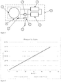
- Figure 1 there is shown an acoustic device in the form of a loudspeaker 6 and in close proximity an internal pressure sensor 1.
- the acoustic device and internal pressure sensor are contained within a pressure sealed and fluid tight container 8.
- the container is fluid impervious to a fluid such as water and is typically sealed to contain under pressure, a fluid such as air or a gas such as nitrogen especially in high humidity areas.
- the present invention deploys active pressure regulation.
- the internal pressure sensor 1 of the pressure regulator is coupled to a microprocessor or computer 3.
- the pressure regulator also includes a compressor 4 coupled to the acoustic device 6 and/or fluid tight container to remove fluid from the pressure tight (acoustic) chamber 8 as the water level increases, thus reducing the pressure in the acoustic chamber 8.
- the compressor is also coupled to the microprocessor 3.
- a gas storage container 5 receives gas from the compressor 4 and is connected to a valve 7 which is also connected to the microprocessor 3 and the acoustic chamber 8.
- the pressure regulator is contained with a fluid or water tight housing 9 to which is attached an external pressure sensor 2.
- the fluid or water tight housing is fluid impervious to a fluid such as water and may also be sealed to contain under pressure, a fluid such as air or a gas such as nitrogen.
- the external pressure sensor 2 is also coupled to the microprocessor 3.
- the microprocessor 3 receives information from the internal pressure sensor regarding the pressure inside, adjacent or in proximity to the acoustic device 6 and compares the same with information received from the external pressure sensor 2.
- the external and internal pressure sensors are disposed at the same depth within a tolerance of preferably +/- 0.01 m but tolerances of between 0.01 m and 0.5 m are envisaged.
- the external and internal pressure sensors may be disposed at different depths or outside of the depth tolerance and the microprocessor applies a calibration offset.
- the microprocessor 3 instructs the valve 7 to release gas from the gas storage container 5 to increase the gas pressure around the acoustic device 6. Conversely if the gas pressure is too great in the acoustic container 8, then the microprocessor instructs the valve 7 to activate and instructs the compressor 4 to enable gas to be stored in the gas storage container 5.
- the graph in Figure 2 illustrates how the pressure within the acoustic chamber varies with depth.
- the acoustic chamber is maintained at a constant pressure of anywhere between 0 Pa and 100 kPa, and most preferably 7.5 kPa above the hydrostatic water pressure across a depth range of 0 m to 100 m with a predetermined tolerance of pressure differential of between 1 Pa and 1 kPa and most preferably a pressure differential tolerance of 10 Pa.
- a feedback loop develops such that when the two pressures from the internal and external pressure sensors are within the predetermined tolerance, then the microprocessor instructs the valve to shut.
- the microprocessor 3 instructs the gas compressor to remove air from the acoustic chamber which is stored in the gas storage container 5.
- the microprocessor instructs the gas compressor to switch off.
- the present invention thus enables the gas pressure around the acoustic device to be increased and/or decreased to enable a more efficient acoustic response of the acoustic device irrespective of the depth at which the acoustic device is deployed.
- the pressure regulator As gas is compressed and stored in the gas storage container 5 and then released when required into the acoustic chamber, the pressure regulator is a closed system. Accordingly, replenishment is not required and the pressure regulator can be deployed at greater depths, difficult access areas and over a longer period of time than known hitherto; possibly up to 10 years.
- the present invention has far greater resolution than known previously e.g. 01.kPa over 30m and 0.3kPa over 100m.
- the present invention provides a closed active pressure regulation relatively quickly too which is most desirable in areas of dramatic changes in water depth.
- the microprocessor can react within 1 second of any pressure changes. Any increase in water depth and so raising of the internal pressure can be achieved much more quickly than decreasing the internal pressure.
- the present invention can achieve a rate of change of depth of 5m and so changes of 50 kPa per minute.
- the pressure regulator is supplied with a power source not shown.
- the acoustic device is shown within the watertight housing 9 of the pressure regulator.
- the watertight housing 9 may also need to be pressure sealed; particularly if the acoustic chamber 8 is omitted.
- references to the gas pressure in the acoustic container refer to gas pressure in the regulator housing.
- FIGS 3 and 4 depict alternative embodiments of the present invention.
- the acoustic device 6 or devices 6 within the respective acoustic chamber 8 is disposed outside of the waterproof housing 9.
- Figure 4 depicts the pressure regulator coupled to two acoustic devices.
- the same pressure regulator regulates the pressure within each pressure sealed and water tight container housing each containing a respective acoustic device.
- the acoustic devices may or may not be at the same depth and so require the same or different pressure.
- the pressure regulator may thus require two or more valves each coupled to a respective acoustic device to ensure optimum pressure regulation around the respective acoustic device.
- the present invention also encompasses two or more acoustic devices in the embodiments shown in figures 1 and 3 .
Landscapes
- Physics & Mathematics (AREA)
- Engineering & Computer Science (AREA)
- Acoustics & Sound (AREA)
- Signal Processing (AREA)
- Fluid Mechanics (AREA)
- General Physics & Mathematics (AREA)
- Automation & Control Theory (AREA)
- Control Of Fluid Pressure (AREA)
- Transducers For Ultrasonic Waves (AREA)
- Filling Or Discharging Of Gas Storage Vessels (AREA)
Abstract
Description
- The present invention relates to a pressure regulator and in particular to a closed active pressure regulator gas coupled to an acoustic device which is disposed in a fluid typically underwater.
- An acoustic device, such as a speaker, can be deployed underwater for many uses such as guiding fish, providing entertainment etc. However, as the depth of the acoustic device or underwater speaker increases, the external pressure increases proportionally. This pressure increase affects the acoustic response of the underwater speaker due to the external and internal differential pressure. As such the effectiveness of the speaker is reduced.
- In response to this problem, the internal pressure around the speaker system can be increased to reduce the pressure differential. It has been proposed that this could be achieved through a passive pressure regulation system by way of a pressurised, compressible external vessel. As the depth and pressure increases, the pressurised vessel is compressed and air is forced into the internal acoustic chamber.
- This method of passive gas pressure regulation is limited by the properties of the external vessel and can only be used at low depths. For example, when a speaker is disposed in a neoprene bag in salt water and depths of no more than 25 m, under long term use, i.e. periods of 9 months or so, the neoprene bag loses pressure and the gas therefore needs to be replaced.
- In response to increasing pressure at depth, alternative methods of passive pressure compensation have been developed: see for example the pressure compensators from Link: Fathom Systems Ltd. Typically, these systems operate at depths of greater than 1000 m where pressures exceed 1 x 10⁷ Pa. These systems are designed for use with electronic or hydraulic systems that can be submerged in hydraulic fluid due to the compressibility of air at these extreme depths limiting the pressure compensation systems working range. As the pressure increases with depth, the piston, which is exposed on one surface to the water, compresses the hydraulic fluid and increases pressure inside the electronics chamber. A disadvantage of a passive oil filled pressure compensation system is that they do not allow pressures to be regulated to high resolution e.g. tens of Pascals. In addition, the systems require a fluid filled enclosure for the electronic equipment.
- In JPH8-251687, there is disclosed a pressure equalising device for an underwater sound source. This pressure equaliser includes a diaphragm for generating the sound open to the water. A compression tank together with flow rate control valves and gas injection and gas exhaust lines are used to try and maintain the pressure to the other side of the diaphragm.
- Again such pressure equalising is limited due to poor sealing of the sound source such that a constant gas supply is needed and the equalisation occurs through varying the flow rate of the gas supplied or when exhausted, released to the sea. Accordingly, such a system is relatively crude and is unable to be used at greater depths with any degree of accuracy. In particular, the system is not a closed system, requiring constant recharging of the gas supply leading to its inability to be located at certain sites where constant recharging is not possible through operational difficulties such as depth or access.
- Thus, it is the aim of the present invention to mitigate such disadvantages of passive gas or oil pressure equalising systems
- The present invention thus relates to a pressure regulator comprising an internal pressure sensor, a valve, and a gas supply each coupled to a processor, at least said valve, gas supply and processor disposed within a fluid tight housing, said pressure regulator including an external pressure sensor coupled to the processor though the housing, whereby said pressure regulator is gas coupled to an acoustic device disposed underwater, said acoustic device contained within a pressure sealed and fluid tight container, said pressure regulator is a closed active system for removing gas from the container to the gas supply or supplying gas from the gas supply to the container, thereby regulating the pressure in the container.
- Embodiments of the present invention will now be described by way of example only and with reference to the accompanying drawings, of which:
-
Figure 1 is a schematic diagram of the present invention including an acoustic device; -
Figure 2 is a graph showing the maintenance of a set pressure differential between the acoustic chamber and the hydrostatic pressure at varying depths. -
Figure 3 is a schematic diagram of an alternative embodiment of the present invention coupled to an acoustic device; and -
Figure 4 is a schematic diagram of another alternative embodiment of the present invention coupled to two acoustic devices. - In
Figure 1 there is shown an acoustic device in the form of aloudspeaker 6 and in close proximity aninternal pressure sensor 1. The acoustic device and internal pressure sensor are contained within a pressure sealed and fluidtight container 8. The container is fluid impervious to a fluid such as water and is typically sealed to contain under pressure, a fluid such as air or a gas such as nitrogen especially in high humidity areas. - In contrast to the prior art example of the neoprene bag, the present invention deploys active pressure regulation. Accordingly, the
internal pressure sensor 1 of the pressure regulator is coupled to a microprocessor orcomputer 3. The pressure regulator also includes acompressor 4 coupled to theacoustic device 6 and/or fluid tight container to remove fluid from the pressure tight (acoustic)chamber 8 as the water level increases, thus reducing the pressure in theacoustic chamber 8. The compressor is also coupled to themicroprocessor 3. Agas storage container 5 receives gas from thecompressor 4 and is connected to avalve 7 which is also connected to themicroprocessor 3 and theacoustic chamber 8. - The pressure regulator is contained with a fluid or water
tight housing 9 to which is attached anexternal pressure sensor 2. The fluid or water tight housing is fluid impervious to a fluid such as water and may also be sealed to contain under pressure, a fluid such as air or a gas such as nitrogen. Theexternal pressure sensor 2 is also coupled to themicroprocessor 3. - The coupling of the various elements to the pressure sealed and fluid tight areas is effected by way of seals known to persons skilled in the art, e.g. o rings, dual rubber o rings and/or threaded connections.
- In operation, the
microprocessor 3 receives information from the internal pressure sensor regarding the pressure inside, adjacent or in proximity to theacoustic device 6 and compares the same with information received from theexternal pressure sensor 2. Needless to say, the external and internal pressure sensors are disposed at the same depth within a tolerance of preferably +/- 0.01 m but tolerances of between 0.01 m and 0.5 m are envisaged. - Alternatively, the external and internal pressure sensors may be disposed at different depths or outside of the depth tolerance and the microprocessor applies a calibration offset.
- If the pressure difference between the external and internal pressure sensors exceeds a predetermined tolerance, then the
microprocessor 3 instructs thevalve 7 to release gas from thegas storage container 5 to increase the gas pressure around theacoustic device 6. Conversely if the gas pressure is too great in theacoustic container 8, then the microprocessor instructs thevalve 7 to activate and instructs thecompressor 4 to enable gas to be stored in thegas storage container 5. - The graph in
Figure 2 illustrates how the pressure within the acoustic chamber varies with depth. Preferably, the acoustic chamber is maintained at a constant pressure of anywhere between 0 Pa and 100 kPa, and most preferably 7.5 kPa above the hydrostatic water pressure across a depth range of 0 m to 100 m with a predetermined tolerance of pressure differential of between 1 Pa and 1 kPa and most preferably a pressure differential tolerance of 10 Pa. - A feedback loop develops such that when the two pressures from the internal and external pressure sensors are within the predetermined tolerance, then the microprocessor instructs the valve to shut.
- As is the case with tidal water levels and varying river water heights, when the water level drops, the pressure in the acoustic chamber will need to decrease to maintain the predetermined pressure differential. Therefore, the
microprocessor 3 instructs the gas compressor to remove air from the acoustic chamber which is stored in thegas storage container 5. When the two pressures from the internal and external pressure sensors are within the predetermined tolerance, then the microprocessor instructs the gas compressor to switch off. - The present invention thus enables the gas pressure around the acoustic device to be increased and/or decreased to enable a more efficient acoustic response of the acoustic device irrespective of the depth at which the acoustic device is deployed.
- As gas is compressed and stored in the
gas storage container 5 and then released when required into the acoustic chamber, the pressure regulator is a closed system. Accordingly, replenishment is not required and the pressure regulator can be deployed at greater depths, difficult access areas and over a longer period of time than known hitherto; possibly up to 10 years. In addition, the present invention has far greater resolution than known previously e.g. 01.kPa over 30m and 0.3kPa over 100m. - The present invention provides a closed active pressure regulation relatively quickly too which is most desirable in areas of dramatic changes in water depth. The microprocessor can react within 1 second of any pressure changes. Any increase in water depth and so raising of the internal pressure can be achieved much more quickly than decreasing the internal pressure. For example, the present invention can achieve a rate of change of depth of 5m and so changes of 50 kPa per minute.
- The pressure regulator is supplied with a power source not shown.
- In
Figure 1 , the acoustic device is shown within thewatertight housing 9 of the pressure regulator. Thus, thewatertight housing 9 may also need to be pressure sealed; particularly if theacoustic chamber 8 is omitted. In which case, references to the gas pressure in the acoustic container refer to gas pressure in the regulator housing. -
Figures 3 and 4 depict alternative embodiments of the present invention. In these two instances, theacoustic device 6 ordevices 6 within the respectiveacoustic chamber 8 is disposed outside of thewaterproof housing 9. -
Figure 4 depicts the pressure regulator coupled to two acoustic devices. The same pressure regulator regulates the pressure within each pressure sealed and water tight container housing each containing a respective acoustic device. The acoustic devices may or may not be at the same depth and so require the same or different pressure. The pressure regulator may thus require two or more valves each coupled to a respective acoustic device to ensure optimum pressure regulation around the respective acoustic device. Needless to say, the present invention also encompasses two or more acoustic devices in the embodiments shown infigures 1 and3 .
Claims (7)
- A pressure regulator comprising an internal pressure sensor (1), a valve (7), and a gas supply (4,5) each coupled to a processor (3), at least said valve, gas supply and processor disposed within a fluid tight housing (9), said pressure regulator including an external pressure sensor (2) coupled to the processor though the housing, whereby said pressure regulator is gas coupled to an acoustic device (6) disposed underwater, said acoustic device contained within a pressure sealed and fluid tight container (8), characterised in that said pressure regulator is a closed active system for removing gas from the container to the gas supply or supplying the gas from the gas supply to the container thereby regulating the pressure in the container.
- A pressure regulator as claimed in claim 1, in which said internal and external pressure sensors are disposed at the same depth.
- A pressure regulator as claimed in claim 1, in which said internal and external pressure sensors are not disposed at the same depth and the microprocessor applies a calibration offset.
- A pressure regulator as claimed in any one of the preceding claims in which said fluid tight housing for the pressure regulator is also pressure sealed so forms the pressure sealed and fluid tight container of the acoustic device.
- A pressure regulator as claimed in any one of the preceding claims, in which said gas supply comprises a compressor (4) and a storage chamber (5) with said compressor coupled to the processor and the storage chamber coupled to the valve.
- A pressure regulator as claimed in any one of the preceding claims, in which there is more than one acoustic device.
- A pressure regulator as claimed in claim 6, in which each acoustic device is disposed at a different depth.
Priority Applications (1)
| Application Number | Priority Date | Filing Date | Title |
|---|---|---|---|
| PL19020616T PL3651475T3 (en) | 2018-11-07 | 2019-11-05 | A pressure regulator for hydrophone |
Applications Claiming Priority (1)
| Application Number | Priority Date | Filing Date | Title |
|---|---|---|---|
| GB1818150.3A GB2578765A (en) | 2018-11-07 | 2018-11-07 | A pressure regulator |
Publications (2)
| Publication Number | Publication Date |
|---|---|
| EP3651475A1 true EP3651475A1 (en) | 2020-05-13 |
| EP3651475B1 EP3651475B1 (en) | 2022-01-26 |
Family
ID=64655461
Family Applications (1)
| Application Number | Title | Priority Date | Filing Date |
|---|---|---|---|
| EP19020616.9A Active EP3651475B1 (en) | 2018-11-07 | 2019-11-05 | A pressure regulator for hydrophone |
Country Status (9)
| Country | Link |
|---|---|
| US (1) | US10999674B2 (en) |
| EP (1) | EP3651475B1 (en) |
| AU (1) | AU2019261721B2 (en) |
| CA (1) | CA3060973A1 (en) |
| DK (1) | DK3651475T3 (en) |
| ES (1) | ES2911376T3 (en) |
| GB (2) | GB2578765A (en) |
| PL (1) | PL3651475T3 (en) |
| PT (1) | PT3651475T (en) |
Families Citing this family (1)
| Publication number | Priority date | Publication date | Assignee | Title |
|---|---|---|---|---|
| US11417099B1 (en) | 2021-11-08 | 2022-08-16 | 9219-1568 Quebec Inc. | System and method for digital fingerprinting of media content |
Citations (4)
| Publication number | Priority date | Publication date | Assignee | Title |
|---|---|---|---|---|
| DE1216371B (en) * | 1963-06-28 | 1966-05-12 | Bendix Corp | Underwater speakers |
| US5103432A (en) * | 1991-01-10 | 1992-04-07 | The United States Of America As Represented By The Secretary Of The Navy | Expendable sound source |
| US5140560A (en) * | 1988-07-29 | 1992-08-18 | The United States Of America As Represented By The Secretary Of The Navy | Pressure compensated transducer system with constrained diaphragm |
| JPH08251687A (en) * | 1995-03-10 | 1996-09-27 | Ishikawajima Harima Heavy Ind Co Ltd | Pressure equalizer for underwater sound source |
Family Cites Families (7)
| Publication number | Priority date | Publication date | Assignee | Title |
|---|---|---|---|---|
| JPS5829293A (en) * | 1981-08-14 | 1983-02-21 | Hitachi Ltd | underwater wave transmitter |
| JPS6180996A (en) * | 1984-09-28 | 1986-04-24 | Hitachi Ltd | underwater transmitter |
| CH684965A5 (en) * | 1991-10-18 | 1995-02-15 | Linde Ag | Method and apparatus for increasing the efficiency of compression devices. |
| US5815589A (en) * | 1997-02-18 | 1998-09-29 | Wainwright; Charles E. | Push-pull transmission line loudspeaker |
| US10097959B2 (en) * | 2016-07-13 | 2018-10-09 | Play Impossible Corporation | Capturing smart playable device and gestures |
| US11706563B2 (en) * | 2016-09-16 | 2023-07-18 | Gopro, Inc. | Submersible speaker system with a compressible spacer |
| CN107682780B (en) * | 2017-09-07 | 2019-08-13 | 江山显进机电科技服务有限公司 | Pressure sensitive trigger sounder for underwater use |
-
2018
- 2018-11-07 GB GB1818150.3A patent/GB2578765A/en not_active Withdrawn
-
2019
- 2019-11-05 US US16/674,322 patent/US10999674B2/en active Active
- 2019-11-05 DK DK19020616.9T patent/DK3651475T3/en active
- 2019-11-05 EP EP19020616.9A patent/EP3651475B1/en active Active
- 2019-11-05 PT PT190206169T patent/PT3651475T/en unknown
- 2019-11-05 PL PL19020616T patent/PL3651475T3/en unknown
- 2019-11-05 ES ES19020616T patent/ES2911376T3/en active Active
- 2019-11-05 GB GB1916088.6A patent/GB2580497A/en not_active Withdrawn
- 2019-11-06 AU AU2019261721A patent/AU2019261721B2/en active Active
- 2019-11-06 CA CA3060973A patent/CA3060973A1/en active Pending
Patent Citations (4)
| Publication number | Priority date | Publication date | Assignee | Title |
|---|---|---|---|---|
| DE1216371B (en) * | 1963-06-28 | 1966-05-12 | Bendix Corp | Underwater speakers |
| US5140560A (en) * | 1988-07-29 | 1992-08-18 | The United States Of America As Represented By The Secretary Of The Navy | Pressure compensated transducer system with constrained diaphragm |
| US5103432A (en) * | 1991-01-10 | 1992-04-07 | The United States Of America As Represented By The Secretary Of The Navy | Expendable sound source |
| JPH08251687A (en) * | 1995-03-10 | 1996-09-27 | Ishikawajima Harima Heavy Ind Co Ltd | Pressure equalizer for underwater sound source |
Also Published As
| Publication number | Publication date |
|---|---|
| DK3651475T3 (en) | 2022-04-11 |
| EP3651475B1 (en) | 2022-01-26 |
| GB201818150D0 (en) | 2018-12-19 |
| GB201916088D0 (en) | 2019-12-18 |
| PL3651475T3 (en) | 2022-05-23 |
| CA3060973A1 (en) | 2020-05-07 |
| AU2019261721A1 (en) | 2020-05-21 |
| US20200145750A1 (en) | 2020-05-07 |
| US10999674B2 (en) | 2021-05-04 |
| GB2578765A (en) | 2020-05-27 |
| PT3651475T (en) | 2022-04-06 |
| AU2019261721B2 (en) | 2024-11-21 |
| GB2580497A (en) | 2020-07-22 |
| ES2911376T3 (en) | 2022-05-19 |
Similar Documents
| Publication | Publication Date | Title |
|---|---|---|
| US9097267B2 (en) | Pressure intensifier system for subsea running tools | |
| CN110195732B (en) | A pressure load simulation system suitable for deep-sea equipment hydraulic system and its application | |
| US7424917B2 (en) | Subsea pressure compensation system | |
| US8353351B2 (en) | System and method for regulating pressure within a well annulus | |
| EP2959319A2 (en) | Method and system for pneumatic control for vibrator source element | |
| AU2019261721B2 (en) | A pressure regulator | |
| BR112015017644B1 (en) | SUBSEA WAVE-EFFECT PASSIVE COMPENSATION AND METHOD OF PROVIDING VARIABLE COMPENSATION FOR SUCH COMPENSATION | |
| RU2555927C2 (en) | Sealing system with pressure compensation for rotation of movement shaft | |
| CA2294978A1 (en) | Depth control device | |
| NO20141416A1 (en) | Method and system for regulating fluid | |
| JP2020131933A (en) | Flotation adjusting device and underwater traveling body | |
| CN119878635B (en) | Integrated deep sea hydraulic control valve box | |
| CN110308734A (en) | Underwater robot navigation state adjustment liquid tank system, underwater robot and control method | |
| GB2534226A (en) | Rotary shaft sealing system | |
| US20140174552A1 (en) | Subsea pressure regulator | |
| WO2017210931A1 (en) | Built-in pressure compensation system | |
| US20210140250A1 (en) | Disruptive coupling systems and methods for subsea systems | |
| CA2698916C (en) | Subsea valve | |
| JP2005210152A (en) | Pressure compensation apparatus and the same for underwater transmitter | |
| RU2272099C1 (en) | Method for hydraulic structure opening sealing | |
| CN121734638A (en) | Buoyancy adjusting device for unmanned underwater vehicle and underwater vehicle |
Legal Events
| Date | Code | Title | Description |
|---|---|---|---|
| PUAI | Public reference made under article 153(3) epc to a published international application that has entered the european phase |
Free format text: ORIGINAL CODE: 0009012 |
|
| STAA | Information on the status of an ep patent application or granted ep patent |
Free format text: STATUS: THE APPLICATION HAS BEEN PUBLISHED |
|
| AK | Designated contracting states |
Kind code of ref document: A1 Designated state(s): AL AT BE BG CH CY CZ DE DK EE ES FI FR GB GR HR HU IE IS IT LI LT LU LV MC MK MT NL NO PL PT RO RS SE SI SK SM TR |
|
| AX | Request for extension of the european patent |
Extension state: BA ME |
|
| STAA | Information on the status of an ep patent application or granted ep patent |
Free format text: STATUS: REQUEST FOR EXAMINATION WAS MADE |
|
| 17P | Request for examination filed |
Effective date: 20201109 |
|
| GRAP | Despatch of communication of intention to grant a patent |
Free format text: ORIGINAL CODE: EPIDOSNIGR1 |
|
| STAA | Information on the status of an ep patent application or granted ep patent |
Free format text: STATUS: GRANT OF PATENT IS INTENDED |
|
| INTG | Intention to grant announced |
Effective date: 20211026 |
|
| GRAS | Grant fee paid |
Free format text: ORIGINAL CODE: EPIDOSNIGR3 |
|
| GRAA | (expected) grant |
Free format text: ORIGINAL CODE: 0009210 |
|
| STAA | Information on the status of an ep patent application or granted ep patent |
Free format text: STATUS: THE PATENT HAS BEEN GRANTED |
|
| AK | Designated contracting states |
Kind code of ref document: B1 Designated state(s): AL AT BE BG CH CY CZ DE DK EE ES FI FR GB GR HR HU IE IS IT LI LT LU LV MC MK MT NL NO PL PT RO RS SE SI SK SM TR |
|
| REG | Reference to a national code |
Ref country code: GB Ref legal event code: FG4D |
|
| REG | Reference to a national code |
Ref country code: CH Ref legal event code: EP |
|
| REG | Reference to a national code |
Ref country code: AT Ref legal event code: REF Ref document number: 1466214 Country of ref document: AT Kind code of ref document: T Effective date: 20220215 |
|
| REG | Reference to a national code |
Ref country code: IE Ref legal event code: FG4D |
|
| REG | Reference to a national code |
Ref country code: DE Ref legal event code: R096 Ref document number: 602019011113 Country of ref document: DE |
|
| REG | Reference to a national code |
Ref country code: PT Ref legal event code: SC4A Ref document number: 3651475 Country of ref document: PT Date of ref document: 20220406 Kind code of ref document: T Free format text: AVAILABILITY OF NATIONAL TRANSLATION Effective date: 20220331 |
|
| REG | Reference to a national code |
Ref country code: DK Ref legal event code: T3 Effective date: 20220407 |
|
| REG | Reference to a national code |
Ref country code: SE Ref legal event code: TRGR |
|
| REG | Reference to a national code |
Ref country code: FI Ref legal event code: FGE |
|
| REG | Reference to a national code |
Ref country code: NO Ref legal event code: T2 Effective date: 20220126 |
|
| REG | Reference to a national code |
Ref country code: NL Ref legal event code: FP |
|
| REG | Reference to a national code |
Ref country code: ES Ref legal event code: FG2A Ref document number: 2911376 Country of ref document: ES Kind code of ref document: T3 Effective date: 20220519 |
|
| REG | Reference to a national code |
Ref country code: LT Ref legal event code: MG9D |
|
| REG | Reference to a national code |
Ref country code: GR Ref legal event code: EP Ref document number: 20220400835 Country of ref document: GR Effective date: 20220509 |
|
| REG | Reference to a national code |
Ref country code: AT Ref legal event code: MK05 Ref document number: 1466214 Country of ref document: AT Kind code of ref document: T Effective date: 20220126 |
|
| PG25 | Lapsed in a contracting state [announced via postgrant information from national office to epo] |
Ref country code: RS Free format text: LAPSE BECAUSE OF FAILURE TO SUBMIT A TRANSLATION OF THE DESCRIPTION OR TO PAY THE FEE WITHIN THE PRESCRIBED TIME-LIMIT Effective date: 20220126 Ref country code: LT Free format text: LAPSE BECAUSE OF FAILURE TO SUBMIT A TRANSLATION OF THE DESCRIPTION OR TO PAY THE FEE WITHIN THE PRESCRIBED TIME-LIMIT Effective date: 20220126 Ref country code: HR Free format text: LAPSE BECAUSE OF FAILURE TO SUBMIT A TRANSLATION OF THE DESCRIPTION OR TO PAY THE FEE WITHIN THE PRESCRIBED TIME-LIMIT Effective date: 20220126 Ref country code: BG Free format text: LAPSE BECAUSE OF FAILURE TO SUBMIT A TRANSLATION OF THE DESCRIPTION OR TO PAY THE FEE WITHIN THE PRESCRIBED TIME-LIMIT Effective date: 20220426 |
|
| PG25 | Lapsed in a contracting state [announced via postgrant information from national office to epo] |
Ref country code: LV Free format text: LAPSE BECAUSE OF FAILURE TO SUBMIT A TRANSLATION OF THE DESCRIPTION OR TO PAY THE FEE WITHIN THE PRESCRIBED TIME-LIMIT Effective date: 20220126 Ref country code: AT Free format text: LAPSE BECAUSE OF FAILURE TO SUBMIT A TRANSLATION OF THE DESCRIPTION OR TO PAY THE FEE WITHIN THE PRESCRIBED TIME-LIMIT Effective date: 20220126 |
|
| PG25 | Lapsed in a contracting state [announced via postgrant information from national office to epo] |
Ref country code: IS Free format text: LAPSE BECAUSE OF FAILURE TO SUBMIT A TRANSLATION OF THE DESCRIPTION OR TO PAY THE FEE WITHIN THE PRESCRIBED TIME-LIMIT Effective date: 20220526 |
|
| REG | Reference to a national code |
Ref country code: DE Ref legal event code: R097 Ref document number: 602019011113 Country of ref document: DE |
|
| PG25 | Lapsed in a contracting state [announced via postgrant information from national office to epo] |
Ref country code: SM Free format text: LAPSE BECAUSE OF FAILURE TO SUBMIT A TRANSLATION OF THE DESCRIPTION OR TO PAY THE FEE WITHIN THE PRESCRIBED TIME-LIMIT Effective date: 20220126 Ref country code: SK Free format text: LAPSE BECAUSE OF FAILURE TO SUBMIT A TRANSLATION OF THE DESCRIPTION OR TO PAY THE FEE WITHIN THE PRESCRIBED TIME-LIMIT Effective date: 20220126 Ref country code: RO Free format text: LAPSE BECAUSE OF FAILURE TO SUBMIT A TRANSLATION OF THE DESCRIPTION OR TO PAY THE FEE WITHIN THE PRESCRIBED TIME-LIMIT Effective date: 20220126 Ref country code: EE Free format text: LAPSE BECAUSE OF FAILURE TO SUBMIT A TRANSLATION OF THE DESCRIPTION OR TO PAY THE FEE WITHIN THE PRESCRIBED TIME-LIMIT Effective date: 20220126 Ref country code: CZ Free format text: LAPSE BECAUSE OF FAILURE TO SUBMIT A TRANSLATION OF THE DESCRIPTION OR TO PAY THE FEE WITHIN THE PRESCRIBED TIME-LIMIT Effective date: 20220126 |
|
| PG25 | Lapsed in a contracting state [announced via postgrant information from national office to epo] |
Ref country code: AL Free format text: LAPSE BECAUSE OF FAILURE TO SUBMIT A TRANSLATION OF THE DESCRIPTION OR TO PAY THE FEE WITHIN THE PRESCRIBED TIME-LIMIT Effective date: 20220126 |
|
| PLBE | No opposition filed within time limit |
Free format text: ORIGINAL CODE: 0009261 |
|
| STAA | Information on the status of an ep patent application or granted ep patent |
Free format text: STATUS: NO OPPOSITION FILED WITHIN TIME LIMIT |
|
| 26N | No opposition filed |
Effective date: 20221027 |
|
| PG25 | Lapsed in a contracting state [announced via postgrant information from national office to epo] |
Ref country code: SI Free format text: LAPSE BECAUSE OF FAILURE TO SUBMIT A TRANSLATION OF THE DESCRIPTION OR TO PAY THE FEE WITHIN THE PRESCRIBED TIME-LIMIT Effective date: 20220126 |
|
| PG25 | Lapsed in a contracting state [announced via postgrant information from national office to epo] |
Ref country code: MC Free format text: LAPSE BECAUSE OF FAILURE TO SUBMIT A TRANSLATION OF THE DESCRIPTION OR TO PAY THE FEE WITHIN THE PRESCRIBED TIME-LIMIT Effective date: 20220126 |
|
| REG | Reference to a national code |
Ref country code: CH Ref legal event code: PL |
|
| PG25 | Lapsed in a contracting state [announced via postgrant information from national office to epo] |
Ref country code: LI Free format text: LAPSE BECAUSE OF NON-PAYMENT OF DUE FEES Effective date: 20221130 Ref country code: CH Free format text: LAPSE BECAUSE OF NON-PAYMENT OF DUE FEES Effective date: 20221130 |
|
| PG25 | Lapsed in a contracting state [announced via postgrant information from national office to epo] |
Ref country code: LU Free format text: LAPSE BECAUSE OF NON-PAYMENT OF DUE FEES Effective date: 20221105 |
|
| P01 | Opt-out of the competence of the unified patent court (upc) registered |
Effective date: 20240109 |
|
| PG25 | Lapsed in a contracting state [announced via postgrant information from national office to epo] |
Ref country code: HU Free format text: LAPSE BECAUSE OF FAILURE TO SUBMIT A TRANSLATION OF THE DESCRIPTION OR TO PAY THE FEE WITHIN THE PRESCRIBED TIME-LIMIT; INVALID AB INITIO Effective date: 20191105 |
|
| PG25 | Lapsed in a contracting state [announced via postgrant information from national office to epo] |
Ref country code: CY Free format text: LAPSE BECAUSE OF FAILURE TO SUBMIT A TRANSLATION OF THE DESCRIPTION OR TO PAY THE FEE WITHIN THE PRESCRIBED TIME-LIMIT Effective date: 20220126 |
|
| PG25 | Lapsed in a contracting state [announced via postgrant information from national office to epo] |
Ref country code: MK Free format text: LAPSE BECAUSE OF FAILURE TO SUBMIT A TRANSLATION OF THE DESCRIPTION OR TO PAY THE FEE WITHIN THE PRESCRIBED TIME-LIMIT Effective date: 20220126 |
|
| PG25 | Lapsed in a contracting state [announced via postgrant information from national office to epo] |
Ref country code: TR Free format text: LAPSE BECAUSE OF FAILURE TO SUBMIT A TRANSLATION OF THE DESCRIPTION OR TO PAY THE FEE WITHIN THE PRESCRIBED TIME-LIMIT Effective date: 20220126 |
|
| PG25 | Lapsed in a contracting state [announced via postgrant information from national office to epo] |
Ref country code: MT Free format text: LAPSE BECAUSE OF FAILURE TO SUBMIT A TRANSLATION OF THE DESCRIPTION OR TO PAY THE FEE WITHIN THE PRESCRIBED TIME-LIMIT Effective date: 20220126 |
|
| PGFP | Annual fee paid to national office [announced via postgrant information from national office to epo] |
Ref country code: GB Payment date: 20250901 Year of fee payment: 7 |
|
| PGFP | Annual fee paid to national office [announced via postgrant information from national office to epo] |
Ref country code: PT Payment date: 20251024 Year of fee payment: 7 |
|
| PGFP | Annual fee paid to national office [announced via postgrant information from national office to epo] |
Ref country code: NL Payment date: 20251126 Year of fee payment: 7 |
|
| PGFP | Annual fee paid to national office [announced via postgrant information from national office to epo] |
Ref country code: DE Payment date: 20251128 Year of fee payment: 7 |
|
| PGFP | Annual fee paid to national office [announced via postgrant information from national office to epo] |
Ref country code: NO Payment date: 20251128 Year of fee payment: 7 |
|
| PGFP | Annual fee paid to national office [announced via postgrant information from national office to epo] |
Ref country code: FI Payment date: 20251125 Year of fee payment: 7 Ref country code: DK Payment date: 20251125 Year of fee payment: 7 Ref country code: IT Payment date: 20251119 Year of fee payment: 7 |
|
| PGFP | Annual fee paid to national office [announced via postgrant information from national office to epo] |
Ref country code: FR Payment date: 20251125 Year of fee payment: 7 |
|
| PGFP | Annual fee paid to national office [announced via postgrant information from national office to epo] |
Ref country code: GR Payment date: 20251126 Year of fee payment: 7 Ref country code: BE Payment date: 20251127 Year of fee payment: 7 |
|
| PGFP | Annual fee paid to national office [announced via postgrant information from national office to epo] |
Ref country code: SE Payment date: 20251127 Year of fee payment: 7 |
|
| PGFP | Annual fee paid to national office [announced via postgrant information from national office to epo] |
Ref country code: IE Payment date: 20251127 Year of fee payment: 7 |
|
| PGFP | Annual fee paid to national office [announced via postgrant information from national office to epo] |
Ref country code: PL Payment date: 20251021 Year of fee payment: 7 |
|
| PGFP | Annual fee paid to national office [announced via postgrant information from national office to epo] |
Ref country code: ES Payment date: 20251201 Year of fee payment: 7 |