EP3651397A1 - An der übertragung von signalen beteiligtes benutzergerät und netzwerkknoten - Google Patents
An der übertragung von signalen beteiligtes benutzergerät und netzwerkknoten Download PDFInfo
- Publication number
- EP3651397A1 EP3651397A1 EP18205761.2A EP18205761A EP3651397A1 EP 3651397 A1 EP3651397 A1 EP 3651397A1 EP 18205761 A EP18205761 A EP 18205761A EP 3651397 A1 EP3651397 A1 EP 3651397A1
- Authority
- EP
- European Patent Office
- Prior art keywords
- rnti
- transmissions
- trp
- receptions
- dci
- Prior art date
- Legal status (The legal status is an assumption and is not a legal conclusion. Google has not performed a legal analysis and makes no representation as to the accuracy of the status listed.)
- Withdrawn
Links
Images


Classifications
-
- H—ELECTRICITY
- H04—ELECTRIC COMMUNICATION TECHNIQUE
- H04W—WIRELESS COMMUNICATION NETWORKS
- H04W72/00—Local resource management
- H04W72/20—Control channels or signalling for resource management
- H04W72/23—Control channels or signalling for resource management in the downlink direction of a wireless link, i.e. towards a terminal
-
- H—ELECTRICITY
- H04—ELECTRIC COMMUNICATION TECHNIQUE
- H04L—TRANSMISSION OF DIGITAL INFORMATION, e.g. TELEGRAPHIC COMMUNICATION
- H04L5/00—Arrangements affording multiple use of the transmission path
- H04L5/003—Arrangements for allocating sub-channels of the transmission path
- H04L5/0032—Distributed allocation, i.e. involving a plurality of allocating devices, each making partial allocation
- H04L5/0035—Resource allocation in a cooperative multipoint environment
-
- H—ELECTRICITY
- H04—ELECTRIC COMMUNICATION TECHNIQUE
- H04L—TRANSMISSION OF DIGITAL INFORMATION, e.g. TELEGRAPHIC COMMUNICATION
- H04L5/00—Arrangements affording multiple use of the transmission path
- H04L5/0001—Arrangements for dividing the transmission path
- H04L5/0014—Three-dimensional division
- H04L5/0023—Time-frequency-space
-
- H—ELECTRICITY
- H04—ELECTRIC COMMUNICATION TECHNIQUE
- H04L—TRANSMISSION OF DIGITAL INFORMATION, e.g. TELEGRAPHIC COMMUNICATION
- H04L5/00—Arrangements affording multiple use of the transmission path
- H04L5/003—Arrangements for allocating sub-channels of the transmission path
- H04L5/0048—Allocation of pilot signals, i.e. of signals known to the receiver
-
- H—ELECTRICITY
- H04—ELECTRIC COMMUNICATION TECHNIQUE
- H04L—TRANSMISSION OF DIGITAL INFORMATION, e.g. TELEGRAPHIC COMMUNICATION
- H04L5/00—Arrangements affording multiple use of the transmission path
- H04L5/0091—Signaling for the administration of the divided path
- H04L5/0094—Indication of how sub-channels of the path are allocated
-
- H—ELECTRICITY
- H04—ELECTRIC COMMUNICATION TECHNIQUE
- H04L—TRANSMISSION OF DIGITAL INFORMATION, e.g. TELEGRAPHIC COMMUNICATION
- H04L69/00—Network arrangements, protocols or services independent of the application payload and not provided for in the other groups of this subclass
- H04L69/30—Definitions, standards or architectural aspects of layered protocol stacks
- H04L69/32—Architecture of open systems interconnection [OSI] 7-layer type protocol stacks, e.g. the interfaces between the data link level and the physical level
- H04L69/322—Intralayer communication protocols among peer entities or protocol data unit [PDU] definitions
- H04L69/324—Intralayer communication protocols among peer entities or protocol data unit [PDU] definitions in the data link layer [OSI layer 2], e.g. HDLC
-
- H—ELECTRICITY
- H04—ELECTRIC COMMUNICATION TECHNIQUE
- H04W—WIRELESS COMMUNICATION NETWORKS
- H04W76/00—Connection management
- H04W76/20—Manipulation of established connections
- H04W76/27—Transitions between radio resource control [RRC] states
-
- H—ELECTRICITY
- H04—ELECTRIC COMMUNICATION TECHNIQUE
- H04B—TRANSMISSION
- H04B7/00—Radio transmission systems, i.e. using radiation field
- H04B7/02—Diversity systems; Multi-antenna system, i.e. transmission or reception using multiple antennas
- H04B7/022—Site diversity; Macro-diversity
- H04B7/024—Co-operative use of antennas of several sites, e.g. in co-ordinated multipoint or co-operative multiple-input multiple-output [MIMO] systems
-
- H—ELECTRICITY
- H04—ELECTRIC COMMUNICATION TECHNIQUE
- H04L—TRANSMISSION OF DIGITAL INFORMATION, e.g. TELEGRAPHIC COMMUNICATION
- H04L5/00—Arrangements affording multiple use of the transmission path
- H04L5/003—Arrangements for allocating sub-channels of the transmission path
- H04L5/0048—Allocation of pilot signals, i.e. of signals known to the receiver
- H04L5/0051—Allocation of pilot signals, i.e. of signals known to the receiver of dedicated pilots, i.e. pilots destined for a single user or terminal
-
- H—ELECTRICITY
- H04—ELECTRIC COMMUNICATION TECHNIQUE
- H04L—TRANSMISSION OF DIGITAL INFORMATION, e.g. TELEGRAPHIC COMMUNICATION
- H04L5/00—Arrangements affording multiple use of the transmission path
- H04L5/003—Arrangements for allocating sub-channels of the transmission path
- H04L5/0053—Allocation of signaling, i.e. of overhead other than pilot signals
Definitions
- the present disclosure relates to transmission and reception of signals in a communication system.
- the present disclosure relates to methods and apparatuses for such transmission and reception.
- the 3rd Generation Partnership Project (3GPP) works at technical specifications for the next generation cellular technology, which is also called fifth generation (5G) including "New Radio" (NR) radio access technology (RAT), which operates in frequency ranges up to 100 GHz.
- 5G Fifth Generation
- NR radio access technology
- the NR is a follower of the technology represented by Long Term Evolution (LTE) and LTE Advanced (LTE-A).
- One non-limiting and exemplary embodiment facilitates physical downlink control channel (PDCCH) signaling for multi-TRP (transmission and reception point) communication.
- PDCCH physical downlink control channel
- the techniques disclosed herein feature a user equipment (UE) comprising a transceiver which, in operation, receives, on a physical downlink control channel, PDCCH, downlink control information, DCI, for scheduling a plurality of transmissions or receptions between the UE and a plurality of transmission and reception points, TRPs, on a plurality of channels, the DCI including one or more indicators indicating one or more respective transmission parameters, and circuitry which, in operation, obtains, based on the one or more indicators and on a configuration, a plurality of values respectively of the one or more transmission parameters, wherein the transceiver, in operation, performs the plurality of transmissions or receptions using a respective one of the plurality of values of the one or more transmission parameters for each of the plurality of transmissions or receptions.
- UE user equipment
- Fig. 1 shows an exemplary example of a communication system including a base station and a terminal and a core network.
- Such communication system may be a 3GPP system such as NR and/or LTE and/or UMTS.
- the base station may be a gNB (gNodeB, e.g. an NR gNB) or an eNB (eNodeB, e.g. an LTE gNB).
- gNB gNodeB
- eNodeB e.g. an LTE gNB
- the present disclosure is not limited to these 3GPP systems or to any other systems. Even though the embodiments and exemplary implementations are described using some terminology of 3GPP systems, the present disclosure is also applicable to any other communication systems, and in particular in any cellular, wireless and/or mobile systems.
- the NR is planned to facilitate providing a single technical framework addressing several usage scenarios, requirements and deployment scenarios defined including, for instance, enhanced mobile broadband (eMBB), ultra-reliable low-latency communications (URLLC), massive machine type communication (mMTC), and the like.
- eMBB deployment scenarios may include indoor hotspot, dense urban, rural, urban macro and high speed
- URLLC deployment scenarios may include industrial control systems, mobile health care (remote monitoring, diagnosis and treatment), real time control of vehicles, wide area monitoring and control systems for smart grids
- mMTC may include scenarios with large number of devices with non-time critical data transfers such as smart wearables and sensor networks.
- the Physical layer is based on time-frequency resources (such as Orthogonal Frequency Division Multiplexing, OFDM, similar to LTE) and may support multiple antenna operation.
- OFDM Orthogonal Frequency Division Multiplexing
- a terminal is referred to in the LTE and NR as a user equipment (UE).
- UE user equipment
- This may be a mobile device such as a wireless phone, smartphone, tablet computer, or an USB (universal serial bus) stick with the functionality of a user equipment.
- the term mobile device is not limited thereto, in general, a relay may also have functionality of such mobile device, and a mobile device may also work as a relay.
- a base station is a network node, e.g. forming a part of the network for providing services to terminals.
- a base station is a network node, which provides wireless access to terminals.
- the physical layer in NR may provide multi-antenna operation such as MIMO (multiple input, multiple output) which may, for instance, include the use of plural or multiple transmission and reception points (multi-TRP).
- MIMO multiple input, multiple output
- multi-TRP transmission and reception points
- a user equipment may receive data from plural TRPs (transmission and reception points), wherein the plural-TRPs may be controlled by the same or different network nodes.
- TRPs transmission and reception points
- CoMP coordinated multi-point transmission
- multi-TRP may further be enhanced in accordance with a new work item on NR MIMO (cf. RP-182067, 'Revised WID (work item description): Enhancements on MIMO for NR', Samsung, 3GPP TSG RAN (Technical Specification Group Radio Access Network) Meeting #81, Gold Coast, Australia, Sept 10 - 13, 2018 ).
- the present disclosure deals with multi-TRP communication and proposes techniques related for instance to single PDCCH (physical downlink control channel) transmission, where a single PDCCH is used to schedule data or control channels such as PDSCH (physical downlink shared channel), PUSCH (physical uplink shared channel), or PUCCH (physical uplink control channel) for multiple TRPs.
- Some of the discussed techniques are related to DMRS port indication table for mapping demodulation reference signals (DMRS) ports to multiple layers for transmission on multiple TRPs and transmission configuration indication (TCI) state signaling for multiple TRPs. Signaling modifications related to both DMRS port indication and TCI state via single PDCCH for multi-TRP transmission/reception of data channels are discussed.
- DMRS demodulation reference signals
- TCI transmission configuration indication
- Multi-TRP involves transmission/reception from/to multiple points that are either connected to each other via ideal or non-ideal backhaul to be described below in more detail, for coordinating transmission and/or reception to some degree.
- multi-TRP operation may be performed by a gNB having different antenna panels or radio heads corresponding to the TRPs and different radio frequency units operating with the respective antennas.
- TRPs may be close, so that a UE receives signals from these TRPs from a similar angle.
- TRPs may also be located at a rather far distance from each other, for instance at remote locations of a network cell.
- a UE being served by the two TRPs may receive and transmit the signaling from and to the respective TRPs on uncorrelated channels. Accordingly, gains in channel diversity may be optimally utilized.
- multi-TRP may be categorized into two high-level categories. Namely, the distinction between the categories may be made with respect to the backhaul type of the backhaul link between two given TRPs.
- an ideal backhaul is a very high throughput and very low latency backhaul such as dedicated point-to-point connection using e.g. optical fiber.
- An ideal backhaul is assumed to allow for communication between the TRPs with approximately or almost 0 ms delay (e.g. for LTE-A, technical report 3GPP TR 36.932 V15.0.0 (2018-06 ) mentions in section 6.1.3 a one-way latency of less the 2.5 us wherein, however, propagation delay in the fiber/cable is not included).
- a non-ideal backhaul is a backhaul such as DSL (Digital Subscriber Line), microwave, and other backhaul like relaying, and may for example involve finite (one-way) delays in the range of 2 ms or 5 ms for communication between the two given TRPs.
- DSL Digital Subscriber Line
- microwave and other backhaul like relaying, and may for example involve finite (one-way) delays in the range of 2 ms or 5 ms for communication between the two given TRPs.
- a further categorization in multi-TRP MIMO technology may be made with respect to how baseband circuitry is shared between TRPs. For instance, while there are different RF (radio frequency) blocks for each of two given TRPs, the TRPs may share the same baseband circuitry. Therein, the link/backhaul between the RF blocks and the baseband circuitry may be ideal or non-ideal. Alternatively, there may be both different baseband and different RF blocks for each TRP. Therein, the respective links between baseband circuitries and RF blocks as well as the link between the different baseband circuitries may be ideal or non-ideal.
- the present disclosure provides approaches which may facilitate multi-TRP operation and may particularly facilitate achieving reliability and robustness.
- the technologies disclosed may for instance facilitate satisfying the requirements of URLLC by utilizing multi-TRP communication, but are not limited to URLLC use cases.
- the technologies disclosed may also be applied to eMBB and mMTC use cases.
- the present disclosure is applicable to scenarios including one or both of ideal and non-ideal backhauls.
- multiple and far apart TRPs may allow for providing spatial diversity gains.
- the exploitation of these spatial diversity gains may in particular facilitate transmission and reception in a range of high frequencies where blockage for any of the links or wireless communication channels between a TRP and a UE is particularly possible.
- the techniques disclosed herein may facilitate coordination between multiple points such as TRPs to schedule control channels and/or data channels.
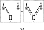
- FIG. 2 An example of multi-TRP communication is shown in Fig. 2 , where multiple physical downlink data channels are transmitted from two TRPs (that are e.g. connected by ideal backhaul) to a single UE.
- aspects to be considered in the down-selection may include backhaul latency, downlink control overhead, specification impact (including RAN2 specs), UE complexity (related to power control, timing adjustment, and blind detection), DCI/UCI design, scheduler flexibility, intra-UE PUCCH/PUSCH transmission, Rel-15 PDCCH blockage probability, and CSI feedback.
- the present disclosure may be applicable to single PDCCH transmission in multi-TRP.
- the PDCCH can schedule e.g. PDSCH/PUSCH/PUCCH for multiple TRPs.
- a single PDCCH (single DCI content) is transmitted from TRP1 to UE and it schedules respective PDSCHs (carrying respective codewords) transmitted from TRP1 and TRP2 to the UE.
- This means that single DCI content within the single PDCCH is applied to downlink data transmission from both the TRPs.
- one PDCCH transmitted from one of the TRPs schedules different code words (different PDCCHs).
- the respective code words transmitted to or received by two or more TRPs may be different or identical (e.g. to facilitate achieving spatial diversity gains).
- different layers of the same code word may be transmitted from multiple TRPs.
- DMRS demodulation reference signal
- a reference signal pattern is transmitted from an antenna port (or port or DMRS port) at the base station.
- a port may be implemented either as a single physical transmit antenna (or TRP), or as a combination of multiple physical antenna elements.
- the signal transmitted from each antenna port is not designed to be further deconstructed by the UE receiver: the transmitted RS (in particular demodulation reference signal) corresponding to a given antenna port defines the antenna port from the point of view of the UE, and enables the UE to derive a channel estimate for all data transmitted on that antenna port, regardless of whether it represents a single radio channel from one physical antenna or a composite channel from a multiplicity of physical antenna elements together comprising the antenna port.
- the transmitted RS in particular demodulation reference signal
- Different ports may be distinguished from each other by resource components such as cyclic shifts, combs (a comb defines a distinction of subcarriers, subcarriers with alternating subcarrier indices being grouped to different combs), and orthogonal cover codes (OCC).
- resource components such as cyclic shifts, combs (a comb defines a distinction of subcarriers, subcarriers with alternating subcarrier indices being grouped to different combs), and orthogonal cover codes (OCC).
- CDM code division multiplexing
- each CDM group uses a respective OCC (such as, in the case of two-symbol DMRS, Walsh-Hadamard TD(Time Division)-OCCs).
- the resource components may be combined to component sets, and the component sets assigned to ports.
- All the DMRS ports within the same CDM group may be assumed to be quasi-co-located (QCL) i.e. similar assumptions related to the channel correlation between those DMRS ports, for instance with respect to Doppler shift, Doppler spread, average delay, and delay spread, are made.
- QCL quasi-co-located
- a layer refers to one of different streams generated by spatial multiplexing.
- a layer can be described as a mapping of symbols onto the transmit antenna ports. Each layer is identified by a precoding vector of size equal to the number of transmit antenna ports and can be associated with a radiation pattern.
- the rank of the transmission is the number of layers transmitted.
- a codeword is an independently encoded data block, corresponding to a single Transport Block (TB) delivered from the Medium Access Control (MAC) layer in the transmitter to the physical layer, and protected with a cyclic redundancy check (CRC).
- TB Transport Block
- MAC Medium Access Control
- CRC cyclic redundancy check
- a layer is assigned per transmission time (TTI) interval which in LTE corresponds to the subframe.
- TTI can be a slot, mini-slot, or subframe.
- the TTI can be a slot, mini-slot, or subframe.
- layers, ranks, and codewords see also section 11.2.2.2 of S. Sesia, I. Toufik and M, Baker, LTE: The UMTS Long Term Evolution, Second Editi on.
- TTI determines the timing granularity for scheduling assignment.
- One TTI is the time interval in which given signals is mapped to the physical layer.
- the TTI length can vary from 14-symbols (slot-based scheduling) to 2-symbols (non-slot based scheduling).
- Downlink and uplink transmissions are specified to be organized into frames (10 ms duration) consisting of 10 subframes (1 ms duration).
- a subframe, in return is divided into slots, the number of slots being defined by the numerology / subcarrier spacing and the specified values range between 10 slots for a subcarrier spacing of 15 kHz to 320 slots for a subcarrier spacing of 240 kHz.
- the number of OFDM symbols per slot is 14 for normal cyclic prefix and 12 for extended cyclic prefix (see section 4.1 (general frame structure), 4.2 (Numerologies), 4.3.1 (frames and subframes) and 4.3.2 (slots) of the 3GPP TS 38.211 V15.0.0 (2017-12 )).
- assignment of time resources for transmission may also be non-slot based.
- the TTIs in non slot-based assignment may correspond to mini-slots rather than slots. I.e., one or more mini-slots may be assign to a requested transmission of data/control signaling.
- the minimum length of a TTI may conventionally be 2 OFDM symbols.
- the layers are mapped to the DMRS port numbers using port indication tables that are specified in Chapter 7 of 3GPP TS 38.212 V15.2.0.
- DCI format 1-1 and format 0-1 are used for scheduling of PDSCH and PUSCH, respectively.
- Each of these formats contains a field called "antenna ports" which is used to indicate to these tables for layer-to-port mapping.
- the specification in NR Rel. 15 for mapping layers-to-ports is based on the assumption of single TRP transmission. This means that the table contains entries where the DMRS ports within the same CDM group are mapped to multiple layers for transmission on a single TRP.
- mapping is applied to multi-TRP transmissions, for instance if layer1 is transmitted on TRP1 and layer2 is transmitted on TRP2, then the DMRS port mapping for these two layers is such that the two ports are assumed to be QCL-ed.
- This kind of mapping may be applied for single TRP or multiple TRPs that are sufficiently close to each other, as the DMRS ports can be assumed to be QCL-ed.
- the present disclosure proposes that the DMRS ports assigned to these layers are not QCL-ed due to the different geographical locations of the TRPs, i.e. not within the same CDM group. Therefore, either new tables with modified or additional entries may facilitate supporting non-QCL-ed DMRS port-to-layer mapping for multiple TRPs. Some other possible signaling modifications may further facilitate scheduling via single PDCCH.
- DCI format 1-1 (section 7.3.1.2.2 of 3GPP TS 38.212 V15.2.0), which is used for PDSCH scheduling, includes a field called transmission configuration indication (TCI) that is used to indicate one of the eight TCI states using 3 bits, if configured.
- TCI transmission configuration indication
- RRC Radio Resource Control
- Each TCI state contains parameters for configuring a quasi co-location relationship between one or two downlink reference signals and the DM-RS ports of the PDSCH. Further information about the different QCL types and other relevant information can be found in section 5.1.5 of 3GPP TS 38.212 V15.2.0. Accordingly, a single PDCCH (single DCI) has up to 3 bits for TCI signaling to indicate one of the eight configured states that signals the QCL assumption for a TRP and assumes same QCL assumption for other TRPs scheduled by the given PDCCH. With this QCL assumption, the TCI state information that is signaled via DCI is applicable in particular to single TRP transmission, because the same QCL association might not be valid for one different TRPs that are located far apart from each other. Some modifications may facilitate supporting independent TCI state signaling for multiple TRPs using a single PDCCH. For instance, TRPs that are geographically located apart should have a different QCL assumption, hence an independent TCI state signaling for each TRP.
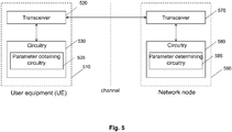
- the present disclosure provides a user equipment 510, which comprises a transceiver 520 (receiver/transmitter) and circuitry 530 (processing circuitry).
- the transceiver 520 (or "UE transceiver"), in operation, receives downlink control information (DCI) on a PDCCH for scheduling a plurality of transmissions or receptions between the UE and a plurality of transmission and reception points (TRPs, e.g., TRP1 and TRP2 shown in Figures 2 and 3 ) on a plurality of channels, wherein the DCI includes one or more indicators indicating one or more respective transmission parameters.
- DCI downlink control information
- the circuitry 530 (or "UE circuitry”, which may include transmission parameter obtaining circuitry 535), in operation, obtains, based on the one or more indicators and on a configuration, a plurality of values respectively of the one or more transmission parameters.
- the UE transceiver 520 performs the plurality of transmissions or receptions using a respective one of the plurality of values of the one or more transmission parameters for each of the plurality of transmissions or receptions.
- a network node 560 comprising a transceiver 570 and circuitry 580.
- the circuitry 580 (or “network node circuitry", which may include transmission parameter determining circuitry 585), in operation, determines a plurality of values respectively of one or more transmission parameters for a plurality of transmissions and receptions between a plurality of transmission and reception points, TRPs, and a user equipment, UE, and generates downlink control information, DCI, for scheduling the plurality of transmissions or receptions, the DCI including one or more indicators indicating the one or more respective transmission parameters, wherein the one or more indicators, in combination with a configuration, indicate the plurality of values respectively of the one or more transmission parameters.
- the network node transceiver 570 in operation, transmits the DCI on a PDCCH.
- the UE 510 and the network node 560 communicate with each other via at least one communication channel, e.g. a wireless channel or radio channel in a wireless or radio communication system such as NR, LTE, or LTE-A.
- a wireless channel or radio channel in a wireless or radio communication system such as NR, LTE, or LTE-A.
- the transceiver (the UE transceiver 520 and the network node transceiver 570) comprises hardware such as one or more antennas and software which controls the transmission and/or reception performed by the hardware.
- the present disclosure further provides a communication method for a user equipment (a "UE method”) and a communication method for a network node (a "network node method”).
- UE method a communication method for a user equipment
- network node method a communication method for a network node
- step S610 of the network node method a plurality of values respectively of one or more transmission parameters for a plurality of transmissions and receptions between a plurality of transmission and reception points, TRPs, and a user equipment, UE, are determined.
- step S620 of the network node method downlink control information (DCI) is generated for scheduling the plurality of transmissions or receptions.
- the DCI includes one or more indicators indicating the one or more respective transmission parameters, wherein the one or more indicators, in combination with a configuration, indicate the plurality of values respectively of the one or more transmission parameters.
- step S630 the DCI is transmitted on a PDCCH and, in step S635 of the UE method, received on the UE side.
- the plurality of respective values of the one or more transmission parameters are obtained based on the one or more indicator(s) and on the configuration.
- the plurality of transmissions or the plurality of receptions are performed using a respective one of the plurality of values of the one or more transmission parameters for each of the plurality of transmissions or receptions.
- the techniques disclosed herein may facilitate signaling to indicate separate DMRS port-to-layer mapping and TCI state for multiple TRPs using a single PDCCH. For instance, it may be facilitated not to increase DCI overhead (or not to increase the DCI overhead significantly) with an increasing number of TRPs. Moreover, reuse of techniques from existing specifications may be facilitated. Furthermore, the techniques disclosed may facilitate providing scalability and flexibility in view of a possibly large number of TRPs. Moreover, URLLC communication may be facilitated.
- the transmission (network node) and reception (UE) of the DCI on a PDCCH may be a single PDCCH in multi-TRP communication, as discussed above.
- the PDCCH schedules a plurality of transmissions/receptions each of which is performed respectively on one of a plurality of channels using one of the plurality of TRPs.
- the DCI includes one or more indicators which respectively indicate one or more transmission parameters.
- the transmission parameters may be QCL-related transmission parameters.
- the DCI may include one or both of the above-mentioned parameters TCI and an index of a configuration from a DMRS port indication table, and the value(s) of one or more of these parameters may be determined (network node) and obtained (UE).
- the respective values of the one or more of the transmission parameters are obtainable or derivable based on the one or more of the transmission parameters.
- one or more of the values is obtainable from a combination of the configuration and of the parameter in the DCI corresponding respectively to the value.
- the configuration may be a combination of a statically configured part (which may be defined in a standard) and a "semi-statically” configured part which is configured in higher-layer signaling such as RRC signaling.
- the semi-statically signaled configuration includes an element or parameter which enables the use of a "multi-TRP" configuration which is provided in the configuration, possibly in addition to a "single-TRP" configuration.
- the single-TRP configuration may include the above-mentioned configuration of the TCI state variable or the one or more port indication tables such as the above-mentioned port indication tables specified in Chapter 7 of 3GPP TS 38.212 V15.2.0 which may be referred to as single-TRP configuration tables.
- the multi-TRP configuration may include further port indication tables, e.g. tables that have been designed for the use in multi-TRP combination. These additional tables may be included in the static configuration or signaled via RRC.
- the multi-TRP configuration may provide additional pointers or parameters to the single-TRP configuration which may be included in an additionally configured table.
- the interpretation of the parameter in the DCI may be determined based on an enabling parameter or an RNTI (Radio Network Temporary Identifier) included in the configuration.
- the enabling parameter or the RNTI e.g. a particular RNTI among a plurality of configured RNTIs
- the UE determines one (e.g.
- single-TRP single-TRP
- multi-TRP multi-TRP
- the UE transceiver 520 performs the plurality of transmissions to or from the plurality of TRPs using, for each of the transmissions, or at least for two among the plurality of transmissions, a respective value of the transmission parameter. For instance, the UE uses respective TCI state values for respective TRPs. Furthermore, as an example, the UE may use a respectively different DMRS port indication value for transmission or reception to/from each of the plurality of TRPs.
- the respective values of the transmission parameter (e.g. DMRS port indication and/or TCI state) for the different TRPs may differ in their QCL assumption.
- the plurality of transmissions or receptions to or from the plural TRPs may be transmissions of the same data/code words or different data/code words.
- the respective code words of two code words being transmitted/received may be the same or different.
- the same data may be transmitted / received using the same or different MCS (modulation and coding scheme(s)) and / or redundancy version(s).
- different layers of a single code word may be transmitted or received to/from different TRPs.
- the plurality of transmissions or receptions may be uplink or downlink transmissions/receptions of data or control information on channels such as PDSCH, PUSCH, or PUCCH.
- channels such as PDSCH, PUSCH, or PUCCH.
- the UE transmits data and/or control information to a plurality of TRPs, or the plurality of TRPs transmit data and/or control information to the UE.
- the plurality of transmissions or receptions scheduled by the DCI are uplink transmissions from the UE to a plurality of TRPs, or the plurality of transmissions are downlink transmissions from a plurality of TRPs to the UE. It is further possible that the plurality of transmissions/receptions scheduled by the DCI include one or more uplink transmissions as well as one or more downlink transmissions.
- multi-TRP communication may include the case of each TRP respectively being provided with a RF block and baseband circuitry, and the case of one baseband circuitry being shared between a plurality of TRPs each of which comprises a respective RF block.
- the network node 560 include one or more TRPs.
- one or more TRPs are included in the network node transceiver 570.
- the plurality of TRPs may also include TRPs which are not included in the network node 560.
- the network node may determine value(s) for the transmission parameter(s) and transmit these values to another baseband circuitry, possibly included in another network node, via an ideal or non-ideal backhaul link.
- the network node may determine the transmission parameters by receiving control information over an ideal or non-ideal backhaul link from another network node/ baseband circuitry.
- the network node transceiver 570 in operation, performs at least one of the plurality of transmissions or receptions using a respective one of the plurality of values of the one or more transmission parameters for each of the plurality of transmissions or receptions.
- the at least one transmission or reception is performed between the UE and at least one of the plurality of TRPs.
- the network node method further contains a transmission or reception step S660 of performing at least one (one, more, or each) of the plurality of transmissions. Therein, one, more, or each of the plurality of TRPs are respectively used.
- the one or more transmission parameters include at least one of a DMRS, demodulation reference signal, port indication and a transmission configuration indication, TCI, state.
- a DMRS demodulation reference signal
- TCI transmission configuration indication
- the present disclosure provides several embodiments involving different elements such as RNTIs, or enabling parameters in RRC signaling, combination tables which may be signaled in RRC or be statically configured, and combinations of the aforementioned elements. In the following, some embodiments will be described in further detail.
- the configuration includes a RNTI, or a RNTI is derivable from the configuration, which is used by the network node to scramble a CRC (cyclic redundancy check) appended to the DCI.
- the UE circuitry 530 in operation, descrambles the CRC appended to the DCI using the RNTI, wherein the RNTI indicates the value of at least one of the plurality of values of the transmission parameters, either alone or in combination with one of the indicators in the DCI signaling.
- the RNTI (in particular, the numerical value of the RNTI) may correspond to the value of the transmission parameter.
- the DCI field of the same parameter may be used for the value of the parameter of a first transmission or reception to or from a first TRP, while the value indicated by the RNTI is a value of the parameter for a second transmission or reception to or from a second TRP.
- the RNTI may indicate that for the same or another transmission parameter, the corresponding field in the DCI is to be interpreted as a value representing plural (e.g. two) values for the transmission parameter for a plurality of transmissions/receptions via plural TRPs, wherein the mapping between the value in the DCI and the plural values may be defined by a combination table included in the configuration.
- the present disclosure provides some embodiments based on an RNTI based approach.
- RNTI RNTI based approach.
- RNTI Several possibilities are possible as to which RNTI is used in particular. For instance, either a new UE specific RNTI may be introduced for multi-TRP specific signaling, or a UE specific RNTI which already serves some function, such as a MCS-C-RNTI (MCS Cell RNTI), may be enhanced in functionality to additionally indicate multi-TRP specific signaling.
- MCS-C-RNTI MCS Cell RNTI
- RNTI-based embodiments of the present disclosure may be implemented without additional DCI overhead. Rather than including different values of a given transmission parameter in the DCI, an additional value of a given parameter may be obtainable from the RNTI or from a table at which the RNTI points. At the same time, independent indication for different TRPs may be facilitated. Furthermore, a unified approach to distinct signaling issued, e.g. DMRS and TCI signaling, is provided as the RNTI may serve as an indicator for DMRS port indication, TCI state indication, both issues or some additional fields.
- DMRS DMRS and TCI signaling
- a new UE-specific RNTI is configured by RRC, or an existing RNTI such as MCS-C-RNTI is reused, e.g. provided with additional functionality, where
- step a. may be taken alone and independent of steps b. and c.
- steps b. and c. may be performed without step a.
- the multi-TRP RNTI is used i) for indication of new DMRS table for multi-TRP, ii) for indication of 2 or more TCI state values for 2 TRPs or multi-TRP, or iii) for indication of new DMRS table for multi-TRP the above-mentioned steps 1. to 4. of the multi-TRP communication method may vary.
- the use of the existing framework includes use of a single-TRP DMRS port indication table.
- step 4 includes step a., in case ii), step 4) includes steps b., and c., and in case iii), step 4) includes steps a) to c).
- the RNTI is a dedicated RNTI or a given RNTI enhanced by multi-TRP functionality which is configured.
- K RNTI candidate values are configured or derivable from the configuration, as will be described further.
- Fig. 7 shows an exemplary structure of parameter obtaining circuitry 535, including descrambling circuitry 736 and including at least one of table selection circuitry 737 and TCI state obtaining circuitry 738.
- the RNTI is used for an indication of a DMRS table for multi-TRP communication.
- the configuration includes a first DMRS port indication table and a second DMRS port indication table.
- the UE circuitry 530 descrambles a cyclic redundancy check, CRC, appended to the DCI using a radio network temporary identifier, RNTI, included in or derivable from the configuration.
- the RNTI indicates that the second DMRS port indication table is to be used for the at least one of the plurality of transmissions or receptions.
- the UE transceiver 520 in operation, performs, in accordance with a result of successfully performing the descrambling of the CRC using the RNTI, at least one of the plurality of transmissions or receptions using the second DMRS port indication table, wherein the indicator indicates the DMRS port indication from the second DMRS port indication table.
- Table 1 is an exemplary DMRS port indication table which may be used for multi-TRP communication in the case of type1 DMRS configuration and a one-symbol length. Accordingly, Table 1 is an example of the above-mentioned second DMRS port indication table (or "multi-TRP port indication table"), whereas the first DMRS port indication table may be a "single-TRP" DMRS port indication table as mentioned above. As can be seen from Fig. 4 , ports 0 and 1 are QCLed (since they are in the same CDM group), and ports 2 and 3 are QCLed as well.
- the column "Number of DMRS CDM groups without data” indicates the number of CDM groups on which reference signals (rather than data) are signaled or which are occupied by another UE for DMRS transmission/reception (and thus are without data for the given user equipment under consideration).
- Table 1 DMRS port indication table DMRS port indication table for type 1 config with 1symbol Codeword 0 enabled, Codeword 1 disabled Value Number of DMRS CDM group(s) without data DMRS port(s) 0 1 0 1 1 1 1 3 2 0 4 2 1 5 2 2 6 2 3 7 2 0,2 8 2 0,3 9 2 1,2 10 2 0-2 11 2 1-3 12 2 0-3 13-15 Reserved Reserved
- the column value includes indices of the different rows corresponding to DMRS configurations.
- a DMRS configuration from among the rows is dynamically scheduled to the UE by a four-bit field in the DCI.
- the DMRs port indication is one of the transmission parameters based on which the plurality of transmissions or receptions is performed.
- This four bit field is an indicator which indicates one of the indices corresponding to the "Value" column denoting a DMRS port indication from the table.
- the DMRS port indication to be used for the plurality of transmissions or receptions is derived from the second DMRS port indication table rather than the first DMRS port indication table if the RNTI used for the descrambling is the RNTI having the multi-TRP functionality.
- the indicator in the DCI indicates an entry from the "value" column of the second rather than the first DMRS port indication table, and the value corresponds to a plurality of ports, as defined in the respective row in the "DMRS port(s)" column, which including a plurality of non-QCLed ports assigned respectively to a plurality of TRPs.
- Table 1 shows a case where only one code word is enabled (codeword1) is enabled. In such a case, different layers of the code word are transmitted or received to or from different TRPs.
- the rows indicated by values 7 to 12 may be used for multi-TRP transmissions or receptions.
- the indicated port combinations, (0,2) and (0,3), are both non-QCLed, and can thus be used for transmissions using two ports.
- Entries 10 to 12 each denote combinations including at least two QCLed ports. If these combinations are for three layers (entries 10, 11) or four layers (entry 12), QCLed ports are mapped to the same TRP whereas ports belonging to different CDM groups are mapped to different TRPs.
- Table 1 is an example, and the present disclosure may be applied using different DMRS port indication tables. For instance, more than one code word may be enabled. In this case layers of different code words may be mapped to different TRPs.
- the result of successfully descrambling the RNTI may be used for indicating a TCI state of a transmission or reception to or from one of the plurality of TRPs.
- the indicator included in the DCI indicates a first value from among the plurality of values of the TCI state.
- the RNTI is one of K RNTI candidates, wherein a first of the K RNTI candidates is included in the configuration and the RNTI candidates are K subsequent integers respectively indicating K configured TCI states signaled by Radio Resource Control, RRC, and the UE circuitry 530, in operation, determines the first value of the TCI state based on the indicator and obtains a second value from among the plurality of values of the TCI state based on a result of successfully descrambling the CRC appended to the DCI using, as the RNTI, the RNTI candidate indicating the TCI state to be used as the second value from among the K TCI states.
- the RNTI may or may not additionally indicate use of the second DMRS port table as described above.
- the RNTI is one of a K candidates (K being an integer). Since K possible values are available which the RNTI may take (which the network node circuitry 580 may use to scramble the DCI CRC), the plurality of RNTI candidates may be considered a multi-valued (or multiple valued) RNTI or an RNTI configured with more than one values.
- the value of the TCI state for transmission or reception to/from the second TRP is determined based on a mapping between RNTI value candidates and (RRC) configured TCI states.
- the index value or parameter value of the second TCI state for transmission and reception point TRP2 may be calculated as follows, while the value of TCI state for a transmission and reception point TRP1 is indicated by the indicator (bit field or bit map) included in the DCI.
- the indicator bit field or bit map
- RNTI candidates are mapped to TCI state values by a mod (modulo) function.
- mod modulo
- other functions or operations to determine the mapping of RNTIs and respective TCI states may be applied.
- a counter may be used by the UE which is incremented with each attempt of descrambling the DCI CRC.
- the DCI CRC may be scrambled by the network node by another configured non-multi-TRP related RNTI such as a C-RNTI not having additional multi-TRP functionality (a "non-multi-TRP-RNTI").
- the transceiver 520 may perform one or more further attempts to descramble the DCI using a non-multi-TRP RNTI.
- the descrambling attempts with the multi-TRP RNTI candidate(s) may be performed before or, if necessary after the attempts using non-multi-TRP RNTIs.
- Using the multi-TRP RNTI candidates first may facilitate prioritizing TRP communication, for example if the channel characteristics are critical as to frequently require multi-TRP transmissions.
- using the non-multi TRP RNTI first may facilitate accelerating the processing or reducing the required processing in a case where single-TRP communication is likely.
- the multiple RNTI candidates are configured. It may be sufficient that only an initial RNTI value (or RNTI candidate) is signaled to the UE via RRC.
- the UE may assume that K subsequent numbers (e.g. integers) of RNTI values also belong to this multi-valued RNTI or candidate set of K RNTI candidates and which can be used for scrambling the RNTI (the multi TRP RNTI or possibly, an enhanced C-RNTI) on the network node side.
- K depends on the number of TCI states that are configured by dynamic or semi-static indication (in the RRC). Out of a total number of e.g. 128 TCI states included in a static configuration (e.g.
- the network node selects e.g. 8 states and signals these 8 states via RRC to the UE.
- 8 may correspond to a maximum number of RRC configurable TCI states corresponding to the size of the bit field (e.g. 3 bits) in the DCI.
- the number K of RNTIs may equal 8.
- a RNTI being derivable from the configuration thus includes the case in which the RNTI used for scrambling / successfully descrambling the DCI CRC is one of K adjacent/subsequent or otherwise related values, e.g. integer values that are obtainable/derivable from an initial RNTI signaled in the RRC configuration by a numerical operation such as incrementing or decrementing.
- the K RNTI candidates may also indicate a plurality of values of TCI state, e.g. for a second TRP (TRP3) and a third TRP (TRP3). Then, if 4 states rather than an allowed maximum number of 8 states are RRC-configured, 16 respective RNTI candidates may be mapped to combinations of respective TCI states for TRP2 and TRP3.
- At least one of the indicator in the DCI and the RNTI indicates a multi-TRP TCI state, a multi-TRP TCI state comprising more than one TCI states for transmission or reception respectively to or from more than one TRP.
- the multi-TRP state may be a combination of respective TCI states for a plurality of TRPs such as TRP2 and TRP3, as described above.
- steps 1. to 4. are performed, wherein the TCI state index (the TCI transmission parameter included in the DCI) contains information about more than one TRP.
- the TCI states to be signaled via RRC may be configured differently.
- a TCI index corresponding to the TCI state transmission parameter may be configured to indicate the TCI-state information for more than one TRPs. This may result in an increased number of indices, for instance, the DCI field for TCI indication may or may not be redefined to have more than 3 bits.
- the exact number of configured multi-TRP TCI states may depend on the scenarios (e.g. the number of configured TRPs and/or the locations of TRPs with relative to the UE and relative to each other).
- the TCI index may be configured to indicate the TCI state information for more than one TRPs by means of a table which maps the TCI index to more than one TCI state. Shown below are
- Table 2 and Table 3 indicates TCI state indices for 1 additional TRP, and Table 3 indicates the TCI state for 2 additional TRPs.
- Table 2 TCI state indices for 1 (additional) TRP Index TCI-State 0 State1 1 State2 2 State3 3 State4 4 State5 5 State6 6 State7 7 State3
- Table 3 TCI states for 2 additional TRPs Index TRPs combination TCI-State 0 TRP2, TRP3 State1, State2 1 TRP2, TRP3 State2, State5 2 TRP2, TRP3 State3, State0 3 TRP2, TRP3 State4, State3 4 TRP2, TRP3 State5, State6 5 TRP2, TRP3 State6, State1 6 TRP2, TRP3 State7, State8 7 TRP2, TRP3 State8, State7
- the TCI state transmission parameter in the DCI, the RNTI value successfully descrambling the CRC, or both the TCI state transmission parameter and the RNTI value may, in accordance with a configuration possibly signaled in the RRC, point to a multi TRP TCI state table such as the Table 3 for two TRPs . Whether the DCI parameter and/or the RNTI are to be interpreted by the UE as pointing to a single TRP table (Table 2) or a multi-TRP table (Table 3) may be RRC configured.
- multi-TRP Table 3 in the column "TCI state”, may point to the TCI states of Table 2.
- Table 3 refers to (depends on) Table 2
- tables of both types may be configured or signaled via RRC.
- multi-TRP states may also be defined in the standard and statically configured.
- a multi-TRP table may be configured in the RRC which does not refer to single TRP states from a single-TRP TCI table, but may rather refer to statically configured multi-TRP states (e.g. to indexes of multi-TRP states in the static configuration).
- Table 3 shown above maps index values to combinations of TCI states to be applied for combinations of TRPs. Therefore, Table 3 may be considered a combination table.
- combination tables are used to indicate values for multi-TRP communication.
- the disclosure shows the possibility to create or enable intermediate combination tables via RRC for multi-TRP signaling.
- a generic structure of the combination table may contains a number of indices wherein each index of a given table corresponds to a row and indicates a combination of different TRP IDs and a corresponding combination of indices of DCI bitmap field for a given parameter (such as DMRS port indication, TCI state, etc.).
- a corresponding bitmap in the DCI may be used to indicate the index of the new combination table instead of the original indication of the corresponding parameter/index (e.g. the index of the "value column of Table 1 or the "index column of Table 2”) for the single TRP case.
- Table 4 exemplifies a possible generic structure of a single-TRP indication Table, and Table 4 shows a generic structure of a multi-TRP combination table.
- Table 4 Generic structure of single-TRP indication table Index Information for single TRP 0 InfoA 1 InfoB 2 .... 3 .... ... .... .... .... Z InfoW
- Table 5 Generic structure of a multi-TRP combination table Index TRP combinations Combination of Index of existing table for X 0 TRP1 0 1 TRP2 1 2 TRP1, TRP2 0, 0 3 .... ... .... .... .... Z TRP1, TRP2 2,3
- single-TRP parameter indication tables examples include DMRS port indication tables and TCI state indication tables (see Table 2). It should be noted that although single TRP parameter indication Table 4 has one column for "Information for single TRP", such information may be divided among more columns e.g. in a DMRS port indication table including columns of information respectively about DMRS groups without data and DMRS ports.
- a single-TRP parameter indication table such as Table 4, may have Z rows (indices) in accordance with the size of the corresponding field in the DCI.
- single-TRP is used to distinguish from tables or parameters that are particularly designed or configured for multi-TRP applications as described in this disclosure.
- "single-TRP” DMRS port indication tables from the standard, as mentioned above, may also to some extend be applicable to multi-TRP communication.
- the combination tables are combined with the single TRP tables to indicate parameter value indication.
- Single-TRP tables are also referred to as "existing” tables as they may be used for non-multi-TRP scenarios as well and as they need to be present (“existent") so that the combination tables can refer to them.
- "X" denotes a given transmission parameter, e.g. a DMRS port indication of a TCI state, as indicated by the single-TRP indication table.
- Table 3 satisfies the structure of generic combination Table 5 and can thus be considered an example of a multi-TRP combination table. Accordingly, the techniques shown in the section about "combination table based embodiments" may also be applied to combination Table 3 shown in the preceding section of this disclosure, for instance configuring, RRC signaling, enabling and indexing of the RRC combination table.
- the combination table may contain 3 columns and Z indices (Z being the same number of indices as for the corresponding single-TRP parameter indication table), as can be seen from Table 5.
- the first column is the index to be signaled via the DCI.
- the second column is the combination of TRPs, e.g. the TRP sets respectively including one or more TRPs, corresponding to which the information for parameter X needs to be signaled.
- the third column is the combination of indices (a set of "value candidates") that point to the existing (single-TRP) table and indicate information for parameter X for the corresponding TRPs for that index.
- the number of TRPs in the "TRP combinations" column (the second column) is the same as the number of indices in the "Combination of Index” column (the third column).
- the indexes in the third column correspond to the TRPs in the second column in the order of listing (the first value corresponds to the first TRP listed in the same row, the second value to the second TRP, and so on).
- the combination table may be referred to as an "intermediate" combination table because it is inserted in the chain/hierarchy of reference in an intermediate position which may for example be as follows: parameter in DCI ⁇ intermediate combination table ⁇ (multiple values of) single-TRP indication table ⁇ static configuration.
- the configuration includes a set of mappings between TRP sets and value candidate sets of value candidates of the one or more transmission parameters, and at least one of the one or more indicators indicator included in the DCI indicates, from among the set of mappings, the mapping between one among the TRP sets to be used as the plurality of TRPs and one among the value candidate sets to be used as the plurality of values of the one or more transmission parameters to be used for the plurality of transmissions or receptions.
- Exemplary parameter obtaining circuitry 535 for embodiments where the configuration includes a set of mappings between TRP sets and value candidate sets is shown in Fig 8 .
- the parameter obtaining circuitry includes combination table selection circuitry (or combination table enabling circuitry) 836 and plural value obtaining circuitry 837.
- the set of mappings between TRP sets and value candidate sets corresponds is defined by the intermediate combination table.
- Each row from the combination table may respectively define one mapping from among the set of mappings.
- the TRP sets correspond to the respective entries in the "TRP combination" column of the combination table. Based on an indication in the DCI (a value of the transmission parameter), one of the TRP sets is determined / obtained to become the plurality of TRPs used for transmission or reception, in association with the one or more of indices in the column "Combination of Index of existing table for X" from Table 5.
- combination Table 5 includes entries of single TRPs (in the rows with indexes "0" and "1"). Accordingly, in addition to indicating a plurality of transmissions and receptions to or from multiple TRPs, the DCI signaling in combination with the combination table may indicate a single value for a given transmission parameter for a transmission or reception using a one TRP.
- a combination table including one or more rows referring to a single TRP may facilitate flexibly switching between different TRPs as well as switching between single TRP transmissions/ receptions and multi-TRP transmissions/ receptions.
- the bit field for parameter X points to a row of the combination table, and the number of rows/ indexes of the combination table may be the same or smaller than the number of rows of the parameter indication table (Table 4). Accordingly, embodiments using a set of mappings (a combination table) may be implemented without causing additional DCI overhead. However, the number of rows of the combination table may in general also be larger than the number of rows of the parameter indication table. In general, a flexible and scalable technique is provided which may facilitate communication between a UE and a large number of TRPs. Moreover, the set of mappings may be applicable for different DCI fields designed to be used for single-TRP applications or without consideration of the multi-TRP case, and one or more DCI fields at a time instance.
- a combination table for a parameter X may be configured as a new table, and different alternatives (e.g. statically and dynamical) configuration may be applied.
- the set of mappings comprises M mappings from among N statically configured mappings, M being equal to or smaller than N, and the UE transceiver 520, in operation, receives M indices indicating respectively the M mappings which are signaled by the network node transceiver 570 via RRC, and the at least one indicator indicates the index which indicates the mapping between the plurality of TRPs and the plurality of values of the one or more transmission parameters to be used for the plurality of transmissions or receptions.
- a combination table may be statically configured including a number N of rows corresponding to mappings between TRP set and parameter candidate sets and correspondingly, N indices that cover various combinations, (e.g. all possible combinations TRPs or a set of desired / required combinations of TRPs).
- the number N of statically configured indexes constitutes a superset of indexes.
- the set of M indices corresponds to the set of M mappings between TRP sets and value candidate sets from which the parameter to be used for the transmissions or receptions is selected and indicated by the DCI field.
- the network node dynamically indicates, using the DCI bit field for parameter X, one index of the (sub)set of mappings of to the UE, of which the UE is informed via RRC.
- the combination table (rather than only a subset of indices of a statically configured combination table) may be signaled via RRC signaling.
- the combination table may have the structure of Table 5.
- content of a mapping table which defines the set of mappings between TRP sets and (index) value candidates is signaled by RRC.
- the RRC dynamically configures a new combination table which defines the set of mappings, and the entire table (e.g. lists of the entries of the respective columns) is signaled to the UE via RRC signaling.
- the length of the RRC-configured configuration table may vary depending, for example on the number of TRPs and on the scenario.
- the network node dynamically indicates, using the DCI bit field for parameter X, one index from the RRC-configured combination table to the UE.
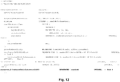
- the RRC signaling to indicate the list of indices in the new combination table for parameter X may be signaled in an information element "PDSCH-Config" of the RRC, as shown in Fig. 9 , where the definition concerning parameter X is shown in bold.
- parameter X may for instance be DMRs port indication and/or TCI state. It is through this information element that the content of each index of the combination table is informed to the UE(s), similar to other parameters also included in this information element.
- the UE gets information including the number of indices of the combination table and the content of each index (corresponding sets of TRPs and the sets of value candidates (values of single-TRP indication table indices of the respective rows) of the combination table.
- the field in the DCI directly points to the (single-TRP) indication table such as a DMRS port indication table or a table of configured TCI states.
- the (single-TRP) indication table such as a DMRS port indication table or a table of configured TCI states.
- the format of the combination table may be statically defined including the number of columns and the information to be received in each column (the type of information included in each column, e.g. "TRP set” and “Combination of indices of existing table”).
- the format of the combination table (or combined table) may be static and the same regardless of the number of TRPs.
- the PDSCH configuration element (PDSCH-Config) of the RRC indicates the number of indices and the content of each index.
- the number of indices and the content of the table is different dependent on the number of TRPs to be included for which the combination table is used (the number of TRPs from which the respective TRP sets are selected/formed).However, the format of the table, including the number of columns and their interpretation, may be the same regardless of the number of TRPs for which a parameter X needs to be indicated. Thus, no additional signaling is needed to indicated how many TRPs are involved since the number of TRPs is implicit in the content of the combination table.
- Table 6 is an example of a combination table for a two-TRP case
- Table 7 is an example of a combination table for a four-TRP case.
- Table 7 Two-TRP combination table for indication of parameter X Index TRP combinations Combination of Index of existing table for X 0 TRP1 0 1 TRP2 1 2 TRP1, TRP2 0, 0 3 .... ... .... .... ....
- TRP1, TRP2 2,3 Table 8 Four-TRP combination table for indication of parameter X Index TRP combinations Combination of Index of existing table for X 0 TRP1 0 1 TRP2 1 2 TRP3 3 3 TRP4 0 4 TRP1, TRP4 1,4 5 TRP1, TRP2, TRP3 1,4,0 6 TRP1, TRP2, TRP3, TRP4 5,2,3,6 ;
- a combination table is configured (via RRC and/or static combination), then this combination table is to be used for indicating the values for a parameter X or more parameters.
- a combination table is configured, different enabling mechanisms to enable the multi-TRP combination table to be used or not (e.g. to "switch" multi-TRP communication on or off) may be implemented.
- parameter can be included in a PDCCH information element (IE) to indicate to the UE if the new combination table is to be used and the DCI bit field for a given parameter should point to this new combination table or not.
- IE PDCCH information element
- the presence of a combination table as well as enabling of use of this combination table may be signaled in the ControlResourceSet information element of the RRC signaling.
- the UE transceiver 520 in operation, receives an enabling parameter which indicates that the plurality of transmissions or receptions are to be performed based on the set of mappings and which is signaled by RRC, and the UE circuitry 530, in operation, determines, based on the enabling parameter, that the plurality of transmissions or receptions are to be performed based on the set of mappings.
- parameter_X may be a parameter for DMRS port indication, TCI state indication, or some other parameter.
- an enabling parameter such as DMRSPortMultiTRP-CombinedTableIndicationInDCI is used to inform the UE that combined table for multi-TRP is enabled that is used to point to existing DMRS port indication tables.
- a parameter such as TCIStateMultiTRP-CombinedTableIndicationInDCI may be used to inform the UE that a combination table for multi-TRP is enabled that is used to point to TCI states (which may be defined in a single-TRP TCI state indication table).
- the respective enabling parameter does not carry actual content/information of the respective combination table, it merely is an indication for enabling the use of the combination table.
- the actual content of the combination table may for instance be included in the PDSCH-Config information element, as described above.
- a UE specific RNTI may be newly configured, or an existing RNTI enhanced with additional functionality, to indicate the enabling of a combination table. If the DCI CRC is scrambled with this RNTI, then the UE assumes that the combination table is used and the bit field in the DCI for parameter X points to index of this combination table.
- the UE circuitry 530 descrambles a CRC, appended to the DCI using a RNTI included in or derivable from the configuration, wherein the RNTI indicates that the plurality of transmissions or receptions are to be performed based on the set of mappings (e.g. the combination table), and determines, based on a result of successfully descrambling the CRC appended to the DCI using the RNTI, that the plurality of transmissions or receptions are to be performed based on the set of mappings.
- the set of mappings e.g. the combination table
- the functionality of the RNTI described in this section may be combined with the functionality of an RNTI described in the previous section disclosing the RNTI-based approach. For instance, a set of RNTI candidates being subsequent integers with which successive descrambling attempts by the UE are performed, rather than to a single TCI state indication table.
- Table 9 is a DMRS port indication table for configuration type 1 with 1-symbol length.
- the table has 16 indices. If a combination table for DMRS port indication, such as Table 10, is configured and enabled, instead of directly signaling the index of the DMRS port indication table, 4 bits (i.e. a four-bit DCI field for DMRS port indication) are used to indicate the index of the combination table on the right, that points to the DMRS port indication table for 2 TRPs.
- the Exact combinations, number of indices, etc. can be configured by RRC depending up on the scenario.
- Table 10 merely illustrates an exemplary structure of a combination table and the values are not necessarily applicable for Table 9. Rather, the entries are to be understood as placeholders.
- Table 9 DMRS port indication table DMRS port indication table for type 1 config with 1symbol Codeword 0 enabled, Codeword 1 disabled Value Number of DMRS CDM group(s) without data DMRS port(s) 0 1 0 1 1 1 2 1 0,1 3 2 0 4 2 1 5 2 2 6 2 3 7 2 0,1 8 2 2,3 9 2 0-2 10 2 0-3 11 2 0,2 12-15 Reserved Reserved Table 10: Exemplary structure of DMRS combination table 2-TRP combination table for DMRS port indication Value Multi-TRP IDs Indices of DMRS port indication table 0 1 0 1 1, 2 0,1 2 2 3 3 1 5 4 1 1 5 2 1 6 2 3 7 1,2 1,4 8 1,2 1,6 15 ... ....
- a combination table may be used for multi-TRP TCI state signaling.
- Table 11 shows an indication table usable for up to eight TCI states.
- An existing TCI bit field with 3 bits can indicate one of the eight configured states of Table 11 for one TRP if a TCI state combination table is not enabled.
- a TCI state combination table such as Table 12 is enabled, instead of directly signaling the index of the TCI state, the 3 bits in the DCI used to indicate the index of the combination table (Table 12), that points to the TCI states for 2 TRPs (e.g. two separate states from Table 11).
- Table 12 the exact combinations (as well as. which of the total available statically configured TCI states are to be activated), number of indices, etc.
- Table 11 TCI state indication table TCI state signaling for up to 8 states Value TCI state 0 State 1 1 State 2 2 State 3 3 State 4 4 State 5 5 State 6 6 State 7 7 State 8
- Table 12 Exemplary structure of TCI state combination table.
- 2-TRP combination table for TCI state signaling Value Multi-TRP IDs Indices of TCI states 0 1 0 1 1,2 0,1 2 2 3 3 1 5 4 1 1 5 2 1 6 2 3 7 1,2 1,4
- the present disclosure can be realized by software, hardware, or software in cooperation with hardware.
- Each functional block used in the description of each embodiment described above can be partly or entirely realized by an LSI such as an integrated circuit, and each process described in the each embodiment may be controlled partly or entirely by the same LSI or a combination of LSIs.
- the LSI may be individually formed as chips, or one chip may be formed so as to include a part or all of the functional blocks.
- the LSI may include a data input and output coupled thereto.
- the LSI here may be referred to as an IC, a system LSI, a super LSI, or an ultra LSI depending on a difference in the degree of integration.
- the technique of implementing an integrated circuit is not limited to the LSI and may be realized by using a dedicated circuit, a general-purpose processor, or a special-purpose processor.
- a FPGA Field Programmable Gate Array
- a reconfigurable processor in which the connections and the settings of circuit cells disposed inside the LSI can be reconfigured may be used.
- the present disclosure can be realized as digital processing or analogue processing. If future integrated circuit technology replaces LSIs as a result of the advancement of semiconductor technology or other derivative technology, the functional blocks could be integrated using the future integrated circuit technology. Biotechnology can also be applied.
- the present disclosure can be realized by any kind of apparatus, device or system having a function of communication, which is referred as a communication apparatus.
- Such communication apparatus include a phone (e.g., cellular (cell) phone, smart phone), a tablet, a personal computer (PC) (e.g., laptop, desktop, netbook), a camera (e.g., digital still/video camera), a digital player (digital audio/video player), a wearable device (e.g., wearable camera, smart watch, tracking device), a game console, a digital book reader, a telehealth/telemedicine (remote health and medicine) device, and a vehicle providing communication functionality (e.g., automotive, airplane, ship), and various combinations thereof.
- a phone e.g., cellular (cell) phone, smart phone
- a tablet e.g., a personal computer (PC) (e.g., laptop, desktop, netbook)
- a camera e.g., digital still/video camera
- a digital player digital audio/video player
- a wearable device e.g., wearable camera, smart watch, tracking device
- game console
- the communication apparatus is not limited to be portable or movable, and may also include any kind of apparatus, device or system being non-portable or stationary, such as a smart home device (e.g., an appliance, lighting, smart meter, control panel), a vending machine, and any other "things" in a network of an "Internet of Things (IoT)".
- a smart home device e.g., an appliance, lighting, smart meter, control panel
- vending machine e.g., a vending machine, and any other "things” in a network of an "Internet of Things (IoT)".
- IoT Internet of Things
- the communication may include exchanging data through, for example, a cellular system, a wireless LAN system, a satellite system, etc., and various combinations thereof.
- the communication apparatus may comprise a device such as a controller or a sensor which is coupled to a communication device performing a function of communication described in the present disclosure.
- the communication apparatus may comprise a controller or a sensor that generates control signals or data signals which are used by a communication device performing a communication function of the communication apparatus.
- the communication apparatus also may include an infrastructure facility, such as a base station, an access point, and any other apparatus, device or system that communicates with or controls apparatuses such as those in the above non-limiting examples.
- an infrastructure facility such as a base station, an access point, and any other apparatus, device or system that communicates with or controls apparatuses such as those in the above non-limiting examples.
- the present disclosure provides a user equipment, UE, comprising a transceiver which, in operation, receives, on a physical downlink control channel, PDCCH, downlink control information, DCI, for scheduling a plurality of transmissions or receptions between the UE and a plurality of transmission and reception points, TRPs, on a plurality of channels, the DCI including one or more indicators indicating one or more respective transmission parameters, and circuitry which, in operation, obtains, based on the one or more indicators and on a configuration, a plurality of values respectively of the one or more transmission parameters, wherein the transceiver, in operation, performs the plurality of transmissions or receptions using a respective one of the plurality of values of the one or more transmission parameters for each of the plurality of transmissions or receptions.
- a transceiver which, in operation, receives, on a physical downlink control channel, PDCCH, downlink control information, DCI, for scheduling a plurality of transmissions or receptions between the UE and a
- the one or more transmission parameters include at least one of a DMRS, demodulation reference signal, port indication and a transmission configuration indication, TCI, state.
- the configuration includes a RNTI, radio network temporary identifier, or the RNTI is derivable from the configuration, and the UE circuitry, in operation, descrambles a CRC appended to the DCI using the RNTI, wherein the RNTI indicates the value of at least one of the plurality of values of the transmission parameters, either alone or in combination with the at least one indicator in the DCI signaling.
- the configuration includes a first DMRS port indication table and a second DMRS port indication table
- the circuitry in operation, descrambles a cyclic redundancy check, CRC, appended to the DCI using a radio network temporary identifier, RNTI, included in or derivable from the configuration, wherein the RNTI indicates that the second DMRS port indication table is to be used for the at least one of the plurality of transmissions or receptions
- the transceiver in operation, performs, in accordance with a result of successfully performing the descrambling of the CRC using the RNTI, at least one of the plurality of transmissions or receptions using the second DMRS port indication table, wherein the indicator indicates the DMRS port indication from the second DMRS port indication table.
- the indicator indicates a first value from among the plurality of values of the TCI state
- the RNTI is one of K RNTI candidates, wherein a first of the K RNTI candidates is included in the configuration and the RNTI candidates are K subsequent integers respectively indicating K configured TCI states signaled by Radio Resource Control, RRC, and the circuitry, in operation, determines the first value of the TCI state based on the indicator and obtains a second value from among the plurality of values of the TCI state based on a result of successfully descrambling the CRC appended to the DCI using, as the RNTI, the RNTI candidate indicating the TCI state to be used as the second value from among the K TCI states.
- RRC Radio Resource Control
- the indicator indicates a first value from among the plurality of values of the TCI state
- the circuitry descrambles a cyclic redundancy check, CRC, appended to the DCI using a radio network temporary identifier, RNTI, included in or derivable from the configuration
- the RNTI is one of K RNTI candidates, wherein a first of the K RNTI candidates is included in the configuration and the RNTI candidates are K subsequent integers respectively indicating K configured TCI states signaled by RRC
- the circuitry determines the first value of the TCI state based on the indicator and obtains a second value from among the plurality of values of the TCI state based on a result of successfully descrambling the CRC appended to the DCI using, as the RNTI, the RNTI candidate indicating the TCI state to be used as the second value from among the K TCI states.
- At least one of the indicator and the RNTI indicates a multi-TRP TCI state, a multi-TRP TCI state comprising more than one TCI states for transmission or reception respectively to or from more than one TRP.
- the configuration includes a set of mappings between TRP sets and value candidate sets of value candidates of the one or more transmission parameters, and at least one of the one or more indicators indicates, from among the set of mappings, the mapping between one among the TRP sets to be used as the plurality of TRPs and one among the value candidate sets to be used as the plurality of values of the one or more transmission parameters to be used for the plurality of transmissions or receptions.
- the set of mappings comprises M mappings from among N statically configured mappings, M being equal to or smaller than N, and the transceiver, in operation, receives M indices indicating respectively the M mappings which are signaled by RRC, and the at least one indicator indicates the index which indicates the mapping between the plurality of TRPs and the plurality of values of the one or more transmission parameters to be used for the plurality of transmissions or receptions.
- the transceiver in operation, receives content of a mapping table which defines the set of mappings, the content of the mapping table being signaled by RRC.
- the transceiver in operation, receives an enabling parameter which indicates that the plurality of transmissions or receptions are to be performed based on the set of mappings and which is signaled by RRC, and the circuitry, in operation, determines, based on the enabling parameter, that the plurality of transmissions or receptions are to be performed based on the set of mappings.
- the circuitry descrambles a cyclic redundancy check, CRC, appended to the DCI using a radio network temporary identifier, RNTI, included in or derivable from the configuration, wherein the RNTI indicates that the plurality of transmissions or receptions are to be performed based on the set of mappings, and determines, based on a result of successfully descrambling the CRC appended to the DCI using the RNTI, that the plurality of transmissions or receptions are to be performed based on the set of mappings.
- CRC cyclic redundancy check
- the transceiver in operation, receives a signal including the RRC.
- the present disclosure further provides a network node comprising circuitry which, in operation, determines a plurality of values respectively of one or more transmission parameters for a plurality of transmissions and receptions between a plurality of transmission and reception points, TRPs, and a user equipment, UE, on a plurality of channels and generates downlink control information, DCI, for scheduling the plurality of transmissions or receptions, the DCI including one or more indicators indicating the one or more respective transmission parameters, wherein the one or more indicators, in combination with a configuration, indicate the plurality of values respectively of the one or more transmission parameters, and a transceiver which, in operation, transmits the DCI on a physical downlink control channel, PDCCH.
- a network node comprising circuitry which, in operation, determines a plurality of values respectively of one or more transmission parameters for a plurality of transmissions and receptions between a plurality of transmission and reception points, TRPs, and a user equipment, UE, on a plurality of channels and generates down
- the transceiver in operation, performs at least one of the plurality of transmissions or receptions using a respective one of the plurality of values of the one or more transmission parameters for each of the plurality of transmissions or receptions.
- the one or more transmission parameters include at least one of a DMRS, demodulation reference signal, port indication and a transmission configuration indication, TCI, state.
- the configuration includes a RNTI, radio network temporary identifier, or the RNTI is derivable from the configuration, and the network node circuitry, in operation, scrambles a CRC appended to the DCI using the RNTI, wherein the RNTI indicates the value of at least one of the plurality of values of the transmission parameters, either alone or in combination with the at least one indicator in the DCI signaling.
- configuration includes a first DMRS port indication table and a second DMRS port indication table
- the circuitry in operation, scrambles a cyclic redundancy check, CRC, appended to the DCI using a radio network temporary identifier, RNTI, included in or derivable from the configuration, wherein the RNTI indicates that the second DMRS port indication table is to be used for at least one of the plurality of transmissions or receptions.
- the indicator indicates a first value from among the plurality of values of the TCI state
- the RNTI is one of K RNTI candidates, wherein a first of the K RNTI candidates is included in the configuration and the RNTI candidates are K subsequent integers respectively indicating K configured TCI states signaled by Radio Resource Control, RRC.
- At least one of the indicator and the RNTI indicates a multi-TRP TCI state, a multi-TRP TCI state comprising more than one TCI states for transmission or reception respectively to or from more than one TRP.
- the configuration includes a set of mappings between TRP sets and value candidate sets of value candidates of the one or more transmission parameters, and at least one of the one or more indicators indicates, from among the set of mappings, the mapping between one among the TRP sets to be used as the plurality of TRPs and one among the value candidate sets to be used as the plurality of values of the one or more transmission parameters to be used for the plurality of transmissions or receptions.
- the set of mappings comprises M mappings from among N statically configured mappings, M being equal to or smaller than N, and the transceiver, in operation, transmits M indices indicating respectively the M mappings which are signaled by RRC, and the at least one indicator indicates the index which indicates the mapping between the plurality of TRPs and the plurality of values of the one or more transmission parameters to be used for the plurality of transmissions or receptions.
- the transceiver in operation, transmits content of a mapping table which defines the set of mappings, the content of the mapping table being signaled by RRC.
- the transceiver in operation, transmits an enabling parameter which indicates that the plurality of transmissions or receptions are to be performed based on the set of mappings and which is signaled by RRC.
- the circuitry in operation, scrambles a cyclic redundancy check, CRC, appended to the DCI using a radio network temporary identifier, RNTI, included in or derivable from the configuration, wherein the RNTI indicates that the plurality of transmissions or receptions are to be performed based on the set of mappings.
- CRC cyclic redundancy check
- RNTI radio network temporary identifier
- the transceiver in operation, transmits a signal including the RRC.
- the present disclosure further provides a communication method for a user equipment, comprising receiving, on a physical downlink control channel, PDCCH, downlink control information, DCI, for scheduling a plurality of transmissions or receptions between the UE and a plurality of transmission and reception points, TRPs, on a plurality of channels, the DCI including one or more indicators indicating one or more respective transmission parameters, obtaining, based on the one or more indicators and on a configuration, a plurality of values respectively of the one or more transmission parameters, and performing the plurality of transmissions or receptions using a respective one of the plurality of values of the one or more transmission parameters for each of the plurality of transmissions or receptions.
- PDCCH physical downlink control channel
- DCI downlink control information
- TRPs transmission and reception points
- the one or more transmission parameters include at least one of a DMRS, demodulation reference signal, port indication and a transmission configuration indication, TCI, state.
- the configuration includes a RNTI, radio network temporary identifier, or the RNTI is derivable from the configuration
- the method includes descrambling a CRC appended to the DCI using the RNTI, wherein the RNTI indicates the value of at least one of the plurality of values of the transmission parameters, either alone or in combination with the at least one indicator in the DCI signaling.
- the configuration includes a first DMRS port indication table and a second DMRS port indication table
- the method includes descrambling a cyclic redundancy check, CRC, appended to the DCI using a radio network temporary identifier, RNTI, included in or derivable from the configuration, wherein the RNTI indicates that the second DMRS port indication table is to be used for the at least one of the plurality of transmissions or receptions, and performing, in accordance with a result of successfully performing the descrambling of the CRC using the RNTI, at least one of the plurality of transmissions or receptions using the second DMRS port indication table, wherein the indicator indicates the DMRS port indication from the second DMRS port indication table.
- the indicator indicates a first value from among the plurality of values of the TCI state
- the RNTI is one of K RNTI candidates, wherein a first of the K RNTI candidates is included in the configuration and the RNTI candidates are K subsequent integers respectively indicating K configured TCI states signaled by Radio Resource Control, RRC
- the method includes descrambling the first value of the TCI state based on the indicator and obtains a second value from among the plurality of values of the TCI state based on a result of successfully descrambling the CRC appended to the DCI using, as the RNTI, the RNTI candidate indicating the TCI state to be used as the second value from among the K TCI states.
- the indicator indicates a first value from among the plurality of values of the TCI state
- the method includes descrambling a cyclic redundancy check, CRC, appended to the DCI using a radio network temporary identifier, RNTI, included in or derivable from the configuration, the RNTI is one of K RNTI candidates, wherein a first of the K RNTI candidates is included in the configuration and the RNTI candidates are K subsequent integers respectively indicating K configured TCI states signaled by RRC, and the method includes determining the first value of the TCI state based on the indicator and obtains a second value from among the plurality of values of the TCI state based on a result of successfully descrambling the CRC appended to the DCI using, as the RNTI, the RNTI candidate indicating the TCI state to be used as the second value from among the K TCI states.
- At least one of the indicator and the RNTI indicates a multi-TRP TCI state, a multi-TRP TCI state comprising more than one TCI states for transmission or reception respectively to or from more than one TRP.
- the configuration includes a set of mappings between TRP sets and value candidate sets of value candidates of the one or more transmission parameters, and at least one of the one or more indicators indicates, from among the set of mappings, the mapping between one among the TRP sets to be used as the plurality of TRPs and one among the value candidate sets to be used as the plurality of values of the one or more transmission parameters to be used for the plurality of transmissions or receptions.
- the set of mappings comprises M mappings from among N statically configured mappings, M being equal to or smaller than N, and method includes receiving M indices indicating respectively the M mappings which are signaled by RRC, and the at least one indicator indicates the index which indicates the mapping between the plurality of TRPs and the plurality of values of the one or more transmission parameters to be used for the plurality of transmissions or receptions.
- the method includes receiving content of a mapping table which defines the set of mappings, the content of the mapping table being signaled by RRC.
- the method includes receiving an enabling parameter which indicates that the plurality of transmissions or receptions are to be performed based on the set of mappings and which is signaled by RRC, and determining, based on the enabling parameter, that the plurality of transmissions or receptions are to be performed based on the set of mappings.
- the method includes descrambling a cyclic redundancy check, CRC, appended to the DCI using a radio network temporary identifier, RNTI, included in or derivable from the configuration, wherein the RNTI indicates that the plurality of transmissions or receptions are to be performed based on the set of mappings, and determines, based on a result of successfully descrambling the CRC appended to the DCI using the RNTI, that the plurality of transmissions or receptions are to be performed based on the set of mappings.
- CRC cyclic redundancy check
- the method includes receiving a signal including the RRC.
- the present disclosure provides a communication method for a network node, comprising determining a plurality of values respectively of one or more transmission parameters for a plurality of transmissions and receptions between a plurality of transmission and reception points, TRPs, and a user equipment, UE, on a plurality of channels, generating downlink control information, DCI, for scheduling the plurality of transmissions or receptions, the DCI including one or more indicators indicating the one or more respective transmission parameters, wherein the one or more indicators, in combination with a configuration, indicate the plurality of values respectively of the one or more transmission parameter, and transmitting the DCI on a physical downlink control channel, PDCCH.
- a communication method for a network node comprising determining a plurality of values respectively of one or more transmission parameters for a plurality of transmissions and receptions between a plurality of transmission and reception points, TRPs, and a user equipment, UE, on a plurality of channels, generating downlink control information, DCI, for scheduling the plurality of transmissions
- the method comprises performing at least one of the plurality of transmissions or receptions using a respective one of the plurality of values of the one or more transmission parameters for each of the plurality of transmissions or receptions.
- the one or more transmission parameters include at least one of a DMRS, demodulation reference signal, port indication and a transmission configuration indication, TCI, state.
- the configuration includes a RNTI, radio network temporary identifier, or the RNTI is derivable from the configuration, and the method includes scrambling a CRC appended to the DCI using the RNTI, wherein the RNTI indicates the value of at least one of the plurality of values of the transmission parameters, either alone or in combination with the at least one indicator in the DCI signaling.
- configuration includes a first DMRS port indication table and a second DMRS port indication table
- the method includes scrambling a cyclic redundancy check, CRC, appended to the DCI using a radio network temporary identifier, RNTI, included in or derivable from the configuration, wherein the RNTI indicates that the second DMRS port indication table is to be used for at least one of the plurality of transmissions or receptions.
- the indicator indicates a first value from among the plurality of values of the TCI state
- the RNTI is one of K RNTI candidates, wherein a first of the K RNTI candidates is included in the configuration and the RNTI candidates are K subsequent integers respectively indicating K configured TCI states signaled by Radio Resource Control, RRC.
- At least one of the indicator and the RNTI indicates a multi-TRP TCI state, a multi-TRP TCI state comprising more than one TCI states for transmission or reception respectively to or from more than one TRP.
- the configuration includes a set of mappings between TRP sets and value candidate sets of value candidates of the one or more transmission parameters, and at least one of the one or more indicators indicates, from among the set of mappings, the mapping between one among the TRP sets to be used as the plurality of TRPs and one among the value candidate sets to be used as the plurality of values of the one or more transmission parameters to be used for the plurality of transmissions or receptions.
- the set of mappings comprises M mappings from among N statically configured mappings, M being equal to or smaller than N, and method includes transmitting M indices indicating respectively the M mappings which are signaled by RRC, and the at least one indicator indicates the index which indicates the mapping between the plurality of TRPs and the plurality of values of the one or more transmission parameters to be used for the plurality of transmissions or receptions.
- the method includes transmitting content of a mapping table which defines the set of mappings, the content of the mapping table being signaled by RRC.
- the method includes transmitting an enabling parameter which indicates that the plurality of transmissions or receptions are to be performed based on the set of mappings and which is signaled by RRC.
- the method includes scrambling a cyclic redundancy check, CRC, appended to the DCI using a radio network temporary identifier, RNTI, included in or derivable from the configuration, wherein the RNTI indicates that the plurality of transmissions or receptions are to be performed based on the set of mappings.
- CRC cyclic redundancy check
- RNTI radio network temporary identifier
- the method includes transmitting a signal including the RRC.
- the present disclosure relates to a user equipment (UE), a network node, and communication methods respectively for a UE and a network node.
- the UE comprises a transceiver which, in operation, receives, on a physical downlink control channel, PDCCH, downlink control information, DCI, for scheduling a plurality of transmissions or receptions between the UE and a plurality of transmission and reception points, TRPs, on a plurality of channels, the DCI including one or more indicators indicating one or more respective transmission parameters, and circuitry which, in operation, obtains, based on the one or more indicators and on a configuration, a plurality of values respectively of the one or more transmission parameters.
- the transceiver in operation, performs the plurality of transmissions or receptions using a respective one of the plurality of values of the one or more transmission parameters for each of the plurality of transmissions or receptions.
Priority Applications (12)
| Application Number | Priority Date | Filing Date | Title |
|---|---|---|---|
| EP18205761.2A EP3651397A1 (de) | 2018-11-12 | 2018-11-12 | An der übertragung von signalen beteiligtes benutzergerät und netzwerkknoten |
| BR112020022133-3A BR112020022133A2 (pt) | 2018-11-12 | 2019-11-12 | equipamento de usuário, nó de rede, método de comunicação para um equipamento de usuário e método de comunicação para um nó de rede |
| EP23189938.6A EP4246823A3 (de) | 2018-11-12 | 2019-11-12 | An der übertragung von signalen beteiligtes benutzergerät und netzwerkknoten |
| EP19798665.6A EP3881473B1 (de) | 2018-11-12 | 2019-11-12 | An der übertragung von signalen beteiligtes benutzergerät und netzwerkknoten |
| PCT/EP2019/081037 WO2020099413A1 (en) | 2018-11-12 | 2019-11-12 | User equipment and network node involved in the transmission of signals |
| JP2020570858A JP2022511201A (ja) | 2018-11-12 | 2019-11-12 | 信号の送信に関与するユーザ機器およびネットワークノード |
| MX2020013511A MX2020013511A (es) | 2018-11-12 | 2019-11-12 | Equipo de usuario y nodo de red involucrado en la transmision de se?ales. |
| SG11202012345PA SG11202012345PA (en) | 2018-11-12 | 2019-11-12 | User equipment and network node involved in the transmission of signals |
| KR1020207037689A KR20210088442A (ko) | 2018-11-12 | 2019-11-12 | 신호의 송신과 관련된 사용자 장비 및 네트워크 노드 |
| CN201980040677.9A CN112313901A (zh) | 2018-11-12 | 2019-11-12 | 信号传输中涉及的用户设备和网络节点 |
| US17/131,313 US11818721B2 (en) | 2018-11-12 | 2020-12-22 | User equipment and network node involved in the transmission of signals using transmission parameters determined according to transmission configuration indication |
| US18/477,395 US20240064757A1 (en) | 2018-11-12 | 2023-09-28 | User equipment and network node involved in the transmission of signals using transmission parameters determined according to transmission configuration indication |
Applications Claiming Priority (1)
| Application Number | Priority Date | Filing Date | Title |
|---|---|---|---|
| EP18205761.2A EP3651397A1 (de) | 2018-11-12 | 2018-11-12 | An der übertragung von signalen beteiligtes benutzergerät und netzwerkknoten |
Publications (1)
| Publication Number | Publication Date |
|---|---|
| EP3651397A1 true EP3651397A1 (de) | 2020-05-13 |
Family
ID=64277619
Family Applications (3)
| Application Number | Title | Priority Date | Filing Date |
|---|---|---|---|
| EP18205761.2A Withdrawn EP3651397A1 (de) | 2018-11-12 | 2018-11-12 | An der übertragung von signalen beteiligtes benutzergerät und netzwerkknoten |
| EP23189938.6A Pending EP4246823A3 (de) | 2018-11-12 | 2019-11-12 | An der übertragung von signalen beteiligtes benutzergerät und netzwerkknoten |
| EP19798665.6A Active EP3881473B1 (de) | 2018-11-12 | 2019-11-12 | An der übertragung von signalen beteiligtes benutzergerät und netzwerkknoten |
Family Applications After (2)
| Application Number | Title | Priority Date | Filing Date |
|---|---|---|---|
| EP23189938.6A Pending EP4246823A3 (de) | 2018-11-12 | 2019-11-12 | An der übertragung von signalen beteiligtes benutzergerät und netzwerkknoten |
| EP19798665.6A Active EP3881473B1 (de) | 2018-11-12 | 2019-11-12 | An der übertragung von signalen beteiligtes benutzergerät und netzwerkknoten |
Country Status (9)
| Country | Link |
|---|---|
| US (2) | US11818721B2 (de) |
| EP (3) | EP3651397A1 (de) |
| JP (1) | JP2022511201A (de) |
| KR (1) | KR20210088442A (de) |
| CN (1) | CN112313901A (de) |
| BR (1) | BR112020022133A2 (de) |
| MX (1) | MX2020013511A (de) |
| SG (1) | SG11202012345PA (de) |
| WO (1) | WO2020099413A1 (de) |
Cited By (5)
| Publication number | Priority date | Publication date | Assignee | Title |
|---|---|---|---|---|
| WO2020168322A1 (en) * | 2019-02-15 | 2020-08-20 | Apple Inc. | Demodulation reference signal (dmrs) indication for single downlink control information (dci) multitransmission reception point (trp) transmission |
| WO2020225692A1 (en) * | 2019-05-03 | 2020-11-12 | Telefonaktiebolaget Lm Ericsson (Publ) | Dynamic indication of multi-trp pdsch transmission schemes |
| WO2021063042A1 (zh) * | 2019-09-30 | 2021-04-08 | 大唐移动通信设备有限公司 | 解调参考信号端口的分配指示方法、装置、基站及终端 |
| EP4274146A1 (de) * | 2022-05-05 | 2023-11-08 | Acer Incorporated | Verfahren und benutzergerät zum empfang eines gemeinsam genutzten physikalischen downlink-kanals und übertragung eines physikalischen uplink-steuerkanals |
| EP4236523A4 (de) * | 2020-10-22 | 2023-12-13 | Beijing Xiaomi Mobile Software Co., Ltd. | Datenübertragungsverfahren und -vorrichtung |
Families Citing this family (8)
| Publication number | Priority date | Publication date | Assignee | Title |
|---|---|---|---|---|
| US11419133B2 (en) * | 2018-11-30 | 2022-08-16 | Qualcomm Incorporated | Flexible control information for wireless communications |
| US11438833B2 (en) * | 2018-12-17 | 2022-09-06 | Qualcomm Incorporated | Multi-transmit receive point candidate identification |
| CN111586862A (zh) * | 2019-02-15 | 2020-08-25 | 华为技术有限公司 | 信息指示的方法及装置 |
| CN113286368B (zh) * | 2021-04-02 | 2023-01-17 | 中国信息通信研究院 | 一种多点上行数据传送方法和设备 |
| WO2023024737A1 (en) * | 2021-08-23 | 2023-03-02 | Telefonaktiebolaget Lm Ericsson (Publ) | Uplink transmission with extended uplink reference signal resources |
| WO2023050343A1 (en) * | 2021-09-30 | 2023-04-06 | Lenovo (Beijing) Limited | Methods and apparatuses for pusch repetition transmissions |
| US20230328770A1 (en) * | 2022-04-12 | 2023-10-12 | Samsung Electronics Co., Ltd. | Trp subset selection and reporting |
| WO2024016099A1 (en) * | 2022-07-18 | 2024-01-25 | Qualcomm Incorporated | Dynamic single trp switching in multi-trp operation |
Family Cites Families (13)
| Publication number | Priority date | Publication date | Assignee | Title |
|---|---|---|---|---|
| CN102823184B (zh) * | 2010-03-29 | 2014-12-31 | Lg电子株式会社 | 用于有效传输控制信息以支持上行链路多天线传输的方法和设备 |
| PT2816855T (pt) | 2012-05-09 | 2018-10-24 | Sun Patent Trust | Programação entre portadoras em canais e-pdcch |
| US9735933B2 (en) * | 2012-07-09 | 2017-08-15 | Lg Electronics Inc. | Method for receiving or transmitting downlink signal in wireless communication system and device therefor |
| KR102218914B1 (ko) * | 2013-01-07 | 2021-02-23 | 엘지전자 주식회사 | 신호를 송수신하는 방법 및 장치 |
| WO2015115991A1 (en) | 2014-01-31 | 2015-08-06 | Telefonaktiebolaget L M Ericsson (Publ) | Network assisted interference mitigation |
| US10306597B2 (en) * | 2015-07-21 | 2019-05-28 | Samsung Electronics Co., Ltd. | Method and apparatus for beam-level radio resource management and mobility in cellular network |
| US10448408B2 (en) * | 2016-08-04 | 2019-10-15 | Samsung Electronics Co., Ltd. | Method and apparatus for coordinating multi-point transmission in advanced wireless systems |
| US20180159707A1 (en) * | 2016-12-01 | 2018-06-07 | Samsung Electronics Co., Ltd. | Method and apparatus for multistream transmission |
| US11229029B2 (en) | 2017-01-05 | 2022-01-18 | Lg Electronics Inc. | Method for transmitting physical uplink control channel in wireless communication system, and device therefor |
| CN114745089A (zh) | 2017-02-03 | 2022-07-12 | 韦勒斯标准与技术协会公司 | 无线通信系统中的用户设备和其操作方法 |
| US10448414B2 (en) * | 2017-03-23 | 2019-10-15 | Sharp Kabushiki Kaisha | Downlink control channel for uplink ultra-reliable and low-latency communications |
| WO2020069147A1 (en) * | 2018-09-28 | 2020-04-02 | Intel Corporation | Demodulation reference signal transmission from multiple base stations |
| EP3651396A1 (de) * | 2018-11-09 | 2020-05-13 | Panasonic Intellectual Property Corporation of America | Benutzergerät und system zur durchführung von sende- und empfangsoperationen |
-
2018
- 2018-11-12 EP EP18205761.2A patent/EP3651397A1/de not_active Withdrawn
-
2019
- 2019-11-12 EP EP23189938.6A patent/EP4246823A3/de active Pending
- 2019-11-12 KR KR1020207037689A patent/KR20210088442A/ko unknown
- 2019-11-12 WO PCT/EP2019/081037 patent/WO2020099413A1/en unknown
- 2019-11-12 JP JP2020570858A patent/JP2022511201A/ja active Pending
- 2019-11-12 CN CN201980040677.9A patent/CN112313901A/zh active Pending
- 2019-11-12 MX MX2020013511A patent/MX2020013511A/es unknown
- 2019-11-12 BR BR112020022133-3A patent/BR112020022133A2/pt unknown
- 2019-11-12 EP EP19798665.6A patent/EP3881473B1/de active Active
- 2019-11-12 SG SG11202012345PA patent/SG11202012345PA/en unknown
-
2020
- 2020-12-22 US US17/131,313 patent/US11818721B2/en active Active
-
2023
- 2023-09-28 US US18/477,395 patent/US20240064757A1/en active Pending
Non-Patent Citations (10)
| Title |
|---|
| "3GPP TS 38.212" |
| 3GPP TR 36.932, June 2018 (2018-06-01) |
| 3GPP TS 38.211, December 2017 (2017-12-01) |
| CATT: "Discussion on remaining details of DMRS", vol. RAN WG1, no. Nagoya, Japan; 20170918 - 20170921, 17 September 2017 (2017-09-17), XP051339267, Retrieved from the Internet <URL:http://www.3gpp.org/ftp/Meetings_3GPP_SYNC/RAN1/Docs/> [retrieved on 20170917] * |
| HUAWEI ET AL: "Enhancements on multi-TRP/panel transmission in NR", vol. RAN WG1, no. Gothenburg, Sweden; 20180820 - 20180824, 11 August 2018 (2018-08-11), XP051516486, Retrieved from the Internet <URL:http://www.3gpp.org/ftp/tsg%5Fran/WG1%5FRL1/TSGR1%5F94/Docs/R1%2D1809117%2Ezip> [retrieved on 20180811] * |
| HUAWEI ET AL: "Signaling of DMRS ports for SU/MU-MIMO", vol. RAN WG1, no. Prague, Czech Republic; 20171009 - 20171013, 8 October 2017 (2017-10-08), XP051340500, Retrieved from the Internet <URL:http://www.3gpp.org/ftp/Meetings_3GPP_SYNC/RAN1/Docs/> [retrieved on 20171008] * |
| MCC SUPPORT: "Final Report of 3GPP TSG RAN WG1 #93 v1.0.0 (Busan, South Korea, 21st - 25th May 2018)", vol. RAN WG1, no. Gothenburg, Sweden; 20180820 - 20180824, 17 August 2018 (2018-08-17), XP051515435, Retrieved from the Internet <URL:http://www.3gpp.org/ftp/tsg%5Fran/WG1%5FRL1/TSGR1%5F93/Report/Final%5FMinutes%5Freport%5FRAN1%2393%5Fv100%2Ezip> [retrieved on 20180817] * |
| PANASONIC: "On multi-TRP enhancements for NR MIMO in Rel. 16", vol. RAN WG1, no. Spokane, USA; 20181112 - 20181116, 11 November 2018 (2018-11-11), XP051555117, Retrieved from the Internet <URL:http://www.3gpp.org/ftp/Meetings%5F3GPP%5FSYNC/RAN1/Docs/R1%2D1813135%2Ezip> [retrieved on 20181111] * |
| S. SESIA; I. TOUFIK; M, BAKER: "LTE: The UMTS Long Term Evolution" |
| SAMSUNG: "RP-182067, Revised WID (work item description): Enhancements on MIMO for NR", 3GPP TSG RAN (TECHNICAL SPECIFICATION GROUP RADIO ACCESS NETWORK) MEETING #81, 10 September 2018 (2018-09-10) |
Cited By (8)
| Publication number | Priority date | Publication date | Assignee | Title |
|---|---|---|---|---|
| WO2020168322A1 (en) * | 2019-02-15 | 2020-08-20 | Apple Inc. | Demodulation reference signal (dmrs) indication for single downlink control information (dci) multitransmission reception point (trp) transmission |
| US20220216964A1 (en) * | 2019-02-15 | 2022-07-07 | Apple Inc. | Demodulation reference signal (dmrs) indication for single downlink control information (dci) multitransmission reception point (trp) transmission |
| US11811694B2 (en) * | 2019-02-15 | 2023-11-07 | Apple Inc. | Demodulation reference signal (DMRS) indication for single downlink control information (DCI) multitransmission reception point (TRP) transmission |
| WO2020225692A1 (en) * | 2019-05-03 | 2020-11-12 | Telefonaktiebolaget Lm Ericsson (Publ) | Dynamic indication of multi-trp pdsch transmission schemes |
| US20220232614A1 (en) * | 2019-05-03 | 2022-07-21 | Telefonaktiebolaget Lm Ericsson (Publ) | Dynamic indication of multi-trp pdsch transmission schemes |
| WO2021063042A1 (zh) * | 2019-09-30 | 2021-04-08 | 大唐移动通信设备有限公司 | 解调参考信号端口的分配指示方法、装置、基站及终端 |
| EP4236523A4 (de) * | 2020-10-22 | 2023-12-13 | Beijing Xiaomi Mobile Software Co., Ltd. | Datenübertragungsverfahren und -vorrichtung |
| EP4274146A1 (de) * | 2022-05-05 | 2023-11-08 | Acer Incorporated | Verfahren und benutzergerät zum empfang eines gemeinsam genutzten physikalischen downlink-kanals und übertragung eines physikalischen uplink-steuerkanals |
Also Published As
| Publication number | Publication date |
|---|---|
| JP2022511201A (ja) | 2022-01-31 |
| EP3881473B1 (de) | 2023-09-13 |
| MX2020013511A (es) | 2021-02-26 |
| WO2020099413A8 (en) | 2020-09-24 |
| EP4246823A2 (de) | 2023-09-20 |
| EP3881473A1 (de) | 2021-09-22 |
| US20240064757A1 (en) | 2024-02-22 |
| WO2020099413A1 (en) | 2020-05-22 |
| US20210112586A1 (en) | 2021-04-15 |
| CN112313901A (zh) | 2021-02-02 |
| US11818721B2 (en) | 2023-11-14 |
| KR20210088442A (ko) | 2021-07-14 |
| EP4246823A3 (de) | 2023-11-22 |
| BR112020022133A2 (pt) | 2021-05-18 |
| SG11202012345PA (en) | 2021-05-28 |
Similar Documents
| Publication | Publication Date | Title |
|---|---|---|
| EP3881473B1 (de) | An der übertragung von signalen beteiligtes benutzergerät und netzwerkknoten | |
| US11528099B2 (en) | Communication method and apparatus | |
| CN110352578B (zh) | 下行链路控制信道的传输结构和格式 | |
| Takeda et al. | Understanding the heart of the 5G air interface: An overview of physical downlink control channel for 5G new radio | |
| EP2606617B1 (de) | Übertragung von referenzsignalen | |
| CN110583089A (zh) | 在无线网络上发送rach前导的方法和装置 | |
| KR20170114911A (ko) | 무선 통신 시스템에서 피드백 송수신 방법 및 장치 | |
| JP2020523894A (ja) | 参照信号送信方法、参照信号受信方法及び通信装置 | |
| KR102067061B1 (ko) | 하향링크 신호 수신 또는 전송 방법, 및 이를 위한 장치 | |
| WO2018083244A1 (en) | Transmission of control information using more than one beam pair link | |
| CN112272931B (zh) | 执行发送和接收操作的用户设备和系统 | |
| KR20210126607A (ko) | 전송 및 수신 동작을 수행하는 사용자 장비 및 시스템 | |
| CN111182641A (zh) | 一种被用于用户和基站中的方法和设备 | |
| CN114270745A (zh) | 用于新无线电非许可(nr-u)的经配置的准许上行链路控制信息(uci)复用 | |
| EP3955677A1 (de) | Kommunikationsverfahren und kommunikationsvorrichtung | |
| US11863478B2 (en) | Base station, terminal, and communication method | |
| CN110266452A (zh) | 一种被用于无线通信的用户设备、基站中的方法和装置 | |
| US11476906B2 (en) | Base station, terminal, and communication method | |
| EP3874637B1 (de) | Harq-ack-handhabung mit mehrfachem pucch in multi-trp-übertragung in nr | |
| WO2021204275A1 (zh) | 一种反馈信息的发送方法及装置 | |
| RU2780827C1 (ru) | Пользовательское оборудование, сетевой узел и способ связи | |
| KR102437621B1 (ko) | 무선 통신 시스템에서 데이터 또는 제어 정보를 송신하기 위한 방법 및 장치 | |
| WO2020087501A1 (en) | Interleaving pattern based noma technology | |
| CN115699635A (zh) | 用于映射pusch重复的方法及设备 |
Legal Events
| Date | Code | Title | Description |
|---|---|---|---|
| PUAI | Public reference made under article 153(3) epc to a published international application that has entered the european phase |
Free format text: ORIGINAL CODE: 0009012 |
|
| STAA | Information on the status of an ep patent application or granted ep patent |
Free format text: STATUS: THE APPLICATION HAS BEEN PUBLISHED |
|
| AK | Designated contracting states |
Kind code of ref document: A1 Designated state(s): AL AT BE BG CH CY CZ DE DK EE ES FI FR GB GR HR HU IE IS IT LI LT LU LV MC MK MT NL NO PL PT RO RS SE SI SK SM TR |
|
| AX | Request for extension of the european patent |
Extension state: BA ME |
|
| STAA | Information on the status of an ep patent application or granted ep patent |
Free format text: STATUS: THE APPLICATION IS DEEMED TO BE WITHDRAWN |
|
| 18D | Application deemed to be withdrawn |
Effective date: 20201114 |