EP3650996A1 - Positionierungssystem - Google Patents
Positionierungssystem Download PDFInfo
- Publication number
- EP3650996A1 EP3650996A1 EP18827559.8A EP18827559A EP3650996A1 EP 3650996 A1 EP3650996 A1 EP 3650996A1 EP 18827559 A EP18827559 A EP 18827559A EP 3650996 A1 EP3650996 A1 EP 3650996A1
- Authority
- EP
- European Patent Office
- Prior art keywords
- leds
- spatial
- series
- identification
- tracking
- Prior art date
- Legal status (The legal status is an assumption and is not a legal conclusion. Google has not performed a legal analysis and makes no representation as to the accuracy of the status listed.)
- Withdrawn
Links
Images
Classifications
-
- G—PHYSICS
- G06—COMPUTING OR CALCULATING; COUNTING
- G06F—ELECTRIC DIGITAL DATA PROCESSING
- G06F3/00—Input arrangements for transferring data to be processed into a form capable of being handled by the computer; Output arrangements for transferring data from processing unit to output unit, e.g. interface arrangements
- G06F3/01—Input arrangements or combined input and output arrangements for interaction between user and computer
- G06F3/011—Arrangements for interaction with the human body, e.g. for user immersion in virtual reality
- G06F3/012—Head tracking input arrangements
-
- A—HUMAN NECESSITIES
- A63—SPORTS; GAMES; AMUSEMENTS
- A63F—CARD, BOARD, OR ROULETTE GAMES; INDOOR GAMES USING SMALL MOVING PLAYING BODIES; VIDEO GAMES; GAMES NOT OTHERWISE PROVIDED FOR
- A63F13/00—Video games, i.e. games using an electronically generated display having two or more dimensions
- A63F13/20—Input arrangements for video game devices
- A63F13/21—Input arrangements for video game devices characterised by their sensors, purposes or types
- A63F13/211—Input arrangements for video game devices characterised by their sensors, purposes or types using inertial sensors, e.g. accelerometers or gyroscopes
-
- A—HUMAN NECESSITIES
- A63—SPORTS; GAMES; AMUSEMENTS
- A63F—CARD, BOARD, OR ROULETTE GAMES; INDOOR GAMES USING SMALL MOVING PLAYING BODIES; VIDEO GAMES; GAMES NOT OTHERWISE PROVIDED FOR
- A63F13/00—Video games, i.e. games using an electronically generated display having two or more dimensions
- A63F13/20—Input arrangements for video game devices
- A63F13/21—Input arrangements for video game devices characterised by their sensors, purposes or types
- A63F13/212—Input arrangements for video game devices characterised by their sensors, purposes or types using sensors worn by the player, e.g. for measuring heart beat or leg activity
-
- A—HUMAN NECESSITIES
- A63—SPORTS; GAMES; AMUSEMENTS
- A63F—CARD, BOARD, OR ROULETTE GAMES; INDOOR GAMES USING SMALL MOVING PLAYING BODIES; VIDEO GAMES; GAMES NOT OTHERWISE PROVIDED FOR
- A63F13/00—Video games, i.e. games using an electronically generated display having two or more dimensions
- A63F13/20—Input arrangements for video game devices
- A63F13/21—Input arrangements for video game devices characterised by their sensors, purposes or types
- A63F13/213—Input arrangements for video game devices characterised by their sensors, purposes or types comprising photodetecting means, e.g. cameras, photodiodes or infrared cells
-
- A—HUMAN NECESSITIES
- A63—SPORTS; GAMES; AMUSEMENTS
- A63F—CARD, BOARD, OR ROULETTE GAMES; INDOOR GAMES USING SMALL MOVING PLAYING BODIES; VIDEO GAMES; GAMES NOT OTHERWISE PROVIDED FOR
- A63F13/00—Video games, i.e. games using an electronically generated display having two or more dimensions
- A63F13/25—Output arrangements for video game devices
-
- A—HUMAN NECESSITIES
- A63—SPORTS; GAMES; AMUSEMENTS
- A63F—CARD, BOARD, OR ROULETTE GAMES; INDOOR GAMES USING SMALL MOVING PLAYING BODIES; VIDEO GAMES; GAMES NOT OTHERWISE PROVIDED FOR
- A63F13/00—Video games, i.e. games using an electronically generated display having two or more dimensions
- A63F13/40—Processing input control signals of video game devices, e.g. signals generated by the player or derived from the environment
- A63F13/42—Processing input control signals of video game devices, e.g. signals generated by the player or derived from the environment by mapping the input signals into game commands, e.g. mapping the displacement of a stylus on a touch screen to the steering angle of a virtual vehicle
- A63F13/428—Processing input control signals of video game devices, e.g. signals generated by the player or derived from the environment by mapping the input signals into game commands, e.g. mapping the displacement of a stylus on a touch screen to the steering angle of a virtual vehicle involving motion or position input signals, e.g. signals representing the rotation of an input controller or a player's arm motions sensed by accelerometers or gyroscopes
-
- A—HUMAN NECESSITIES
- A63—SPORTS; GAMES; AMUSEMENTS
- A63F—CARD, BOARD, OR ROULETTE GAMES; INDOOR GAMES USING SMALL MOVING PLAYING BODIES; VIDEO GAMES; GAMES NOT OTHERWISE PROVIDED FOR
- A63F13/00—Video games, i.e. games using an electronically generated display having two or more dimensions
- A63F13/50—Controlling the output signals based on the game progress
- A63F13/52—Controlling the output signals based on the game progress involving aspects of the displayed game scene
- A63F13/525—Changing parameters of virtual cameras
- A63F13/5255—Changing parameters of virtual cameras according to dedicated instructions from a player, e.g. using a secondary joystick to rotate the camera around a player's character
-
- G—PHYSICS
- G01—MEASURING; TESTING
- G01C—MEASURING DISTANCES, LEVELS OR BEARINGS; SURVEYING; NAVIGATION; GYROSCOPIC INSTRUMENTS; PHOTOGRAMMETRY OR VIDEOGRAMMETRY
- G01C21/00—Navigation; Navigational instruments not provided for in groups G01C1/00 - G01C19/00
- G01C21/20—Instruments for performing navigational calculations
- G01C21/206—Instruments for performing navigational calculations specially adapted for indoor navigation
-
- G—PHYSICS
- G01—MEASURING; TESTING
- G01S—RADIO DIRECTION-FINDING; RADIO NAVIGATION; DETERMINING DISTANCE OR VELOCITY BY USE OF RADIO WAVES; LOCATING OR PRESENCE-DETECTING BY USE OF THE REFLECTION OR RERADIATION OF RADIO WAVES; ANALOGOUS ARRANGEMENTS USING OTHER WAVES
- G01S5/00—Position-fixing by co-ordinating two or more direction or position line determinations; Position-fixing by co-ordinating two or more distance determinations
- G01S5/16—Position-fixing by co-ordinating two or more direction or position line determinations; Position-fixing by co-ordinating two or more distance determinations using electromagnetic waves other than radio waves
-
- G—PHYSICS
- G06—COMPUTING OR CALCULATING; COUNTING
- G06F—ELECTRIC DIGITAL DATA PROCESSING
- G06F3/00—Input arrangements for transferring data to be processed into a form capable of being handled by the computer; Output arrangements for transferring data from processing unit to output unit, e.g. interface arrangements
- G06F3/01—Input arrangements or combined input and output arrangements for interaction between user and computer
- G06F3/017—Gesture based interaction, e.g. based on a set of recognized hand gestures
-
- G—PHYSICS
- G06—COMPUTING OR CALCULATING; COUNTING
- G06F—ELECTRIC DIGITAL DATA PROCESSING
- G06F3/00—Input arrangements for transferring data to be processed into a form capable of being handled by the computer; Output arrangements for transferring data from processing unit to output unit, e.g. interface arrangements
- G06F3/01—Input arrangements or combined input and output arrangements for interaction between user and computer
- G06F3/03—Arrangements for converting the position or the displacement of a member into a coded form
- G06F3/0304—Detection arrangements using opto-electronic means
- G06F3/0325—Detection arrangements using opto-electronic means using a plurality of light emitters or reflectors or a plurality of detectors forming a reference frame from which to derive the orientation of the object, e.g. by triangulation or on the basis of reference deformation in the picked up image
-
- G—PHYSICS
- G06—COMPUTING OR CALCULATING; COUNTING
- G06T—IMAGE DATA PROCESSING OR GENERATION, IN GENERAL
- G06T19/00—Manipulating three-dimensional [3D] models or images for computer graphics
- G06T19/006—Mixed reality
Definitions
- the present invention relates to a positioning system, more specifically for positioning objects in different types of spaces for multiple applications.
- the object of the invention is to provide a positioning system which can be effectively applied in enclosed spaces, without generating "dead zones" due to the existence of obstacles such as columns, hallways, etc., and without a user limit.
- each user of the system has a helmet, glasses or a similar element wherein one or more identifying LEDs are arranged which are identified through the aforementioned cameras by means of the corresponding identification software, such that said identification is not possible when the operating space includes obstacles to the vision of the cameras, such as columns, bulkheads, hallways, etc.
- this type of system has a limited number of users or players, due to the limitation in the identification means of each user, meaning the limitation of colours offered by the diodes used, or if several are used, the spatial arrangement thereof for carrying out said identification, for which reason in certain types of games or spaces (museums for example), they are clearly insufficient.
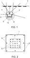
- the proposed system uses computer vision techniques to track the head of the user wearing a helmet (HMD) with a built-in camera to capture the images of the markers which are transmitted to a laptop through a USB 2.0 connector, the synchronisation between markers and camera not being necessary.
- HMD helmet
- a built-in camera to capture the images of the markers which are transmitted to a laptop through a USB 2.0 connector
- the system envisages two types of markers: secondary markers, consisting of 9 infrared LEDs, activated during the entire registration process, and primary markers, specifically 4 infrared LEDs, controlled to flash with a given coding pattern.
- the positioning system contemplated herein offers a completely satisfactory solution to the problem set out above, in the different aspects mentioned.
- the interaction space or absolute reference system can be divided, in plan view, into a series of sectors in order to cover the tracking area, in each of which a spatial module is established, located in the ceiling or suspended therefrom, as long as it is above the maximum height of the objects or users to be positioned, each module being a static element made of a square panel with pre-established dimensions, which integrates a set of LEDs adopting a certain configuration.
- the LEDs participating in these modules are differentiated into two types, on the one hand reference LEDs are defined, which emit light at a visible wavelength, and on the other hand identification LEDs are established, the wavelength of which is infrared, in order to hide the identification from the naked eye, such that the software enables the quick and simple distinction thereof.
- the reference LEDs are turned on in the same manner on all the panels, while the identification LEDs are turned on representing an identifier associated with the corresponding panel.
- the identification LEDs also enable the orientation of the panel and consequently the position of the user to be known.
- Each panel can be configured for any identifying element by means of an external element which communicates through an unpluggable connector.
- the panel can be a printed circuit board (PCB) wherein both the LEDs and the electronic components necessary for launching it are soldered.
- PCB printed circuit board
- Each panel is completely passive, such that once they receive power through a power connector, the LEDs turn on and continuously remain in this state.
- the second group of elements participating in the system of the invention are the tracking units, units which will be associated with each user or player and which consist of an independent element capable of recognising the LEDs of the panels in dim ambient lighting conditions.
- these tracking units incorporate a series of duly oriented cameras, associated with an embedded image processing unit, having a communications port and essential power supply means, whether they are batteries or wires.
- the tracking unit uses a single camera at any given time, and the system itself, according to the pose thereof, selects the most suitable camera such that it observes the largest number of spatial modules such that the plane of the nearest spatial module is as perpendicular as possible to the optical axis of the camera.
- the cameras are arranged such that each of the axes thereof points in a different direction, so that the field of vision of the assembly covers a wide field, keeping overlapping margins between them.
- This device can be wireless or not, when communicating with an element which uses the absolute position of the tracking unit in the reference system associated with the spatial modules, this element being conventional and therefore remaining outside the object of the present invention.
- the tracking unit through its own processing unit, calculates the relative position thereof based on the closest spatial modules identified by the cameras thereof.
- the sensor of the active camera obtains the image under a fixed parameter configuration, wherein a reduced exposure time is used in order to eliminate the noise from the ambient light, producing a clean image of the LEDs on an empty background.
- the image is then subdivided in order to be processed in portions in different threads of execution. Each of them locates the centres of the LEDs, which in the image are centred in pixel blobs and their coordinates are stored in the image plane. Once the portions have been processed, all the blobs are put together and classified into reference blobs and identification blobs.
- an embedded image processing system is used, without needing to send all the information to the PC, achieving low latency access to the image, an essential requirement for the viability of the system, sending only data structures encoded with the information necessary to obtain the pose of the tracking element.
- This embedded system enables, by means of a multiplexer, the connection from 1 to N cameras, covering the vision area required by each application, without this affecting the processing capacity.
- each of the tracking units sends the list of the located blobs to the equipment wherein the final calculation is performed by means of a communications interface either by local network or by Wi-Fi, if less latency is required.
- the processing of the information obtained by the tracking units can be carried out through the processing unit associated with them or in an external processing unit with greater power, through a communications network, such that in any of the cases in said processing process, the following operational phases will be carried out:
- the coordinates obtained by the image recognition algorithm are corrected by applying the distortion of the lens by means of a system which uses the intrinsic matrix of the camera and the distortion coefficients according to the model used.
- the identification algorithm is executed for each of the tracking units.
- the algorithm first locates the reference blobs, which enable it to project an internal grid on each panel. On this grid, it checks whether or not blobs fall into each of the squares thereof and the matrix associated to the panel is obtained. This matrix contains the orientation and the ID of the panel. In this manner, each of the real LEDs is able to be identified with the located blobs.
- the data of an IMU may or may not be obtained, in order to combine it with the data obtained from the optical system, since these sensors have a much higher refresh rate than the frames per second enabled by the camera.
- a filter is applied which combines the fusion of sensors between the data both from the optical system and the inertial system, as well as the past states thereof.
- the final result is obtaining the position in vector mode X, Y, Z and the orientation in quaternion representation X, Y, Z, W of each of the tracking units. This process is performed at a minimum of 40Hz and in an independent manner.
- the positioning system for virtual reality object of the invention is made up of two fundamental elements, a series of spatial modules (1) which are static and conveniently distributed on top of the operating surface and a series of tracking units (2), associated with each player or user.
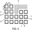
- the interaction space (3) or absolute reference system is divided, in plan view, into a series of equidistant and contiguous sectors or cells, in each of which a spatial module (1) is established, such that said modules are all arranged equidistantly, at a distance (d), adapting to the irregularities (4) in situ that said interaction space (3) may have.
- the spatial modules (1) are made of a square panel, wherein two groupings of LEDs of different types are integrated.
- a series of reference LEDs (5) and a series of identification LEDs (6) are established in said modules.
- the reference LEDs (5) emit light at a visible wavelength, while the identification LEDs (6) will emit at an infrared wavelength, such that the software enables the distinction thereof.
- the reference LEDs (5) are turned on in the same manner in all the panels, while the identification LEDs are turned on representing an identifier associated with the corresponding panel, likewise enabling the orientation of the panel and consequently the position of the user to be known.
- each panel or spatial module (1) can be configured for any identifying element by means of an external element which communicates through an unpluggable connector.
- the invention foresees the use of 8 LEDs in the visible range for positioning, and 16 infrared LEDs with a binary coding for identification, in addition to 6 infrared LEDs for correcting errors and accelerating the search algorithm.
- this solution is due to simple design criteria, such that the number of reference LEDs in the visible range could be reduced to 4 (never less than this), this distribution being optimal from the exclusive point of view of the panel, although it entails greater complexity in the recognition process, for which reason the participation of 8 LEDs has been chosen in the exemplary embodiment. As for the rest of the LEDs, the number thereof could also vary depending on different design criteria.
- the panel can be a printed circuit board (PCB) wherein both the LEDs and the electronic components necessary for launching it are soldered.
- PCB printed circuit board
- the tracking units (2) associated with each user or player consist of an independent element capable of recognising the LEDs (5-6) of the panels of each spatial module (1) in dim ambient lighting conditions.
- Said tracking units (2) incorporate a series of duly oriented cameras (7), associated with an image processing unit (8), having a communications port (9) and essential power supply means (10).
- the tracking unit (2) uses a single camera at any given time, and the system itself, according to the pose thereof, selects the most suitable camera such that it observes the largest number of spatial modules such that the plane of the nearest spatial module is perpendicular to the optical axis of the camera.
- the cameras (7) are arranged such that each of the axes thereof points in a different direction, so that the field of vision of the assembly covers a wide field, keeping overlapping margins between them.
- the tracking units (2) can be wireless or not, when communicating with virtual reality glasses or an element responsible for carrying out the generation of the images depending on the relative position within the reference system of each user, although the invention aims to be independent of the means with which said specific positional representations are eventually carried out, focusing exclusively on the system by means of which it is possible to carry out the positioning of the users of the system.
Landscapes
- Engineering & Computer Science (AREA)
- Multimedia (AREA)
- Human Computer Interaction (AREA)
- Physics & Mathematics (AREA)
- Theoretical Computer Science (AREA)
- General Engineering & Computer Science (AREA)
- General Physics & Mathematics (AREA)
- Remote Sensing (AREA)
- Radar, Positioning & Navigation (AREA)
- Electromagnetism (AREA)
- Software Systems (AREA)
- Computer Graphics (AREA)
- Computer Hardware Design (AREA)
- Automation & Control Theory (AREA)
- Heart & Thoracic Surgery (AREA)
- General Health & Medical Sciences (AREA)
- Cardiology (AREA)
- Biophysics (AREA)
- Life Sciences & Earth Sciences (AREA)
- Health & Medical Sciences (AREA)
- Length Measuring Devices By Optical Means (AREA)
- Image Analysis (AREA)
- Optical Communication System (AREA)
Applications Claiming Priority (2)
| Application Number | Priority Date | Filing Date | Title |
|---|---|---|---|
| ES201730883A ES2648643B2 (es) | 2017-07-04 | 2017-07-04 | Sistema de posicionamiento |
| PCT/ES2018/070435 WO2019008200A1 (es) | 2017-07-04 | 2018-06-20 | Sistema de posicionamiento |
Publications (2)
| Publication Number | Publication Date |
|---|---|
| EP3650996A1 true EP3650996A1 (de) | 2020-05-13 |
| EP3650996A4 EP3650996A4 (de) | 2020-05-13 |
Family
ID=60788742
Family Applications (1)
| Application Number | Title | Priority Date | Filing Date |
|---|---|---|---|
| EP18827559.8A Withdrawn EP3650996A4 (de) | 2017-07-04 | 2018-06-20 | Positionierungssystem |
Country Status (7)
| Country | Link |
|---|---|
| US (1) | US11169596B2 (de) |
| EP (1) | EP3650996A4 (de) |
| CN (1) | CN110809748A (de) |
| CA (1) | CA3064672A1 (de) |
| ES (1) | ES2648643B2 (de) |
| MX (1) | MX2019014856A (de) |
| WO (1) | WO2019008200A1 (de) |
Families Citing this family (3)
| Publication number | Priority date | Publication date | Assignee | Title |
|---|---|---|---|---|
| CN113093105B (zh) * | 2021-04-09 | 2023-09-12 | 中国人民解放军战略支援部队信息工程大学 | 可见光室内定位方法、装置、系统及相关产品 |
| CN115560735B (zh) * | 2022-08-26 | 2024-10-29 | 中国长江三峡集团有限公司 | 一种用于隧洞设备移动定位的复合标靶系统及定位方法 |
| CN117891063A (zh) * | 2022-10-08 | 2024-04-16 | 北京字跳网络技术有限公司 | 光学跟踪器的定位方法、装置及系统 |
Family Cites Families (8)
| Publication number | Priority date | Publication date | Assignee | Title |
|---|---|---|---|---|
| US7129929B1 (en) * | 2003-03-07 | 2006-10-31 | Microsoft Corporation | Computer input device with multi-purpose light guide |
| JP4418935B2 (ja) | 2004-07-15 | 2010-02-24 | 株式会社国際電気通信基礎技術研究所 | 光学マーカシステム |
| DE102005013225A1 (de) * | 2005-03-18 | 2006-09-28 | Fluyds Gmbh | Objektverfolgungs- und Situationsanalysesystem |
| GB2504890A (en) * | 2011-04-15 | 2014-02-12 | Faro Tech Inc | Enhanced position detector in laser tracker |
| CN106152937B (zh) * | 2015-03-31 | 2019-10-25 | 深圳超多维科技有限公司 | 空间定位装置、系统及其方法 |
| US20160379074A1 (en) * | 2015-06-25 | 2016-12-29 | Appropolis Inc. | System and a method for tracking mobile objects using cameras and tag devices |
| CN105353347B (zh) * | 2015-10-30 | 2017-10-10 | 中国地质大学(武汉) | 一种基于led照明的室内定位导航方法及装置 |
| CN205229572U (zh) * | 2015-12-27 | 2016-05-11 | 深圳游视虚拟现实技术有限公司 | 基于标记点的多目标实时定位追踪装置及虚拟现实系统 |
-
2017
- 2017-07-04 ES ES201730883A patent/ES2648643B2/es not_active Expired - Fee Related
-
2018
- 2018-06-20 US US16/624,529 patent/US11169596B2/en not_active Expired - Fee Related
- 2018-06-20 WO PCT/ES2018/070435 patent/WO2019008200A1/es not_active Ceased
- 2018-06-20 EP EP18827559.8A patent/EP3650996A4/de not_active Withdrawn
- 2018-06-20 CA CA3064672A patent/CA3064672A1/en active Pending
- 2018-06-20 CN CN201880043962.1A patent/CN110809748A/zh not_active Withdrawn
- 2018-06-20 MX MX2019014856A patent/MX2019014856A/es unknown
Also Published As
| Publication number | Publication date |
|---|---|
| ES2648643A1 (es) | 2018-01-04 |
| WO2019008200A1 (es) | 2019-01-10 |
| MX2019014856A (es) | 2020-02-12 |
| US20210149477A1 (en) | 2021-05-20 |
| CN110809748A (zh) | 2020-02-18 |
| ES2648643B2 (es) | 2018-07-25 |
| CA3064672A1 (en) | 2019-01-10 |
| EP3650996A4 (de) | 2020-05-13 |
| US11169596B2 (en) | 2021-11-09 |
Similar Documents
| Publication | Publication Date | Title |
|---|---|---|
| US10666929B2 (en) | Hardware system for inverse graphics capture | |
| US11010911B1 (en) | Multi-channel depth estimation using census transforms | |
| CN110572630B (zh) | 三维图像拍摄系统、方法、装置、设备以及存储介质 | |
| JP6821714B2 (ja) | 改良されたカメラ較正システム、標的、およびプロセス | |
| US8897502B2 (en) | Calibration for stereoscopic capture system | |
| US10044922B1 (en) | Hardware system for inverse graphics capture | |
| US11169596B2 (en) | Positioning system | |
| CN114549651B (zh) | 一种基于多面体几何约束的多个3d相机标定方法和设备 | |
| US20110169922A1 (en) | Three dimension model building system and method | |
| CN110910460A (zh) | 一种获取位置信息的方法、装置及标定设备 | |
| CN110119190A (zh) | 定位方法、装置、识别跟踪系统及计算机可读介质 | |
| CN110119194A (zh) | 虚拟场景处理方法、装置、交互系统、头戴显示装置、视觉交互装置及计算机可读介质 | |
| CN115272466A (zh) | 手眼标定方法、视觉机器人、手眼标定设备和存储介质 | |
| US10666925B2 (en) | Stereoscopic calibration using a multi-planar calibration target | |
| CN103546680B (zh) | 一种无变形的全方位鱼眼摄像装置及实现方法 | |
| CN108119780A (zh) | 一种自由视角变光照图像采集系统 | |
| CN105447007B (zh) | 一种电子设备及数据处理方法 | |
| WO2025000684A1 (en) | Human body positioning method based on multi-perspectives and lighting system | |
| CN118337981A (zh) | 体积视频生成系统和体积视频生成方法 | |
| CN113834638B (zh) | 视场角确定方法、装置、设备及存储介质 | |
| US9633279B2 (en) | Free space positioning method and system | |
| CN110120060B (zh) | 标记物的识别方法、装置及识别跟踪系统 | |
| Holter et al. | Relative visual localization for unmanned aerial systems | |
| CN113538588A (zh) | 标定方法、标定装置及应用其的电子设备 | |
| CN101165719A (zh) | 一种基于标志点的增强实现工业维修方法及系统 |
Legal Events
| Date | Code | Title | Description |
|---|---|---|---|
| STAA | Information on the status of an ep patent application or granted ep patent |
Free format text: STATUS: THE INTERNATIONAL PUBLICATION HAS BEEN MADE |
|
| PUAI | Public reference made under article 153(3) epc to a published international application that has entered the european phase |
Free format text: ORIGINAL CODE: 0009012 |
|
| STAA | Information on the status of an ep patent application or granted ep patent |
Free format text: STATUS: REQUEST FOR EXAMINATION WAS MADE |
|
| 17P | Request for examination filed |
Effective date: 20191202 |
|
| A4 | Supplementary search report drawn up and despatched |
Effective date: 20200415 |
|
| AK | Designated contracting states |
Kind code of ref document: A1 Designated state(s): AL AT BE BG CH CY CZ DE DK EE ES FI FR GB GR HR HU IE IS IT LI LT LU LV MC MK MT NL NO PL PT RO RS SE SI SK SM TR |
|
| AX | Request for extension of the european patent |
Extension state: BA ME |
|
| DAV | Request for validation of the european patent (deleted) | ||
| DAX | Request for extension of the european patent (deleted) | ||
| STAA | Information on the status of an ep patent application or granted ep patent |
Free format text: STATUS: EXAMINATION IS IN PROGRESS |
|
| 17Q | First examination report despatched |
Effective date: 20210322 |
|
| STAA | Information on the status of an ep patent application or granted ep patent |
Free format text: STATUS: THE APPLICATION IS DEEMED TO BE WITHDRAWN |
|
| 18D | Application deemed to be withdrawn |
Effective date: 20240103 |