EP3650752A1 - Lamp assembly for textiles - Google Patents
Lamp assembly for textiles Download PDFInfo
- Publication number
- EP3650752A1 EP3650752A1 EP19165393.0A EP19165393A EP3650752A1 EP 3650752 A1 EP3650752 A1 EP 3650752A1 EP 19165393 A EP19165393 A EP 19165393A EP 3650752 A1 EP3650752 A1 EP 3650752A1
- Authority
- EP
- European Patent Office
- Prior art keywords
- light
- textile
- light guide
- arrangement according
- luminaire arrangement
- Prior art date
- Legal status (The legal status is an assumption and is not a legal conclusion. Google has not performed a legal analysis and makes no representation as to the accuracy of the status listed.)
- Withdrawn
Links
Images


Classifications
-
- F—MECHANICAL ENGINEERING; LIGHTING; HEATING; WEAPONS; BLASTING
- F21—LIGHTING
- F21V—FUNCTIONAL FEATURES OR DETAILS OF LIGHTING DEVICES OR SYSTEMS THEREOF; STRUCTURAL COMBINATIONS OF LIGHTING DEVICES WITH OTHER ARTICLES, NOT OTHERWISE PROVIDED FOR
- F21V33/00—Structural combinations of lighting devices with other articles, not otherwise provided for
- F21V33/0004—Personal or domestic articles
- F21V33/0008—Clothing or clothing accessories, e.g. scarfs, gloves or belts
-
- F—MECHANICAL ENGINEERING; LIGHTING; HEATING; WEAPONS; BLASTING
- F21—LIGHTING
- F21S—NON-PORTABLE LIGHTING DEVICES; SYSTEMS THEREOF; VEHICLE LIGHTING DEVICES SPECIALLY ADAPTED FOR VEHICLE EXTERIORS
- F21S9/00—Lighting devices with a built-in power supply; Systems employing lighting devices with a built-in power supply
- F21S9/02—Lighting devices with a built-in power supply; Systems employing lighting devices with a built-in power supply the power supply being a battery or accumulator
-
- G—PHYSICS
- G02—OPTICS
- G02B—OPTICAL ELEMENTS, SYSTEMS OR APPARATUS
- G02B6/00—Light guides; Structural details of arrangements comprising light guides and other optical elements, e.g. couplings
- G02B6/0001—Light guides; Structural details of arrangements comprising light guides and other optical elements, e.g. couplings specially adapted for lighting devices or systems
- G02B6/0005—Light guides; Structural details of arrangements comprising light guides and other optical elements, e.g. couplings specially adapted for lighting devices or systems the light guides being of the fibre type
- G02B6/001—Light guides; Structural details of arrangements comprising light guides and other optical elements, e.g. couplings specially adapted for lighting devices or systems the light guides being of the fibre type the light being emitted along at least a portion of the lateral surface of the fibre
-
- F—MECHANICAL ENGINEERING; LIGHTING; HEATING; WEAPONS; BLASTING
- F21—LIGHTING
- F21Y—INDEXING SCHEME ASSOCIATED WITH SUBCLASSES F21K, F21L, F21S and F21V, RELATING TO THE FORM OR THE KIND OF THE LIGHT SOURCES OR OF THE COLOUR OF THE LIGHT EMITTED
- F21Y2115/00—Light-generating elements of semiconductor light sources
- F21Y2115/10—Light-emitting diodes [LED]
-
- G—PHYSICS
- G02—OPTICS
- G02B—OPTICAL ELEMENTS, SYSTEMS OR APPARATUS
- G02B6/00—Light guides; Structural details of arrangements comprising light guides and other optical elements, e.g. couplings
- G02B6/0001—Light guides; Structural details of arrangements comprising light guides and other optical elements, e.g. couplings specially adapted for lighting devices or systems
- G02B6/0005—Light guides; Structural details of arrangements comprising light guides and other optical elements, e.g. couplings specially adapted for lighting devices or systems the light guides being of the fibre type
- G02B6/0006—Coupling light into the fibre
Abstract
Eine Leuchtenanordnung für Textilien (10; 100) enthält eine Vorrichtung (42) zur Erzeugung eines Lichtstrahls; eine Lichtleiteranordnung (12, 16; 14, 18) mit wenigstens einem in das Textil (10; 100) integrierbaren Lichtleiter (12; 14); einen Koppler (36, 38) zum Einkoppeln des Lichtstrahls in den Lichtleiter (16, 18); wobei die Lichtleiteranordnung (12, 16; 14, 18) zumindest einen als Seitenlichtfaser ausgebildeten Lichtleiter (12, 14) umfasst, der das eingekoppelte Licht in radialer Richtung abstrahlt.A lamp arrangement for textiles (10; 100) contains a device (42) for generating a light beam; a light guide arrangement (12, 16; 14, 18) with at least one light guide (12; 14) that can be integrated into the textile (10; 100); a coupler (36, 38) for coupling the light beam into the light guide (16, 18); wherein the light guide arrangement (12, 16; 14, 18) comprises at least one light guide (12, 14) designed as a side light fiber, which radiates the injected light in the radial direction.
Description
Die Erfindung betrifft eine Leuchtenanordnung für Textilien.The invention relates to a lamp arrangement for textiles.
Unter dem Begriff "intelligente Textilien" (smart textiles, smart cloths, I-cloths) ist eine Vielzahl von Textilien bekannt, die über den Sichtschutz und die Isolierung des Körpers hinaus funktionelle und elektronische Eigenschaften haben. Üblicherweise werden metallische Garne als elektrische Leiter in Gewebe eingewebt oder aufgestickt. Diese übertragen elektrische Signale an einen ebenfalls in das Textil integrierten Verbraucher. Ein Beispiel für bekannte Verbraucher sind Sensoren, welche Körperfunktionen aufnehmen.
Es gibt Gürtel oder Armbänder, an denen batteriebetriebene Bänder mit LED-Leuchten befestigt sind. Diese dienen der besseren Sichtbarkeit, beispielsweise im Straßenverkehr.There are belts or bracelets to which battery-operated belts with LED lights are attached. These serve to improve visibility, for example in road traffic.
Nachteilig bei bekannten intelligenten Textilien ist es, dass die metallischen Leiter beim Waschen oder anderweitigen Kontakt mit Flüssigkeiten (z. B. Schweiß) korrodieren. Dann ist die Funktionsfähigkeit nicht mehr gegeben. Außerdem beeinträchtigen Oxide die Optik.A disadvantage of known intelligent textiles is that the metallic conductors corrode when washed or otherwise come into contact with liquids (e.g. sweat). Then the functionality is no longer given. In addition, oxides impair the optics.
Typischerweise haben Textilhersteller keine oder nur wenig Erfahrung mit Elektronikbauteilen. Die Herstellung von intelligenten Textilien erfordert daher zusätzliche Kenntnisse, Werkzeuge und Maschinen für die Herstellung der elektronischen Eigenschaften des Textils.Typically, textile manufacturers have little or no experience with electronic components. The production of intelligent textiles therefore requires additional knowledge, tools and machines for the production of the electronic properties of the textile.
Es ist Aufgabe der Erfindung, eine Leuchtenanordnung für Textilien zu schaffen, welche die Trennung der Elektronikherstellung von der Textilherstellung ermöglicht. Erfindungsgemäß wird die Aufgabe mit einer Leuchtenanordnung für Textilien gelöst, enthaltend:
- (a) eine Vorrichtung zur Erzeugung eines Lichtstrahls;
- (b) eine Lichtleiteranordnung mit wenigstens einem in das Textil integrierbaren Lichtleiter;
- (c) einen Koppler zum Einkoppeln des Lichtstrahls in den Lichtleiter; wobei
- (d) die Lichtleiteranordnung zumindest einen als Seitenlichtfaser ausgebildeten Lichtleiter umfasst, der das eingekoppelte Licht in radialer Richtung abstrahlt.
- (a) an apparatus for generating a light beam;
- (b) a light guide arrangement with at least one light guide that can be integrated into the textile;
- (c) a coupler for coupling the light beam into the light guide; in which
- (d) the light guide arrangement comprises at least one light guide designed as a side light fiber, which radiates the injected light in the radial direction.
Unter einer Lichtleiteranordnung wird hier eine Anordnung mit nur einem oder auch mehreren, aneinander gekoppelten Lichtleitern verstanden. Die Lichtleiter können seriell aneinander gekoppelt sein oder zumindest abschnittsweise mittels eines Switches aufgeteilt sein. Ein Textil besteht aus Garnen oder Fäden, die zu einem Gewebe, Gestrick, oder Geflecht verarbeitet oder auf andere Weise zu einem zweidimensionalen Material vereint sind. Die Garne können natürlicher Herkunft, wie Baumwolle oder Wolle sein oder aus Kunststoff, etwa Polyester, Polyamid oder dergleichen hergestellt sein oder ein Gemisch daraus bilden.An optical fiber arrangement is understood here to mean an arrangement with only one or also a plurality of optical fibers coupled to one another. The light guides can be coupled to one another in series or at least partially divided by means of a switch. A textile consists of yarns or threads that are processed into a fabric, knitted fabric, or braid, or are combined in another way to form a two-dimensional material. The yarns can be of natural origin, such as cotton or wool, or can be made of plastic, such as polyester, polyamide or the like, or they can form a mixture thereof.
Bei der erfindungsgemäßen Anordnung braucht nur der Lichtleiter in das Textil integriert werden. Die elektronischen Komponenten können vollständig separat hergestellt werden. Die Maschinen zur Herstellung des Textils bleiben unverändert. Bei der vorliegenden Erfindung ist vorgesehen, dass die Lichtleiteranordnung einen Abschnitt hat, der als Seitenlichtfaser ausgebildet ist. Dort kann Licht seitlich austreten. In mindestens einem der Bereiche, wo die Seitenlichtfaser in das Textil integriert ist, leuchtet das Textil. Wenn kein Licht in den Lichtleiter eingekoppelt wird, ist der Lichtleiter unscheinbar und tritt im Erscheinungsbild gegenüber weiteren Fäden oder Garnen des Textils zurück.In the arrangement according to the invention, only the light guide needs to be integrated into the textile. The electronic components can be manufactured completely separately. The machines for manufacturing the textile remain unchanged. In the present The invention provides that the light guide arrangement has a section which is designed as a side light fiber. There, light can emerge from the side. The textile glows in at least one of the areas where the side light fiber is integrated into the textile. If no light is coupled into the light guide, the light guide is inconspicuous and the appearance of other threads or yarns of the textile is reduced.
Wenn das Textil dekorativen Zwecken dient oder als stationäre Sicherheitseinrichtung, kann der Lichtstrahl in einem an das Stromnetz angeschlossenen Treiber erzeugt werden und mittels Koppler in den Lichtleiter eingekoppelt werden. Bei mobilen Textilien, wie beispielsweise Kleidungsstücken, Bändern, Rucksäcken oder Taschen ist es vorteilhaft, wenn vorgesehen ist, dass die Vorrichtung zur Erzeugung eines Lichtstrahls einen Energiespeicher umfasst und einen Treiber zum Umwandeln der gespeicherten Energie in Licht. Energiespeicher können beispielsweise von wiederaufladbaren Akkumulatoren, Batterien oder chemischen Energiespeichern gebildet sein. Auch Solarzellen können mit oder ohne Akkumulator verwendet werden. Die Energie kann im Treiber, beispielsweise mittels einer LED oder eines Lasers in Licht umgewandelt werden. Vorteilhafterweise ist vorgesehen, dass der Energiespeicher lösbar mit dem Textil verbunden ist. Dies kann beispielsweise durch Aufnahme in einer Tasche oder Befestigen mittels Riemen oder Band erfolgen. Die lösbare Verbindung erleichtert den Austausch oder das Aufladen des Energiespeichers. Außerdem braucht der Energiespeicher nicht mitgewaschen werden.If the textile is used for decorative purposes or as a stationary safety device, the light beam can be generated in a driver connected to the power supply and can be coupled into the light guide using a coupler. In the case of mobile textiles, such as items of clothing, tapes, backpacks or bags, it is advantageous if it is provided that the device for generating a light beam comprises an energy store and a driver for converting the stored energy into light. Energy stores can be formed, for example, by rechargeable batteries, batteries or chemical energy stores. Solar cells can also be used with or without an accumulator. The energy can be converted into light in the driver, for example by means of an LED or a laser. It is advantageously provided that the energy store is detachably connected to the textile. This can be done, for example, by taking it in a pocket or fastening it with a strap or tape. The detachable connection facilitates the exchange or charging of the energy store. In addition, the energy store does not need to be washed.
Der Lichtstrahl wird über einen Koppler in den ersten treiberseitigen Lichtleiter der Lichtleiteranordnung eingekoppelt. Es ist möglich, den Koppler zum Waschen von dem Lichtleiter in dem Textil zu trennen. Beim Koppeln ist jedoch eine genaue Justierung erforderlich. Dies ist für den Laien in der Regel schwierig. Es ist daher vorteilhafterweise vorgesehen, dass der Koppler in das Textil integriert ist und waschbar ausgebildet oder in einer waschbaren Hülle angeordnet ist. Beispielsweise kann der Koppler mit dem Treiber in einer wasserdichten Hülle vorgesehen sein. Es ist aber auch möglich, den Koppler und den Treiber in ein Silikonharz zu gießen, so dass Wasser, Hitze, Dreck und andere Umwelteinflüsse abgeschirmt werden. Die Kopplung erfolgt dann werksseitig durch Fachleute. Die so geschützten, elektronischen und optischen Bauelemente können in einer geschlossenen Tasche oder anderen Aufnahme des Textils aufgenommen sein, wo sie während des Waschvorgangs verbleiben können.The light beam is coupled into the first driver-side light guide of the light guide arrangement via a coupler. It is possible to separate the coupler for washing from the light guide in the textile. However, precise adjustment is required when coupling. This is usually difficult for the layperson. It is therefore advantageously provided that the coupler is integrated in the textile and is designed to be washable or arranged in a washable envelope. For example, the coupler with the driver can be provided in a waterproof casing. However, it is also possible to cast the coupler and the driver in a silicone resin so that water, heat, dirt and other environmental influences are shielded. The coupling is then carried out by experts at the factory. The electronic and optical components protected in this way can be accommodated in a closed pocket or other receptacle of the textile, where they can remain during the washing process.
Vorteilhafterweise ist vorgesehen, dass der Lichtleiter zumindest einen Abschnitt aufweist, in dem kein Licht in radialer Richtung abgestrahlt wird. Das Licht wird dann vom Koppler durch eine Endlichtfaser bis zu der Stelle überführt, an der die Abstrahlung erwünscht und vorgesehen ist. Die Endlichtfaser ist von außen unauffällig. Sie ermöglicht es, dass elektronische und optische Komponenten an einer geeigneten Stelle des Textils oder außerhalb des Textils in einer Entfernung des abstrahlenden Bereichs untergebracht werden. Statt Strom über elektrische Leitungen wird Licht über die Endlichtfaser in das Textil oder an eine andere Stelle im Textil überführt. Die textile Optik bleibt an allen Stellen erhalten.It is advantageously provided that the light guide has at least one section in which no light is emitted in the radial direction. The coupler then transmits the light through an end light fiber to the point at which the radiation is desired and intended. The end light fiber is inconspicuous from the outside. It enables electronic and optical components to be accommodated at a suitable location on the textile or outside the textile at a distance from the radiating area. Instead of electricity via electrical lines, light is transferred to the textile or to another location in the textile via the end light fiber. The textile look is retained at all points.
Der Lichtleiter kann in das Textil eingestrickt, aufgestickt oder eingewebt sein. Er bildet dann einen Teil des Textils und kann sich auch beim Waschen nicht ohne Weiteres lösen.The light guide can be knitted, embroidered or woven into the textile. It then forms part of the textile and cannot easily detach even during washing.
Bei einer weiteren Ausgestaltung der Erfindung ist der Treiber fernsteuerbar ausgebildet. Dann ist kein Schalter oder dergleichen an dem Textil selber erforderlich. Insbesondere, wenn der Treiber beim Einsatz schwer erreichbar ist, erleichtert die Fernsteuerung das An- und Ausschalten der Leuchtenanordnung und anderweitige Steuerung. Eine Fernsteuerung erlaubt auch eine komplexere Steuerung, als dies am Treiber vorgesehen sein kann. Dimmen, Blinken, Zeitsteuerung und dergleichen können in einem eigenen Gerät verwirklicht werden.In a further embodiment of the invention, the driver is designed to be remotely controllable. Then no switch or the like is required on the textile itself. In particular, if the driver is difficult to reach during use, the remote control makes it easier to switch the luminaire arrangement on and off and other controls. Remote control also allows more complex control than can be provided on the driver. Dimming, flashing, time control and the like can be implemented in a separate device.
Vorzugsweise weist der Treiber eine Steuerelektronik mit einem Empfänger auf und die Fernsteuerung erfolgt mit einem mobilen Endgerät, welches Signale über eine Drahtlosverbindung an den Empfänger sendet. Die Drahtlosverbindung kann direkt, beispielsweise über Bluetooth, Infrarot, NIR und dergleichen verwirklicht werden. Es ist aber auch möglich, eine Verbindung über ein Netzwerk, etwa WLAN, DLNA, Internet oder dergleichen herzustellen. Dies ist insbesondere dann sinnvoll, wenn die Steuerung über ein Mobilfunkendgerät, wie beispielsweise ein Smartphone erfolgen soll. Die Fernsteuerung ist insbesondere sinnvoll, wenn die Steuerung mittels textiler Taster, beispielsweise über einen Handschuh oder ein Armband erfolgt. Dieser muss dann nicht zwingend im gleichen Textil verwirklicht sein, wie die in ein Textil integrierte Leuchtenanordnung. Auch Steuergeräte am Lenkrad eines Fahrrads oder vergleichbaren Fahrzeugs können zur Fernsteuerung vorgesehen sein.The driver preferably has control electronics with a receiver, and remote control takes place with a mobile terminal which sends signals to the receiver via a wireless connection. The wireless connection can be implemented directly, for example via Bluetooth, infrared, NIR and the like. However, it is also possible to establish a connection via a network, for example WLAN, DLNA, Internet or the like. This is particularly useful if control is to be carried out via a mobile radio terminal, such as a smartphone. The remote control is particularly useful if the control is carried out by means of textile buttons, for example using a glove or a bracelet. This then does not necessarily have to be realized in the same textile as that integrated in a textile Luminaire arrangement. Control devices on the steering wheel of a bicycle or comparable vehicle can also be provided for remote control.
Bei einer alternativen Ausgestaltung der Erfindung ist vorgesehen, dass das Textil wenigstens einen Grundfaden, wenigstens einen Lichtleiter und wenigstens einen thermoplastischen Faden aufweist und durch Wärmebehandlung versteift ist. Ein Lichtleiter aus Kunststoff wird bei Wärmebehandlung steif. Die Versteifung kann aber auch zusätzlich oder alternativ dadurch erreicht werden, dass ein thermoplastischer Faden in das Textil integriert werden. Dies kann beispielsweise durch einen weiteren Faden (Plattierfaden) im Gestrick oder durch eine Schussfaden im Gewebe verwirklicht werden. Der Plattierfaden kann im Strickprozess gleichzeitig mit dem Grundfaden in das Textil eingebracht werden. Er legt dann den gleichen Weg zurück, wie der Grundfaden.In an alternative embodiment of the invention it is provided that the textile has at least one basic thread, at least one light guide and at least one thermoplastic thread and is stiffened by heat treatment. A plastic light guide becomes stiff during heat treatment. The stiffening can also be achieved additionally or alternatively by integrating a thermoplastic thread into the textile. This can be achieved, for example, by a further thread (cladding thread) in the knitted fabric or by a weft thread in the fabric. The cladding thread can be introduced into the textile at the same time as the basic thread in the knitting process. He then travels the same way as the basic thread.
Das flexible Textil wird warm gepresst. Die erforderlichen Temperaturen hängen von der Natur des thermoplastischen Fadens ab. Bei typischen thermoplastischen Materialien ist beispielsweise ein Temperaturbereich zwischen 60°C und 200°C sinnvoll. Das Verpressen kann je nach Einsatzzweck in zweidimensionalen und dreidimensionalen, beheizte Pressformen erfolgen. Dadurch können leuchtende Dekorationsobjekte, Wohnaccessoirs, Lampenschirme, Sicherheitseinrichtungen und dergleichen mehr mit textiler Optik erzeugt werden. Die Maschinen müssen nicht geändert werden.The flexible textile is pressed warm. The temperatures required depend on the nature of the thermoplastic thread. For typical thermoplastic materials, for example, a temperature range between 60 ° C and 200 ° C is useful. Depending on the application, pressing can take place in two-dimensional and three-dimensional, heated molds. As a result, luminous decorative objects, home accessories, lampshades, safety devices and the like can be produced with textile optics. The machines do not have to be changed.
Bei einer besonders vorteilhaften Ausgestaltung der Erfindung ist vorgesehen, dass der Lichtstrahl auf mehrere Lichtleiter verteilt wird. Hierzu kann ein Splitter verwendet werden. Um einen Lichtleiter mit einer hohen Flexibilität im Textil zu verarbeiten, ist es sinnvoll, wenn der Durchmesser des Lichtleiters gering ist. Umgekehrt ist es einfacher, wenn das Licht in einem oder nur wenigen Lichtleitern zur leuchtenden Stelle geführt wird. Entsprechend kann der eine Lichtleiter einen größeren Durchmesser haben, als der Abschnitt mit der Seitenlichtfaser.In a particularly advantageous embodiment of the invention, it is provided that the light beam is distributed over several light guides. A splitter can be used for this. In order to process a light guide with a high flexibility in the textile, it makes sense if the diameter of the light guide is small. Conversely, it is easier if the light is guided to the shining point in one or only a few light guides. Accordingly, the one light guide can have a larger diameter than the section with the side light fiber.
Bei einer vorteilhaften Ausgestaltung der Erfindung ist vorgesehen, dass die Lichtleiteranordnung einen an den Treiber gekoppelten Abschnitt aufweist, welcher von einer Endlichtfaser gebildet ist, und wenigstens einen Abschnitt, welcher von wenigstens einer Seitenlichtfaser gebildet ist und die Abschnitte mittels Koppler verbunden sind.In an advantageous embodiment of the invention, it is provided that the light guide arrangement has a section coupled to the driver, which is formed by a final light fiber, and at least one section, which is formed by at least one side light fiber, and the sections are connected by means of couplers.
Zur Verwirklichung eines Blinkersystems für Fahrzeuge, etwa für Fahrräder, sind wenigstens zwei Taster vorgesehen sind, mit denen die Leuchtenanordnung ansteuerbar ist. Die Leuchtenanordnung umfasst dabei beispielsweise wenigstens zwei leuchtende Abschnitte aus Seitenlichtfasern. Mit einem Abschnitt wird die Richtung "links" angezeigt. Mit einem anderen Abschnitt wird die Richtung "rechts" angezeigt. Die Seitenlichtfasern können in eine Fahrradjacke, in eine Weste, einen Gürtel oder in einen Rucksack integriert sein, so dass sie von hinten und/oder von der Seite gut sichtbar sind. Die Betätigung erfolgt verdrahtet oder drahtlos über Signalgeber im Hand- oder Lenkerbereich. Es versteht sich, dass zusätzlich zu dem Blinkersystem oder anstelle dessen auch dauerleuchtende, oder aufleuchtende Seitenlichtfasern vorgesehen sein können, die lediglich ein- und ausgeschaltet werden. Diese dienen der besseren Sichtbarkeit des Nutzers.In order to implement a turn signal system for vehicles, for example for bicycles, at least two buttons are provided with which the lamp arrangement can be controlled. The luminaire arrangement comprises, for example, at least two luminous sections made of side light fibers. A section shows the direction "left". Another section shows the direction "right". The side light fibers can be integrated into a cycling jacket, a vest, a belt or a backpack so that they are clearly visible from the rear and / or from the side. The actuation is wired or wireless via signal transmitters in the hand or handlebar area. It goes without saying that in addition to or instead of the turn signal system, continuously illuminating or illuminating side light fibers can also be provided, which are only switched on and off. These serve to improve the visibility of the user.
Ausgestaltungen der Erfindung sind Gegenstand der Unteransprüche. Ein Ausführungsbeispiel ist nachstehend unter Bezugnahme auf die beigefügten Zeichnungen näher erläutert.Embodiments of the invention are the subject of the dependent claims. An embodiment is explained below with reference to the accompanying drawings.
- Fig.1Fig. 1
- illustriert schematisch die Komponenten für eine ferngesteuerte Lichtleiteranordnung mit einer in ein Textil integrierten Seitenlichtfaser.schematically illustrates the components for a remote-controlled light guide arrangement with a side light fiber integrated into a textile.
- Fig.2Fig. 2
-
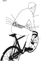
illustriert die Verwendung der Lichtleiteranordnung aus
Figur 1 als Blinkersystem in einer Jacke.illustrates the use of the light guide assemblyFigure 1 as a turn signal system in a jacket. - Fig.3Fig. 3
-
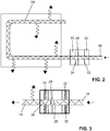
zeigt die Komponenten eines Treibers für die Anordnung aus
Figur 1 mit Energieversorgung und Koppler im Detail.shows the components of a driver for the arrayFigure 1 with power supply and coupler in detail. - Fig.4Fig. 4
- illustriert einen einfachen Aufbau einer Lichtleiteranordnung mit einem Abschnitt mit einer Seitenlichtfaser und einem Abschnitt mit einer Endlichtfaser.illustrates a simple construction of an optical fiber arrangement with a section with a side light fiber and a section with a final light fiber.
- Fig.5Fig. 5
- zeigt einen Teil einer Lichtleiteranordnung, bei dem das von einer Endlichtfaser mit größerem Durchmesser kommende Licht auf drei Seitenlichtfasern mit geringerem Durchmesser aufgeteilt wird.shows part of an optical fiber arrangement, in which the light coming from a final light fiber with a larger diameter is divided into three side light fibers with a smaller diameter.
- Fig.6Fig. 6
- illustriert die Verteilung des Lichts auf mehrere Seitenlichtfasern.illustrates the distribution of light across multiple side light fibers.
- Fig.7Fig. 7
- illustriert die Lage eines Lichtleiters in einem Gestrick.illustrates the position of a light guide in a knitted fabric.
- Fig.8Fig. 8
- zeigt einige Maschen eines Gestricks aus einem Grundfaden und einem Plattierfaden mit einem integrierten Lichtleiter.shows some stitches of a knitted fabric from a basic thread and a cladding thread with an integrated light guide.
- Fig.9Fig. 9
- illustriert das Pressen eines Textils zu einem dreidimensionalen Körper.illustrates the pressing of a textile into a three-dimensional body.
- Fig. 10Fig. 10
- zeigt einen Fahrradfahrer mit einem vom Lenker aus ferngesteuerten Blinker in Form eines Gürtels.shows a cyclist with a turn signal remotely controlled from the handlebar in the form of a belt.
- Fig.11Fig. 11
-
ist eine schematische Darstellung des Gürtels aus
Figur 10 im Detail.is a schematic representation of the belt fromFigure 10 in detail. - Fig.12Fig. 12
-
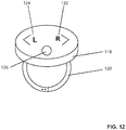
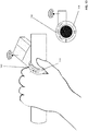
zeigt die Fernsteuerung aus
Figur 10 im Detail.shows the remote controlFigure 10 in detail. - Fig.13Fig. 13
-
illustriert eine alternative Ausgestaltung einer Fernsteuerung für den Gürtel aus
Figur 11 .illustrates an alternative embodiment of a remote control for the beltFigure 11 .
In die Jacke sind zwei dünne Seitenlichtfasern 12 und 14 eingestrickt. Eine Seitenlichtfaser ist ein Lichtwellenleiter, dessen Mantel in der Weise ausgebildet ist, dass ein Teil des Lichts in radialer Richtung aus dem Lichtwellenleiter austreten kann. Ein anderer Teil des Lichts wird am Mantel reflektiert und weitergeleitet. Beispiele für Seitenlichtfasern sind Seitenlicht - Polymeroptische Fasern, die auch mit SL POF abgekürzt werden. Die Seitenlichtfaser 12 erstreckt sich nach rechts in
An die Seitenlichtfasern 12 und 14 ist jeweils eine Endlichtfaser 16 bzw. 18 gekoppelt. Eine Endlichtfaser ist ein Lichtwellenleiter, in welchem das Licht durchgängig reflektiert oder totalreflektiert wird. Entsprechend tritt kein Licht in radialer Richtung aus. Das Licht wird, bis auf immer vorhandene Verluste durch beispielsweise Absorption, vollständig zum Austrittsende der Faser geleitet.
Zur Herstellung der Verbindung zwischen Seitenlichtfaser und Endlichtfaser sind Koppler 20 und 22 vorgesehen. Hier ist praktisch jede Art von Koppler geeignet. Es können Steckverbindungen, etwa Linsensteckverbinder oder Kontaktsteckverbinder eingesetzt werden. Die Koppler sind in
Die Seitenlichtfasern 12 und 14, die Koppler 20 und 22 und die Endlichtfasern 16 und 18 bilden eine Lichtleiteranordnung mit aneinander gekoppelten Abschnitten 12 und 16 bzw. 14 und 18. Es ist aber auch möglich, die Abschnitte ohne gesonderte Koppler durch entsprechende Ausgestaltung des Fasermantels zu erzeugen. In einigen Abschnitten erlaubt der Fasermantel einen seitlichen Austritt des Lichts, während das durch den Lichtleiter geleitete Licht in anderen Abschnitten vollständig reflektiert wird und nicht austreten kann.The
Im vorliegenden Ausführungsbeispiel wird das Licht über die Endlichtfasern 16 und 18 von außen nicht wahrnehmbar zu den aus den Seitenlichtlichtfasem 12 und 14 gebildeten Abschnitten geleitet. Alle Abschnitte sind im vorliegenden Ausführungsbeispiel in das Gestrick eingestrickt. Dadurch wird die textile Optik des Gestricks nicht beeinträchtigt.In the present exemplary embodiment, the light is guided via the
Am eingangsseitigen, in
Die LEDs 42 und 44 sind jeweils mit einer Kühlfahne 54 versehen, von denen der Übersichtlichkeit halber in der Darstellung in
Die LEDs 42 und 44 werden von einem Treiber 46 gesteuert und mit elektrischer Energie aus einem Akkumulator 48 versorgt. Derartige Akkumulatoren 48 sind auch unter dem Begriff "Powerbank" bekannt und umfassen Akkumulatoren mit Anschlüssen, über welche das Aufladen und die Bereitstellung von elektrischer Energie erfolgt. Die Verbindung zwischen Akkumulator 48 und Elektronikbauteil 40 kann über eine lösbare Steckverbindung, zum Beispiel über USB oder dergleichen erfolgen. Es kann aber auch eine magnetische Verbindung hergestellt werden.The
Der Treiber 46 erhält im vorliegenden Ausführungsbeispiel Steuersignale über einen Empfänger 50 mit einer Chipantenne 52. Der Treiber 46 braucht dann weder Eingabemittel, etwa eine Tastatur oder dergleichen, noch eine Anzeige. Die gesamte Anordnung aus Kopplern 36 und 38, LEDs 42, 44, Kühlfahnen 54, Treiber 46 und Empfänger 50 ist in einem Silikon-Verguss 56 aufgenommen. Auf diese Weise sind die Komponenten gegen Umwelteinflüsse und insbesondere Wassereinwirkung beim Waschen geschützt. Die im Silikon-Verguss 56 aufgenommenen Komponenten werden gemeinsam im Textil untergebracht. Im vorliegenden Ausführungsbeispiel ist hierfür eine geschlossene Tasche vorgesehen, in welche das Teil 56 aufgenommen ist. Nur die Akkumulatoren 48 sind lösbar in der Tasche 58 angeordnet. Diese können vor dem Waschen und/oder zum Aufladen oder Ersetzen entfernt werden.In the present exemplary embodiment, the
Die Steuerung der Lichtleiteranordnung erfolgt mittels Taster 60. Die Taster 60 sind beispielsweise als textile Taster ausgebildet und am Handgelenk befestigt, wie in
In
In dem oben beschriebenen Ausführungsbeispiel wurde der Einfachheit halber nur ein Lichtleiter auf jeder Seite dargestellt. Zur Verwirklichung komplexerer Gestricke oder Textilien ist es aber sinnvoll, das Licht aus einer Endlichtfaser 72 mit einem größeren Durchmesser von beispielsweise 1 mm auf mehrere Seitenlichtfasern 74, 76 und 78 mit einem geringeren Durchmesser zu verteilen.
In
Die Verwendung von Lichtleitern, welche in ein Textil integriert sind, ist nicht auf ein Blinkersystem an Kleidungsstücken beschränkt. Auch selbstleuchtende Polster oder Polsterabschnitte und Kleidungsstücke können auf diese Weise verwirklicht werden. Diese dienen dann dazu beispielsweise Aufmerksamkeit zu erzeugen, als modisches Accessoire oder zur Verbesserung der Sicherheit etwa im Straßenverkehr oder in unbeleuchteten Räumen.The use of light guides that are integrated into a textile is not limited to a turn signal system on clothing. Self-illuminating upholstery or upholstery sections and items of clothing can also be realized in this way. These then serve, for example, to attract attention, as a fashion accessory or to improve safety, for example in traffic or in unlit rooms.
In einem weiteren Ausführungsbeispiel ist ein steifes Textilmaterial vorgesehen, das etwa als Lampenschirm, Möbleaccessoir, Sicherheitsleuchte oder dergleichen verwendet werden kann. Die Verwendung als Kantenschutz, zur Individualisierung von Teilen, Gehäusen, Instrumenten, Armaturenbrettern, Gebäude- oder Fahrzeug-Innenausstattungen und dergleichen ist möglich.In a further exemplary embodiment, a stiff textile material is provided, which can be used, for example, as a lampshade, furniture accessory, security light or the like. The use as edge protection, for the individualization of parts, housings, instruments, dashboards, building or vehicle interiors and the like is possible.
Zur Erzeugung einer Steifheit im Textil kann ein thermoplastisches Garn 94 eingestrickt, eingewebt oder auf andere Weise zusammen mit dem Lichtleiter 16 eingearbeitet werden. Dies ist ebenfalls in
Die Lichtleiter haben einen Durchmesser von 1,5 mm und sind wie dargestellt eingestrickt. Die LEDs werden über ein konventionelles Kabel an den Treiber 108 angeschlossen. Der Treiber 108 wird in der Einheit 106 an der Innenseite des Gürtels 104 vernäht. Es gibt eine Durchführung für das Kabel zur Powerbank 110, die in einer Tasche außen am Gürtel 104 sitzt. Je nach Anwendung können die Lichtleiter mit einer transparenten Folie abgedeckt werden.The light guides have a diameter of 1.5 mm and are knitted in as shown. The LEDs are connected to
Im vorliegenden Ausführungsbeispiel sind zwei Lichtleiter 150 und 152 für weißes Licht vorgesehen. Es sind ferner jeweils zwei Segmente 128 und 130 als Blinker vorgesehen. Die Blinker 128 und 130 leuchten mit Unterbrechung auf. Zwei LEDs werden an beiden Enden der Lichtleiter 150 und 152 für Dauerlicht angeschlossen. Alle Weißlicht-LEDs leuchten gleichzeitig auf. Zum Anzeigen eines Bremsvorgangs können alle Blinker 128 und 130 betätigt werden. Hier besteht optional die Möglichkeit, die Farbe von Rot auf Gelb umzuschalten.In the present exemplary embodiment, two
Eine Antenne 112 empfängt Signale von einem Sender 116, der an einer Fernsteuerung 114 vorgesehen ist. Bei einem alternativen Ausführungsbeispiel wird der Gürtel 104 als Stirnband verwendet und hat entsprechend andere Abmessungen und textile Eigenschaften.An
Die Fernsteuerung 114 ist am Lenker des Fahrrads 100 befestigt.
Der Gürtel/das Stirnband können mit unterschiedlichen Funktionalitäten und unterschiedlichem Aufwand gestaltet sein.The belt / headband can be designed with different functionalities and different efforts.
Bei der einfachsten Produktform wird lediglich ein Leuchtgürtel verwendet, der nur weißes Dauerlicht abstrahlt. Auch auf die Fernsteuerung kann verzichtet werden. Das Licht wird eingeschaltet, indem die Powerbank an den Treiber angeschlossen wird. Eine komfortablere Lösung sieht den drahtlos ferngesteuerten Leuchtgürtel vor. Hier können Blinker und Stoplicht über IMS Bänder bei 2,4 GHz gesteuert und das Dauererlicht ein- und ausgeschaltet werden.In the simplest product form, only a light belt is used, which only emits white continuous light. There is also no need for remote control. The light is turned on by connecting the power bank to the driver. The wireless remote-controlled light belt provides a more convenient solution. Here, the turn signals and stop light can be controlled via IMS bands at 2.4 GHz and the steady light can be switched on and off.
Schließlich kann die Steuerung über die in
Dabei werden Mikroschalter eingesetzt, die wie in
- ON
- Weisses Dauerlicht EIN/AUS
- L
- Blinker links
- R
- Blinker rechts
- S (TOP)
- Bremslicht, d.h. alle Blinker Segmente leuchten gleichzeitig auf.
- ON
- Solid white light ON / OFF
- L
- left blinker
- R
- right blinker
- STOP)
- Brake light, ie all turn signal segments light up simultaneously.
Alternativ kann das Bremslicht auch durch Doppelclick auf einen der Blinkertaster auslösen.Alternatively, the brake light can also be triggered by double-clicking on one of the turn signal buttons.
Claims (12)
Applications Claiming Priority (1)
| Application Number | Priority Date | Filing Date | Title |
|---|---|---|---|
| DE102018127753.9A DE102018127753A1 (en) | 2018-11-07 | 2018-11-07 | Luminaire arrangement for textiles |
Publications (1)
| Publication Number | Publication Date |
|---|---|
| EP3650752A1 true EP3650752A1 (en) | 2020-05-13 |
Family
ID=65991703
Family Applications (1)
| Application Number | Title | Priority Date | Filing Date |
|---|---|---|---|
| EP19165393.0A Withdrawn EP3650752A1 (en) | 2018-11-07 | 2019-03-27 | Lamp assembly for textiles |
Country Status (2)
| Country | Link |
|---|---|
| EP (1) | EP3650752A1 (en) |
| DE (1) | DE102018127753A1 (en) |
Cited By (2)
| Publication number | Priority date | Publication date | Assignee | Title |
|---|---|---|---|---|
| US11427945B2 (en) | 2016-08-10 | 2022-08-30 | Inteva Products Europe Gmbh | Arrangement comprising a visible seam and a lighting apparatus, use thereof, and method for producing the arrangement |
| US11958406B2 (en) | 2020-11-18 | 2024-04-16 | Inteva Products, Llc | Illuminated stitching that provides vehicle status |
Families Citing this family (1)
| Publication number | Priority date | Publication date | Assignee | Title |
|---|---|---|---|---|
| DE102021111323B4 (en) | 2021-05-03 | 2024-02-08 | bt2work GmbH | Electronic multifunctional system for textile applications with interactive sensor system (offboard and onboard) |
Citations (9)
| Publication number | Priority date | Publication date | Assignee | Title |
|---|---|---|---|---|
| US4234907A (en) | 1979-01-29 | 1980-11-18 | Maurice Daniel | Light emitting fabric |
| US4727603A (en) * | 1987-03-06 | 1988-03-01 | Howard Rebecca L | Garment with light-conducting fibers |
| EP0359450A2 (en) | 1988-09-12 | 1990-03-21 | Lumitex Inc. | Light emitting panel assemblies and method of making same |
| WO2005124015A1 (en) * | 2004-06-18 | 2005-12-29 | Cheon-Soo Jeong | Techno optical fiber textile |
| KR100712737B1 (en) * | 2005-06-21 | 2007-05-04 | 연세대학교 산학협력단 | Optical fiber fabrics articles having a function of color changing |
| US20140078773A1 (en) * | 2012-09-17 | 2014-03-20 | Noxgear, Llc | Illuminated vest |
| DE202013005116U1 (en) | 2013-06-06 | 2014-09-08 | Strickmanufaktur Zella Gmbh | Textile piezoelectric sensor / actuator element |
| US20160146450A1 (en) * | 2014-11-26 | 2016-05-26 | Radiant Enterprises, LLC | Flexible water-resistant optical fiber light display |
| EP3073192A1 (en) * | 2015-03-27 | 2016-09-28 | SCILIF s.r.o. | Active safety clothing equipment or a means for line irradiation |
Family Cites Families (6)
| Publication number | Priority date | Publication date | Assignee | Title |
|---|---|---|---|---|
| DE3525838A1 (en) * | 1985-07-02 | 1987-01-22 | Joachim Zappe | METHOD FOR OBTAINING LUMINOUS EFFECTS ON MATERIALS AND ITEMS MADE THEREOF |
| DE102005008444B4 (en) * | 2005-02-24 | 2007-11-15 | Männel GBV GmbH | Clothing with lighting |
| KR101142192B1 (en) * | 2010-11-05 | 2012-05-14 | 주식회사 엘티전자 | Smart clothes control system with optical fiber display and control method with smart phone thereof |
| DE102014110120A1 (en) * | 2014-07-18 | 2016-01-21 | Deutsche Telekom Ag | Side optical fiber |
| US10076142B2 (en) * | 2015-08-13 | 2018-09-18 | F.R.E.D. Llc | Durable reflective safety apparel with active laser illumination |
| DE102016223335A1 (en) * | 2016-11-24 | 2018-05-24 | Viessmann Werke Gmbh & Co Kg | Surface heating fabric with hydraulic heating pipes and side light fibers |
-
2018
- 2018-11-07 DE DE102018127753.9A patent/DE102018127753A1/en not_active Withdrawn
-
2019
- 2019-03-27 EP EP19165393.0A patent/EP3650752A1/en not_active Withdrawn
Patent Citations (9)
| Publication number | Priority date | Publication date | Assignee | Title |
|---|---|---|---|---|
| US4234907A (en) | 1979-01-29 | 1980-11-18 | Maurice Daniel | Light emitting fabric |
| US4727603A (en) * | 1987-03-06 | 1988-03-01 | Howard Rebecca L | Garment with light-conducting fibers |
| EP0359450A2 (en) | 1988-09-12 | 1990-03-21 | Lumitex Inc. | Light emitting panel assemblies and method of making same |
| WO2005124015A1 (en) * | 2004-06-18 | 2005-12-29 | Cheon-Soo Jeong | Techno optical fiber textile |
| KR100712737B1 (en) * | 2005-06-21 | 2007-05-04 | 연세대학교 산학협력단 | Optical fiber fabrics articles having a function of color changing |
| US20140078773A1 (en) * | 2012-09-17 | 2014-03-20 | Noxgear, Llc | Illuminated vest |
| DE202013005116U1 (en) | 2013-06-06 | 2014-09-08 | Strickmanufaktur Zella Gmbh | Textile piezoelectric sensor / actuator element |
| US20160146450A1 (en) * | 2014-11-26 | 2016-05-26 | Radiant Enterprises, LLC | Flexible water-resistant optical fiber light display |
| EP3073192A1 (en) * | 2015-03-27 | 2016-09-28 | SCILIF s.r.o. | Active safety clothing equipment or a means for line irradiation |
Cited By (2)
| Publication number | Priority date | Publication date | Assignee | Title |
|---|---|---|---|---|
| US11427945B2 (en) | 2016-08-10 | 2022-08-30 | Inteva Products Europe Gmbh | Arrangement comprising a visible seam and a lighting apparatus, use thereof, and method for producing the arrangement |
| US11958406B2 (en) | 2020-11-18 | 2024-04-16 | Inteva Products, Llc | Illuminated stitching that provides vehicle status |
Also Published As
| Publication number | Publication date |
|---|---|
| DE102018127753A1 (en) | 2020-05-07 |
Similar Documents
| Publication | Publication Date | Title |
|---|---|---|
| EP3650752A1 (en) | Lamp assembly for textiles | |
| US10687592B2 (en) | Woven display | |
| US5424922A (en) | Fiber optic apparel and safety gear | |
| DE102016209460B4 (en) | ELECTRONIC DEVICE ATTACHABLE TO A TEXTILE, AND TEXTILE WITH SUCH ELECTRONIC DEVICE | |
| DE4335840A1 (en) | Warning badge e.g. for protection of pedestrians at night - has sealed flexible waterproof construction including transparent e.g. PVC films and light-emitting diodes energised by adjacent source | |
| EP1877606B1 (en) | Method for producing textile fabrics with functional threads | |
| US10364973B2 (en) | Light effect material with metalized layer | |
| DE102007014477A1 (en) | Method for fastening electrically conductive thread to textile fabric, wherein electrically conductive thread is used as reel thread and fastening is carried out in form of two-thread lock stitch seam | |
| US9808041B2 (en) | Cap or similar headwear having luminous means incorporated in the decorative and/or in the promotional elements | |
| WO2014071898A1 (en) | Textile sheath containing side-emitting optical fibre | |
| US20130215604A1 (en) | Light emitting ribbon | |
| CN214071201U (en) | Animal restraint device | |
| KR100712737B1 (en) | Optical fiber fabrics articles having a function of color changing | |
| CN204420822U (en) | The Wearable article of light-emitting device and tool lighting function | |
| WO2019072530A1 (en) | Light module for fabrics, in particular clothes; textile or partially textile accessories and fabrics comprising said light module | |
| NZ520757A (en) | Seamed industrial fabric with at least one thermofusible strand | |
| US10577732B1 (en) | Knit fabric with electrical components | |
| DE4438373A1 (en) | Fluorescent light-emitting device for safety-clothing etc. | |
| DE102004039765A1 (en) | Article of clothing for attaching e.g. ID systems and blue tooth modules comprises electrical internal and external components arranged on the surface of the article so that electrical lines extend between the external components | |
| EP3740043A1 (en) | Textile product | |
| EP3868234B1 (en) | Garment with signal function on object detection | |
| DE202007001799U1 (en) | Lighting device, in particular in the form of a portable communication and / or reproduction device | |
| DE102021129944A1 (en) | textile product | |
| DE3809088A1 (en) | Portable (mobile) device with illuminants | |
| DE102023104375A1 (en) | Textile goods equipped with electric lamps |
Legal Events
| Date | Code | Title | Description |
|---|---|---|---|
| PUAI | Public reference made under article 153(3) epc to a published international application that has entered the european phase |
Free format text: ORIGINAL CODE: 0009012 |
|
| STAA | Information on the status of an ep patent application or granted ep patent |
Free format text: STATUS: THE APPLICATION HAS BEEN PUBLISHED |
|
| AK | Designated contracting states |
Kind code of ref document: A1 Designated state(s): AL AT BE BG CH CY CZ DE DK EE ES FI FR GB GR HR HU IE IS IT LI LT LU LV MC MK MT NL NO PL PT RO RS SE SI SK SM TR |
|
| AX | Request for extension of the european patent |
Extension state: BA ME |
|
| 18D | Application deemed to be withdrawn |
Effective date: 20201114 |