EP3650672A2 - Procédé et système de démarrage de turbomélangeur - Google Patents
Procédé et système de démarrage de turbomélangeur Download PDFInfo
- Publication number
- EP3650672A2 EP3650672A2 EP19207538.0A EP19207538A EP3650672A2 EP 3650672 A2 EP3650672 A2 EP 3650672A2 EP 19207538 A EP19207538 A EP 19207538A EP 3650672 A2 EP3650672 A2 EP 3650672A2
- Authority
- EP
- European Patent Office
- Prior art keywords
- internal combustion
- combustion engine
- engine
- turbomachinery
- load
- Prior art date
- Legal status (The legal status is an assumption and is not a legal conclusion. Google has not performed a legal analysis and makes no representation as to the accuracy of the status listed.)
- Withdrawn
Links
- 238000000034 method Methods 0.000 title claims abstract description 26
- 238000002485 combustion reaction Methods 0.000 claims abstract description 128
- 239000000446 fuel Substances 0.000 claims description 32
- 239000007858 starting material Substances 0.000 claims description 16
- 238000010168 coupling process Methods 0.000 claims description 13
- 238000005859 coupling reaction Methods 0.000 claims description 13
- 238000004891 communication Methods 0.000 claims description 8
- 239000012530 fluid Substances 0.000 claims description 5
- 238000010792 warming Methods 0.000 claims description 3
- 230000003213 activating effect Effects 0.000 claims 1
- 230000002093 peripheral effect Effects 0.000 description 14
- 239000003921 oil Substances 0.000 description 5
- 238000007906 compression Methods 0.000 description 4
- 230000006835 compression Effects 0.000 description 4
- 239000007789 gas Substances 0.000 description 4
- 230000005540 biological transmission Effects 0.000 description 3
- 238000013329 compounding Methods 0.000 description 3
- 239000002826 coolant Substances 0.000 description 3
- 238000006073 displacement reaction Methods 0.000 description 3
- 230000000717 retained effect Effects 0.000 description 3
- 238000007789 sealing Methods 0.000 description 3
- 238000002347 injection Methods 0.000 description 2
- 239000007924 injection Substances 0.000 description 2
- 238000012986 modification Methods 0.000 description 2
- 230000004048 modification Effects 0.000 description 2
- 239000002551 biofuel Substances 0.000 description 1
- 150000001875 compounds Chemical class 0.000 description 1
- 238000005516 engineering process Methods 0.000 description 1
- 239000003502 gasoline Substances 0.000 description 1
- 238000010438 heat treatment Methods 0.000 description 1
- 239000003350 kerosene Substances 0.000 description 1
- 239000010687 lubricating oil Substances 0.000 description 1
- 238000004806 packaging method and process Methods 0.000 description 1
- 239000007921 spray Substances 0.000 description 1
Images


Classifications
-
- F—MECHANICAL ENGINEERING; LIGHTING; HEATING; WEAPONS; BLASTING
- F02—COMBUSTION ENGINES; HOT-GAS OR COMBUSTION-PRODUCT ENGINE PLANTS
- F02B—INTERNAL-COMBUSTION PISTON ENGINES; COMBUSTION ENGINES IN GENERAL
- F02B41/00—Engines characterised by special means for improving conversion of heat or pressure energy into mechanical power
- F02B41/02—Engines with prolonged expansion
- F02B41/10—Engines with prolonged expansion in exhaust turbines
-
- F—MECHANICAL ENGINEERING; LIGHTING; HEATING; WEAPONS; BLASTING
- F02—COMBUSTION ENGINES; HOT-GAS OR COMBUSTION-PRODUCT ENGINE PLANTS
- F02C—GAS-TURBINE PLANTS; AIR INTAKES FOR JET-PROPULSION PLANTS; CONTROLLING FUEL SUPPLY IN AIR-BREATHING JET-PROPULSION PLANTS
- F02C6/00—Plural gas-turbine plants; Combinations of gas-turbine plants with other apparatus; Adaptations of gas-turbine plants for special use
- F02C6/02—Plural gas-turbine plants having a common power output
-
- F—MECHANICAL ENGINEERING; LIGHTING; HEATING; WEAPONS; BLASTING
- F01—MACHINES OR ENGINES IN GENERAL; ENGINE PLANTS IN GENERAL; STEAM ENGINES
- F01C—ROTARY-PISTON OR OSCILLATING-PISTON MACHINES OR ENGINES
- F01C1/00—Rotary-piston machines or engines
- F01C1/22—Rotary-piston machines or engines of internal-axis type with equidirectional movement of co-operating members at the points of engagement, or with one of the co-operating members being stationary, the inner member having more teeth or tooth- equivalents than the outer member
-
- F—MECHANICAL ENGINEERING; LIGHTING; HEATING; WEAPONS; BLASTING
- F01—MACHINES OR ENGINES IN GENERAL; ENGINE PLANTS IN GENERAL; STEAM ENGINES
- F01C—ROTARY-PISTON OR OSCILLATING-PISTON MACHINES OR ENGINES
- F01C11/00—Combinations of two or more machines or engines, each being of rotary-piston or oscillating-piston type
- F01C11/006—Combinations of two or more machines or engines, each being of rotary-piston or oscillating-piston type of dissimilar working principle
- F01C11/008—Combinations of two or more machines or engines, each being of rotary-piston or oscillating-piston type of dissimilar working principle and of complementary function, e.g. internal combustion engine with supercharger
-
- F—MECHANICAL ENGINEERING; LIGHTING; HEATING; WEAPONS; BLASTING
- F01—MACHINES OR ENGINES IN GENERAL; ENGINE PLANTS IN GENERAL; STEAM ENGINES
- F01C—ROTARY-PISTON OR OSCILLATING-PISTON MACHINES OR ENGINES
- F01C20/00—Control of, monitoring of, or safety arrangements for, machines or engines
- F01C20/06—Control of, monitoring of, or safety arrangements for, machines or engines specially adapted for stopping, starting, idling or no-load operation
-
- F—MECHANICAL ENGINEERING; LIGHTING; HEATING; WEAPONS; BLASTING
- F02—COMBUSTION ENGINES; HOT-GAS OR COMBUSTION-PRODUCT ENGINE PLANTS
- F02B—INTERNAL-COMBUSTION PISTON ENGINES; COMBUSTION ENGINES IN GENERAL
- F02B19/00—Engines characterised by precombustion chambers
- F02B19/10—Engines characterised by precombustion chambers with fuel introduced partly into pre-combustion chamber, and partly into cylinder
- F02B19/1019—Engines characterised by precombustion chambers with fuel introduced partly into pre-combustion chamber, and partly into cylinder with only one pre-combustion chamber
- F02B19/108—Engines characterised by precombustion chambers with fuel introduced partly into pre-combustion chamber, and partly into cylinder with only one pre-combustion chamber with fuel injection at least into pre-combustion chamber, i.e. injector mounted directly in the pre-combustion chamber
-
- F—MECHANICAL ENGINEERING; LIGHTING; HEATING; WEAPONS; BLASTING
- F02—COMBUSTION ENGINES; HOT-GAS OR COMBUSTION-PRODUCT ENGINE PLANTS
- F02B—INTERNAL-COMBUSTION PISTON ENGINES; COMBUSTION ENGINES IN GENERAL
- F02B37/00—Engines characterised by provision of pumps driven at least for part of the time by exhaust
- F02B37/005—Exhaust driven pumps being combined with an exhaust driven auxiliary apparatus, e.g. a ventilator
-
- F—MECHANICAL ENGINEERING; LIGHTING; HEATING; WEAPONS; BLASTING
- F02—COMBUSTION ENGINES; HOT-GAS OR COMBUSTION-PRODUCT ENGINE PLANTS
- F02B—INTERNAL-COMBUSTION PISTON ENGINES; COMBUSTION ENGINES IN GENERAL
- F02B39/00—Component parts, details, or accessories relating to, driven charging or scavenging pumps, not provided for in groups F02B33/00 - F02B37/00
- F02B39/02—Drives of pumps; Varying pump drive gear ratio
- F02B39/04—Mechanical drives; Variable-gear-ratio drives
-
- F—MECHANICAL ENGINEERING; LIGHTING; HEATING; WEAPONS; BLASTING
- F02—COMBUSTION ENGINES; HOT-GAS OR COMBUSTION-PRODUCT ENGINE PLANTS
- F02B—INTERNAL-COMBUSTION PISTON ENGINES; COMBUSTION ENGINES IN GENERAL
- F02B53/00—Internal-combustion aspects of rotary-piston or oscillating-piston engines
- F02B53/02—Methods of operating
-
- F—MECHANICAL ENGINEERING; LIGHTING; HEATING; WEAPONS; BLASTING
- F02—COMBUSTION ENGINES; HOT-GAS OR COMBUSTION-PRODUCT ENGINE PLANTS
- F02B—INTERNAL-COMBUSTION PISTON ENGINES; COMBUSTION ENGINES IN GENERAL
- F02B53/00—Internal-combustion aspects of rotary-piston or oscillating-piston engines
- F02B53/10—Fuel supply; Introducing fuel to combustion space
-
- F—MECHANICAL ENGINEERING; LIGHTING; HEATING; WEAPONS; BLASTING
- F02—COMBUSTION ENGINES; HOT-GAS OR COMBUSTION-PRODUCT ENGINE PLANTS
- F02B—INTERNAL-COMBUSTION PISTON ENGINES; COMBUSTION ENGINES IN GENERAL
- F02B53/00—Internal-combustion aspects of rotary-piston or oscillating-piston engines
- F02B53/14—Adaptations of engines for driving, or engine combinations with, other devices
-
- F—MECHANICAL ENGINEERING; LIGHTING; HEATING; WEAPONS; BLASTING
- F02—COMBUSTION ENGINES; HOT-GAS OR COMBUSTION-PRODUCT ENGINE PLANTS
- F02B—INTERNAL-COMBUSTION PISTON ENGINES; COMBUSTION ENGINES IN GENERAL
- F02B55/00—Internal-combustion aspects of rotary pistons; Outer members for co-operation with rotary pistons
- F02B55/14—Shapes or constructions of combustion chambers
-
- F—MECHANICAL ENGINEERING; LIGHTING; HEATING; WEAPONS; BLASTING
- F02—COMBUSTION ENGINES; HOT-GAS OR COMBUSTION-PRODUCT ENGINE PLANTS
- F02C—GAS-TURBINE PLANTS; AIR INTAKES FOR JET-PROPULSION PLANTS; CONTROLLING FUEL SUPPLY IN AIR-BREATHING JET-PROPULSION PLANTS
- F02C6/00—Plural gas-turbine plants; Combinations of gas-turbine plants with other apparatus; Adaptations of gas-turbine plants for special use
- F02C6/20—Adaptations of gas-turbine plants for driving vehicles
- F02C6/206—Adaptations of gas-turbine plants for driving vehicles the vehicles being airscrew driven
-
- F—MECHANICAL ENGINEERING; LIGHTING; HEATING; WEAPONS; BLASTING
- F02—COMBUSTION ENGINES; HOT-GAS OR COMBUSTION-PRODUCT ENGINE PLANTS
- F02C—GAS-TURBINE PLANTS; AIR INTAKES FOR JET-PROPULSION PLANTS; CONTROLLING FUEL SUPPLY IN AIR-BREATHING JET-PROPULSION PLANTS
- F02C7/00—Features, components parts, details or accessories, not provided for in, or of interest apart form groups F02C1/00 - F02C6/00; Air intakes for jet-propulsion plants
- F02C7/26—Starting; Ignition
- F02C7/268—Starting drives for the rotor, acting directly on the rotor of the gas turbine to be started
-
- F—MECHANICAL ENGINEERING; LIGHTING; HEATING; WEAPONS; BLASTING
- F02—COMBUSTION ENGINES; HOT-GAS OR COMBUSTION-PRODUCT ENGINE PLANTS
- F02C—GAS-TURBINE PLANTS; AIR INTAKES FOR JET-PROPULSION PLANTS; CONTROLLING FUEL SUPPLY IN AIR-BREATHING JET-PROPULSION PLANTS
- F02C7/00—Features, components parts, details or accessories, not provided for in, or of interest apart form groups F02C1/00 - F02C6/00; Air intakes for jet-propulsion plants
- F02C7/36—Power transmission arrangements between the different shafts of the gas turbine plant, or between the gas-turbine plant and the power user
-
- F—MECHANICAL ENGINEERING; LIGHTING; HEATING; WEAPONS; BLASTING
- F02—COMBUSTION ENGINES; HOT-GAS OR COMBUSTION-PRODUCT ENGINE PLANTS
- F02D—CONTROLLING COMBUSTION ENGINES
- F02D41/00—Electrical control of supply of combustible mixture or its constituents
- F02D41/02—Circuit arrangements for generating control signals
- F02D41/04—Introducing corrections for particular operating conditions
- F02D41/06—Introducing corrections for particular operating conditions for engine starting or warming up
- F02D41/062—Introducing corrections for particular operating conditions for engine starting or warming up for starting
- F02D41/065—Introducing corrections for particular operating conditions for engine starting or warming up for starting at hot start or restart
-
- F—MECHANICAL ENGINEERING; LIGHTING; HEATING; WEAPONS; BLASTING
- F02—COMBUSTION ENGINES; HOT-GAS OR COMBUSTION-PRODUCT ENGINE PLANTS
- F02D—CONTROLLING COMBUSTION ENGINES
- F02D41/00—Electrical control of supply of combustible mixture or its constituents
- F02D41/02—Circuit arrangements for generating control signals
- F02D41/04—Introducing corrections for particular operating conditions
- F02D41/06—Introducing corrections for particular operating conditions for engine starting or warming up
- F02D41/068—Introducing corrections for particular operating conditions for engine starting or warming up for warming-up
-
- F—MECHANICAL ENGINEERING; LIGHTING; HEATING; WEAPONS; BLASTING
- F02—COMBUSTION ENGINES; HOT-GAS OR COMBUSTION-PRODUCT ENGINE PLANTS
- F02D—CONTROLLING COMBUSTION ENGINES
- F02D41/00—Electrical control of supply of combustible mixture or its constituents
- F02D41/30—Controlling fuel injection
- F02D41/38—Controlling fuel injection of the high pressure type
- F02D41/3809—Common rail control systems
- F02D41/3836—Controlling the fuel pressure
-
- F—MECHANICAL ENGINEERING; LIGHTING; HEATING; WEAPONS; BLASTING
- F02—COMBUSTION ENGINES; HOT-GAS OR COMBUSTION-PRODUCT ENGINE PLANTS
- F02N—STARTING OF COMBUSTION ENGINES; STARTING AIDS FOR SUCH ENGINES, NOT OTHERWISE PROVIDED FOR
- F02N11/00—Starting of engines by means of electric motors
-
- F—MECHANICAL ENGINEERING; LIGHTING; HEATING; WEAPONS; BLASTING
- F02—COMBUSTION ENGINES; HOT-GAS OR COMBUSTION-PRODUCT ENGINE PLANTS
- F02N—STARTING OF COMBUSTION ENGINES; STARTING AIDS FOR SUCH ENGINES, NOT OTHERWISE PROVIDED FOR
- F02N19/00—Starting aids for combustion engines, not otherwise provided for
-
- F—MECHANICAL ENGINEERING; LIGHTING; HEATING; WEAPONS; BLASTING
- F02—COMBUSTION ENGINES; HOT-GAS OR COMBUSTION-PRODUCT ENGINE PLANTS
- F02B—INTERNAL-COMBUSTION PISTON ENGINES; COMBUSTION ENGINES IN GENERAL
- F02B53/00—Internal-combustion aspects of rotary-piston or oscillating-piston engines
- F02B2053/005—Wankel engines
-
- F—MECHANICAL ENGINEERING; LIGHTING; HEATING; WEAPONS; BLASTING
- F05—INDEXING SCHEMES RELATING TO ENGINES OR PUMPS IN VARIOUS SUBCLASSES OF CLASSES F01-F04
- F05D—INDEXING SCHEME FOR ASPECTS RELATING TO NON-POSITIVE-DISPLACEMENT MACHINES OR ENGINES, GAS-TURBINES OR JET-PROPULSION PLANTS
- F05D2220/00—Application
- F05D2220/30—Application in turbines
- F05D2220/32—Application in turbines in gas turbines
- F05D2220/329—Application in turbines in gas turbines in helicopters
-
- F—MECHANICAL ENGINEERING; LIGHTING; HEATING; WEAPONS; BLASTING
- F05—INDEXING SCHEMES RELATING TO ENGINES OR PUMPS IN VARIOUS SUBCLASSES OF CLASSES F01-F04
- F05D—INDEXING SCHEME FOR ASPECTS RELATING TO NON-POSITIVE-DISPLACEMENT MACHINES OR ENGINES, GAS-TURBINES OR JET-PROPULSION PLANTS
- F05D2260/00—Function
- F05D2260/85—Starting
-
- Y—GENERAL TAGGING OF NEW TECHNOLOGICAL DEVELOPMENTS; GENERAL TAGGING OF CROSS-SECTIONAL TECHNOLOGIES SPANNING OVER SEVERAL SECTIONS OF THE IPC; TECHNICAL SUBJECTS COVERED BY FORMER USPC CROSS-REFERENCE ART COLLECTIONS [XRACs] AND DIGESTS
- Y02—TECHNOLOGIES OR APPLICATIONS FOR MITIGATION OR ADAPTATION AGAINST CLIMATE CHANGE
- Y02T—CLIMATE CHANGE MITIGATION TECHNOLOGIES RELATED TO TRANSPORTATION
- Y02T10/00—Road transport of goods or passengers
- Y02T10/10—Internal combustion engine [ICE] based vehicles
- Y02T10/12—Improving ICE efficiencies
Definitions
- the application relates generally to a turbocompounded engine operation and, more particularly, to an engine starting method and system for such engines.
- a method of starting a turbocompounded engine system comprising an internal combustion engine and a turbomachinery for driving a load, the method comprising: mechanically disengaging the internal combustion engine from at least one component of the turbomachinery, starting the internal combustion engine; allowing the internal combustion engine to warm up; and then mechanically re-engaging the internal combustion engine with the at least one component of the turbomachinery.
- a method for starting a turbocompounded aircraft engine system having a turbomachinery and an internal combustion engine with a pilot subchamber to initiate combustion of heavy fuel comprising: mechanically decoupling the internal combustion engine from the turbomachinery and/or the load; starting the internal combustion engine without turning the turbomachinery and/or the load; shutting down the internal combustion engine; once the engine speed reaches zero, mechanically engaging the internal combustion engine with the turbomachinery and the load; and then re-starting the internal combustion engine.
- starting the internal combustion engine comprises delivering the heavy fuel in the pilot subchamber, and igniting the heavy fuel in the pilot subchamber.
- the internal combustion engine comprises at least one rotor sealingly received in a housing to define a plurality of main combustion chambers, the pilot subchamber in fluid communication with the main combustion chambers in a sequential manner.
- the method comprises injecting heavy fuel in the main combustion chambers and flowing ignited fuel from the pilot subchamber to ignite the heavy fuel in the main chamber.
- the method comprises driving accessories with the internal combustion engine while the internal combustion engine is mechanically disengaged from the load and/or the turbomachinery.
- mechanically decoupling the internal combustion engine from the turbomachinery and/or the load comprises decoupling the internal combustion engine from both the turbomachinery and the load.
- a turbocompounded engine system comprising: an internal combustion engine, a turbomachinery configured to be compounded with the internal combustion engine to drive a load, and a de-coupling mechanism for selectively mechanically decoupling the internal combustion engine from at least one of component of the turbomachinery and/or the load.
- the engine 10 generally comprises an internal combustion engine 12 selectively engageable with turbomachinery 14 via a de-coupling mechanism 16 to drive a common load 18 engaged to a power take-off of the engine system 10.
- the engine 12 has a staged combustion system that allows the combustion of heavy fuel using a pilot and main injector for a staged combustion.
- the load can take various forms, including but not limited to a helicopter main rotor, a helicopter tail rotor, one or more generator(s), propeller(s), accessory(ies), rotor mast(s), compressor(s), or any other appropriate type of load or combination thereof.
- the turbomachinery 14 comprises a compressor section and a turbine section, as for instance described in Lents et al.'s US patent No. 7,753,036 issued July 13, 2010 or as described in Julien et al.'s US patent No. 7,775,044 issued August 17, 2010 , or as described in Thomassin et al.'s U.S. patent publication No. 2015/0275749 published October 1, 2015 , or as described in Bolduc et al.'s U.S. patent publication No. 2015/0275756 published October 1, 2015 .
- the turbocompounded engine system 10 may be used as a prime mover engine, such as on an aircraft or other vehicle, or in any other suitable application.
- air is compressed by the compressor section of the turbomachinery 14 before entering the internal combustion engine 12 and the exhaust gases of the internal combustion engine 12 are directed to the turbine section of the turbomachinery 14. Energy from the exhaust gases exiting the internal combustion engine 12 is extracted by the turbine section and the energy extracted by the turbine section is compounded with the internal combustion engine 12 to drive the load 18.
- the internal combustion engine 12 is an intermittent internal combustion engine operatively connected to a starter 20, such as an electric starter or the like.
- the engine 12 may comprise one or more reciprocating pistons or one or more rotary units.
- Each rotary unit could be configured, for example, as a Wankel engine.
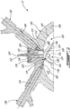
- Fig 2 illustrates a particular embodiment of such a rotary unit comprising a housing including an outer body 102 having axially-spaced end walls 104 with a peripheral wall 108 extending therebetween to form a rotor cavity 110.
- An inner surface 112 of the peripheral wall 108 of the cavity 110 has a profile defining two lobes, which is preferably an epitrochoid.
- An inner body or rotor 114 is received within the cavity 110, with the geometrical axis of the rotor 114 being offset from and parallel to the axis of the outer body 102.
- the rotor 114 has axially spaced end faces 116 adjacent to the outer body end walls 104, and a peripheral face 118 extending therebetween.
- the peripheral face 118 defines three circumferentially-spaced apex portions 120 (only one of which is shown), and a generally triangular profile with outwardly arched sides.
- the apex portions 120 are in sealing engagement with the inner surface 112 of peripheral wall 108 to form three rotating main combustion chambers 122 (only two of which are partially shown) between the inner rotor 114 and outer body 102.
- a recess 124 is defined in the peripheral face 118 of the rotor 114 between each pair of adjacent apex portions 120, to form part of the corresponding chamber 122.
- Each rotor apex portion 120 has an apex seal 126 extending from one end face 116 to the other and protruding radially from the peripheral face 118. Each apex seal 126 is biased radially outwardly against the peripheral wall 108 through a respective spring. An end seal 128 engages each end of each apex seal 126, and is biased against the respective end wall 104 through a suitable spring.
- Each end face 116 of the rotor 114 has at least one arc-shaped face seal 130 running from each apex portion 120 to each adjacent apex portion 120, adjacent to but inwardly of the rotor periphery throughout its length.
- a spring urges each face seal 130 axially outwardly so that the face seal 130 projects axially away from the adjacent rotor end face 116 into sealing engagement with the adjacent end wall 104 of the cavity 110.
- Each face seal 130 is in sealing engagement with the end seal 128 adjacent each end thereof.
- the rotor 114 is journaled on an eccentric portion of a crankshaft and includes a phasing gear co-axial with the rotor axis, which is meshed with a fixed stator phasing gear secured to the outer body co-axially with the shaft.
- the shaft rotates with the rotor 114 and the meshed gears guide the rotor 114 to perform orbital revolutions within the stator cavity.
- the shaft performs three rotations for each rotation of the rotor 114 about its own axis. Oil seals are provided around the phasing gear to prevent leakage flow of lubricating oil radially outwardly thereof between the respective rotor end face 116 and outer body end wall 104.
- At least one inlet port is defined through one of the end walls 104 or the peripheral wall 108 for admitting air (atmospheric or compressed) into one of the main combustion chambers 122
- at least one exhaust port is defined through one of the end walls 104 or the peripheral wall 108 for discharge of the exhaust gases from the main combustion chambers 122.
- the inlet and exhaust ports are positioned relative to each other and relative to the ignition member and fuel injectors (further described below) such that during one rotation of the rotor 114, each chamber 122 moves around the stator cavity with a variable volume to undergo the four phases of intake, compression, expansion and exhaust, these phases being similar to the strokes in a reciprocating-type internal combustion engine having the four-stroke cycle.
- the main chamber 122 has a variable volume Vvar varying between a minimum volume Vmin and a maximum volume Vmax.
- these ports are arranged such that the rotary engine 10 operates under the principle of the Miller or Atkinson cycle, with its volumetric compression ratio lower than its volumetric expansion ratio.
- the ports are arranged such that the volumetric compression and expansion ratios are equal or similar to one another.
- An insert 132 is received in a corresponding hole 134 defined through the peripheral wall 108 of the outer body 102, for pilot fuel injection and ignition.
- the insert 132 has a pilot subchamber 142 defined therein in communication with the rotating main combustion chambers 122.
- the pilot subchamber 142 communicates with each combustion chamber 122, in turn, when in the combustion or compression phase.
- the subchamber 142 has a circular cross-section; alternate shapes are also possible.
- the subchamber 142 communicates with the main combustion chambers 122 in a sequential manner through at least one opening 144 defined in an inner surface 146 of the insert 132.
- the subchamber 142 has a shape forming a reduced cross-section adjacent the opening 144, such that the opening 144 defines a restriction to the flow between the subchamber 142 and the cavity 110.
- the opening 144 may have various shapes and/or be defined by a pattern of multiple holes.
- the subchamber 142 is defined in the outer body 102. For example, in an embodiment where the rotary engine 100 does not include the insert 132.
- the volume of the subchamber 142 is at least 0.5% and up to 3.5% of the displacement volume, with the displacement volume being defined as the difference between the maximum and minimum volumes of one chamber 122. In another particular embodiment, the volume of the subchamber 142 corresponds to from about 0.625% to about 1.25% of the displacement volume.
- the volume of the subchamber 142 is defined as a portion of the minimum combustion volume, which is the sum of the minimum chamber volume Vmin (including the recess 124) and the volume of the subchamber V2 itself.
- the subchamber 142 has a volume of at most 10% of the minimum combustion volume, i.e. V2 ⁇ 10% of (V2 + Vmin).
- the peripheral wall 108 has a pilot injector elongated hole 148 defined therethrough, at an angle with respect to the insert 132 and in communication with the subchamber 142.
- a pilot fuel injector 150 is received and retained within the corresponding hole 148, with the tip 153 of the pilot injector 150 being received in the subchamber 142.
- the insert 132 has an ignition element elongated hole 152 defined therein extending along the direction of a transverse axis T of the outer body 102, also in communication with the subchamber 142.
- An ignition element 156 is received and retained within the corresponding hole 152, with the tip 158 of the ignition element 156 being received in the subchamber 142.
- the ignition element 156 is a glow plug. Alternate types of ignition elements 156 which may be used include, but are not limited to, plasma ignition, laser ignition, spark plug, microwave, etc.
- subchamber 142 pilot injector elongated hole 148 and ignition element elongated hole are shown and described as being provided in the insert 132, it is understood that alternately, one, any combination of or all of these elements may be defined directly in the outer body 102, for example directly in the peripheral wall 108.
- the peripheral wall 108 also has a main injector elongated hole 136 defined therethrough, in communication with the rotor cavity 110 and spaced apart from the insert 132.
- a main fuel injector 138 is received and retained within this corresponding hole 136, with the tip 140 of the main injector 138 communicating with the cavity 110 at a point spaced apart from the insert 132.
- the main injector 138 is located rearwardly of the insert 132 with respect to the direction R of the rotor rotation and revolution, and is angled to direct fuel forwardly into each of the rotating main combustion chambers 122 sequentially with a tip hole pattern designed for an adequate spray.
- the pilot injector 150 and main injector 138 inject heavy fuel, e.g. kerosene (jet fuel), equivalent biofuel, etc. into the pilot subchamber 142 and into the corresponding main chambers 122, respectively.
- the injected fuel within the pilot subchamber 142 is ignited therein, thus, creating a hot wall around the pilot subchamber 142 and the inner surface 146 of the insert body 132.
- a flow of the ignited fuel is partially restricted and directed from the pilot subchamber 142 to the main chamber 122 communicating with it, through the opening 144.
- the flow of the ignited fuel from the pilot subchamber 142 ignites the fuel injected in the main chamber 122 by the main injector 138.
- such a fuel injection system allows the combustion of heavy fuel in a rotary engine using a pilot and main injector for a staged combustion system that can burn at higher speed than typical engines burning heavy fuels.
- the system relies on the pilot subchamber 142 to initiate the combustion with an engine control system programmed in such a way to ensure adequate conditions are achieved for ignition during every combustion event.
- Such a system results in starts that are longer than a typical internal combustion engine using gasoline as the engine makes use of glow plugs or the like in order to heat the subchamber 142 before the engine starter 20 can be deactivated.
- the starter 20 needs to be oversized to drive all the components that are mechanically engaged with the internal combustion engine 12.
- the de-coupling mechanism 16 allows to separate (i.e. mechanically disengaged) the internal combustion engine 12 from the turbomachinery 14 as well as the load 18 (e.g. a helicopter gearbox which drives the helicopter main and tail rotors). Accordingly, the decoupling mechanism 16 can be used to allow the internal combustion engine 12 to be started on its own before being mechanically engaged with the turbomachinery 14 and the load 18. It will be appreciated that by starting the internal combustion engine 12 separately from the other components (e.g. the turbomachinery and the load), the engine starter can be downsized and then once going to ground idle, with all components engaged via mechanism 16, the engine 12 can provide torque to accelerate the whole system at a lower engine speed.
- the load 18 e.g. a helicopter gearbox which drives the helicopter main and tail rotors
- the de-coupling mechanism allows starting the combustion engine 12 with the engine only driving selected key accessories, such as a coolant pump 22, a fuel pump 24, an oil pump 26, a generator 28, or any other accessories susceptible to being used by an operator while an aircraft is in a hotel mode (i.e. a mode where the aircraft is on the ground with passengers loading so heating, a/c or electric power is needed).
- key accessories such as a coolant pump 22, a fuel pump 24, an oil pump 26, a generator 28, or any other accessories susceptible to being used by an operator while an aircraft is in a hotel mode (i.e. a mode where the aircraft is on the ground with passengers loading so heating, a/c or electric power is needed).
- the remaining accessories 30, 32 could be drivingly connected to the turbomachinery 14.
- the de-coupling mechanism 16 can take various forms. For instance, it can be provided in the form of a mechanical device configured to selectively mechanically disengage the output shaft of the internal combustion engine 12 from the turbomachinery 14 and the load 18.
- a non-slip clutch also known as a dog clutch could be integrated to a compounding gearbox (not shown) interconnecting the internal combustion engine 12 and the turbine section of the turbomachinery 14 to the load 18.
- the clutch could be provided between the output shaft of the engine 12 and an associated input shaft of the gearbox in such a way that the output shaft of the engine is still operable to drive selected accessories like oil pump and coolant pump.
- the clutch could be operated to selectively disconnect the output shaft of the internal combustion engine 12 from the gearbox from the turbomachinery 14 and the load 18.
- a solenoid actuator or a system with hydraulic pressure as a working fluid can be used as part of a de-coupling mechanism (a shaft that moves and engages or disengages splines or gear) in order to separate the mechanical engagement.
- a de-coupling mechanism a shaft that moves and engages or disengages splines or gear
- There type of systems would work for engagement when there is a speed match between two shafts to be engaged or at zero speed.
- the internal combustion engine 12 can be mechanically disengaged from the turbomachinery 14 and the load 18 via de-coupling mechanism 16. Thereafter, the starter 20 can be activated to start the engine 12. As described above, the combustion process is initiated in the pilot subchamber 142 and completed in the main combustion chambers 122 with the flow of the ignited fuel from the pilot subchamber 142 igniting the fuel injected in the main chambers 122. In a particular embodiment, the engine 12 is allowed to warm up and once the subchamber 142 reaches its operating temperature (the combustion system and the oil are also warm) the engine 12 is shut down. When the engine speed reaches zero, the engine 12 is mechanically re-engaged with the turbomachinery 14 and the load 18.
- the engine starter 20 is then activated for a second time to re-start the engine 12. But now because the combustion system is warm and the subchamber 142 is warm, the ignition will happen at a much lower speed, thereby providing the ability to use the engine 12 to overcome the inertia of all the other components (the turbomachinery 14 and the load 18) that are now engaged with the engine 12. With the warm engine 12, it is now possible to accelerate faster and to downsize the starter for the system.
- turbomachinery With systems where the turbomachinery is connected to the output shaft and the turbine of the turbomachinery is able to accelerate with the air flow from the running engine to achieve a speed match with the engine, then the system can be engaged without a friction clutch and without shutting down (dog clutch type system) the combustion engine.
- the turbomachinery may have to be sized for speeds close to idle or, alternatively, the idle speed of the engine may have to be raised considerably.
- Fig. 3 illustrates another embodiment in which like elements are identified with like reference numerals.
- the embodiment of Fig. 3 essentially differs from the embodiment of Fig. 1 in that the de-coupling mechanism 16 is provided between the combustion engine 12 and the load to be driven 18 (e.g. the helicopter gearbox).
- the turbomachinery 14 remains mechanically engaged with the combustion engine 12 at all time. It is only the load 18 that is mechanically disengaged from the combustion engine 12 at start.
- a second starter or hydraulic system would be needed to accelerate the output shaft to a speed match if it is desired to obtain a speed match between the output shaft of the system and the combustion engine output shaft to avoid having to shut down the engine after the warming up phase.
- turbomachinery 14 could be disengaged from the engine 12 when initially started.
- accessories can be distributed as seen fit for operability or packaging purposes.
- a method for starting a turbocompounded aircraft engine system having a turbomachinery and an internal combustion engine with a pilot subchamber to initiate combustion of heavy fuel, the turbomachinery compounding with the internal combustion engine to drive a load comprises: mechanically decoupling the internal combustion engine from the turbomachinery and/or the load for starting.
- the internal combustion engine is started on its own and is allowed to warm up without turning the turbomachinery and/or the load (e.g. aircraft main transmission, main rotor and tail rotor).
- the internal combustion engine is, however, connected via the gearbox (or direct on crankshaft) to accessories (e.g.
- the internal combustion engine is shut down and immediately when the engine speed reaches zero, it is mechanically engaged to the turbomachinery as well as the aircraft transmission and rotors.
- the engine starter is then activated for a second time, but this time the turbomachinery and aircraft transmission/rotors are accelerated with the help of the internal combustion engine.
- the engine is warm and, thus, produces torque at a much lower speed, and therefore it aids in the start of the engaged system, allowing the engine to reach ground idle condition in a shorter amount of time.
- a method of starting a turbocompounded engine system comprising an internal combustion engine and a turbomachinery for driving a load.
- the method comprising: mechanically disengaging the internal combustion engine from at least one of the load and the turbomachinery, starting the internal combustion engine; allowing the internal combustion engine to warm up; and then mechanically re-engaging the internal combustion engine with the at least one of the load and the turbomachinery.
- starting the engine separately from the other components e.g. turbomachinery
- the de-coupling mechanism allows to minimize the compounding gearbox complexity, starter size as well as fuel consumption in certain conditions. It provides for a better operability of the turbocompounded engine system.
Landscapes
- Engineering & Computer Science (AREA)
- Chemical & Material Sciences (AREA)
- Combustion & Propulsion (AREA)
- Mechanical Engineering (AREA)
- General Engineering & Computer Science (AREA)
- Physics & Mathematics (AREA)
- Geometry (AREA)
- Output Control And Ontrol Of Special Type Engine (AREA)
- Supercharger (AREA)
Applications Claiming Priority (1)
| Application Number | Priority Date | Filing Date | Title |
|---|---|---|---|
| US16/184,299 US20200149467A1 (en) | 2018-11-08 | 2018-11-08 | Method and system for starting a turbocompounded engine |
Publications (2)
| Publication Number | Publication Date |
|---|---|
| EP3650672A2 true EP3650672A2 (fr) | 2020-05-13 |
| EP3650672A3 EP3650672A3 (fr) | 2020-05-20 |
Family
ID=68470441
Family Applications (1)
| Application Number | Title | Priority Date | Filing Date |
|---|---|---|---|
| EP19207538.0A Withdrawn EP3650672A3 (fr) | 2018-11-08 | 2019-11-06 | Procédé et système de démarrage de turbomélangeur |
Country Status (4)
| Country | Link |
|---|---|
| US (1) | US20200149467A1 (fr) |
| EP (1) | EP3650672A3 (fr) |
| CN (1) | CN111156088A (fr) |
| CA (1) | CA3058138A1 (fr) |
Citations (4)
| Publication number | Priority date | Publication date | Assignee | Title |
|---|---|---|---|---|
| US7753036B2 (en) | 2007-07-02 | 2010-07-13 | United Technologies Corporation | Compound cycle rotary engine |
| US7775044B2 (en) | 2003-02-24 | 2010-08-17 | Pratt & Whitney Canada Corp. | Low volumetric compression ratio integrated turbo-compound rotary engine |
| US20150275749A1 (en) | 2012-07-20 | 2015-10-01 | Pratt & Whitney Canada Corp. | Compound cycle engine |
| US20150275756A1 (en) | 2012-07-20 | 2015-10-01 | Pratt & Whitney Canada | Compound cycle engine |
Family Cites Families (12)
| Publication number | Priority date | Publication date | Assignee | Title |
|---|---|---|---|---|
| US4096828A (en) * | 1972-01-24 | 1978-06-27 | Toyo Kogyo Co. Ltd. | Rotary piston internal combustion engine |
| FR2701062B1 (fr) * | 1993-01-29 | 1995-04-07 | Siemens Automotive Sa | Procédé et dispositif de réduction des émissions de gaz nocifs produites par un moteur à combustion interne propulsant un véhicule automobile. |
| US6125813A (en) * | 1997-06-09 | 2000-10-03 | Patrick Power Products, Inc. | Prechamber combustion for a rotary diesel engine |
| DE102010047518A1 (de) * | 2010-10-05 | 2011-07-07 | Daimler AG, 70327 | Vorrichtung zur Energierückgewinnung aus einem Abgasstrom einer Verbrennungskraftmaschine |
| WO2012097349A2 (fr) * | 2011-01-13 | 2012-07-19 | Cummins Inc. | Système, procédé et appareil pour commander la distribution de puissance de sortie dans un groupe motopropulseur hybride |
| ITFI20120194A1 (it) * | 2012-10-01 | 2014-04-02 | Nuovo Pignone Srl | "a turbine-driven reciprocating compressor and method" |
| US9200563B2 (en) * | 2013-03-12 | 2015-12-01 | Pratt & Whitney Canada Corp. | Internal combustion engine with common rail pilot and main injection |
| GB2533157B (en) * | 2014-12-12 | 2019-06-12 | Perkins Engines Co Ltd | Thermal energy management system and method |
| CN104612815B (zh) * | 2015-01-19 | 2017-12-15 | 同济大学 | 一种车用涡轮增压系统 |
| US10590842B2 (en) * | 2015-06-25 | 2020-03-17 | Pratt & Whitney Canada Corp. | Compound engine assembly with bleed air |
| US10240521B2 (en) * | 2015-08-07 | 2019-03-26 | Pratt & Whitney Canada Corp. | Auxiliary power unit with variable speed ratio |
| JP6420377B2 (ja) * | 2017-01-13 | 2018-11-07 | 本田技研工業株式会社 | 制御装置 |
-
2018
- 2018-11-08 US US16/184,299 patent/US20200149467A1/en not_active Abandoned
-
2019
- 2019-10-08 CA CA3058138A patent/CA3058138A1/fr not_active Abandoned
- 2019-11-06 EP EP19207538.0A patent/EP3650672A3/fr not_active Withdrawn
- 2019-11-08 CN CN201911088190.6A patent/CN111156088A/zh active Pending
Patent Citations (4)
| Publication number | Priority date | Publication date | Assignee | Title |
|---|---|---|---|---|
| US7775044B2 (en) | 2003-02-24 | 2010-08-17 | Pratt & Whitney Canada Corp. | Low volumetric compression ratio integrated turbo-compound rotary engine |
| US7753036B2 (en) | 2007-07-02 | 2010-07-13 | United Technologies Corporation | Compound cycle rotary engine |
| US20150275749A1 (en) | 2012-07-20 | 2015-10-01 | Pratt & Whitney Canada Corp. | Compound cycle engine |
| US20150275756A1 (en) | 2012-07-20 | 2015-10-01 | Pratt & Whitney Canada | Compound cycle engine |
Also Published As
| Publication number | Publication date |
|---|---|
| US20200149467A1 (en) | 2020-05-14 |
| CN111156088A (zh) | 2020-05-15 |
| CA3058138A1 (fr) | 2020-05-08 |
| EP3650672A3 (fr) | 2020-05-20 |
Similar Documents
| Publication | Publication Date | Title |
|---|---|---|
| EP3470649B1 (fr) | Moteur rotatif et procédé de combustion de combustible | |
| US10267217B2 (en) | Internal combustion engine with common rail injection | |
| EP2551448B1 (fr) | Moteur rotatif à combustion interne avec une sous-chambre pilote et procédé d'injection de carburant | |
| CA2844183C (fr) | Moteur a combustion interne a injection pilote et principale | |
| EP3299607B1 (fr) | Procédé de fonctionnement d'un moteur ayant une sous-chambre pilote dans des conditions de charge partielle | |
| US10557407B2 (en) | Rotary internal combustion engine with pilot subchamber | |
| US10801394B2 (en) | Rotary engine with pilot subchambers | |
| US11306651B2 (en) | Method of operating an internal combustion engine | |
| EP3650672A2 (fr) | Procédé et système de démarrage de turbomélangeur | |
| WO2000012867A1 (fr) | Moteur a combustion interne |
Legal Events
| Date | Code | Title | Description |
|---|---|---|---|
| PUAI | Public reference made under article 153(3) epc to a published international application that has entered the european phase |
Free format text: ORIGINAL CODE: 0009012 |
|
| STAA | Information on the status of an ep patent application or granted ep patent |
Free format text: STATUS: THE APPLICATION HAS BEEN PUBLISHED |
|
| PUAL | Search report despatched |
Free format text: ORIGINAL CODE: 0009013 |
|
| AK | Designated contracting states |
Kind code of ref document: A2 Designated state(s): AL AT BE BG CH CY CZ DE DK EE ES FI FR GB GR HR HU IE IS IT LI LT LU LV MC MK MT NL NO PL PT RO RS SE SI SK SM TR |
|
| AX | Request for extension of the european patent |
Extension state: BA ME |
|
| AK | Designated contracting states |
Kind code of ref document: A3 Designated state(s): AL AT BE BG CH CY CZ DE DK EE ES FI FR GB GR HR HU IE IS IT LI LT LU LV MC MK MT NL NO PL PT RO RS SE SI SK SM TR |
|
| AX | Request for extension of the european patent |
Extension state: BA ME |
|
| RIC1 | Information provided on ipc code assigned before grant |
Ipc: F02B 53/14 20060101ALI20200415BHEP Ipc: F02N 19/00 20100101ALI20200415BHEP Ipc: F02B 41/10 20060101AFI20200415BHEP Ipc: F01C 11/00 20060101ALI20200415BHEP Ipc: F02C 6/12 20060101ALI20200415BHEP Ipc: F02B 39/04 20060101ALI20200415BHEP |
|
| 18D | Application deemed to be withdrawn |
Effective date: 20201121 |