EP3650307A1 - Determination of a speed profile of a railway vehicle for driving on a given route - Google Patents
Determination of a speed profile of a railway vehicle for driving on a given route Download PDFInfo
- Publication number
- EP3650307A1 EP3650307A1 EP18204648.2A EP18204648A EP3650307A1 EP 3650307 A1 EP3650307 A1 EP 3650307A1 EP 18204648 A EP18204648 A EP 18204648A EP 3650307 A1 EP3650307 A1 EP 3650307A1
- Authority
- EP
- European Patent Office
- Prior art keywords
- route
- driving
- phase
- railway vehicle
- speed profile
- Prior art date
- Legal status (The legal status is an assumption and is not a legal conclusion. Google has not performed a legal analysis and makes no representation as to the accuracy of the status listed.)
- Withdrawn
Links
Images

Classifications
-
- B—PERFORMING OPERATIONS; TRANSPORTING
- B61—RAILWAYS
- B61L—GUIDING RAILWAY TRAFFIC; ENSURING THE SAFETY OF RAILWAY TRAFFIC
- B61L15/00—Indicators provided on the vehicle or train for signalling purposes
- B61L15/0062—On-board target speed calculation or supervision
-
- B—PERFORMING OPERATIONS; TRANSPORTING
- B61—RAILWAYS
- B61L—GUIDING RAILWAY TRAFFIC; ENSURING THE SAFETY OF RAILWAY TRAFFIC
- B61L27/00—Central railway traffic control systems; Trackside control; Communication systems specially adapted therefor
- B61L27/20—Trackside control of safe travel of vehicle or train, e.g. braking curve calculation
Definitions
- the invention relates to a method for determining a speed profile of a railway vehicle for driving on a given route, wherein the railway vehicle consumes energy at least in speeding up phases and cruising phases.
- a speed profile of a railway vehicle for driving on a given route is generally adjusted to a given timetable of the railway vehicle. Hence, travel times needed for driving from one stopping point to the next stopping point of the railway vehicle are fixed.
- One objective of the invention is to provide a method for determining a speed profile of a railway vehicle for driving on a given route.
- the route is subdivided into track sections.
- Sectional energy consumptions for the respective track sections include respectively the energy consumed at least within the speeding up phase(s) and cruising phase(s) of the respective track section.
- the sectional energy consumptions for the respective track sections may be calculated, particularly indirectly or directly.
- the total energy consumption adding together the sectional energy consumptions of the track sections is reduced, wherein an optimised speed profile for driving on the route is determined.
- the total energy consumption may be a theoretical total energy consumption for driving on the route.
- the total energy consumption is reduced, particularly instead of reducing the sectional energy consumptions of the railway vehicle individually.
- the invention is based on the finding that a speed profile of a railway vehicle for a given route can be optimised by reducing the total energy consumption for this route.
- the total energy consumption in turn preferably depends on the speed profile.
- some mathematical effort may be necessary to exhibit the method.
- an optimal driving strategy of the railway vehicle can be determined.
- the total energy consumption of the railway vehicle can be reduced, particularly by using the optimised speed profile.
- the total energy consumption of the railway vehicle can be reduced, particularly without adapting the hardware of the railway vehicle itself.
- each track section comprises at least one speeding up phase. Further, it is preferred that each track section comprises at least one cruising phase.
- each sectional energy consumption for the respective track section includes respectively the energy consumed at least within all speeding up phase(s) - if existing - and all cruising phase(s) - if existing - of the respective track section.
- an acceleration of the railway vehicle is positive and/or a velocity of the railway vehicle is increasing. Accordingly, during the speeding up phase, the energy consumption of the railway vehicle may be positive.
- the acceleration of the railway vehicle is zero and/or the velocity of the railway vehicle is constant.
- the energy consumption of the railway vehicle may be positive, because resistance forces may act on the railway vehicle.
- the optimised speed profile for driving on the route may comprise at least one coasting phase. Preferably, no energy is consumed or regained in the coasting phase.
- the energy consumption of the railway vehicle is zero. Accordingly, during the coasting phase, acceleration of the railway vehicle may be decreased relative to the acceleration in the phase before, because resistance forces may act on the railway vehicle. If the acceleration is negative, than the railway vehicle decelerates.
- the optimised speed profile for driving on the route may comprise sectional speed profiles, preferentially each for driving on the respective track section.
- each sectional speed profile for driving on the respective track section comprises at least one coasting phase.
- At least one sectional speed profile may comprise at least two coasting phases.
- the total energy consumption for the route includes the energy regained within at least one braking phase.
- the optimised speed profile for driving on the route may comprise the at least one braking phase.
- the railway vehicle may regain energy in the at least one braking phase.
- the acceleration of the railway vehicle is negative - also called deceleration - and/or the speed of the railway vehicle is decreasing.
- some energy may be regained. Accordingly, during the braking phase, the energy consumption of the railway vehicle may be negative.
- each sectional speed profile for driving on the respective track section comprises at least one braking phase.
- the sectional energy consumption for a respective track section may include the energy regained within the braking phase(s) of the respective track section.
- a total travel time available for the route is predefined.
- section travel times needed for driving the respective track sections are determined.
- the section travel times may be determined by means of the optimised speed profile.
- Each determined section travel time may lie within a respective specifiable time interval.
- Each time interval may be predefined and/or calculable.
- a timetable of the railway vehicle for driving on the given route can be determined.
- the timetable of the railway vehicle for driving on the given route can be determined by means of the optimised speed profile.
- the optimised speed profile for driving on the route may comprise sectional speed profiles.
- Each sectional speed profile may be a sectional speed profile for driving on the respective track section.
- each sectional speed profile comprises at least some moving phases of the following types: speeding up phase, cruising phase, coasting phase and braking phase.
- the types of moving phases may be the types of moving phases named above.
- Each sectional speed profile may comprise all named types of moving phases.
- phase duration times of the moving phases are determined, particularly by means of the optimised speed profile.
- a phase duration time may specify the duration of the respective moving phase.
- optimal switching points between different moving phases may be determined.
- optimal duration of the respective moving phases may be determined.
- At least one acceleration applied in at least one speeding up phase of at least one sectional speed profile may be determined. Particularly, the accelerations applied in the speeding up phases of the sectional speed profiles may be determined.
- At least one deceleration applied in at least one braking phase of at least one sectional speed profile may be determined. Particularly, the decelerations applied in the braking phases of the sectional speed profiles may be determined.
- At least one velocity applied in at least one cruising phase may be determined.
- the velocities applied in the cruising phases of the sectional speed profiles may be determined.
- each sectional speed profile of the railway vehicle may comprise at least three of the types of moving phases.
- each sectional speed profile of the railway vehicle may comprise all types of moving phases, particularly speeding up phase, cruising phase, coasting phase and braking phase.
- each speed profile comprises at least three, particularly at least four, moving phases.
- a speed profile may comprise more than four moving phases, particularly by repeating one or more type(s) of the moving phases.
- a maximum allowed acceleration of the railway vehicle is considered for the determination of the optimised speed profile for driving on the route.
- a maximum allowed velocity of the railway vehicle is considered for the determination of the optimised speed profile for driving on the route.
- a maximum allowed deceleration of the railway vehicle is considered for the determination of the optimised speed profile for driving on the route.
- a maximum allowed parameter may be allowed as maximum for reasons of safety, of passenger comfort and/or of physical limits and/or for other reasons.
- the maximum allowed velocity may depend on the track section or on the part of the track section.
- a minimum allowed acceleration and/or a minimum allowed deceleration of the railway vehicle may depend on the track section or on the part of the track section.
- railway vehicle parameters are considered for the determination of the optimised speed profile for driving on the route.
- Some railway parameters may be: the mass of the railway vehicle, the efficiency in traction, the efficiency in braking, the maximum tractive force and/or other parameters.
- route parameters may be considered for the determination of the optimised speed profile for driving on the route.
- Some route parameters may be: route profile, ascending slope, descending slope, radius of curvature and/or other parameters. Particularly, for the route parameters, the direction of travel may be considered.
- the route parameters may depend on the track section or on the part of the track section.
- each track section is a section of a given route between two stopping points on the given route.
- the track section is a section of a given route between two neighbouring stopping points on the given route.
- the track section may be any section of a given route.
- a stopping point of a railway vehicle may be a railway station, a signal station and/or similar.
- the reduction of the total energy consumption and the determination of the optimised speed profile for driving on the route are executed by means of a multidimensional optimisation model.
- the invention relates to a usage of the method described above for determining a system operational mode of a railway vehicle pool comprising several railway vehicles for driving on several given routes.
- the invention relates to the method described above, which may be used for determining a system operational mode of a railway vehicle pool comprising several railway vehicles for driving on several given routes.
- a system energy consumption adding together the total energy consumptions of the railway vehicles for driving on the respective routes is reduced, wherein particularly the system operational mode of the railway vehicle pool is determined.
- system energy consumption may be a theoretical system energy consumption of several railway vehicles for driving on several given routes.
- the system energy consumption may be reduced instead of reducing the total energy consumptions of the railway vehicles individually.
- the speed profiles of the railway vehicles for driving on the respective routes may be further adjusted.
- a relative timing of the several railway vehicles for driving on the respective routes may be determined, particularly by means of the optimal driving strategy.
- a timetable of the several railway vehicles for driving on the respective routes can be determined.
- the system energy consumption may be reduced, particularly may be minimised.
- the determination of the optimal driving strategy may take further constraints and/or circumstances into account.
- only one railway vehicle may be allowed within each track section.
- the optimal driving strategy may take into account that the power supply system delivering the energy electrically has a limited capacity and/or limited electrical power, which can be delivered. Hence, simultaneously acceleration of all railway vehicles may be forbidden. Also, simultaneously deceleration of all railway vehicles may be forbidden.
- the optimal driving strategy may take into account that regained energy of a braking railway vehicle can be used for another, accelerating railway vehicle.
- the invention relates to a computer program with code, which, when executed on a computer, realises any of the methods described above.
- the invention relates to a computer readable medium having a computer program for execution on a computer, which computer program, when executed on a computer, causes the computer to perform any of the methods described above.
- FIG 1 schematically shows a flow chart 2.
- the flow chart 2 schematically gives an overview over the method for determining a speed profile of a railway vehicle for driving on a given route 6.
- the method may be realised in software, particularly by means of a computer program.
- the computer program may comprise code, which, when executed on a computer, realises the method.
- the computer program may be saved on a computer readable medium.
- the method is executed by means of a multidimensional optimisation model 4.
- the route 6 is predefined.
- the railway vehicle when driving on the route 6, consumes energy at least in speeding up phases 20 and cruising phases 22 (see FIG 2 ).
- the route 6 is subdivided into track sections 8. Also the track sections 8 are predefined. For instance, each track section 8 is a section of the route 6 between two stopping points 10 on the route 6, particularly between two neighbouring stopping points 10 on the route 6.
- a stopping point 10 on the route 6 may be a railway station or a signal station, at which the railway vehicle stops when driving on the route 6.
- a total travel time t route available for the route 6 is predefined.
- a maximum allowed acceleration of the railway vehicle a maximum allowed deceleration of the railway vehicle, a maximum allowed velocity of the railway vehicle and route parameters are predefined. Some or all of these parameters may depend on the track section or on part of the track section.
- the route parameters may depend on profiles of the track sections 8.
- the route parameters may comprise the profiles of the track sections 8 and/or average values determined from the profiles.
- railway vehicle parameters are predefined.
- each sectional energy consumption 12 includes respectively the energy consumed at least within the speeding up phase(s) 20 and cruising phase(s) 22 of the respective track section 8 (see FIG 2 ).
- the sectional energy consumptions 12 depend on the speed profile 16 for driving on the route 6, particularly on the sectional speed profile 18 for driving on the respective track section 8.
- the total energy consumption 14 adding together the sectional energy consumptions 12 of the track sections 8 is reduced, wherein an optimised speed profile 16 for driving on the route 6 is determined.
- the multidimensional optimisation model 4 comprises a constrained gradient optimisation algorithm (not shown).
- An initial speed profile 16 for driving on the route 6 may be given.
- the initial speed profile 16 is subdivided into initial sectional speed profiles 18 for driving on the track sections 8 of the route 6.
- Sectional energy consumptions 12 for driving on the respective track sections 8 using the initial sectional speed profiles 18 are calculated.
- the calculated sectional energy consumptions 12 include respectively the energy consumed at least within the speeding up phase(s) and cruising phase(s) of the respective track section 8.
- a total energy consumption 14 for driving on the route 6 adds together the sectional energy consumptions 12 of the track sections 8.
- a function for calculating the total energy consumption 14 is formulated.
- the gradient of the function calculating the total energy consumption 14 is determined. Also, the value of the total energy consumption 14 may be determined, if necessary. In the direction indicated by the gradient, a next speed profile is chosen for the next step of iteration and so on.
- the total energy consumption 14 is reduced, particularly minimised, wherein an optimised speed profile 16 for driving on the route is determined.
- Section travel times t sec needed for driving the respective track sections 8 are determined, particularly by means of the optimised speed profile 16.
- the route 6 is subdivided exemplarily into four track sections 8.
- four section travel times t sec1 , t sec2 , t sec3 , t sec4 are determined.
- another number of track sections 8 as well as another number of section travel times t sec is possible.
- One or several initial speed profiles 16 may be given. The latter is preferred to find several local optima, if present.
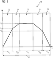
- FIG 2 shows a diagram comprising exemplarily a sectional speed profile 18 for driving on one of the track sections 8 of the route 6.
- the sectional speed profile 18 can be determined by means of the method described in FIG 1 .
- the sectional speed profile 18 shows the velocity v of the railway vehicle over time t.
- the shown sectional speed profile 18 comprises the moving phases of the following types of speeding up phase 20, cruising phase 22, coasting phase 24 and braking phase 26.
- the sectional speed profile 18 comprises five moving phases.
- the five moving phases have the following order: the first phase is the speeding up phase 20, the second phase is the first coasting phase 24, the third phase is the cruising phase 22, the forth phase is the second coasting phase 24 and the fifth phase is the braking phase 26.
- the railway vehicle accelerates.
- the acceleration to apply in the speeding up phase 20 is determined.
- the phase duration time t a of the speeding up phase 20 is determined.
- the track section 8 starts at a stopping point 10 of the railway vehicle. Hence, at the beginning of the speeding up phase 20, the velocity v is zero. At the end of the speeding up phase 20, the velocity v reaches the value v 1 .
- the velocity v 1 can be determined as a target velocity for the end of the speeding up phase 20.
- the first coasting phase 24 follows as the second phase. Within the first coasting phase 24, no energy is consumed or regained. Hence, the energy consumption of the railway vehicle is zero within the first coasting phase 24. Accordingly, during the first coasting phase 24, the acceleration of the railway vehicle is decreased relative to the acceleration in the phase before (here relative to the acceleration in the speeding up phase 20), because resistance forces act on the railway vehicle.
- the acceleration of the railway vehicle may be constant during the first coasting phase 24 (as shown).
- the acceleration of the railway vehicle may be decreasing during the first coasting phase 24.
- the phase duration time t c1 of the first coasting phase 24 is determined.
- the velocity v 2 can be determined as a target velocity for the end of the first coasting phase 24 - and preferentially as a target velocity for the following cruising phase 22. It is preferred, that v 2 > v 1 .
- the cruising phase 22 follows as the third phase P3.
- the acceleration of the railway vehicle is zero.
- the velocity v of the railway vehicle is constant at the value v 2 .
- the phase duration time t v of the cruising phase 22 is determined.
- the energy consumption of the railway vehicle is positive, because resistance forces act on the railway vehicle.
- the second coasting phase 24 follows as the forth phase.
- the energy consumption of the railway vehicle is zero within the second coasting phase 24.
- the railway vehicle decelerates during the second coasting phase 24, because resistance forces act on the railway vehicle.
- the acceleration of the railway vehicle is decreased relative to the acceleration in the phase before (here relative to the acceleration in the cruising phase 22, particularly relative to zero acceleration).
- the phase duration time t c2 of the second coasting phase 24 is determined.
- the velocity v reaches the value v 3 .
- the velocity v 3 can be determined as a target velocity for the end of the second coasting phase 24. It is preferred, that v 2 > v 3 .
- the braking phase 26 follows as the fifth phase.
- the acceleration of the railway vehicle is negative, also called deceleration.
- the deceleration to apply in the braking phase 26 is determined.
- the phase duration time t b of the second braking phase 26 is determined.
- the velocity of the railway vehicle is decreasing during the braking phase 26 until zero. Hence, zero can be the target velocity for the end of the braking phase 26.
- the section travel time t sec of the regarding track section 8 can be calculated by adding together the phase duration times t a , t v , t c , t b of the moving phases 20, 22, 24, 26.
- t sec t a + t c1 + t v + t c2 + t b
- the energy consumption of the railway vehicle may be negative.
- the regained energy is considered in the sectional energy consumption 12 of the railway vehicle for driving on the track section 8.
- the regained energy is considered in the total energy consumption 14 of the railway vehicle for driving on the route 6.
- the number of moving phases 20, 22, 24, 26 as well as the order of moving phases 20, 22, 24, 26 is optimised for each track section 8, so that the total energy consumption is reduced.
- the phase duration times t a , t v , t c , t b of the moving phases 20, 22, 24, 26 are optimised, so that the total energy consumption 14 is reduced.
- the section travel times t sec are optimised, so that the total energy consumption 14 is reduced.
- the speed profile 16 for the route 6 should comprise at least one coasting phase 24. However, it is preferred that each sectional speed profile comprises at least one coasting phase 24.
- the coasting phase(s) 24 may start as early as possible to save energy within the coasting phase(s) 24. On the other hand, the coasting phase(s) 24 may start as late as necessary to hold the constraints of total travel time available, maximum allowed acceleration and maximum allowed velocity and/or to reduce the energy consumed within other moving phases.
- phase duration time(s) t c of the coasting phase(s) 24 may be as long as possible to save energy within the coasting phase(s) 24.
- the phase duration time(s) t c of the coasting phase(s) 24 may be as short as necessary to hold the constraints of total travel time available, maximum allowed acceleration and maximum allowed velocity and/or to reduce the energy consumed within other moving phases.
- determining the optimal phase duration time t c of the coasting phase(s) 24 may help for reducing the total energy consumption 14.
- all sectional speed profiles 18 comprise the moving phases of the following types of speeding up phase 20, cruising phase 22, coasting phase 24 and braking phase 26.
- Each sectional speed profile 18 can be more complex, for example, if a maximum allowed velocity and/or a maximum allowed acceleration changes within a track section 8 or for other reasons.
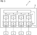
- FIG 3 schematically shows a flowchart 30.
- the flowchart 30 gives a schematic overview of the usage of the method described in FIG 1 for determining an optimal driving strategy 32 of several railway vehicles for driving on several given routes 6.
- the following description is restricted essentially to the differences from the embodiment of FIG 1 , to which is referred regarding unchanged features and functions. Essentially identical elements are generally denoted by the same reference numbers and not mentioned features are included in the following embodiment without being described again.
- Constraints have to be considered for each route 6 and for each railway vehicle. The constraints may depend on the route 6 and/or on the railway vehicle.
- the routes 6 are given/predefined. Each route 6 is subdivided into track sections 8.
- Sectional energy consumptions 12 for the respective track sections 8 can be calculated, which include respectively the energy consumed at least within the speeding up phase(s) 20 and cruising phase(s) 22 of the respective track section 8.
- the sectional energy consumptions 12 depend on the speed profile 16 for driving on the route 6, particularly on the sectional speed profile 18 for driving on the respective track section 8 (see FIG 1 ).
- a system energy consumption 34 adding together the total energy consumptions 14 of the railway vehicles for driving on the respective routes 6 is reduced, wherein the optimal driving strategy 32 of the several railway vehicles is determined.
- a respective optimised speed profile (which is determined in analogy to FIG 1 ) may be used as an initial speed profile 16 for driving on the respective route 6.
- an initial timing of the several railway vehicles for driving on the respective routes may be used.
- system energy consumption 34 may be reduced instead of reducing the total energy consumptions 14 of the railway vehicles individually.
- the speed profiles 16 of the railway vehicles for driving on the respective routes 6 may be further adjusted.
- the sectional speed profiles 18 of the respective speed profiles 16 may be further adjusted.
- the optimal driving strategy 32 may take into account that the power supply system delivering the energy electrically has a limited capacity and/or limited electrical power, which can be delivered. Hence, simultaneously acceleration of all railway vehicles may be forbidden. Also, simultaneously deceleration of all railway vehicles may be forbidden.
- the optimal driving strategy 32 may take into account that regained energy of a braking railway vehicle can be used for another, accelerating railway vehicle.
- the optimal driving strategy 32 considers that only one railway vehicle is allowed within each track section 8.
Landscapes
- Engineering & Computer Science (AREA)
- Mechanical Engineering (AREA)
- Train Traffic Observation, Control, And Security (AREA)
- Electric Propulsion And Braking For Vehicles (AREA)
Abstract
The invention relates to a method for determining a speed profile (16) of a railway vehicle for driving on a given route (6), wherein the railway vehicle consumes energy at least in speeding up phases (20) and cruising phases (22).
An enhanced method for determining a speed profile (16) of a railway vehicle for driving on a given route (6) may be achieved in that, the route (6) is subdivided into track sections (8), and sectional energy consumptions (12) for the respective track sections (8) include respectively the energy consumed at least within the speeding up phase(s) (20) and cruising phase(s) (22) of the respective track section (8). The total energy consumption (14) adding together the sectional energy consumptions (12) of the track sections (8) is reduced, wherein an optimised speed profile (16) for driving on the route (6) is determined.
Description
- The invention relates to a method for determining a speed profile of a railway vehicle for driving on a given route, wherein the railway vehicle consumes energy at least in speeding up phases and cruising phases.
- Minimising energy consumption of a railway vehicle is an important issue in railway transportation. Most existing studies focus on the improvement of hardware conditions such as mass reduction, resistance reduction, space utilization, regenerative braking and energy storage.
- However, for a trip with fixed locomotive equipment on a given route, the energy consumption is far from being fixed because it is influenced of trip time and speed profile.
- A speed profile of a railway vehicle for driving on a given route is generally adjusted to a given timetable of the railway vehicle. Hence, travel times needed for driving from one stopping point to the next stopping point of the railway vehicle are fixed.
- One objective of the invention is to provide a method for determining a speed profile of a railway vehicle for driving on a given route.
- This objective is accomplished by means of a method according to claim 1.
- In the method for determining a speed profile of a railway vehicle for driving on a given route, wherein the railway vehicle - particularly when driving on the route - consumes energy at least in speeding up phases and cruising phases, according to the invention, the route is subdivided into track sections. Sectional energy consumptions for the respective track sections include respectively the energy consumed at least within the speeding up phase(s) and cruising phase(s) of the respective track section. The sectional energy consumptions for the respective track sections may be calculated, particularly indirectly or directly.
- The total energy consumption adding together the sectional energy consumptions of the track sections is reduced, wherein an optimised speed profile for driving on the route is determined.
- By reducing the total energy consumption, it may be minimised.
- The total energy consumption may be a theoretical total energy consumption for driving on the route.
- By means of the method, the total energy consumption is reduced, particularly instead of reducing the sectional energy consumptions of the railway vehicle individually.
- The invention is based on the finding that a speed profile of a railway vehicle for a given route can be optimised by reducing the total energy consumption for this route. However, the total energy consumption in turn preferably depends on the speed profile. Hence, some mathematical effort may be necessary to exhibit the method.
- By means of the invention, an optimal driving strategy of the railway vehicle can be determined. The total energy consumption of the railway vehicle can be reduced, particularly by using the optimised speed profile. Moreover, the total energy consumption of the railway vehicle can be reduced, particularly without adapting the hardware of the railway vehicle itself.
- Preferentially, each track section comprises at least one speeding up phase. Further, it is preferred that each track section comprises at least one cruising phase.
- Advantageously, each sectional energy consumption for the respective track section includes respectively the energy consumed at least within all speeding up phase(s) - if existing - and all cruising phase(s) - if existing - of the respective track section.
- Expediently, during the speeding up phase, an acceleration of the railway vehicle is positive and/or a velocity of the railway vehicle is increasing. Accordingly, during the speeding up phase, the energy consumption of the railway vehicle may be positive.
- Expediently, during the cruising phase, the acceleration of the railway vehicle is zero and/or the velocity of the railway vehicle is constant. However, during the cruising phase, the energy consumption of the railway vehicle may be positive, because resistance forces may act on the railway vehicle.
- The optimised speed profile for driving on the route may comprise at least one coasting phase. Preferably, no energy is consumed or regained in the coasting phase.
- Expediently, during the coasting phase, the energy consumption of the railway vehicle is zero. Accordingly, during the coasting phase, acceleration of the railway vehicle may be decreased relative to the acceleration in the phase before, because resistance forces may act on the railway vehicle. If the acceleration is negative, than the railway vehicle decelerates.
- The optimised speed profile for driving on the route may comprise sectional speed profiles, preferentially each for driving on the respective track section.
- It is preferred that each sectional speed profile for driving on the respective track section comprises at least one coasting phase.
- At least one sectional speed profile, particularly each sectional speed profile, may comprise at least two coasting phases.
- Advantageously, the total energy consumption for the route includes the energy regained within at least one braking phase.
- Thus, the optimised speed profile for driving on the route may comprise the at least one braking phase. The railway vehicle may regain energy in the at least one braking phase.
- Expediently, during the braking phase, the acceleration of the railway vehicle is negative - also called deceleration - and/or the speed of the railway vehicle is decreasing. During the braking phase, some energy may be regained. Accordingly, during the braking phase, the energy consumption of the railway vehicle may be negative.
- It is preferred that each sectional speed profile for driving on the respective track section comprises at least one braking phase. The sectional energy consumption for a respective track section may include the energy regained within the braking phase(s) of the respective track section.
- It is advantageous that a total travel time available for the route is predefined.
- However, it is preferred that section travel times needed for driving the respective track sections are determined. The section travel times may be determined by means of the optimised speed profile.
- Each determined section travel time may lie within a respective specifiable time interval. Each time interval may be predefined and/or calculable.
- By determining the section travel times, a timetable of the railway vehicle for driving on the given route can be determined. Thus, the timetable of the railway vehicle for driving on the given route can be determined by means of the optimised speed profile.
- As mentioned above, the optimised speed profile for driving on the route may comprise sectional speed profiles. Each sectional speed profile may be a sectional speed profile for driving on the respective track section.
- It is preferred that each sectional speed profile comprises at least some moving phases of the following types: speeding up phase, cruising phase, coasting phase and braking phase. The types of moving phases may be the types of moving phases named above.
- Each sectional speed profile may comprise all named types of moving phases.
- It is advantageous, that phase duration times of the moving phases are determined, particularly by means of the optimised speed profile. A phase duration time may specify the duration of the respective moving phase.
- In this way, optimal switching points between different moving phases may be determined. Moreover, in this way, optimal duration of the respective moving phases may be determined.
- At least one acceleration applied in at least one speeding up phase of at least one sectional speed profile may be determined. Particularly, the accelerations applied in the speeding up phases of the sectional speed profiles may be determined.
- Further, at least one deceleration applied in at least one braking phase of at least one sectional speed profile may be determined. Particularly, the decelerations applied in the braking phases of the sectional speed profiles may be determined.
- Moreover, at least one velocity applied in at least one cruising phase may be determined. Particularly, the velocities applied in the cruising phases of the sectional speed profiles may be determined.
- It is preferred that each sectional speed profile of the railway vehicle may comprise at least three of the types of moving phases.
- Particularly, each sectional speed profile of the railway vehicle may comprise all types of moving phases, particularly speeding up phase, cruising phase, coasting phase and braking phase.
- It is preferred, that each speed profile comprises at least three, particularly at least four, moving phases. However, a speed profile may comprise more than four moving phases, particularly by repeating one or more type(s) of the moving phases.
- Preferably, a maximum allowed acceleration of the railway vehicle is considered for the determination of the optimised speed profile for driving on the route. Advantageously, a maximum allowed velocity of the railway vehicle is considered for the determination of the optimised speed profile for driving on the route. Further, it is preferred that a maximum allowed deceleration of the railway vehicle is considered for the determination of the optimised speed profile for driving on the route.
- A maximum allowed parameter may be allowed as maximum for reasons of safety, of passenger comfort and/or of physical limits and/or for other reasons.
- The maximum allowed velocity may depend on the track section or on the part of the track section.
- Moreover, a minimum allowed acceleration and/or a minimum allowed deceleration of the railway vehicle may depend on the track section or on the part of the track section.
- Preferentially, railway vehicle parameters are considered for the determination of the optimised speed profile for driving on the route. Some railway parameters may be: the mass of the railway vehicle, the efficiency in traction, the efficiency in braking, the maximum tractive force and/or other parameters.
- Moreover, route parameters may be considered for the determination of the optimised speed profile for driving on the route. Some route parameters may be: route profile, ascending slope, descending slope, radius of curvature and/or other parameters. Particularly, for the route parameters, the direction of travel may be considered. The route parameters may depend on the track section or on the part of the track section.
- For instance, each track section is a section of a given route between two stopping points on the given route. Particularly, the track section is a section of a given route between two neighbouring stopping points on the given route. Principally, the track section may be any section of a given route.
- A stopping point of a railway vehicle may be a railway station, a signal station and/or similar.
- In an advantageous embodiment of the invention, the reduction of the total energy consumption and the determination of the optimised speed profile for driving on the route are executed by means of a multidimensional optimisation model.
- Further, the invention relates to a usage of the method described above for determining a system operational mode of a railway vehicle pool comprising several railway vehicles for driving on several given routes.
- This means that the invention relates to the method described above, which may be used for determining a system operational mode of a railway vehicle pool comprising several railway vehicles for driving on several given routes.
- According the invention, a system energy consumption adding together the total energy consumptions of the railway vehicles for driving on the respective routes is reduced, wherein particularly the system operational mode of the railway vehicle pool is determined.
- By reducing the system energy consumption, it may be minimised.
- Moreover, the system energy consumption may be a theoretical system energy consumption of several railway vehicles for driving on several given routes.
- By means of the invention, the system energy consumption may be reduced instead of reducing the total energy consumptions of the railway vehicles individually.
- Particularly, by means of the invention, the speed profiles of the railway vehicles for driving on the respective routes may be further adjusted.
- Further, a relative timing of the several railway vehicles for driving on the respective routes may be determined, particularly by means of the optimal driving strategy.
- In this way, for each railway vehicle an optimal timing for driving on the respective route is determined.
- Moreover, in this way, a timetable of the several railway vehicles for driving on the respective routes can be determined. When using the timetable, the system energy consumption may be reduced, particularly may be minimised.
- The determination of the optimal driving strategy may take further constraints and/or circumstances into account.
- For instance, only one railway vehicle may be allowed within each track section.
- Moreover, the optimal driving strategy may take into account that the power supply system delivering the energy electrically has a limited capacity and/or limited electrical power, which can be delivered. Hence, simultaneously acceleration of all railway vehicles may be forbidden. Also, simultaneously deceleration of all railway vehicles may be forbidden.
- Further, the optimal driving strategy may take into account that regained energy of a braking railway vehicle can be used for another, accelerating railway vehicle.
- Further, the invention relates to a computer program with code, which, when executed on a computer, realises any of the methods described above.
- Moreover, the invention relates to a computer readable medium having a computer program for execution on a computer, which computer program, when executed on a computer, causes the computer to perform any of the methods described above.
- Even if terms are used in the singular or in a specific numeral form, the scope of the invention should not be restricted to the singular or the specific numeral form.
- The previously given description of advantageous embodiments of the invention contains numerous features which are partially combined with one another in the dependent claims. Expediently, these features can also be considered individually and be combined with one another into further suitable combinations. More particularly, these features may be combined with the computer program, the computer readable medium and the method according to the respective independent claim individually as well as in any suitable combination.
- The above-described characteristics, features and advantages of the invention and the manner in which they are achieved can be understood more clearly in connection with the following description of exemplary embodiments which will be explained with reference to the drawings. The exemplary embodiments are intended to illustrate the invention, but are not supposed to restrict the scope of the invention to combinations of features given therein, neither with regard to functional features. Furthermore, suitable features of each of the exemplary embodiments can also be explicitly considered in isolation, be removed from one of the exemplary embodiments, be introduced into another of the exemplary embodiments and/or be combined with any of the appended claims.
- In the drawings display:
- FIG 1
- a flowchart giving a schematic overview of the method for determining a speed profile of a railway vehicle for driving on a given route;
- FIG 2
- exemplarily a sectional speed profile for driving on a track section of the route; and
- FIG 3
- a flowchart giving a schematic overview of the usage of the method described in
FIG 1 . -
FIG 1 schematically shows aflow chart 2. Theflow chart 2 schematically gives an overview over the method for determining a speed profile of a railway vehicle for driving on a givenroute 6. - The method may be realised in software, particularly by means of a computer program. The computer program may comprise code, which, when executed on a computer, realises the method. Moreover, the computer program may be saved on a computer readable medium.
- The method is executed by means of a
multidimensional optimisation model 4. - The
route 6 is predefined. The railway vehicle, when driving on theroute 6, consumes energy at least in speeding upphases 20 and cruising phases 22 (seeFIG 2 ). - The
route 6 is subdivided intotrack sections 8. Also thetrack sections 8 are predefined. For instance, eachtrack section 8 is a section of theroute 6 between two stoppingpoints 10 on theroute 6, particularly between two neighbouring stopping points 10 on theroute 6. A stoppingpoint 10 on theroute 6 may be a railway station or a signal station, at which the railway vehicle stops when driving on theroute 6. - Also a total travel time troute available for the
route 6 is predefined. - Moreover a maximum allowed acceleration of the railway vehicle, a maximum allowed deceleration of the railway vehicle, a maximum allowed velocity of the railway vehicle and route parameters are predefined. Some or all of these parameters may depend on the track section or on part of the track section.
- The route parameters may depend on profiles of the
track sections 8. The route parameters may comprise the profiles of thetrack sections 8 and/or average values determined from the profiles. - Further, railway vehicle parameters are predefined.
- For each
track section 8, asectional energy consumption 12 is calculable. Eachsectional energy consumption 12 includes respectively the energy consumed at least within the speeding up phase(s) 20 and cruising phase(s) 22 of the respective track section 8 (seeFIG 2 ). Hence, the sectional energy consumptions 12 depend on thespeed profile 16 for driving on theroute 6, particularly on thesectional speed profile 18 for driving on therespective track section 8. - The
total energy consumption 14 adding together the sectional energy consumptions 12 of thetrack sections 8 is reduced, wherein an optimisedspeed profile 16 for driving on theroute 6 is determined. - The
multidimensional optimisation model 4 comprises a constrained gradient optimisation algorithm (not shown). - An
initial speed profile 16 for driving on theroute 6 may be given. Theinitial speed profile 16 is subdivided into initial sectional speed profiles 18 for driving on thetrack sections 8 of theroute 6.Sectional energy consumptions 12 for driving on therespective track sections 8 using the initial sectional speed profiles 18 are calculated. The calculated sectional energy consumptions 12 include respectively the energy consumed at least within the speeding up phase(s) and cruising phase(s) of therespective track section 8. - A
total energy consumption 14 for driving on theroute 6 adds together the sectional energy consumptions 12 of thetrack sections 8. - A function for calculating the
total energy consumption 14 is formulated. The gradient of the function calculating thetotal energy consumption 14 is determined. Also, the value of thetotal energy consumption 14 may be determined, if necessary. In the direction indicated by the gradient, a next speed profile is chosen for the next step of iteration and so on. - By means of the
model 4, thetotal energy consumption 14 is reduced, particularly minimised, wherein an optimisedspeed profile 16 for driving on the route is determined. - Section travel times tsec needed for driving the
respective track sections 8 are determined, particularly by means of the optimisedspeed profile 16. - In this embodiment of the invention, the
route 6 is subdivided exemplarily into fourtrack sections 8. Hence, in this embodiment, four section travel times tsec1, tsec2, tsec3, tsec4 are determined. Principally, another number oftrack sections 8 as well as another number of section travel times tsec is possible. - One or several initial speed profiles 16 may be given. The latter is preferred to find several local optima, if present.
-
FIG 2 shows a diagram comprising exemplarily asectional speed profile 18 for driving on one of thetrack sections 8 of theroute 6. Thesectional speed profile 18 can be determined by means of the method described inFIG 1 . - The
sectional speed profile 18 shows the velocity v of the railway vehicle over time t. - The shown
sectional speed profile 18 comprises the moving phases of the following types of speeding upphase 20, cruisingphase 22, coastingphase 24 andbraking phase 26. - In this embodiment, the
sectional speed profile 18 comprises five moving phases. One type of moving phase, here the coastingphase 24, is repeated once. - The five moving phases have the following order: the first phase is the speeding up
phase 20, the second phase is thefirst coasting phase 24, the third phase is thecruising phase 22, the forth phase is thesecond coasting phase 24 and the fifth phase is thebraking phase 26. - Within the speeding up
phase 20, which is the first phase, the railway vehicle accelerates. The acceleration to apply in the speeding upphase 20 is determined. Moreover, the phase duration time ta of the speeding upphase 20 is determined. - The
track section 8 starts at a stoppingpoint 10 of the railway vehicle. Hence, at the beginning of the speeding upphase 20, the velocity v is zero. At the end of the speeding upphase 20, the velocity v reaches the value v1. The velocity v1 can be determined as a target velocity for the end of the speeding upphase 20. - The
first coasting phase 24 follows as the second phase. Within thefirst coasting phase 24, no energy is consumed or regained. Hence, the energy consumption of the railway vehicle is zero within thefirst coasting phase 24. Accordingly, during thefirst coasting phase 24, the acceleration of the railway vehicle is decreased relative to the acceleration in the phase before (here relative to the acceleration in the speeding up phase 20), because resistance forces act on the railway vehicle. - The acceleration of the railway vehicle may be constant during the first coasting phase 24 (as shown).
- However, it also may be possible, that the acceleration of the railway vehicle may be decreasing during the
first coasting phase 24. - The phase duration time tc1 of the
first coasting phase 24 is determined. - At the end of the
first coasting phase 24, the velocity v reaches the value v2. The velocity v2 can be determined as a target velocity for the end of the first coasting phase 24 - and preferentially as a target velocity for thefollowing cruising phase 22. It is preferred, that v2 > v1. - The
cruising phase 22 follows as the third phase P3. During thecruising phase 22, the acceleration of the railway vehicle is zero. Moreover, during thecruising phase 22, the velocity v of the railway vehicle is constant at the value v2. - The phase duration time tv of the
cruising phase 22 is determined. - During the
cruising phase 22, the energy consumption of the railway vehicle is positive, because resistance forces act on the railway vehicle. - The
second coasting phase 24 follows as the forth phase. During thesecond coasting phase 24, no energy is consumed or regained. Hence, the energy consumption of the railway vehicle is zero within thesecond coasting phase 24. Accordingly, the railway vehicle decelerates during thesecond coasting phase 24, because resistance forces act on the railway vehicle. Hence, during thesecond coasting phase 24, the acceleration of the railway vehicle is decreased relative to the acceleration in the phase before (here relative to the acceleration in thecruising phase 22, particularly relative to zero acceleration). - The phase duration time tc2 of the
second coasting phase 24 is determined. - At the end of the
second coasting phase 24, the velocity v reaches the value v3. The velocity v3 can be determined as a target velocity for the end of thesecond coasting phase 24. It is preferred, that v2 > v3. - The
braking phase 26 follows as the fifth phase. During thebraking phase 26, the acceleration of the railway vehicle is negative, also called deceleration. The deceleration to apply in thebraking phase 26 is determined. Moreover, the phase duration time tb of thesecond braking phase 26 is determined. - The velocity of the railway vehicle is decreasing during the
braking phase 26 until zero. Hence, zero can be the target velocity for the end of thebraking phase 26. - The section travel time tsec of the regarding
track section 8 can be calculated by adding together the phase duration times ta, tv, tc, tb of the movingphases - During the braking phase, some energy may be regained. Accordingly, during the braking phase, the energy consumption of the railway vehicle may be negative. The regained energy is considered in the
sectional energy consumption 12 of the railway vehicle for driving on thetrack section 8. Hence, the regained energy is considered in thetotal energy consumption 14 of the railway vehicle for driving on theroute 6. - By means of the invention, the number of moving
phases phases track section 8, so that the total energy consumption is reduced. Particularly, the phase duration times ta, tv, tc, tb of the movingphases total energy consumption 14 is reduced. Moreover, the section travel times tsec are optimised, so that thetotal energy consumption 14 is reduced. However, the constraints named above have to be considered. - Since no energy is consumed within the coasting phases 24, the
speed profile 16 for theroute 6 should comprise at least onecoasting phase 24. However, it is preferred that each sectional speed profile comprises at least onecoasting phase 24. - The coasting phase(s) 24 may start as early as possible to save energy within the coasting phase(s) 24. On the other hand, the coasting phase(s) 24 may start as late as necessary to hold the constraints of total travel time available, maximum allowed acceleration and maximum allowed velocity and/or to reduce the energy consumed within other moving phases.
- Further, the phase duration time(s) tc of the coasting phase(s) 24 may be as long as possible to save energy within the coasting phase(s) 24. On the other hand, the phase duration time(s) tc of the coasting phase(s) 24 may be as short as necessary to hold the constraints of total travel time available, maximum allowed acceleration and maximum allowed velocity and/or to reduce the energy consumed within other moving phases.
- Hence, determining the optimal phase duration time tc of the coasting phase(s) 24 may help for reducing the
total energy consumption 14. - It is preferred, that all sectional speed profiles 18 comprise the moving phases of the following types of speeding up
phase 20, cruisingphase 22, coastingphase 24 andbraking phase 26. - Each
sectional speed profile 18 can be more complex, for example, if a maximum allowed velocity and/or a maximum allowed acceleration changes within atrack section 8 or for other reasons. -
FIG 3 schematically shows aflowchart 30. Theflowchart 30 gives a schematic overview of the usage of the method described inFIG 1 for determining anoptimal driving strategy 32 of several railway vehicles for driving on several givenroutes 6.
The following description is restricted essentially to the differences from the embodiment ofFIG 1 , to which is referred regarding unchanged features and functions. Essentially identical elements are generally denoted by the same reference numbers and not mentioned features are included in the following embodiment without being described again. - Constraints have to be considered for each
route 6 and for each railway vehicle. The constraints may depend on theroute 6 and/or on the railway vehicle. - The
routes 6 are given/predefined. Eachroute 6 is subdivided intotrack sections 8. -
Sectional energy consumptions 12 for therespective track sections 8 can be calculated, which include respectively the energy consumed at least within the speeding up phase(s) 20 and cruising phase(s) 22 of therespective track section 8. The sectional energy consumptions 12 depend on thespeed profile 16 for driving on theroute 6, particularly on thesectional speed profile 18 for driving on the respective track section 8 (seeFIG 1 ). - Further, for each
route 6, the respectivetotal energy consumption 14 adding together the sectional energy consumptions 12 of thetrack sections 8 of therespective route 6 is calculated. - A
system energy consumption 34 adding together thetotal energy consumptions 14 of the railway vehicles for driving on therespective routes 6 is reduced, wherein theoptimal driving strategy 32 of the several railway vehicles is determined. - For each
route 6, a respective optimised speed profile (which is determined in analogy toFIG 1 ) may be used as aninitial speed profile 16 for driving on therespective route 6. Moreover, an initial timing of the several railway vehicles for driving on the respective routes may be used. - However, further optimisation is done. Therefore, another level is added to the
multidimensional optimisation model 4 resulting in themultidimensional optimisation model 36. - Here, the
system energy consumption 34 may be reduced instead of reducing thetotal energy consumptions 14 of the railway vehicles individually. - Particularly, the speed profiles 16 of the railway vehicles for driving on the
respective routes 6 may be further adjusted. Hence, the sectional speed profiles 18 of the respective speed profiles 16 may be further adjusted. - By means of the
optimal driving strategy 32, relative timing of the several railway vehicles for driving on therespective routes 6 is determined. - In this way, a timetable of the several railway vehicles for driving on the respective routes can be determined.
- Hence, for each railway vehicle an optimal timing for driving on the
respective route 6 is determined. - Particularly, the
optimal driving strategy 32 may take into account that the power supply system delivering the energy electrically has a limited capacity and/or limited electrical power, which can be delivered. Hence, simultaneously acceleration of all railway vehicles may be forbidden. Also, simultaneously deceleration of all railway vehicles may be forbidden. - Further, the
optimal driving strategy 32 may take into account that regained energy of a braking railway vehicle can be used for another, accelerating railway vehicle. - Further, the
optimal driving strategy 32 considers that only one railway vehicle is allowed within eachtrack section 8. - While specific embodiments have been described in detail, those with ordinary skill in the art will appreciate that various modifications and alternatives to those details could be developed in light of the overall teachings of the disclosure. For example, elements described in association with different embodiments may be combined. Accordingly, the particular arrangements disclosed are meant to be illustrative only and should not be construed as limiting the scope of the claims or disclosure, which are to be given the full breadth of the appended claims, and any equivalents thereof.
Claims (15)
- Method for determining a speed profile (16) of a railway vehicle for driving on a given route (6),
wherein the railway vehicle consumes energy at least in speeding up phases (20) and cruising phases (22), characterised in that
the route (6) is subdivided into track sections (8) and sectional energy consumptions (12) for the respective track sections (8) include respectively the energy consumed at least within the speeding up phase(s) (20) and cruising phase(s) (22) of the respective track section (8),
wherein the total energy consumption (14) adding together the sectional energy consumptions (12) of the track sections (8) is reduced, wherein an optimised speed profile (16) for driving on the route (6) is determined. - Method according to claim 1,
characterised in that
the optimised speed profile (16) for driving on the route (6) comprises at least one coasting phase (24), in which no energy is consumed or regained. - Method according to claim 1 or 2,
characterised in that
the total energy consumption (14) for the route (6) includes the energy regained within at least one braking phase (26). - Method according to any of the preceding claims,
characterised in that
a total travel time (troute) available for the route (6) is predefined. - Method according to any of the preceding claims,
characterised in that
section travel times (tsec) needed for driving the respective track sections (8) are determined, particularly by means of the optimised speed profile (16). - Method according to any of the preceding claims,
characterised in that
the optimised speed profile (16) for driving on the route (6) comprises sectional speed profiles (18), each for driving on the respective track section (8),
wherein each sectional speed profile (18) comprises at least some, particularly all, moving phases of the following types: speeding up phase (20), cruising phase (22), coasting phase (24) and braking phase (26). - Method according to claim 6,
characterised in that
phase duration times (ta, tv, tc, tb) of the moving phases (20, 22, 24, 26) are determined, particularly by means of the optimised speed profile (16). - Method according to claim 6 or 7,
characterised in that- accelerations applied in the speeding up phases (20),- decelerations applied in the braking phases (26) and/or- velocities applied in the cruising phases (22) of the sectional speed profiles (18) are determined. - Method according to any of the preceding claims,
characterised in that
a maximum allowed acceleration of the railway vehicle,
a maximum allowed velocity of the railway vehicle,
a maximum allowed deceleration of the railway vehicle as well as railway vehicle parameters and/or route parameters are considered for the determination of the optimised speed profile (16) for driving on the route (6). - Method according to any of the preceding claims,
characterised in that
each track section (8) is a section of the given route (6) between two stopping points (10) on the given route (6), particularly between two neighbouring stopping points (10) on the given route (6). - Method according to any of the preceding claims,
characterised in that
the reduction of the total energy consumption (14) and
the determination of the optimised speed profile (16) for driving on the route (6) are executed by means of a multidimensional optimisation model (4). - Usage of the method according to any of the preceding claims for determining an optimal driving strategy (32) of several railway vehicles for driving on several given routes (6),
wherein a system energy consumption (34) adding together the total energy consumptions (14) of the railway vehicles for driving on the respective routes (6) is reduced,
wherein the optimal driving strategy (32) of the several railway vehicles is determined. - Usage according claim 12,
characterised in that
a relative timing of the several railway vehicles for driving on the respective routes (6) may be determined. - Computer program with code, which, when executed on a computer, realises the method according to any of the claims 1 to 11.
- Computer readable medium having a computer program for execution on a computer, which computer program, when executed on a computer, causes the computer to perform the method according to any of the claims 1 to 11.
Priority Applications (1)
| Application Number | Priority Date | Filing Date | Title |
|---|---|---|---|
| EP18204648.2A EP3650307A1 (en) | 2018-11-06 | 2018-11-06 | Determination of a speed profile of a railway vehicle for driving on a given route |
Applications Claiming Priority (1)
| Application Number | Priority Date | Filing Date | Title |
|---|---|---|---|
| EP18204648.2A EP3650307A1 (en) | 2018-11-06 | 2018-11-06 | Determination of a speed profile of a railway vehicle for driving on a given route |
Publications (1)
| Publication Number | Publication Date |
|---|---|
| EP3650307A1 true EP3650307A1 (en) | 2020-05-13 |
Family
ID=64267537
Family Applications (1)
| Application Number | Title | Priority Date | Filing Date |
|---|---|---|---|
| EP18204648.2A Withdrawn EP3650307A1 (en) | 2018-11-06 | 2018-11-06 | Determination of a speed profile of a railway vehicle for driving on a given route |
Country Status (1)
| Country | Link |
|---|---|
| EP (1) | EP3650307A1 (en) |
Citations (3)
| Publication number | Priority date | Publication date | Assignee | Title |
|---|---|---|---|---|
| DE102011078449A1 (en) * | 2011-06-30 | 2012-08-23 | Siemens Ag | Method for performing track curve optimization for rail vehicles, involves dividing travel time margin into two portions to perform driving power reducing optimization of track curve |
| WO2015116429A1 (en) * | 2014-01-30 | 2015-08-06 | General Electric Company | A method and system for timetable optimization utilizing energy consumption factors |
| EP3088240A1 (en) * | 2013-12-26 | 2016-11-02 | Kabushiki Kaisha Toshiba | Driving curve creation device, driving assistance device, driving control device, and driving curve creation method |
-
2018
- 2018-11-06 EP EP18204648.2A patent/EP3650307A1/en not_active Withdrawn
Patent Citations (3)
| Publication number | Priority date | Publication date | Assignee | Title |
|---|---|---|---|---|
| DE102011078449A1 (en) * | 2011-06-30 | 2012-08-23 | Siemens Ag | Method for performing track curve optimization for rail vehicles, involves dividing travel time margin into two portions to perform driving power reducing optimization of track curve |
| EP3088240A1 (en) * | 2013-12-26 | 2016-11-02 | Kabushiki Kaisha Toshiba | Driving curve creation device, driving assistance device, driving control device, and driving curve creation method |
| WO2015116429A1 (en) * | 2014-01-30 | 2015-08-06 | General Electric Company | A method and system for timetable optimization utilizing energy consumption factors |
Similar Documents
| Publication | Publication Date | Title |
|---|---|---|
| KR102444661B1 (en) | Hybrid vehicle and driving mode control method therefor | |
| CN101138967B (en) | Vehicle driving system | |
| JP3610879B2 (en) | Hybrid vehicle | |
| JP4639320B2 (en) | Moving body movement pattern calculation apparatus and method | |
| JP2001169408A (en) | Hybrid vehicle control device | |
| JP2018083574A (en) | Vehicle travel control device | |
| CN100572136C (en) | The actuating device of railway vehicle | |
| CN108791367A (en) | The energy saving method of operating of train | |
| JP6118124B2 (en) | Target speed determination device, target speed determination method and program, vehicle control device and vehicle | |
| JPH118909A (en) | Generator control device for hybrid electric vehicle | |
| CN106672029A (en) | Method and device for controlling train operation | |
| Rios-Torres et al. | Eco-driving system for energy efficient driving of an electric bus | |
| JP6686452B2 (en) | Electric vehicle control device and electric vehicle control method | |
| KR20180130243A (en) | Apparatus and method for controlling regenerative braking in hybrid vehicle | |
| US12576821B2 (en) | Control device and method for controlling traveling speed of a vehicle | |
| JP5780041B2 (en) | Vehicle control device | |
| EP3656600B1 (en) | Driving operation determination table data creation unit, train operation assistance system, and train operation assistance method | |
| CN107539298A (en) | A kind of method and device of the air damping control of train | |
| JP4761785B2 (en) | Vehicle operation plan creation device | |
| EP2735491B1 (en) | Method and device for minimizing the energy consumption of vehicles | |
| JPH1191414A (en) | Substation control device | |
| CN117022393B (en) | Methods, devices, media and equipment for optimizing the operation of electric locomotives on heavy-haul railways | |
| JP5394666B2 (en) | Railway vehicle drive system | |
| JP2010156323A (en) | System for evaluating fuel saving drive | |
| JP7718168B2 (en) | Hybrid vehicle control method and hybrid vehicle control device |
Legal Events
| Date | Code | Title | Description |
|---|---|---|---|
| PUAI | Public reference made under article 153(3) epc to a published international application that has entered the european phase |
Free format text: ORIGINAL CODE: 0009012 |
|
| STAA | Information on the status of an ep patent application or granted ep patent |
Free format text: STATUS: THE APPLICATION HAS BEEN PUBLISHED |
|
| AK | Designated contracting states |
Kind code of ref document: A1 Designated state(s): AL AT BE BG CH CY CZ DE DK EE ES FI FR GB GR HR HU IE IS IT LI LT LU LV MC MK MT NL NO PL PT RO RS SE SI SK SM TR |
|
| AX | Request for extension of the european patent |
Extension state: BA ME |
|
| STAA | Information on the status of an ep patent application or granted ep patent |
Free format text: STATUS: THE APPLICATION IS DEEMED TO BE WITHDRAWN |
|
| 18D | Application deemed to be withdrawn |
Effective date: 20201114 |