EP3650302A1 - Drive station arrangements - Google Patents
Drive station arrangements Download PDFInfo
- Publication number
- EP3650302A1 EP3650302A1 EP19217743.4A EP19217743A EP3650302A1 EP 3650302 A1 EP3650302 A1 EP 3650302A1 EP 19217743 A EP19217743 A EP 19217743A EP 3650302 A1 EP3650302 A1 EP 3650302A1
- Authority
- EP
- European Patent Office
- Prior art keywords
- drive
- support structure
- tire
- assembly
- arrangement
- Prior art date
- Legal status (The legal status is an assumption and is not a legal conclusion. Google has not performed a legal analysis and makes no representation as to the accuracy of the status listed.)
- Granted
Links
- 239000000463 material Substances 0.000 claims abstract description 32
- 238000012423 maintenance Methods 0.000 claims description 10
- 229910000831 Steel Inorganic materials 0.000 abstract description 8
- 239000010959 steel Substances 0.000 abstract description 8
- 230000009467 reduction Effects 0.000 abstract description 7
- 238000006243 chemical reaction Methods 0.000 abstract description 3
- 230000032258 transport Effects 0.000 description 23
- 239000013590 bulk material Substances 0.000 description 6
- 238000000034 method Methods 0.000 description 6
- 239000006260 foam Substances 0.000 description 4
- 239000002002 slurry Substances 0.000 description 4
- 239000002245 particle Substances 0.000 description 3
- 239000007787 solid Substances 0.000 description 3
- XLYOFNOQVPJJNP-UHFFFAOYSA-N water Substances O XLYOFNOQVPJJNP-UHFFFAOYSA-N 0.000 description 3
- XEEYBQQBJWHFJM-UHFFFAOYSA-N Iron Chemical compound [Fe] XEEYBQQBJWHFJM-UHFFFAOYSA-N 0.000 description 2
- 230000008901 benefit Effects 0.000 description 2
- 239000012530 fluid Substances 0.000 description 2
- 238000009434 installation Methods 0.000 description 2
- 230000003137 locomotive effect Effects 0.000 description 2
- 238000012986 modification Methods 0.000 description 2
- 230000004048 modification Effects 0.000 description 2
- JOYRKODLDBILNP-UHFFFAOYSA-N Ethyl urethane Chemical compound CCOC(N)=O JOYRKODLDBILNP-UHFFFAOYSA-N 0.000 description 1
- 230000000712 assembly Effects 0.000 description 1
- 238000000429 assembly Methods 0.000 description 1
- 238000010923 batch production Methods 0.000 description 1
- 239000004568 cement Substances 0.000 description 1
- 230000009194 climbing Effects 0.000 description 1
- 239000011248 coating agent Substances 0.000 description 1
- 238000000576 coating method Methods 0.000 description 1
- 230000008878 coupling Effects 0.000 description 1
- 238000010168 coupling process Methods 0.000 description 1
- 238000005859 coupling reaction Methods 0.000 description 1
- 230000005574 cross-species transmission Effects 0.000 description 1
- 230000001419 dependent effect Effects 0.000 description 1
- 230000009977 dual effect Effects 0.000 description 1
- 229920001971 elastomer Polymers 0.000 description 1
- 230000007613 environmental effect Effects 0.000 description 1
- 238000000605 extraction Methods 0.000 description 1
- 239000000446 fuel Substances 0.000 description 1
- 229910052500 inorganic mineral Inorganic materials 0.000 description 1
- 229910052742 iron Inorganic materials 0.000 description 1
- 238000004519 manufacturing process Methods 0.000 description 1
- 239000011707 mineral Substances 0.000 description 1
- 238000005065 mining Methods 0.000 description 1
- 239000000203 mixture Substances 0.000 description 1
- 238000003825 pressing Methods 0.000 description 1
- 230000008569 process Effects 0.000 description 1
- 238000005096 rolling process Methods 0.000 description 1
- 239000005060 rubber Substances 0.000 description 1
- 238000004904 shortening Methods 0.000 description 1
- 238000004513 sizing Methods 0.000 description 1
- 230000001360 synchronised effect Effects 0.000 description 1
- 229920003051 synthetic elastomer Polymers 0.000 description 1
- 239000005061 synthetic rubber Substances 0.000 description 1
- 238000011144 upstream manufacturing Methods 0.000 description 1
Images


Classifications
-
- B—PERFORMING OPERATIONS; TRANSPORTING
- B61—RAILWAYS
- B61B—RAILWAY SYSTEMS; EQUIPMENT THEREFOR NOT OTHERWISE PROVIDED FOR
- B61B3/00—Elevated railway systems with suspended vehicles
-
- B—PERFORMING OPERATIONS; TRANSPORTING
- B61—RAILWAYS
- B61B—RAILWAY SYSTEMS; EQUIPMENT THEREFOR NOT OTHERWISE PROVIDED FOR
- B61B13/00—Other railway systems
- B61B13/12—Systems with propulsion devices between or alongside the rails, e.g. pneumatic systems
- B61B13/127—Systems with propulsion devices between or alongside the rails, e.g. pneumatic systems the propulsion device consisting of stationary driving wheels
-
- B—PERFORMING OPERATIONS; TRANSPORTING
- B61—RAILWAYS
- B61B—RAILWAY SYSTEMS; EQUIPMENT THEREFOR NOT OTHERWISE PROVIDED FOR
- B61B5/00—Elevated railway systems without suspended vehicles
- B61B5/02—Elevated railway systems without suspended vehicles with two or more rails
-
- B—PERFORMING OPERATIONS; TRANSPORTING
- B61—RAILWAYS
- B61D—BODY DETAILS OR KINDS OF RAILWAY VEHICLES
- B61D9/00—Tipping wagons
- B61D9/04—Adaptations of rail vehicle elements to tipping wagons
- B61D9/08—Frames; Supporting or guiding means for the bodies
-
- B—PERFORMING OPERATIONS; TRANSPORTING
- B61—RAILWAYS
- B61D—BODY DETAILS OR KINDS OF RAILWAY VEHICLES
- B61D9/00—Tipping wagons
- B61D9/14—Tipping systems controlled by trackside means
-
- B—PERFORMING OPERATIONS; TRANSPORTING
- B61—RAILWAYS
- B61F—RAIL VEHICLE SUSPENSIONS, e.g. UNDERFRAMES, BOGIES OR ARRANGEMENTS OF WHEEL AXLES; RAIL VEHICLES FOR USE ON TRACKS OF DIFFERENT WIDTH; PREVENTING DERAILING OF RAIL VEHICLES; WHEEL GUARDS, OBSTRUCTION REMOVERS OR THE LIKE FOR RAIL VEHICLES
- B61F1/00—Underframes
- B61F1/08—Details
- B61F1/12—Cross bearers
-
- B—PERFORMING OPERATIONS; TRANSPORTING
- B61—RAILWAYS
- B61G—COUPLINGS; DRAUGHT AND BUFFING APPLIANCES
- B61G1/00—Couplings comprising interengaging parts of different shape or form and having links, bars, pins, shackles, or hooks as coupling means
-
- B—PERFORMING OPERATIONS; TRANSPORTING
- B61—RAILWAYS
- B61G—COUPLINGS; DRAUGHT AND BUFFING APPLIANCES
- B61G3/00—Couplings comprising mating parts of similar shape or form which can be coupled without the use of any additional element or elements
-
- B—PERFORMING OPERATIONS; TRANSPORTING
- B61—RAILWAYS
- B61G—COUPLINGS; DRAUGHT AND BUFFING APPLIANCES
- B61G3/00—Couplings comprising mating parts of similar shape or form which can be coupled without the use of any additional element or elements
- B61G3/22—Couplings comprising mating parts of similar shape or form which can be coupled without the use of any additional element or elements with coupling heads rigidly connected by locks consisting of pivoted latches
-
- B—PERFORMING OPERATIONS; TRANSPORTING
- B61—RAILWAYS
- B61L—GUIDING RAILWAY TRAFFIC; ENSURING THE SAFETY OF RAILWAY TRAFFIC
- B61L25/00—Recording or indicating positions or identities of vehicles or trains or setting of track apparatus
- B61L25/02—Indicating or recording positions or identities of vehicles or trains
- B61L25/021—Measuring and recording of train speed
-
- B—PERFORMING OPERATIONS; TRANSPORTING
- B61—RAILWAYS
- B61L—GUIDING RAILWAY TRAFFIC; ENSURING THE SAFETY OF RAILWAY TRAFFIC
- B61L25/00—Recording or indicating positions or identities of vehicles or trains or setting of track apparatus
- B61L25/02—Indicating or recording positions or identities of vehicles or trains
- B61L25/023—Determination of driving direction of vehicle or train
-
- B—PERFORMING OPERATIONS; TRANSPORTING
- B61—RAILWAYS
- B61L—GUIDING RAILWAY TRAFFIC; ENSURING THE SAFETY OF RAILWAY TRAFFIC
- B61L25/00—Recording or indicating positions or identities of vehicles or trains or setting of track apparatus
- B61L25/02—Indicating or recording positions or identities of vehicles or trains
- B61L25/025—Absolute localisation, e.g. providing geodetic coordinates
-
- B—PERFORMING OPERATIONS; TRANSPORTING
- B61—RAILWAYS
- B61L—GUIDING RAILWAY TRAFFIC; ENSURING THE SAFETY OF RAILWAY TRAFFIC
- B61L25/00—Recording or indicating positions or identities of vehicles or trains or setting of track apparatus
- B61L25/02—Indicating or recording positions or identities of vehicles or trains
- B61L25/04—Indicating or recording train identities
- B61L25/048—Indicating or recording train identities using programmable tags
-
- B—PERFORMING OPERATIONS; TRANSPORTING
- B61—RAILWAYS
- B61L—GUIDING RAILWAY TRAFFIC; ENSURING THE SAFETY OF RAILWAY TRAFFIC
- B61L27/00—Central railway traffic control systems; Trackside control; Communication systems specially adapted therefor
- B61L27/04—Automatic systems, e.g. controlled by train; Change-over to manual control
-
- B—PERFORMING OPERATIONS; TRANSPORTING
- B65—CONVEYING; PACKING; STORING; HANDLING THIN OR FILAMENTARY MATERIAL
- B65G—TRANSPORT OR STORAGE DEVICES, e.g. CONVEYORS FOR LOADING OR TIPPING, SHOP CONVEYOR SYSTEMS OR PNEUMATIC TUBE CONVEYORS
- B65G17/00—Conveyors having an endless traction element, e.g. a chain, transmitting movement to a continuous or substantially-continuous load-carrying surface or to a series of individual load-carriers; Endless-chain conveyors in which the chains form the load-carrying surface
- B65G17/12—Conveyors having an endless traction element, e.g. a chain, transmitting movement to a continuous or substantially-continuous load-carrying surface or to a series of individual load-carriers; Endless-chain conveyors in which the chains form the load-carrying surface comprising a series of individual load-carriers fixed, or normally fixed, relative to traction element
- B65G17/123—Conveyors having an endless traction element, e.g. a chain, transmitting movement to a continuous or substantially-continuous load-carrying surface or to a series of individual load-carriers; Endless-chain conveyors in which the chains form the load-carrying surface comprising a series of individual load-carriers fixed, or normally fixed, relative to traction element arranged to keep the load-carriers horizontally during at least a part of the conveyor run
-
- E—FIXED CONSTRUCTIONS
- E01—CONSTRUCTION OF ROADS, RAILWAYS, OR BRIDGES
- E01B—PERMANENT WAY; PERMANENT-WAY TOOLS; MACHINES FOR MAKING RAILWAYS OF ALL KINDS
- E01B25/00—Tracks for special kinds of railways
-
- E—FIXED CONSTRUCTIONS
- E01—CONSTRUCTION OF ROADS, RAILWAYS, OR BRIDGES
- E01B—PERMANENT WAY; PERMANENT-WAY TOOLS; MACHINES FOR MAKING RAILWAYS OF ALL KINDS
- E01B25/00—Tracks for special kinds of railways
- E01B25/22—Tracks for railways with the vehicle suspended from rigid supporting rails
-
- G—PHYSICS
- G05—CONTROLLING; REGULATING
- G05D—SYSTEMS FOR CONTROLLING OR REGULATING NON-ELECTRIC VARIABLES
- G05D13/00—Control of linear speed; Control of angular speed; Control of acceleration or deceleration, e.g. of a prime mover
- G05D13/62—Control of linear speed; Control of angular speed; Control of acceleration or deceleration, e.g. of a prime mover characterised by the use of electric means, e.g. use of a tachometric dynamo, use of a transducer converting an electric value into a displacement
-
- B—PERFORMING OPERATIONS; TRANSPORTING
- B61—RAILWAYS
- B61D—BODY DETAILS OR KINDS OF RAILWAY VEHICLES
- B61D3/00—Wagons or vans
-
- B—PERFORMING OPERATIONS; TRANSPORTING
- B65—CONVEYING; PACKING; STORING; HANDLING THIN OR FILAMENTARY MATERIAL
- B65G—TRANSPORT OR STORAGE DEVICES, e.g. CONVEYORS FOR LOADING OR TIPPING, SHOP CONVEYOR SYSTEMS OR PNEUMATIC TUBE CONVEYORS
- B65G2201/00—Indexing codes relating to handling devices, e.g. conveyors, characterised by the type of product or load being conveyed or handled
- B65G2201/04—Bulk
-
- B—PERFORMING OPERATIONS; TRANSPORTING
- B65—CONVEYING; PACKING; STORING; HANDLING THIN OR FILAMENTARY MATERIAL
- B65G—TRANSPORT OR STORAGE DEVICES, e.g. CONVEYORS FOR LOADING OR TIPPING, SHOP CONVEYOR SYSTEMS OR PNEUMATIC TUBE CONVEYORS
- B65G2812/00—Indexing codes relating to the kind or type of conveyors
- B65G2812/02—Belt or chain conveyors
- B65G2812/0299—Conveyors having independant belt or chain conveyor sections
-
- B—PERFORMING OPERATIONS; TRANSPORTING
- B65—CONVEYING; PACKING; STORING; HANDLING THIN OR FILAMENTARY MATERIAL
- B65G—TRANSPORT OR STORAGE DEVICES, e.g. CONVEYORS FOR LOADING OR TIPPING, SHOP CONVEYOR SYSTEMS OR PNEUMATIC TUBE CONVEYORS
- B65G2814/00—Indexing codes relating to loading or unloading articles or bulk materials
- B65G2814/03—Loading or unloading means
- B65G2814/0347—Loading or unloading means for cars or linked car-trains with individual load-carriers
- B65G2814/0356—Loading or unloading means for cars or linked car-trains with individual load-carriers the whole car being tilted
- B65G2814/0359—Loading or unloading means for cars or linked car-trains with individual load-carriers the whole car being tilted by means of car tipplers
- B65G2814/0361—Accessories
- B65G2814/0364—Means for loading or unloading cars in the tipplers
Definitions
- the present invention generally relates to a rail transport system having no internal drive, and in particular to drive station arrangements for moving cars through the rail transport system.
- Rail cars are individual units that each has to be loaded in a batch process, one car at a time. Bulk materials can be unloaded from hopper cars by opening bottom dump hatches or can be individually rotated to dump out of the top. Spotting cars for both loading and unloading is time consuming and labor intensive.
- Conveyor belts have been used for many years to move bulk materials.
- a wide variety of conveyor belt systems exist that can move practically every conceivable bulk material.
- Very long distance single belt runs are very capital cost intensive and are subject to catastrophic failure when a belt tears or rips, typically shutting down the entire system and dumping the carried load, requiring cleanup.
- Conveyor belts are relatively energy efficient but can require high maintenance because of an inherent problem of multiple idler bearings requiring constant checking and replacement.
- Short distance conveyor belts are commonly used in dry or clamp transport of almost all types of materials. Because conveyor belts are very flexible and desirably operated over fairly flat terrain, they are not efficient at transporting moderately high solids slurry where water and fines can accumulate in low spots and spill over the side creating wet spilled slurry handling problems.
- Some bulk materials can be transported in pipelines when mixed with water to form slurry that is pushed or pulled with a motor driven pump impeller in an airless or flooded environment.
- the size of the individual particles that are present in the bulk materials dictates the transport speed necessary to maintain movement. For example, if large particles are present then the velocity must be high enough to maintain movement by saltation or skidding along the bottom of the pipe of the very largest particles.
- pipelines operate in a dynamic environment, friction is created with the stationary pipe wall by a moving fluid and solid mass. The higher the speed of the moving mass the higher the friction loss at the wall surface requiring increased energy to compensate.
- the bulk material has to be diluted with water initially to facilitate transport and dewatering at the discharge end.
- Light rail, narrow gage railroads for transporting bulk material from mines and the like is known as described by way of example with reference to U.S. Pat. No. 3,332,535 to Hubert et al. wherein a light rail train made up of several cars is propelled by drive wheels and electric motors combinations, dumping over an outside loop.
- U.S. Pat. No. 3,752,334 to Robinson, Jr. et al. discloses a similar narrow gage railroad wherein the cars are driven by an electric motor and drive wheels.
- U.S. Pat. No. 3,039,402 to Richardson describes a method of moving railroad cars using a stationary friction drive tire.
- Such a light rail system offers an innovative alternative to the above mentioned material transport systems and provides for the transport of bulk materials using a plurality of connected cars open at each end except for the first and last cars, which have end plates.
- the train forms a long open trough and has a flexible flap attached to each car and overlapping the car in front to prevent spillage during movement.
- the lead car has four wheels and tapered side drive plates in the front of the car to facilitate entry into the drive stations.
- the cars that follow have two wheels with a clevis hitch connecting the front to the rear of the car immediately forward. Movement of the train is provided by a series of appropriately placed drive stations having drive motors on either side of the track which are AC electric motors with drive means such as tires to provide frictional contact with the side drive plates.
- each drive motor is connected to an AC inverter and controller for drive control, with both voltage and frequency being modified as needed.
- the electric motors each turn a tire in a horizontal plane that physically contacts two parallel side drive plates external of the wheels of each car. Pressure on the side drive plates by these drive tires converts the rotary motion of the tires into horizontal thrust.
- the wheels on the cars are spaced to allow operation in an inverted position by use of a double set of rails to allow the cars to hang upside down for unloading. By rotating this double track system the unit train can be returned to its normal operating condition.
- Such a system is well known and commercially referred to as the Rail-VeyorTM material handling system.
- Flanged wheels may be symmetrical to the side drive plates allowing operation in an inverted position which, when four rails are used to encapsulate the wheel outside loop discharge of the bulk material is possible.
- the train can operate in the inverted position as easily as in the convention manner.
- the present invention is also directed to an improved system and method for controlling such light rail systems in an efficient and reliable manner.
- the present invention generally relates to a rail transport system having no internal drive, and in particular to an improved rail transport system for conveying bulk materials.
- the rail transport system includes improvements in functionality, manufacturability and, therefore, reduction in system component costs.
- the rail transport system further includes drive system arrangements that include improvements in reliability and functionality.
- a drive assembly for a rail transport system for conveying bulk materials via a plurality of cars adapted to form a train, each car having a pair of side drive plates and a trough arrangement for carrying the bulk materials on a rail.
- the drive assembly comprising: a support structure, at least one drive unit connected to the support structure.
- the drive unit including a drive tire adapted to frictionally contact a side drive plate of at least one of the cars for imparting a driven moment to the car.
- the drive assembly further comprising a spring element operatively located between the support and the drive unit to control squeeze force between the contacting drive tire and side plate of the car.
- the drive unit is further adapted to pivot at the connection to the support structure on a plane parallel to the track such that drive force is reacted at the connection between the drive unit and the support and squeeze force is reacted through the spring element.
- the drive unit is pivotably connected to the support structure such that the drive tires are accessible for maintenance therefor.
- the drive force is reacted at a pivot bushing connecting the drive unit to the support structure.
- the spring element is an air spring arrangement to control the squeeze force between the drive tire and the side drive plates.
- the drive assembly further comprises a frame for supporting the support structure relative to the rail.
- a drive assembly for a rail transport system for conveying bulk materials via a plurality of cars adapted to form a train, each car having a pair of side drive plates and a trough arrangement for carrying the bulk materials on a rail.
- the drive assembly comprising: a support structure, and at least one drive tire for frictionally contacting the side drive plates of at least some of the cars for imparting a driven moment to each car.
- the drive tire being pivotally connected to the support structure such that the drive tires are accessible for maintenance therefor.
- the drive force is reacted at the pivot connection.
- the drive force is reacted at a pivot bushing connecting the drive tire to the support structure.
- the drive unit further comprises a frame for supporting the support structure relative to the rail.
- a drive assembly for a rail transport system for conveying bulk materials via a plurality of cars adapted to form a train, each car having a pair of side drive plates and a trough arrangement for carrying the bulk materials on a rail.
- the drive assembly comprising: at least one drive unit comprising a motor and a drive tire.
- the motor being adapted to rotate the drive tire to frictionally contact a side drive plate of at least one of the cars for imparting a driven moment to the car.
- the drive assembly further comprising a mounting plate situated between the motor and the drive tire, and a support structure adapted to carry the mounting plate such that drive force from the drive unit and squeeze force between the drive tire and side plate are reacted through the mounting plate to the support structure.
- the mounting plate further comprises an engagement for allowing hoisting of the drive unit from the support structure.
- the drive unit further comprises an engagement for allowing hoisting of the drive unit from the support structure.
- the mounting plate comprises a mounting engagement for selectively adjusting the proximity of the drive tire to the side plate for selective control of squeeze pressure between the drive tire and the side plate.
- the mounting plate defines a plurality of apertures.
- the control of squeeze pressure is being capable of selective adjustment by affixing the mounting plate to the support system via a pin arrangement relative to one of the apertures of the mounting plate.
- the drive assembly further comprises a base for supporting the support structure relative to the rail.
- the drive assembly can further comprises a dynamic braking arrangement for limiting rotation of the drive tire.
- the braking effort of the dynamic braking arrangement being controlled by limiting current to the drive unit assembly.
- the drive assembly can further comprises a mechanical braking arrangement for limiting rotation of the drive tire.
- the mechanical braking arrangement being a hydraulic release type arrangement.
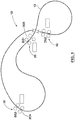
- one train system 10 comprises a track 12 having parallel rails 12a , 12b .
- a train 14 includes a first or lead car 16 having both forward and rear wheel pairs 18 , 20 operable on the track 12 for providing a free wheeling movement to the lead car.
- the train includes additional cars described as a second or rear car 22 and an intermediate car 24 or multiple intermediate cars carried between the lead and rear cars.
- the rear and intermediate cars 22 , 24 include a forward pivotal connection 26 for pivotally connecting the intermediate and rear cars to adjacent forward cars.
- the rear and intermediate cars 22 , 24 have only rear wheel pairs 20 operable on the track 12 for providing a free wheeling movement thereto.
- each of the cars has a side plate 28 affixed thereto.
- multiple drive stations 30 each have a variable frequency drive (VFD) including a drive tire 32 for frictionally contacting the side plate 28 and imparting a driven movement to each car and thus the train 14.
- VFD variable frequency drive
- the embodiment herein described includes each car having opposing side plates 28a , 28b and opposing drive tires 32a , 32b.
- each car may have a fixed side plate on each side, which runs the length of the car and spaced outside the wheels and tracks. These side plates may be located symmetrically with the wheels and parallel to the light rails.
- the side plates may be located asymmetrical with the wheels.
- the wheels are part of the side plates such that the sideplate-wheel arrangement allows the train to be moved either downstream or upstream.
- the wheels are placed to allow the train to operate in either an upright or an inverted position.
- Each drive stations 30 includes A/C inverters and a controller connected to every set of drive motors such that the motors may be synchronized through modifying of at least one of voltage and frequency thereto.
- Forward or reverse motion of the train is the result of horizontal rotation of tires on opposite sides of the train turning in opposite directions with suitable pressure of said rotation that provides minimal slip between the tire surface and side plates. In other words, the two opposing tires are both pushed inward toward the center of the track.
- the drive tires 32 are further adapted to engage and apply pressure to the side plate 28 of the car.
- horizontal drive station and vertical drive station arrangements are shown, respectively, according to embodiments of the present invention.
- this arrangement may be utilized for installations having restricted height clearances.
- the improvements of the horizontal drive station provide for a reduction of steel used in the system, improved manufacturability and, therefore, reduction in system component costs as compared to previous drive stations.
- the arrangement of the drive station separates the drive force and the squeeze force. In particular, the drive force is reacted at the pivot bearings 50 and the squeeze force is isolated to the rotating element, i.e. the drive tire 44.
- the support structure 42 of the horizontal drive station 40 also provides for improved maintainability and access to the drive tires 44.
- the support structure 42 provides a base for mounting the drive unit assembly 46. In most applications, the support structure 42 will be mounted to a frame 96 that transverses the parallel tracks 12a, 12b. In this arrangement, two support structures 42a, 42b are provided on either side of the parallel tracks 12a, 12b in order to allow two separate drive unit assemblies to engage opposite side plates of the car.
- the support structure 42 is typically made up of a base plate 94 to which two side plates 98a, 98b are attached perpendicular thereto ( Figure 6 ). Each side plate 98 being connected at one end to a mounting plate 92, which runs perpendicular to the side plate 98 and substantially parallel to the track 12.
- a bumper mount plate 100 is positioned parallel to the mounting plate 92 at the other end of the side plate 98. If present, a bumper 104 can be attached to the bumper mount plate 100 to minimize damage to the overall drive station 30, in the event a car is laterally thrust against the drive station while passing through.
- a pivot mount plate 102 is provided to cover the corner formed between the side plate 98 and the mounting plate 92.
- the drive unit assembly 46 includes at least one drive tire 44 which is coupled to a motor-gearbox arrangement 48 (e.g., an electro-mechanical drive having the appropriate horsepower rating to propel the train and an appropriate gear ratio to move it at a designated speed, and to meet the desired duty cycle) and is pivotably connected to the support structure 42 such that the unit 46 may pivot for maintenance (e.g., removal of tires or servicing of the drive).
- a motor-gearbox arrangement 48 e.g., an electro-mechanical drive having the appropriate horsepower rating to propel the train and an appropriate gear ratio to move it at a designated speed, and to meet the desired duty cycle
- Each drive unit 46 operates a drive tire 44 for frictionally contacting the side plate 28 of a car .
- An arrangement is provided to control the required opposing pressures to provide adequate forward or reverse thrust to move the train 14 without slipping.
- the plane at which the drive tire 44 pivots is changed in the horizontal drive station described herein as compared to prior drive stations. Changing this plane alters the way the reaction forces from the drive station thrust are carried to the support structure 42.
- the drive tire 44 described herein rotates on a plane parallel to the track 12.
- force is applied on a different plane than earlier systems, and the reaction force is separated out of the tensioning device.
- the drive force and squeeze forces are separated, wherein the drive force is reacted at the pivot bearings 50 and the squeeze force is isolated to the rotating element, i.e. the drive tire 44.
- the normal (squeeze) force can be reacted through a spring element 52 which is designed to maintain the required force over a wider range of travel.
- the pivot bearings 50 are attached to the pivot mount plate 102 of the support structure 42.
- the spring element 52 is provided as an air spring arrangement, which may be used to control such pressure (i.e., squeeze force) required between the tire 44 and side plate 28 of the train 14 (e.g., to adjust the tire/car engagement to account for tire wear and fabrication tolerances) ( Figure 7 ).
- the spring element 52 can include a housing 58 for the air spring 82.
- the internal volume of the housing 58 can be adjusted by lengthening or shortening posts 84 in order to expand or compress the air spring 82.
- the spring element 52 is attached to support structure 42 in a location that allows pressure to be applied to the drive mounting plate 54, which ultimately results in the drive tire 44 being squeezed against the side plate 28.
- the spring element 52 rests on the base plate 94 of the support structure 42 and is attached to the mounting plate 92 of the support structure 42.
- two spring elements 52a, 52b are used in each support structure 42, one mounted on each mounting plate 92. This arrangement allows for substantially even lateral force to be applied to the drive mounting plate 54 in the vicinity of the drive tire 44.
- the drive unit 46 can be pivoted from an active position where the drive tire 44 is positioned in a plane parallel to the track 12 to a inactive position where the drive tire 44 is positioned in a plane that is perpendicular to the track 12.
- the drive unit assembly 46 including the drive unit mounting plate 54, is pivoted through pivot bearings 50 positioned on the support structure 42.
- a tire harness 158 can be used to secure the drive tire 44 during pivoting of the assembly 46 and maintenance thereof ( Figure 8 ).
- the drive unit assembly 46 can be stabilized (i.e. prevented from pivoting back into the active position) by inserting and securing support rods 72 to the mounting plate 54.
- the support rods 72 are inserted through hollow support pegs 74 connected to the mounting plate 54.
- the support pegs 74 are provided to allow for the mounting plate 54 and associated drive unit assembly 46 to be positioned away from the support structure 42 when in the active position.
- the support structure 62 of the vertical drive station 60 is preferably a steel structure rather than a cement foundation.
- the support structure 62 as shown is also more robust, while using less steel as compared to traditional systems.
- the support structure 62 is shown to be formed using a laser cut/bent steel plate design (see FIG. 10 ) instead of a structural member based design as used in traditional systems.
- the vertical drive station 60 also provides for improved maintainability and access to the drive tires 64.
- the drive unit assembly 66 including a drive tires 64 are coupled to a motor-gearbox arrangement, as described above, via a drive mounting plate 68.
- the drive unit 46 may be a hydrodynamic device as shown having a fluid coupling arrangement 142 ( FIG. 11 ).
- Either one of the drive unit 66 or the drive mounting plate 68 includes engagement points, such as eyelets 56, for hoisting the unit for maintenance (e.g., replacement of tires or servicing of the drive).
- Each drive unit 66 operates a drive tire 64 for frictionally contacting the side plate 28 of a car.
- An arrangement is provided to control the required opposing pressures to provide adequate forward or reverse thrust to move the train 14 without slipping.
- a plurality of apertures 70 are preformed in the drive unit mounting plate 68 ( FIG. 12b ) for selective adjustment to control such pressure required between the tire 64 and side plates 28 of the car by mounting the drive tire 64 in selective proximity to the side plates 28 of the car (e.g., to adjust the tire/car engagement to account for tire wear).
- Selective adjustment to control pressure between the tire 64 and side plates 28 of the car is achieved by providing a plurality of apertures 70 preformed on the drive unit mounting plate 68 ( FIG. 12b ) and a corresponding number of apertures 80 on the support structure 62 ( FIG. 10 ).
- the plurality of apertures 70 preformed on the drive unit mounting plate 68 are typically parallel to the edge of the mounting plate 68 distal to the track 12, whereas a corresponding number of apertures 80 are preformed on the support structure 62 and are offset from the edge of the support structure 62 distal to the track 12.
- the drive unit mounting plate 68 and support structure 62 are preformed on the drive unit mounting plate 68 and support structure 62, respectively, at opposite ends of the plate 68 and support structure 62 along the edges distal to the track 12.
- the tire 64 can be incrementally positioned closer to the track 12, and by extension the side plate 28 of the car, by connecting the mounting plate 68 to the support structure 62 though one of the apertures 70 in the mounting plate 68 and the corresponding aperture 80 in the support structure 62 at a position that urges the mounting plate 68 closer to the track 12.
- the mounting plate 68 is connected to the support structure 62 by inserting a pin 76 through the corresponding apertures 70, 80 in the mounting plate 68 and support structure 62.
- the various components of the drive units 46, 66 may be optimized to provide the proper friction required between the drive tire 44, 64 and side plate 28 of the car.
- the frictional forces of these drive tires-side drive plate contact is optimized to avoid slippage between the drive tires 44, 64 and side plates 28, hence providing forward thrust.
- the surface of the side plate(s) 28 of the car may be adapted to improve such engagement with the drive tire 44, 64 (e.g., side plate material may be modified or a coating may be applied to the side plate).
- various specifications of the drive tire 44, 64 e.g., tire pressure, composition, durometer, spring rate, etc.
- Flexible drive tires 44, 64 may be made out of a variety of materials. Examples of suitable material, but not limited to, are soft solid tires, synthetic rubber tires, urethane pneumatic rubber tires and synthetic foam filled tires.
- the preferred tire 44, 64 is a foam filled pneumatic tire. Foam provides the flex function associated with air filled tires without the potential problem of rapid deflation. The flexing capability compensates for irregularities in side plate 28 spacing and also allowed for full contact of straight side plates 28 even in deformed sections that would lead to contact skips with nonflexible tires. The use of a deflatable tire could cause a loss of traction and offer potential for derailment. As provided in earlier systems, it was desired to have a low durometer for the drive tire 44, 64. In this way, the face of the foam filled tire would sufficiently spread (or sufficiently deform) upon contact with the side plate of the train to provide sufficient squeeze force to move the train.
- the braking device may be in the form of a dynamic braking arrangement to prevent train 14 runaway on downhill runs and with positive locking brakes that are actuated in power off situations that can hold a train in place until the system can be returned to an operational status.
- braking may be achieved by two systems.
- a service braking arrangement is provided through the motor control system, which dynamically brakes the drives 48 using the motors. In this arrangement, the braking effort is controlled by limiting or eliminating current to the drive unit assembly.
- a mechanical braking system is provided in the form of a hydraulic release arrangement, which is installed as an extension of an intermediate shaft of the gearbox.
- This mechanical braking system may be utilized for holding and emergency situations.
- both forms of braking systems can be included in the drive stations 40, 60 to provide redundancy in the system in the event of failure of one of the systems.
Landscapes
- Engineering & Computer Science (AREA)
- Mechanical Engineering (AREA)
- Transportation (AREA)
- Chemical & Material Sciences (AREA)
- Combustion & Propulsion (AREA)
- Physics & Mathematics (AREA)
- General Physics & Mathematics (AREA)
- Automation & Control Theory (AREA)
- Architecture (AREA)
- Civil Engineering (AREA)
- Structural Engineering (AREA)
- Platform Screen Doors And Railroad Systems (AREA)
- Control Of Conveyors (AREA)
- Machines For Laying And Maintaining Railways (AREA)
- Tires In General (AREA)
- Electric Propulsion And Braking For Vehicles (AREA)
- Chutes (AREA)
- Control Of Position, Course, Altitude, Or Attitude Of Moving Bodies (AREA)
- Ship Loading And Unloading (AREA)
- Control Of Vehicles With Linear Motors And Vehicles That Are Magnetically Levitated (AREA)
- Loading Or Unloading Of Vehicles (AREA)
- Handcart (AREA)
- Arrangement Or Mounting Of Propulsion Units For Vehicles (AREA)
- Structure Of Belt Conveyors (AREA)
- Current-Collector Devices For Electrically Propelled Vehicles (AREA)
- Leg Units, Guards, And Driving Tracks Of Cranes (AREA)
- Carriers, Traveling Bodies, And Overhead Traveling Cranes (AREA)
- Body Structure For Vehicles (AREA)
- Linear Motors (AREA)
- Guiding Agricultural Machines (AREA)
- Mutual Connection Of Rods And Tubes (AREA)
- Train Traffic Observation, Control, And Security (AREA)
- Branching, Merging, And Special Transfer Between Conveyors (AREA)
- Filling Or Emptying Of Bunkers, Hoppers, And Tanks (AREA)
Abstract
Description
- This application claims priority to
U.S. provisional application No. 62/021,905 - The present invention generally relates to a rail transport system having no internal drive, and in particular to drive station arrangements for moving cars through the rail transport system.
- Methods and arrangements for moving bulk materials in conventional trains, trucks, conveyor belts, aerial tramways or as a slurry in a pipeline are well known and are typically used in various industries because of site-specific needs or experience. In the minerals and aggregate industries, for example, bulk materials are moved from mining or extraction sites to a process facility for upgrading or sizing. Trucks had been the system of choice for many years for moving bulk materials. Trucks were enlarged for off-road vehicles because of their efficient transport of bulk materials and increased capacity. These vehicles, however, are limited to site specific applications and are provided at a high capital cost. Major off-road trucks have evolved that require very wide roadways for passing each other, are not energy efficient per ton-mile of material transported, have limited hill climbing ability, and are dangerous because of potential of operator error as well as being environmentally unpleasant neighbors.
- Trains have been used for many years for bulk material transport in hopper cars. Because of low friction, the use of free rolling iron or steel wheels on steel tracks they are very efficient users of energy but are limited in capacity relative to the drivers or locomotives required. Large tonnage long trains use multiple drivers that are heavy units, which dictate the weight of rail and ballast requirements. All railroads must be designed for the weight of the drivers or locomotives included fuel, not the combination of car plus loads, which are significantly less. The drivers need to be of sufficient weight so that the rotary drive tire makes contact with the stationary rail and must have sufficient friction to produce forward or reverse movement of what will include heavily loaded cars. The inclination capable of conventional railroad systems is limited to the friction between the weighted drive wheels and track. Rail cars are individual units that each has to be loaded in a batch process, one car at a time. Bulk materials can be unloaded from hopper cars by opening bottom dump hatches or can be individually rotated to dump out of the top. Spotting cars for both loading and unloading is time consuming and labor intensive.
- Although moving from one location to another may be cost effective, the added cost of batch loading and unloading stages in shorter distance transports reduces the rail transport cost effectiveness. With normal single dual track train systems only one train can be used on a system at a time.
- Conveyor belts have been used for many years to move bulk materials. A wide variety of conveyor belt systems exist that can move practically every conceivable bulk material. Very long distance single belt runs are very capital cost intensive and are subject to catastrophic failure when a belt tears or rips, typically shutting down the entire system and dumping the carried load, requiring cleanup. Conveyor belts are relatively energy efficient but can require high maintenance because of an inherent problem of multiple idler bearings requiring constant checking and replacement. Short distance conveyor belts are commonly used in dry or clamp transport of almost all types of materials. Because conveyor belts are very flexible and desirably operated over fairly flat terrain, they are not efficient at transporting moderately high solids slurry where water and fines can accumulate in low spots and spill over the side creating wet spilled slurry handling problems.
- Some bulk materials can be transported in pipelines when mixed with water to form slurry that is pushed or pulled with a motor driven pump impeller in an airless or flooded environment. The size of the individual particles that are present in the bulk materials dictates the transport speed necessary to maintain movement. For example, if large particles are present then the velocity must be high enough to maintain movement by saltation or skidding along the bottom of the pipe of the very largest particles. Because pipelines operate in a dynamic environment, friction is created with the stationary pipe wall by a moving fluid and solid mass. The higher the speed of the moving mass the higher the friction loss at the wall surface requiring increased energy to compensate. Depending on the application, the bulk material has to be diluted with water initially to facilitate transport and dewatering at the discharge end.
- Light rail, narrow gage railroads for transporting bulk material from mines and the like is known as described by way of example with reference to
U.S. Pat. No. 3,332,535 to Hubert et al. wherein a light rail train made up of several cars is propelled by drive wheels and electric motors combinations, dumping over an outside loop. By way of further example,U.S. Pat. No. 3,752,334 to Robinson, Jr. et al. discloses a similar narrow gage railroad wherein the cars are driven by an electric motor and drive wheels.U.S. Pat. No. 3,039,402 to Richardson describes a method of moving railroad cars using a stationary friction drive tire. - While the above described transport systems and methods have specific advantages over conventional systems, each is highly dependent upon a specific application. It has become apparent that increases in labor, energy and material costs plus environmental concerns that alternate transport methods need to be applied that are energy and labor efficient, quiet, non-polluting, and esthetically unobtrusive. US Patent Publications
US 2003/0226470 to Dibble et al. for "Rail Transport System for Bulk Materials",US 2006/0162608 to Dibble for "Light Rail Transport System for Bulk Materials", andU.S. Pat. No. 8,140,202 to Dibble describe a light rail train utilizing an open semi-circular trough train with drive stations, the disclosures of which are herein incorporated by reference in their entirety. Such a light rail system offers an innovative alternative to the above mentioned material transport systems and provides for the transport of bulk materials using a plurality of connected cars open at each end except for the first and last cars, which have end plates. The train forms a long open trough and has a flexible flap attached to each car and overlapping the car in front to prevent spillage during movement. The lead car has four wheels and tapered side drive plates in the front of the car to facilitate entry into the drive stations. The cars that follow have two wheels with a clevis hitch connecting the front to the rear of the car immediately forward. Movement of the train is provided by a series of appropriately placed drive stations having drive motors on either side of the track which are AC electric motors with drive means such as tires to provide frictional contact with the side drive plates. At each drive station, each drive motor is connected to an AC inverter and controller for drive control, with both voltage and frequency being modified as needed. The electric motors each turn a tire in a horizontal plane that physically contacts two parallel side drive plates external of the wheels of each car. Pressure on the side drive plates by these drive tires converts the rotary motion of the tires into horizontal thrust. The wheels on the cars are spaced to allow operation in an inverted position by use of a double set of rails to allow the cars to hang upside down for unloading. By rotating this double track system the unit train can be returned to its normal operating condition. Such a system is well known and commercially referred to as the Rail-Veyor™ material handling system. - Flanged wheels may be symmetrical to the side drive plates allowing operation in an inverted position which, when four rails are used to encapsulate the wheel outside loop discharge of the bulk material is possible. By using elevated rails, the train can operate in the inverted position as easily as in the convention manner.
- Yet further, drives for such light rail systems have been developed as described in
U.S. Pat. No. 5,067,413 to Kiuchi et al. describing a device for conveying travelable bodies which are provided no driving source, on a fixed path. A plurality of travelable bodies travels on the fixed path while aligned substantially in close contact with each other. Traveling power is transmitted to one of a plurality of travelable bodies which is positioned on at least one end of the alignment. The traveling power drives the travelable body with frictional force while pressing one side surface of the travelable body, and is transmitted to the travelable body while backing up the other side surface of the travelable body. A device to transmit traveling power is arranged on only a part of the fixed path. - While light rail systems such as the Rail-Veyor™ material handling system above described are generally accepted, there is a need to provide an improved system having high efficiency and reliability with regard to controlling the movement of the train and in particular multiple trains with the bulk material transport system. The present invention is also directed to an improved system and method for controlling such light rail systems in an efficient and reliable manner.
- The present invention generally relates to a rail transport system having no internal drive, and in particular to an improved rail transport system for conveying bulk materials. The rail transport system includes improvements in functionality, manufacturability and, therefore, reduction in system component costs. The rail transport system further includes drive system arrangements that include improvements in reliability and functionality.
- According to an aspect of the present invention, there is provided a drive assembly for a rail transport system for conveying bulk materials via a plurality of cars adapted to form a train, each car having a pair of side drive plates and a trough arrangement for carrying the bulk materials on a rail. The drive assembly comprising: a support structure, at least one drive unit connected to the support structure. The drive unit including a drive tire adapted to frictionally contact a side drive plate of at least one of the cars for imparting a driven moment to the car. The drive assembly further comprising a spring element operatively located between the support and the drive unit to control squeeze force between the contacting drive tire and side plate of the car. The drive unit is further adapted to pivot at the connection to the support structure on a plane parallel to the track such that drive force is reacted at the connection between the drive unit and the support and squeeze force is reacted through the spring element.
- In one embodiment, the drive unit is pivotably connected to the support structure such that the drive tires are accessible for maintenance therefor.
- In another embodiment, the drive force is reacted at a pivot bushing connecting the drive unit to the support structure.
- In a further embodiment, the spring element is an air spring arrangement to control the squeeze force between the drive tire and the side drive plates.
- In a still further embodiment, the drive assembly further comprises a frame for supporting the support structure relative to the rail.
- According to another aspect of the present invention, there is provided a drive assembly for a rail transport system for conveying bulk materials via a plurality of cars adapted to form a train, each car having a pair of side drive plates and a trough arrangement for carrying the bulk materials on a rail. The drive assembly comprising: a support structure, and at least one drive tire for frictionally contacting the side drive plates of at least some of the cars for imparting a driven moment to each car. The drive tire being pivotally connected to the support structure such that the drive tires are accessible for maintenance therefor.
- In one embodiment, the drive force is reacted at the pivot connection.
- In another embodiment, the drive force is reacted at a pivot bushing connecting the drive tire to the support structure.
- In a further embodiment, the drive unit further comprises a frame for supporting the support structure relative to the rail.
- According to further aspect of the present invention, there is provided a drive assembly for a rail transport system for conveying bulk materials via a plurality of cars adapted to form a train, each car having a pair of side drive plates and a trough arrangement for carrying the bulk materials on a rail. The drive assembly comprising: at least one drive unit comprising a motor and a drive tire. The motor being adapted to rotate the drive tire to frictionally contact a side drive plate of at least one of the cars for imparting a driven moment to the car. The drive assembly further comprising a mounting plate situated between the motor and the drive tire, and a support structure adapted to carry the mounting plate such that drive force from the drive unit and squeeze force between the drive tire and side plate are reacted through the mounting plate to the support structure.
- In one embodiment, the mounting plate further comprises an engagement for allowing hoisting of the drive unit from the support structure.
- In another embodiment, the drive unit further comprises an engagement for allowing hoisting of the drive unit from the support structure.
- In a further embodiment, the mounting plate comprises a mounting engagement for selectively adjusting the proximity of the drive tire to the side plate for selective control of squeeze pressure between the drive tire and the side plate.
- In a still further embodiment, the mounting plate defines a plurality of apertures. The control of squeeze pressure is being capable of selective adjustment by affixing the mounting plate to the support system via a pin arrangement relative to one of the apertures of the mounting plate.
- In a yet further embodiment, the drive assembly further comprises a base for supporting the support structure relative to the rail.
- In any of the embodiments described above the drive assembly can further comprises a dynamic braking arrangement for limiting rotation of the drive tire. The braking effort of the dynamic braking arrangement being controlled by limiting current to the drive unit assembly.
- In a further embodiment of any of the embodiments described above, the drive assembly can further comprises a mechanical braking arrangement for limiting rotation of the drive tire. The mechanical braking arrangement being a hydraulic release type arrangement.
- Various embodiments of the invention are described by way of example with reference to the accompanying drawings and appendices. The present invention will be apparent to those skilled in the art by reading the following detailed description of various embodiments thereof, with reference to the attached drawings, in which:
-
FIG. 1 is a diagrammatical illustration of one rail system in keeping with the teachings of the present invention; -
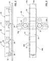
FIGS. 2 and 3 are side and top plan views, respectively, of one embodiment of a train operable with the system ofFIG. 1 ; -
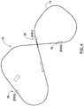
FIG. 4 is a diagrammatical illustration of a track arrangement operable with a control system of the present invention; -
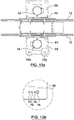
FIG. 5 is a diagrammatical illustration of (a) a horizontal drive station, (b) an isolated view of the spring element, and (c) an isolated view of the pivot bearing, all according to embodiments of the present invention; -
FIG. 6 is a perspective view of the support structure of the horizontal drive station according to an embodiment of the present invention; -
FIG. 7 is a perspective view of the spring element according to an embodiment of the present invention; -
FIG. 8 is a diagrammatical illustration of (a) the drive assembly in an inactive position, and (b) an isolated view of the support posts, all according to embodiments of the present invention; -
FIG. 9 is a perspective view of a vertical drive station according to an embodiment of the present invention; -
FIG. 10 is a perspective view of a support structure for use in a vertical drive station according to an embodiment of the present invention; -
FIG. 11 is a perspective view of a drive unit assembly for use in a vertical drive station according to an embodiment of the present invention; and -
FIG. 12 is (a) a top plan view of the vertical drive station, and (b) an isolated view of the apertures of the mounting plate, both according to embodiments of the present invention. - The present invention will now be described more fully hereinafter with reference to the accompanying drawings and appendices, in which embodiments of the invention are shown. This invention may, however, be embodied in many different forms and should not be construed as limited to the embodiments set forth herein. Rather, the embodiments herein presented are provided so that this disclosure will be thorough and complete, and will fully convey the scope of the invention to those skilled in the art.
- With reference initially to
FIGS. 1-3 , onetrain system 10, in keeping with the teachings of the present invention, comprises atrack 12 havingparallel rails train 14 includes a first orlead car 16 having both forward and rear wheel pairs 18, 20 operable on thetrack 12 for providing a free wheeling movement to the lead car. For the embodiment herein described by way of example, the train includes additional cars described as a second orrear car 22 and anintermediate car 24 or multiple intermediate cars carried between the lead and rear cars. The rear andintermediate cars pivotal connection 26 for pivotally connecting the intermediate and rear cars to adjacent forward cars. The rear andintermediate cars track 12 for providing a free wheeling movement thereto. - With continued reference to
FIG. 2 , each of the cars has aside plate 28 affixed thereto. With reference toFIGS. 1 ,3-4 ,multiple drive stations 30 each have a variable frequency drive (VFD) including adrive tire 32 for frictionally contacting theside plate 28 and imparting a driven movement to each car and thus thetrain 14. As illustrated with continued reference toFIG. 3 , the embodiment herein described includes each car having opposingside plates drive tires drive stations 30 includes A/C inverters and a controller connected to every set of drive motors such that the motors may be synchronized through modifying of at least one of voltage and frequency thereto. Forward or reverse motion of the train is the result of horizontal rotation of tires on opposite sides of the train turning in opposite directions with suitable pressure of said rotation that provides minimal slip between the tire surface and side plates. In other words, the two opposing tires are both pushed inward toward the center of the track. In order the stop the train, thedrive tires 32 are further adapted to engage and apply pressure to theside plate 28 of the car. - Referring to
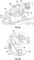
FIGS. 5-12 , horizontal drive station and vertical drive station arrangements are shown, respectively, according to embodiments of the present invention. Referring first to thehorizontal drive station 40 design ofFIG. 5 , this arrangement may be utilized for installations having restricted height clearances. The improvements of the horizontal drive station provide for a reduction of steel used in the system, improved manufacturability and, therefore, reduction in system component costs as compared to previous drive stations. Moreover, the arrangement of the drive station separates the drive force and the squeeze force. In particular, the drive force is reacted at thepivot bearings 50 and the squeeze force is isolated to the rotating element, i.e. thedrive tire 44. Thesupport structure 42 of thehorizontal drive station 40 also provides for improved maintainability and access to thedrive tires 44. - The
support structure 42 provides a base for mounting thedrive unit assembly 46. In most applications, thesupport structure 42 will be mounted to a frame 96 that transverses theparallel tracks support structures parallel tracks - In order to the accommodate the
drive unit assembly 46, thesupport structure 42 is typically made up of abase plate 94 to which twoside plates Figure 6 ). Eachside plate 98 being connected at one end to a mountingplate 92, which runs perpendicular to theside plate 98 and substantially parallel to thetrack 12. In some applications, abumper mount plate 100 is positioned parallel to the mountingplate 92 at the other end of theside plate 98. If present, abumper 104 can be attached to thebumper mount plate 100 to minimize damage to theoverall drive station 30, in the event a car is laterally thrust against the drive station while passing through. In order to accommodate the pivot bearing 50 of thedrive unit assembly 46, apivot mount plate 102 is provided to cover the corner formed between theside plate 98 and the mountingplate 92. - The
drive unit assembly 46 includes at least onedrive tire 44 which is coupled to a motor-gearbox arrangement 48 (e.g., an electro-mechanical drive having the appropriate horsepower rating to propel the train and an appropriate gear ratio to move it at a designated speed, and to meet the desired duty cycle) and is pivotably connected to thesupport structure 42 such that theunit 46 may pivot for maintenance (e.g., removal of tires or servicing of the drive). Eachdrive unit 46 operates adrive tire 44 for frictionally contacting theside plate 28 of a car . An arrangement is provided to control the required opposing pressures to provide adequate forward or reverse thrust to move thetrain 14 without slipping. - Furthermore, the plane at which the
drive tire 44 pivots is changed in the horizontal drive station described herein as compared to prior drive stations. Changing this plane alters the way the reaction forces from the drive station thrust are carried to thesupport structure 42. - Specifically, earlier systems included a threaded rod which was used to pull the drive tire in by pivoting the entire drive into the train. In this arrangement, the normal (squeeze) force and the reactive thrust force are both carried as tension in the threaded rod.
- Instead of the drive tire moving vertically with reference to the ground in prior drive stations, the
drive tire 44 described herein rotates on a plane parallel to thetrack 12. In this arrangement, force is applied on a different plane than earlier systems, and the reaction force is separated out of the tensioning device. Specifically, the drive force and squeeze forces are separated, wherein the drive force is reacted at thepivot bearings 50 and the squeeze force is isolated to the rotating element, i.e. thedrive tire 44. In this way, the normal (squeeze) force can be reacted through aspring element 52 which is designed to maintain the required force over a wider range of travel. Typically, thepivot bearings 50 are attached to thepivot mount plate 102 of thesupport structure 42. - In one embodiment, the
spring element 52 is provided as an air spring arrangement, which may be used to control such pressure (i.e., squeeze force) required between thetire 44 andside plate 28 of the train 14 (e.g., to adjust the tire/car engagement to account for tire wear and fabrication tolerances) (Figure 7 ). As shown in the embodiment ofFigure 7 , thespring element 52 can include ahousing 58 for theair spring 82. The internal volume of thehousing 58 can be adjusted by lengthening or shorteningposts 84 in order to expand or compress theair spring 82. Thespring element 52 is attached to supportstructure 42 in a location that allows pressure to be applied to thedrive mounting plate 54, which ultimately results in thedrive tire 44 being squeezed against theside plate 28. In one embodiment, thespring element 52 rests on thebase plate 94 of thesupport structure 42 and is attached to the mountingplate 92 of thesupport structure 42. Generally, twospring elements support structure 42, one mounted on each mountingplate 92. This arrangement allows for substantially even lateral force to be applied to thedrive mounting plate 54 in the vicinity of thedrive tire 44. - As mentioned above, to allow for maintenance of the drive tire(s) 44, the
drive unit 46 can be pivoted from an active position where thedrive tire 44 is positioned in a plane parallel to thetrack 12 to a inactive position where thedrive tire 44 is positioned in a plane that is perpendicular to thetrack 12. Thedrive unit assembly 46, including the driveunit mounting plate 54, is pivoted throughpivot bearings 50 positioned on thesupport structure 42. To improve worker safety during maintenance of thedrive assembly 46, atire harness 158 can be used to secure thedrive tire 44 during pivoting of theassembly 46 and maintenance thereof (Figure 8 ). - When in the inactive position, the
drive unit assembly 46 can be stabilized (i.e. prevented from pivoting back into the active position) by inserting and securingsupport rods 72 to the mountingplate 54. In one embodiment, thesupport rods 72 are inserted through hollow support pegs 74 connected to the mountingplate 54. The support pegs 74 are provided to allow for the mountingplate 54 and associateddrive unit assembly 46 to be positioned away from thesupport structure 42 when in the active position. - Referring now to the
vertical drive station 60 design shown inFIG. 9 , this arrangement may be utilized for installations having no height clearance restrictions. The improvements of thevertical drive station 60 provide for a reduction of steel used in the system, improved manufacturability and, therefore, reduction in system component costs. Thesupport structure 62 of thevertical drive station 60 is preferably a steel structure rather than a cement foundation. Thesupport structure 62 as shown is also more robust, while using less steel as compared to traditional systems. Specifically, thesupport structure 62 is shown to be formed using a laser cut/bent steel plate design (seeFIG. 10 ) instead of a structural member based design as used in traditional systems. Thevertical drive station 60 also provides for improved maintainability and access to thedrive tires 64. Specifically, thedrive unit assembly 66 including adrive tires 64 are coupled to a motor-gearbox arrangement, as described above, via adrive mounting plate 68. In yet another arrangement, thedrive unit 46 may be a hydrodynamic device as shown having a fluid coupling arrangement 142 (FIG. 11 ). Either one of thedrive unit 66 or thedrive mounting plate 68 includes engagement points, such aseyelets 56, for hoisting the unit for maintenance (e.g., replacement of tires or servicing of the drive). Eachdrive unit 66 operates adrive tire 64 for frictionally contacting theside plate 28 of a car. An arrangement is provided to control the required opposing pressures to provide adequate forward or reverse thrust to move thetrain 14 without slipping. Specifically, a plurality of apertures 70 are preformed in the drive unit mounting plate 68 (FIG. 12b ) for selective adjustment to control such pressure required between thetire 64 andside plates 28 of the car by mounting thedrive tire 64 in selective proximity to theside plates 28 of the car (e.g., to adjust the tire/car engagement to account for tire wear). - Selective adjustment to control pressure between the
tire 64 andside plates 28 of the car is achieved by providing a plurality of apertures 70 preformed on the drive unit mounting plate 68 (FIG. 12b ) and a corresponding number ofapertures 80 on the support structure 62 (FIG. 10 ). The plurality of apertures 70 preformed on the driveunit mounting plate 68 are typically parallel to the edge of the mountingplate 68 distal to thetrack 12, whereas a corresponding number ofapertures 80 are preformed on thesupport structure 62 and are offset from the edge of thesupport structure 62 distal to thetrack 12. Generally two sets ofapertures unit mounting plate 68 andsupport structure 62, respectively, at opposite ends of theplate 68 andsupport structure 62 along the edges distal to thetrack 12. Thetire 64 can be incrementally positioned closer to thetrack 12, and by extension theside plate 28 of the car, by connecting the mountingplate 68 to thesupport structure 62 though one of the apertures 70 in the mountingplate 68 and the correspondingaperture 80 in thesupport structure 62 at a position that urges the mountingplate 68 closer to thetrack 12. In one embodiment, the mountingplate 68 is connected to thesupport structure 62 by inserting apin 76 through the correspondingapertures 70, 80 in the mountingplate 68 andsupport structure 62. - The various components of the
drive units drive tire side plate 28 of the car. The frictional forces of these drive tires-side drive plate contact is optimized to avoid slippage between thedrive tires side plates 28, hence providing forward thrust. In one example, the surface of the side plate(s) 28 of the car may be adapted to improve such engagement with thedrive tire 44, 64 (e.g., side plate material may be modified or a coating may be applied to the side plate). In another example, various specifications of thedrive tire 44, 64 (e.g., tire pressure, composition, durometer, spring rate, etc.) may be made to modify the frictional forces between thedrive tires side plate 28 of the car.Flexible drive tires preferred tire side plate 28 spacing and also allowed for full contact ofstraight side plates 28 even in deformed sections that would lead to contact skips with nonflexible tires. The use of a deflatable tire could cause a loss of traction and offer potential for derailment. As provided in earlier systems, it was desired to have a low durometer for thedrive tire - The
horizontal drive station 40 andvertical drive stations 60 as shown inFIGS. 5 and9 , respectively, include a braking device coupled to the motor-gearbox arrangement 48. The braking device may be in the form of a dynamic braking arrangement to preventtrain 14 runaway on downhill runs and with positive locking brakes that are actuated in power off situations that can hold a train in place until the system can be returned to an operational status. Generally, braking may be achieved by two systems. In one embodiment, a service braking arrangement is provided through the motor control system, which dynamically brakes thedrives 48 using the motors. In this arrangement, the braking effort is controlled by limiting or eliminating current to the drive unit assembly. In another embodiment, a mechanical braking system is provided in the form of a hydraulic release arrangement, which is installed as an extension of an intermediate shaft of the gearbox. This mechanical braking system may be utilized for holding and emergency situations. Moreover, both forms of braking systems can be included in thedrive stations - Many modifications and other embodiments of the inventions set forth herein will come to mind to one skilled in the art to which these inventions pertain having the benefit of the teachings presented in the foregoing descriptions and the associated drawings. Therefore, it is to be understood that the inventions are not to be limited to the specific examples of the embodiments disclosed and that modifications and other embodiments are intended to be included within the scope of the appended claims. Although specific terms are employed herein, they are used in a generic and descriptive sense only and not for purposes of limitation.
Claims (13)
- A drive assembly for a rail transport system for conveying bulk materials via a plurality of cars adapted to form a train, each car having a pair of side drive plates and a trough arrangement for carrying the bulk materials on a rail, said drive assembly comprising:a support structure,at least one drive unit connected to the support structure, said drive unit including a drive tire adapted to frictionally contact a side drive plate of at least one of the cars for imparting a driven moment to the car, anda spring element operatively located between the support and the drive unit to control squeeze force between the contacting drive tire and side plate of the car,wherein the drive unit is further adapted to pivot at the connection to the support structure on a plane parallel to the track such that drive force is reacted at the connection between the drive unit and the support and squeeze force is reacted through the spring element.
- The drive assembly of claim 1, wherein the drive unit is pivotably connected to the support structure such that the drive tires are accessible for maintenance therefor.
- The drive assembly of claim 1, wherein the drive force is reacted at a pivot bushing connecting the drive unit to the support structure.
- The drive assembly of claim 1, wherein the spring element is an air spring arrangement to control the squeeze force between the drive tire and the side drive plates.
- The drive assembly of claim 1, further comprising a base for supporting the support structure relative to the rail.
- A drive assembly for a rail transport system for conveying bulk materials via a plurality of cars adapted to form a train, each car having a pair of side drive plates and a trough arrangement for carrying the bulk materials on a rail, said drive assembly comprising:a support structure, andat least one drive tire for frictionally contacting the side drive plates of at least some of the cars for imparting a driven moment to each car, said drive tire being pivotally connected to the support structure such that the drive tires are accessible for maintenance therefor.
- The drive assembly of claim 6, wherein the drive force is reacted at the pivot connection.
- The drive assembly of claim 7, wherein the drive force is reacted at a pivot bushing connecting the drive tire to the support structure.
- The drive assembly of claim 6, further comprising a base for supporting the support structure relative to the rail.
- The drive assembly of any one of claims 1 to 9, further comprising a dynamic braking arrangement for limiting rotation of the drive tire.
- The drive assembly of any one of claims 1 to 9, further comprising a mechanical braking arrangement for limiting rotation of the drive tire.
- The drive assembly of claim 10, wherein braking effort of the dynamic braking arrangement is controlled by limiting current to the drive unit assembly.
- The drive assembly of claim 11, wherein the mechanical braking arrangement is a hydraulic release type arrangement.
Applications Claiming Priority (3)
| Application Number | Priority Date | Filing Date | Title |
|---|---|---|---|
| US201462021905P | 2014-07-08 | 2014-07-08 | |
| PCT/CA2015/050251 WO2016004516A1 (en) | 2014-07-08 | 2015-03-31 | Drive station arrangements |
| EP15819203.9A EP3166834B1 (en) | 2014-07-08 | 2015-03-31 | Drive station arrangements |
Related Parent Applications (2)
| Application Number | Title | Priority Date | Filing Date |
|---|---|---|---|
| EP15819203.9A Division-Into EP3166834B1 (en) | 2014-07-08 | 2015-03-31 | Drive station arrangements |
| EP15819203.9A Division EP3166834B1 (en) | 2014-07-08 | 2015-03-31 | Drive station arrangements |
Publications (3)
| Publication Number | Publication Date |
|---|---|
| EP3650302A1 true EP3650302A1 (en) | 2020-05-13 |
| EP3650302C0 EP3650302C0 (en) | 2023-06-07 |
| EP3650302B1 EP3650302B1 (en) | 2023-06-07 |
Family
ID=55063433
Family Applications (5)
| Application Number | Title | Priority Date | Filing Date |
|---|---|---|---|
| EP15818708.8A Active EP3169574B1 (en) | 2014-07-08 | 2015-03-09 | Control system for an improved rail transport system for conveying bulk materials |
| EP15819203.9A Active EP3166834B1 (en) | 2014-07-08 | 2015-03-31 | Drive station arrangements |
| EP19217743.4A Active EP3650302B1 (en) | 2014-07-08 | 2015-03-31 | Drive station arrangements |
| EP15818811.0A Active EP3166835B1 (en) | 2014-07-08 | 2015-03-31 | Support frames and rail cars for conveying bulk materials on a rail transport system |
| EP15819223.7A Active EP3167120B1 (en) | 2014-07-08 | 2015-03-31 | Rail transport dump loop system for conveying bulk materials |
Family Applications Before (2)
| Application Number | Title | Priority Date | Filing Date |
|---|---|---|---|
| EP15818708.8A Active EP3169574B1 (en) | 2014-07-08 | 2015-03-09 | Control system for an improved rail transport system for conveying bulk materials |
| EP15819203.9A Active EP3166834B1 (en) | 2014-07-08 | 2015-03-31 | Drive station arrangements |
Family Applications After (2)
| Application Number | Title | Priority Date | Filing Date |
|---|---|---|---|
| EP15818811.0A Active EP3166835B1 (en) | 2014-07-08 | 2015-03-31 | Support frames and rail cars for conveying bulk materials on a rail transport system |
| EP15819223.7A Active EP3167120B1 (en) | 2014-07-08 | 2015-03-31 | Rail transport dump loop system for conveying bulk materials |
Country Status (22)
| Country | Link |
|---|---|
| US (4) | US10926781B2 (en) |
| EP (5) | EP3169574B1 (en) |
| CN (5) | CN106715235B (en) |
| AP (4) | AP2017009738A0 (en) |
| AU (11) | AU2015286189B9 (en) |
| BR (2) | BR112017000446B1 (en) |
| CA (6) | CA2954240C (en) |
| CL (3) | CL2017000047A1 (en) |
| DK (1) | DK3166834T3 (en) |
| DO (3) | DOP2017000007A (en) |
| EA (6) | EA034827B1 (en) |
| ES (4) | ES2952392T3 (en) |
| HU (1) | HUE049165T2 (en) |
| MA (2) | MA40401A (en) |
| MX (5) | MX2017000328A (en) |
| PE (3) | PE20170877A1 (en) |
| PL (5) | PL3169574T3 (en) |
| PT (1) | PT3166834T (en) |
| RS (1) | RS60214B1 (en) |
| SI (1) | SI3166834T1 (en) |
| WO (4) | WO2016004515A1 (en) |
| ZA (1) | ZA201700408B (en) |
Families Citing this family (24)
| Publication number | Priority date | Publication date | Assignee | Title |
|---|---|---|---|---|
| WO2016004515A1 (en) * | 2014-07-08 | 2016-01-14 | Rail-Veyor Technologies Global Inc. | Control system for an improved rail transport system for conveying bulk materials |
| DE102015012001A1 (en) * | 2015-09-18 | 2017-03-23 | Eisenmann Se | Conveying device for conveying transport structures |
| ES2900752T3 (en) * | 2016-07-27 | 2022-03-18 | Frauscher Sensortechnik GmbH | Array of sensors for railway surveillance and corresponding method |
| CN109318914A (en) * | 2017-08-01 | 2019-02-12 | 中车沈阳机车车辆有限公司 | Dumping system |
| CN109318913B (en) * | 2017-08-01 | 2020-05-05 | 中车沈阳机车车辆有限公司 | Spiral rotary railway self-dumping car |
| CN109383562B (en) * | 2017-08-04 | 2021-11-12 | 比亚迪股份有限公司 | Train positioning system and method, vehicle-mounted device and train |
| CN110342278A (en) * | 2018-04-03 | 2019-10-18 | 特乐斯特机械(上海)有限公司 | A kind of trolley automatic handling device |
| CN109139102B (en) * | 2018-08-02 | 2019-10-01 | 缪协兴 | A kind of continuous delivery system of inclined shaft of solid filling material |
| JP1632791S (en) * | 2018-08-31 | 2019-06-03 | Computer with vehicle equipment operation status management function | |
| CA3062052C (en) | 2018-11-21 | 2023-09-19 | BHP Billiton Canada Inc. | System and method for in-motion railcar loading |
| CN110509731A (en) * | 2019-08-30 | 2019-11-29 | 中国铁建电气化局集团第五工程有限公司 | A kind of track traveling chassis of rubber-tyred high-altitude operation vehicle |
| CN111252092A (en) * | 2020-03-05 | 2020-06-09 | 北京速力科技有限公司 | Driving device |
| CN111252091A (en) * | 2020-03-05 | 2020-06-09 | 北京速力科技有限公司 | Bottom dump type mine car unloading station |
| WO2022016258A1 (en) * | 2020-07-20 | 2022-01-27 | Rail-Veyor Technologies Global Inc. | Rail transport over-under bypass system for conveying bulk materials |
| CN111849677B (en) * | 2020-07-28 | 2022-04-19 | 泸州老窖集团有限责任公司 | Automatic yellow water discharge equipment and automatic yellow water discharge method for fermentation tank |
| CN112026815B (en) * | 2020-08-05 | 2022-02-15 | 中车青岛四方机车车辆股份有限公司 | Rail vehicle equipment hanging frame, rail vehicle body underframe and rail vehicle |
| CN112026816B (en) * | 2020-08-07 | 2021-11-12 | 中车青岛四方机车车辆股份有限公司 | Underframe and railway vehicle |
| CN112026836B (en) * | 2020-08-07 | 2022-02-15 | 中车青岛四方机车车辆股份有限公司 | Draw beam force transmission structure, underframe and rail vehicle |
| CN112026831B (en) * | 2020-08-07 | 2022-02-15 | 中车青岛四方机车车辆股份有限公司 | Force transmission structure of anti-creeper, end underframe and railway vehicle |
| WO2022140834A1 (en) | 2020-12-29 | 2022-07-07 | Riino Inc. | Track structure with hollow center rail usable as ventilation duct |
| CN114852116B (en) * | 2022-01-24 | 2024-09-20 | 中国铁建高新装备股份有限公司 | Material vehicle and operation method thereof |
| CN114737423B (en) * | 2022-04-29 | 2023-08-25 | 镇江市电器设备厂有限公司 | Equipment bracket convenient to install for subway rail and application method of equipment bracket |
| CN115716491B (en) * | 2023-01-10 | 2023-05-16 | 湖南中矿金禾机器人研究院有限公司 | Distributed driving type railway train route cooperative control system |
| CN115743187B (en) * | 2023-01-10 | 2023-04-28 | 湖南中矿金禾机器人研究院有限公司 | Distributed driving type mining track transportation system and method thereof |
Citations (8)
| Publication number | Priority date | Publication date | Assignee | Title |
|---|---|---|---|---|
| US3039402A (en) | 1960-06-15 | 1962-06-19 | Richardson Lawrence | Combined propelling means and brake for railroad cars |
| FR1363248A (en) * | 1963-04-19 | 1964-06-12 | Device for driving sedans, wagons and similar vehicles | |
| US3332535A (en) | 1964-08-21 | 1967-07-25 | Expl Pour Le Transp Continu Pa | Rolling conveyor systems |
| US3752334A (en) | 1971-11-18 | 1973-08-14 | Dravo Corp | Industrial bulk material transportation |
| US5067413A (en) | 1989-02-09 | 1991-11-26 | Daifuku Co., Ltd. | Apparatus for conveying travelable body |
| US20030226470A1 (en) | 2002-06-11 | 2003-12-11 | Dibble Merton F. | Rail transport system for bulk materials |
| US20060162608A1 (en) | 2005-01-21 | 2006-07-27 | Dibble Merton F | Light rail transport system for bulk materials |
| US8140202B2 (en) | 2006-12-21 | 2012-03-20 | Rail-Veyor Systems, Inc. | Method of controlling a rail transport system for conveying bulk materials |
Family Cites Families (34)
| Publication number | Priority date | Publication date | Assignee | Title |
|---|---|---|---|---|
| US985361A (en) * | 1909-09-03 | 1911-02-28 | Albert J Mccauley | Underframe for cars. |
| US1016570A (en) * | 1911-06-02 | 1912-02-06 | Charles L Lawton | Dump-car. |
| US1678323A (en) * | 1928-02-15 | 1928-07-24 | Alfred W Bruce | Frame for railroad vehicles |
| DE585339C (en) * | 1931-12-15 | 1933-10-02 | Arnold Peschner | Push-off device with friction wheels and compressed air drive for conveyor wagons |
| NL38494C (en) * | 1932-06-04 | |||
| US2044134A (en) * | 1932-10-29 | 1936-06-16 | Westinghouse Electric & Mfg Co | Transportation apparatus |
| US2707443A (en) * | 1951-02-08 | 1955-05-03 | Moore Dry Kiln Company | Dry kiln trucks |
| US2947253A (en) * | 1954-09-01 | 1960-08-02 | Borg Warner | Perforator |
| US2947263A (en) * | 1957-08-16 | 1960-08-02 | Hanna Mining Co | Railroad car spotter |
| FR1596557A (en) * | 1968-09-02 | 1970-06-22 | ||
| SE8401508L (en) * | 1984-03-19 | 1985-09-20 | Luossavaara Kiirunavaara Norge | DEVICE AT A TAGET WITH TILTABLE TICKET BASKETS |
| US4911507A (en) * | 1989-06-12 | 1990-03-27 | Pipp Mobile Systems, Inc. | Mobile storage system with anti-tip construction |
| US5777547A (en) * | 1996-11-05 | 1998-07-07 | Zeftron, Inc. | Car identification and ordering system |
| US6416143B1 (en) * | 1999-06-09 | 2002-07-09 | Spacesaver Corporation | Mobile storage system |
| US6681702B1 (en) * | 2002-04-12 | 2004-01-27 | Charles W. Nicely | Skate for use with a floor track storage system |
| US7127997B2 (en) * | 2003-06-27 | 2006-10-31 | Daifuku Co., Ltd. | Friction drive conveyor |
| ATE439813T1 (en) * | 2004-10-29 | 2009-09-15 | Euroortodoncia S L | SELF-LIGAGING BRACKET WITH SIDE SLIDERS |
| CN2773661Y (en) * | 2005-03-03 | 2006-04-19 | 黑龙江瑞兴科技股份有限公司 | Wheel sensor |
| WO2007082315A1 (en) * | 2006-01-09 | 2007-07-19 | Deebar Mining & Industrial Supplies Cc | A transport system |
| WO2007082316A1 (en) * | 2006-01-09 | 2007-07-19 | Deebar Mining & Industrial Supplies Cc | A train |
| US8473127B2 (en) * | 2006-03-20 | 2013-06-25 | General Electric Company | System, method and computer software code for optimizing train operations considering rail car parameters |
| CN101605708A (en) * | 2006-12-21 | 2009-12-16 | 莱尔-维优尔系统公司 | Control is used to transport the method for the guideway transportation system of discrete material |
| US7711459B2 (en) * | 2007-04-27 | 2010-05-04 | International Business Machines Corporation | Method and apparatus for determining wagon order in a train |
| US8655540B2 (en) * | 2007-08-20 | 2014-02-18 | International Electronic Machines Corp. | Rail vehicle identification and processing |
| CN101468651B (en) * | 2007-12-27 | 2011-03-23 | 同方威视技术股份有限公司 | Train information automatic recognition method and system |
| US8380361B2 (en) * | 2008-06-16 | 2013-02-19 | General Electric Company | System, method, and computer readable memory medium for remotely controlling the movement of a series of connected vehicles |
| CN201362808Y (en) * | 2009-02-25 | 2009-12-16 | 成都富智科技有限公司 | Novel rail and track thereof |
| CN201626421U (en) * | 2009-12-24 | 2010-11-10 | 南车南京浦镇车辆有限公司 | Chassis structure of independent vehicle head seat |
| JP5494155B2 (en) * | 2010-04-09 | 2014-05-14 | 中西金属工業株式会社 | Conveyor device |
| US8752797B2 (en) * | 2010-12-03 | 2014-06-17 | Metrom Rail, Llc | Rail line sensing and safety system |
| US8903548B2 (en) * | 2010-12-16 | 2014-12-02 | Pepperl + Fuchs Gmbh | Position finding system |
| CN102815321B (en) * | 2012-08-24 | 2015-05-13 | 深圳市科安达轨道交通技术有限公司 | System for solving poor shunting of track circuit by using axle counting equipment |
| WO2014205509A1 (en) * | 2013-06-25 | 2014-12-31 | Dynamic Resource Solutions Pty Ltd | Improved rail mounted and guided bulk material transportation system |
| WO2016004515A1 (en) * | 2014-07-08 | 2016-01-14 | Rail-Veyor Technologies Global Inc. | Control system for an improved rail transport system for conveying bulk materials |
-
2015
- 2015-03-09 WO PCT/CA2015/050175 patent/WO2016004515A1/en active Application Filing
- 2015-03-09 PL PL15818708.8T patent/PL3169574T3/en unknown
- 2015-03-09 CA CA2954240A patent/CA2954240C/en active Active
- 2015-03-09 AP AP2017009738A patent/AP2017009738A0/en unknown
- 2015-03-09 EA EA201790144A patent/EA034827B1/en unknown
- 2015-03-09 MX MX2017000328A patent/MX2017000328A/en active IP Right Grant
- 2015-03-09 AU AU2015286189A patent/AU2015286189B9/en active Active
- 2015-03-09 PE PE2017000023A patent/PE20170877A1/en unknown
- 2015-03-09 MA MA040401A patent/MA40401A/en unknown
- 2015-03-09 EP EP15818708.8A patent/EP3169574B1/en active Active
- 2015-03-09 ES ES15818708T patent/ES2952392T3/en active Active
- 2015-03-09 CN CN201580042979.1A patent/CN106715235B/en active Active
- 2015-03-31 ES ES15819203T patent/ES2787698T3/en active Active
- 2015-03-31 EP EP15819203.9A patent/EP3166834B1/en active Active
- 2015-03-31 CA CA3155907A patent/CA3155907A1/en active Pending
- 2015-03-31 MX MX2017000326A patent/MX2017000326A/en unknown
- 2015-03-31 EP EP19217743.4A patent/EP3650302B1/en active Active
- 2015-03-31 EP EP15818811.0A patent/EP3166835B1/en active Active
- 2015-03-31 WO PCT/CA2015/050252 patent/WO2016004517A1/en active Application Filing
- 2015-03-31 EA EA202191241A patent/EA202191241A1/en unknown
- 2015-03-31 BR BR112017000446-1A patent/BR112017000446B1/en active IP Right Grant
- 2015-03-31 CN CN201910980417.1A patent/CN110920641B/en active Active
- 2015-03-31 WO PCT/CA2015/050255 patent/WO2016004518A1/en active Application Filing
- 2015-03-31 BR BR112017000457-7A patent/BR112017000457B1/en active IP Right Grant
- 2015-03-31 PT PT158192039T patent/PT3166834T/en unknown
- 2015-03-31 AP AP2017009735A patent/AP2017009735A0/en unknown
- 2015-03-31 RS RS20200492A patent/RS60214B1/en unknown
- 2015-03-31 ES ES15819223T patent/ES2952404T3/en active Active
- 2015-03-31 ES ES19217743T patent/ES2954684T3/en active Active
- 2015-03-31 AU AU2015286190A patent/AU2015286190B2/en active Active
- 2015-03-31 EA EA201790159A patent/EA034077B1/en unknown
- 2015-03-31 AU AU2015286192A patent/AU2015286192C1/en active Active
- 2015-03-31 AP AP2017009737A patent/AP2017009737A0/en unknown
- 2015-03-31 HU HUE15819203A patent/HUE049165T2/en unknown
- 2015-03-31 CA CA2954244A patent/CA2954244C/en active Active
- 2015-03-31 CA CA2954241A patent/CA2954241C/en active Active
- 2015-03-31 MX MX2017000327A patent/MX2017000327A/en unknown
- 2015-03-31 EA EA201992203A patent/EA038295B8/en unknown
- 2015-03-31 CN CN201580042787.0A patent/CN106715226A/en active Pending
- 2015-03-31 EA EA201790145A patent/EA033392B1/en unknown
- 2015-03-31 CN CN201580036570.9A patent/CN106794846B/en active Active
- 2015-03-31 CA CA2954247A patent/CA2954247C/en active Active
- 2015-03-31 CN CN202211710509.6A patent/CN115848428A/en active Pending
- 2015-03-31 PL PL19217743.4T patent/PL3650302T3/en unknown
- 2015-03-31 CA CA3215880A patent/CA3215880A1/en active Pending
- 2015-03-31 PL PL15819223.7T patent/PL3167120T3/en unknown
- 2015-03-31 EP EP15819223.7A patent/EP3167120B1/en active Active
- 2015-03-31 MA MA040410A patent/MA40410A/en unknown
- 2015-03-31 SI SI201531181T patent/SI3166834T1/en unknown
- 2015-03-31 PL PL15819203T patent/PL3166834T3/en unknown
- 2015-03-31 PE PE2017000022A patent/PE20170451A1/en unknown
- 2015-03-31 DK DK15819203.9T patent/DK3166834T3/en active
- 2015-03-31 AP AP2017009736A patent/AP2017009736A0/en unknown
- 2015-03-31 WO PCT/CA2015/050251 patent/WO2016004516A1/en active Application Filing
- 2015-03-31 AU AU2015286191A patent/AU2015286191B2/en active Active
- 2015-03-31 PL PL15818811T patent/PL3166835T3/en unknown
- 2015-03-31 PE PE2017000021A patent/PE20170570A1/en unknown
- 2015-03-31 EA EA201790157A patent/EA037661B1/en unknown
-
2017
- 2017-01-05 US US15/399,589 patent/US10926781B2/en active Active
- 2017-01-05 US US15/399,567 patent/US10583846B2/en active Active
- 2017-01-05 US US15/399,552 patent/US20180186384A1/en not_active Abandoned
- 2017-01-05 US US15/399,578 patent/US20180127003A1/en not_active Abandoned
- 2017-01-06 DO DO2017000007A patent/DOP2017000007A/en unknown
- 2017-01-06 MX MX2021001928A patent/MX2021001928A/en unknown
- 2017-01-06 DO DO2017000006A patent/DOP2017000006A/en unknown
- 2017-01-06 MX MX2021016165A patent/MX2021016165A/en unknown
- 2017-01-06 CL CL2017000047A patent/CL2017000047A1/en unknown
- 2017-01-06 CL CL2017000046A patent/CL2017000046A1/en unknown
- 2017-01-06 DO DO2017000005A patent/DOP2017000005A/en unknown
- 2017-01-06 CL CL2017000048A patent/CL2017000048A1/en unknown
- 2017-01-18 ZA ZA2017/00408A patent/ZA201700408B/en unknown
-
2019
- 2019-08-22 AU AU2019219815A patent/AU2019219815B2/en active Active
-
2020
- 2020-04-01 AU AU2020202326A patent/AU2020202326B2/en active Active
-
2021
- 2021-02-02 AU AU2021200651A patent/AU2021200651B2/en active Active
-
2022
- 2022-03-23 AU AU2022201996A patent/AU2022201996B2/en active Active
- 2022-05-05 AU AU2022203032A patent/AU2022203032B2/en active Active
-
2024
- 2024-01-17 AU AU2024200293A patent/AU2024200293A1/en active Pending
- 2024-04-24 AU AU2024202682A patent/AU2024202682A1/en active Pending
Patent Citations (8)
| Publication number | Priority date | Publication date | Assignee | Title |
|---|---|---|---|---|
| US3039402A (en) | 1960-06-15 | 1962-06-19 | Richardson Lawrence | Combined propelling means and brake for railroad cars |
| FR1363248A (en) * | 1963-04-19 | 1964-06-12 | Device for driving sedans, wagons and similar vehicles | |
| US3332535A (en) | 1964-08-21 | 1967-07-25 | Expl Pour Le Transp Continu Pa | Rolling conveyor systems |
| US3752334A (en) | 1971-11-18 | 1973-08-14 | Dravo Corp | Industrial bulk material transportation |
| US5067413A (en) | 1989-02-09 | 1991-11-26 | Daifuku Co., Ltd. | Apparatus for conveying travelable body |
| US20030226470A1 (en) | 2002-06-11 | 2003-12-11 | Dibble Merton F. | Rail transport system for bulk materials |
| US20060162608A1 (en) | 2005-01-21 | 2006-07-27 | Dibble Merton F | Light rail transport system for bulk materials |
| US8140202B2 (en) | 2006-12-21 | 2012-03-20 | Rail-Veyor Systems, Inc. | Method of controlling a rail transport system for conveying bulk materials |
Also Published As
Similar Documents
| Publication | Publication Date | Title |
|---|---|---|
| AU2019219815B2 (en) | Drive station arrangements | |
| US20030226470A1 (en) | Rail transport system for bulk materials |
Legal Events
| Date | Code | Title | Description |
|---|---|---|---|
| PUAI | Public reference made under article 153(3) epc to a published international application that has entered the european phase |
Free format text: ORIGINAL CODE: 0009012 |
|
| STAA | Information on the status of an ep patent application or granted ep patent |
Free format text: STATUS: THE APPLICATION HAS BEEN PUBLISHED |
|
| AC | Divisional application: reference to earlier application |
Ref document number: 3166834 Country of ref document: EP Kind code of ref document: P |
|
| AK | Designated contracting states |
Kind code of ref document: A1 Designated state(s): AL AT BE BG CH CY CZ DE DK EE ES FI FR GB GR HR HU IE IS IT LI LT LU LV MC MK MT NL NO PL PT RO RS SE SI SK SM TR |
|
| AX | Request for extension of the european patent |
Extension state: BA |
|
| STAA | Information on the status of an ep patent application or granted ep patent |
Free format text: STATUS: REQUEST FOR EXAMINATION WAS MADE |
|
| 17P | Request for examination filed |
Effective date: 20201113 |
|
| RBV | Designated contracting states (corrected) |
Designated state(s): AL AT BE BG CH CY CZ DE DK EE ES FI FR GB GR HR HU IE IS IT LI LT LU LV MC MK MT NL NO PL PT RO RS SE SI SK SM TR |
|
| STAA | Information on the status of an ep patent application or granted ep patent |
Free format text: STATUS: EXAMINATION IS IN PROGRESS |
|
| 17Q | First examination report despatched |
Effective date: 20211119 |
|
| GRAP | Despatch of communication of intention to grant a patent |
Free format text: ORIGINAL CODE: EPIDOSNIGR1 |
|
| STAA | Information on the status of an ep patent application or granted ep patent |
Free format text: STATUS: GRANT OF PATENT IS INTENDED |
|
| INTG | Intention to grant announced |
Effective date: 20220816 |
|
| GRAS | Grant fee paid |
Free format text: ORIGINAL CODE: EPIDOSNIGR3 |
|
| GRAA | (expected) grant |
Free format text: ORIGINAL CODE: 0009210 |
|
| STAA | Information on the status of an ep patent application or granted ep patent |
Free format text: STATUS: THE PATENT HAS BEEN GRANTED |
|
| AC | Divisional application: reference to earlier application |
Ref document number: 3166834 Country of ref document: EP Kind code of ref document: P |
|
| AK | Designated contracting states |
Kind code of ref document: B1 Designated state(s): AL AT BE BG CH CY CZ DE DK EE ES FI FR GB GR HR HU IE IS IT LI LT LU LV MC MK MT NL NO PL PT RO RS SE SI SK SM TR |
|
| REG | Reference to a national code |
Ref country code: GB Ref legal event code: FG4D |
|
| REG | Reference to a national code |
Ref country code: CH Ref legal event code: EP Ref country code: AT Ref legal event code: REF Ref document number: 1574128 Country of ref document: AT Kind code of ref document: T Effective date: 20230615 |
|
| REG | Reference to a national code |
Ref country code: DE Ref legal event code: R096 Ref document number: 602015084119 Country of ref document: DE |
|
| U01 | Request for unitary effect filed |
Effective date: 20230705 |
|
| U07 | Unitary effect registered |
Designated state(s): AT BE BG DE DK EE FI FR IT LT LU LV MT NL PT SE SI Effective date: 20230717 |
|
| REG | Reference to a national code |
Ref country code: NO Ref legal event code: T2 Effective date: 20230607 |
|
| REG | Reference to a national code |
Ref country code: LT Ref legal event code: MG9D |
|
| REG | Reference to a national code |
Ref country code: GR Ref legal event code: EP Ref document number: 20230401329 Country of ref document: GR Effective date: 20231010 |
|
| PG25 | Lapsed in a contracting state [announced via postgrant information from national office to epo] |
Ref country code: RS Free format text: LAPSE BECAUSE OF FAILURE TO SUBMIT A TRANSLATION OF THE DESCRIPTION OR TO PAY THE FEE WITHIN THE PRESCRIBED TIME-LIMIT Effective date: 20230607 Ref country code: HR Free format text: LAPSE BECAUSE OF FAILURE TO SUBMIT A TRANSLATION OF THE DESCRIPTION OR TO PAY THE FEE WITHIN THE PRESCRIBED TIME-LIMIT Effective date: 20230607 |
|
| PG25 | Lapsed in a contracting state [announced via postgrant information from national office to epo] |
Ref country code: SK Free format text: LAPSE BECAUSE OF FAILURE TO SUBMIT A TRANSLATION OF THE DESCRIPTION OR TO PAY THE FEE WITHIN THE PRESCRIBED TIME-LIMIT Effective date: 20230607 |
|
| PG25 | Lapsed in a contracting state [announced via postgrant information from national office to epo] |
Ref country code: IS Free format text: LAPSE BECAUSE OF FAILURE TO SUBMIT A TRANSLATION OF THE DESCRIPTION OR TO PAY THE FEE WITHIN THE PRESCRIBED TIME-LIMIT Effective date: 20231007 |
|
| PG25 | Lapsed in a contracting state [announced via postgrant information from national office to epo] |
Ref country code: SM Free format text: LAPSE BECAUSE OF FAILURE TO SUBMIT A TRANSLATION OF THE DESCRIPTION OR TO PAY THE FEE WITHIN THE PRESCRIBED TIME-LIMIT Effective date: 20230607 Ref country code: SK Free format text: LAPSE BECAUSE OF FAILURE TO SUBMIT A TRANSLATION OF THE DESCRIPTION OR TO PAY THE FEE WITHIN THE PRESCRIBED TIME-LIMIT Effective date: 20230607 Ref country code: RO Free format text: LAPSE BECAUSE OF FAILURE TO SUBMIT A TRANSLATION OF THE DESCRIPTION OR TO PAY THE FEE WITHIN THE PRESCRIBED TIME-LIMIT Effective date: 20230607 Ref country code: IS Free format text: LAPSE BECAUSE OF FAILURE TO SUBMIT A TRANSLATION OF THE DESCRIPTION OR TO PAY THE FEE WITHIN THE PRESCRIBED TIME-LIMIT Effective date: 20231007 Ref country code: CZ Free format text: LAPSE BECAUSE OF FAILURE TO SUBMIT A TRANSLATION OF THE DESCRIPTION OR TO PAY THE FEE WITHIN THE PRESCRIBED TIME-LIMIT Effective date: 20230607 |
|
| REG | Reference to a national code |
Ref country code: DE Ref legal event code: R097 Ref document number: 602015084119 Country of ref document: DE |
|
| PGFP | Annual fee paid to national office [announced via postgrant information from national office to epo] |
Ref country code: GR Payment date: 20240328 Year of fee payment: 10 |
|
| PLBE | No opposition filed within time limit |
Free format text: ORIGINAL CODE: 0009261 |
|
| STAA | Information on the status of an ep patent application or granted ep patent |
Free format text: STATUS: NO OPPOSITION FILED WITHIN TIME LIMIT |
|
| PGFP | Annual fee paid to national office [announced via postgrant information from national office to epo] |
Ref country code: IE Payment date: 20240104 Year of fee payment: 10 |
|
| U20 | Renewal fee paid [unitary effect] |
Year of fee payment: 10 Effective date: 20240314 |
|
| PGFP | Annual fee paid to national office [announced via postgrant information from national office to epo] |
Ref country code: GB Payment date: 20240104 Year of fee payment: 10 |
|
| 26N | No opposition filed |
Effective date: 20240308 |
|
| PGFP | Annual fee paid to national office [announced via postgrant information from national office to epo] |
Ref country code: PL Payment date: 20240104 Year of fee payment: 10 Ref country code: NO Payment date: 20240105 Year of fee payment: 10 |
|
| PGFP | Annual fee paid to national office [announced via postgrant information from national office to epo] |
Ref country code: CH Payment date: 20240401 Year of fee payment: 10 |
|
| PGFP | Annual fee paid to national office [announced via postgrant information from national office to epo] |
Ref country code: ES Payment date: 20240401 Year of fee payment: 10 |