EP3169574B1 - Control system for an improved rail transport system for conveying bulk materials - Google Patents
Control system for an improved rail transport system for conveying bulk materials Download PDFInfo
- Publication number
- EP3169574B1 EP3169574B1 EP15818708.8A EP15818708A EP3169574B1 EP 3169574 B1 EP3169574 B1 EP 3169574B1 EP 15818708 A EP15818708 A EP 15818708A EP 3169574 B1 EP3169574 B1 EP 3169574B1
- Authority
- EP
- European Patent Office
- Prior art keywords
- car
- train
- drive
- sensor
- cars
- Prior art date
- Legal status (The legal status is an assumption and is not a legal conclusion. Google has not performed a legal analysis and makes no representation as to the accuracy of the status listed.)
- Active
Links
- 239000000463 material Substances 0.000 title claims description 34
- 230000001976 improved effect Effects 0.000 title description 3
- 238000001514 detection method Methods 0.000 claims description 72
- 230000033001 locomotion Effects 0.000 claims description 37
- 230000001133 acceleration Effects 0.000 claims description 14
- 230000004044 response Effects 0.000 claims description 9
- 229910052751 metal Inorganic materials 0.000 claims description 7
- 239000002184 metal Substances 0.000 claims description 7
- 230000007423 decrease Effects 0.000 claims description 3
- 230000032258 transport Effects 0.000 description 34
- 238000000034 method Methods 0.000 description 28
- 238000004891 communication Methods 0.000 description 11
- 230000007704 transition Effects 0.000 description 11
- 230000002441 reversible effect Effects 0.000 description 8
- 206010012411 Derailment Diseases 0.000 description 6
- 230000008901 benefit Effects 0.000 description 5
- 239000013590 bulk material Substances 0.000 description 5
- 239000002002 slurry Substances 0.000 description 4
- 230000004913 activation Effects 0.000 description 3
- 238000001994 activation Methods 0.000 description 3
- 238000012423 maintenance Methods 0.000 description 3
- 238000012986 modification Methods 0.000 description 3
- 230000004048 modification Effects 0.000 description 3
- 239000002245 particle Substances 0.000 description 3
- XLYOFNOQVPJJNP-UHFFFAOYSA-N water Substances O XLYOFNOQVPJJNP-UHFFFAOYSA-N 0.000 description 3
- XEEYBQQBJWHFJM-UHFFFAOYSA-N Iron Chemical compound [Fe] XEEYBQQBJWHFJM-UHFFFAOYSA-N 0.000 description 2
- 229910000831 Steel Inorganic materials 0.000 description 2
- 230000000977 initiatory effect Effects 0.000 description 2
- 230000003137 locomotive effect Effects 0.000 description 2
- 239000007787 solid Substances 0.000 description 2
- 239000010959 steel Substances 0.000 description 2
- 230000001360 synchronised effect Effects 0.000 description 2
- 238000012876 topography Methods 0.000 description 2
- 238000011144 upstream manufacturing Methods 0.000 description 2
- 230000006978 adaptation Effects 0.000 description 1
- 230000003466 anti-cipated effect Effects 0.000 description 1
- 238000013459 approach Methods 0.000 description 1
- 238000010923 batch production Methods 0.000 description 1
- 230000005540 biological transmission Effects 0.000 description 1
- 230000009194 climbing Effects 0.000 description 1
- 230000008878 coupling Effects 0.000 description 1
- 238000010168 coupling process Methods 0.000 description 1
- 238000005859 coupling reaction Methods 0.000 description 1
- 230000005574 cross-species transmission Effects 0.000 description 1
- 230000001419 dependent effect Effects 0.000 description 1
- 238000010586 diagram Methods 0.000 description 1
- 230000009977 dual effect Effects 0.000 description 1
- 239000000428 dust Substances 0.000 description 1
- 230000007613 environmental effect Effects 0.000 description 1
- 238000000605 extraction Methods 0.000 description 1
- 239000010419 fine particle Substances 0.000 description 1
- 239000012530 fluid Substances 0.000 description 1
- 239000000446 fuel Substances 0.000 description 1
- 230000001939 inductive effect Effects 0.000 description 1
- 229910052500 inorganic mineral Inorganic materials 0.000 description 1
- 238000009434 installation Methods 0.000 description 1
- 229910052742 iron Inorganic materials 0.000 description 1
- 238000005259 measurement Methods 0.000 description 1
- 230000007246 mechanism Effects 0.000 description 1
- 239000011707 mineral Substances 0.000 description 1
- 238000005065 mining Methods 0.000 description 1
- 229910001172 neodymium magnet Inorganic materials 0.000 description 1
- 239000013307 optical fiber Substances 0.000 description 1
- 238000003825 pressing Methods 0.000 description 1
- 230000008569 process Effects 0.000 description 1
- 238000005096 rolling process Methods 0.000 description 1
- 238000007789 sealing Methods 0.000 description 1
- 230000035939 shock Effects 0.000 description 1
- 238000004513 sizing Methods 0.000 description 1
- 230000001960 triggered effect Effects 0.000 description 1
Images


Classifications
-
- B—PERFORMING OPERATIONS; TRANSPORTING
- B61—RAILWAYS
- B61B—RAILWAY SYSTEMS; EQUIPMENT THEREFOR NOT OTHERWISE PROVIDED FOR
- B61B13/00—Other railway systems
- B61B13/12—Systems with propulsion devices between or alongside the rails, e.g. pneumatic systems
- B61B13/127—Systems with propulsion devices between or alongside the rails, e.g. pneumatic systems the propulsion device consisting of stationary driving wheels
-
- B—PERFORMING OPERATIONS; TRANSPORTING
- B61—RAILWAYS
- B61B—RAILWAY SYSTEMS; EQUIPMENT THEREFOR NOT OTHERWISE PROVIDED FOR
- B61B3/00—Elevated railway systems with suspended vehicles
-
- B—PERFORMING OPERATIONS; TRANSPORTING
- B61—RAILWAYS
- B61B—RAILWAY SYSTEMS; EQUIPMENT THEREFOR NOT OTHERWISE PROVIDED FOR
- B61B5/00—Elevated railway systems without suspended vehicles
- B61B5/02—Elevated railway systems without suspended vehicles with two or more rails
-
- B—PERFORMING OPERATIONS; TRANSPORTING
- B61—RAILWAYS
- B61D—BODY DETAILS OR KINDS OF RAILWAY VEHICLES
- B61D9/00—Tipping wagons
- B61D9/04—Adaptations of rail vehicle elements to tipping wagons
- B61D9/08—Frames; Supporting or guiding means for the bodies
-
- B—PERFORMING OPERATIONS; TRANSPORTING
- B61—RAILWAYS
- B61D—BODY DETAILS OR KINDS OF RAILWAY VEHICLES
- B61D9/00—Tipping wagons
- B61D9/14—Tipping systems controlled by trackside means
-
- B—PERFORMING OPERATIONS; TRANSPORTING
- B61—RAILWAYS
- B61F—RAIL VEHICLE SUSPENSIONS, e.g. UNDERFRAMES, BOGIES OR ARRANGEMENTS OF WHEEL AXLES; RAIL VEHICLES FOR USE ON TRACKS OF DIFFERENT WIDTH; PREVENTING DERAILING OF RAIL VEHICLES; WHEEL GUARDS, OBSTRUCTION REMOVERS OR THE LIKE FOR RAIL VEHICLES
- B61F1/00—Underframes
- B61F1/08—Details
- B61F1/12—Cross bearers
-
- B—PERFORMING OPERATIONS; TRANSPORTING
- B61—RAILWAYS
- B61G—COUPLINGS; DRAUGHT AND BUFFING APPLIANCES
- B61G1/00—Couplings comprising interengaging parts of different shape or form and having links, bars, pins, shackles, or hooks as coupling means
-
- B—PERFORMING OPERATIONS; TRANSPORTING
- B61—RAILWAYS
- B61G—COUPLINGS; DRAUGHT AND BUFFING APPLIANCES
- B61G3/00—Couplings comprising mating parts of similar shape or form which can be coupled without the use of any additional element or elements
-
- B—PERFORMING OPERATIONS; TRANSPORTING
- B61—RAILWAYS
- B61G—COUPLINGS; DRAUGHT AND BUFFING APPLIANCES
- B61G3/00—Couplings comprising mating parts of similar shape or form which can be coupled without the use of any additional element or elements
- B61G3/22—Couplings comprising mating parts of similar shape or form which can be coupled without the use of any additional element or elements with coupling heads rigidly connected by locks consisting of pivoted latches
-
- B—PERFORMING OPERATIONS; TRANSPORTING
- B61—RAILWAYS
- B61L—GUIDING RAILWAY TRAFFIC; ENSURING THE SAFETY OF RAILWAY TRAFFIC
- B61L25/00—Recording or indicating positions or identities of vehicles or vehicle trains or setting of track apparatus
- B61L25/02—Indicating or recording positions or identities of vehicles or vehicle trains
- B61L25/021—Measuring and recording of train speed
-
- B—PERFORMING OPERATIONS; TRANSPORTING
- B61—RAILWAYS
- B61L—GUIDING RAILWAY TRAFFIC; ENSURING THE SAFETY OF RAILWAY TRAFFIC
- B61L25/00—Recording or indicating positions or identities of vehicles or vehicle trains or setting of track apparatus
- B61L25/02—Indicating or recording positions or identities of vehicles or vehicle trains
- B61L25/023—Determination of driving direction of vehicle or vehicle train
-
- B—PERFORMING OPERATIONS; TRANSPORTING
- B61—RAILWAYS
- B61L—GUIDING RAILWAY TRAFFIC; ENSURING THE SAFETY OF RAILWAY TRAFFIC
- B61L25/00—Recording or indicating positions or identities of vehicles or vehicle trains or setting of track apparatus
- B61L25/02—Indicating or recording positions or identities of vehicles or vehicle trains
- B61L25/025—Absolute localisation, e.g. providing geodetic coordinates
-
- B—PERFORMING OPERATIONS; TRANSPORTING
- B61—RAILWAYS
- B61L—GUIDING RAILWAY TRAFFIC; ENSURING THE SAFETY OF RAILWAY TRAFFIC
- B61L25/00—Recording or indicating positions or identities of vehicles or vehicle trains or setting of track apparatus
- B61L25/02—Indicating or recording positions or identities of vehicles or vehicle trains
- B61L25/04—Indicating or recording train identities
- B61L25/048—Indicating or recording train identities using programmable tags
-
- B—PERFORMING OPERATIONS; TRANSPORTING
- B61—RAILWAYS
- B61L—GUIDING RAILWAY TRAFFIC; ENSURING THE SAFETY OF RAILWAY TRAFFIC
- B61L27/00—Central railway traffic control systems; Trackside control; Communication systems specially adapted therefor
- B61L27/04—Automatic systems, e.g. controlled by train; Change-over to manual control
-
- B—PERFORMING OPERATIONS; TRANSPORTING
- B65—CONVEYING; PACKING; STORING; HANDLING THIN OR FILAMENTARY MATERIAL
- B65G—TRANSPORT OR STORAGE DEVICES, e.g. CONVEYORS FOR LOADING OR TIPPING, SHOP CONVEYOR SYSTEMS OR PNEUMATIC TUBE CONVEYORS
- B65G17/00—Conveyors having an endless traction element, e.g. a chain, transmitting movement to a continuous or substantially-continuous load-carrying surface or to a series of individual load-carriers; Endless-chain conveyors in which the chains form the load-carrying surface
- B65G17/12—Conveyors having an endless traction element, e.g. a chain, transmitting movement to a continuous or substantially-continuous load-carrying surface or to a series of individual load-carriers; Endless-chain conveyors in which the chains form the load-carrying surface comprising a series of individual load-carriers fixed, or normally fixed, relative to traction element
- B65G17/123—Conveyors having an endless traction element, e.g. a chain, transmitting movement to a continuous or substantially-continuous load-carrying surface or to a series of individual load-carriers; Endless-chain conveyors in which the chains form the load-carrying surface comprising a series of individual load-carriers fixed, or normally fixed, relative to traction element arranged to keep the load-carriers horizontally during at least a part of the conveyor run
-
- E—FIXED CONSTRUCTIONS
- E01—CONSTRUCTION OF ROADS, RAILWAYS, OR BRIDGES
- E01B—PERMANENT WAY; PERMANENT-WAY TOOLS; MACHINES FOR MAKING RAILWAYS OF ALL KINDS
- E01B25/00—Tracks for special kinds of railways
-
- E—FIXED CONSTRUCTIONS
- E01—CONSTRUCTION OF ROADS, RAILWAYS, OR BRIDGES
- E01B—PERMANENT WAY; PERMANENT-WAY TOOLS; MACHINES FOR MAKING RAILWAYS OF ALL KINDS
- E01B25/00—Tracks for special kinds of railways
- E01B25/22—Tracks for railways with the vehicle suspended from rigid supporting rails
-
- G—PHYSICS
- G05—CONTROLLING; REGULATING
- G05D—SYSTEMS FOR CONTROLLING OR REGULATING NON-ELECTRIC VARIABLES
- G05D13/00—Control of linear speed; Control of angular speed; Control of acceleration or deceleration, e.g. of a prime mover
- G05D13/62—Control of linear speed; Control of angular speed; Control of acceleration or deceleration, e.g. of a prime mover characterised by the use of electric means, e.g. use of a tachometric dynamo, use of a transducer converting an electric value into a displacement
-
- B—PERFORMING OPERATIONS; TRANSPORTING
- B61—RAILWAYS
- B61D—BODY DETAILS OR KINDS OF RAILWAY VEHICLES
- B61D3/00—Wagons or vans
-
- B—PERFORMING OPERATIONS; TRANSPORTING
- B65—CONVEYING; PACKING; STORING; HANDLING THIN OR FILAMENTARY MATERIAL
- B65G—TRANSPORT OR STORAGE DEVICES, e.g. CONVEYORS FOR LOADING OR TIPPING, SHOP CONVEYOR SYSTEMS OR PNEUMATIC TUBE CONVEYORS
- B65G2201/00—Indexing codes relating to handling devices, e.g. conveyors, characterised by the type of product or load being conveyed or handled
- B65G2201/04—Bulk
-
- B—PERFORMING OPERATIONS; TRANSPORTING
- B65—CONVEYING; PACKING; STORING; HANDLING THIN OR FILAMENTARY MATERIAL
- B65G—TRANSPORT OR STORAGE DEVICES, e.g. CONVEYORS FOR LOADING OR TIPPING, SHOP CONVEYOR SYSTEMS OR PNEUMATIC TUBE CONVEYORS
- B65G2812/00—Indexing codes relating to the kind or type of conveyors
- B65G2812/02—Belt or chain conveyors
- B65G2812/0299—Conveyors having independant belt or chain conveyor sections
-
- B—PERFORMING OPERATIONS; TRANSPORTING
- B65—CONVEYING; PACKING; STORING; HANDLING THIN OR FILAMENTARY MATERIAL
- B65G—TRANSPORT OR STORAGE DEVICES, e.g. CONVEYORS FOR LOADING OR TIPPING, SHOP CONVEYOR SYSTEMS OR PNEUMATIC TUBE CONVEYORS
- B65G2814/00—Indexing codes relating to loading or unloading articles or bulk materials
- B65G2814/03—Loading or unloading means
- B65G2814/0347—Loading or unloading means for cars or linked car-trains with individual load-carriers
- B65G2814/0356—Loading or unloading means for cars or linked car-trains with individual load-carriers the whole car being tilted
- B65G2814/0359—Loading or unloading means for cars or linked car-trains with individual load-carriers the whole car being tilted by means of car tipplers
- B65G2814/0361—Accessories
- B65G2814/0364—Means for loading or unloading cars in the tipplers
Definitions
- the present invention generally relates to determining train position, and more particularly, to determining train position in automated train systems with no internal drive for conveying bulk materials.
- Rail cars are individual units that each has to be loaded in a batch process, one car at a time. Bulk materials can be unloaded from hopper cars by opening bottom dump hatches or can be individually rotated to dump out of the top. Spotting cars for both loading and unloading is time consuming and labor intensive.
- Conveyor belts have been used for many years to move bulk materials.
- a wide variety of conveyor belt systems exist that can move practically every conceivable bulk material.
- Very long distance single belt runs are very capital cost intensive and are subject to catastrophic failure when a belt tears or rips, typically shutting down the entire system and dumping the carried load, requiring cleanup.
- Conveyor belts are relatively energy efficient but can require high maintenance because of an inherent problem of multiple idler bearings requiring constant checking and replacement.
- Short distance conveyor belts are commonly used in dry or clamp transport of almost all types of materials. Because conveyor belts are very flexible and desirably operated over fairly flat terrain, they are not efficient at transporting moderately high solids slurry where water and fine particles can accumulate in low spots and spill over the side creating wet spilled slurry handling problems.
- Some bulk materials can be transported in pipelines when mixed with water to form a slurry that is pushed or pulled with a motor driven pump impeller in an airless or flooded environment.
- the size of the individual particles that are present in the bulk materials dictates the transport speed necessary to maintain movement. For example, if large particles are present then the velocity must be high enough to maintain movement by saltation or skidding along the bottom of the pipe of the very largest particles.
- pipelines operate in a dynamic environment, friction is created with the stationary pipe wall by a moving fluid and solid mass. The higher the speed of the moving mass the higher the friction loss at the wall surface requiring increased energy to compensate.
- the bulk material has to be diluted with water initially to facilitate transport and dewatering at the discharge end.
- Light rail, narrow gage railroads for transporting bulk material from mines and the like is known as described by way of example with reference to U.S. Pat. No. 3,332,535 to Hubert et al . wherein a light rail train made up of several cars is propelled by drive wheels and electric motors combinations, dumping over an outside loop.
- U.S. Pat. No. 3,752,334 to Robinson, Jr. et al . discloses a similar narrow gage railroad wherein the cars are driven by an electric motor and drive wheels.
- U.S. Pat. No. 3,039,402 to Richardson describes a method of moving railroad cars using a stationary friction drive tire.
- Such a light rail system offers an innovative alternative to the above mentioned material transport systems and provides for the transport of bulk materials using a plurality of connected cars open at each end except for the first and last cars, which have end plates.
- the train forms a long open trough and has a flexible flap attached to each car and overlapping the car in front to prevent spillage during movement.
- the lead car has four wheels and tapered side drive plates in the front of the car to facilitate entry into the drive stations.
- the cars that follow have two wheels with a clevis hitch connecting the front to the rear of the car immediately forward. Movement of the train is provided by a series of appropriately placed drive stations having drive motors on either side of the track which are AC electric motors with drive means such as tires to provide frictional contact with the side drive plates.
- each drive motor is connected to an AC inverter and controller for drive control, with both voltage and frequency being modified as needed.
- the electric motors each turn a tire in a horizontal plane that physically contacts two parallel side drive plates external of the wheels of each car. Pressure on the side drive plates by these drive tires converts the rotary motion of the tires into horizontal thrust.
- the wheels on the cars are spaced to allow operation in an inverted position by use of a double set of rails to allow the cars to hang upside down for unloading. By rotating this double track system the unit train can be returned to it normal operating condition.
- Such a system is well known and commercially referred to as the Rail-Veyor TM material handling system.
- Flanged wheels may be symmetrical to the side drive plates allowing operation in an inverted position which, when four rails are used to encapsulate the wheel outside loop discharge of the bulk material is possible.
- the train can operate in the inverted position as easily as in the conventional manner.
- a train system comprises a track extending in a travel direction, a plurality of cars riding on the track and connected to form a train, a position sensing unit, and a programmable logic controller (PLC) in signal communication with the position sensing unit and configured to determine a train position based on inputs therefrom.
- PLC programmable logic controller
- each of the plurality of cars has a substantially identical car length in the travel direction and there are a plurality of car detection elements on the plurality of cars.
- Each of the plurality of car detection elements has a substantially identical detection element length in the travel direction, the detection element length being less than the car length.
- the position sensing unit may include a first position sensor arranged along the track responsive to the presence and/or absence of each of the plurality of car detection elements and a second position sensor arranged along the track responsive to the presence and/or absence of each of the plurality of car detection elements and separated from the first position sensor in the travel direction by a first sensor spacing, the first sensor spacing being less than the detection element length.
- the cars are connected in a car order and a plurality of data tags are arranged on the plurality of cars, each of the plurality of data tags storing a unique identifier.
- the position sensing unit includes a data tag reader arranged along the track and operable to detect each of the plurality of data tags in sequence and read the unique identifiers therefrom.
- the programmable logic controller stores a list of the unique identifiers corresponding to the car order and is configured to determine a train position based on inputs from the position sensing unit and the stored list.
- the present invention provides for a rail transport system for conveying bulk materials, including:
- the drive station includes a drive unit and a drive tire arrangement for frictionally contacting the side drive plates of at least one of the cars, and wherein the drive unit is adapted to control the drive tire arrangement in response to the determined status of one of the cars.
- the drive unit is adapted to control the drive tire arrangement to increase driven movement from the drive tire arrangement to a car engaged thereto in response to the determined status information.
- the drive unit is adapted to control the drive tire arrangement to decrease driven movement from the drive tire arrangement to a car engaged thereto in response to the determined status information.
- the car detection element has an effective area such that only one of the sensors detects the car detection element at one time.
- each sensor sequentially detects the car detection element of the car.
- the car detection element is a metal member elongated in a travel direction of the car.
- the present invention provides for a control system for a rail transport system for conveying bulk materials
- the rail transport system includes a plurality of cars adapted to form at least two separate trains, and wherein at least one car of each train has a pair of side drive plates and is adapted for carrying the bulk materials, the rail transport system further including at least one drive station for frictionally contacting the side drive plates for imparting a driven movement to each train, the control system comprising:
- the sensor arrangement may be operatively coupled to the drive station.
- the sensor arrangement may detect the corresponding car detection element of the car.
- the sensor arrangement may be located separate and apart from the drive station.
- the sensors are a proximity sensor, a magnetic proximity sensor, or an ultra-sonic sensor.
- the multiple sensor arrangement is a three sensor arrangement.
- the three sensor arrangement can be implemented to sequentially detect the car detection element of at least one car.
- the present invention provides for a method for controlling a rail transport system for conveying bulk materials, wherein the rail transport system includes a train having a pair of side drive plates and is adapted for carrying the bulk materials, wherein the rail transport system further includes at least two drive stations for frictionally contacting the side drive plates for imparting a driven movement to the train, the method comprising:
- the method(s) further include the step of stopping operation of the second drive station if the second drive station is not at a condition for imparting to the train driven movement to maintain substantially the same speed of the train as when the train was at the first drive station.
- the at least two drive stations are positioned apart a greater distance than the length of the train.
- the present invention provides for a method for controlling a rail transport system for conveying bulk materials, wherein the rail transport system includes a train having a pair of side drive plates and is adapted for carrying the bulk materials, wherein the rail transport system further includes a drive station for frictionally contacting the side drive plates for imparting a driven movement to the train, the method comprising:
- the rail transport system further includes a second drive station for frictionally contacting the side drive plates for imparting a driven movement to the train, and wherein the method further comprises: ensuring that at least one of the cars of the train is in contact with one of the drive stations at all times.
- the rail transport system further includes a second drive station for frictionally contacting the side drive plates for imparting a driven movement to the train, and wherein the distance between two drive stations is longer than a length of the train.
- the system further comprises a plurality of cars adapted to form a second train, each car having a pair of side drive plates and is adapted for carrying the bulk materials.
- the present invention provides for a train system comprising:
- the position sensing unit further includes a third position sensor arranged along the track responsive to the presence and absence of each of the plurality of car detection elements, separated by the second position sensor in the travel distance by a second sensor spacing and separated from the first position sensor by a third sensor spacing equal to the sum of the first and second sensor spacings, the second sensor spacing being less than the detection element length.
- the third sensor spacing is greater than the detection element length.
- the first and second sensor spacings are unequal.
- the third sensor spacing is less than the car length.
- the track includes a pair of parallel rails and the position sensing unit is arranged between the rails such that the train passes thereover.
- the position sensing unit includes a sensor mount elongated in the travel direction and the position sensors are mounted thereto.
- each of the plurality of car detection elements is a metal member extending under a respective one of the plurality of cars; and wherein each of the position sensors is a proximity detector responsive to the presence and absence of each metal member.
- system(s) further comprises a drive station arranged along the track and operable by the PLC to impart motion to the train.
- the drive station includes a pair of drive wheels on opposite sides of the track, the drive wheels engaging each of the plurality of cars when passing therebetween.
- the position sensing unit is located at the drive station.
- system(s) further comprises:
- the PLC is configured to sequentially operate the drive stations based on the input from the position sensing units.
- each of the plurality of cars has a substantially identical car length in the travel direction.
- the present invention provides for a train system comprising:
- the plurality of data tags are radio frequency identification (RFID) tags and the data tag reader is a RFID tag reader.
- RFID radio frequency identification
- the RFID tags are passive RFID tags.
- the plurality of data tags are not located on outer surfaces of the plurality of cars.
- system(s) further comprises a drive station arranged along the track and operable by the PLC to impart motion to the train.
- the PLC is configured to bring the train to a controlled stop if one of the unique identifiers is not read at its place in the car order.
- the position sensing unit is located at the drive station.
- system(s) further comprises:
- the PLC is configured to sequentially operate the drive stations based on the input from the position sensing units.
- the intervals are greater than the length of the train
- PLC calculates the expected speed of the train when reaching a subsequent drive station based on the location of the train, the topography and track conditions and starts the subsequent drive station to cause the subsequent drive station to impart force to the train such that it maintains substantially the same speed as when it first reached the subsequent drive station.
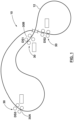
- one train system comprises a track 12 having parallel rails 12a, 12b.
- a train 14 includes a first or lead car 16 having both forward and rear wheel pairs 18, 20 operable on the track 12 for providing a free wheeling movement to the lead car.
- the train includes additional cars described as a second or rear car 22 and an intermediate car 24 or multiple intermediate cars carried between the lead and rear cars.
- the rear and intermediate cars 22, 24 include a forward pivotal connection 26 for pivotally connecting the intermediate and rear cars to adjacent forward cars.
- the rear and intermediate cars 22, 24 have only rear wheel pairs 20 operable on the track 12 for providing a free wheeling movement thereto.
- each of the cars has a side plate 28 affixed thereto.
- multiple drive stations 30 each have a variable frequency drive (VFD) including a drive tire 32 for frictionally contacting the side plate 28 and imparting a driven movement to each car and thus the train 14.
- VFD variable frequency drive
- the embodiment herein described includes each car having opposing side plates 28a, 28b and opposing drive tires 32a, 32b.
- each car may have a fixed side plate on each side, which runs the length of the car and spaced outside the wheels and tracks.
- These side plates may be located symmetrically with the wheels and parallel to the light rails. In another arrangement, the side plates may be located asymmetrical with the wheels.
- each drive stations 30 includes A/C inverters and a controller connected to every set of drive motors such that the motors may be synchronized through a modifying of at least one of voltage and frequency thereto.
- Forward or reverse motion of the train is the result of horizontal rotation of tires on opposite sides of the train turning in opposite directions with suitable pressure of said rotation that provides minimal slip between the tire surface and side plates. In other words, the two opposing tires are both pushed inward toward the center of the track.
- the drive tires 32 are further adapted to engage and apply pressure to the side plate 28 of the car.
- the lead car 16 has a trough 54, and opposing side plates 28a, 28b having a reduced distance between them for smooth entrance into opposing drive tires 32a, 32b of the drive station.
- the rear car 22 has a trough and opposing side plates 28a, 28b at a reduced distance between them to reduce shock when the train 14 exits the opposing drive tires 32a, 32b of the drive station 30.
- the intermediate cars 24 coupled to the lead car 16 and the rear car 22 by the clevis type coupling has its trough aligned to produce an overall open trough with gaps 56 between cars.
- a flexible flap 58 extends over the gap 56 between the cars 16, 24, 22.
- the cars each consist of a semicircle open trough and when joined or coupled together represents an open and continuous rigid trough for the entire length of the train.
- a flexible sealing flap attached near the front of the trailing car overlaps but is not attached to the rear of the lead car trough.
- a semi-circular trough is much better sealed with the flexible flap that other designs such as showed in U.S. Pat. No. 3,752,334 .
- This allows the train to follow the terrain and curves without losing its sealed integrity as a continuous trough.
- the material to be transported in the train is effectively supported and sealed by this flap as the material weight is equally distributed maintaining the seal against the metal trough of the forward car.
- the long continuous trough provides for simplified loading as the train can be loaded and unloaded while moving similar to a conveyor belt. This is a significant advantage over the batch loading equipment requirements of a conventional railroad hopper or rotary dump car.
- a system and method of controlling the rail transport system is provided, which is focused on the train (rather than the drive stations) and is optimized to determine the location of the train along the track to at least within one car length.
- drive stations 30 are spaced along the track 12 such that at least one drive station has contact with a train in order to maintain adequate control.
- a control center 48 may be remotely located from the drive stations 30 with each of the drive stations communicating with the control center for providing status information, such as train location, train speed, performance of the drive station itself, and the like. Communications from drive station to drive station and to the control center may employ hard wire, optical fiber, and/or radio wave transmissions as is desired for the conditions within which the system is to be operated.
- This system allows the use of multiple trains.
- a plurality of trains may be operated within a system comprising multiple drive stations 30 in communication with each other for driving both trains and maintaining a desirable spacing between the trains.
- alternate track and drive station configurations are anticipated including a reinversion location for reversing the direction of the train or trains traveling within the system.
- the control system uses the trains' location information to make small adjustments in train speed to assure the proper spacing of all trains on the course.
- acceleration rate incline grade and incline length will likely determine the peak horsepower required by the drive motors. Because the control system is capable of communicating drive speed information between drive stations for synchronization purposes, a train need not be fully accelerated before entering the next drive station. In addition, longer acceleration times allow the use of smaller horsepower (lower cost) drive motors.
- a method of controlling the rail transport system comprising a train 14 and drive stations 30 is provided and may be optimized to determine the location of the train 14 along the track 12, optionally, to at least within one car length.
- each of the drive stations 30 includes sensors, for example at least three sensors, spaced generally apart from one another so as to not interfere with each other.
- At least one of the cars, but ideally each of the cars, of the train 14 includes a corresponding car detection element (to be sensed by each of the sensors), such that when the train 14 passes through the drive station, each of the sensors may sense the corresponding car detection element of each car.
- the corresponding car detection element of the car may further be designed such that only one of the three sensors at the drive station 30 detects such car detection element at one time.
- each of the drive stations 30 includes three sensors spaced generally horizontally apart from one another at a select sufficient length so as to not interfere with each other (e.g., Sensor A, Sensor B, and Sensor C generally spaced at least about 45,72 cm (18 inches) apart).
- Each of the cars of the train 14 includes a corresponding car detection element (to be sensed by each of the sensors) having an effective area such that only one of the three sensors at the drive station 30 detects such car detection element at one time.
- the sensors may be a proximity, ultra-sonic, magnetic proximity or other comparable or suitable sensor.
- the proximity or ultra-sonic type sensors would each be used to detect a select surface area on each car, whereas the magnetic proximity sensor would be used to detect a magnet (e.g., a neodymium magnet) mounted on each car.
- the car detection element can be an integral part of the car, or mounted onto the car.
- the control system is adapted to determine the location of the train 14 along the track 12 to at least within one car length. Specifically, as each car of the train 14 passes through a drive station 30, each sensor sequentially detects the corresponding car detection element of a car and transmits an associated signal to the control system. In this way, presence or location of any one car of the train may be ascertained through this sensor arrangement at each of the drive stations.
- This sensor arrangement may also be used to determine direction of movement by the train. For example, when a train is moving through a drive station in a forward direction, a corresponding car detection element on each car triggers sensor A, then sensor B and then sensor C, to send associated signals in sequence to a control center. When the control center receives the associated signals in this sequence (e.g., sensed A, sensed B, sensed C), the control center assumes that one car has passed through the drive station upstream (or in a forward motion). When a train is moving through a drive station in a reverse direction, a corresponding car detection element on each car triggers sensor C, then sensor B and then sensor A, to send associated signals in sequence to the control center.
- a corresponding car detection element on each car triggers sensor A, then sensor B and then sensor A, to send associated signals in sequence to the control center.
- control center When the control center receives the associated signals in this reverse sequence (e.g., sensed C, sensed B, sensed A), the control center assumes that one car has passed through the drive station downstream (or in reverse). If the control center receives any other sequence than (sensed A, sensed B, sensed C) or (sensed C, sensed B, sensed A), stoppage of the train or a fault may be assumed.
- the control center receives the associated signals in this reverse sequence (e.g., sensed C, sensed B, sensed A)
- stoppage of the train or a fault may be assumed.
- the sensor arrangement may also be used to determine speed and acceleration of the train. For example, using (a) the distance between the corresponding car detection elements of two cars and (b) the length of time between the detection of sensors (e.g., (a) the distance between a magnet located on car 1 and a magnet located on car 2, and (b) the length of time between the detection of the magnet located on car 1 and the magnet of car 2 by sensor A), the speed of the train may be determined. Furthermore, sensor data over time or the sensing of multiple cars over time may be used to determine acceleration of the train.
- the sensor arrangement may generally be used to detect a stoppage of the train or a fault. Derailments can be caused by a number of factors, for example from debris on the track to the failure of a wheel bearing on the train.
- the sensor arrangement may be used to detect derailment of the train.
- the detection of a folded train is generally performed by comparing the number of cars between drive stations.
- the sensor arrangement may be used to sense the number of corresponding car detection elements on each car and, therefore, count cars that pass through a drive station. For example, if (a) drive stations D1 and D2 are 347,47 metres (1140 ft) apart and (b) each car is 20,42 metres (67 feet) in length each, there should be 17 cars between each drive station. If the difference of car count between each drive station is less than 17 cars or greater than 18 cars, then the control center assumes a possible derailment or a sensor failure. In turn, a signal can be sent to the drive station to stop the train.
- a control system which can mitigate damage from derailment by ensuring that the speed of each drive tire at an approaching drive station (e.g., D2) is maintained at the same speed as the train.
- an improved system and method is provided for controlling the movement of the train 14 along the track 12 based on the speed or acceleration detected at a preceding drive station.
- a first drive station 30 moves the train along the track 12 at a preselected speed or acceleration toward a second drive station (DS2).
- the cars of the train are sensed by the sensor arrangement described above, and the position of the train 14 relative to the first drive station (DS1) and the second drive station (DS2) are ascertained.
- a command signal is transmitted to the second drive station (DS2), which initiates the drive tire 32 at the second drive station (DS2).
- the second drive station (DS2) engages and maintains the train at about the same speed and/or acceleration as at the first drive station speed.
- the second drive station (DS2) is initiated and maintained at the speed and/or acceleration rate assigned to the train by the control center.
- select sensors at the second drive station (DS2) provide a determination that the second drive station (DS2) has engaged the train
- a stop command is transmitted to the first drive station for the drive tire 32 of the first drive station to stop. In this fashion, the train will pass control from one drive station to another. The transition from one drive station to another is synchronized.
- the distance between neighbouring drive stations is larger than the length of the train. Therefore, the train runs free for a certain distance between drive stations. Therefore, the train is essentially passed off between drive stations.
- the control system calculates the expected speed when the train reaches the second drive station based on the topography and track conditions (incline or decline of the track). The control system can then detect the location of the train, start the second drive station, and cause the second drive station to impart force from the drive tires to the train such that it maintains substantially the same speed as when it first reached the second drive station.
- the distance between the drive stations is shorter than the train and therefore the train is generally always in contact with a drive station.
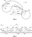
- a train system 110 includes a track 112 having one or more trains 114 riding thereon.
- the track 112 extends in a travel direction 116 and the trains 114 are driven in (forward) and counter to (reverse) the travel direction 116 by a plurality of drive stations 120.
- a plurality of position sensing units 122 each determines positions of the trains 114.
- a programmable logic controller (PLC) 124 is in signal communication with the drive stations 120 and position sensing units 122, and is configured to drive the train 114 with drive stations 120 based on the train positions determined by the position sensing units 122.
- PLC programmable logic controller
- the track 112 may include a pair of generally parallel rails 126, although other track 112 configurations may be employed.
- the track 112 can be arranged in a continuous loop or have discrete start and end points. Additionally, the track can have distinct branches, elevated sections, inverted sections, tunnels, etc. as needed or desired. It will be appreciated that the present invention may be employed with virtually any track configuration.
- the train 114 includes a plurality of cars 130 connected sequentially.
- a car length of each car in the travel direction 116 is optionally approximately equal.
- the cars 130 may roll in both right-side up and inverted positions on wheels 134 allowing for dumping of the contents of the car when in an inverted position.
- the cars 130 depicted include side plates 136 that are engaged by the drive stations 120 in order to impel the cars 130 in and against the travel direction 116, as will be explained in greater detail below. Although only three cars 130 are depicted for economy of illustration, trains composed of more or fewer cars may also be employed.
- Each car 130 carries a car detection element 140 to the presence and absence of which the position sensing units 122 are responsive.
- the car detection element 140 can be an integral part of the car, or mounted onto the car.
- the car detection element 140 is a metal member elongated in the travel direction 116 and attached to the bottom of each car 130.
- the length of the car detection element 140 in the travel direction is less than the car length.
- the car detection element 140 can be an approximately 2,5 cm ⁇ 5,1 cm ⁇ 121,9 cm (1 inch ⁇ 2 inch ⁇ 4 foot) metal tube mounted to the bottom of an approximately 2,44 metres (8 foot) long car.
- each drive station 120 includes a pair of drive wheels 142 mounted on opposite sides of the track 112. More or fewer drive wheels/pairs could be employed based on operational requirements, or another driving mechanism may be employed.
- the drive wheels 142 are laterally positioned in direction 144 so as to engage the side plates 136 on the on the cars 130. With the drive wheels 142 powered to spin in direction 146, the train 114 is thereby impelled forward in the travel direction 116. The train 114 can be impelled in reverse against the travel direction by turning the drive wheels 142 opposite direction 146.
- the drive wheels 142 can also be used to decelerate the train 114.
- the drive wheels 142 may be powered by one or more variable frequency (VFD) drives, as directed by the PLC 124.
- VFD variable frequency
- an exemplary one of the position sensing units 122 includes a plurality of position sensors 150, 152, 154 arranged one after the other in the travel direction 116.
- the other units 122 may be substantially identical, but only one is illustrated for the sake of brevity.
- the sensors 150, 152, 154 are commonly located on a sensor mount 156.
- the sensor mount 156 is arranged between the rails 126 of the track 112 such that the train 114 will pass thereover.
- the sensors 150, 152, 154 are positioned such that each car detection element 140 passes within their nominal range; for example, the car detection elements 140 will pass approximately 1,9 cm (0,750 inches) over the position sensors 150, 152, 154.
- the sensors 150, 152, 154 are proximity sensors, such as inductive proximity sensors, that are responsive to the presence and absence of the car detection elements 140 without making physical contact therewith.
- the sensors 150, 152, 154 may be highly unresponsive to nonmetallic objects, and to any objects outside of their nominal range. With no moving parts and largely immune to interference from dust and dirt, such sensors can function reliably with little or no maintenance in many harsh environments.
- the depicted embodiment includes first, second and third sensors 150, 152, 154.
- the first and second position sensors 150, 152 are separated in the travel direction 116, by a first sensor spacing 160.
- the third sensor 154 is separated from the second sensor 152 in the travel direction 116 by a second sensor spacing 162.
- the first and third sensors 150, 154 are separated in the travel direction 116 by a third sensor spacing 164, which is equal to the sum of the first and second sensor spacings 160, 162.
- advantageous approximate measurements for the first, second and third sensor spacings are about 0.61 metres (2 feet), 0.91 metres (3 feet) and 1.52 metres (5 feet), respectively.
- the PLC 124 is in signal communication with the drive units 120 and the position sensing units 122. Generally speaking, the PLC determines train position from the position sensing units 122 and controls the drive units 120 (for example, through one or more VFDs) based thereon.
- signal communication refers to communication effective to convey data. Various wired and/or wireless communications devices could be employed to effectuate signal communication between these components.
- train position refers broadly to the determination of the physical location of the train and/or derivatives thereof, such as train velocity and train acceleration/deceleration.
- the present invention is primarily focused on systems and methods for determining train position - the methods by which the PLC uses the determined train position to control trains can vary considerably within the scope of the present invention.
- the present invention in one embodiment, may be used in support of a control routine like that in U.S. Patent No. 8,140,202 , referenced above, where the PLC synchronizes drive wheel speeds between drive stations as a train passes from one drive station to the next.
- a "PLC” should generally be understood to be a computer device equipped to receive sensor inputs and generate control outputs, and programmable with one or more control routines governing the operational relationship between the inputs and outputs. While the PLC may be a purpose-built PLC, such as are marketed for that purpose, the present invention is not necessarily limited thereto.
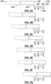
- Figures 9A-9G schematically illustrate positions of a leading (solid lines) and trailing (broken lines) train cars 130 with detection elements 140, as they pass over the first, second and third position sensors 150, 152, 154 (labeled A, B and C).
- Each of the position sensors has a high/on output, indicative of the presence of a detection element 140 and a low/off output, indicative of the absence of a detection element 140 (although these states could be reversed while preserving the overall functionality described herein).
- Figure 10 illustrates sensor response over time with the cars of Figure 9 passing thereover (a constant car velocity is used for this example). Sensor activations for the leading car are shown in solid lines, while switching to broken lines for activations by the trailing car. Labeled vertical lines 9A-9G in Figure 10 indicate sensor states at the car positions depicted in the corresponding Figures 9A-9G .
- Including the third sensor (C) further reduces the likelihood of a spurious recognition - an example of a car count would further include:
- a third sensor is of significant value where a plurality of connected cars are to be sensed.
- sensor A has transitioned to high for the trailing car, and it will be seen that this transition occurred after sensor B transitioned low but before sensor C did.
- the PLC can readily construe this as the beginning of the passage of the second car in the train, since there is sensor continuity (C to A) from the previous car.
- the present invention is not necessarily limited thereto.
- the position sensing unit 222 could be used alongside other position sensing components, such as those described in U.S. Patent No. 8,140,202 .
- other position sensing units 222 could be employed.
- a data tag reader is used to detect and read a plurality of data tags 240 on the plurality of cars 130.
- Each of the data tags 240 stores a unique identifier (such as a car serial number), which is read by the position sensing unit 222.
- the PLC 124 stores a list of the unique identifiers corresponding to the order of the cars 130. Optionally, this list is inputted when the corresponding train 114 is placed in service.
- the PLC By reading the identifiers, the PLC knows the position of every car in the train 114. This train position can be used to control the drive stations 120 substantially as described in connection with the foregoing embodiment. Additionally, if the position sensing unit 222 fails to read an identifier where and when expected, possibly corresponding to a missing or damaged data tag 240, the PLC 124 can be configured to bring the train 114 to a controlled stop until the problem is resolved. Also, the identifiers can indentify not only individual cars but classes or types of car. Thus, the PLC 124 can also intervene if identifiers corresponding to improper cars are detected in the system 110.
- RFID tags are passive, and are thus powered by the signal received from the sensing unit 222 and transmit their identifier in response.
- a separate power source for the tags 240 is not necessary and they can remain in place for an extended period without battery replacement or other maintenance.
- active RFID tags could alternately be employed.
Description
- The present invention generally relates to determining train position, and more particularly, to determining train position in automated train systems with no internal drive for conveying bulk materials.
- Methods and arrangements for moving bulk materials in conventional trains, trucks, conveyor belts, aerial tramways or as a slurry in a pipeline are well known and are typically used in various industries because of site-specific needs or experience. In the minerals and aggregate industries, for example, bulk materials are moved from mining or extraction sites to a process facility for upgrading or sizing. Trucks had been the system of choice for many years for moving bulk materials. Trucks were enlarged for off-road vehicles because of their efficient transport of bulk materials and increased capacity. These vehicles, however, are limited to site specific applications and are provided at a high capital cost. Major off-road trucks have evolved that require very wide roadways for passing each other, are not energy efficient per ton-mile of material transported, have limited hill climbing ability, and are dangerous because of potential of operator error as well as being environmentally unpleasant neighbors.
- Trains have been used for many years for bulk material transport in hopper cars. Because of low friction, due to free rolling iron or steel wheels on steel tracks trains are very efficient users of energy but are limited in capacity relative to the drivers or locomotives required. Large tonnage long trains use multiple drivers that are heavy units, which dictate the weight of rail and ballast requirements. All railroads must be designed for the weight of the drivers or locomotives including fuel, not the combination of car plus loads, which are significantly less. The drivers need to be of sufficient weight so that the rotary drive tire makes contact with the stationary rail and must have sufficient friction to produce forward or reverse movement of what will include heavily loaded cars. The level of inclination that conventional railroad systems are capable of traversing is limited to the friction between the weighted drive wheels and track. Rail cars are individual units that each has to be loaded in a batch process, one car at a time. Bulk materials can be unloaded from hopper cars by opening bottom dump hatches or can be individually rotated to dump out of the top. Spotting cars for both loading and unloading is time consuming and labor intensive.
- Although moving from one location to another may be cost effective, the added cost of batch loading and unloading stages in shorter distance transports reduces the rail transport cost effectiveness. With normal single dual track train systems only one train can be used on a system at a time.
- Conveyor belts have been used for many years to move bulk materials. A wide variety of conveyor belt systems exist that can move practically every conceivable bulk material. Very long distance single belt runs are very capital cost intensive and are subject to catastrophic failure when a belt tears or rips, typically shutting down the entire system and dumping the carried load, requiring cleanup. Conveyor belts are relatively energy efficient but can require high maintenance because of an inherent problem of multiple idler bearings requiring constant checking and replacement. Short distance conveyor belts are commonly used in dry or clamp transport of almost all types of materials. Because conveyor belts are very flexible and desirably operated over fairly flat terrain, they are not efficient at transporting moderately high solids slurry where water and fine particles can accumulate in low spots and spill over the side creating wet spilled slurry handling problems.
- Some bulk materials can be transported in pipelines when mixed with water to form a slurry that is pushed or pulled with a motor driven pump impeller in an airless or flooded environment. The size of the individual particles that are present in the bulk materials dictates the transport speed necessary to maintain movement. For example, if large particles are present then the velocity must be high enough to maintain movement by saltation or skidding along the bottom of the pipe of the very largest particles. Because pipelines operate in a dynamic environment, friction is created with the stationary pipe wall by a moving fluid and solid mass. The higher the speed of the moving mass the higher the friction loss at the wall surface requiring increased energy to compensate. Depending on the application, the bulk material has to be diluted with water initially to facilitate transport and dewatering at the discharge end.
- Light rail, narrow gage railroads for transporting bulk material from mines and the like is known as described by way of example with reference to
U.S. Pat. No. 3,332,535 to Hubert et al . wherein a light rail train made up of several cars is propelled by drive wheels and electric motors combinations, dumping over an outside loop. By way of further example,U.S. Pat. No. 3,752,334 to Robinson, Jr. et al . discloses a similar narrow gage railroad wherein the cars are driven by an electric motor and drive wheels.U.S. Pat. No. 3,039,402 to Richardson describes a method of moving railroad cars using a stationary friction drive tire. - While the above described transport systems and methods have specific advantages over conventional systems, each is highly dependent upon a specific application. It has become apparent that increases in labor, energy and material costs as well as environmental concerns, that alternate transport methods need to be applied that are energy and labor efficient, quiet, non-polluting, and esthetically unobtrusive. US Patent Publications
US 2003/0226470 to Dibble et al . for "Rail Transport System for Bulk Materials",US 2006/0162608 to Dibble for "Light Rail Transport System for Bulk Materials", andU.S. Pat. No. 8,140,202 to Dibble describe a light rail train utilizing an open semi-circular trough train with drive stations. Such a light rail system offers an innovative alternative to the above mentioned material transport systems and provides for the transport of bulk materials using a plurality of connected cars open at each end except for the first and last cars, which have end plates. The train forms a long open trough and has a flexible flap attached to each car and overlapping the car in front to prevent spillage during movement. The lead car has four wheels and tapered side drive plates in the front of the car to facilitate entry into the drive stations. The cars that follow have two wheels with a clevis hitch connecting the front to the rear of the car immediately forward. Movement of the train is provided by a series of appropriately placed drive stations having drive motors on either side of the track which are AC electric motors with drive means such as tires to provide frictional contact with the side drive plates. At each drive station, each drive motor is connected to an AC inverter and controller for drive control, with both voltage and frequency being modified as needed. The electric motors each turn a tire in a horizontal plane that physically contacts two parallel side drive plates external of the wheels of each car. Pressure on the side drive plates by these drive tires converts the rotary motion of the tires into horizontal thrust. The wheels on the cars are spaced to allow operation in an inverted position by use of a double set of rails to allow the cars to hang upside down for unloading. By rotating this double track system the unit train can be returned to it normal operating condition. Such a system is well known and commercially referred to as the Rail-Veyor™ material handling system. - Flanged wheels may be symmetrical to the side drive plates allowing operation in an inverted position which, when four rails are used to encapsulate the wheel outside loop discharge of the bulk material is possible. By using elevated rails, the train can operate in the inverted position as easily as in the conventional manner.
- Yet further, drives for such light rail systems have been developed as described in
U.S. Pat. No. 5,067,413 to Kiuchi et al. describing a device for conveying travelable bodies which are provided no driving source, on a fixed path. A plurality of travelable bodies travels on the fixed path while aligned substantially in close contact with each other. Traveling power is transmitted to one of a plurality of travelable bodies which is positioned on at least one end of the alignment. The traveling power drives the travelable body with frictional force while pressing one side surface of the travelable body, and is transmitted to the travelable body while backing up the other side surface of the travelable body. A device to transmit traveling power is arranged on only a part of the fixed path. - It is known to sense a train's position by using an arrangement of proximity sensors located so as to sense both a train's side plate and each wheel of the train as it approaches and passes a drive station, as disclosed in
U.S. Patent No. 8,140,202 for "Method of Controlling a Rail Transport System for Conveying Bulk Materials". - Although the train position determination systems and methods employed therein have been found effective, a need exists for a further optimized or improved system.
- In at least some embodiments, the present invention provides for systems and methods for sensing a train position of a train with no internal drive operating in an automated train system. According to one embodiment of the present invention that is not recited in the claims, a train system comprises a track extending in a travel direction, a plurality of cars riding on the track and connected to form a train, a position sensing unit, and a programmable logic controller (PLC) in signal communication with the position sensing unit and configured to determine a train position based on inputs therefrom.
- In one embodiment of a position sensing unit that is not recited in the claims, each of the plurality of cars has a substantially identical car length in the travel direction and there are a plurality of car detection elements on the plurality of cars. Each of the plurality of car detection elements has a substantially identical detection element length in the travel direction, the detection element length being less than the car length.
- The position sensing unit may include a first position sensor arranged along the track responsive to the presence and/or absence of each of the plurality of car detection elements and a second position sensor arranged along the track responsive to the presence and/or absence of each of the plurality of car detection elements and separated from the first position sensor in the travel direction by a first sensor spacing, the first sensor spacing being less than the detection element length.
- According to one embodiment of alternate position sensing unit that is not recited in the claims, the cars are connected in a car order and a plurality of data tags are arranged on the plurality of cars, each of the plurality of data tags storing a unique identifier. The position sensing unit includes a data tag reader arranged along the track and operable to detect each of the plurality of data tags in sequence and read the unique identifiers therefrom. The programmable logic controller stores a list of the unique identifiers corresponding to the car order and is configured to determine a train position based on inputs from the position sensing unit and the stored list.
- In one embodiment, the present invention provides for a rail transport system for conveying bulk materials, including:
- a plurality of cars adapted to form at least two separate trains, at least one car having a pair of side drive plates and is adapted for carrying the bulk materials, and a car detection element associated to at least one of the cars,
- a drive station for frictionally contacting the side drive plates of at least one of the cars for imparting a driven movement to each contacted car, and
- a control system according to any one of
claims 1 to 4. - In a further embodiment of the rail transport system or systems outlined above, the drive station includes a drive unit and a drive tire arrangement for frictionally contacting the side drive plates of at least one of the cars, and wherein the drive unit is adapted to control the drive tire arrangement in response to the determined status of one of the cars.
- In a further embodiment of the rail transport system or systems outlined above, the drive unit is adapted to control the drive tire arrangement to increase driven movement from the drive tire arrangement to a car engaged thereto in response to the determined status information.
- In a further embodiment of the rail transport system or systems outlined above, the drive unit is adapted to control the drive tire arrangement to decrease driven movement from the drive tire arrangement to a car engaged thereto in response to the determined status information.
- In a further embodiment of the rail transport system or systems outlined above, the car detection element has an effective area such that only one of the sensors detects the car detection element at one time.
- In a further embodiment of the rail transport system or systems outlined above, as each car passes near the drive station, each sensor sequentially detects the car detection element of the car.
- In a further embodiment of the rail transport system or systems outlined above, the car detection element is a metal member elongated in a travel direction of the car.
- In another embodiment, the present invention provides for a control system for a rail transport system for conveying bulk materials, wherein the rail transport system includes a plurality of cars adapted to form at least two separate trains, and wherein at least one car of each train has a pair of side drive plates and is adapted for carrying the bulk materials, the rail transport system further including at least one drive station for frictionally contacting the side drive plates for imparting a driven movement to each train, the control system comprising:
- a multiple sensor arrangement comprising at least three sensors with a known pre-determined spacing between each sensor permitting sequential detection of a car detection element of at least one car of each of the trains as the car passes by, wherein the pre-determined spacing between a first sensor and a second sensor of the multiple sensor arrangement is less than the pre-determined spacing between the second sensor and a third sensor of the multiple sensor arrangement, for sensing a car detection element of at least one car of each of the trains,
- wherein the multiple sensor arrangement is adapted to determine status information associated with the at least one car wherein the status information is at least one of the speed of the car, speed of the train associated with the car, acceleration rate of the car, acceleration rate of the train associated with the car, direction of movement of the car, derailment of the car, location of the car, locations of the train, or derailment of the train associated with the car.
- The sensor arrangement may be operatively coupled to the drive station.
- As a car passes near the drive station, the sensor arrangement may detect the corresponding car detection element of the car.
- The sensor arrangement may be located separate and apart from the drive station.
- In a further embodiment of the control system or systems outlined above, the sensors are a proximity sensor, a magnetic proximity sensor, or an ultra-sonic sensor.
- In a further embodiment of the control system or systems outlined above, the multiple sensor arrangement is a three sensor arrangement.
- In a further embodiment of the control system or systems outlined above, the three sensor arrangement can be implemented to sequentially detect the car detection element of at least one car.
- In yet another embodiment that is not recited in the claims, the present invention provides for a method for controlling a rail transport system for conveying bulk materials, wherein the rail transport system includes a train having a pair of side drive plates and is adapted for carrying the bulk materials, wherein the rail transport system further includes at least two drive stations for frictionally contacting the side drive plates for imparting a driven movement to the train, the method comprising:
- imparting a driven movement to the train at a select speed and acceleration at the first drive station,
- determining the position of the train relative to the second drive station, and
- when the train is determined to be at a select position relative to the second drive station, initiating the second drive station such that driven movement is imparted to the train at the second drive station to maintain substantially the same speed of the train as when the train was at the first drive station.
- In a further embodiment of the method or methods outlined above that is not recited in the claims, the method(s) further include the step of
stopping operation of the second drive station if the second drive station is not at a condition for imparting to the train driven movement to maintain substantially the same speed of the train as when the train was at the first drive station. - In a further embodiment of the method or methods outlined above that is not recited in the claims, the at least two drive stations are positioned apart a greater distance than the length of the train.
- In yet another embodiment that is not recited in the claims, the present invention provides for a method for controlling a rail transport system for conveying bulk materials, wherein the rail transport system includes a train having a pair of side drive plates and is adapted for carrying the bulk materials, wherein the rail transport system further includes a drive station for frictionally contacting the side drive plates for imparting a driven movement to the train, the method comprising:
- determining the position of the train relative to the drive station, and
- when the train is determined to be at a select position relative to the drive station, initiating the drive station to impart driven movement to the train at a desired speed when the train passes therethrough.
- In a further embodiment of the method or methods outlined above that is not recited in the claims, the rail transport system further includes a second drive station for frictionally contacting the side drive plates for imparting a driven movement to the train, and wherein the method further comprises:
ensuring that at least one of the cars of the train is in contact with one of the drive stations at all times. - In a further embodiment of the method or methods outlined above that is not recited in the claims, the rail transport system further includes a second drive station for frictionally contacting the side drive plates for imparting a driven movement to the train, and wherein the distance between two drive stations is longer than a length of the train. In a further embodiment of the system or systems outlined above that is not recited in the claims, the system further comprises a plurality of cars adapted to form a second train, each car having a pair of side drive plates and is adapted for carrying the bulk materials.
- In yet another embodiment that is not recited in the claims, the present invention provides for a train system comprising:
- a track extending in a travel direction;
- a plurality of cars situated on the track and connected to form a train;
- a plurality of car detection elements on the plurality of cars, each of the plurality of car detection elements having a substantially identical detection element length in the travel direction, the detection element length being less than the car length;
- a position sensing unit including:
- a first position sensor arranged along the track responsive to the presence and absence of each of the plurality of car detection elements;
- a second position sensor arranged along the track responsive to the presence and absence of each of the plurality of car detection elements and separated from the first position sensor in the travel direction by a first sensor spacing, the first sensor spacing being less than the detection element length; and
- a programmable logic controller (PLC) in signal communication with the position sensing unit and configured to determine a train position based on inputs therefrom.
- In a further embodiment of the system or systems outlined above that is not recited in the claims, the position sensing unit further includes a third position sensor arranged along the track responsive to the presence and absence of each of the plurality of car detection elements, separated by the second position sensor in the travel distance by a second sensor spacing and separated from the first position sensor by a third sensor spacing equal to the sum of the first and second sensor spacings, the second sensor spacing being less than the detection element length.
- In a further embodiment of the system or systems outlined above that is not recited in the claims, the third sensor spacing is greater than the detection element length.
- In a further embodiment of the system or systems outlined above that is not recited in the claims, the first and second sensor spacings are unequal.
- In a further embodiment of the system or systems outlined above that is not currently recited in the claims, the third sensor spacing is less than the car length.
- In a further embodiment of the system or systems outlined above that is not recited in the claims, the track includes a pair of parallel rails and the position sensing unit is arranged between the rails such that the train passes thereover.
- In a further embodiment of the system or systems outlined above that is not currently recited in the claims, the position sensing unit includes a sensor mount elongated in the travel direction and the position sensors are mounted thereto.
- In a further embodiment of the system or systems outlined above that is not recited in the claims, each of the plurality of car detection elements is a metal member extending under a respective one of the plurality of cars; and
wherein each of the position sensors is a proximity detector responsive to the presence and absence of each metal member. - In a further embodiment of the system or systems outlined above that is not recited in the claims, the system(s) further comprises a drive station arranged along the track and operable by the PLC to impart motion to the train.
- In a further embodiment of the system or systems outlined above that is not recited in the claims, the drive station includes a pair of drive wheels on opposite sides of the track, the drive wheels engaging each of the plurality of cars when passing therebetween.
- In a further embodiment of the system or systems outlined above that is not recited in the claims, the position sensing unit is located at the drive station.
- In a further embodiment of the system or systems outlined above that is not recited in the claims, the system(s) further comprises:
- a plurality of additional drive stations arranged along the track at intervals and operable by the PLC to impart motion to the train; and
- a plurality of additional position sensing units identical to the position sensing unit, each of the plurality of additional position sensing units being located a respective one of the plurality of additional drive stations.
- In a further embodiment of the system or systems outlined above that is not recited in the claims, the PLC is configured to sequentially operate the drive stations based on the input from the position sensing units.
- In a further embodiment of the system or systems outlined above that is not recited in the claims, each of the plurality of cars has a substantially identical car length in the travel direction.
- In yet another embodiment that is not recited in the claims, the present invention provides for a train system comprising:
- a track extending in a travel direction;
- a plurality of cars situated on the track and connected in a car order to form a train;
- a plurality of data tags on the plurality of cars, each of the plurality of data tags storing a unique identifier;
- a position sensing unit including:
a data tag reader arranged along the track and operable to detect each of the plurality of data tags in sequence and read the unique identifiers therefrom; and - a programmable logic controller in signal communication with the position sensing unit, the programmable logic controller storing a list of the unique identifiers corresponding to the car order and being configured to determine a train position based on inputs from the position sensing unit and the stored list.
- In a further embodiment of the system or systems outlined above that is not recited in the claims, the plurality of data tags are radio frequency identification (RFID) tags and the data tag reader is a RFID tag reader.
- In a further embodiment of the system or systems outlined above that is not by the claimed invention, the RFID tags are passive RFID tags.
- In a further embodiment of the system or systems outlined above that is not recited in the claims, the plurality of data tags are not located on outer surfaces of the plurality of cars.
- In a further embodiment of the system or systems outlined above that is not recited in the claims, the system(s) further comprises a drive station arranged along the track and operable by the PLC to impart motion to the train.
- In a further embodiment of the system or systems outlined above that is not recited in the claims, the PLC is configured to bring the train to a controlled stop if one of the unique identifiers is not read at its place in the car order.
- In a further embodiment of the system or systems outlined above that is not recited in the claims, the position sensing unit is located at the drive station.
- In a further embodiment of the system or systems outlined above that is not recited in the claims, the system(s) further comprises:
- a plurality of additional drive stations arranged along the track at intervals and operable by the PLC to impart motion to the train; and
- a plurality of additional position sensing units identical to the position sensing unit, each of the plurality of additional position sensing units being located a respective one of the plurality of additional drive stations.
- In a further embodiment of the system or systems outlined above that is not recited in the claims, the PLC is configured to sequentially operate the drive stations based on the input from the position sensing units.
- In a further embodiment of the system or systems outlined above that is not recited in the claims, the intervals are greater than the length of the train PLC calculates the expected speed of the train when reaching a subsequent drive station based on the location of the train, the topography and track conditions and starts the subsequent drive station to cause the subsequent drive station to impart force to the train such that it maintains substantially the same speed as when it first reached the subsequent drive station.
- Various embodiments of the invention are described by way of example with reference to the accompanying drawings and appendices. The present invention will be apparent to those skilled in the art by reading the following detailed description of various embodiments thereof, with reference to the attached drawings, in which:
-
Figure 1 is a diagrammatical illustration of one rail system in keeping with the teachings of the present invention; -
Figures 2 and 3 are side and top plan views, respectively, of one embodiment of a train operable with the system ofFigure 1 ; -
Figure 4 is a diagrammatical illustration of a track arrangement operable with a control system of the present invention; -
Figure 5 is a schematic overview of a train system with position sensing units, according to a further embodiment of the present invention; -
Figure 6 is a side view of a portion of the train system ofFigure 5 , with a train thereon shown in partial cutaway to reveal hidden components; -
Figure 7 is a top view of a portion of the train system ofFigure 5 , including a drive station with the train ofFigure 6 passing therethrough, with hidden components shown in broken lines; -
Figure 8 is a top view of the drive station ofFigure 7 , with components removed and the train absent, showing an exemplary position sensing unit ofFigure 5 ; -
Figure 9 is a series of schematic side views of a train passing over one of the sensing units ofFigure 5 ; -
Figure 10 is a state diagram of states of the position sensing unit ofFigure 9 as the train passes thereover; and -
Figure 11 is a top view of a portion of the train system ofFigure 5 , including a drive station with the train ofFigure 6 passing therethrough past an alternate position sensing unit embodiment, with hidden components shown in broken lines. - The present invention will now be described more fully hereinafter with reference to the accompanying drawings and appendices, in which illustrative embodiments of the invention are shown. This invention may, however, be embodied in many different forms and should not be construed as limited to the embodiments and examples set forth herein nor should the invention be limited to the dimensions set forth herein. Rather, the embodiments herein presented are provided so that this disclosure will be thorough and complete, and will fully convey the scope of the invention to those skilled in the art by way of these illustrative and non-limiting embodiments and examples. It will be understood to the person of skill in the art that many different forms and variations of the embodiments, examples and illustrations provided herein may be possible, and the various embodiments, examples, and illustrations provided herein should be construed as non-limiting embodiments, examples, and illustrations.
- With reference initially to
Figures 1-3 , onetrain system 10, in keeping with the teachings of the present invention, comprises atrack 12 havingparallel rails train 14 includes a first orlead car 16 having both forward and rear wheel pairs 18, 20 operable on thetrack 12 for providing a free wheeling movement to the lead car. For the embodiment herein described by way of example, the train includes additional cars described as a second orrear car 22 and anintermediate car 24 or multiple intermediate cars carried between the lead and rear cars. The rear andintermediate cars pivotal connection 26 for pivotally connecting the intermediate and rear cars to adjacent forward cars. The rear andintermediate cars track 12 for providing a free wheeling movement thereto. - With continued reference to
Figure 2 , each of the cars has aside plate 28 affixed thereto. With reference toFigures 1 ,3-4 ,multiple drive stations 30 each have a variable frequency drive (VFD) including adrive tire 32 for frictionally contacting theside plate 28 and imparting a driven movement to each car and thus thetrain 14. As illustrated with continued reference toFigure 3 , the embodiment herein described includes each car having opposingside plates drive tires drive stations 30 includes A/C inverters and a controller connected to every set of drive motors such that the motors may be synchronized through a modifying of at least one of voltage and frequency thereto. Forward or reverse motion of the train is the result of horizontal rotation of tires on opposite sides of the train turning in opposite directions with suitable pressure of said rotation that provides minimal slip between the tire surface and side plates. In other words, the two opposing tires are both pushed inward toward the center of the track. In order the stop the train, thedrive tires 32 are further adapted to engage and apply pressure to theside plate 28 of the car. - As herein illustrated, the
lead car 16 has atrough 54, and opposingside plates drive tires rear car 22 has a trough andopposing side plates train 14 exits the opposingdrive tires drive station 30. Theintermediate cars 24 coupled to thelead car 16 and therear car 22 by the clevis type coupling has its trough aligned to produce an overall open trough withgaps 56 between cars. Aflexible flap 58 extends over thegap 56 between thecars U.S. Pat. No. 3,752,334 . This allows the train to follow the terrain and curves without losing its sealed integrity as a continuous trough. The material to be transported in the train is effectively supported and sealed by this flap as the material weight is equally distributed maintaining the seal against the metal trough of the forward car. The long continuous trough provides for simplified loading as the train can be loaded and unloaded while moving similar to a conveyor belt. This is a significant advantage over the batch loading equipment requirements of a conventional railroad hopper or rotary dump car. - As set forth herein and with reference to
Figure 4 , a system and method of controlling the rail transport system is provided, which is focused on the train (rather than the drive stations) and is optimized to determine the location of the train along the track to at least within one car length. Referring back toFigures 1-4 , drivestations 30 are spaced along thetrack 12 such that at least one drive station has contact with a train in order to maintain adequate control. Acontrol center 48 may be remotely located from thedrive stations 30 with each of the drive stations communicating with the control center for providing status information, such as train location, train speed, performance of the drive station itself, and the like. Communications from drive station to drive station and to the control center may employ hard wire, optical fiber, and/or radio wave transmissions as is desired for the conditions within which the system is to be operated. This system allows the use of multiple trains. For example, a plurality of trains may be operated within a system comprisingmultiple drive stations 30 in communication with each other for driving both trains and maintaining a desirable spacing between the trains. As will come to the mind of those skilled in the art, now having the benefit of the teachings of the present invention, alternate track and drive station configurations are anticipated including a reinversion location for reversing the direction of the train or trains traveling within the system. - With regard to operation of the drive control system, only the drive in contact with the train will preferably be running at any given point in time. The control system uses the trains' location information to make small adjustments in train speed to assure the proper spacing of all trains on the course. With regard to acceleration rate, incline grade and incline length will likely determine the peak horsepower required by the drive motors. Because the control system is capable of communicating drive speed information between drive stations for synchronization purposes, a train need not be fully accelerated before entering the next drive station. In addition, longer acceleration times allow the use of smaller horsepower (lower cost) drive motors.
- With continued reference to
Figure 4 , a method of controlling the rail transport system comprising atrain 14 and drivestations 30 is provided and may be optimized to determine the location of thetrain 14 along thetrack 12, optionally, to at least within one car length. Specifically, each of thedrive stations 30 includes sensors, for example at least three sensors, spaced generally apart from one another so as to not interfere with each other. At least one of the cars, but ideally each of the cars, of thetrain 14 includes a corresponding car detection element (to be sensed by each of the sensors), such that when thetrain 14 passes through the drive station, each of the sensors may sense the corresponding car detection element of each car. The corresponding car detection element of the car may further be designed such that only one of the three sensors at thedrive station 30 detects such car detection element at one time. - In one example, each of the
drive stations 30 includes three sensors spaced generally horizontally apart from one another at a select sufficient length so as to not interfere with each other (e.g., Sensor A, Sensor B, and Sensor C generally spaced at least about 45,72 cm (18 inches) apart). Each of the cars of thetrain 14 includes a corresponding car detection element (to be sensed by each of the sensors) having an effective area such that only one of the three sensors at thedrive station 30 detects such car detection element at one time. The sensors may be a proximity, ultra-sonic, magnetic proximity or other comparable or suitable sensor. In this example, the proximity or ultra-sonic type sensors would each be used to detect a select surface area on each car, whereas the magnetic proximity sensor would be used to detect a magnet (e.g., a neodymium magnet) mounted on each car. The car detection element can be an integral part of the car, or mounted onto the car. - Using the three sensors, the control system is adapted to determine the location of the
train 14 along thetrack 12 to at least within one car length. Specifically, as each car of thetrain 14 passes through adrive station 30, each sensor sequentially detects the corresponding car detection element of a car and transmits an associated signal to the control system. In this way, presence or location of any one car of the train may be ascertained through this sensor arrangement at each of the drive stations. - This sensor arrangement may also be used to determine direction of movement by the train. For example, when a train is moving through a drive station in a forward direction, a corresponding car detection element on each car triggers sensor A, then sensor B and then sensor C, to send associated signals in sequence to a control center. When the control center receives the associated signals in this sequence (e.g., sensed A, sensed B, sensed C), the control center assumes that one car has passed through the drive station upstream (or in a forward motion). When a train is moving through a drive station in a reverse direction, a corresponding car detection element on each car triggers sensor C, then sensor B and then sensor A, to send associated signals in sequence to the control center. When the control center receives the associated signals in this reverse sequence (e.g., sensed C, sensed B, sensed A), the control center assumes that one car has passed through the drive station downstream (or in reverse). If the control center receives any other sequence than (sensed A, sensed B, sensed C) or (sensed C, sensed B, sensed A), stoppage of the train or a fault may be assumed.
- The sensor arrangement may also be used to determine speed and acceleration of the train. For example, using (a) the distance between the corresponding car detection elements of two cars and (b) the length of time between the detection of sensors (e.g., (a) the distance between a magnet located on
car 1 and a magnet located oncar 2, and (b) the length of time between the detection of the magnet located oncar 1 and the magnet ofcar 2 by sensor A), the speed of the train may be determined. Furthermore, sensor data over time or the sensing of multiple cars over time may be used to determine acceleration of the train. - As discussed above, the sensor arrangement may generally be used to detect a stoppage of the train or a fault. Derailments can be caused by a number of factors, for example from debris on the track to the failure of a wheel bearing on the train. In one specific example, the sensor arrangement may be used to detect derailment of the train. The detection of a folded train is generally performed by comparing the number of cars between drive stations. Specifically, the sensor arrangement may be used to sense the number of corresponding car detection elements on each car and, therefore, count cars that pass through a drive station. For example, if (a) drive stations D1 and D2 are 347,47 metres (1140 ft) apart and (b) each car is 20,42 metres (67 feet) in length each, there should be 17 cars between each drive station. If the difference of car count between each drive station is less than 17 cars or greater than 18 cars, then the control center assumes a possible derailment or a sensor failure. In turn, a signal can be sent to the drive station to stop the train.
- In yet another embodiment, a control system is provided which can mitigate damage from derailment by ensuring that the speed of each drive tire at an approaching drive station (e.g., D2) is maintained at the same speed as the train. Specifically, an improved system and method is provided for controlling the movement of the
train 14 along thetrack 12 based on the speed or acceleration detected at a preceding drive station. In one example, a first drive station 30 (DS1) moves the train along thetrack 12 at a preselected speed or acceleration toward a second drive station (DS2). The cars of the train are sensed by the sensor arrangement described above, and the position of thetrain 14 relative to the first drive station (DS1) and the second drive station (DS2) are ascertained. When thetrain 14 is determined to be within a certain distance from the second drive station (DS2), a command signal is transmitted to the second drive station (DS2), which initiates thedrive tire 32 at the second drive station (DS2). In order to reduce wear of the drive tire and cars, the second drive station (DS2) engages and maintains the train at about the same speed and/or acceleration as at the first drive station speed. In other words, the second drive station (DS2) is initiated and maintained at the speed and/or acceleration rate assigned to the train by the control center. When select sensors at the second drive station (DS2) provide a determination that the second drive station (DS2) has engaged the train, a stop command is transmitted to the first drive station for thedrive tire 32 of the first drive station to stop. In this fashion, the train will pass control from one drive station to another. The transition from one drive station to another is synchronized. - In various embodiments, the distance between neighbouring drive stations is larger than the length of the train. Therefore, the train runs free for a certain distance between drive stations. Therefore, the train is essentially passed off between drive stations. In this arrangement, the control system calculates the expected speed when the train reaches the second drive station based on the topography and track conditions (incline or decline of the track). The control system can then detect the location of the train, start the second drive station, and cause the second drive station to impart force from the drive tires to the train such that it maintains substantially the same speed as when it first reached the second drive station.
- In various other embodiments, the distance between the drive stations is shorter than the train and therefore the train is generally always in contact with a drive station.
- Many modifications and other embodiments of the inventions set forth herein will come to mind to one skilled in the art to which these inventions pertain having the benefit of the teachings presented in the foregoing descriptions and the associated drawings.
- Therefore, it is to be understood that the inventions are not to be limited to the specific examples of the embodiments disclosed and that modifications and other embodiments are intended to be included within the scope of the appended claims. Although specific terms are employed herein, they are used in a generic and descriptive sense only and not for purposes of limitation.
- Referring to
Figures 5 and 6 , according to a further embodiment of the present invention atrain system 110 includes atrack 112 having one ormore trains 114 riding thereon. Thetrack 112 extends in atravel direction 116 and thetrains 114 are driven in (forward) and counter to (reverse) thetravel direction 116 by a plurality ofdrive stations 120. A plurality ofposition sensing units 122 each determines positions of thetrains 114. A programmable logic controller (PLC) 124 is in signal communication with thedrive stations 120 andposition sensing units 122, and is configured to drive thetrain 114 withdrive stations 120 based on the train positions determined by theposition sensing units 122. - Referring also to
Figure 7 , thetrack 112 may include a pair of generallyparallel rails 126, althoughother track 112 configurations may be employed. Thetrack 112 can be arranged in a continuous loop or have discrete start and end points. Additionally, the track can have distinct branches, elevated sections, inverted sections, tunnels, etc. as needed or desired. It will be appreciated that the present invention may be employed with virtually any track configuration. - Referring to
Figures 6 and7 , thetrain 114 includes a plurality ofcars 130 connected sequentially. A car length of each car in thetravel direction 116 is optionally approximately equal. Additionally, thecars 130 may roll in both right-side up and inverted positions onwheels 134 allowing for dumping of the contents of the car when in an inverted position. Thecars 130 depicted includeside plates 136 that are engaged by thedrive stations 120 in order to impel thecars 130 in and against thetravel direction 116, as will be explained in greater detail below. Although only threecars 130 are depicted for economy of illustration, trains composed of more or fewer cars may also be employed. - Each
car 130 carries acar detection element 140 to the presence and absence of which theposition sensing units 122 are responsive. As outlined above, thecar detection element 140 can be an integral part of the car, or mounted onto the car. In the depicted embodiment, thecar detection element 140 is a metal member elongated in thetravel direction 116 and attached to the bottom of eachcar 130. In one embodiment, the length of thecar detection element 140 in the travel direction is less than the car length. For example, thecar detection element 140 can be an approximately 2,5 cm × 5,1 cm × 121,9 cm (1 inch × 2 inch × 4 foot) metal tube mounted to the bottom of an approximately 2,44 metres (8 foot) long car. - Referring to
Figure 7 , in the depicted embodiment, eachdrive station 120 includes a pair ofdrive wheels 142 mounted on opposite sides of thetrack 112. More or fewer drive wheels/pairs could be employed based on operational requirements, or another driving mechanism may be employed. Thedrive wheels 142 are laterally positioned indirection 144 so as to engage theside plates 136 on the on thecars 130. With thedrive wheels 142 powered to spin indirection 146, thetrain 114 is thereby impelled forward in thetravel direction 116. Thetrain 114 can be impelled in reverse against the travel direction by turning thedrive wheels 142opposite direction 146. Thedrive wheels 142 can also be used to decelerate thetrain 114. Thedrive wheels 142 may be powered by one or more variable frequency (VFD) drives, as directed by thePLC 124. - Referring to
Figure 8 , an exemplary one of theposition sensing units 122 includes a plurality ofposition sensors travel direction 116. Theother units 122 may be substantially identical, but only one is illustrated for the sake of brevity. For ease of installation and replacement, thesensors sensor mount 156. Thesensor mount 156 is arranged between therails 126 of thetrack 112 such that thetrain 114 will pass thereover. In this arrangement, thesensors car detection element 140 passes within their nominal range; for example, thecar detection elements 140 will pass approximately 1,9 cm (0,750 inches) over theposition sensors - In the depicted embodiment, the
sensors car detection elements 140 without making physical contact therewith. Thesensors - In various embodiments, there are at least two position sensors, and the depicted embodiment includes first, second and
third sensors second position sensors travel direction 116, by afirst sensor spacing 160. Thethird sensor 154 is separated from thesecond sensor 152 in thetravel direction 116 by asecond sensor spacing 162. The first andthird sensors travel direction 116 by athird sensor spacing 164, which is equal to the sum of the first andsecond sensor spacings - the first and
second sensor spacings - the first and
second sensor spacings - the
third sensor spacing 164 is greater than the detection element length; and - the
third sensor spacing 164 is less than the car length; more particularly less than the spacing of detection elements from one car in the train to the next. - With the exemplary detection element length of approximately 1,22 metres (4 feet) and the car length of approximately 2,44 metres (8 feet) provided above, advantageous approximate measurements for the first, second and third sensor spacings are about 0.61 metres (2 feet), 0.91 metres (3 feet) and 1.52 metres (5 feet), respectively.
- The
PLC 124 is in signal communication with thedrive units 120 and theposition sensing units 122. Generally speaking, the PLC determines train position from theposition sensing units 122 and controls the drive units 120 (for example, through one or more VFDs) based thereon. As used herein "signal communication" refers to communication effective to convey data. Various wired and/or wireless communications devices could be employed to effectuate signal communication between these components. - The determination of "train position," as used herein, refers broadly to the determination of the physical location of the train and/or derivatives thereof, such as train velocity and train acceleration/deceleration. The present invention is primarily focused on systems and methods for determining train position - the methods by which the PLC uses the determined train position to control trains can vary considerably within the scope of the present invention. However, the present invention, in one embodiment, may be used in support of a control routine like that in
U.S. Patent No. 8,140,202 , referenced above, where the PLC synchronizes drive wheel speeds between drive stations as a train passes from one drive station to the next. - A "PLC" should generally be understood to be a computer device equipped to receive sensor inputs and generate control outputs, and programmable with one or more control routines governing the operational relationship between the inputs and outputs. While the PLC may be a purpose-built PLC, such as are marketed for that purpose, the present invention is not necessarily limited thereto.
- Referring to
Figures 9 and10 , the operation of theposition sensing unit 122 in determiningtrain 114 position will be explained in greater detail.Figures 9A-9G schematically illustrate positions of a leading (solid lines) and trailing (broken lines)train cars 130 withdetection elements 140, as they pass over the first, second andthird position sensors - Each of the position sensors has a high/on output, indicative of the presence of a
detection element 140 and a low/off output, indicative of the absence of a detection element 140 (although these states could be reversed while preserving the overall functionality described herein).Figure 10 illustrates sensor response over time with the cars ofFigure 9 passing thereover (a constant car velocity is used for this example). Sensor activations for the leading car are shown in solid lines, while switching to broken lines for activations by the trailing car. Labeledvertical lines 9A-9G inFigure 10 indicate sensor states at the car positions depicted in the correspondingFigures 9A-9G . - In
Figure 9A , the leading car is still approaching sensor A, thus all of the sensors A, B and C are low. When the leading car reaches theFigure 9B position, the detection element is over sensor A, but has not yet reached sensor B, so only sensor A is high. At theFigure 9C position, the detection element is over both sensors A and B, so both sensors are high. AtFigure 9D , the detection element has cleared sensor A but remains over sensor B, so sensor A goes low but B remains high - until the position ofFigure 9F , when sensor B also goes low. - Without discussing sensor C for the moment, it will be appreciated that use of two sensors (A and B), spaced apart by less than the length of a detection element, offer a very reliable indicator that a car has passed over the sensors - without the need for extra debounce logic to rule out the possibility of intermittent false sensor responses. Before the PLC will count a car as having passed it will need to see the following events, in the following order (for the forward direction - the order would be reversed for a car passing in the opposite or reverse direction):
- Sensor A transition to high while Sensor B is low;
- Sensor B transition to high while Sensor A is high;
- Sensor A transition to low while Sensor B is high; and
- Sensor B transition to low while Sensor A is low.
- The likelihood of this order of events occurring without a car actually passing over the sensors is extremely remote. Also, the identification of spurious sensor activations for error detection purposes is also relatively straightforward, and an appropriate warning or indication can be made by the PLC.
- Including the third sensor (C) further reduces the likelihood of a spurious recognition - an example of a car count would further include:
- Sensor C transition to high while Sensor B is high (position of
Figure 9E ); - Sensor B transition to low while Sensor C is high (and A is low, as noted above - position of
Figure 9F ); and - Sensor C transition to low while B is low (position of
Figure 9G ). - Besides further minimizing the possibility of a spurious count, the addition of a third sensor is of significant value where a plurality of connected cars are to be sensed. At the position of
Figure 9G , sensor A has transitioned to high for the trailing car, and it will be seen that this transition occurred after sensor B transitioned low but before sensor C did. Thus, the PLC can readily construe this as the beginning of the passage of the second car in the train, since there is sensor continuity (C to A) from the previous car. - While the spacing of two sensors could be adjusted to have sensor B remain high until the next car triggered sensor A, this result would potentially be ambiguous with a reversal of train direction that would re-trigger sensor A. In the depicted embodiment, the reversal possibility would be ruled out because sensor B would need to transition high again (and sensor C transition low) before a reversal could result in re-triggering sensor A. Also, a car count beginning with all sensors low clearly indicates the beginning of a train, while a car count ending with all sensors low clearly indicates the end of a train. The differing first and
second sensor spacings - While the foregoing represents a robust method and system for reliably and accurately determining train position, the present invention is not necessarily limited thereto. For example, the
position sensing unit 222 could be used alongside other position sensing components, such as those described inU.S. Patent No. 8,140,202 . Also, otherposition sensing units 222 could be employed. - For example, referring to
Figures 5 and11 , according to an alternate embodiment of the present invention of apositioning sensing unit 222, a data tag reader is used to detect and read a plurality of data tags 240 on the plurality ofcars 130. Each of the data tags 240 stores a unique identifier (such as a car serial number), which is read by theposition sensing unit 222. For eachtrain 114 under its control, thePLC 124 stores a list of the unique identifiers corresponding to the order of thecars 130. Optionally, this list is inputted when thecorresponding train 114 is placed in service. - By reading the identifiers, the PLC knows the position of every car in the
train 114. This train position can be used to control thedrive stations 120 substantially as described in connection with the foregoing embodiment. Additionally, if theposition sensing unit 222 fails to read an identifier where and when expected, possibly corresponding to a missing or damageddata tag 240, thePLC 124 can be configured to bring thetrain 114 to a controlled stop until the problem is resolved. Also, the identifiers can indentify not only individual cars but classes or types of car. Thus, thePLC 124 can also intervene if identifiers corresponding to improper cars are detected in thesystem 110. - While this alternate embodiment is not necessarily limited to a particular type of data tag and reader, one embodiment uses radio frequency identification (RFID) tags for the data tags 240 and a corresponding RFID tag reader in the
sensing unit 222. Each of the RFID tags 240 would electronically store the identifier and transmit it to thereader 222 when within range. RFID tags have the advantage of not needing to be located on an outer surface of thecars 130, and are thus more impervious to dislodgment or other damage. Most advantageously, the RFID tags 240 are passive, and are thus powered by the signal received from thesensing unit 222 and transmit their identifier in response. Thus, a separate power source for thetags 240 is not necessary and they can remain in place for an extended period without battery replacement or other maintenance. However, active RFID tags could alternately be employed. - The foregoing examples are provided for illustrative and exemplary purposes; the present invention is not necessarily limited thereto. Rather, those skilled in the art will be appreciate that the variation modifications, as well as adaptations for particular circumstances, will fall within the scope of the invention herein shown and described, and of the claims appended hereto.
Claims (12)
- A control system for a rail transport system (10) for conveying bulk materials,
wherein the rail transport system (10) includes a plurality of cars (16, 22, 24) adapted to form at least two separate trains (14), and wherein at least one car of the train (14) has a pair of side drive plates (28) and is adapted for carrying the bulk materials, the rail transport system (10) further including at least one drive station (30, D1) for frictionally contacting the side drive plates (28) for imparting a driven movement to each train (14), the control system comprising:a multiple sensor arrangement comprising at least three sensors (150, 152, 154), with a known pre-determined spacing between each sensor permitting sequential detection of a car detection element (140) of at least one car of each of the trains as the car passes by, wherein the pre-determined spacing between a first sensor (150) and a second sensor (152) of the multiple sensor arrangement is less than the pre-determined spacing between the second sensor (152) and a third sensor (154) of the multiple sensor arrangement, for sensing the car detection element (140) of at least one car of each of the trains,wherein the multiple sensor arrangement is adapted to determine status information associated with the at least one car wherein the status information is at least one of the speed of the car, speed of the train associated with the car, acceleration rate of the car, acceleration rate of the train associated with the car, direction of movement of the car, derailment of the car, location of the car, location of the train, or derailment of the train associated with the car. - The control system of claim 1, wherein the multiple sensor arrangement comprises a magnetic proximity sensor.
- The control system of claim 1, wherein the multiple sensor arrangement is a three sensor arrangement.
- The control system of claim 3, wherein the three sensor arrangement can be implemented to sequentially detect the car detection element (140) of at least one car (16, 22, 24) of the train (14).
- A rail transport system (10) for conveying bulk materials, including:a plurality of cars (14, 22, 24) adapted to form at least two separate trains (14), at least one car having a pair of side drive plates (28) and adapted for carrying the bulk materials, a car detection element (140) associated to at least one of the cars,a drive station (30, D1) for frictionally contacting the side drive plates (28) of at least one of the cars for imparting a driven movement to each contacted car, anda control system according to any one of claims 1 to 4.
- The rail transport system (10) of claim 5, further comprising a second drive station (D2) for frictionally contacting the side drive plates (28) of at least some of the cars for imparting a driven movement to each contacted car,
wherein the multiple sensor arrangement is operable to determine a position of the train relative to the second drive station (D2) and initiate the second drive station (D2) such that driven movement can be imparted to the train (14) at the second drive station (D2) to maintain substantially the same speed of the train (14) as when the train (14) was at the first drive station (D1). - The rail transport system (10) of claim 5 or 6, wherein the drive station (30, D1) includes a drive unit (120) and a drive tire arrangement (32) for frictionally contacting the side drive plates (28) of at least one of the cars, and wherein the drive unit (120) is adapted to control the drive tire arrangement (32) in response to the determined status of one of the cars.
- The rail transport system (10) of claim 7, wherein the drive unit (120) is adapted to control the drive tire arrangement (32) to increase driven movement from the drive tire arrangement (32) to a car engaged thereto in response to the determined status information.
- The rail transport system (10) of claim 7, wherein the drive unit (120) is adapted to control the drive tire arrangement (32) to decrease driven movement from the drive tire arrangement (32) to a car engaged thereto in response to the determined status information.
- The rail transport system (10) of any one of claims 5 to 9, wherein the car detection element 140 has an effective area such that only one of the sensors (150, 152, 154) detects the car detection element (140) at one time.
- The rail transport system (10) of any one of claims 5 to 10, wherein as each car passes near the drive station (30, D1, D2), each sensor (150, 152, 154) sequentially detects the car detection element (140) of the car.
- The rail transport system (10) of any one of claims 5-11, wherein the car detection element (140) is a metal member elongated in a travel direction of the car.
Applications Claiming Priority (2)
| Application Number | Priority Date | Filing Date | Title |
|---|---|---|---|
| US201462021905P | 2014-07-08 | 2014-07-08 | |
| PCT/CA2015/050175 WO2016004515A1 (en) | 2014-07-08 | 2015-03-09 | Control system for an improved rail transport system for conveying bulk materials |
Publications (4)
| Publication Number | Publication Date |
|---|---|
| EP3169574A1 EP3169574A1 (en) | 2017-05-24 |
| EP3169574A4 EP3169574A4 (en) | 2018-03-28 |
| EP3169574C0 EP3169574C0 (en) | 2023-06-07 |
| EP3169574B1 true EP3169574B1 (en) | 2023-06-07 |
Family
ID=55063433
Family Applications (5)
| Application Number | Title | Priority Date | Filing Date |
|---|---|---|---|
| EP15818708.8A Active EP3169574B1 (en) | 2014-07-08 | 2015-03-09 | Control system for an improved rail transport system for conveying bulk materials |
| EP15818811.0A Active EP3166835B1 (en) | 2014-07-08 | 2015-03-31 | Support frames and rail cars for conveying bulk materials on a rail transport system |
| EP19217743.4A Active EP3650302B1 (en) | 2014-07-08 | 2015-03-31 | Drive station arrangements |
| EP15819223.7A Active EP3167120B1 (en) | 2014-07-08 | 2015-03-31 | Rail transport dump loop system for conveying bulk materials |
| EP15819203.9A Active EP3166834B1 (en) | 2014-07-08 | 2015-03-31 | Drive station arrangements |
Family Applications After (4)
| Application Number | Title | Priority Date | Filing Date |
|---|---|---|---|
| EP15818811.0A Active EP3166835B1 (en) | 2014-07-08 | 2015-03-31 | Support frames and rail cars for conveying bulk materials on a rail transport system |
| EP19217743.4A Active EP3650302B1 (en) | 2014-07-08 | 2015-03-31 | Drive station arrangements |
| EP15819223.7A Active EP3167120B1 (en) | 2014-07-08 | 2015-03-31 | Rail transport dump loop system for conveying bulk materials |
| EP15819203.9A Active EP3166834B1 (en) | 2014-07-08 | 2015-03-31 | Drive station arrangements |
Country Status (21)
| Country | Link |
|---|---|
| US (4) | US10583846B2 (en) |
| EP (5) | EP3169574B1 (en) |
| CN (5) | CN106715235B (en) |
| AP (4) | AP2017009738A0 (en) |
| AU (10) | AU2015286189B9 (en) |
| BR (2) | BR112017000457B1 (en) |
| CA (6) | CA2954240C (en) |
| CL (3) | CL2017000047A1 (en) |
| DK (1) | DK3166834T3 (en) |
| DO (3) | DOP2017000006A (en) |
| EA (6) | EA034827B1 (en) |
| ES (4) | ES2952392T3 (en) |
| HU (1) | HUE049165T2 (en) |
| MA (2) | MA40401A (en) |
| MX (5) | MX2017000328A (en) |
| PE (3) | PE20170877A1 (en) |
| PL (5) | PL3169574T3 (en) |
| PT (1) | PT3166834T (en) |
| RS (1) | RS60214B1 (en) |
| SI (1) | SI3166834T1 (en) |
| WO (4) | WO2016004515A1 (en) |
Families Citing this family (22)
| Publication number | Priority date | Publication date | Assignee | Title |
|---|---|---|---|---|
| ES2952392T3 (en) * | 2014-07-08 | 2023-10-31 | Rail Veyor Tech Global Inc | Control system for an improved rail transportation system for the transportation of bulk materials |
| DE102015012001A1 (en) | 2015-09-18 | 2017-03-23 | Eisenmann Se | Conveying device for conveying transport structures |
| EP3275763B1 (en) * | 2016-07-27 | 2021-09-15 | Frauscher sensortechnik GmbH | Sensor arrangement for railway monitoring and corresponding method |
| CN109318913B (en) * | 2017-08-01 | 2020-05-05 | 中车沈阳机车车辆有限公司 | Spiral rotary railway self-dumping car |
| CN109318914A (en) * | 2017-08-01 | 2019-02-12 | 中车沈阳机车车辆有限公司 | Dumping system |
| CN109383562B (en) * | 2017-08-04 | 2021-11-12 | 比亚迪股份有限公司 | Train positioning system and method, vehicle-mounted device and train |
| CN109139102B (en) * | 2018-08-02 | 2019-10-01 | 缪协兴 | A kind of continuous delivery system of inclined shaft of solid filling material |
| JP1632791S (en) * | 2018-08-31 | 2019-06-03 | Computer with vehicle equipment operation status management function | |
| CA3062052C (en) | 2018-11-21 | 2023-09-19 | BHP Billiton Canada Inc. | System and method for in-motion railcar loading |
| CN110509731A (en) * | 2019-08-30 | 2019-11-29 | 中国铁建电气化局集团第五工程有限公司 | A kind of track traveling chassis of rubber-tyred high-altitude operation vehicle |
| CN111252092A (en) * | 2020-03-05 | 2020-06-09 | 北京速力科技有限公司 | Driving device |
| MX2023000917A (en) * | 2020-07-20 | 2023-04-12 | Rail Veyor Tech Global Inc | Rail transport over-under bypass system for conveying bulk materials. |
| CN111849677B (en) * | 2020-07-28 | 2022-04-19 | 泸州老窖集团有限责任公司 | Automatic yellow water discharge equipment and automatic yellow water discharge method for fermentation tank |
| CN112026815B (en) * | 2020-08-05 | 2022-02-15 | 中车青岛四方机车车辆股份有限公司 | Rail vehicle equipment hanging frame, rail vehicle body underframe and rail vehicle |
| CN112026836B (en) * | 2020-08-07 | 2022-02-15 | 中车青岛四方机车车辆股份有限公司 | Draw beam force transmission structure, underframe and rail vehicle |
| CN112026831B (en) * | 2020-08-07 | 2022-02-15 | 中车青岛四方机车车辆股份有限公司 | Force transmission structure of anti-creeper, end underframe and railway vehicle |
| CN112026816B (en) * | 2020-08-07 | 2021-11-12 | 中车青岛四方机车车辆股份有限公司 | Underframe and railway vehicle |
| WO2022140834A1 (en) | 2020-12-29 | 2022-07-07 | Riino Inc. | Track structure with hollow center rail usable as ventilation duct |
| CN114852116A (en) * | 2022-01-24 | 2022-08-05 | 中国铁建高新装备股份有限公司 | Material vehicle and operation method thereof |
| CN114737423B (en) * | 2022-04-29 | 2023-08-25 | 镇江市电器设备厂有限公司 | Equipment bracket convenient to install for subway rail and application method of equipment bracket |
| CN115743187B (en) * | 2023-01-10 | 2023-04-28 | 湖南中矿金禾机器人研究院有限公司 | Distributed driving type mining track transportation system and method thereof |
| CN115716491B (en) * | 2023-01-10 | 2023-05-16 | 湖南中矿金禾机器人研究院有限公司 | Distributed driving type railway train route cooperative control system |
Family Cites Families (42)
| Publication number | Priority date | Publication date | Assignee | Title |
|---|---|---|---|---|
| US985361A (en) * | 1909-09-03 | 1911-02-28 | Albert J Mccauley | Underframe for cars. |
| US1016570A (en) * | 1911-06-02 | 1912-02-06 | Charles L Lawton | Dump-car. |
| US1678323A (en) * | 1928-02-15 | 1928-07-24 | Alfred W Bruce | Frame for railroad vehicles |
| DE585339C (en) * | 1931-12-15 | 1933-10-02 | Arnold Peschner | Push-off device with friction wheels and compressed air drive for conveyor wagons |
| NL38494C (en) * | 1932-06-04 | |||
| US2044134A (en) * | 1932-10-29 | 1936-06-16 | Westinghouse Electric & Mfg Co | Transportation apparatus |
| US2707443A (en) * | 1951-02-08 | 1955-05-03 | Moore Dry Kiln Company | Dry kiln trucks |
| US2947253A (en) * | 1954-09-01 | 1960-08-02 | Borg Warner | Perforator |
| US2947263A (en) * | 1957-08-16 | 1960-08-02 | Hanna Mining Co | Railroad car spotter |
| US3039402A (en) | 1960-06-15 | 1962-06-19 | Richardson Lawrence | Combined propelling means and brake for railroad cars |
| FR1363248A (en) * | 1963-04-19 | 1964-06-12 | Device for driving sedans, wagons and similar vehicles | |
| FR1435793A (en) | 1964-08-21 | 1966-04-22 | Expl Pour Le Transp Continu Pa | Improvements to transport devices and in particular turning and unloading device for convoys traveling on a track |
| FR1596557A (en) * | 1968-09-02 | 1970-06-22 | ||
| US3752334A (en) | 1971-11-18 | 1973-08-14 | Dravo Corp | Industrial bulk material transportation |
| SE8401508L (en) * | 1984-03-19 | 1985-09-20 | Luossavaara Kiirunavaara Norge | DEVICE AT A TAGET WITH TILTABLE TICKET BASKETS |
| CA2008897C (en) | 1989-02-09 | 1997-06-17 | Naoyuki Kiuchi | Apparatus for conveying travelable body |
| US4911507A (en) * | 1989-06-12 | 1990-03-27 | Pipp Mobile Systems, Inc. | Mobile storage system with anti-tip construction |
| US5777547A (en) * | 1996-11-05 | 1998-07-07 | Zeftron, Inc. | Car identification and ordering system |
| US6416143B1 (en) * | 1999-06-09 | 2002-07-09 | Spacesaver Corporation | Mobile storage system |
| US6681702B1 (en) * | 2002-04-12 | 2004-01-27 | Charles W. Nicely | Skate for use with a floor track storage system |
| US20030226470A1 (en) | 2002-06-11 | 2003-12-11 | Dibble Merton F. | Rail transport system for bulk materials |
| US7127997B2 (en) * | 2003-06-27 | 2006-10-31 | Daifuku Co., Ltd. | Friction drive conveyor |
| WO2006048472A1 (en) * | 2004-10-29 | 2006-05-11 | Euroortodoncia, S.L. | Self-ligating bracket comprising lateral runners |
| US20060162608A1 (en) | 2005-01-21 | 2006-07-27 | Dibble Merton F | Light rail transport system for bulk materials |
| CN2773661Y (en) * | 2005-03-03 | 2006-04-19 | 黑龙江瑞兴科技股份有限公司 | Wheel sensor |
| WO2007082315A1 (en) * | 2006-01-09 | 2007-07-19 | Deebar Mining & Industrial Supplies Cc | A transport system |
| WO2007082316A1 (en) * | 2006-01-09 | 2007-07-19 | Deebar Mining & Industrial Supplies Cc | A train |
| US8473127B2 (en) * | 2006-03-20 | 2013-06-25 | General Electric Company | System, method and computer software code for optimizing train operations considering rail car parameters |
| US8140202B2 (en) * | 2006-12-21 | 2012-03-20 | Rail-Veyor Systems, Inc. | Method of controlling a rail transport system for conveying bulk materials |
| CN101605708A (en) * | 2006-12-21 | 2009-12-16 | 莱尔-维优尔系统公司 | Control is used to transport the method for the guideway transportation system of discrete material |
| US7711459B2 (en) * | 2007-04-27 | 2010-05-04 | International Business Machines Corporation | Method and apparatus for determining wagon order in a train |
| US8655540B2 (en) * | 2007-08-20 | 2014-02-18 | International Electronic Machines Corp. | Rail vehicle identification and processing |
| CN101468651B (en) * | 2007-12-27 | 2011-03-23 | 同方威视技术股份有限公司 | Train information automatic recognition method and system |
| US8380361B2 (en) * | 2008-06-16 | 2013-02-19 | General Electric Company | System, method, and computer readable memory medium for remotely controlling the movement of a series of connected vehicles |
| CN201362808Y (en) * | 2009-02-25 | 2009-12-16 | 成都富智科技有限公司 | Novel rail and track thereof |
| CN201626421U (en) * | 2009-12-24 | 2010-11-10 | 南车南京浦镇车辆有限公司 | Chassis structure of independent vehicle head seat |
| JP5494155B2 (en) * | 2010-04-09 | 2014-05-14 | 中西金属工業株式会社 | Conveyor device |
| WO2012075401A1 (en) * | 2010-12-03 | 2012-06-07 | Metrom Rail, Llc | Rail line sensing and safety system |
| US8903548B2 (en) * | 2010-12-16 | 2014-12-02 | Pepperl + Fuchs Gmbh | Position finding system |
| CN102815321B (en) * | 2012-08-24 | 2015-05-13 | 深圳市科安达轨道交通技术有限公司 | System for solving poor shunting of track circuit by using axle counting equipment |
| WO2014205509A1 (en) * | 2013-06-25 | 2014-12-31 | Dynamic Resource Solutions Pty Ltd | Improved rail mounted and guided bulk material transportation system |
| ES2952392T3 (en) * | 2014-07-08 | 2023-10-31 | Rail Veyor Tech Global Inc | Control system for an improved rail transportation system for the transportation of bulk materials |
-
2015
- 2015-03-09 ES ES15818708T patent/ES2952392T3/en active Active
- 2015-03-09 CA CA2954240A patent/CA2954240C/en active Active
- 2015-03-09 MA MA040401A patent/MA40401A/en unknown
- 2015-03-09 CN CN201580042979.1A patent/CN106715235B/en active Active
- 2015-03-09 AU AU2015286189A patent/AU2015286189B9/en active Active
- 2015-03-09 EP EP15818708.8A patent/EP3169574B1/en active Active
- 2015-03-09 PL PL15818708.8T patent/PL3169574T3/en unknown
- 2015-03-09 PE PE2017000023A patent/PE20170877A1/en unknown
- 2015-03-09 WO PCT/CA2015/050175 patent/WO2016004515A1/en active Application Filing
- 2015-03-09 AP AP2017009738A patent/AP2017009738A0/en unknown
- 2015-03-09 EA EA201790144A patent/EA034827B1/en unknown
- 2015-03-09 MX MX2017000328A patent/MX2017000328A/en active IP Right Grant
- 2015-03-31 MX MX2017000327A patent/MX2017000327A/en unknown
- 2015-03-31 WO PCT/CA2015/050252 patent/WO2016004517A1/en active Application Filing
- 2015-03-31 CN CN201580036570.9A patent/CN106794846B/en active Active
- 2015-03-31 BR BR112017000457-7A patent/BR112017000457B1/en active IP Right Grant
- 2015-03-31 EA EA202191241A patent/EA202191241A1/en unknown
- 2015-03-31 RS RS20200492A patent/RS60214B1/en unknown
- 2015-03-31 EA EA201790157A patent/EA037661B1/en unknown
- 2015-03-31 PE PE2017000021A patent/PE20170570A1/en unknown
- 2015-03-31 PL PL15818811T patent/PL3166835T3/en unknown
- 2015-03-31 WO PCT/CA2015/050251 patent/WO2016004516A1/en active Application Filing
- 2015-03-31 EA EA201790145A patent/EA033392B1/en unknown
- 2015-03-31 PL PL15819223.7T patent/PL3167120T3/en unknown
- 2015-03-31 AP AP2017009736A patent/AP2017009736A0/en unknown
- 2015-03-31 CA CA2954247A patent/CA2954247C/en active Active
- 2015-03-31 CA CA3215880A patent/CA3215880A1/en active Pending
- 2015-03-31 AU AU2015286192A patent/AU2015286192C1/en active Active
- 2015-03-31 DK DK15819203.9T patent/DK3166834T3/en active
- 2015-03-31 EP EP15818811.0A patent/EP3166835B1/en active Active
- 2015-03-31 CA CA2954244A patent/CA2954244C/en active Active
- 2015-03-31 WO PCT/CA2015/050255 patent/WO2016004518A1/en active Application Filing
- 2015-03-31 AP AP2017009735A patent/AP2017009735A0/en unknown
- 2015-03-31 CA CA2954241A patent/CA2954241C/en active Active
- 2015-03-31 MA MA040410A patent/MA40410A/en unknown
- 2015-03-31 EP EP19217743.4A patent/EP3650302B1/en active Active
- 2015-03-31 BR BR112017000446-1A patent/BR112017000446B1/en active IP Right Grant
- 2015-03-31 MX MX2017000326A patent/MX2017000326A/en unknown
- 2015-03-31 ES ES15819223T patent/ES2952404T3/en active Active
- 2015-03-31 EP EP15819223.7A patent/EP3167120B1/en active Active
- 2015-03-31 CN CN202211710509.6A patent/CN115848428A/en active Pending
- 2015-03-31 CN CN201580042787.0A patent/CN106715226A/en active Pending
- 2015-03-31 EA EA201992203A patent/EA038295B8/en unknown
- 2015-03-31 AU AU2015286190A patent/AU2015286190B2/en active Active
- 2015-03-31 EP EP15819203.9A patent/EP3166834B1/en active Active
- 2015-03-31 EA EA201790159A patent/EA034077B1/en unknown
- 2015-03-31 CN CN201910980417.1A patent/CN110920641B/en active Active
- 2015-03-31 PT PT158192039T patent/PT3166834T/en unknown
- 2015-03-31 PL PL19217743.4T patent/PL3650302T3/en unknown
- 2015-03-31 CA CA3155907A patent/CA3155907A1/en active Pending
- 2015-03-31 SI SI201531181T patent/SI3166834T1/en unknown
- 2015-03-31 PE PE2017000022A patent/PE20170451A1/en unknown
- 2015-03-31 AU AU2015286191A patent/AU2015286191B2/en active Active
- 2015-03-31 AP AP2017009737A patent/AP2017009737A0/en unknown
- 2015-03-31 ES ES19217743T patent/ES2954684T3/en active Active
- 2015-03-31 ES ES15819203T patent/ES2787698T3/en active Active
- 2015-03-31 HU HUE15819203A patent/HUE049165T2/en unknown
- 2015-03-31 PL PL15819203T patent/PL3166834T3/en unknown
-
2017
- 2017-01-05 US US15/399,567 patent/US10583846B2/en active Active
- 2017-01-05 US US15/399,589 patent/US10926781B2/en active Active
- 2017-01-05 US US15/399,552 patent/US20180186384A1/en not_active Abandoned
- 2017-01-05 US US15/399,578 patent/US20180127003A1/en not_active Abandoned
- 2017-01-06 CL CL2017000047A patent/CL2017000047A1/en unknown
- 2017-01-06 CL CL2017000048A patent/CL2017000048A1/en unknown
- 2017-01-06 DO DO2017000006A patent/DOP2017000006A/en unknown
- 2017-01-06 CL CL2017000046A patent/CL2017000046A1/en unknown
- 2017-01-06 MX MX2021001928A patent/MX2021001928A/en unknown
- 2017-01-06 MX MX2021016165A patent/MX2021016165A/en unknown
- 2017-01-06 DO DO2017000005A patent/DOP2017000005A/en unknown
- 2017-01-06 DO DO2017000007A patent/DOP2017000007A/en unknown
-
2019
- 2019-08-22 AU AU2019219815A patent/AU2019219815B2/en active Active
-
2020
- 2020-04-01 AU AU2020202326A patent/AU2020202326B2/en active Active
-
2021
- 2021-02-02 AU AU2021200651A patent/AU2021200651B2/en active Active
-
2022
- 2022-03-23 AU AU2022201996A patent/AU2022201996A1/en active Pending
- 2022-05-05 AU AU2022203032A patent/AU2022203032B2/en active Active
-
2024
- 2024-01-17 AU AU2024200293A patent/AU2024200293A1/en active Pending
Also Published As
Similar Documents
| Publication | Publication Date | Title |
|---|---|---|
| AU2022203032B2 (en) | Control system for an improved rail transport system for conveying bulk materials | |
| US8140202B2 (en) | Method of controlling a rail transport system for conveying bulk materials | |
| US9714042B1 (en) | System and method for train position sensing | |
| US20060162608A1 (en) | Light rail transport system for bulk materials | |
| US20030226470A1 (en) | Rail transport system for bulk materials | |
| BR112017000447B1 (en) | RAIL TRANSPORT SYSTEM TO CONVEY BULK MATERIALS AND CONTROL SYSTEM FOR THE RAIL TRANSPORT SYSTEM |
Legal Events
| Date | Code | Title | Description |
|---|---|---|---|
| STAA | Information on the status of an ep patent application or granted ep patent |
Free format text: STATUS: THE INTERNATIONAL PUBLICATION HAS BEEN MADE |
|
| PUAI | Public reference made under article 153(3) epc to a published international application that has entered the european phase |
Free format text: ORIGINAL CODE: 0009012 |
|
| STAA | Information on the status of an ep patent application or granted ep patent |
Free format text: STATUS: REQUEST FOR EXAMINATION WAS MADE |
|
| 17P | Request for examination filed |
Effective date: 20170119 |
|
| AK | Designated contracting states |
Kind code of ref document: A1 Designated state(s): AL AT BE BG CH CY CZ DE DK EE ES FI FR GB GR HR HU IE IS IT LI LT LU LV MC MK MT NL NO PL PT RO RS SE SI SK SM TR |
|
| AX | Request for extension of the european patent |
Extension state: BA ME |
|
| RAX | Requested extension states of the european patent have changed |
Extension state: BA Payment date: 20170206 |
|
| A4 | Supplementary search report drawn up and despatched |
Effective date: 20180228 |
|
| RIC1 | Information provided on ipc code assigned before grant |
Ipc: B65G 43/00 20060101ALI20180222BHEP Ipc: B61L 27/04 20060101AFI20180222BHEP Ipc: B61B 13/12 20060101ALI20180222BHEP Ipc: B61L 25/02 20060101ALI20180222BHEP |
|
| STAA | Information on the status of an ep patent application or granted ep patent |
Free format text: STATUS: EXAMINATION IS IN PROGRESS |
|
| 17Q | First examination report despatched |
Effective date: 20200630 |
|
| STAA | Information on the status of an ep patent application or granted ep patent |
Free format text: STATUS: EXAMINATION IS IN PROGRESS |
|
| STAA | Information on the status of an ep patent application or granted ep patent |
Free format text: STATUS: EXAMINATION IS IN PROGRESS |
|
| GRAP | Despatch of communication of intention to grant a patent |
Free format text: ORIGINAL CODE: EPIDOSNIGR1 |
|
| STAA | Information on the status of an ep patent application or granted ep patent |
Free format text: STATUS: GRANT OF PATENT IS INTENDED |
|
| INTG | Intention to grant announced |
Effective date: 20220912 |
|
| GRAS | Grant fee paid |
Free format text: ORIGINAL CODE: EPIDOSNIGR3 |
|
| GRAA | (expected) grant |
Free format text: ORIGINAL CODE: 0009210 |
|
| STAA | Information on the status of an ep patent application or granted ep patent |
Free format text: STATUS: THE PATENT HAS BEEN GRANTED |
|
| AK | Designated contracting states |
Kind code of ref document: B1 Designated state(s): AL AT BE BG CH CY CZ DE DK EE ES FI FR GB GR HR HU IE IS IT LI LT LU LV MC MK MT NL NO PL PT RO RS SE SI SK SM TR |
|
| REG | Reference to a national code |
Ref country code: GB Ref legal event code: FG4D |
|
| REG | Reference to a national code |
Ref country code: CH Ref legal event code: EP Ref country code: AT Ref legal event code: REF Ref document number: 1574156 Country of ref document: AT Kind code of ref document: T Effective date: 20230615 |
|
| REG | Reference to a national code |
Ref country code: DE Ref legal event code: R096 Ref document number: 602015083989 Country of ref document: DE |
|
| U01 | Request for unitary effect filed |
Effective date: 20230704 |
|
| U07 | Unitary effect registered |
Designated state(s): AT BE BG DE DK EE FI FR IT LT LU LV MT NL PT SE SI Effective date: 20230712 |
|
| REG | Reference to a national code |
Ref country code: LT Ref legal event code: MG9D |
|
| REG | Reference to a national code |
Ref country code: NO Ref legal event code: T2 Effective date: 20230607 |
|
| REG | Reference to a national code |
Ref country code: GR Ref legal event code: EP Ref document number: 20230401276 Country of ref document: GR Effective date: 20230908 |
|
| REG | Reference to a national code |
Ref country code: ES Ref legal event code: FG2A Ref document number: 2952392 Country of ref document: ES Kind code of ref document: T3 Effective date: 20231031 |
|
| PG25 | Lapsed in a contracting state [announced via postgrant information from national office to epo] |
Ref country code: RS Free format text: LAPSE BECAUSE OF FAILURE TO SUBMIT A TRANSLATION OF THE DESCRIPTION OR TO PAY THE FEE WITHIN THE PRESCRIBED TIME-LIMIT Effective date: 20230607 Ref country code: HR Free format text: LAPSE BECAUSE OF FAILURE TO SUBMIT A TRANSLATION OF THE DESCRIPTION OR TO PAY THE FEE WITHIN THE PRESCRIBED TIME-LIMIT Effective date: 20230607 |
|
| PG25 | Lapsed in a contracting state [announced via postgrant information from national office to epo] |
Ref country code: SK Free format text: LAPSE BECAUSE OF FAILURE TO SUBMIT A TRANSLATION OF THE DESCRIPTION OR TO PAY THE FEE WITHIN THE PRESCRIBED TIME-LIMIT Effective date: 20230607 |
|
| PG25 | Lapsed in a contracting state [announced via postgrant information from national office to epo] |
Ref country code: IS Free format text: LAPSE BECAUSE OF FAILURE TO SUBMIT A TRANSLATION OF THE DESCRIPTION OR TO PAY THE FEE WITHIN THE PRESCRIBED TIME-LIMIT Effective date: 20231007 |
|
| PG25 | Lapsed in a contracting state [announced via postgrant information from national office to epo] |
Ref country code: SM Free format text: LAPSE BECAUSE OF FAILURE TO SUBMIT A TRANSLATION OF THE DESCRIPTION OR TO PAY THE FEE WITHIN THE PRESCRIBED TIME-LIMIT Effective date: 20230607 Ref country code: SK Free format text: LAPSE BECAUSE OF FAILURE TO SUBMIT A TRANSLATION OF THE DESCRIPTION OR TO PAY THE FEE WITHIN THE PRESCRIBED TIME-LIMIT Effective date: 20230607 Ref country code: RO Free format text: LAPSE BECAUSE OF FAILURE TO SUBMIT A TRANSLATION OF THE DESCRIPTION OR TO PAY THE FEE WITHIN THE PRESCRIBED TIME-LIMIT Effective date: 20230607 Ref country code: IS Free format text: LAPSE BECAUSE OF FAILURE TO SUBMIT A TRANSLATION OF THE DESCRIPTION OR TO PAY THE FEE WITHIN THE PRESCRIBED TIME-LIMIT Effective date: 20231007 Ref country code: CZ Free format text: LAPSE BECAUSE OF FAILURE TO SUBMIT A TRANSLATION OF THE DESCRIPTION OR TO PAY THE FEE WITHIN THE PRESCRIBED TIME-LIMIT Effective date: 20230607 |
|
| PGFP | Annual fee paid to national office [announced via postgrant information from national office to epo] |
Ref country code: GR Payment date: 20240328 Year of fee payment: 10 |
|
| PLBE | No opposition filed within time limit |
Free format text: ORIGINAL CODE: 0009261 |
|
| STAA | Information on the status of an ep patent application or granted ep patent |
Free format text: STATUS: NO OPPOSITION FILED WITHIN TIME LIMIT |
|
| PGFP | Annual fee paid to national office [announced via postgrant information from national office to epo] |
Ref country code: IE Payment date: 20240104 Year of fee payment: 10 |
|
| U20 | Renewal fee paid [unitary effect] |
Year of fee payment: 10 Effective date: 20240314 |