EP3650251B1 - Suspension device and recording medium - Google Patents
Suspension device and recording medium Download PDFInfo
- Publication number
- EP3650251B1 EP3650251B1 EP17916887.7A EP17916887A EP3650251B1 EP 3650251 B1 EP3650251 B1 EP 3650251B1 EP 17916887 A EP17916887 A EP 17916887A EP 3650251 B1 EP3650251 B1 EP 3650251B1
- Authority
- EP
- European Patent Office
- Prior art keywords
- damping force
- value
- longitudinal acceleration
- mxg
- coefficient
- Prior art date
- Legal status (The legal status is an assumption and is not a legal conclusion. Google has not performed a legal analysis and makes no representation as to the accuracy of the status listed.)
- Active
Links
Images







Classifications
-
- B—PERFORMING OPERATIONS; TRANSPORTING
- B60—VEHICLES IN GENERAL
- B60G—VEHICLE SUSPENSION ARRANGEMENTS
- B60G17/00—Resilient suspensions having means for adjusting the spring or vibration-damper characteristics, for regulating the distance between a supporting surface and a sprung part of vehicle or for locking suspension during use to meet varying vehicular or surface conditions, e.g. due to speed or load
- B60G17/06—Characteristics of dampers, e.g. mechanical dampers
- B60G17/08—Characteristics of fluid dampers
-
- B—PERFORMING OPERATIONS; TRANSPORTING
- B60—VEHICLES IN GENERAL
- B60G—VEHICLE SUSPENSION ARRANGEMENTS
- B60G17/00—Resilient suspensions having means for adjusting the spring or vibration-damper characteristics, for regulating the distance between a supporting surface and a sprung part of vehicle or for locking suspension during use to meet varying vehicular or surface conditions, e.g. due to speed or load
- B60G17/015—Resilient suspensions having means for adjusting the spring or vibration-damper characteristics, for regulating the distance between a supporting surface and a sprung part of vehicle or for locking suspension during use to meet varying vehicular or surface conditions, e.g. due to speed or load the regulating means comprising electric or electronic elements
- B60G17/016—Resilient suspensions having means for adjusting the spring or vibration-damper characteristics, for regulating the distance between a supporting surface and a sprung part of vehicle or for locking suspension during use to meet varying vehicular or surface conditions, e.g. due to speed or load the regulating means comprising electric or electronic elements characterised by their responsiveness, when the vehicle is travelling, to specific motion, a specific condition, or driver input
- B60G17/0164—Resilient suspensions having means for adjusting the spring or vibration-damper characteristics, for regulating the distance between a supporting surface and a sprung part of vehicle or for locking suspension during use to meet varying vehicular or surface conditions, e.g. due to speed or load the regulating means comprising electric or electronic elements characterised by their responsiveness, when the vehicle is travelling, to specific motion, a specific condition, or driver input mainly during accelerating or braking
-
- B—PERFORMING OPERATIONS; TRANSPORTING
- B60—VEHICLES IN GENERAL
- B60G—VEHICLE SUSPENSION ARRANGEMENTS
- B60G17/00—Resilient suspensions having means for adjusting the spring or vibration-damper characteristics, for regulating the distance between a supporting surface and a sprung part of vehicle or for locking suspension during use to meet varying vehicular or surface conditions, e.g. due to speed or load
- B60G17/015—Resilient suspensions having means for adjusting the spring or vibration-damper characteristics, for regulating the distance between a supporting surface and a sprung part of vehicle or for locking suspension during use to meet varying vehicular or surface conditions, e.g. due to speed or load the regulating means comprising electric or electronic elements
- B60G17/018—Resilient suspensions having means for adjusting the spring or vibration-damper characteristics, for regulating the distance between a supporting surface and a sprung part of vehicle or for locking suspension during use to meet varying vehicular or surface conditions, e.g. due to speed or load the regulating means comprising electric or electronic elements characterised by the use of a specific signal treatment or control method
-
- B—PERFORMING OPERATIONS; TRANSPORTING
- B62—LAND VEHICLES FOR TRAVELLING OTHERWISE THAN ON RAILS
- B62K—CYCLES; CYCLE FRAMES; CYCLE STEERING DEVICES; RIDER-OPERATED TERMINAL CONTROLS SPECIALLY ADAPTED FOR CYCLES; CYCLE AXLE SUSPENSIONS; CYCLE SIDECARS, FORECARS, OR THE LIKE
- B62K25/00—Axle suspensions
- B62K25/04—Axle suspensions for mounting axles resiliently on cycle frame or fork
-
- B—PERFORMING OPERATIONS; TRANSPORTING
- B62—LAND VEHICLES FOR TRAVELLING OTHERWISE THAN ON RAILS
- B62K—CYCLES; CYCLE FRAMES; CYCLE STEERING DEVICES; RIDER-OPERATED TERMINAL CONTROLS SPECIALLY ADAPTED FOR CYCLES; CYCLE AXLE SUSPENSIONS; CYCLE SIDECARS, FORECARS, OR THE LIKE
- B62K25/00—Axle suspensions
- B62K25/04—Axle suspensions for mounting axles resiliently on cycle frame or fork
- B62K25/28—Axle suspensions for mounting axles resiliently on cycle frame or fork with pivoted chain-stay
- B62K25/286—Axle suspensions for mounting axles resiliently on cycle frame or fork with pivoted chain-stay the shock absorber being connected to the chain-stay via a linkage mechanism
-
- B—PERFORMING OPERATIONS; TRANSPORTING
- B60—VEHICLES IN GENERAL
- B60G—VEHICLE SUSPENSION ARRANGEMENTS
- B60G2300/00—Indexing codes relating to the type of vehicle
- B60G2300/12—Cycles; Motorcycles
-
- B—PERFORMING OPERATIONS; TRANSPORTING
- B60—VEHICLES IN GENERAL
- B60G—VEHICLE SUSPENSION ARRANGEMENTS
- B60G2400/00—Indexing codes relating to detected, measured or calculated conditions or factors
- B60G2400/10—Acceleration; Deceleration
- B60G2400/106—Acceleration; Deceleration longitudinal with regard to vehicle, e.g. braking
-
- B—PERFORMING OPERATIONS; TRANSPORTING
- B60—VEHICLES IN GENERAL
- B60G—VEHICLE SUSPENSION ARRANGEMENTS
- B60G2400/00—Indexing codes relating to detected, measured or calculated conditions or factors
- B60G2400/20—Speed
- B60G2400/208—Speed of wheel rotation
-
- B—PERFORMING OPERATIONS; TRANSPORTING
- B60—VEHICLES IN GENERAL
- B60G—VEHICLE SUSPENSION ARRANGEMENTS
- B60G2400/00—Indexing codes relating to detected, measured or calculated conditions or factors
- B60G2400/25—Stroke; Height; Displacement
- B60G2400/252—Stroke; Height; Displacement vertical
-
- B—PERFORMING OPERATIONS; TRANSPORTING
- B60—VEHICLES IN GENERAL
- B60G—VEHICLE SUSPENSION ARRANGEMENTS
- B60G2500/00—Indexing codes relating to the regulated action or device
- B60G2500/10—Damping action or damper
- B60G2500/11—Damping valves
- B60G2500/114—Damping valves pressure regulating valves
-
- B—PERFORMING OPERATIONS; TRANSPORTING
- B60—VEHICLES IN GENERAL
- B60G—VEHICLE SUSPENSION ARRANGEMENTS
- B60G2600/00—Indexing codes relating to particular elements, systems or processes used on suspension systems or suspension control systems
- B60G2600/18—Automatic control means
- B60G2600/184—Semi-Active control means
-
- B—PERFORMING OPERATIONS; TRANSPORTING
- B60—VEHICLES IN GENERAL
- B60G—VEHICLE SUSPENSION ARRANGEMENTS
- B60G2800/00—Indexing codes relating to the type of movement or to the condition of the vehicle and to the end result to be achieved by the control action
- B60G2800/01—Attitude or posture control
- B60G2800/014—Pitch; Nose dive
-
- B—PERFORMING OPERATIONS; TRANSPORTING
- B60—VEHICLES IN GENERAL
- B60G—VEHICLE SUSPENSION ARRANGEMENTS
- B60G2800/00—Indexing codes relating to the type of movement or to the condition of the vehicle and to the end result to be achieved by the control action
- B60G2800/22—Braking, stopping
-
- B—PERFORMING OPERATIONS; TRANSPORTING
- B60—VEHICLES IN GENERAL
- B60G—VEHICLE SUSPENSION ARRANGEMENTS
- B60G2800/00—Indexing codes relating to the type of movement or to the condition of the vehicle and to the end result to be achieved by the control action
- B60G2800/90—System Controller type
- B60G2800/91—Suspension Control
- B60G2800/912—Attitude Control; levelling control
Definitions
- the present invention relates to a suspension apparatus and a recording medium.
- variable damping force damper provided in a suspension (suspension apparatus) of a vehicle in accordance with a motion state of the vehicle.
- the variable damping force damper is a damper whose damping force can be variably changed.
- an apparatus described in PTL 1 is configured as follows. That is, the apparatus is a variable damping force damper provided in a suspension apparatus of a vehicle so that a damping force of the damper is variably controlled in accordance with a motion state of the vehicle by a control means, and the control means controls the damping force of the damper based on a differential value of a longitudinal acceleration of the vehicle which is detected by a longitudinal acceleration sensor and then subjected to differential processing by a differential filter.
- PTL 2 shows a suspension control device that performs an anti-pitch control of a vehicle body by adjusting a supply and discharge amount of a pressure fluid to and from the cylinder by an operation, by utilizing a longitudinal acceleration sensor for detecting longitudinal acceleration acting on a vehicle body, wherein an acceleration change rate is obtained from data detected by the longitudinal acceleration sensor, and a gain is multiplied by an arbitrary gain to calculate a control signal.
- the damping force is controlled by use of the differential value of the longitudinal acceleration, it is important to accurately determine whether sudden deceleration has been attempted or not, in order to increase the damping force in an early stage without generating any response delay on the occasion of the sudden deceleration.
- the sudden deceleration has been attempted, it is preferable to increase the damping force in order to settle down pitching motion smoothly.
- the sudden deceleration has not been attempted, it is preferable to suppress shock absorbing performance from deteriorating due to the increase of the damping force.
- An object of the present invention is to provide a suspension apparatus etc. which can accurately determine whether sudden deceleration has been attempted or not, and settle down pitching motion smoothly when the sudden deceleration has been attempted.
- a suspension apparatus including: a damping device which damps a force generated between a vehicle body and a wheel; and a control section which controls a damping force of the damping device; wherein: the control section includes a multiplication section which multiplies a longitudinal acceleration of the vehicle body detected by a longitudinal acceleration sensor and a differential value of the longitudinal acceleration to thereby obtain a multiplication value.
- control section makes the damping force larger than the damping force when the absolute value is smaller than the predetermined value.
- configuration is made according to claim 3, so that when the longitudinal acceleration detected by the longitudinal acceleration sensor is equal to or lower than a predetermined acceleration determined in advance, the control section makes the damping force smaller than the damping force when the longitudinal acceleration is higher than the predetermined acceleration, and the control section corrects a base damping force based on a change velocity of a relative displacement between the vehicle body and the wheel by use of the multiplication value, to thereby control the damping force of the damping device, and the control section corrects a base damping force based on a change velocity of a relative displacement between the vehicle body and the wheel by use of the multiplication value and the longitudinal acceleration detected by the longitudinal acceleration sensor, to thereby control the damping force of the damping device.
- configuration may be made so that when a speed of the vehicle body is higher than a predetermined speed determined in advance, the control section makes the damping force larger than the damping force when the speed of the vehicle body is equal to or lower than the predetermined speed.
- a non-transitory computer-readable recording medium having a program recorded therein, the program making a computer implement a function in which a damping force of a damping device damping a force generated between a vehicle body and a wheel is controlled by use of a multiplication value obtained by multiplying a longitudinal acceleration of the vehicle body detected by a longitudinal acceleration sensor and a differential value of the longitudinal acceleration.
- a suspension apparatus etc. which can accurately determine whether sudden deceleration has been attempted or not, so as to settle down pitching motion smoothly when the abrupt deceleration has been attempted.
- FIG. 1 is a view showing a schematic configuration of a motorcycle 1 according to the present embodiment.
- the motorcycle 1 is provided with a front wheel 2, a rear wheel 3, and a vehicle body 10.
- the front wheel 2 is a wheel on a front side.
- the rear wheel 3 is a wheel on a rear side.
- the vehicle body 10 has a vehicle body frame 11, handles 12, brake levers 13, a seat 14, etc.
- the vehicle body frame 11 forms a frame of the motorcycle 1.
- the motorcycle 1 has front wheel-side suspensions 21 coupling the front wheel 2 and the vehicle body 10 to each other.
- the motorcycle 1 is provided with two brackets 15 which retain the suspension 21 disposed on a left side of the front wheel 2 and the suspension 21 disposed on a right side of the front wheel 2, and a shaft 16 which is disposed between the two brackets 15.
- the shaft 16 is supported on the vehicle body frame 11 rotatably.
- Each suspension 21 is provided with a suspension spring (not shown) absorbing shock applied from a road surface etc. to the front wheel 2, and a damping device 21d damping vibration of the suspension spring.
- the motorcycle 1 has a rear wheel-side suspension 22 coupling the rear wheel 3 and the vehicle body 10 to each other.
- the suspension 22 is provided with a suspension spring 22s absorbing shock applied from the road surface etc. to the rear wheel 3, and a damping device 22d damping vibration of the suspension spring 22s.
- damping device 21d and the damping device 22d may be generically referred to as "damping device 200".
- front wheel-side suspension 21 and the rear wheel-side suspension 22 may be generically referred to as "suspension”.
- front wheel 2 and the rear wheel 3 may be generically referred to as "wheel”.
- FIG. 2 is a view showing a schematic configuration of the damping device 200.
- FIG. 3 is a diagram of a schematic configuration of a control device 100.
- the motorcycle 1 is provided with the control device 100 controlling damping forces of the damping device 21d and the damping device 22d.
- Output signals from a stroke sensor 31 detecting an extension/compression amount of the suspension 21, and a stroke sensor 32 detecting an extension/compression amount of the suspension 22 are inputted to the control device 100.
- the stroke sensor 31 and the stroke sensor 32 may be generically referred to as "stroke sensor 30".
- a vehicle speed signal v from a vehicle speed detecting section 40 detecting a vehicle speed Vc which is a movement speed of the motorcycle 1, an output signal a from a longitudinal G sensor 50 as an example of a longitudinal acceleration sensor which detects a longitudinal acceleration, etc. are inputted to the control device 100.
- the vehicle speed detecting section 40 detects the vehicle speed Vc based on output values from a rotation angle detecting sensor 41 detecting a rotation angle of the front wheel 2 and a rotation angle detecting sensor 42 detecting a rotation angle of the rear wheel 3.
- a suspension apparatus 20 according to the present invention is an apparatus having the suspension (the suspension 21 and the suspension 22), the stroke sensor 30, the vehicle speed detecting section 40, the longitudinal G sensor 50, and the control device 100.
- the damping device 200 is provided with a cylinder 210 filled with working oil, a piston 221 received movably inside the cylinder 210, and a piston rod 222 retaining the piston 221.
- One side (upper side in FIG. 2 ) end portion 210a of the cylinder 210 is coupled to the vehicle body 10.
- the piston rod 222 retains the piston 221 at its one side end portion, and has the other side (lower side in FIG. 2 ) end portion 222a coupled to the wheel.
- the damping device in the present invention is not limited to such a form.
- the damping device in the present invention may have a configuration in which the other side end portion of the cylinder 210 is coupled to the wheel, and the other side end portion of the piston rod 222 retains the piston 221 while the one side end portion of the piston rod 222 is coupled to the vehicle body 10.
- a compression stroke is performed in order to move the piston 221 toward the vehicle body 10 side (the upper side in FIG. 2 ) to thereby reduce the entire length of the damping device 200
- an extension stroke is performed in order to move the piston 221 toward the wheel side (the lower side in FIG. 2 ) to thereby increase the entire length of the damping device 200.
- the cylinder 210 is internally sectioned into a compression-side oil chamber 211 and an extension-side oil chamber 212.
- Pressure of the working oil in the extension-side oil chamber 212 increases in the extension stroke.
- the damping device 200 has a first oil path 231 which is connected to the oil chamber 211 inside the cylinder 210, and a second oil path 232 which is connected to the oil chamber 212 inside the cylinder 210.
- the damping device 200 has a third oil path 233 which is provided between the first oil path 231 and the second oil path 232, and a damping force control valve 240 which is provided in the third oil path 233.
- the damping device 200 has a first branch path 251 which connects the first oil path 231 and one end portion of the third oil path 233 to each other, and a second branch path 252 which connects the first oil path 231 and the other end portion of the third oil path 233 to each other.
- the damping device 200 has a third branch path 253 which connects the second oil path 232 and the one end portion of the third oil path 233 to each other, and a fourth branch path 254 which connects the second oil path 232 and the other end portion of the third oil path 233 to each other.
- the damping device 200 has a first check valve 271 which is provided in the first branch path 251 and which allows the working oil to move from the first oil path 231 toward the third oil path 233 and prohibits the working oil from moving from the third oil path 233 toward the first oil path 231.
- the damping device 200 has a second check valve 272 which is provided in the second branch path 252 and which allows the working oil to move from the third oil path 233 toward the first oil path 231 and prohibits the working oil from moving from the first oil path 231 toward the third oil path 233.
- the damping device 200 has a third check valve 273 which is provided in the third branch path 253 and which allows the working oil to move from the second oil path 232 toward the third oil path 233 and prohibits the working oil from moving from the third oil path 233 toward the second oil path 232.
- the damping device 200 has a fourth check valve 274 which is provided in the fourth branch path 254 and which allows the working oil to move from the third oil path 233 toward the second oil path 232 and prohibits the working oil from moving from the second oil path 232 toward the third oil path 233.
- the damping device 200 has a reservoir 290 and a reservoir passage 291.
- the reservoir 290 has a function for storing the working oil and supplying/discharging the working oil.
- the reservoir passage 291 connects the reservoir 290 and the other end portion of the third oil path 233 to each other.
- the damping force control valve 240 has a solenoid. By control of an amount of a current conducted to the solenoid, pressure of the working oil passing through the valve can be controlled. The amount of the current conducted to the solenoid is controlled by the control device 100.
- the damping force control valve 240 allows the working oil to flow into the other oil chamber. That is, when the oil pressure of the oil chamber 211 becomes higher than the releasing pressure, the damping force control valve 240 allows the working oil to flow into the oil chamber 212.
- the damping force control valve 240 changes a damping force (compression-side damping force) generated when the damping device 200 is in the compression stroke.
- the damping force control valve 240 allows the working oil to flow into the oil chamber 211.
- the damping force control valve 240 changes a damping force (extension-side damping force) generated when the damping device 200 is in the extension stroke.
- the oil pressure of the oil chamber 211 increases.
- the working oil inside the oil chamber 211 moves toward the damping force control valve 240 through the first oil path 231 and the first branch path 251.
- the pressure of the working oil passing through the damping force control valve 240 is adjusted by valve pressure of the damping force control valve 240.
- the compression-side damping force is adjusted.
- the working oil passing through the damping force control valve 240 flows into the oil chamber 212 through the fourth branch path 254 and the second oil path 232.
- the control device 100 is an arithmetic and logic circuit including a CPU, an ROM, an RAM, a backup RAM, etc.
- a front wheel-side stroke signal sf in which an extension/compression amount of the suspension 21 detected by the stroke sensor 31 has been converted into an output signal, and a rear wheel-side stoke signal sr in which an extension/compression amount of the suspension 22 detected by the stroke sensor 32 has been converted into an output signal are inputted to the control device 100.
- the vehicle speed signal v corresponding to the vehicle speed Vc from the vehicle speed detecting section 40, the output signal g from the longitudinal G sensor 50, etc. are also inputted to the control device 100.
- the control device 100 is provided with a calculation section 110 which calculates stroke velocities Vpf and Vpr as change velocities of strokes detected by the stroke sensor 30.
- the control device 100 is provided with a setting section 120 which sets target currents Itf and Itr fed to the solenoids of the damping force control valves 240, based on the stroke velocities Vpf and Vpr calculated by the calculation section 110, the output signal g corresponding to a longitudinal acceleration Xg detected by the longitudinal G sensor 50, and the vehicle speed signal v etc. corresponding to the vehicle speed Vc sent from the vehicle speed detecting section 40.
- the control device 100 is provided with a drive section 130 which drives the damping force control valves 240.
- the calculation section 110 differentiates an output value from the stroke sensor 31 to thereby calculate the front wheel-side stroke velocity Vpf. In addition, the calculation section 110 differentiates an output value from the stroke sensor 32 to thereby calculate the rear wheel-side stroke velocity Vpr.
- the stroke velocity Vpf and the stroke velocity Vpr may be generically referred to as "stroke velocity Vp".
- the drive section 130 is provided with transistors (Field Effect Transistors: FETs) as switching elements, which are, for example, connected between a positive electrode side line of a power supply and coils of the solenoids of the damping force control valves 240 respectively.
- the drive section 130 drives gates of the transistors to enable the transistors to perform a switching operation to thereby control drive of the damping force control valves 240.
- the drive section 130 enables the transistors to perform the switching operation so that target currents fed to the damping force control valves 240 can be the target currents Itf and Itr set by the setting section 120. That is, the drive section 130 enables a corresponding one of the transistors to perform the switching operation so that the target current fed to the damping force control valve 240 of the damping device 21d can be the target current Itf set by the setting section 120. In addition, the drive section 130 enables a corresponding one of the transistors to perform the switching operation so that the target current fed to the damping force control valve 240 of the damping device 22d can be the target current Itr set by the setting section 120.
- a damping force as the sum of a damping force corresponding to the longitudinal acceleration Xg and a damping force corresponding to the differential value of the longitudinal acceleration Xg is set as the damping force on the occasion of the sudden deceleration (e.g. a current value as the sum of a current value corresponding to the longitudinal acceleration Xg and a current value corresponding to the differential value of the longitudinal acceleration Xg is fed to the solenoid of the damping force control valve 240 to thereby generate the damping force on the occasion of the sudden deceleration).
- the control for the occasion of the sudden deceleration also works in an occasion of gentle deceleration, an occasion of making a turn or an occasion of passing through a gap in a road surface.
- the suspension does not make a stroke not only immediately after the brake operation but also during deceleration with the fixed longitudinal acceleration Xg after that. Accordingly, there is a fear that the control for the occasion of the sudden deceleration may work despite that it seldom has an effect even if the damping force of the suspension is increased.
- shock absorbing performance of the suspension deteriorates.
- the brake operation is not the light brake operation, the occasion of gentle deceleration, the occasion of making the turn or the occasion of passing through the gap in the road surface but hard braking.
- control device 100 is characterized by having a differential value multiplication section 143 (see FIG. 5 ) as an example of a multiplication section which multiplies the longitudinal acceleration Xg of the vehicle body 10 detected by the longitudinal G sensor 50 and the differential value of the longitudinal acceleration Xg to obtain a multiplication value, in order to settle down the pitching motion smoothly to improve the steering stability on the occasion of the sudden deceleration.
- a differential value multiplication section 143 see FIG. 5
- the setting section 120 will be described more specifically below.
- the setting section 120 sets the front wheel-side target current Itf fed to the solenoid of the damping force control valve 240 of the damping device 21d, based on the front wheel-side stroke velocity Vpf calculated by the calculation section 110 and the output signal g etc. from the longitudinal G sensor 50.
- the setting section 120 sets the rear wheel-side target current Itr fed to the solenoid of the damping force control valve 240 of the damping device 22d, based on the rear wheel-side stroke velocity Vpr calculated by the calculation section 110 and the output signal g etc. from the longitudinal G sensor 50.
- a technique of setting the target current Itf by the setting section 120 and a technique of setting the target current Itr by the setting section 120 are similar or the same.
- the target current Itf and the target current Itr may be generically referred to as "target current It".
- the setting section 120 has a reference setting section 121 and a correction setting section 122.
- the reference setting section 121 sets a reference current Ib as a reference in setting the target current It.
- the correction setting section 122 sets a correction current Ic for correcting the reference current Ib in order to increase the damping force on the occasion of the sudden deceleration.
- the setting section 120 has a target setting section 123.
- the target setting section 123 adds the reference current Ib set by the reference setting section 121 and the correction current Ic set by the correction setting section 122 to thereby finally set the target current It.
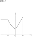
- FIG. 4 is a schematic view of a control map showing an example of the relation between the reference current Ib and the stroke velocity Vp.
- the reference setting section 121 calculates the reference current Ib corresponding to the stroke velocity Vp (the stroke velocity Vpf or the stroke velocity Vpr).
- the reference setting section 121 substitutes the stroke velocity Vp into the control map illustrated in FIG. 4 to thereby calculate the reference current Ib.
- the control map shows the relation between the reference current Ib and the stroke velocity Vp, and has been, for example, created based on a rule of thumb and stored in an ROM in advance.
- the stroke velocity Vp is a velocity of the suspension in a compression direction in the control map illustrated in FIG. 4 .
- setting is performed as follows. That is, when the stroke velocity Vp is equal to or higher than a first predetermined velocity V1, an amount of the current increases as the stroke velocity Vp decreases. When the stroke velocity Vp is lower than the first predetermined velocity V1, the amount of the current is constant.
- the stroke velocity Vp is a velocity of the suspension in an extension direction.
- setting is performed as follows. That is, when the stroke velocity Vp is equal to or lower than a second predetermined velocity V2, the amount of the current increases as the stroke velocity Vp increases. When the stroke velocity Vp is higher than the second predetermined velocity V2, the amount of the current is constant.
- the reference setting section 121 sets the reference current Ib. In other words, this means that the reference setting section 121 sets a base damping force corresponding to the stroke velocity Vp.
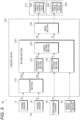
- FIG. 5 is a diagram of a schematic configuration of the correction setting section 122.
- the correction setting section 122 has a reference correction setting section 141 which sets a reference correction current Icb as a reference in setting the correction current Ic.
- the correction setting section 122 has a differential processing section 142 and the multiplication section 143.
- the differential processing section 142 applies differential processing to the longitudinal acceleration Xg detected by the longitudinal G sensor 50 to thereby obtain a differential value DXg of the longitudinal acceleration Xg.
- the multiplication section 143 multiplies the longitudinal acceleration Xg and the differential value DXg to thereby obtain a multiplication value MXg.
- the correction setting section 122 has an absolute value generating section 144 and a coefficient Kd setting section 145.
- the absolute value generating section 144 generates an absolute value of the multiplication value MXg obtained by the multiplication section 143 to thereby obtain the absolute value
- the coefficient Kd setting section 145 sets a deceleration coefficient Kd as a correction coefficient corresponding to the absolute value
- the correction setting section 122 has a coefficient Kj setting section 146 which sets a deceleration determination coefficient Kj as a correction coefficient corresponding to the absolute value of the longitudinal acceleration Xg.
- the correction setting section 122 has a coefficient multiplying section 147 which multiplies the reference correction current Icb set by the reference correction setting section 141, the deceleration coefficient Kd set by the coefficient Kd setting section 145 and the deceleration determination coefficient Kj set by the coefficient Kj setting section 146, to thereby obtain a multiplication value Icbc.
- the correction setting section 122 has a coefficient Kv setting section 148 and a correction current setting section 149.
- the coefficient Kv setting section 148 sets a vehicle speed coefficient Kv as a correction coefficient corresponding to the vehicle speed Vc detected by the vehicle speed detecting section 40.
- the correction current setting section 149 finally sets the correction current Ic based on the multiplication value Icbc obtained by the coefficient multiplying section 147 and the vehicle speed coefficient Kv set by the coefficient Kv setting section 148.
- FIG. 6 is a schematic view of a control map showing an example of the relation between the reference correction current Icb and the stroke velocity Vp.
- the reference correction setting section 141 calculates the reference correction current Icb corresponding to the stroke velocity Vp (the stroke velocity Vpf or the stroke velocity Vpr).
- the reference correction setting section 141 substitutes the stroke velocity Vp into the control map illustrated in FIG. 6 to thereby calculate the reference correction current Icb.
- the control map shows the relation between the reference correction current Icb and the stroke velocity Vp and has been, for example, created based on a rule of thumb and stored in the ROM in advance.
- the stroke velocity Vp is a velocity of the suspension in the compression direction in the control map illustrated in FIG. 6 .
- setting is performed as follows. That is, when the stroke velocity Vp is equal to or higher than a third predetermined velocity V3, an amount of the current increases as the stroke velocity Vp decreases. When the stroke velocity Vp is lower than the third predetermined velocity V3, the amount of the current is constant.
- the stroke velocity Vp is a velocity of the suspension in the extension direction.
- setting is performed as follows. That is, when the stroke velocity Vp is equal to or lower than a fourth predetermined velocity V4, the amount of the current increases as the stroke velocity Vp increases. When the stroke velocity Vp is higher than the fourth predetermined velocity V4, the amount of the current is constant.
- the differential processing section 142 may apply differential processing to the longitudinal acceleration Xg detected by the longitudinal G sensor 50 and extracted by the low pass filter, to thereby calculate the differential value DXg of the longitudinal acceleration Xg.
- the low pass filter is a filter which removes a larger frequency band component than a predetermined frequency (e.g. 5Hz) to thereby extract only a low frequency band component not higher than the predetermined frequency.
- the multiplication section 143 may multiply the longitudinal acceleration Xg detected by the longitudinal G sensor 50 and extracted by the low pass filter and the differential value DXg extracted by the low pass filter, to thereby obtain the multiplication value MXg.
- MXg Xg ⁇ (dXg/dt)
- the absolute value generating section 144 generates an absolute value of the multiplication value MXg calculated by the multiplication section 143, to thereby calculate the absolute value
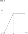
- FIG. 7 is a schematic view of a control map showing an example of the relation between the absolute value
- the coefficient Kd setting section 145 calculates the deceleration coefficient Kd corresponding to the absolute value
- the coefficient Kd setting section 145 substitutes the absolute value
- the control map shows the relation between the absolute value
- setting is made as follows. That is, when the absolute value
- FIG. 8 is a schematic view of a control map showing an example of the relation between the absolute value
- the coefficient Kj setting section 146 calculates the deceleration determination coefficient Kj corresponding to the absolute value
- the coefficient Kj setting section 146 substitutes the absolute value
- the control map shows the relation between the absolute value
- setting is made as follows. That is, when the absolute value
- FIG. 9 is a schematic view of a control map showing an example of the relation between the vehicle speed Vc and the vehicle speed coefficient Kv.
- the coefficient Kv setting section 148 sets the vehicle speed coefficient Kv corresponding to the vehicle speed Vc detected by the vehicle speed detecting section 40.
- the coefficient Kv setting section 148 substitutes the vehicle speed Vc detected by the vehicle speed detecting section 40, into the control map illustrated in FIG. 9 to thereby obtain the vehicle speed coefficient Kv.
- the control map shows the relation between the vehicle speed Vc and the vehicle speed coefficient Kv, and has been, for example, created based on a rule of thumb and stored in the ROM in advance.
- setting is made as follows. That is, when the vehicle speed Vc is equal to or lower than a predetermined vehicle speed Vc1, the vehicle speed coefficient Kv is 0. When the vehicle speed Vc is higher than the predetermined vehicle speed Vc1, the vehicle speed coefficient Kv is 1.
- the reference correction setting section 141, the differential processing section 142, the multiplication section 143, the absolute value generating section 144, the coefficient Kd setting section 145, the coefficient Kj setting section 146, the coefficient multiplying section 147, the coefficient Kv setting section 148 and the correction current setting section 149 respectively perform the aforementioned processes, for example, every predetermined period of time (e.g. every millisecond) repetitively.
- the correction setting section 122 calculates the correction current Ic every predetermined period of time (e.g. every millisecond) to thereby output the calculated correction current Ic to the target setting section 123.
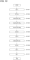
- FIG. 10 is a flow chart showing the sequence of the target current setting process performed by the setting section 120.
- the setting section 120 executes the target current setting process every predetermined period of time (e.g. every millisecond) repetitively.
- the setting section 120 sets a reference current Ib (step (which may be hereinafter referred to as "S") 1001). This is a process in which the reference setting section 121 calculates the reference current Ib as described above.
- the setting section 120 sets a reference correction current Icb (S1002). This is a process in which the reference correction setting section 141 sets the reference correction current Icb.
- the setting section 120 calculates a differential value DXg of a longitudinal acceleration Xg (S1003). This is a process in which the differential processing section 142 calculates the differential value DXg.
- the setting section 120 calculates a multiplication value MXg (S1004). This is a process in which the multiplication section 143 multiplies the longitudinal acceleration Xg detected by the longitudinal G sensor 50 and the differential value DXg calculated in the S1003 to thereby calculate the multiplication value MXg.
- the setting section 120 calculates an absolute value
- the setting section 120 sets a deceleration coefficient Kd (S1006). This is a process in which the coefficient Kd setting section 145 calculates the deceleration coefficient Kd based on the absolute value
- the setting section 120 sets a deceleration determination coefficient Kj (S1007). This is a process in which the coefficient Kj setting section 146 calculates the deceleration determination coefficient Kj based on the absolute value
- the setting section 120 calculates a multiplication value Icbc (S1008). This is a process in which the coefficient multiplying section 147 multiplies the reference correction current Icb calculated in the S1002, the deceleration coefficient Kd set in the S1006 and the deceleration determination coefficient Kj set in the S1007 to thereby calculate the multiplication value Icbc.
- the setting section 120 sets a vehicle speed coefficient Kv (S1009). This is a process in which the coefficient Kv setting section 148 calculates the vehicle speed coefficient Kv based on the vehicle speed Vc as described above.
- the setting section 120 sets a correction current Ic (S1010). This is a process in which the correction current setting section 149 sets a value obtained by multiplying the multiplication value Icbc calculated in the S1008 and the vehicle speed coefficient Kv set in the S1009, as the correction current Ic.
- the setting section 120 sets a target current It (S1011). This is a process in which the target setting section 123 sets a value obtained by adding the reference current Ib set in the S1001 and the correction current Ic set in the S1010, as the target current It.
- the setting section 120 performs the target current setting process to set the target current It.
- the control device 100 controls the damping force of the damping device 200 by the following method.
- the method for controlling the damping force of the damping device 200 damping a force generated between the vehicle body 10 and the wheel is characterized by multiplying the longitudinal acceleration Xg of the vehicle body 10 and the differential value DXg of the longitudinal acceleration Xg to thereby calculate the multiplication value MXg, and controlling the damping force by use of the calculated multiplication value MXg.
- the longitudinal acceleration Xg of the vehicle body 10 is detected by the longitudinal G sensor 50 which is an example of a longitudinal acceleration sensor.
- the damping force may be made larger than the damping force when the absolute value
- the damping force may be made smaller than the damping force when the longitudinal acceleration Xg is higher than the first predetermined value X1.
- a base damping force based on a change velocity of a relative displacement between the vehicle body 10 and the wheel may be corrected by use of the multiplication value MXg, to thereby control the damping force of the damping device 200.
- the base damping force based on the change velocity of the relative displacement between the vehicle body 10 and the wheel may be corrected by use of the multiplication value MXg and the longitudinal acceleration Xg detected by the longitudinal G sensor 50, to thereby control the damping force of the damping device 200.
- the damping force may be made larger than the damping force when the speed of the vehicle body 10 is equal to or lower than the predetermined speed Vc1.
- control device 100 first multiplies the longitudinal acceleration Xg of the vehicle body 10 detected by the longitudinal G sensor 50 and the differential value of the longitudinal acceleration Xg to thereby calculate the multiplication value MXg in the step 1004 shown in FIG. 10 . Then, the control device 100 calculates the absolute value IMXgl of the calculated multiplication value MXg in the step 1005 shown in FIG. 10 , and sets the deceleration coefficient Kd by use of the calculated absolute value
- control device 100 calculates the multiplication value Icbc by use of the calculated deceleration coefficient Kd in the step 1008, sets the correction current Ic by use of the multiplication value Icbc in the step 1010, and sets the target current It by use of the set correction current Ic in the step 1011.
- control device 100 finally sets the target current It by use of the calculated multiplication value MXg to thereby control the damping force of the damping device 200.
- the coefficient Kd setting section 145 sets the deceleration coefficient Kd as 1.
- the coefficient Kd setting section 145 sets the deceleration coefficient Kd as a value smaller than 1. Therefore, when the absolute value
- the control device 100 makes the damping force of the damping device 200 larger than the damping force of the damping device 200 when the absolute value
- the coefficient Kj setting section 146 sets the deceleration determination coefficient Kj as 0.
- the coefficient Kj setting section 146 sets the deceleration determination coefficient Kj as a value larger than 0. Therefore, when the absolute value
- the control device 100 makes the damping force of the damping device 200 smaller than the damping force of the damping device 200 when the longitudinal acceleration Xg is larger than the first predetermined value X1.
- control device 100 calculates the reference current Ib which will be the base of a base damping force in the step 1001 shown in FIG. 10 .
- control device 100 calculates the absolute value
- control device 100 calculates the multiplication value Icbc by use of the deceleration coefficient Kd in the step 1008, and sets the correction current Ic by use of the multiplication value Icbc in the step 1010.
- the control device 100 sets the value obtained by adding the reference current Ib and the correction current Ic, as the target current It in the S1011. In other words, the control device 100 corrects the base damping force by use of the multiplication value MXg to thereby control the damping force of the damping device 200.
- control device 100 calculates the reference current Ib which will be the base of the base damping force in the step 1001 shown in FIG. 10 .
- control device 100 calculates the absolute value
- control device 100 sets the deceleration determination coefficient Kj by use of the absolute value
- the control device 100 sets the correction current Ic by use of the multiplication value Icbc in the step 1010, and sets the value obtained by adding the reference current Ib and the correction current Ic, as the target current It in the S1011. In other words, the control device 100 corrects the base damping force by use of the multiplication value MXg and the longitudinal acceleration Xg to thereby control the damping force of the damping device 200.
- the coefficient Kv setting section 148 sets the vehicle speed coefficient Kv as 1.
- the coefficient Kv setting section 148 sets the vehicle speed coefficient Kv as 0. Therefore, when the vehicle speed Vc is higher than the predetermined vehicle speed Vc1, the control device 100 makes the correction current Ic larger than the correction current Ic when the vehicle speed Vc is equal to or lower than the predetermined vehicle speed Vc1.
- the control device 100 makes the damping force of the damping device 200 larger than the damping force of the damping device 200 when the vehicle speed Vc is equal to or lower than the predetermined vehicle speed Vc1.
- the suspension apparatus 20 is provided with the damping device 200 which damps the force generated between the vehicle body 10 and the wheel, and the control device 100 which serves as an example of a control section controlling the damping force of the damping device 200.
- the control device 100 has the multiplication section 143 as an example of a multiplication section which multiplies the longitudinal acceleration Xg of the vehicle body 10 detected by the longitudinal G sensor 50 and the differential value DXg of the longitudinal acceleration Xg to thereby obtain the multiplication value MXg.
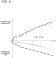
- FIG. 11 is a view showing an example of the relation between the stroke velocity Vp and the damping force. Incidentally, the abscissa shown in FIG. 11 expresses an absolute value of the stroke velocity Vp.
- the control device 100 adds the correction current Ic set by use of the multiplication value MXg or the longitudinal acceleration Xg, to the reference current Ib corresponding to the stroke velocity Vp to thereby set the target current It.
- the amount of the current fed to the solenoid of the damping force control valve 240 increases by the correction current Ic on the occasion of the deceleration. Accordingly, the damping force increases. As a result, nosedive is more difficult to occur than in a case where the correction current Ic is not added in setting the target current It.
- the correction current Ic when the correction current Ic is set by use of the multiplication value MXg, it is possible to distinguish the hard braking from a light brake operation or it is possible to distinguish an occasion of gentle deceleration, an occasion of making a turn or an occasion of passing through a gap in a road surface. Further, when the correction current Ic is set by use of the multiplication value MXg and the longitudinal acceleration Xg, it is possible to distinguish passage through a rough road or a slalom, which cannot be distinguished by only the multiplication value MXg.
- the correction setting section 122 sets the deceleration coefficient Kd based on the absolute value (
- the multiplication value MXg is obtained by multiplying the longitudinal acceleration Xg and the differential value DXg of the longitudinal acceleration Xg.
- the deceleration coefficient Kd is set to be smaller than 1.
- the deceleration coefficient Kd is set as 1.
- the second predetermined multiplication value M2 is set as the aforementioned predetermined value with which the occasion of the hard braking can be distinguished, for example, from any of an occasion of a light brake operation, an occasion of gentle deceleration, an occasion of making a turn and an occasion of passing through a gap in a road surface.
- the correction current Ic on any of the occasion of the light brake operation, the occasion of the gentle deceleration, the occasion of making the turn and the case of passing through the gap in the road surface is smaller than the correction current Ic on the occasion of the hard braking.
- the damping force for example, on any of the occasion of the light brake operation, the occasion of the gentle deceleration, the occasion of making the turn and the occasion of passing through the gap in the road surface is smaller than the damping force on the occasion of the hard braking.
- the deceleration determination coefficient Kj is set based on the absolute value
- the differential value DXg of the longitudinal acceleration Xg takes an excessive value. Therefore, even though it is not the occasion of the sudden deceleration, the multiplication value MXg increases and the correction current Ic increases. As a result, there is a fear that the damping force increases.
- the first predetermined value X1 (e.g. 0.2 G) is set as an upper limit value of the longitudinal acceleration Xg considered to be generated on the occasion of travelling on the rough road or the slalom.
- of the longitudinal acceleration Xg is equal to or smaller than the first predetermined value X1 so that the deceleration determination coefficient Kj is 0. Accordingly, the aforementioned correction current Ic is 0.
- the damping force on the occasion of travelling on the rough road or the slalom can be made smaller than the damping force on the occasion of the sudden deceleration. Accordingly, it is possible to accurately suppress the shock absorbing performance from deteriorating due to the damping force made excessive on the occasion of travelling on the rough road or the slalom.
- setting in the correction setting section 122 is made as follows. That is, when the vehicle speed Vc is equal to or lower than the predetermined vehicle speed Vc1, the vehicle speed coefficient Kv is 0. When the vehicle speed Vc is higher than the predetermined vehicle speed Vc1, the vehicle speed coefficient Kv is 1. Thus, when the vehicle speed Vc is higher than the predetermined vehicle speed Vc1, the damping force can be made larger than the damping force when the vehicle speed Vc is equal to or lower than the predetermined vehicle speed Vc1. When the vehicle speed Vc is equal to or lower than the predetermined vehicle speed Vc1, the correction current can be set as 0. As a result, it is possible to accurately suppress the shock absorbing performance from deteriorating due to the damping force increased on an occasion of parking or travelling at an extremely low speed.
- the suspension apparatus 20 As described above, it is possible to accurately determine whether sudden deceleration has been attempted or not. When the sudden deceleration has been attempted, pitching motion can be settled down smoothly. In addition, while it is possible to smoothly settle down the pitching motion on the occasion of the sudden deceleration, it is possible to accurately suppress shock absorbing performance on any of an occasion of a light brake operation, an occasion of gentle deceleration, an occasion of making a turn, an occasion of passing through a gap in a road surface, an occasion of travelling on a rough road or a slalom, and an occasion of parking or travelling at an extremely low speed.
- the aforementioned process performed by the control device 100 can be carried out by software and hardware resources cooperating with each other.
- a CPU inside a control computer provided in the control device 100 executes a program for implementing the respective functions of the control device 100 to thereby implement the respective functions.
- a non-transitory computer-readable recording medium having the program recorded therein is provided to the control device 100, and the CPU of the control device 100 reads the program stored in the recording medium.
- the program per se read from the recording medium implement the functions of the aforementioned embodiment. Accordingly, the program per se and the recording medium having the program recorded therein constitute the present invention.
- a flexible disk, a CD-ROM, a DVD-ROM, a hard disk, an optical disk, an magnetooptical disk, a CD-R, a magnetic tape, a non-volatile memory card, and an ROM can be enumerated as examples of the recording medium for supplying such a program.
- FIG. 12 is a diagram showing a schematic configuration of a recording medium 300 according to the present embodiment.
- the recording medium 300 is a non-transitory computer-readable recording medium in which a program for making a computer implement a function of controlling a damping force of the damping device 200 has been recorded.
- the recording medium 300 stores a program P.
- the program P includes an Ib setting function 311 of setting a reference current Ib, an Icb setting function 312 of setting a reference correction current Icb, and a DXg calculation function 313 of calculating a differential value DXg of a longitudinal acceleration Xg.
- the program P includes an MXg calculation function 314 of calculating a multiplication value MXg, an
- the program P includes a Kj setting function 317 of setting a deceleration determination coefficient Kj, and an Icbc calculation function 318 of calculating a multiplication value Icbc.
- the program P includes a Kv setting function 319 of setting a vehicle speed coefficient Kv, an Ic setting function 320 of setting a correction current Ic, and an It setting function 321 of setting a target current It.
- the Ib setting function 311 is a module implementing the function of the reference setting section 121 shown in FIG. 3 .
- the Icb setting function 312 is a module implementing the function of the reference correction setting section 141 shown in FIG. 5 .
- the DXg calculation function 313 is a module implementing the function of the differential processing section 142 shown in FIG. 5 .
- the MXg calculation function 314 is a module implementing the function of the multiplication section 143 shown in FIG. 5 .
- calculation function 315 is a module implementing the function of the absolute value generating section 144 shown in FIG. 5 .
- the Kd setting function 316 is a module implementing the function of the coefficient Kd setting section 145 shown in FIG. 5 .
- the Kj setting function 317 is a module implementing the function of the coefficient Kj setting section 146 shown in FIG. 5 .
- the Icbc setting function 318 is a module implementing the function of the coefficient multiplying section 147 shown in FIG. 5 .
- the Kv setting function 319 is a module implementing the function of the coefficient Kv setting section 148 shown in FIG. 5 .
- the Ic setting function 320 is a module implementing the function of the correction current setting section 149 shown in FIG. 5 .
- the It setting function 321 is a module implementing the function of the target setting section 123 shown in FIG. 3 .
- the recording medium 300 is a non-transitory computer-readable recording medium in which the program for making the computer implement the function of controlling the damping force of the damping device 200 has been recorded.
- the recorded program makes the computer implement the function of controlling the damping force of the damping device 200 by use of the multiplication value MXg.
- the multiplication value MXg is obtained by multiplying the longitudinal acceleration Xg of the vehicle body 10 detected by the longitudinal G sensor 50 and the differential value DXg of the longitudinal acceleration Xg.
- the CPU etc. may perform a portion or the whole of an actual process based on an instruction of the program so that the functions of the aforementioned embodiment can be implemented by the process.
- the program of the software implementing the functions of the embodiment is distributed through a network, so that the program of the software can be stored in a recording means such as a hard disk or an ROM of the control device 100 or a recording medium such as a CD-RW or a CD-R.
- the CPU of the control device 100 may read and execute the program stored in the recording means or the recording medium.
- the present invention may set the first predetermined multiplication value M1 and the second predetermined multiplication value M2 as the same value, so as to set the deceleration coefficient Kd as 0 when the absolute value
- the second predetermined multiplication value M2 (the first predetermined multiplication value M1) is set as the aforementioned predetermined value with which an occasion of hard braking can be distinguished from any of an occasion of a light brake operation, an occasion of gentle deceleration, an occasion of making a turn, and an occasion of passing through a gap in a round surface.
- a correction current Ic it is possible to set a correction current Ic to be larger than 0 only on the occasion of the hard braking, and set the correction current Ic as 0 on any of the occasion of the light brake operation, the occasion of the gentle deceleration, the occasion of making the turn, and the occasion of passing through the gap in the road surface.
- the present invention may set the first predetermined value X1 and the second predetermined value X2 as the same value, so as to set the deceleration determination coefficient Kj as 0 when the absolute value
- the first predetermined value X1 (the second predetermined value X2) is set as the longitudinal acceleration Xg (e.g. 0.2 G) on an occasion of travelling on a rough road or a slalom.
- the deceleration determination coefficient Kj is set as 0 on the occasion of travelling on the rough road or the slalom.
- the damping device according to the present invention is not limited to the configuration in which the damping force control valve 240 or the working oil flow paths (e.g. the first oil path 231 etc.) for generating the damping force are provided outside the cylinder 210, as shown in FIG. 2 .
- the damping force control valve 240 or the working oil flow paths for generating the damping force may be disposed inside the cylinder 210.
- the damping device may be provided with a compression-side damping force control valve and an extension-side damping force control valve separately.
- the compression-side damping force control valve changes a damping force (compression-side damping force) generated at a compression stroke.
- the extension-side damping control valve changes a damping force (extension-side damping force) generated at an extension stroke.
Landscapes
- Engineering & Computer Science (AREA)
- Mechanical Engineering (AREA)
- Vehicle Body Suspensions (AREA)
- Axle Suspensions And Sidecars For Cycles (AREA)
Description
- The present invention relates to a suspension apparatus and a recording medium.
- There has been proposed a technique for variably controlling a damping force of a variable damping force damper provided in a suspension (suspension apparatus) of a vehicle in accordance with a motion state of the vehicle. The variable damping force damper is a damper whose damping force can be variably changed.
- For example, an apparatus described in
PTL 1 is configured as follows. That is, the apparatus is a variable damping force damper provided in a suspension apparatus of a vehicle so that a damping force of the damper is variably controlled in accordance with a motion state of the vehicle by a control means, and the control means controls the damping force of the damper based on a differential value of a longitudinal acceleration of the vehicle which is detected by a longitudinal acceleration sensor and then subjected to differential processing by a differential filter. - PTL 2 shows a suspension control device that performs an anti-pitch control of a vehicle body by adjusting a supply and discharge amount of a pressure fluid to and from the cylinder by an operation, by utilizing a longitudinal acceleration sensor for detecting longitudinal acceleration acting on a vehicle body, wherein an acceleration change rate is obtained from data detected by the longitudinal acceleration sensor, and a gain is multiplied by an arbitrary gain to calculate a control signal.
-
- PTL 1:
JP-A-2006-321258 - PTL 2:
JP H03 243412 A - When the damping force is controlled by use of the differential value of the longitudinal acceleration, it is important to accurately determine whether sudden deceleration has been attempted or not, in order to increase the damping force in an early stage without generating any response delay on the occasion of the sudden deceleration. When the sudden deceleration has been attempted, it is preferable to increase the damping force in order to settle down pitching motion smoothly. On the other hand, when the sudden deceleration has not been attempted, it is preferable to suppress shock absorbing performance from deteriorating due to the increase of the damping force.
- An object of the present invention is to provide a suspension apparatus etc. which can accurately determine whether sudden deceleration has been attempted or not, and settle down pitching motion smoothly when the sudden deceleration has been attempted.
- According to the present invention which has been completed for achievement of the foregoing object, there is provided a suspension apparatus including: a damping device which damps a force generated between a vehicle body and a wheel; and a control section which controls a damping force of the damping device; wherein: the control section includes a multiplication section which multiplies a longitudinal acceleration of the vehicle body detected by a longitudinal acceleration sensor and a differential value of the longitudinal acceleration to thereby obtain a multiplication value.
- Here, configuration is made according to
claim 1, so when an absolute value of the multiplication value is equal to or larger than a predetermined value determined in advance, the control section makes the damping force larger than the damping force when the absolute value is smaller than the predetermined value. - Moreover, configuration is made according to
claim 3, so that when the longitudinal acceleration detected by the longitudinal acceleration sensor is equal to or lower than a predetermined acceleration determined in advance, the control section makes the damping force smaller than the damping force when the longitudinal acceleration is higher than the predetermined acceleration, and the control section corrects a base damping force based on a change velocity of a relative displacement between the vehicle body and the wheel by use of the multiplication value, to thereby control the damping force of the damping device, and the control section corrects a base damping force based on a change velocity of a relative displacement between the vehicle body and the wheel by use of the multiplication value and the longitudinal acceleration detected by the longitudinal acceleration sensor, to thereby control the damping force of the damping device. - Further, configuration may be made so that when a speed of the vehicle body is higher than a predetermined speed determined in advance, the control section makes the damping force larger than the damping force when the speed of the vehicle body is equal to or lower than the predetermined speed.
- In addition, according to the present invention, there is provided a non-transitory computer-readable recording medium having a program recorded therein, the program making a computer implement a function in which a damping force of a damping device damping a force generated between a vehicle body and a wheel is controlled by use of a multiplication value obtained by multiplying a longitudinal acceleration of the vehicle body detected by a longitudinal acceleration sensor and a differential value of the longitudinal acceleration.
- According to the present invention, it is possible to provide a suspension apparatus etc. which can accurately determine whether sudden deceleration has been attempted or not, so as to settle down pitching motion smoothly when the abrupt deceleration has been attempted.
-
- [
FIG. 1 ] A view showing a schematic configuration of a motorcycle according to the present embodiment. - [
FIG. 2 ] A view showing a schematic configuration of a damping device. - [
FIG. 3 ] A diagram of a schematic configuration of a control device. - [
FIG. 4 ] A schematic view of a control map showing an example of the relation between a reference current and a stroke velocity. - [
FIG. 5 ] A diagram of a schematic configuration of a correction setting section. - [
FIG. 6 ] A schematic view of a control map showing an example of the relation between a reference correction current and the stroke velocity. - [
FIG. 7 ] A schematic view of a control map showing an example of the relation between an absolute value of a multiplication value and a deceleration coefficient. - [
FIG. 8 ] A schematic view of a control map showing an example of the relation between an absolute value of a longitudinal acceleration and a deceleration determination coefficient. - [
FIG. 9 ] A schematic view of a control map showing an example of the relation between a vehicle speed and a vehicle speed coefficient. - [
FIG. 10 ] A flow chart showing a sequence of a target current setting process performed by a setting section. - [
FIG. 11 ] A view showing an example of the relation between the stroke velocity and a damping force. - [
FIG. 12 ] A diagram showing a schematic configuration of a recording medium according to the present embodiment. - An embodiment of the present invention will be described below in detail with reference to the accompanying drawings.
-
FIG. 1 is a view showing a schematic configuration of amotorcycle 1 according to the present embodiment. - The
motorcycle 1 is provided with a front wheel 2, arear wheel 3, and avehicle body 10. The front wheel 2 is a wheel on a front side. Therear wheel 3 is a wheel on a rear side. Thevehicle body 10 has avehicle body frame 11, handles 12, brake levers 13, aseat 14, etc. Thevehicle body frame 11 forms a frame of themotorcycle 1. - In addition, the
motorcycle 1 has front wheel-side suspensions 21 coupling the front wheel 2 and thevehicle body 10 to each other. In addition, themotorcycle 1 is provided with twobrackets 15 which retain thesuspension 21 disposed on a left side of the front wheel 2 and thesuspension 21 disposed on a right side of the front wheel 2, and ashaft 16 which is disposed between the twobrackets 15. Theshaft 16 is supported on thevehicle body frame 11 rotatably. Eachsuspension 21 is provided with a suspension spring (not shown) absorbing shock applied from a road surface etc. to the front wheel 2, and adamping device 21d damping vibration of the suspension spring. - In addition, the
motorcycle 1 has a rear wheel-side suspension 22 coupling therear wheel 3 and thevehicle body 10 to each other. Thesuspension 22 is provided with asuspension spring 22s absorbing shock applied from the road surface etc. to therear wheel 3, and adamping device 22d damping vibration of thesuspension spring 22s. - In the following description, the
damping device 21d and thedamping device 22d may be generically referred to as "damping device 200". - In addition, the front wheel-
side suspension 21 and the rear wheel-side suspension 22 may be generically referred to as "suspension". In addition, the front wheel 2 and therear wheel 3 may be generically referred to as "wheel". -
FIG. 2 is a view showing a schematic configuration of thedamping device 200.FIG. 3 is a diagram of a schematic configuration of acontrol device 100. - The
motorcycle 1 is provided with thecontrol device 100 controlling damping forces of thedamping device 21d and thedamping device 22d. Output signals from astroke sensor 31 detecting an extension/compression amount of thesuspension 21, and astroke sensor 32 detecting an extension/compression amount of thesuspension 22 are inputted to thecontrol device 100. In the following description, thestroke sensor 31 and thestroke sensor 32 may be generically referred to as "stroke sensor 30". - In addition, a vehicle speed signal v from a vehicle
speed detecting section 40 detecting a vehicle speed Vc which is a movement speed of themotorcycle 1, an output signal a from alongitudinal G sensor 50 as an example of a longitudinal acceleration sensor which detects a longitudinal acceleration, etc. are inputted to thecontrol device 100. The vehiclespeed detecting section 40 detects the vehicle speed Vc based on output values from a rotationangle detecting sensor 41 detecting a rotation angle of the front wheel 2 and a rotationangle detecting sensor 42 detecting a rotation angle of therear wheel 3. - A
suspension apparatus 20 according to the present invention is an apparatus having the suspension (thesuspension 21 and the suspension 22), thestroke sensor 30, the vehiclespeed detecting section 40, thelongitudinal G sensor 50, and thecontrol device 100. - The
damping device 200 is provided with acylinder 210 filled with working oil, apiston 221 received movably inside thecylinder 210, and apiston rod 222 retaining thepiston 221. One side (upper side inFIG. 2 )end portion 210a of thecylinder 210 is coupled to thevehicle body 10. Thepiston rod 222 retains thepiston 221 at its one side end portion, and has the other side (lower side inFIG. 2 )end portion 222a coupled to the wheel. Incidentally, the damping device in the present invention is not limited to such a form. The damping device in the present invention may have a configuration in which the other side end portion of thecylinder 210 is coupled to the wheel, and the other side end portion of thepiston rod 222 retains thepiston 221 while the one side end portion of thepiston rod 222 is coupled to thevehicle body 10. - In the damping
device 200, a compression stroke is performed in order to move thepiston 221 toward thevehicle body 10 side (the upper side inFIG. 2 ) to thereby reduce the entire length of the dampingdevice 200, and an extension stroke is performed in order to move thepiston 221 toward the wheel side (the lower side inFIG. 2 ) to thereby increase the entire length of the dampingdevice 200. - By the
piston 221 received inside thecylinder 210, thecylinder 210 is internally sectioned into a compression-side oil chamber 211 and an extension-side oil chamber 212. Pressure of the working oil in the compression-side oil chamber 211increases in the compression stroke. Pressure of the working oil in the extension-side oil chamber 212 increases in the extension stroke. - The damping
device 200 has afirst oil path 231 which is connected to theoil chamber 211 inside thecylinder 210, and asecond oil path 232 which is connected to theoil chamber 212 inside thecylinder 210. In addition, the dampingdevice 200 has athird oil path 233 which is provided between thefirst oil path 231 and thesecond oil path 232, and a dampingforce control valve 240 which is provided in thethird oil path 233. In addition, the dampingdevice 200 has afirst branch path 251 which connects thefirst oil path 231 and one end portion of thethird oil path 233 to each other, and asecond branch path 252 which connects thefirst oil path 231 and the other end portion of thethird oil path 233 to each other. In addition, the dampingdevice 200 has athird branch path 253 which connects thesecond oil path 232 and the one end portion of thethird oil path 233 to each other, and afourth branch path 254 which connects thesecond oil path 232 and the other end portion of thethird oil path 233 to each other. - In addition, the damping
device 200 has afirst check valve 271 which is provided in thefirst branch path 251 and which allows the working oil to move from thefirst oil path 231 toward thethird oil path 233 and prohibits the working oil from moving from thethird oil path 233 toward thefirst oil path 231. In addition, the dampingdevice 200 has asecond check valve 272 which is provided in thesecond branch path 252 and which allows the working oil to move from thethird oil path 233 toward thefirst oil path 231 and prohibits the working oil from moving from thefirst oil path 231 toward thethird oil path 233. - In addition, the damping
device 200 has athird check valve 273 which is provided in thethird branch path 253 and which allows the working oil to move from thesecond oil path 232 toward thethird oil path 233 and prohibits the working oil from moving from thethird oil path 233 toward thesecond oil path 232. In addition, the dampingdevice 200 has afourth check valve 274 which is provided in thefourth branch path 254 and which allows the working oil to move from thethird oil path 233 toward thesecond oil path 232 and prohibits the working oil from moving from thesecond oil path 232 toward thethird oil path 233. - In addition, the damping
device 200 has areservoir 290 and areservoir passage 291. Thereservoir 290 has a function for storing the working oil and supplying/discharging the working oil. Thereservoir passage 291 connects thereservoir 290 and the other end portion of thethird oil path 233 to each other. - The damping
force control valve 240 has a solenoid. By control of an amount of a current conducted to the solenoid, pressure of the working oil passing through the valve can be controlled. The amount of the current conducted to the solenoid is controlled by thecontrol device 100. When oil pressure of one of theoil chamber 211 and theoil chamber 212 of thecylinder 210 becomes higher than releasing pressure, the dampingforce control valve 240 allows the working oil to flow into the other oil chamber. That is, when the oil pressure of theoil chamber 211 becomes higher than the releasing pressure, the dampingforce control valve 240 allows the working oil to flow into theoil chamber 212. Thus, the dampingforce control valve 240 changes a damping force (compression-side damping force) generated when the dampingdevice 200 is in the compression stroke. In addition, when the oil pressure of theoil chamber 212 becomes higher than the releasing pressure, the dampingforce control valve 240 allows the working oil to flow into theoil chamber 211. Thus, the dampingforce control valve 240 changes a damping force (extension-side damping force) generated when the dampingdevice 200 is in the extension stroke. - More specifically, when the
piston 221 moves toward theoil chamber 211, the oil pressure of theoil chamber 211 increases. The working oil inside theoil chamber 211 moves toward the dampingforce control valve 240 through thefirst oil path 231 and thefirst branch path 251. The pressure of the working oil passing through the dampingforce control valve 240 is adjusted by valve pressure of the dampingforce control valve 240. Thus, the compression-side damping force is adjusted. The working oil passing through the dampingforce control valve 240 flows into theoil chamber 212 through thefourth branch path 254 and thesecond oil path 232. - On the other hand, when the
piston 221 moves toward theoil chamber 212, the oil pressure of theoil chamber 212 increases. The working oil inside theoil chamber 212 moves toward the dampingforce control valve 240 through thesecond oil path 232 and thethird branch path 253. The pressure of the working oil passing through the dampingforce control valve 240 is adjusted by the valve pressure of the dampingforce control valve 240. Thus, the extension-side damping force is adjusted. The working oil passing through the dampingforce control valve 240 flows into theoil chamber 211 through thesecond branch path 252 and thefirst oil path 231. - The
control device 100 is an arithmetic and logic circuit including a CPU, an ROM, an RAM, a backup RAM, etc. - A front wheel-side stroke signal sf in which an extension/compression amount of the
suspension 21 detected by thestroke sensor 31 has been converted into an output signal, and a rear wheel-side stoke signal sr in which an extension/compression amount of thesuspension 22 detected by thestroke sensor 32 has been converted into an output signal are inputted to thecontrol device 100. In addition thereto, the vehicle speed signal v corresponding to the vehicle speed Vc from the vehiclespeed detecting section 40, the output signal g from thelongitudinal G sensor 50, etc. are also inputted to thecontrol device 100. - The
control device 100 is provided with acalculation section 110 which calculates stroke velocities Vpf and Vpr as change velocities of strokes detected by thestroke sensor 30. In addition, thecontrol device 100 is provided with asetting section 120 which sets target currents Itf and Itr fed to the solenoids of the dampingforce control valves 240, based on the stroke velocities Vpf and Vpr calculated by thecalculation section 110, the output signal g corresponding to a longitudinal acceleration Xg detected by thelongitudinal G sensor 50, and the vehicle speed signal v etc. corresponding to the vehicle speed Vc sent from the vehiclespeed detecting section 40. In addition, thecontrol device 100 is provided with adrive section 130 which drives the dampingforce control valves 240. - The
calculation section 110 differentiates an output value from thestroke sensor 31 to thereby calculate the front wheel-side stroke velocity Vpf. In addition, thecalculation section 110 differentiates an output value from thestroke sensor 32 to thereby calculate the rear wheel-side stroke velocity Vpr. The stroke velocity Vpf and the stroke velocity Vpr may be generically referred to as "stroke velocity Vp". - The
drive section 130 is provided with transistors (Field Effect Transistors: FETs) as switching elements, which are, for example, connected between a positive electrode side line of a power supply and coils of the solenoids of the dampingforce control valves 240 respectively. Thedrive section 130 drives gates of the transistors to enable the transistors to perform a switching operation to thereby control drive of the dampingforce control valves 240. - More specifically, the
drive section 130 enables the transistors to perform the switching operation so that target currents fed to the dampingforce control valves 240 can be the target currents Itf and Itr set by thesetting section 120. That is, thedrive section 130 enables a corresponding one of the transistors to perform the switching operation so that the target current fed to the dampingforce control valve 240 of the dampingdevice 21d can be the target current Itf set by thesetting section 120. In addition, thedrive section 130 enables a corresponding one of the transistors to perform the switching operation so that the target current fed to the dampingforce control valve 240 of the dampingdevice 22d can be the target current Itr set by thesetting section 120. - Details of the
setting section 120 will be described below. - Here, when a brake operation (hard braking) is performed by squeezing the
brake lever 13 strongly and for a long time, thevehicle body 10 tends to continue to move forward due to inertia, thereby resulting in occurrence of pitching motion called nosedive with a front portion of thevehicle body 10 down and a rear portion of thevehicle body 10 up. When the nosedive occurs to compress thesuspension 21 suddenly, there is a fear that the front wheel 2 may slip. On the other hand, when the damping force of the dampingdevice 200 is increased in order to suppress the nosedive, there is a fear that the force fails to be applied to the front wheel 2 so that the front wheel may slip or therear wheel 3 may float. Therefore, in order to improve steering stability on the occasion of sudden deceleration, it is important to settle down the pitching motion smoothly. - When the damping force of the damping
device 200 is controlled based on only a value of the longitudinal acceleration Xg detected by thelongitudinal G sensor 50 in order to settle down the pitching motion smoothly on the occasion of the sudden deceleration, a delay occurs in the control. That is, when the deceleration is determined based on only the value of the detected longitudinal acceleration Xg, a delay occurs in grasping the sudden deceleration. Before the sudden deceleration is grasped, the suspension has already initiated a stroke. Therefore, it is difficult to settle down the pitching motion smoothly. Particularly, when the damping force is controlled by use of the output value of thelongitudinal G sensor 50 which has already passed through a low pass filter, a delay occurs in grasping the sudden deceleration. Accordingly, it is difficult to smoothly settle down the pitching motion on the occasion of the deceleration. - On the other hand, when a differential value of the longitudinal acceleration Xg detected by the
longitudinal G sensor 50 is used in order to compensate for the delay, it is possible to quickly grasp that the brake operation has been performed. However, it is difficult to distinguish the hard braking from a light brake operation performed by squeezing thebrake lever 13 weakly or for a short period of time. - In addition, it may be also considered that a damping force as the sum of a damping force corresponding to the longitudinal acceleration Xg and a damping force corresponding to the differential value of the longitudinal acceleration Xg is set as the damping force on the occasion of the sudden deceleration (e.g. a current value as the sum of a current value corresponding to the longitudinal acceleration Xg and a current value corresponding to the differential value of the longitudinal acceleration Xg is fed to the solenoid of the damping
force control valve 240 to thereby generate the damping force on the occasion of the sudden deceleration). However, in the control of such a case, it is considered that the control for the occasion of the sudden deceleration also works in an occasion of gentle deceleration, an occasion of making a turn or an occasion of passing through a gap in a road surface. For example, the suspension does not make a stroke not only immediately after the brake operation but also during deceleration with the fixed longitudinal acceleration Xg after that. Accordingly, there is a fear that the control for the occasion of the sudden deceleration may work despite that it seldom has an effect even if the damping force of the suspension is increased. In addition, when the damping force is increased on the occasion of passing through the gap in the road surface, shock absorbing performance of the suspension deteriorates. - From earnest research which has been made by the present inventor, the following thing has been found out. That is, sudden deceleration is grasped by use of a value obtained by multiplying the longitudinal acceleration Xg and the differential value of the longitudinal acceleration Xg. Accordingly, it is possible to distinguish the hard braking from a light brake operation, and it is possible to distinguish the occasion of gentle deceleration, the occasion of making the turn or the occasion of passing through the gap in the road surface. For example, when the value obtained by multiplying the longitudinal acceleration Xg and the differential value of the longitudinal acceleration Xg exceeds a predetermined value, it is possible to accurately grasp that the brake operation is not the light brake operation, the occasion of gentle deceleration, the occasion of making the turn or the occasion of passing through the gap in the road surface but hard braking.
- Therefore, the
control device 100 according to the present embodiment is characterized by having a differential value multiplication section 143 (seeFIG. 5 ) as an example of a multiplication section which multiplies the longitudinal acceleration Xg of thevehicle body 10 detected by thelongitudinal G sensor 50 and the differential value of the longitudinal acceleration Xg to obtain a multiplication value, in order to settle down the pitching motion smoothly to improve the steering stability on the occasion of the sudden deceleration. - The
setting section 120 will be described more specifically below. - The
setting section 120 sets the front wheel-side target current Itf fed to the solenoid of the dampingforce control valve 240 of the dampingdevice 21d, based on the front wheel-side stroke velocity Vpf calculated by thecalculation section 110 and the output signal g etc. from thelongitudinal G sensor 50. In addition, thesetting section 120 sets the rear wheel-side target current Itr fed to the solenoid of the dampingforce control valve 240 of the dampingdevice 22d, based on the rear wheel-side stroke velocity Vpr calculated by thecalculation section 110 and the output signal g etc. from thelongitudinal G sensor 50. Incidentally, a technique of setting the target current Itf by thesetting section 120 and a technique of setting the target current Itr by thesetting section 120 are similar or the same. In the following description, the target current Itf and the target current Itr may be generically referred to as "target current It". - The
setting section 120 has areference setting section 121 and acorrection setting section 122. Thereference setting section 121 sets a reference current Ib as a reference in setting the target current It. Thecorrection setting section 122 sets a correction current Ic for correcting the reference current Ib in order to increase the damping force on the occasion of the sudden deceleration. - In addition, the
setting section 120 has atarget setting section 123. Thetarget setting section 123 adds the reference current Ib set by thereference setting section 121 and the correction current Ic set by thecorrection setting section 122 to thereby finally set the target current It. -
FIG. 4 is a schematic view of a control map showing an example of the relation between the reference current Ib and the stroke velocity Vp. - The
reference setting section 121 calculates the reference current Ib corresponding to the stroke velocity Vp (the stroke velocity Vpf or the stroke velocity Vpr). Thereference setting section 121 substitutes the stroke velocity Vp into the control map illustrated inFIG. 4 to thereby calculate the reference current Ib. The control map shows the relation between the reference current Ib and the stroke velocity Vp, and has been, for example, created based on a rule of thumb and stored in an ROM in advance. - Assume that the stroke velocity Vp is a velocity of the suspension in a compression direction in the control map illustrated in
FIG. 4 . In this case, setting is performed as follows. That is, when the stroke velocity Vp is equal to or higher than a first predetermined velocity V1, an amount of the current increases as the stroke velocity Vp decreases. When the stroke velocity Vp is lower than the first predetermined velocity V1, the amount of the current is constant. In addition, assume that the stroke velocity Vp is a velocity of the suspension in an extension direction. In this case, setting is performed as follows. That is, when the stroke velocity Vp is equal to or lower than a second predetermined velocity V2, the amount of the current increases as the stroke velocity Vp increases. When the stroke velocity Vp is higher than the second predetermined velocity V2, the amount of the current is constant. - The
reference setting section 121 sets the reference current Ib. In other words, this means that thereference setting section 121 sets a base damping force corresponding to the stroke velocity Vp. -
FIG. 5 is a diagram of a schematic configuration of thecorrection setting section 122. - The
correction setting section 122 has a referencecorrection setting section 141 which sets a reference correction current Icb as a reference in setting the correction current Ic. - In addition, the
correction setting section 122 has adifferential processing section 142 and themultiplication section 143. Thedifferential processing section 142 applies differential processing to the longitudinal acceleration Xg detected by thelongitudinal G sensor 50 to thereby obtain a differential value DXg of the longitudinal acceleration Xg. Themultiplication section 143 multiplies the longitudinal acceleration Xg and the differential value DXg to thereby obtain a multiplication value MXg. - In addition, the
correction setting section 122 has an absolutevalue generating section 144 and a coefficientKd setting section 145. The absolutevalue generating section 144 generates an absolute value of the multiplication value MXg obtained by themultiplication section 143 to thereby obtain the absolute value |MXg|. The coefficientKd setting section 145 sets a deceleration coefficient Kd as a correction coefficient corresponding to the absolute value |MXg| obtained by the absolutevalue generating section 144. - In addition, the
correction setting section 122 has a coefficientKj setting section 146 which sets a deceleration determination coefficient Kj as a correction coefficient corresponding to the absolute value of the longitudinal acceleration Xg. - In addition, the
correction setting section 122 has acoefficient multiplying section 147 which multiplies the reference correction current Icb set by the referencecorrection setting section 141, the deceleration coefficient Kd set by the coefficientKd setting section 145 and the deceleration determination coefficient Kj set by the coefficientKj setting section 146, to thereby obtain a multiplication value Icbc. - In addition, the
correction setting section 122 has a coefficientKv setting section 148 and a correctioncurrent setting section 149. The coefficientKv setting section 148 sets a vehicle speed coefficient Kv as a correction coefficient corresponding to the vehicle speed Vc detected by the vehiclespeed detecting section 40. The correctioncurrent setting section 149 finally sets the correction current Ic based on the multiplication value Icbc obtained by thecoefficient multiplying section 147 and the vehicle speed coefficient Kv set by the coefficientKv setting section 148. -
FIG. 6 is a schematic view of a control map showing an example of the relation between the reference correction current Icb and the stroke velocity Vp. - The reference
correction setting section 141 calculates the reference correction current Icb corresponding to the stroke velocity Vp (the stroke velocity Vpf or the stroke velocity Vpr). The referencecorrection setting section 141 substitutes the stroke velocity Vp into the control map illustrated inFIG. 6 to thereby calculate the reference correction current Icb. The control map shows the relation between the reference correction current Icb and the stroke velocity Vp and has been, for example, created based on a rule of thumb and stored in the ROM in advance. - Assume that the stroke velocity Vp is a velocity of the suspension in the compression direction in the control map illustrated in
FIG. 6 . In this case, setting is performed as follows. That is, when the stroke velocity Vp is equal to or higher than a third predetermined velocity V3, an amount of the current increases as the stroke velocity Vp decreases. When the stroke velocity Vp is lower than the third predetermined velocity V3, the amount of the current is constant. In addition, assume that the stroke velocity Vp is a velocity of the suspension in the extension direction. In this case, setting is performed as follows. That is, when the stroke velocity Vp is equal to or lower than a fourth predetermined velocity V4, the amount of the current increases as the stroke velocity Vp increases. When the stroke velocity Vp is higher than the fourth predetermined velocity V4, the amount of the current is constant. - The
differential processing section 142 applies differential processing to the longitudinal acceleration Xg detected by thelongitudinal G sensor 50 to thereby calculate the differential value DXg of the longitudinal acceleration Xg (DXg = dXg/dt). Incidentally, thedifferential processing section 142 may apply differential processing to the longitudinal acceleration Xg detected by thelongitudinal G sensor 50 and extracted by the low pass filter, to thereby calculate the differential value DXg of the longitudinal acceleration Xg. Thus, it is possible to suppress the differential processing from being applied to the high-frequency longitudinal acceleration Xg during normal travelling irrelevant to the brake operation. Here, the low pass filter is a filter which removes a larger frequency band component than a predetermined frequency (e.g. 5Hz) to thereby extract only a low frequency band component not higher than the predetermined frequency. - The
multiplication section 143 multiplies the longitudinal acceleration Xg detected by thelongitudinal G sensor 50 and the differential value DXg obtained by thedifferential processing section 142 to thereby calculate a multiplication value MXg (MXg = Xg × (dXg/dt)). Incidentally, themultiplication section 143 may multiply the longitudinal acceleration Xg detected by thelongitudinal G sensor 50 and extracted by the low pass filter and the differential value DXg extracted by the low pass filter, to thereby obtain the multiplication value MXg. Thus, it is possible to suppress a situation that the multiplication value MXg is calculated based on the high-frequency longitudinal acceleration Xg during normal travelling irrelevant to the brake operation, or based on the differential value DXg. - The absolute
value generating section 144 generates an absolute value of the multiplication value MXg calculated by themultiplication section 143, to thereby calculate the absolute value |MXg| of the multiplication value MXg. -
FIG. 7 is a schematic view of a control map showing an example of the relation between the absolute value |MXg| and the deceleration coefficient Kd. - The coefficient
Kd setting section 145 calculates the deceleration coefficient Kd corresponding to the absolute value |MXg|. The coefficientKd setting section 145 substitutes the absolute value |MXg| into the control map illustrated inFIG. 7 to thereby calculate the deceleration coefficient Kd. The control map shows the relation between the absolute value |MXg| and the deceleration coefficient Kd, and has been, for example, created based on a rule of thumb and stored in the ROM in advance. - In the control map illustrated in
FIG. 7 , setting is made as follows. That is, when the absolute value |MXg| is equal to or smaller than a first predetermined multiplication value M1, the deceleration coefficient Kd is 0. When the absolute value |MXg| is equal to or larger than a second predetermined multiplication value M2, the deceleration coefficient Kd is 1. Moreover, setting is made as follows. That is, when the absolute value |MXg| is larger than the first predetermined multiplication value M1 and smaller than the second predetermined multiplication value M2, the deceleration coefficient Kd is a value larger than 0 and smaller than 1, and the deceleration coefficient Kd increases as the absolute value |MXg| increases. -
FIG. 8 is a schematic view of a control map showing an example of the relation between the absolute value |Xg| of the longitudinal acceleration Xg and the deceleration determination coefficient Kj. - The coefficient
Kj setting section 146 calculates the deceleration determination coefficient Kj corresponding to the absolute value |Xg|. The coefficientKj setting section 146 substitutes the absolute value |Xg| into the control map illustrated inFIG. 8 to thereby calculate the deceleration determination coefficient Kj. The control map shows the relation between the absolute value |Xg| and the deceleration determination coefficient Kj, and has been, for example, created based on a rule of thumb and stored in the ROM in advance. - In the control map illustrated in
FIG. 8 , setting is made as follows. That is, when the absolute value |Xg| is equal to or smaller than a first predetermined value X1, the deceleration determination coefficient Kj is 0. When the absolute value |Xg| is equal to or larger than a second predetermined value X2, the deceleration determination coefficient Kj is 1. Moreover, setting is made as follows. That is, when the absolute value |Xg| is larger than the first predetermined value X1 and smaller than the second predetermined value X2, the deceleration determination coefficient Kj is a value larger than 0 and smaller than 1, and the deceleration determination coefficient Kj increases as the absolute value |Xg| increases. - The
coefficient multiplying section 147 multiplies the reference correction current Icb set by the referencecorrection setting section 141, the deceleration coefficient Kd set by the coefficientKd setting section 145 and the deceleration determination coefficient Kj set by the coefficientKj setting section 146, to thereby calculate the multiplication value Icbc (Icbc = Icb×Kd×Kj). -
FIG. 9 is a schematic view of a control map showing an example of the relation between the vehicle speed Vc and the vehicle speed coefficient Kv. - The coefficient
Kv setting section 148 sets the vehicle speed coefficient Kv corresponding to the vehicle speed Vc detected by the vehiclespeed detecting section 40. The coefficientKv setting section 148 substitutes the vehicle speed Vc detected by the vehiclespeed detecting section 40, into the control map illustrated inFIG. 9 to thereby obtain the vehicle speed coefficient Kv. The control map shows the relation between the vehicle speed Vc and the vehicle speed coefficient Kv, and has been, for example, created based on a rule of thumb and stored in the ROM in advance. - In the control map illustrated in
FIG. 9 , setting is made as follows. That is, when the vehicle speed Vc is equal to or lower than a predetermined vehicle speed Vc1, the vehicle speed coefficient Kv is 0. When the vehicle speed Vc is higher than the predetermined vehicle speed Vc1, the vehicle speed coefficient Kv is 1. - The correction
current setting section 149 multiplies the multiplication value Icbc calculated by thecoefficient multiplying section 147 and the vehicle speed coefficient Kv set by the coefficientKv setting section 148, to thereby calculate the correction current Ic (Ic = Icbc×Kv = Icb×Kd×Kj×Kv). Accordingly, when a value of at least one of the deceleration coefficient Kd, the deceleration determination coefficient Kj and the vehicle speed coefficient Kv is 0, the correction current Ic is 0. - The reference
correction setting section 141, thedifferential processing section 142, themultiplication section 143, the absolutevalue generating section 144, the coefficientKd setting section 145, the coefficientKj setting section 146, thecoefficient multiplying section 147, the coefficientKv setting section 148 and the correctioncurrent setting section 149 respectively perform the aforementioned processes, for example, every predetermined period of time (e.g. every millisecond) repetitively. In this manner, thecorrection setting section 122 calculates the correction current Ic every predetermined period of time (e.g. every millisecond) to thereby output the calculated correction current Ic to thetarget setting section 123. - The
target setting section 123 sets a value obtained by adding the reference current Ib set by thereference setting section 121 and the correction current Ic set by thecorrection setting section 122, as the target current It (It = Ib+Ic). - Next, a sequence of a target current setting process performed by the
setting section 120 will be described by use of a flow chart. -
FIG. 10 is a flow chart showing the sequence of the target current setting process performed by thesetting section 120. - The
setting section 120 executes the target current setting process every predetermined period of time (e.g. every millisecond) repetitively. - The
setting section 120 sets a reference current Ib (step (which may be hereinafter referred to as "S") 1001). This is a process in which thereference setting section 121 calculates the reference current Ib as described above. - The
setting section 120 sets a reference correction current Icb (S1002). This is a process in which the referencecorrection setting section 141 sets the reference correction current Icb. - The
setting section 120 calculates a differential value DXg of a longitudinal acceleration Xg (S1003). This is a process in which thedifferential processing section 142 calculates the differential value DXg. - The
setting section 120 calculates a multiplication value MXg (S1004). This is a process in which themultiplication section 143 multiplies the longitudinal acceleration Xg detected by thelongitudinal G sensor 50 and the differential value DXg calculated in the S1003 to thereby calculate the multiplication value MXg. - The
setting section 120 calculates an absolute value |MXg| of the multiplication value MXg (S1005). This is a process in which the absolutevalue generating section 144 calculates the absolute value |MXg| of the multiplication value MXg. - The
setting section 120 sets a deceleration coefficient Kd (S1006). This is a process in which the coefficientKd setting section 145 calculates the deceleration coefficient Kd based on the absolute value |MXg| as described above. - The
setting section 120 sets a deceleration determination coefficient Kj (S1007). This is a process in which the coefficientKj setting section 146 calculates the deceleration determination coefficient Kj based on the absolute value |Xg| as described above. - The
setting section 120 calculates a multiplication value Icbc (S1008). This is a process in which thecoefficient multiplying section 147 multiplies the reference correction current Icb calculated in the S1002, the deceleration coefficient Kd set in the S1006 and the deceleration determination coefficient Kj set in the S1007 to thereby calculate the multiplication value Icbc. - The
setting section 120 sets a vehicle speed coefficient Kv (S1009). This is a process in which the coefficientKv setting section 148 calculates the vehicle speed coefficient Kv based on the vehicle speed Vc as described above. - The
setting section 120 sets a correction current Ic (S1010). This is a process in which the correctioncurrent setting section 149 sets a value obtained by multiplying the multiplication value Icbc calculated in the S1008 and the vehicle speed coefficient Kv set in the S1009, as the correction current Ic. - The
setting section 120 sets a target current It (S1011). This is a process in which thetarget setting section 123 sets a value obtained by adding the reference current Ib set in the S1001 and the correction current Ic set in the S1010, as the target current It. - As described above, the
setting section 120 performs the target current setting process to set the target current It. Thus, thecontrol device 100 controls the damping force of the dampingdevice 200 by the following method. - That is, the method for controlling the damping force of the damping
device 200 damping a force generated between thevehicle body 10 and the wheel is characterized by multiplying the longitudinal acceleration Xg of thevehicle body 10 and the differential value DXg of the longitudinal acceleration Xg to thereby calculate the multiplication value MXg, and controlling the damping force by use of the calculated multiplication value MXg. The longitudinal acceleration Xg of thevehicle body 10 is detected by thelongitudinal G sensor 50 which is an example of a longitudinal acceleration sensor. - Here, when the absolute value |MXg| of the multiplication value MXg is equal to or larger than the second predetermined multiplication value M2 which is an example of a predetermined value determined in advance, the damping force may be made larger than the damping force when the absolute value |MXg| is smaller than the second predetermined multiplication value M2.
- In addition, when the longitudinal acceleration Xg detected by the
longitudinal G sensor 50 is equal to or lower than a first predetermined value X1 which is an example of a predetermined acceleration determined in advance, the damping force may be made smaller than the damping force when the longitudinal acceleration Xg is higher than the first predetermined value X1. - In addition, a base damping force based on a change velocity of a relative displacement between the
vehicle body 10 and the wheel may be corrected by use of the multiplication value MXg, to thereby control the damping force of the dampingdevice 200. - In addition, the base damping force based on the change velocity of the relative displacement between the
vehicle body 10 and the wheel may be corrected by use of the multiplication value MXg and the longitudinal acceleration Xg detected by thelongitudinal G sensor 50, to thereby control the damping force of the dampingdevice 200. - In addition, when the speed of the
vehicle body 10 is higher than the predetermined vehicle speed Vc1 which is an example of a predetermined speed determined in advance, the damping force may be made larger than the damping force when the speed of thevehicle body 10 is equal to or lower than the predetermined speed Vc1. - That is, the
control device 100 first multiplies the longitudinal acceleration Xg of thevehicle body 10 detected by thelongitudinal G sensor 50 and the differential value of the longitudinal acceleration Xg to thereby calculate the multiplication value MXg in the step 1004 shown inFIG. 10 . Then, thecontrol device 100 calculates the absolute value IMXgl of the calculated multiplication value MXg in the step 1005 shown inFIG. 10 , and sets the deceleration coefficient Kd by use of the calculated absolute value |MXg| in the step 1006. In addition, thecontrol device 100 calculates the multiplication value Icbc by use of the calculated deceleration coefficient Kd in the step 1008, sets the correction current Ic by use of the multiplication value Icbc in the step 1010, and sets the target current It by use of the set correction current Ic in the step 1011. Thus, thecontrol device 100 finally sets the target current It by use of the calculated multiplication value MXg to thereby control the damping force of the dampingdevice 200. - In addition, as shown in
FIG. 7 , when the absolute value |MXg| is equal to or larger than the second predetermined multiplication value M2, the coefficientKd setting section 145 sets the deceleration coefficient Kd as 1. When the absolute value |MXg| is smaller than the second predetermined multiplication value M2, the coefficientKd setting section 145 sets the deceleration coefficient Kd as a value smaller than 1. Therefore, when the absolute value |MXg| is equal to or larger than the second predetermined multiplication value M2, thecontrol device 100 makes the correction current Ic larger than the correction current Ic when the absolute value |MXg| is smaller than the second predetermined multiplication value M2. As a result, when the absolute value |MXg| is equal to or larger than the second predetermined multiplication value M2, thecontrol device 100 makes the damping force of the dampingdevice 200 larger than the damping force of the dampingdevice 200 when the absolute value |MXg| is smaller than the second predetermined multiplication value M2. - In addition, as shown in
FIG. 8 , when the absolute value |Xg| is equal to or smaller than the first predetermined value X1, the coefficientKj setting section 146 sets the deceleration determination coefficient Kj as 0. When the absolute value |Xg| is larger than the first predetermined value X1, the coefficientKj setting section 146 sets the deceleration determination coefficient Kj as a value larger than 0. Therefore, when the absolute value |Xg| is equal to or smaller than the first predetermined value X1, thecontrol device 100 makes the correction current Ic smaller than the correction current Ic when the absolute value |Xg| is larger than the first predetermined value X1. As a result, when the longitudinal acceleration Xg detected by thelongitudinal G sensor 50 is equal to or smaller than the first predetermined value X1, thecontrol device 100 makes the damping force of the dampingdevice 200 smaller than the damping force of the dampingdevice 200 when the longitudinal acceleration Xg is larger than the first predetermined value X1. - In addition, the
control device 100 calculates the reference current Ib which will be the base of a base damping force in the step 1001 shown inFIG. 10 . In addition, thecontrol device 100 calculates the absolute value |MXg| of the multiplication value MXg in the step 1005, and sets the deceleration coefficient Kd by use of the calculated absolute value |MXg| in the step 1006. In addition, thecontrol device 100 calculates the multiplication value Icbc by use of the deceleration coefficient Kd in the step 1008, and sets the correction current Ic by use of the multiplication value Icbc in the step 1010. In addition, thecontrol device 100 sets the value obtained by adding the reference current Ib and the correction current Ic, as the target current It in the S1011. In other words, thecontrol device 100 corrects the base damping force by use of the multiplication value MXg to thereby control the damping force of the dampingdevice 200. - In addition, the
control device 100 calculates the reference current Ib which will be the base of the base damping force in the step 1001 shown inFIG. 10 . In addition, thecontrol device 100 calculates the absolute value |MXg| of the multiplication value MXg in the step 1005, and sets the deceleration coefficient Kd by use of the calculated absolute value |MXg| in the step 1006. In addition, thecontrol device 100 sets the deceleration determination coefficient Kj by use of the absolute value |Xg| of the longitudinal acceleration Xg in the step 1007, and calculates the multiplication value Icbc by use of the deceleration coefficient Kd and the deceleration determination coefficient Kj in the step 1008. Thecontrol device 100 sets the correction current Ic by use of the multiplication value Icbc in the step 1010, and sets the value obtained by adding the reference current Ib and the correction current Ic, as the target current It in the S1011. In other words, thecontrol device 100 corrects the base damping force by use of the multiplication value MXg and the longitudinal acceleration Xg to thereby control the damping force of the dampingdevice 200. - In addition, as shown in
FIG. 9 , when the vehicle speed Vc is higher than the predetermined vehicle speed Vc1, the coefficientKv setting section 148 sets the vehicle speed coefficient Kv as 1. When the vehicle speed Vc is equal to or lower than the predetermined vehicle speed Vc1, the coefficientKv setting section 148 sets the vehicle speed coefficient Kv as 0. Therefore, when the vehicle speed Vc is higher than the predetermined vehicle speed Vc1, thecontrol device 100 makes the correction current Ic larger than the correction current Ic when the vehicle speed Vc is equal to or lower than the predetermined vehicle speed Vc1. As a result, when the vehicle speed Vc is higher than the predetermined vehicle speed Vc1, thecontrol device 100 makes the damping force of the dampingdevice 200 larger than the damping force of the dampingdevice 200 when the vehicle speed Vc is equal to or lower than the predetermined vehicle speed Vc1. - As described above, the
suspension apparatus 20 according to the present embodiment is provided with the dampingdevice 200 which damps the force generated between thevehicle body 10 and the wheel, and thecontrol device 100 which serves as an example of a control section controlling the damping force of the dampingdevice 200. Thecontrol device 100 has themultiplication section 143 as an example of a multiplication section which multiplies the longitudinal acceleration Xg of thevehicle body 10 detected by thelongitudinal G sensor 50 and the differential value DXg of the longitudinal acceleration Xg to thereby obtain the multiplication value MXg. -
FIG. 11 is a view showing an example of the relation between the stroke velocity Vp and the damping force. Incidentally, the abscissa shown inFIG. 11 expresses an absolute value of the stroke velocity Vp. - The
control device 100 adds the correction current Ic set by use of the multiplication value MXg or the longitudinal acceleration Xg, to the reference current Ib corresponding to the stroke velocity Vp to thereby set the target current It. Thus, as illustrated inFIG. 11 , the amount of the current fed to the solenoid of the dampingforce control valve 240 increases by the correction current Ic on the occasion of the deceleration. Accordingly, the damping force increases. As a result, nosedive is more difficult to occur than in a case where the correction current Ic is not added in setting the target current It. In the present invention, when the correction current Ic is set by use of the multiplication value MXg, it is possible to distinguish the hard braking from a light brake operation or it is possible to distinguish an occasion of gentle deceleration, an occasion of making a turn or an occasion of passing through a gap in a road surface. Further, when the correction current Ic is set by use of the multiplication value MXg and the longitudinal acceleration Xg, it is possible to distinguish passage through a rough road or a slalom, which cannot be distinguished by only the multiplication value MXg. - The
correction setting section 122 according to the present embodiment sets the deceleration coefficient Kd based on the absolute value (|MXg|) of the multiplication value MXg in setting the correction current Ic. The multiplication value MXg is obtained by multiplying the longitudinal acceleration Xg and the differential value DXg of the longitudinal acceleration Xg. As shown inFIG. 7 , when the absolute value |MXg| is equal to or smaller than the second predetermined multiplication value M2, the deceleration coefficient Kd is set to be smaller than 1. When the absolute value |MXg| is larger than the second predetermined multiplication value M2, for example, on an occasion of hard braking, the deceleration coefficient Kd is set as 1. Therefore, when, for example, the second predetermined multiplication value M2 is set as the aforementioned predetermined value with which the occasion of the hard braking can be distinguished, for example, from any of an occasion of a light brake operation, an occasion of gentle deceleration, an occasion of making a turn and an occasion of passing through a gap in a road surface. Thus, the correction current Ic on any of the occasion of the light brake operation, the occasion of the gentle deceleration, the occasion of making the turn and the case of passing through the gap in the road surface is smaller than the correction current Ic on the occasion of the hard braking. Thus, it is possible to increase the damping force on the occasion of the hard braking to settle down the pitching motion smoothly. At the same time, the damping force, for example, on any of the occasion of the light brake operation, the occasion of the gentle deceleration, the occasion of making the turn and the occasion of passing through the gap in the road surface is smaller than the damping force on the occasion of the hard braking. As a result, it is possible to accurately suppress shock absorbing performance from deteriorating due to a side effect accompanying the fact that the pitching motion can be settled down smoothly on the occasion of the hark braking. - In addition, in the
correction setting section 122 according to the present embodiment, the deceleration determination coefficient Kj is set based on the absolute value |Xg| of the longitudinal acceleration Xg. For example, on an occasion of travelling on a rough road or a slalom, the differential value DXg of the longitudinal acceleration Xg takes an excessive value. Therefore, even though it is not the occasion of the sudden deceleration, the multiplication value MXg increases and the correction current Ic increases. As a result, there is a fear that the damping force increases. Therefore, in consideration of the fact that the longitudinal acceleration Xg on the occasion of travelling on the rough road or the slalom is equal to or lower than the longitudinal acceleration Xg on the occasion of the sudden deceleration, for example, the first predetermined value X1 (e.g. 0.2 G) is set as an upper limit value of the longitudinal acceleration Xg considered to be generated on the occasion of travelling on the rough road or the slalom. Thus, on the occasion of travelling on the rough road or the slalom, the absolute value |Xg| of the longitudinal acceleration Xg is equal to or smaller than the first predetermined value X1 so that the deceleration determination coefficient Kj is 0. Accordingly, the aforementioned correction current Ic is 0. As a result, the damping force on the occasion of travelling on the rough road or the slalom can be made smaller than the damping force on the occasion of the sudden deceleration. Accordingly, it is possible to accurately suppress the shock absorbing performance from deteriorating due to the damping force made excessive on the occasion of travelling on the rough road or the slalom. - In addition, setting in the
correction setting section 122 according to the present embodiment is made as follows. That is, when the vehicle speed Vc is equal to or lower than the predetermined vehicle speed Vc1, the vehicle speed coefficient Kv is 0. When the vehicle speed Vc is higher than the predetermined vehicle speed Vc1, the vehicle speed coefficient Kv is 1. Thus, when the vehicle speed Vc is higher than the predetermined vehicle speed Vc1, the damping force can be made larger than the damping force when the vehicle speed Vc is equal to or lower than the predetermined vehicle speed Vc1. When the vehicle speed Vc is equal to or lower than the predetermined vehicle speed Vc1, the correction current can be set as 0. As a result, it is possible to accurately suppress the shock absorbing performance from deteriorating due to the damping force increased on an occasion of parking or travelling at an extremely low speed. - According to the
suspension apparatus 20 according to the present embodiment, as described above, it is possible to accurately determine whether sudden deceleration has been attempted or not. When the sudden deceleration has been attempted, pitching motion can be settled down smoothly. In addition, while it is possible to smoothly settle down the pitching motion on the occasion of the sudden deceleration, it is possible to accurately suppress shock absorbing performance on any of an occasion of a light brake operation, an occasion of gentle deceleration, an occasion of making a turn, an occasion of passing through a gap in a road surface, an occasion of travelling on a rough road or a slalom, and an occasion of parking or travelling at an extremely low speed. - The aforementioned process performed by the
control device 100 can be carried out by software and hardware resources cooperating with each other. In this case, a CPU inside a control computer provided in thecontrol device 100 executes a program for implementing the respective functions of thecontrol device 100 to thereby implement the respective functions. For example, a non-transitory computer-readable recording medium having the program recorded therein is provided to thecontrol device 100, and the CPU of thecontrol device 100 reads the program stored in the recording medium. In this case, the program per se read from the recording medium implement the functions of the aforementioned embodiment. Accordingly, the program per se and the recording medium having the program recorded therein constitute the present invention. For example, a flexible disk, a CD-ROM, a DVD-ROM, a hard disk, an optical disk, an magnetooptical disk, a CD-R, a magnetic tape, a non-volatile memory card, and an ROM can be enumerated as examples of the recording medium for supplying such a program. -
FIG. 12 is a diagram showing a schematic configuration of arecording medium 300 according to the present embodiment. Therecording medium 300 is a non-transitory computer-readable recording medium in which a program for making a computer implement a function of controlling a damping force of the dampingdevice 200 has been recorded. - As shown in
FIG. 12 , therecording medium 300 according to the present embodiment stores a program P. The program P includes anIb setting function 311 of setting a reference current Ib, anIcb setting function 312 of setting a reference correction current Icb, and aDXg calculation function 313 of calculating a differential value DXg of a longitudinal acceleration Xg. In addition, the program P includes anMXg calculation function 314 of calculating a multiplication value MXg, an |MXg|calculation function 315 of calculating an absolute value |MXg|, and aKd setting function 316 of setting a deceleration coefficient Kd. In addition, the program P includes aKj setting function 317 of setting a deceleration determination coefficient Kj, and anIcbc calculation function 318 of calculating a multiplication value Icbc. In addition, the program P includes aKv setting function 319 of setting a vehicle speed coefficient Kv, anIc setting function 320 of setting a correction current Ic, and an It settingfunction 321 of setting a target current It. - The
Ib setting function 311 is a module implementing the function of thereference setting section 121 shown inFIG. 3 . - The
Icb setting function 312 is a module implementing the function of the referencecorrection setting section 141 shown inFIG. 5 . - The
DXg calculation function 313 is a module implementing the function of thedifferential processing section 142 shown inFIG. 5 . - The
MXg calculation function 314 is a module implementing the function of themultiplication section 143 shown inFIG. 5 . - The |MXg|
calculation function 315 is a module implementing the function of the absolutevalue generating section 144 shown inFIG. 5 . - The
Kd setting function 316 is a module implementing the function of the coefficientKd setting section 145 shown inFIG. 5 . - The
Kj setting function 317 is a module implementing the function of the coefficientKj setting section 146 shown inFIG. 5 . - The
Icbc setting function 318 is a module implementing the function of thecoefficient multiplying section 147 shown inFIG. 5 . - The
Kv setting function 319 is a module implementing the function of the coefficientKv setting section 148 shown inFIG. 5 . - The
Ic setting function 320 is a module implementing the function of the correctioncurrent setting section 149 shown inFIG. 5 . - The It setting
function 321 is a module implementing the function of thetarget setting section 123 shown inFIG. 3 . - As described above, the
recording medium 300 according to the present embodiment is a non-transitory computer-readable recording medium in which the program for making the computer implement the function of controlling the damping force of the dampingdevice 200 has been recorded. The recorded program makes the computer implement the function of controlling the damping force of the dampingdevice 200 by use of the multiplication value MXg. The multiplication value MXg is obtained by multiplying the longitudinal acceleration Xg of thevehicle body 10 detected by thelongitudinal G sensor 50 and the differential value DXg of the longitudinal acceleration Xg. - Incidentally, after the program read from the
recording medium 300 may be written into an internal memory of the control computer provided in thecontrol device 100, the CPU etc. may perform a portion or the whole of an actual process based on an instruction of the program so that the functions of the aforementioned embodiment can be implemented by the process. - In addition, the program of the software implementing the functions of the embodiment is distributed through a network, so that the program of the software can be stored in a recording means such as a hard disk or an ROM of the
control device 100 or a recording medium such as a CD-RW or a CD-R. In use, the CPU of thecontrol device 100 may read and execute the program stored in the recording means or the recording medium. - The form in which the deceleration coefficient Kd is set to increase as the absolute value |MXg| increases when the absolute value |MXg| of the multiplication value MXg is larger than the first predetermined multiplication value M1 and smaller than the second predetermined multiplication value M2, as shown in the control map illustrated in
FIG. 7 , has been illustrated in the aforementioned embodiment. However, the present invention is not limited to such a form. For example, the present invention may set the first predetermined multiplication value M1 and the second predetermined multiplication value M2 as the same value, so as to set the deceleration coefficient Kd as 0 when the absolute value |MXg| of the multiplication value MXg is equal to or smaller than the second predetermined multiplication value M2 (the first predetermined multiplication value M1), and set the deceleration coefficient Kd as 1 when the absolute value |MXg| of the multiplication value MXg is larger than the second predetermined multiplication value M2 (the first predetermined multiplication value M1). - The second predetermined multiplication value M2 (the first predetermined multiplication value M1) is set as the aforementioned predetermined value with which an occasion of hard braking can be distinguished from any of an occasion of a light brake operation, an occasion of gentle deceleration, an occasion of making a turn, and an occasion of passing through a gap in a round surface. Thus, it is possible to set a correction current Ic to be larger than 0 only on the occasion of the hard braking, and set the correction current Ic as 0 on any of the occasion of the light brake operation, the occasion of the gentle deceleration, the occasion of making the turn, and the occasion of passing through the gap in the road surface. As a result, it is easy to increase a damping force only on the occasion of the hard braking, and not to increase the damping force on any of the occasion of the light brake operation, the occasion of the gentle deceleration, the occasion of making the turn, and the occasion of passing through the gap in the road surface.
- The form in which the deceleration determination coefficient Kj is set to increase as the absolute value |Xg| increases when the absolute value |Xg| of the longitudinal acceleration Xg is larger than the first predetermined value X1 and smaller than the second predetermined value X2, as shown in the control map illustrated in
FIG. 8 , has been illustrated in the aforementioned embodiment. However, the present invention is not limited to such a form. For example, the present invention may set the first predetermined value X1 and the second predetermined value X2 as the same value, so as to set the deceleration determination coefficient Kj as 0 when the absolute value |Xg| of the longitudinal acceleration Xg is equal to or smaller than the first predetermined value X1 (the second predetermined value X2), and set the deceleration determination coefficient Kj as 1 when the absolute value |Xg| of the longitudinal acceleration Xg is larger than the first predetermined value X1 (the second predetermined value X2). - The first predetermined value X1 (the second predetermined value X2) is set as the longitudinal acceleration Xg (e.g. 0.2 G) on an occasion of travelling on a rough road or a slalom. Thus, it is possible to set the deceleration determination coefficient Kj as 0 on the occasion of travelling on the rough road or the slalom. At the same time, it is possible to set the deceleration determination coefficient Kj at 1 when the occasion of travelling on the rough road or the slalom cannot be accurately determined. As a result, it is possible to suppress shock absorbing performance from deteriorating due to a damping force made excessive on the occasion of travelling on the rough road or the slalom. At the same time, it is possible to increase the damping force on an occasion of sudden deceleration which is not the occasion of travelling on the rough road or the slalom, so as to settle down pitching motion smoothly.
- The damping device according to the present invention is not limited to the configuration in which the damping
force control valve 240 or the working oil flow paths (e.g. thefirst oil path 231 etc.) for generating the damping force are provided outside thecylinder 210, as shown inFIG. 2 . For example, the dampingforce control valve 240 or the working oil flow paths for generating the damping force may be disposed inside thecylinder 210. - In addition, the damping device according to the present invention may be provided with a compression-side damping force control valve and an extension-side damping force control valve separately. The compression-side damping force control valve changes a damping force (compression-side damping force) generated at a compression stroke. The extension-side damping control valve changes a damping force (extension-side damping force) generated at an extension stroke.
- 1... motorcycle, 2... front wheel, 3... rear wheel, 13... brake lever, 20... suspension apparatus, 21... suspension, 22... suspension, 100... control device, 110... calculation section, 120... setting section, 122... correction setting section, 130... drive section, 142... differential processing section, 143... multiplication section, 200... damping device, 240... damping force control valve
Claims (5)
- A suspension apparatus (21, 22) comprising:a damping device (21d, 22d, 200) which damps a force generated between a vehicle body (10) and a wheel (2, 3); anda control section (100) which controls a damping force of the damping device (21d, 22d, 200); characterized in that:
the control section (100) includes a multiplication section (143) which multiplies a longitudinal acceleration (Xg) of the vehicle body (10) detected by a longitudinal acceleration sensor (50) and a differential value (DXg) of the longitudinal acceleration (Xg) to thereby obtain a multiplication value (MXg), and when an absolute value (|MXg|) of the multiplication value (MXg) obtained by the multiplication section (143) is equal to or larger than a predetermined value determined in advance, the control section (100) makes the damping force larger than the damping force when the absolute value (|MXg|) is smaller than the predetermined value. - The suspension apparatus (21, 22) according to Claim 1, wherein:
the control section (100) corrects a base damping force based on a change velocity of a relative displacement between the vehicle body (10) and the wheel (2, 3) by use of the multiplication value, to thereby control the damping force of the damping device (21d, 22d, 200). - A suspension apparatus (21, 22) comprising:a damping device (21d, 22d, 200) which damps a force generated between a vehicle body (10) and a wheel (2, 3); anda control section (100) which controls a damping force of the damping device (21d, 22d, 200); characterized in that:the control section (100) includes a multiplication section (143) which multiplies a longitudinal acceleration (Xg) of the vehicle body (10) detected by a longitudinal acceleration sensor (50) and a differential value (DXg) of the longitudinal acceleration (Xg) to thereby obtain a multiplication value (MXg);when the longitudinal acceleration (Xg) detected by the longitudinal acceleration sensor (50) is equal to or lower than a predetermined acceleration determined in advance, the control section (100) makes the damping force smaller than the damping force when the longitudinal acceleration (Xg) is higher than the predetermined acceleration; andthe control section (100) corrects a base damping force based on a change velocity of a relative displacement between the vehicle body (10) and the wheel (2, 3) by use of the multiplication value (MXg) and the longitudinal acceleration (Xg) detected by the longitudinal acceleration sensor (50), to thereby control the damping force.
- The suspension apparatus (21, 22) according to Claim 2 or 3, wherein:the control section (100) adds a correction damping force for correcting the base damping force to the base damping force to thereby correct the base damping force; andthe control section (100) corrects a reference correction damping force corresponding to the change velocity by use of a correction coefficient (Kd) corresponding to an absolute value (|MXg|) of the multiplication value (MXg), a correction coefficient (Kj) corresponding to an absolute value (|Xg|) of the longitudinal acceleration (Xg), and a correction coefficient (Kv) corresponding to a speed (Vc) of the vehicle body (10) to thereby calculate the correction damping force.
- The suspension apparatus (21, 22) according to any one of Claims 1, 2, 3 and 4 wherein:
when a speed (Vc) of the vehicle body (10) is higher than a predetermined speed determined in advance, the control section (100) makes the damping force larger than the damping force when the speed (Vc) of the vehicle body (10) is equal to or lower than the predetermined speed.
Applications Claiming Priority (2)
| Application Number | Priority Date | Filing Date | Title |
|---|---|---|---|
| JP2017131972A JP6254323B1 (en) | 2017-07-05 | 2017-07-05 | Suspension device and recording medium |
| PCT/JP2017/025768 WO2019008777A1 (en) | 2017-07-05 | 2017-07-14 | Suspension device and recording medium |
Publications (3)
| Publication Number | Publication Date |
|---|---|
| EP3650251A1 EP3650251A1 (en) | 2020-05-13 |
| EP3650251A4 EP3650251A4 (en) | 2021-03-17 |
| EP3650251B1 true EP3650251B1 (en) | 2023-06-28 |
Family
ID=60860145
Family Applications (1)
| Application Number | Title | Priority Date | Filing Date |
|---|---|---|---|
| EP17916887.7A Active EP3650251B1 (en) | 2017-07-05 | 2017-07-14 | Suspension device and recording medium |
Country Status (4)
| Country | Link |
|---|---|
| US (1) | US11613151B2 (en) |
| EP (1) | EP3650251B1 (en) |
| JP (1) | JP6254323B1 (en) |
| WO (1) | WO2019008777A1 (en) |
Families Citing this family (2)
| Publication number | Priority date | Publication date | Assignee | Title |
|---|---|---|---|---|
| JP6764549B1 (en) * | 2020-02-12 | 2020-09-30 | 株式会社ショーワ | Vehicle height adjustment device, saddle-mounted vehicle |
| WO2021186541A1 (en) | 2020-03-17 | 2021-09-23 | 日立 Astemo 株式会社 | Control device, suspension system, and saddle-type vehicle |
Family Cites Families (12)
| Publication number | Priority date | Publication date | Assignee | Title |
|---|---|---|---|---|
| JP2984844B2 (en) * | 1990-02-20 | 1999-11-29 | トキコ株式会社 | Suspension control device |
| JPH072130A (en) * | 1993-06-21 | 1995-01-06 | Fuji Heavy Ind Ltd | Method for controlling rear wheel steering device |
| JP3125603B2 (en) * | 1994-10-07 | 2001-01-22 | トヨタ自動車株式会社 | Suspension control device |
| JP4546323B2 (en) | 2005-05-17 | 2010-09-15 | 本田技研工業株式会社 | Variable damping force damper |
| JP4648125B2 (en) * | 2005-08-05 | 2011-03-09 | 本田技研工業株式会社 | Control device for variable damping force damper |
| FR2890904B1 (en) * | 2005-09-22 | 2007-12-14 | Peugeot Citroen Automobiles Sa | SUSPENSION CONTROL DEVICE, VEHICLE PROVIDED WITH SAME, METHOD OF OBTAINING AND PROGRAM |
| JP4621582B2 (en) * | 2005-12-07 | 2011-01-26 | 本田技研工業株式会社 | Control device for variable damping force damper |
| JP5398581B2 (en) * | 2010-02-24 | 2014-01-29 | 日立オートモティブシステムズ株式会社 | Suspension control device |
| JP5572485B2 (en) * | 2010-08-31 | 2014-08-13 | 日立オートモティブシステムズ株式会社 | Suspension control device |
| JP5941886B2 (en) * | 2013-08-30 | 2016-06-29 | 本田技研工業株式会社 | Suspension control device |
| JP6406041B2 (en) | 2015-01-30 | 2018-10-17 | 富士通株式会社 | Information processing apparatus, determination method, and program |
| JP6357127B2 (en) | 2015-03-19 | 2018-07-11 | 本田技研工業株式会社 | Vehicle suspension control device |
-
2017
- 2017-07-05 JP JP2017131972A patent/JP6254323B1/en active Active
- 2017-07-14 EP EP17916887.7A patent/EP3650251B1/en active Active
- 2017-07-14 WO PCT/JP2017/025768 patent/WO2019008777A1/en not_active Ceased
-
2019
- 2019-10-30 US US16/669,153 patent/US11613151B2/en active Active
Also Published As
| Publication number | Publication date |
|---|---|
| EP3650251A4 (en) | 2021-03-17 |
| EP3650251A1 (en) | 2020-05-13 |
| WO2019008777A1 (en) | 2019-01-10 |
| JP2019014341A (en) | 2019-01-31 |
| JP6254323B1 (en) | 2017-12-27 |
| US20200062070A1 (en) | 2020-02-27 |
| US11613151B2 (en) | 2023-03-28 |
Similar Documents
| Publication | Publication Date | Title |
|---|---|---|
| KR101826356B1 (en) | Suspension control apparatus | |
| CN102205781B (en) | Suspension control apparatus and vehicle control apparatus | |
| KR20190099487A (en) | Vehicle behavior control device | |
| US11712940B2 (en) | Suspension device and recording medium | |
| US11230155B2 (en) | Control apparatus for suspension apparatus and suspension system | |
| US20210016620A1 (en) | Controlling damper friction effects in a suspension | |
| JP6646376B2 (en) | Control device and suspension device for shock absorber | |
| EP3650251B1 (en) | Suspension device and recording medium | |
| JP5834368B2 (en) | Damper control device | |
| JP6744733B2 (en) | Shock absorber control device and suspension device | |
| JP5702200B2 (en) | Shock absorber controller | |
| EP3901020A1 (en) | Control device, suspension system | |
| JP2015083469A (en) | Suspension device | |
| JP4648055B2 (en) | Control device for variable damping force damper in vehicle | |
| JP5571515B2 (en) | Suspension control device | |
| JPWO2020161806A1 (en) | Control device, suspension system | |
| JP4546323B2 (en) | Variable damping force damper | |
| US12269553B2 (en) | Control device, suspension system, and saddle-type vehicle | |
| JP5519373B2 (en) | Suspension control device and vehicle control device | |
| US20160052360A1 (en) | Damper control device | |
| JPH115420A (en) | Vehicle suspension system |
Legal Events
| Date | Code | Title | Description |
|---|---|---|---|
| STAA | Information on the status of an ep patent application or granted ep patent |
Free format text: STATUS: THE INTERNATIONAL PUBLICATION HAS BEEN MADE |
|
| PUAI | Public reference made under article 153(3) epc to a published international application that has entered the european phase |
Free format text: ORIGINAL CODE: 0009012 |
|
| STAA | Information on the status of an ep patent application or granted ep patent |
Free format text: STATUS: REQUEST FOR EXAMINATION WAS MADE |
|
| 17P | Request for examination filed |
Effective date: 20191114 |
|
| AK | Designated contracting states |
Kind code of ref document: A1 Designated state(s): AL AT BE BG CH CY CZ DE DK EE ES FI FR GB GR HR HU IE IS IT LI LT LU LV MC MK MT NL NO PL PT RO RS SE SI SK SM TR |
|
| AX | Request for extension of the european patent |
Extension state: BA ME |
|
| DAV | Request for validation of the european patent (deleted) | ||
| DAX | Request for extension of the european patent (deleted) | ||
| A4 | Supplementary search report drawn up and despatched |
Effective date: 20210217 |
|
| RIC1 | Information provided on ipc code assigned before grant |
Ipc: B60G 17/018 20060101ALI20210211BHEP Ipc: B60G 17/08 20060101ALI20210211BHEP Ipc: B60G 17/015 20060101AFI20210211BHEP Ipc: B60G 17/016 20060101ALI20210211BHEP Ipc: B62K 25/04 20060101ALI20210211BHEP Ipc: B62K 25/28 20060101ALI20210211BHEP |
|
| RAP1 | Party data changed (applicant data changed or rights of an application transferred) |
Owner name: HITACHI AUTOMOTIVE SYSTEMS, LTD. |
|
| RAP1 | Party data changed (applicant data changed or rights of an application transferred) |
Owner name: HITACHI ASTEMO, LTD. |
|
| GRAP | Despatch of communication of intention to grant a patent |
Free format text: ORIGINAL CODE: EPIDOSNIGR1 |
|
| STAA | Information on the status of an ep patent application or granted ep patent |
Free format text: STATUS: GRANT OF PATENT IS INTENDED |
|
| GRAS | Grant fee paid |
Free format text: ORIGINAL CODE: EPIDOSNIGR3 |
|
| INTG | Intention to grant announced |
Effective date: 20230302 |
|
| GRAA | (expected) grant |
Free format text: ORIGINAL CODE: 0009210 |
|
| STAA | Information on the status of an ep patent application or granted ep patent |
Free format text: STATUS: THE PATENT HAS BEEN GRANTED |
|
| AK | Designated contracting states |
Kind code of ref document: B1 Designated state(s): AL AT BE BG CH CY CZ DE DK EE ES FI FR GB GR HR HU IE IS IT LI LT LU LV MC MK MT NL NO PL PT RO RS SE SI SK SM TR |
|
| RIN1 | Information on inventor provided before grant (corrected) |
Inventor name: SUZUKI, KOTA Inventor name: FUKAZAWA, TAIJI |
|
| REG | Reference to a national code |
Ref country code: CH Ref legal event code: EP |
|
| REG | Reference to a national code |
Ref country code: AT Ref legal event code: REF Ref document number: 1582408 Country of ref document: AT Kind code of ref document: T Effective date: 20230715 |
|
| REG | Reference to a national code |
Ref country code: IE Ref legal event code: FG4D |
|
| REG | Reference to a national code |
Ref country code: DE Ref legal event code: R096 Ref document number: 602017070828 Country of ref document: DE |
|
| REG | Reference to a national code |
Ref country code: LT Ref legal event code: MG9D |
|
| PG25 | Lapsed in a contracting state [announced via postgrant information from national office to epo] |
Ref country code: SE Free format text: LAPSE BECAUSE OF FAILURE TO SUBMIT A TRANSLATION OF THE DESCRIPTION OR TO PAY THE FEE WITHIN THE PRESCRIBED TIME-LIMIT Effective date: 20230628 Ref country code: NO Free format text: LAPSE BECAUSE OF FAILURE TO SUBMIT A TRANSLATION OF THE DESCRIPTION OR TO PAY THE FEE WITHIN THE PRESCRIBED TIME-LIMIT Effective date: 20230928 |
|
| REG | Reference to a national code |
Ref country code: NL Ref legal event code: MP Effective date: 20230628 |
|
| REG | Reference to a national code |
Ref country code: AT Ref legal event code: MK05 Ref document number: 1582408 Country of ref document: AT Kind code of ref document: T Effective date: 20230628 |
|
| PG25 | Lapsed in a contracting state [announced via postgrant information from national office to epo] |
Ref country code: RS Free format text: LAPSE BECAUSE OF FAILURE TO SUBMIT A TRANSLATION OF THE DESCRIPTION OR TO PAY THE FEE WITHIN THE PRESCRIBED TIME-LIMIT Effective date: 20230628 Ref country code: NL Free format text: LAPSE BECAUSE OF FAILURE TO SUBMIT A TRANSLATION OF THE DESCRIPTION OR TO PAY THE FEE WITHIN THE PRESCRIBED TIME-LIMIT Effective date: 20230628 Ref country code: LV Free format text: LAPSE BECAUSE OF FAILURE TO SUBMIT A TRANSLATION OF THE DESCRIPTION OR TO PAY THE FEE WITHIN THE PRESCRIBED TIME-LIMIT Effective date: 20230628 Ref country code: LT Free format text: LAPSE BECAUSE OF FAILURE TO SUBMIT A TRANSLATION OF THE DESCRIPTION OR TO PAY THE FEE WITHIN THE PRESCRIBED TIME-LIMIT Effective date: 20230628 Ref country code: HR Free format text: LAPSE BECAUSE OF FAILURE TO SUBMIT A TRANSLATION OF THE DESCRIPTION OR TO PAY THE FEE WITHIN THE PRESCRIBED TIME-LIMIT Effective date: 20230628 Ref country code: GR Free format text: LAPSE BECAUSE OF FAILURE TO SUBMIT A TRANSLATION OF THE DESCRIPTION OR TO PAY THE FEE WITHIN THE PRESCRIBED TIME-LIMIT Effective date: 20230929 |
|
| PG25 | Lapsed in a contracting state [announced via postgrant information from national office to epo] |
Ref country code: FI Free format text: LAPSE BECAUSE OF FAILURE TO SUBMIT A TRANSLATION OF THE DESCRIPTION OR TO PAY THE FEE WITHIN THE PRESCRIBED TIME-LIMIT Effective date: 20230628 |
|
| PG25 | Lapsed in a contracting state [announced via postgrant information from national office to epo] |
Ref country code: SK Free format text: LAPSE BECAUSE OF FAILURE TO SUBMIT A TRANSLATION OF THE DESCRIPTION OR TO PAY THE FEE WITHIN THE PRESCRIBED TIME-LIMIT Effective date: 20230628 |
|
| PG25 | Lapsed in a contracting state [announced via postgrant information from national office to epo] |
Ref country code: ES Free format text: LAPSE BECAUSE OF FAILURE TO SUBMIT A TRANSLATION OF THE DESCRIPTION OR TO PAY THE FEE WITHIN THE PRESCRIBED TIME-LIMIT Effective date: 20230628 |
|
| PG25 | Lapsed in a contracting state [announced via postgrant information from national office to epo] |
Ref country code: IS Free format text: LAPSE BECAUSE OF FAILURE TO SUBMIT A TRANSLATION OF THE DESCRIPTION OR TO PAY THE FEE WITHIN THE PRESCRIBED TIME-LIMIT Effective date: 20231028 |
|
| PG25 | Lapsed in a contracting state [announced via postgrant information from national office to epo] |
Ref country code: SM Free format text: LAPSE BECAUSE OF FAILURE TO SUBMIT A TRANSLATION OF THE DESCRIPTION OR TO PAY THE FEE WITHIN THE PRESCRIBED TIME-LIMIT Effective date: 20230628 Ref country code: SK Free format text: LAPSE BECAUSE OF FAILURE TO SUBMIT A TRANSLATION OF THE DESCRIPTION OR TO PAY THE FEE WITHIN THE PRESCRIBED TIME-LIMIT Effective date: 20230628 Ref country code: RO Free format text: LAPSE BECAUSE OF FAILURE TO SUBMIT A TRANSLATION OF THE DESCRIPTION OR TO PAY THE FEE WITHIN THE PRESCRIBED TIME-LIMIT Effective date: 20230628 Ref country code: PT Free format text: LAPSE BECAUSE OF FAILURE TO SUBMIT A TRANSLATION OF THE DESCRIPTION OR TO PAY THE FEE WITHIN THE PRESCRIBED TIME-LIMIT Effective date: 20231030 Ref country code: IS Free format text: LAPSE BECAUSE OF FAILURE TO SUBMIT A TRANSLATION OF THE DESCRIPTION OR TO PAY THE FEE WITHIN THE PRESCRIBED TIME-LIMIT Effective date: 20231028 Ref country code: ES Free format text: LAPSE BECAUSE OF FAILURE TO SUBMIT A TRANSLATION OF THE DESCRIPTION OR TO PAY THE FEE WITHIN THE PRESCRIBED TIME-LIMIT Effective date: 20230628 Ref country code: EE Free format text: LAPSE BECAUSE OF FAILURE TO SUBMIT A TRANSLATION OF THE DESCRIPTION OR TO PAY THE FEE WITHIN THE PRESCRIBED TIME-LIMIT Effective date: 20230628 Ref country code: CZ Free format text: LAPSE BECAUSE OF FAILURE TO SUBMIT A TRANSLATION OF THE DESCRIPTION OR TO PAY THE FEE WITHIN THE PRESCRIBED TIME-LIMIT Effective date: 20230628 Ref country code: AT Free format text: LAPSE BECAUSE OF FAILURE TO SUBMIT A TRANSLATION OF THE DESCRIPTION OR TO PAY THE FEE WITHIN THE PRESCRIBED TIME-LIMIT Effective date: 20230628 |
|
| PG25 | Lapsed in a contracting state [announced via postgrant information from national office to epo] |
Ref country code: PL Free format text: LAPSE BECAUSE OF FAILURE TO SUBMIT A TRANSLATION OF THE DESCRIPTION OR TO PAY THE FEE WITHIN THE PRESCRIBED TIME-LIMIT Effective date: 20230628 |
|
| REG | Reference to a national code |
Ref country code: CH Ref legal event code: PL |
|
| PG25 | Lapsed in a contracting state [announced via postgrant information from national office to epo] |
Ref country code: MC Free format text: LAPSE BECAUSE OF FAILURE TO SUBMIT A TRANSLATION OF THE DESCRIPTION OR TO PAY THE FEE WITHIN THE PRESCRIBED TIME-LIMIT Effective date: 20230628 |
|
| REG | Reference to a national code |
Ref country code: BE Ref legal event code: MM Effective date: 20230731 |
|
| PG25 | Lapsed in a contracting state [announced via postgrant information from national office to epo] |
Ref country code: LU Free format text: LAPSE BECAUSE OF NON-PAYMENT OF DUE FEES Effective date: 20230714 |
|
| PG25 | Lapsed in a contracting state [announced via postgrant information from national office to epo] |
Ref country code: MC Free format text: LAPSE BECAUSE OF FAILURE TO SUBMIT A TRANSLATION OF THE DESCRIPTION OR TO PAY THE FEE WITHIN THE PRESCRIBED TIME-LIMIT Effective date: 20230628 Ref country code: LU Free format text: LAPSE BECAUSE OF NON-PAYMENT OF DUE FEES Effective date: 20230714 |
|
| REG | Reference to a national code |
Ref country code: DE Ref legal event code: R097 Ref document number: 602017070828 Country of ref document: DE |
|
| REG | Reference to a national code |
Ref country code: IE Ref legal event code: MM4A |
|
| PG25 | Lapsed in a contracting state [announced via postgrant information from national office to epo] |
Ref country code: DK Free format text: LAPSE BECAUSE OF FAILURE TO SUBMIT A TRANSLATION OF THE DESCRIPTION OR TO PAY THE FEE WITHIN THE PRESCRIBED TIME-LIMIT Effective date: 20230628 Ref country code: CH Free format text: LAPSE BECAUSE OF NON-PAYMENT OF DUE FEES Effective date: 20230731 |
|
| PLBE | No opposition filed within time limit |
Free format text: ORIGINAL CODE: 0009261 |
|
| STAA | Information on the status of an ep patent application or granted ep patent |
Free format text: STATUS: NO OPPOSITION FILED WITHIN TIME LIMIT |
|
| PG25 | Lapsed in a contracting state [announced via postgrant information from national office to epo] |
Ref country code: BE Free format text: LAPSE BECAUSE OF NON-PAYMENT OF DUE FEES Effective date: 20230731 |
|
| 26N | No opposition filed |
Effective date: 20240402 |
|
| PG25 | Lapsed in a contracting state [announced via postgrant information from national office to epo] |
Ref country code: IE Free format text: LAPSE BECAUSE OF NON-PAYMENT OF DUE FEES Effective date: 20230714 |
|
| PG25 | Lapsed in a contracting state [announced via postgrant information from national office to epo] |
Ref country code: IE Free format text: LAPSE BECAUSE OF NON-PAYMENT OF DUE FEES Effective date: 20230714 Ref country code: FR Free format text: LAPSE BECAUSE OF NON-PAYMENT OF DUE FEES Effective date: 20230828 Ref country code: SI Free format text: LAPSE BECAUSE OF FAILURE TO SUBMIT A TRANSLATION OF THE DESCRIPTION OR TO PAY THE FEE WITHIN THE PRESCRIBED TIME-LIMIT Effective date: 20230628 |
|
| PG25 | Lapsed in a contracting state [announced via postgrant information from national office to epo] |
Ref country code: BG Free format text: LAPSE BECAUSE OF FAILURE TO SUBMIT A TRANSLATION OF THE DESCRIPTION OR TO PAY THE FEE WITHIN THE PRESCRIBED TIME-LIMIT Effective date: 20230628 |
|
| PG25 | Lapsed in a contracting state [announced via postgrant information from national office to epo] |
Ref country code: BG Free format text: LAPSE BECAUSE OF FAILURE TO SUBMIT A TRANSLATION OF THE DESCRIPTION OR TO PAY THE FEE WITHIN THE PRESCRIBED TIME-LIMIT Effective date: 20230628 |
|
| REG | Reference to a national code |
Ref country code: DE Ref legal event code: R082 Ref document number: 602017070828 Country of ref document: DE Representative=s name: MAUCHER JENKINS PATENTANWAELTE & RECHTSANWAELT, DE |
|
| PGFP | Annual fee paid to national office [announced via postgrant information from national office to epo] |
Ref country code: GB Payment date: 20250529 Year of fee payment: 9 |
|
| PG25 | Lapsed in a contracting state [announced via postgrant information from national office to epo] |
Ref country code: CY Free format text: LAPSE BECAUSE OF FAILURE TO SUBMIT A TRANSLATION OF THE DESCRIPTION OR TO PAY THE FEE WITHIN THE PRESCRIBED TIME-LIMIT; INVALID AB INITIO Effective date: 20170714 |
|
| PG25 | Lapsed in a contracting state [announced via postgrant information from national office to epo] |
Ref country code: HU Free format text: LAPSE BECAUSE OF FAILURE TO SUBMIT A TRANSLATION OF THE DESCRIPTION OR TO PAY THE FEE WITHIN THE PRESCRIBED TIME-LIMIT; INVALID AB INITIO Effective date: 20170714 |
|
| PGFP | Annual fee paid to national office [announced via postgrant information from national office to epo] |
Ref country code: DE Payment date: 20250528 Year of fee payment: 9 |
|
| PGFP | Annual fee paid to national office [announced via postgrant information from national office to epo] |
Ref country code: IT Payment date: 20250623 Year of fee payment: 9 |
|
| PG25 | Lapsed in a contracting state [announced via postgrant information from national office to epo] |
Ref country code: TR Free format text: LAPSE BECAUSE OF FAILURE TO SUBMIT A TRANSLATION OF THE DESCRIPTION OR TO PAY THE FEE WITHIN THE PRESCRIBED TIME-LIMIT Effective date: 20230628 |