EP3650063A1 - Syringe formed from resin, pre-filled syringe, and method for producing syringe formed from resin - Google Patents
Syringe formed from resin, pre-filled syringe, and method for producing syringe formed from resin Download PDFInfo
- Publication number
- EP3650063A1 EP3650063A1 EP18827619.0A EP18827619A EP3650063A1 EP 3650063 A1 EP3650063 A1 EP 3650063A1 EP 18827619 A EP18827619 A EP 18827619A EP 3650063 A1 EP3650063 A1 EP 3650063A1
- Authority
- EP
- European Patent Office
- Prior art keywords
- syringe
- printing layer
- resin
- syringe body
- ink
- Prior art date
- Legal status (The legal status is an assumption and is not a legal conclusion. Google has not performed a legal analysis and makes no representation as to the accuracy of the status listed.)
- Granted
Links
Images


Classifications
-
- B—PERFORMING OPERATIONS; TRANSPORTING
- B05—SPRAYING OR ATOMISING IN GENERAL; APPLYING FLUENT MATERIALS TO SURFACES, IN GENERAL
- B05D—PROCESSES FOR APPLYING FLUENT MATERIALS TO SURFACES, IN GENERAL
- B05D7/00—Processes, other than flocking, specially adapted for applying liquids or other fluent materials to particular surfaces or for applying particular liquids or other fluent materials
- B05D7/02—Processes, other than flocking, specially adapted for applying liquids or other fluent materials to particular surfaces or for applying particular liquids or other fluent materials to macromolecular substances, e.g. rubber
-
- A—HUMAN NECESSITIES
- A61—MEDICAL OR VETERINARY SCIENCE; HYGIENE
- A61M—DEVICES FOR INTRODUCING MEDIA INTO, OR ONTO, THE BODY; DEVICES FOR TRANSDUCING BODY MEDIA OR FOR TAKING MEDIA FROM THE BODY; DEVICES FOR PRODUCING OR ENDING SLEEP OR STUPOR
- A61M5/00—Devices for bringing media into the body in a subcutaneous, intra-vascular or intramuscular way; Accessories therefor, e.g. filling or cleaning devices, arm-rests
- A61M5/178—Syringes
- A61M5/31—Details
- A61M5/3129—Syringe barrels
-
- A—HUMAN NECESSITIES
- A61—MEDICAL OR VETERINARY SCIENCE; HYGIENE
- A61J—CONTAINERS SPECIALLY ADAPTED FOR MEDICAL OR PHARMACEUTICAL PURPOSES; DEVICES OR METHODS SPECIALLY ADAPTED FOR BRINGING PHARMACEUTICAL PRODUCTS INTO PARTICULAR PHYSICAL OR ADMINISTERING FORMS; DEVICES FOR ADMINISTERING FOOD OR MEDICINES ORALLY; BABY COMFORTERS; DEVICES FOR RECEIVING SPITTLE
- A61J1/00—Containers specially adapted for medical or pharmaceutical purposes
- A61J1/05—Containers specially adapted for medical or pharmaceutical purposes for collecting, storing or administering blood, plasma or medical fluids ; Infusion or perfusion containers
-
- A—HUMAN NECESSITIES
- A61—MEDICAL OR VETERINARY SCIENCE; HYGIENE
- A61M—DEVICES FOR INTRODUCING MEDIA INTO, OR ONTO, THE BODY; DEVICES FOR TRANSDUCING BODY MEDIA OR FOR TAKING MEDIA FROM THE BODY; DEVICES FOR PRODUCING OR ENDING SLEEP OR STUPOR
- A61M5/00—Devices for bringing media into the body in a subcutaneous, intra-vascular or intramuscular way; Accessories therefor, e.g. filling or cleaning devices, arm-rests
- A61M5/178—Syringes
- A61M5/24—Ampoule syringes, i.e. syringes with needle for use in combination with replaceable ampoules or carpules, e.g. automatic
-
- A—HUMAN NECESSITIES
- A61—MEDICAL OR VETERINARY SCIENCE; HYGIENE
- A61M—DEVICES FOR INTRODUCING MEDIA INTO, OR ONTO, THE BODY; DEVICES FOR TRANSDUCING BODY MEDIA OR FOR TAKING MEDIA FROM THE BODY; DEVICES FOR PRODUCING OR ENDING SLEEP OR STUPOR
- A61M5/00—Devices for bringing media into the body in a subcutaneous, intra-vascular or intramuscular way; Accessories therefor, e.g. filling or cleaning devices, arm-rests
- A61M5/178—Syringes
- A61M5/28—Syringe ampoules or carpules, i.e. ampoules or carpules provided with a needle
-
- A—HUMAN NECESSITIES
- A61—MEDICAL OR VETERINARY SCIENCE; HYGIENE
- A61M—DEVICES FOR INTRODUCING MEDIA INTO, OR ONTO, THE BODY; DEVICES FOR TRANSDUCING BODY MEDIA OR FOR TAKING MEDIA FROM THE BODY; DEVICES FOR PRODUCING OR ENDING SLEEP OR STUPOR
- A61M5/00—Devices for bringing media into the body in a subcutaneous, intra-vascular or intramuscular way; Accessories therefor, e.g. filling or cleaning devices, arm-rests
- A61M5/178—Syringes
- A61M5/31—Details
-
- C—CHEMISTRY; METALLURGY
- C08—ORGANIC MACROMOLECULAR COMPOUNDS; THEIR PREPARATION OR CHEMICAL WORKING-UP; COMPOSITIONS BASED THEREON
- C08J—WORKING-UP; GENERAL PROCESSES OF COMPOUNDING; AFTER-TREATMENT NOT COVERED BY SUBCLASSES C08B, C08C, C08F, C08G or C08H
- C08J7/00—Chemical treatment or coating of shaped articles made of macromolecular substances
- C08J7/04—Coating
- C08J7/0427—Coating with only one layer of a composition containing a polymer binder
-
- C—CHEMISTRY; METALLURGY
- C09—DYES; PAINTS; POLISHES; NATURAL RESINS; ADHESIVES; COMPOSITIONS NOT OTHERWISE PROVIDED FOR; APPLICATIONS OF MATERIALS NOT OTHERWISE PROVIDED FOR
- C09D—COATING COMPOSITIONS, e.g. PAINTS, VARNISHES OR LACQUERS; FILLING PASTES; CHEMICAL PAINT OR INK REMOVERS; INKS; CORRECTING FLUIDS; WOODSTAINS; PASTES OR SOLIDS FOR COLOURING OR PRINTING; USE OF MATERIALS THEREFOR
- C09D11/00—Inks
- C09D11/02—Printing inks
- C09D11/03—Printing inks characterised by features other than the chemical nature of the binder
- C09D11/033—Printing inks characterised by features other than the chemical nature of the binder characterised by the solvent
-
- C—CHEMISTRY; METALLURGY
- C09—DYES; PAINTS; POLISHES; NATURAL RESINS; ADHESIVES; COMPOSITIONS NOT OTHERWISE PROVIDED FOR; APPLICATIONS OF MATERIALS NOT OTHERWISE PROVIDED FOR
- C09D—COATING COMPOSITIONS, e.g. PAINTS, VARNISHES OR LACQUERS; FILLING PASTES; CHEMICAL PAINT OR INK REMOVERS; INKS; CORRECTING FLUIDS; WOODSTAINS; PASTES OR SOLIDS FOR COLOURING OR PRINTING; USE OF MATERIALS THEREFOR
- C09D11/00—Inks
- C09D11/02—Printing inks
- C09D11/03—Printing inks characterised by features other than the chemical nature of the binder
- C09D11/037—Printing inks characterised by features other than the chemical nature of the binder characterised by the pigment
-
- C—CHEMISTRY; METALLURGY
- C09—DYES; PAINTS; POLISHES; NATURAL RESINS; ADHESIVES; COMPOSITIONS NOT OTHERWISE PROVIDED FOR; APPLICATIONS OF MATERIALS NOT OTHERWISE PROVIDED FOR
- C09D—COATING COMPOSITIONS, e.g. PAINTS, VARNISHES OR LACQUERS; FILLING PASTES; CHEMICAL PAINT OR INK REMOVERS; INKS; CORRECTING FLUIDS; WOODSTAINS; PASTES OR SOLIDS FOR COLOURING OR PRINTING; USE OF MATERIALS THEREFOR
- C09D11/00—Inks
- C09D11/02—Printing inks
- C09D11/10—Printing inks based on artificial resins
- C09D11/106—Printing inks based on artificial resins containing macromolecular compounds obtained by reactions only involving carbon-to-carbon unsaturated bonds
-
- C—CHEMISTRY; METALLURGY
- C09—DYES; PAINTS; POLISHES; NATURAL RESINS; ADHESIVES; COMPOSITIONS NOT OTHERWISE PROVIDED FOR; APPLICATIONS OF MATERIALS NOT OTHERWISE PROVIDED FOR
- C09D—COATING COMPOSITIONS, e.g. PAINTS, VARNISHES OR LACQUERS; FILLING PASTES; CHEMICAL PAINT OR INK REMOVERS; INKS; CORRECTING FLUIDS; WOODSTAINS; PASTES OR SOLIDS FOR COLOURING OR PRINTING; USE OF MATERIALS THEREFOR
- C09D11/00—Inks
- C09D11/02—Printing inks
- C09D11/10—Printing inks based on artificial resins
- C09D11/106—Printing inks based on artificial resins containing macromolecular compounds obtained by reactions only involving carbon-to-carbon unsaturated bonds
- C09D11/108—Hydrocarbon resins
-
- A—HUMAN NECESSITIES
- A61—MEDICAL OR VETERINARY SCIENCE; HYGIENE
- A61L—METHODS OR APPARATUS FOR STERILISING MATERIALS OR OBJECTS IN GENERAL; DISINFECTION, STERILISATION OR DEODORISATION OF AIR; CHEMICAL ASPECTS OF BANDAGES, DRESSINGS, ABSORBENT PADS OR SURGICAL ARTICLES; MATERIALS FOR BANDAGES, DRESSINGS, ABSORBENT PADS OR SURGICAL ARTICLES
- A61L2/00—Disinfection or sterilisation of materials or objects, in general; Accessories therefor
- A61L2/02—Disinfection or sterilisation of materials or objects, in general; Accessories therefor using physical processes
- A61L2/04—Heat
- A61L2/06—Hot gas
- A61L2/07—Steam
-
- A—HUMAN NECESSITIES
- A61—MEDICAL OR VETERINARY SCIENCE; HYGIENE
- A61L—METHODS OR APPARATUS FOR STERILISING MATERIALS OR OBJECTS IN GENERAL; DISINFECTION, STERILISATION OR DEODORISATION OF AIR; CHEMICAL ASPECTS OF BANDAGES, DRESSINGS, ABSORBENT PADS OR SURGICAL ARTICLES; MATERIALS FOR BANDAGES, DRESSINGS, ABSORBENT PADS OR SURGICAL ARTICLES
- A61L2103/00—Materials or objects being the target of disinfection or sterilisation
- A61L2103/15—Laboratory, medical or dentistry appliances, e.g. catheters or sharps
-
- A—HUMAN NECESSITIES
- A61—MEDICAL OR VETERINARY SCIENCE; HYGIENE
- A61M—DEVICES FOR INTRODUCING MEDIA INTO, OR ONTO, THE BODY; DEVICES FOR TRANSDUCING BODY MEDIA OR FOR TAKING MEDIA FROM THE BODY; DEVICES FOR PRODUCING OR ENDING SLEEP OR STUPOR
- A61M5/00—Devices for bringing media into the body in a subcutaneous, intra-vascular or intramuscular way; Accessories therefor, e.g. filling or cleaning devices, arm-rests
- A61M5/178—Syringes
- A61M5/31—Details
- A61M2005/3103—Leak prevention means for distal end of syringes, i.e. syringe end for mounting a needle
- A61M2005/3104—Caps for syringes without needle
-
- A—HUMAN NECESSITIES
- A61—MEDICAL OR VETERINARY SCIENCE; HYGIENE
- A61M—DEVICES FOR INTRODUCING MEDIA INTO, OR ONTO, THE BODY; DEVICES FOR TRANSDUCING BODY MEDIA OR FOR TAKING MEDIA FROM THE BODY; DEVICES FOR PRODUCING OR ENDING SLEEP OR STUPOR
- A61M5/00—Devices for bringing media into the body in a subcutaneous, intra-vascular or intramuscular way; Accessories therefor, e.g. filling or cleaning devices, arm-rests
- A61M5/178—Syringes
- A61M5/31—Details
- A61M2005/3125—Details specific display means, e.g. to indicate dose setting
-
- A—HUMAN NECESSITIES
- A61—MEDICAL OR VETERINARY SCIENCE; HYGIENE
- A61M—DEVICES FOR INTRODUCING MEDIA INTO, OR ONTO, THE BODY; DEVICES FOR TRANSDUCING BODY MEDIA OR FOR TAKING MEDIA FROM THE BODY; DEVICES FOR PRODUCING OR ENDING SLEEP OR STUPOR
- A61M5/00—Devices for bringing media into the body in a subcutaneous, intra-vascular or intramuscular way; Accessories therefor, e.g. filling or cleaning devices, arm-rests
- A61M5/178—Syringes
- A61M5/31—Details
- A61M2005/3125—Details specific display means, e.g. to indicate dose setting
- A61M2005/3126—Specific display means related to dosing
-
- A—HUMAN NECESSITIES
- A61—MEDICAL OR VETERINARY SCIENCE; HYGIENE
- A61M—DEVICES FOR INTRODUCING MEDIA INTO, OR ONTO, THE BODY; DEVICES FOR TRANSDUCING BODY MEDIA OR FOR TAKING MEDIA FROM THE BODY; DEVICES FOR PRODUCING OR ENDING SLEEP OR STUPOR
- A61M5/00—Devices for bringing media into the body in a subcutaneous, intra-vascular or intramuscular way; Accessories therefor, e.g. filling or cleaning devices, arm-rests
- A61M5/178—Syringes
- A61M5/31—Details
- A61M5/3129—Syringe barrels
- A61M2005/3131—Syringe barrels specially adapted for improving sealing or sliding
-
- A—HUMAN NECESSITIES
- A61—MEDICAL OR VETERINARY SCIENCE; HYGIENE
- A61M—DEVICES FOR INTRODUCING MEDIA INTO, OR ONTO, THE BODY; DEVICES FOR TRANSDUCING BODY MEDIA OR FOR TAKING MEDIA FROM THE BODY; DEVICES FOR PRODUCING OR ENDING SLEEP OR STUPOR
- A61M2205/00—General characteristics of the apparatus
- A61M2205/02—General characteristics of the apparatus characterised by a particular materials
- A61M2205/0238—General characteristics of the apparatus characterised by a particular materials the material being a coating or protective layer
-
- A—HUMAN NECESSITIES
- A61—MEDICAL OR VETERINARY SCIENCE; HYGIENE
- A61M—DEVICES FOR INTRODUCING MEDIA INTO, OR ONTO, THE BODY; DEVICES FOR TRANSDUCING BODY MEDIA OR FOR TAKING MEDIA FROM THE BODY; DEVICES FOR PRODUCING OR ENDING SLEEP OR STUPOR
- A61M2205/00—General characteristics of the apparatus
- A61M2205/58—Means for facilitating use, e.g. by people with impaired vision
- A61M2205/583—Means for facilitating use, e.g. by people with impaired vision by visual feedback
-
- A—HUMAN NECESSITIES
- A61—MEDICAL OR VETERINARY SCIENCE; HYGIENE
- A61M—DEVICES FOR INTRODUCING MEDIA INTO, OR ONTO, THE BODY; DEVICES FOR TRANSDUCING BODY MEDIA OR FOR TAKING MEDIA FROM THE BODY; DEVICES FOR PRODUCING OR ENDING SLEEP OR STUPOR
- A61M2205/00—General characteristics of the apparatus
- A61M2205/60—General characteristics of the apparatus with identification means
-
- A—HUMAN NECESSITIES
- A61—MEDICAL OR VETERINARY SCIENCE; HYGIENE
- A61M—DEVICES FOR INTRODUCING MEDIA INTO, OR ONTO, THE BODY; DEVICES FOR TRANSDUCING BODY MEDIA OR FOR TAKING MEDIA FROM THE BODY; DEVICES FOR PRODUCING OR ENDING SLEEP OR STUPOR
- A61M2207/00—Methods of manufacture, assembly or production
-
- B—PERFORMING OPERATIONS; TRANSPORTING
- B05—SPRAYING OR ATOMISING IN GENERAL; APPLYING FLUENT MATERIALS TO SURFACES, IN GENERAL
- B05D—PROCESSES FOR APPLYING FLUENT MATERIALS TO SURFACES, IN GENERAL
- B05D2201/00—Polymeric substrate or laminate
- B05D2201/02—Polymeric substrate
-
- C—CHEMISTRY; METALLURGY
- C08—ORGANIC MACROMOLECULAR COMPOUNDS; THEIR PREPARATION OR CHEMICAL WORKING-UP; COMPOSITIONS BASED THEREON
- C08J—WORKING-UP; GENERAL PROCESSES OF COMPOUNDING; AFTER-TREATMENT NOT COVERED BY SUBCLASSES C08B, C08C, C08F, C08G or C08H
- C08J2323/00—Characterised by the use of homopolymers or copolymers of unsaturated aliphatic hydrocarbons having only one carbon-to-carbon double bond; Derivatives of such polymers
- C08J2323/02—Characterised by the use of homopolymers or copolymers of unsaturated aliphatic hydrocarbons having only one carbon-to-carbon double bond; Derivatives of such polymers not modified by chemical after treatment
- C08J2323/10—Homopolymers or copolymers of propene
- C08J2323/12—Polypropene
-
- C—CHEMISTRY; METALLURGY
- C08—ORGANIC MACROMOLECULAR COMPOUNDS; THEIR PREPARATION OR CHEMICAL WORKING-UP; COMPOSITIONS BASED THEREON
- C08J—WORKING-UP; GENERAL PROCESSES OF COMPOUNDING; AFTER-TREATMENT NOT COVERED BY SUBCLASSES C08B, C08C, C08F, C08G or C08H
- C08J2345/00—Characterised by the use of homopolymers or copolymers of compounds having no unsaturated aliphatic radicals in side chain, and having one or more carbon-to-carbon double bonds in a carbocyclic or in a heterocyclic ring system; Derivatives of such polymers
-
- C—CHEMISTRY; METALLURGY
- C08—ORGANIC MACROMOLECULAR COMPOUNDS; THEIR PREPARATION OR CHEMICAL WORKING-UP; COMPOSITIONS BASED THEREON
- C08J—WORKING-UP; GENERAL PROCESSES OF COMPOUNDING; AFTER-TREATMENT NOT COVERED BY SUBCLASSES C08B, C08C, C08F, C08G or C08H
- C08J2423/00—Characterised by the use of homopolymers or copolymers of unsaturated aliphatic hydrocarbons having only one carbon-to-carbon double bond; Derivatives of such polymers
- C08J2423/02—Characterised by the use of homopolymers or copolymers of unsaturated aliphatic hydrocarbons having only one carbon-to-carbon double bond; Derivatives of such polymers not modified by chemical after treatment
- C08J2423/10—Homopolymers or copolymers of propene
- C08J2423/12—Polypropene
-
- C—CHEMISTRY; METALLURGY
- C08—ORGANIC MACROMOLECULAR COMPOUNDS; THEIR PREPARATION OR CHEMICAL WORKING-UP; COMPOSITIONS BASED THEREON
- C08J—WORKING-UP; GENERAL PROCESSES OF COMPOUNDING; AFTER-TREATMENT NOT COVERED BY SUBCLASSES C08B, C08C, C08F, C08G or C08H
- C08J2423/00—Characterised by the use of homopolymers or copolymers of unsaturated aliphatic hydrocarbons having only one carbon-to-carbon double bond; Derivatives of such polymers
- C08J2423/26—Characterised by the use of homopolymers or copolymers of unsaturated aliphatic hydrocarbons having only one carbon-to-carbon double bond; Derivatives of such polymers modified by chemical after-treatment
- C08J2423/28—Characterised by the use of homopolymers or copolymers of unsaturated aliphatic hydrocarbons having only one carbon-to-carbon double bond; Derivatives of such polymers modified by chemical after-treatment by reaction with halogens or halogen-containing compounds
Definitions
- the present invention relates to a resin-made syringe, a prefilled syringe, and a method for producing a resin-made syringe.
- a prefillable syringe is a syringe for producing a prefilled syringe filled with a medicine and there are mentioned a glass-made syringe and a resin-made syringe.
- the resin-made syringe is lighter than the glass-made syringe, is not broken even if dropped, and also has satisfactory dimensional precision, and thus has received attention as a prefillable syringe in recent years.
- the resin-made syringe is made of a cyclic olefin-based polymer or polyolefin such as polypropylene in order to secure transparency, but since these resins do not have a polar group, such a resin-made syringe is not suitable in a case where graduation for indicating a capacity of a medicine, a medicine name, an expiration date, a logo, a lot number, and the like are directly printed and displayed. Further, when a printing layer printed on a surface of the prefillable syringe is peeled off, there is also considered a concern in that the printing layer is mixed as foreign matters when the medicine is filled.
- a label is pasted (for example, Patent Literature 1).
- graduation for indicating an internal capacity is directly printed on an outer surface of a syringe body.
- Patent Literature 1 JP 2008-272162 A
- an object of the present invention is to provide a resin-made syringe in which a printing layer, such as graduation, which is printed on an outer surface of a syringe body is hardly peeled off, a prefilled syringe, and a method for producing a resin-made syringe.
- a resin-made syringe including a syringe body made of polyolefin and a printing layer printed on at least a part of an outer surface of the syringe body, in which the printing layer has components including chlorinated polypropylene having a degree of chlorination of 15 to 30%, a colorant, and a filler, the outer surface on which the printing layer is printed has a plurality of recessed portions, and each of the plurality of recessed portions has a depth of 50 nm or more and less than 1 ⁇ m and a width of 50 nm or more and less than 1 ⁇ m and is filled with at least one kind of the components of the printing layer.
- the present invention it is possible to provide a resin-made syringe in which a printing layer printed on a syringe body is hardly peeled off, a prefilled syringe, and a method for producing a resin-made syringe.
- the present invention is not limited only to the following embodiments.
- the expression "X to Y" indicating a range means “X or more and Y or less”.
- operations and measurement of physical properties or the like are carried out under the conditions of at room temperature (20 to 25°C)/relative humidity of 40 to 50% RH unless specifically noted.
- Figs. 1 to 4 are views provided for describing a prefilled syringe 1 or a resin-made syringe 10 according to an embodiment of the present invention.
- the prefilled syringe 1 includes, as described in outline with reference to Fig. 1 , a resin-made syringe 10 provided with a syringe body 11, a medicine filled in an accommodating space 16 of the syringe body 11, a cap 20 (corresponding to a sealing member) sealing a distal end opening of the syringe body 11, a gasket 30 slidably disposed in the accommodating space 16 of the syringe body 11, and a plunger 40.
- the prefilled syringe is also called a cartridge in a case where the prefilled syringe is used in a state of being integrated into an administration tool for administering a medicine filled in the syringe body.
- the resin-made syringe 10 is, as described in outline with reference to Fig. 2 , the resin-made syringe 10 including the syringe body 11 made of polyolefin and a printing layer 18 printed on at least a part of an outer surface 17 of the syringe body 11.
- the printing layer 18 has components including chlorinated polypropylene having a degree of chlorination of 15 to 30%, a colorant, and a filler as illustrated in Fig. 4 , and the outer surface 17 on which the printing layer 18 is printed has a plurality of recessed portions 19.
- Each of the plurality of recessed portions 19 has a depth d1 of 50 nm or more and less than 1 ⁇ m and a width d2 of 50 nm or more and less than 1 ⁇ m.
- Each of the plurality of recessed portions 19 is filled with at least one kind of the components of the printing layer 18. With such a configuration, it is possible to provide the resin-made syringe 10 in which the printing layer 18 printed on the syringe body is hardly peeled off.
- the resin-made syringe 10 includes, as illustrated in Figs. 2 and 3 , the syringe body 11 provided with a nozzle portion 13, which discharges a liquid such as a medicine, and the printing layer 18 provided on the outer surface of the syringe body 11.
- the printing layer 18 is a graduation line indicating an internal capacity of the syringe body 11.
- the printing layer 18 is formed directly on the outer surface 17 of the syringe body 11, deviation of the graduation line from an intended position can be extremely reduced within ⁇ 0.1 mm. Therefore, the present invention is suitable for a syringe in which a dosage of a medicine has to be strictly controlled.
- the printing layer 18 may indicate a medicine name, an expiration date, a logo, a lot number, a stop target position or retraction permissible position of the gasket 30, and the like.
- the syringe body 11 includes, as illustrated in Fig. 3 , a flange 12 provided on a proximal end of the syringe body 11, the nozzle portion 13 provided on a distal end of the syringe body 11, and the accommodating space 16 formed inside the syringe body 11.
- the syringe body 11 is, for example, formed in a hollow cylindrical shape.
- the flange 12 is formed to protrude from the outer surface of the proximal end portion of the syringe body 11 to the outside in a radial direction.
- the nozzle portion 13 is provided to protrude in a distal direction.
- the nozzle portion 13 includes a discharge portion 14 discharging a liquid such as a medicine and an attachment portion 15 provided to surround the outer periphery of the discharge portion 14.
- the nozzle portion 13 is formed in a double tube shape as illustrated in Fig. 3 , and the inner tubular portion corresponds to the discharge portion 14 and the outer tubular portion corresponds to the attachment portion 15.
- the distal end of the discharge portion 14 is opened and forms a distal end opening of the syringe body 11.
- the attachment portion 15 is a portion to which other medical instruments such as an injection needle not illustrated are attached, and in this embodiment, is integrally formed with the syringe body 11. As illustrated in Fig. 3 , a female screw, which is screwed with a male screw of a mounting portion of other medical instruments such as an injection needle, is provided in the inner wall surface of the attachment portion 15.
- the attachment portion 15 can be configured as a separate part from other parts in the syringe body 11. Further, the attachment portion 15 may be omitted.
- the accommodating space 16 corresponds to a cavity part which has a cylindrical shape and is provided radially inside the syringe body 11. A medicine or the like is filled in this accommodating space 16 and a gasket is further inserted so that the prefilled syringe 1 can be prepared.
- the accommodating space 16 is formed almost over the entire syringe body 11 along the axial direction of the syringe body 11.
- the cap 20 includes a substantially cylindrical gripping portion 21 and a sealing portion 22 sealing the distal end opening of the syringe body 11 as illustrated in Fig. 3 .
- the sealing portion 22 is fitted to the outer periphery of the nozzle portion 13 of the syringe body 11 so that the cap 20 is attached to the syringe body 11.
- the gripping portion 21 is disposed at the distal side in relation to the attachment portion 15 of the nozzle portion 13 and is a portion which is gripped by a user when the cap 20 is detached from the syringe body 11.
- the syringe body and the sealing member may have a configuration different from the configurations illustrated in Figs. 1 to 3 .
- a hollow puncture needle fixed to the distal end of the syringe body 11 is provided.
- a sealing member which is mounted on the distal portion of the syringe body to cover a puncture needle and seals a distal end opening of the puncture needle, may be used.
- the distal end opening of the puncture needle forms the distal end opening of the syringe body, and the distal portion of the puncture needle is inserted into the sealing member to seal the distal end opening of the puncture needle.
- a sealing member which is fixed to the nozzle portion of the syringe body in a state of not being able to be detached, may be used. In this case, by inserting a medical instrument attached with a needle into the sealing member, the accommodating space and the outside are communicated with each other.
- the syringe body 11 of the present invention is made of polyolefin.
- the syringe made of polyolefin has a technical effect that the syringe is lightweight, is not broken even if dropped, and also has satisfactory dimensional precision
- the polyolefin constituting the syringe body 11 is a cyclo olefin polymer (COP), a cyclo olefin copolymer (COC), or polypropylene (PP).
- COP cyclo olefin polymer
- COC cyclo olefin copolymer
- PP polypropylene
- cyclo olefin polymer polymers obtained by ring-opening polymerization and hydrogenation of a cycloolefin-based monomer, which is ring-opening polymerizable, such as norbornene or cyclotetradodecene are suitably used.
- cyclo olefin copolymer (COC)
- COC cyclo olefin copolymer
- copolymers obtained by using norbornene and olefins such as ethylene as a raw material additional copolymer of a norbornene-based monomer and ⁇ -olefin
- copolymers obtained by using tetracyclododecene and olefins such as ethylene as a raw material
- cyclo olefin polymer for example, ZEONEX Resin manufactured by Zeon Corporation can be used.
- cyclo olefin copolymer for example, APEL Resin manufactured by Mitsui Chemicals, Inc. can be used.
- the resin-made syringe 10 of an embodiment of the present invention includes, as illustrated in Fig. 2 , the syringe body 11 made of polyolefin and the printing layer 18 printed on at least a part of the outer surface 17 of the syringe body 11.
- the printing layer 18 has components including chlorinated polypropylene having a degree of chlorination of 15 to 30%, a colorant, and a filler as illustrated in Fig. 4 , and the outer surface 17 on which the printing layer 18 is printed has a plurality of recessed portions 19.
- Each of the plurality of recessed portions 19 has a depth d1 of 50 nm or more and less than 1 ⁇ m and a width d2 of 50 nm or more and less than 1 ⁇ m.
- Each of the plurality of recessed portions 19 is filled with at least one kind of the components of the printing layer 18. With such a configuration, an anchor effect occurs between the printing layer 18 and the outer surface 17 and an adhesion strength is improved.
- the plurality of recessed portions 19 on the outer surface 17 on which the printing layer 18 is printed are configured by only recessed portions having the depth d1 and the width d2 of 50 nm or more and less than 1 ⁇ m as illustrated in Fig. 4 . Further, according to an embodiment of the present invention, each of the plurality of recessed portions 19 has the depth d1 of 50 to 200 nm and the width d2 of 100 to 500 nm. With such an embodiment, while the mechanical strength of the syringe body 11 is increased, an anchor effect between the printing layer 18 and the outer surface 17 can be increased.
- the outer surface 17 of the syringe body 11 itself is typically flat and smooth without portions considered as the recessed portions 19.
- the outer surface 17 on which the printing layer 18 is printed has deeper recessed portions 19 than those of the outer surface 17 in a near-field region adjacent to the outer surface 17.
- the near-field region is an arbitrary region in the outer surface 17, which is adjacent to the printing layer 18 and has no printing layer 18 printed thereon, of the syringe body 11.
- At least one kind of the components of the printing layer 18 which is filled in each of the plurality of recessed portions 19 is chlorinated polyolefin.
- the printing layer 18 has an adjacent lamellar structure of chlorinated polypropylene adjacent to the outer surface 17 of the syringe body 11. Further, a total axial length of the adjacent lamellar structure of chlorinated polypropylene in the cross-section along the axis of the syringe body 11 is 10% or less of an axial length d5 of the printing layer 18 illustrated in Fig. 4 .
- the lamellar structure of chlorinated polypropylene which weakens the adhesion strength between the outer surface 17 of the syringe body 11 and the printing layer 18 exists only in a very limited range, the adhesion strength between the outer surface 17 of the syringe body 11 and the printing layer 18 can be increased.
- the printing layer 18 may have a lamellar structure of chlorinated polypropylene at a position separate from the outer surface 17 of the syringe body 11, separately from the adjacent lamellar structure.
- the printing layer 18 has a body region separate from an outer edge of the printing layer 18 by 3 ⁇ m (see a length d3 of Fig. 4 ) or more in a direction along the outer surface 17 of the syringe body 11 and a thickness d4 of the printing layer 18 in the body region is 1 to 10 ⁇ m. With such a range, it can be said that the ink is printed at an intended position, and precision as indication becomes favorable.
- the thickness of the printing layer 18 in the body region is more preferably 2 to 8 ⁇ m.
- the outer surface 17 on which the printing layer 18 is printed is not compatible with the printing layer 18.
- the nature and physical property of the material of the syringe body 11 are not changed. Therefore, it is suppressed that a substance derived from the material of the syringe body 11 which is changed by compatibilization is melted in the medicine in the syringe body 11, or the strength of the syringe body 11 is decreased so that the syringe body 11 is easily broken or does not withstand high-pressure steam sterilization.
- a clear interface is present between the outer surface 17 on which the printing layer 18 is printed and the printing layer 18.
- the printing layer 18 is formed by applying an ink to the outer surface 17 of the syringe body 11 made of polyolefin.
- the ink has components including a volatile solvent, which contains a dissolving component dissolving the polyolefin, chlorinated polypropylene having a degree of chlorination of 15 to 30%, a colorant, and a filler.
- a volatile solvent which contains a dissolving component dissolving the polyolefin, chlorinated polypropylene having a degree of chlorination of 15 to 30%, a colorant, and a filler.
- Such an ink is also referred to as an ink of the present invention (or simply referred to as "ink”) in the present specification.
- the ink of the present invention contains chlorinated polypropylene. Further, the degree of chlorination of the chlorinated polypropylene is 15 to 30%. In an embodiment of the present invention, the degree of chlorination is preferably 20 to 29%, more preferably 23 to 28%, and preferably 25 to 27%. With such a range, the desired effects by the present invention can be efficiently provided. In addition, in an embodiment of the present invention, the degree of chlorination is 8.3 to 3.6% with respect to H in a propylene unit [-CH(CH 3 )-CH 2 -] in the chlorinated polypropylene. With such a range, it is possible to form the printing layer 18 which is more hardly peeled off.
- the chlorinated polypropylene is contained in preferably 10 to 35% by mass, more preferably 13 to 30% by mass, and further preferably 16 to 30% by mass in the ink. With such a range, it is possible to form the printing layer 18 which is more hardly peeled off.
- the chlorinated polypropylene which may be used in the present invention may be synthesized with reference to a conventional known method, or if there is a commercially available product, the commercially available product may be purchased and prepared as the chlorinated polypropylene.
- the ink of the present invention contains a colorant.
- the color of the colorant is not particularly limited, but a black ink is used in the printing layer in many cases.
- a black colorant which may be used in the ink of the present invention, for example, carbon black such as furnace black, channel black, acetylene black, thermal black, or lampblack, a magnetic powder such as magnetite or ferrite, and the like are suitable.
- colorants of other colors known colorants usable in the relevant field can be applied.
- the colorant is contained in preferably 3 to 15% by mass and more preferably 5 to 10% by mass in the ink. With such a range, it is possible to form the printing layer 18 which is hardly peeled off and easily visible.
- the ink of the present invention contains a filler.
- a filler By containing a filler, dispersibility of the ink is improved and glossiness can be controlled.
- Types of the filler are also not particularly limited, but the ink may contain, for example, an inorganic filler such as barium sulfate, talc, calcium carbonate, zinc carbonate, Wollastonite, silica, alumina, magnesium oxide, calcium silicate, sodium aluminate, calcium aluminate, sodium aluminosilicate, magnesium silicate, zinc oxide, antimony trioxide, zeolite, hydrotalcite, metallic fiber, metal whisker, ceramic whisker, potassium titanate, boron nitride, or carbon fiber; or an organic filler such as a naturally derived polymer such as starch, cellulose fine particles, or wood powder or modified products thereof.
- barium sulfate may function as an extender pigment and may also function as a stabilizer for preventing a dehydroch
- the filler is contained in preferably 15 to 60% by mass, more preferably 25 to 45% by mass, and further preferably 25 to 35% by mass in the ink. With such a range, it is possible to form the printing layer 18 which is hardly peeled off and has less color unevenness.
- the ink of the present invention contains a volatile solvent which contains a dissolving component dissolving the polyolefin.
- the volatile solvent for example, toluene, trimethylbenzene, cyclohexane, tetrahydrofuran, and the like are suitable.
- the chlorinated polypropylene can be efficiently dissolved in the volatile solvent.
- solubility of the chlorinated polypropylene can be further increased.
- trimethylbenzene is at least one kind of 1,2,4-trimethylbenzene, 1,2,3-trimethylbenzene, and 1,3,5-trimethylbenzene.
- the volatile solvent contains a dissolving component dissolving the polyolefin.
- the dissolving component is an aromatic hydrocarbon having a benzene ring structure and a hydrocarbon side chain and the number of carbon atoms of the hydrocarbon side chain is 2 or more.
- the number of carbon atoms is preferably 2 to 10 and more preferably 2 to 5. With such a range, when the ink is applied to the outer surface 17 of the syringe body 11, the recessed portions 19 can be efficiently formed on the outer surface 17 of the syringe body 11.
- the dissolving component p-cymene, ethylbenzene, and cumene are suitable, and particularly, p-cymene is preferred.
- the volatile solvent is contained in preferably 15 to 40% by mass, more preferably 20 to 35% by mass, and further preferably 20 to 30% by mass (in the case of containing two or more kinds of volatile solvent, the total amount thereof) in the ink.
- the ink preferably contains 15 to 40% by mass of toluene and more preferably contains 20 to 30% by mass of toluene.
- the volatilization rate of the solvent when the ink is applied to the outer surface 17 of the syringe body 11 becomes appropriate, and as a result, it is suppressed that the lamellar structure of the chlorinated polypropylene is excessively formed in the printing layer. Further, a technical effect that the printing layer 18 can be formed without the syringe body 11 being substantially dissolved by toluene is obtained.
- the printing layer 18 preferably contains 14 to 50% by mass of chlorinated polypropylene having a degree of chlorination of 15 to 30%, and more preferably contains 18 to 43% by mass of chlorinated polypropylene having a degree of chlorination of 15 to 30%. Further, according to an embodiment of the present invention, the printing layer 18 preferably contains 4 to 22% by mass of a colorant, and more preferably contains 7 to 14% by mass of a colorant. Further, according to an embodiment of the present invention, the printing layer 18 preferably contains 21 to 86% by mass of a filler, and more preferably contains 35 to 64% by mass of a filler.
- the outer surface 17 of the syringe body 11 is subjected to a sterilization treatment by an autoclave.
- a sterilization treatment by an autoclave since the recessed portion 19 of the syringe body 11 is filled with at least one kind of the components of the printing layer 18, a technical effect that the peeling-off of the printing layer 18 is suppressed even when subjected to autoclave sterilization is obtained.
- the autoclave method will be described later.
- the resin-made syringe 10 is a syringe before a medicine is filled. After the medicine is filled, by providing the cap 20 sealing the distal end opening of the syringe body 11 and the gasket 30 slidably disposed in the accommodating space 16 of the syringe body 11, the resin-made syringe 10 becomes the prefilled syringe 1.
- the prefilled syringe 1 includes the resin-made syringe 10, a medicine filled in the syringe body 11 of the resin-made syringe 10, the cap 20 sealing the distal end opening of the syringe body 11, and the gasket 30 slidably disposed in the syringe body 11. With such a prefilled syringe 1, since a label is not used, a case where the label is peeled off does not occur, and a dosage of a medicine can be strictly controlled.
- the medicine is filled in the syringe body 11 in an amount more than a dose
- the printing layer 18 is a graduation line printed at a position where the internal capacity of the syringe body 11 coincides with the dose of the medicine. Since the printing layer 18 is formed directly on the outer surface 17 of the syringe body 11, deviation of the graduation line from an intended position is extremely reduced. Therefore, when the gasket is moved forward to the graduation line in order to make the amount of the medicine in the syringe body 11 coincide with the dose, the amount of the medicine in the syringe body 11 can be reliably made to coincide with the dose.
- Fig. 5 is a flowchart illustrating a method for producing a resin-made syringe according to an embodiment of the present invention.
- the syringe body 11 made of polyolefin is prepared as illustrated in Fig. 5 .
- an ink having components including a volatile solvent, which contains a dissolving component dissolving the polyolefin, chlorinated polypropylene having a degree of chlorination of 15 to 30%, a colorant, and a filler is prepared (preparation step (ST1)).
- the ink is applied to at least a part of the outer surface 17 of the syringe body 11 (application step (ST2)).
- the applied ink is dried to form the printing layer 18 having components including the chlorinated polypropylene, the colorant, and the filler on the outer surface 17 (drying step (ST3)).
- the application step by dissolving at least a part of the outer surface 17 by the dissolving component, the plurality of recessed portions 19 are formed on the outer surface 17 and each of the plurality of recessed portions 19 is filled with at least one kind of components of the ink. Further, by drying the ink, each of the plurality of recessed portions 19 is filled with at least one kind of the components of the printing layer 18.
- the syringe body 11 made of polyolefin is prepared. Further, the method includes a preparation step of preparing an ink having components including a volatile solvent, which contains a dissolving component dissolving the polyolefin, chlorinated polypropylene having a degree of chlorination of 15 to 30%, a colorant, and a filler (see ST1 of Fig. 5 ).
- the syringe body 11 made of polyolefin a commercially available product can be purchased and prepared as described above.
- the ink can be prepared by appropriately mixing the components constituting the ink described above.
- the method for producing a resin-made syringe of the present invention includes an application step of applying the ink to at least a part of the outer surface 17 of the syringe body 11 (see ST2 of Fig. 5 ). Further, the method for producing a resin-made syringe of the present invention includes a drying step of forming the printing layer 18 having components including the colorant and the filler (see ST3 of Fig. 5 ).
- the application step is sufficient that an amount enough to print the printing layer 18 can be applied, and the application amount can be appropriately set according to a printing area of the printing layer 18.
- the printing layer 18 is graduation indicating the internal capacity of the syringe body 11
- the thickness of the graduation line is preferably 0.1 to 1.0 mm and more preferably 0.3 to 0.6 mm.
- only one graduation line may be provided as a gauge line indicating a dose of a medicine on the outer surface 17 of the syringe body 11.
- a plurality of graduation lines may be intermittently provided to indicate a plurality of internal capacities of the syringe body 11.
- a specific application method in the application step is also not particularly limited, and for example, it is suitable to use screen printing, offset printing, and the like.
- the dying condition in the drying step is also not particularly limited and is sufficient to be a condition that the volatile solvent in the ink is substantially volatilized, but the drying step is preferably performed, for example, at 60°C for 30 minutes.
- the ink may be dried using a halogen lamp or the like at a higher temperature in a short period of time.
- the plurality of recessed portions 19 are formed on the outer surface 17 and each of the plurality of recessed portions 19 is filled with at least one kind of components of the ink. Further, by drying the ink, each of the plurality of recessed portions 19 is filled with at least one kind of the components of the printing layer 18. In this way, the resin-made syringe 10 in which the printing layer 18 is printed on at least a part of the outer surface 17 of the syringe body 11 made of polyolefin as illustrated in Figs. 2 to 4 can be produced.
- the printing layer 18 in the resin-made syringe 10 contains components including chlorinated polypropylene having a degree of chlorination of 15 to 30%, a colorant, and a filler.
- the outer surface 17 on which the printing layer 18 is printed has the plurality of recessed portions 19.
- Each of the plurality of recessed portions 19 has a depth d1 of 50 nm or more and less than 1 ⁇ m and a width d2 of 50 nm or more and less than 1 ⁇ m.
- Each of the plurality of recessed portions 19 is filled with at least one kind of the components of the printing layer 18.
- a method for producing the resin-made syringe 10 is provided.
- the syringe body 11 made of polyolefin is prepared, and an ink having components including a volatile solvent, which contains a dissolving component dissolving the polyolefin, chlorinated polypropylene having a degree of chlorination of 15 to 30%, a colorant, and a filler is prepared.
- the ink is applied to the outer surface 17 of the syringe body 11. Further, the applied ink is dried to form the printing layer 18 having components including chlorinated polypropylene, a colorant, and a filler on the outer surface 17.
- each of the plurality of recessed portions 19 are formed on the outer surface 17. Further, each of the plurality of recessed portions 19 is filled with at least one kind of the components of the ink. Further, in the drying of the ink, by volatilizing the volatile solvent in the ink components, each of the plurality of recessed portions 19 is filled with at least one kind of the components of the printing layer 18.
- an empty syringe for filling a medicine such as a prefillable syringe has to be in a clean and antiseptic state until the medicine is filled, and thus the syringe may be subjected to a sterilization treatment in a state of being accommodated in a packaging material in advance. Therefore, according to an embodiment of the present invention, the method includes a sterilization step of subjecting the syringe body 11 to autoclave sterilization (see ST4 of Fig. 5 ) .
- the autoclave sterilization is carried out at preferably 121 to 125°C and more preferably 121 to 123°C. Further, according to an embodiment of the present invention, the autoclave sterilization is performed for preferably 20 to 120 minutes, more preferably 20 to 90 minutes, and further preferably 20 to 60 minutes.
- the resin-made syringe 10 was produced in the same manner as in Example 1, except that preparation of an ink was performed as follows.
- TEM transmission electron microscope
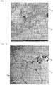
- Fig. 6 Example 1: 5000 times
- Fig. 7 Example 1: 10000 times
- Fig. 8 Comparative Example 1: 5000 times
- Fig. 9 Comparative Example 1: 10000 times
- the plurality of recessed portions 19 are observed to enter the syringe body 11 at the interface between the printing layer 18 and the outer surface 17 of the syringe body 11. Further, as shown in Fig.
- white particles having a size of about several hundred nm or minute white particles observed in the printing layer 18 are barium sulfate, and aggregates of gray particles having a size of about 30 to 50 nm observed in the printing layer 18 are carbon black.
- Example 1 The element distribution of the syringe section of Example 1 was observed using an energy dispersive X-ray spectroscopy. As a result, chlorine was not observed in the syringe body. Since chlorine is derived from chlorinated polypropylene, that is, it is suggested that the outer surface 17 on which the printing layer 18 is printed is not compatible with the printing layer 18. In other words, it can be said that a clear interface is formed between the outer surface 17 on which the printing layer 18 is printed and the printing layer 18.
- the maximum width and the maximum depth thereof were measured with reference to a scale bar.
- the depth d1 and the width d2 (see Fig. 4 ) of the recessed portion 19 in Example 1 were in ranges of 50 to 150 nm and 50 to 200 nm, respectively.
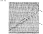
- Fig. 10 and Fig. 11 are TEM images captured in the same manner as described above at a magnification of 2000 times of Example 1 and Comparative Example 1, respectively.
- the thickness d4 of the printing layer 18 at a portion separate from the outer edge 18a of the printing layer 18 by 3 ⁇ m was 1.5 ⁇ m.
- the thickness d4 of the printing layer 18 also at a portion separate from the edge of the printing layer 18 (in Fig. 11 , the edge is present at the further lower left side) by 3 ⁇ m was less than 1 ⁇ m.
- a peeling test was performed with reference to JIS K5600-5-6:1999 (12409:1992). Specifically, CELLOTAPE (registered trademark) CT-18 was strongly bonded by pressure to stride over a printing part along the axis of the syringe body and the edge of the tape was peeled off at once at an angle of 60°. As a result, clear peeling was not recognized in Example 1, but partial peeling-off of the tape was recognized in Comparative Example 1.
Landscapes
- Chemical & Material Sciences (AREA)
- Health & Medical Sciences (AREA)
- Life Sciences & Earth Sciences (AREA)
- Engineering & Computer Science (AREA)
- Chemical Kinetics & Catalysis (AREA)
- Organic Chemistry (AREA)
- Wood Science & Technology (AREA)
- General Health & Medical Sciences (AREA)
- Public Health (AREA)
- Animal Behavior & Ethology (AREA)
- Veterinary Medicine (AREA)
- Hematology (AREA)
- Materials Engineering (AREA)
- Anesthesiology (AREA)
- Heart & Thoracic Surgery (AREA)
- Biomedical Technology (AREA)
- Vascular Medicine (AREA)
- General Chemical & Material Sciences (AREA)
- Polymers & Plastics (AREA)
- Medicinal Chemistry (AREA)
- Pharmacology & Pharmacy (AREA)
- Infusion, Injection, And Reservoir Apparatuses (AREA)
- Medical Preparation Storing Or Oral Administration Devices (AREA)
- Epidemiology (AREA)
Abstract
Description
- The present invention relates to a resin-made syringe, a prefilled syringe, and a method for producing a resin-made syringe.
- A prefillable syringe is a syringe for producing a prefilled syringe filled with a medicine and there are mentioned a glass-made syringe and a resin-made syringe. The resin-made syringe is lighter than the glass-made syringe, is not broken even if dropped, and also has satisfactory dimensional precision, and thus has received attention as a prefillable syringe in recent years. The resin-made syringe is made of a cyclic olefin-based polymer or polyolefin such as polypropylene in order to secure transparency, but since these resins do not have a polar group, such a resin-made syringe is not suitable in a case where graduation for indicating a capacity of a medicine, a medicine name, an expiration date, a logo, a lot number, and the like are directly printed and displayed. Further, when a printing layer printed on a surface of the prefillable syringe is peeled off, there is also considered a concern in that the printing layer is mixed as foreign matters when the medicine is filled. Therefore, as for the resin-made syringe, in order to display graduation for indicating a capacity of a medicine, a medicine name, an expiration date, a logo, and a lot number, a label is pasted (for example, Patent Literature 1). Meanwhile, in a disposable resin-made syringe which is used for suctioning or preparing a medicine or the like in a hospital ward or the like, graduation for indicating an internal capacity is directly printed on an outer surface of a syringe body.
- Patent Literature 1:
JP 2008-272162 A - However, in the prefilled syringe, depending on filled medicines, there is a case where a dosage of a medicine has to be strictly controlled, and a problem arises in that the prefilled syringe lacks precision in graduation with a label. For this reason, a prefillable syringe made of a resin in which graduation or the like is printed on a syringe body is desired. In addition, in the disposable resin-made syringe in which graduation is directly printed, the outer surface of the syringe body is rubbed to wear away the graduation during preparing the medicine, or the like.
- In this regard, an object of the present invention is to provide a resin-made syringe in which a printing layer, such as graduation, which is printed on an outer surface of a syringe body is hardly peeled off, a prefilled syringe, and a method for producing a resin-made syringe.
- The present inventors have conducted intensive studies in order to solve the above-described problem. As a result, the present inventors have found that the above-described problem can be solved by providing a resin-made syringe including a syringe body made of polyolefin and a printing layer printed on at least a part of an outer surface of the syringe body, in which the printing layer has components including chlorinated polypropylene having a degree of chlorination of 15 to 30%, a colorant, and a filler, the outer surface on which the printing layer is printed has a plurality of recessed portions, and
each of the plurality of recessed portions has a depth of 50 nm or more and less than 1 µm and a width of 50 nm or more and less than 1 µm and is filled with at least one kind of the components of the printing layer. - According to the present invention, it is possible to provide a resin-made syringe in which a printing layer printed on a syringe body is hardly peeled off, a prefilled syringe, and a method for producing a resin-made syringe.
-
-
Fig. 1 is a view illustrating a prefilled syringe according to an embodiment of the present invention. -
Fig. 2 is a view illustrating a resin-made syringe (prefillable syringe) according to an embodiment of the present invention. -
Fig. 3 is a cross-sectional view illustrating a state in which a center of the resin-made syringe ofFig. 2 is taken along an axial direction. -
Fig. 4 is an enlarged view of the resin-made syringe and is a view illustrating the vicinity of a printing layer constituting the resin-made syringe. -
Fig. 5 is a flowchart illustrating a method for producing a resin-made syringe according to an embodiment of the present invention. -
Fig. 6 is a TEM image (magnification: 5000 times) of Example 1 constituting an experimental example of the present invention. -
Fig. 7 is a TEM image (magnification: 10000 times) of Example 1. -
Fig. 8 is a TEM image (magnification: 5000 times) of Comparative Example 1. -
Fig. 9 is a TEM image (magnification: 10000 times) of Comparative Example 1. -
Fig. 10 is a TEM image (magnification: 2000 times) of Example 1. -
Fig. 11 is a TEM image (magnification: 2000 times) of Comparative Example 1. - Hereinafter, the present invention will be described. Incidentally, the present invention is not limited only to the following embodiments. Further, in the present specification, the expression "X to Y" indicating a range means "X or more and Y or less". In addition, operations and measurement of physical properties or the like are carried out under the conditions of at room temperature (20 to 25°C)/relative humidity of 40 to 50% RH unless specifically noted.
-
Figs. 1 to 4 are views provided for describing a prefilled syringe 1 or a resin-madesyringe 10 according to an embodiment of the present invention. The prefilled syringe 1 according to an embodiment of the present invention includes, as described in outline with reference toFig. 1 , a resin-madesyringe 10 provided with asyringe body 11, a medicine filled in anaccommodating space 16 of thesyringe body 11, a cap 20 (corresponding to a sealing member) sealing a distal end opening of thesyringe body 11, agasket 30 slidably disposed in theaccommodating space 16 of thesyringe body 11, and aplunger 40. Incidentally, the prefilled syringe is also called a cartridge in a case where the prefilled syringe is used in a state of being integrated into an administration tool for administering a medicine filled in the syringe body. - The resin-made
syringe 10 according to an embodiment of the present invention is, as described in outline with reference toFig. 2 , the resin-madesyringe 10 including thesyringe body 11 made of polyolefin and aprinting layer 18 printed on at least a part of anouter surface 17 of thesyringe body 11. Theprinting layer 18 has components including chlorinated polypropylene having a degree of chlorination of 15 to 30%, a colorant, and a filler as illustrated inFig. 4 , and theouter surface 17 on which theprinting layer 18 is printed has a plurality of recessedportions 19. Each of the plurality ofrecessed portions 19 has a depth d1 of 50 nm or more and less than 1 µm and a width d2 of 50 nm or more and less than 1 µm. Each of the plurality ofrecessed portions 19 is filled with at least one kind of the components of theprinting layer 18. With such a configuration, it is possible to provide the resin-madesyringe 10 in which theprinting layer 18 printed on the syringe body is hardly peeled off. - The resin-made
syringe 10 includes, as illustrated inFigs. 2 and3 , thesyringe body 11 provided with anozzle portion 13, which discharges a liquid such as a medicine, and theprinting layer 18 provided on the outer surface of thesyringe body 11. In this embodiment, theprinting layer 18 is a graduation line indicating an internal capacity of thesyringe body 11. As described above, depending on filled medicines, there is a case where a dosage of a medicine has to be strictly controlled. However, in a case where the graduation line is displayed by a label, by pasting the label itself, the graduation line is deviated from an intended position by about ±1 mm, and thus a dosage of a medicine cannot be strictly controlled. On the other hand, according to an embodiment of the present invention, since theprinting layer 18 is formed directly on theouter surface 17 of thesyringe body 11, deviation of the graduation line from an intended position can be extremely reduced within ±0.1 mm. Therefore, the present invention is suitable for a syringe in which a dosage of a medicine has to be strictly controlled. As a matter of course, theprinting layer 18 may indicate a medicine name, an expiration date, a logo, a lot number, a stop target position or retraction permissible position of thegasket 30, and the like. - The
syringe body 11 includes, as illustrated inFig. 3 , aflange 12 provided on a proximal end of thesyringe body 11, thenozzle portion 13 provided on a distal end of thesyringe body 11, and theaccommodating space 16 formed inside thesyringe body 11. Thesyringe body 11 is, for example, formed in a hollow cylindrical shape. Theflange 12 is formed to protrude from the outer surface of the proximal end portion of thesyringe body 11 to the outside in a radial direction. - The
nozzle portion 13 is provided to protrude in a distal direction. Thenozzle portion 13 includes adischarge portion 14 discharging a liquid such as a medicine and anattachment portion 15 provided to surround the outer periphery of thedischarge portion 14. Thenozzle portion 13 is formed in a double tube shape as illustrated inFig. 3 , and the inner tubular portion corresponds to thedischarge portion 14 and the outer tubular portion corresponds to theattachment portion 15. The distal end of thedischarge portion 14 is opened and forms a distal end opening of thesyringe body 11. - The
attachment portion 15 is a portion to which other medical instruments such as an injection needle not illustrated are attached, and in this embodiment, is integrally formed with thesyringe body 11. As illustrated inFig. 3 , a female screw, which is screwed with a male screw of a mounting portion of other medical instruments such as an injection needle, is provided in the inner wall surface of theattachment portion 15. Incidentally, theattachment portion 15 can be configured as a separate part from other parts in thesyringe body 11. Further, theattachment portion 15 may be omitted. - The
accommodating space 16 corresponds to a cavity part which has a cylindrical shape and is provided radially inside thesyringe body 11. A medicine or the like is filled in thisaccommodating space 16 and a gasket is further inserted so that the prefilled syringe 1 can be prepared. Theaccommodating space 16 is formed almost over theentire syringe body 11 along the axial direction of thesyringe body 11. - The
cap 20 includes a substantially cylindrical grippingportion 21 and a sealingportion 22 sealing the distal end opening of thesyringe body 11 as illustrated inFig. 3 . In this embodiment, the sealingportion 22 is fitted to the outer periphery of thenozzle portion 13 of thesyringe body 11 so that thecap 20 is attached to thesyringe body 11. Further, the grippingportion 21 is disposed at the distal side in relation to theattachment portion 15 of thenozzle portion 13 and is a portion which is gripped by a user when thecap 20 is detached from thesyringe body 11. - Incidentally, the syringe body and the sealing member may have a configuration different from the configurations illustrated in
Figs. 1 to 3 . Specifically, instead of thenozzle portion 13 of thesyringe body 11, a hollow puncture needle fixed to the distal end of thesyringe body 11 is provided. Further, instead of thecap 20 attached to thenozzle portion 13, a sealing member, which is mounted on the distal portion of the syringe body to cover a puncture needle and seals a distal end opening of the puncture needle, may be used. In this case, the distal end opening of the puncture needle forms the distal end opening of the syringe body, and the distal portion of the puncture needle is inserted into the sealing member to seal the distal end opening of the puncture needle. Further, instead of thecap 20, a sealing member, which is fixed to the nozzle portion of the syringe body in a state of not being able to be detached, may be used. In this case, by inserting a medical instrument attached with a needle into the sealing member, the accommodating space and the outside are communicated with each other. - The
syringe body 11 of the present invention is made of polyolefin. Thus, as compared with a glass-made syringe, the syringe made of polyolefin has a technical effect that the syringe is lightweight, is not broken even if dropped, and also has satisfactory dimensional precision - According to an embodiment of the present invention, the polyolefin constituting the
syringe body 11 is a cyclo olefin polymer (COP), a cyclo olefin copolymer (COC), or polypropylene (PP). These polyolefins are desirable as a material forming thesyringe body 11 in terms of transparency, steam sterilization property, and non-adsorbing property of a medicine, but they have a small polarity so that an adhesion force with theprinting layer 18 which is printed tends to be weak. However, since the recessedportion 19 of thesyringe body 11 is filled with at least one kind of the components of theprinting layer 18, theprinting layer 18 printed on thesyringe body 11 is hardly peeled off. - As the cyclo olefin polymer (COP), polymers obtained by ring-opening polymerization and hydrogenation of a cycloolefin-based monomer, which is ring-opening polymerizable, such as norbornene or cyclotetradodecene are suitably used. Further, as the cyclo olefin copolymer (COC), copolymers obtained by using norbornene and olefins such as ethylene as a raw material (addition copolymer of a norbornene-based monomer and α-olefin) and copolymers obtained by using tetracyclododecene and olefins such as ethylene as a raw material are suitably used.
- As the cyclo olefin polymer (COP), for example, ZEONEX Resin manufactured by Zeon Corporation can be used. Further, as the cyclo olefin copolymer (COC), for example, APEL Resin manufactured by Mitsui Chemicals, Inc. can be used.
- The resin-made
syringe 10 of an embodiment of the present invention includes, as illustrated inFig. 2 , thesyringe body 11 made of polyolefin and theprinting layer 18 printed on at least a part of theouter surface 17 of thesyringe body 11. Theprinting layer 18 has components including chlorinated polypropylene having a degree of chlorination of 15 to 30%, a colorant, and a filler as illustrated inFig. 4 , and theouter surface 17 on which theprinting layer 18 is printed has a plurality of recessedportions 19. Each of the plurality of recessedportions 19 has a depth d1 of 50 nm or more and less than 1 µm and a width d2 of 50 nm or more and less than 1 µm. Each of the plurality of recessedportions 19 is filled with at least one kind of the components of theprinting layer 18. With such a configuration, an anchor effect occurs between theprinting layer 18 and theouter surface 17 and an adhesion strength is improved. - According to an embodiment of the present invention, the plurality of recessed
portions 19 on theouter surface 17 on which theprinting layer 18 is printed are configured by only recessed portions having the depth d1 and the width d2 of 50 nm or more and less than 1 µm as illustrated inFig. 4 . Further, according to an embodiment of the present invention, each of the plurality of recessedportions 19 has the depth d1 of 50 to 200 nm and the width d2 of 100 to 500 nm. With such an embodiment, while the mechanical strength of thesyringe body 11 is increased, an anchor effect between theprinting layer 18 and theouter surface 17 can be increased. - Further, the
outer surface 17 of thesyringe body 11 itself is typically flat and smooth without portions considered as the recessedportions 19. Thus, according to an embodiment of the present invention, theouter surface 17 on which theprinting layer 18 is printed has deeper recessedportions 19 than those of theouter surface 17 in a near-field region adjacent to theouter surface 17. Incidentally, the near-field region is an arbitrary region in theouter surface 17, which is adjacent to theprinting layer 18 and has noprinting layer 18 printed thereon, of thesyringe body 11. - According to an embodiment of the present invention, at least one kind of the components of the
printing layer 18 which is filled in each of the plurality of recessedportions 19 is chlorinated polyolefin. By the chlorinated polyolefin having favorable adhesion property with polyolefin that is the syringe body 11 (base material) entering the recessedportion 19, the anchor effect is further increased. - According to an embodiment of the present invention, the
printing layer 18 has an adjacent lamellar structure of chlorinated polypropylene adjacent to theouter surface 17 of thesyringe body 11. Further, a total axial length of the adjacent lamellar structure of chlorinated polypropylene in the cross-section along the axis of thesyringe body 11 is 10% or less of an axial length d5 of theprinting layer 18 illustrated inFig. 4 . According to such an embodiment, since the lamellar structure of chlorinated polypropylene which weakens the adhesion strength between theouter surface 17 of thesyringe body 11 and theprinting layer 18 exists only in a very limited range, the adhesion strength between theouter surface 17 of thesyringe body 11 and theprinting layer 18 can be increased. Incidentally, theprinting layer 18 may have a lamellar structure of chlorinated polypropylene at a position separate from theouter surface 17 of thesyringe body 11, separately from the adjacent lamellar structure. - According to an embodiment of the present invention, the
printing layer 18 has a body region separate from an outer edge of theprinting layer 18 by 3 µm (see a length d3 ofFig. 4 ) or more in a direction along theouter surface 17 of thesyringe body 11 and a thickness d4 of theprinting layer 18 in the body region is 1 to 10 µm. With such a range, it can be said that the ink is printed at an intended position, and precision as indication becomes favorable. Incidentally, the thickness of theprinting layer 18 in the body region is more preferably 2 to 8 µm. - According to an embodiment of the present invention, the
outer surface 17 on which theprinting layer 18 is printed is not compatible with theprinting layer 18. By theouter surface 17 on which theprinting layer 18 is printed being not compatible with theprinting layer 18, the nature and physical property of the material of thesyringe body 11 are not changed. Therefore, it is suppressed that a substance derived from the material of thesyringe body 11 which is changed by compatibilization is melted in the medicine in thesyringe body 11, or the strength of thesyringe body 11 is decreased so that thesyringe body 11 is easily broken or does not withstand high-pressure steam sterilization. Thus, according to an embodiment of the present invention, a clear interface is present between theouter surface 17 on which theprinting layer 18 is printed and theprinting layer 18. - According to an embodiment of the present invention, the
printing layer 18 is formed by applying an ink to theouter surface 17 of thesyringe body 11 made of polyolefin. Further, the ink has components including a volatile solvent, which contains a dissolving component dissolving the polyolefin, chlorinated polypropylene having a degree of chlorination of 15 to 30%, a colorant, and a filler. Such an ink is also referred to as an ink of the present invention (or simply referred to as "ink") in the present specification. - The ink of the present invention contains chlorinated polypropylene. Further, the degree of chlorination of the chlorinated polypropylene is 15 to 30%. In an embodiment of the present invention, the degree of chlorination is preferably 20 to 29%, more preferably 23 to 28%, and preferably 25 to 27%. With such a range, the desired effects by the present invention can be efficiently provided. In addition, in an embodiment of the present invention, the degree of chlorination is 8.3 to 3.6% with respect to H in a propylene unit [-CH(CH3)-CH2-] in the chlorinated polypropylene. With such a range, it is possible to form the
printing layer 18 which is more hardly peeled off. - According to an embodiment of the present invention, the chlorinated polypropylene is contained in preferably 10 to 35% by mass, more preferably 13 to 30% by mass, and further preferably 16 to 30% by mass in the ink. With such a range, it is possible to form the
printing layer 18 which is more hardly peeled off. - The chlorinated polypropylene which may be used in the present invention may be synthesized with reference to a conventional known method, or if there is a commercially available product, the commercially available product may be purchased and prepared as the chlorinated polypropylene.
- The ink of the present invention contains a colorant. The color of the colorant is not particularly limited, but a black ink is used in the printing layer in many cases. As the black colorant which may be used in the ink of the present invention, for example, carbon black such as furnace black, channel black, acetylene black, thermal black, or lampblack, a magnetic powder such as magnetite or ferrite, and the like are suitable. As for colorants of other colors, known colorants usable in the relevant field can be applied.
- According to an embodiment of the present invention, the colorant is contained in preferably 3 to 15% by mass and more preferably 5 to 10% by mass in the ink. With such a range, it is possible to form the
printing layer 18 which is hardly peeled off and easily visible. - The ink of the present invention contains a filler. By containing a filler, dispersibility of the ink is improved and glossiness can be controlled. Types of the filler are also not particularly limited, but the ink may contain, for example, an inorganic filler such as barium sulfate, talc, calcium carbonate, zinc carbonate, Wollastonite, silica, alumina, magnesium oxide, calcium silicate, sodium aluminate, calcium aluminate, sodium aluminosilicate, magnesium silicate, zinc oxide, antimony trioxide, zeolite, hydrotalcite, metallic fiber, metal whisker, ceramic whisker, potassium titanate, boron nitride, or carbon fiber; or an organic filler such as a naturally derived polymer such as starch, cellulose fine particles, or wood powder or modified products thereof. In particular, barium sulfate may function as an extender pigment and may also function as a stabilizer for preventing a dehydrochlorination reaction of chlorinated polypropylene.
- According to an embodiment of the present invention, the filler is contained in preferably 15 to 60% by mass, more preferably 25 to 45% by mass, and further preferably 25 to 35% by mass in the ink. With such a range, it is possible to form the
printing layer 18 which is hardly peeled off and has less color unevenness. - The ink of the present invention contains a volatile solvent which contains a dissolving component dissolving the polyolefin.
- According to an embodiment of the present invention, as the volatile solvent, for example, toluene, trimethylbenzene, cyclohexane, tetrahydrofuran, and the like are suitable. According to such an embodiment, the chlorinated polypropylene can be efficiently dissolved in the volatile solvent. Further, by combining toluene and trimethylbenzene, solubility of the chlorinated polypropylene can be further increased. Incidentally, trimethylbenzene is at least one kind of 1,2,4-trimethylbenzene, 1,2,3-trimethylbenzene, and 1,3,5-trimethylbenzene.
- The volatile solvent contains a dissolving component dissolving the polyolefin. According to an embodiment of the present invention, the dissolving component is an aromatic hydrocarbon having a benzene ring structure and a hydrocarbon side chain and the number of carbon atoms of the hydrocarbon side chain is 2 or more. According to an embodiment of the present invention, the number of carbon atoms is preferably 2 to 10 and more preferably 2 to 5. With such a range, when the ink is applied to the
outer surface 17 of thesyringe body 11, the recessedportions 19 can be efficiently formed on theouter surface 17 of thesyringe body 11. According to an embodiment of the present invention, as the dissolving component, p-cymene, ethylbenzene, and cumene are suitable, and particularly, p-cymene is preferred. - According to an embodiment of the present invention, the volatile solvent is contained in preferably 15 to 40% by mass, more preferably 20 to 35% by mass, and further preferably 20 to 30% by mass (in the case of containing two or more kinds of volatile solvent, the total amount thereof) in the ink. Further, according to an embodiment of the present invention, the ink preferably contains 15 to 40% by mass of toluene and more preferably contains 20 to 30% by mass of toluene. By containing toluene in such a range, the volatilization rate of the solvent when the ink is applied to the
outer surface 17 of thesyringe body 11 becomes appropriate, and as a result, it is suppressed that the lamellar structure of the chlorinated polypropylene is excessively formed in the printing layer. Further, a technical effect that theprinting layer 18 can be formed without thesyringe body 11 being substantially dissolved by toluene is obtained. - Further, according to an embodiment of the present invention, the
printing layer 18 preferably contains 14 to 50% by mass of chlorinated polypropylene having a degree of chlorination of 15 to 30%, and more preferably contains 18 to 43% by mass of chlorinated polypropylene having a degree of chlorination of 15 to 30%. Further, according to an embodiment of the present invention, theprinting layer 18 preferably contains 4 to 22% by mass of a colorant, and more preferably contains 7 to 14% by mass of a colorant. Further, according to an embodiment of the present invention, theprinting layer 18 preferably contains 21 to 86% by mass of a filler, and more preferably contains 35 to 64% by mass of a filler. - According to an embodiment of the present invention, the
outer surface 17 of thesyringe body 11 is subjected to a sterilization treatment by an autoclave. According to the present invention, since the recessedportion 19 of thesyringe body 11 is filled with at least one kind of the components of theprinting layer 18, a technical effect that the peeling-off of theprinting layer 18 is suppressed even when subjected to autoclave sterilization is obtained. Incidentally, the autoclave method will be described later. - The resin-made
syringe 10 is a syringe before a medicine is filled. After the medicine is filled, by providing thecap 20 sealing the distal end opening of thesyringe body 11 and thegasket 30 slidably disposed in theaccommodating space 16 of thesyringe body 11, the resin-madesyringe 10 becomes the prefilled syringe 1. Thus, the prefilled syringe 1 includes the resin-madesyringe 10, a medicine filled in thesyringe body 11 of the resin-madesyringe 10, thecap 20 sealing the distal end opening of thesyringe body 11, and thegasket 30 slidably disposed in thesyringe body 11. With such a prefilled syringe 1, since a label is not used, a case where the label is peeled off does not occur, and a dosage of a medicine can be strictly controlled. - Further, in an embodiment of the present invention, the medicine is filled in the
syringe body 11 in an amount more than a dose, and theprinting layer 18 is a graduation line printed at a position where the internal capacity of thesyringe body 11 coincides with the dose of the medicine. Since theprinting layer 18 is formed directly on theouter surface 17 of thesyringe body 11, deviation of the graduation line from an intended position is extremely reduced. Therefore, when the gasket is moved forward to the graduation line in order to make the amount of the medicine in thesyringe body 11 coincide with the dose, the amount of the medicine in thesyringe body 11 can be reliably made to coincide with the dose. Particularly, in the case of administration of a small dose of a medicine, that is, the dose of 0.5 mL or less, in order to more reliably make the amount of the medicine in thesyringe body 11 when the gasket is moved forward to the graduation line coincide with the dose, accuracy of the position of the graduation line is extremely important. - Next, a method for producing the resin-made
syringe 10 according to this embodiment will be described.Fig. 5 is a flowchart illustrating a method for producing a resin-made syringe according to an embodiment of the present invention. In the method, thesyringe body 11 made of polyolefin is prepared as illustrated inFig. 5 . Further, an ink having components including a volatile solvent, which contains a dissolving component dissolving the polyolefin, chlorinated polypropylene having a degree of chlorination of 15 to 30%, a colorant, and a filler is prepared (preparation step (ST1)). Next, the ink is applied to at least a part of theouter surface 17 of the syringe body 11 (application step (ST2)). Next, the applied ink is dried to form theprinting layer 18 having components including the chlorinated polypropylene, the colorant, and the filler on the outer surface 17 (drying step (ST3)). In the application step, by dissolving at least a part of theouter surface 17 by the dissolving component, the plurality of recessedportions 19 are formed on theouter surface 17 and each of the plurality of recessedportions 19 is filled with at least one kind of components of the ink. Further, by drying the ink, each of the plurality of recessedportions 19 is filled with at least one kind of the components of theprinting layer 18. - In the method for producing the resin-made
syringe 10 of the present invention, thesyringe body 11 made of polyolefin is prepared. Further, the method includes a preparation step of preparing an ink having components including a volatile solvent, which contains a dissolving component dissolving the polyolefin, chlorinated polypropylene having a degree of chlorination of 15 to 30%, a colorant, and a filler (see ST1 ofFig. 5 ). - As for the
syringe body 11 made of polyolefin, a commercially available product can be purchased and prepared as described above. The ink can be prepared by appropriately mixing the components constituting the ink described above. - The method for producing a resin-made syringe of the present invention includes an application step of applying the ink to at least a part of the
outer surface 17 of the syringe body 11 (see ST2 ofFig. 5 ). Further, the method for producing a resin-made syringe of the present invention includes a drying step of forming theprinting layer 18 having components including the colorant and the filler (see ST3 ofFig. 5 ). - The application step is sufficient that an amount enough to print the
printing layer 18 can be applied, and the application amount can be appropriately set according to a printing area of theprinting layer 18. In a case where theprinting layer 18 is graduation indicating the internal capacity of thesyringe body 11, it is preferable to apply the ink such that the ink becomes a linear graduation line along the circumferential direction of thesyringe body 11. The thickness of the graduation line is preferably 0.1 to 1.0 mm and more preferably 0.3 to 0.6 mm. Incidentally, only one graduation line may be provided as a gauge line indicating a dose of a medicine on theouter surface 17 of thesyringe body 11. Further, a plurality of graduation lines may be intermittently provided to indicate a plurality of internal capacities of thesyringe body 11. Further, a specific application method in the application step is also not particularly limited, and for example, it is suitable to use screen printing, offset printing, and the like. - Further, the dying condition in the drying step is also not particularly limited and is sufficient to be a condition that the volatile solvent in the ink is substantially volatilized, but the drying step is preferably performed, for example, at 60°C for 30 minutes. In addition, the ink may be dried using a halogen lamp or the like at a higher temperature in a short period of time.
- In the method for producing the resin-made
syringe 10 of the present invention, in the application step, by dissolving at least a part of theouter surface 17 by the dissolving component, the plurality of recessedportions 19 are formed on theouter surface 17 and each of the plurality of recessedportions 19 is filled with at least one kind of components of the ink. Further, by drying the ink, each of the plurality of recessedportions 19 is filled with at least one kind of the components of theprinting layer 18. In this way, the resin-madesyringe 10 in which theprinting layer 18 is printed on at least a part of theouter surface 17 of thesyringe body 11 made of polyolefin as illustrated inFigs. 2 to 4 can be produced. Theprinting layer 18 in the resin-madesyringe 10 contains components including chlorinated polypropylene having a degree of chlorination of 15 to 30%, a colorant, and a filler. Theouter surface 17 on which theprinting layer 18 is printed has the plurality of recessedportions 19. Each of the plurality of recessedportions 19 has a depth d1 of 50 nm or more and less than 1 µm and a width d2 of 50 nm or more and less than 1 µm. Each of the plurality of recessedportions 19 is filled with at least one kind of the components of theprinting layer 18. - Further, in an embodiment of the present invention, a method for producing the resin-made
syringe 10 is provided. In the method, thesyringe body 11 made of polyolefin is prepared, and an ink having components including a volatile solvent, which contains a dissolving component dissolving the polyolefin, chlorinated polypropylene having a degree of chlorination of 15 to 30%, a colorant, and a filler is prepared. Further, the ink is applied to theouter surface 17 of thesyringe body 11. Further, the applied ink is dried to form theprinting layer 18 having components including chlorinated polypropylene, a colorant, and a filler on theouter surface 17. In the application step, by dissolving at least a part of theouter surface 17 by the dissolving component, the plurality of recessedportions 19 are formed on theouter surface 17. Further, each of the plurality of recessedportions 19 is filled with at least one kind of the components of the ink. Further, in the drying of the ink, by volatilizing the volatile solvent in the ink components, each of the plurality of recessedportions 19 is filled with at least one kind of the components of theprinting layer 18. - In an embodiment of the present invention, an empty syringe for filling a medicine such as a prefillable syringe has to be in a clean and antiseptic state until the medicine is filled, and thus the syringe may be subjected to a sterilization treatment in a state of being accommodated in a packaging material in advance. Therefore, according to an embodiment of the present invention, the method includes a sterilization step of subjecting the
syringe body 11 to autoclave sterilization (see ST4 ofFig. 5 ) . - According to an embodiment of the present invention, the autoclave sterilization is carried out at preferably 121 to 125°C and more preferably 121 to 123°C. Further, according to an embodiment of the present invention, the autoclave sterilization is performed for preferably 20 to 120 minutes, more preferably 20 to 90 minutes, and further preferably 20 to 60 minutes.
- Hereinafter, representative embodiments of the present invention will be described and the present invention will be further described; however, as a matter of course, the present invention is not limited to these embodiments. Incidentally, "part(s)" represents "part(s) by mass" and "%" represents "% by mass" in Examples unless specifically noted. In addition, operations and measurement of physical properties or the like were carried out under the conditions of at room temperature (20 to 25°C)/relative humidity of 40 to 50% RH unless specifically noted.
- An ink was applied to one place of the
outer surface 17 of thesyringe body 11 of a cyclo olefin polymer (ZEONEX (registered trademark) manufactured by Zeon Corporation) such that the ink became a linear graduation line annularly continued in a circumferential direction of thesyringe body 11. Specifically, while thesyringe body 11 was rotated about the axis, an ink prepared by the following method was applied using a screen printer for a curved face (SK-250-S type) manufactured by Shinei Kogyo Co., Ltd. Thereafter, the ink was dried at 60°C for 30 minutes to produce the resin-madesyringe 10 having a gauge line indicating a dose of a medicine. - An ink having components including
- 26 parts of toluene,
- 6.5 parts of trimethylbenzene,
- 2 parts of naphthalene,
- 8 parts of carbon black,
- 20 parts of chlorinated polypropylene having a degree of chlorination of 26% (HARDLEN (registered trademark) (13-LLP) manufactured by TOYOBO CO., LTD.),
- 0.5 parts of p-cymene, and 37 parts of barium sulfate
- The resin-made
syringe 10 was produced in the same manner as in Example 1, except that preparation of an ink was performed as follows. - An ink having components including
- 29 parts of toluene,
- 6.5 parts of trimethylbenzene,
- 1.5 parts of naphthalene,
- 2 parts of methanol,
- 0.5 parts of isobutanol,
- 8 parts of carbon black,
- 20 parts of chlorinated polyethylene having a degree of chlorination of 22 to 25% (ELASLEN (registered trademark) (grade: 252B) manufactured by Showa Denko K.K.), and
- 32.5 parts of barium sulfate
- The resin-made
syringes 10 having theprinting layer 18 printed thereon, which were produced in Example 1 and Comparative Example 1, were coated with platinum and embedded in resin by Luft method. Thereafter, ultrathin sections (syringe sections) were produced along the axis of thesyringe body 11. - The outer surfaces of the syringe sections were observed using a transmission electron microscope (TEM) in a bright field (magnification: 5000 times, 10000 times) The observed TEM images are shown in
Fig. 6 (Example 1: 5000 times),Fig. 7 (Example 1: 10000 times),Fig. 8 (Comparative Example 1: 5000 times), andFig. 9 (Comparative Example 1: 10000 times). InFigs. 6 and7 , the plurality of recessedportions 19 are observed to enter thesyringe body 11 at the interface between theprinting layer 18 and theouter surface 17 of thesyringe body 11. Further, as shown inFig. 7 , it is found that at least one kind of the ink components (particularly, chlorinated polyolefin shown in pale black) is filled in the recessedportion 19. On the other hand, as shown inFigs. 8 and9 , in Comparative Example 1, there was no place in which the recessedportion 19 can be recognized at the interface between theprinting layer 18 and theouter surface 17 of thesyringe body 11. The reason for this is considered that the ink used in Comparative Example 1 does not contain a dissolving component dissolving polyolefin. - Incidentally, white particles having a size of about several hundred nm or minute white particles observed in the
printing layer 18 are barium sulfate, and aggregates of gray particles having a size of about 30 to 50 nm observed in theprinting layer 18 are carbon black. - The element distribution of the syringe section of Example 1 was observed using an energy dispersive X-ray spectroscopy. As a result, chlorine was not observed in the syringe body. Since chlorine is derived from chlorinated polypropylene, that is, it is suggested that the
outer surface 17 on which theprinting layer 18 is printed is not compatible with theprinting layer 18. In other words, it can be said that a clear interface is formed between theouter surface 17 on which theprinting layer 18 is printed and theprinting layer 18. - Regarding all of cases where the recessed
portion 19 can be clearly recognized in images captured at 10 places randomly selected in syringe sections of Example 1, the maximum width and the maximum depth thereof were measured with reference to a scale bar. As a result, the depth d1 and the width d2 (seeFig. 4 ) of the recessedportion 19 in Example 1 were in ranges of 50 to 150 nm and 50 to 200 nm, respectively. -
Fig. 10 andFig. 11 are TEM images captured in the same manner as described above at a magnification of 2000 times of Example 1 and Comparative Example 1, respectively. InFigs. 4 and10 , in Example 1, the thickness d4 of theprinting layer 18 at a portion separate from theouter edge 18a of theprinting layer 18 by 3 µm (see the length d3 ofFig. 4 ) was 1.5 µm. Further, inFig. 11 , in Comparative Example 1, the thickness d4 of theprinting layer 18 also at a portion separate from the edge of the printing layer 18 (inFig. 11 , the edge is present at the further lower left side) by 3 µm was less than 1 µm. - A peeling test was performed with reference to JIS K5600-5-6:1999 (12409:1992). Specifically, CELLOTAPE (registered trademark) CT-18 was strongly bonded by pressure to stride over a printing part along the axis of the syringe body and the edge of the tape was peeled off at once at an angle of 60°. As a result, clear peeling was not recognized in Example 1, but partial peeling-off of the tape was recognized in Comparative Example 1.
- This application is based on Japanese Patent Application No.
2017-131526, filed on July 4, 2017 -
- 1 PREFILLED SYRINGE
- 10 RESIN-MADE SYRINGE
- 11 SYRINGE BODY
- 17 OUTER SURFACE
- 18 PRINTING LAYER
- 20 CAP (SEALING MEMBER)
- 30 GASKET
- 40 PLUNGER
- d1 DEPTH (OF RECESSED PORTION)
- d2 WIDTH (OF RECESSED PORTION)
- d3 LENGTH (OF PRINTING LAYER FROM OUTER EDGE IN AXIAL DIRECTION)
- d4 THICKNESS (OF PRINTING LAYER AT POSITION SEPARATE FROM OUTER EDGE BY LENGTH d3)
- d5 AXIAL LENGTH (OF PRINTING LAYER)
Claims (15)
- A resin-made syringe comprising a syringe body made of polyolefin and a printing layer printed on at least a part of an outer surface of the syringe body,
wherein the printing layer has components including chlorinated polypropylene having a degree of chlorination of 15 to 30%, a colorant, and a filler,
the outer surface on which the printing layer is printed has a plurality of recessed portions, and
each of the plurality of recessed portions has a depth of 50 nm or more and less than 1 µm and a width of 50 nm or more and less than 1 µm and is filled with at least one kind of the components of the printing layer. - The resin-made syringe according to claim 1, wherein the at least one kind of the components of the printing layer filled in each of the plurality of recessed portions is chlorinated polyolefin.
- The resin-made syringe according to claim 1 or 2, wherein the polyolefin is a cyclo olefin polymer, a cyclo olefin copolymer, or polypropylene.
- The resin-made syringe according to any one of claims 1 to 3, wherein each of the plurality of recessed portions has a depth of 50 to 200 nm and a width of 100 to 500 nm.
- The resin-made syringe according to any one of claims 1 to 4, wherein the printing layer has an adjacent lamellar structure of chlorinated polypropylene adjacent to the outer surface of the syringe body and a total axial length of the adjacent lamellar structure of chlorinated polypropylene in the cross-section along an axis of the syringe body is 10% or less of an axial length of the printing layer.
- The resin-made syringe according to any one of claims 1 to 5, wherein the printing layer has a body region separate from an outer edge of the printing layer by 3 µm or more in a direction along the outer surface of the syringe body and a thickness of the printing layer in the body region is 1 to 10 µm.
- The resin-made syringe according to any one of claims 1 to 6, wherein the outer surface on which the printing layer is printed is not compatible with the printing layer.
- The resin-made syringe according to any one of claims 1 to 7, wherein the printing layer is a graduation line indicating an internal capacity of the syringe body.
- The resin-made syringe according to any one of claims 1 to 8, wherein the resin-made syringe is already subjected to autoclave sterilization.
- A prefilled syringe comprising:the resin-made syringe according to any one of claims 1 to 9;a medicine filled in the syringe body of the resin-made syringe;a sealing member sealing a distal end opening of the syringe body; anda gasket slidably disposed in the syringe body.
- The prefilled syringe according to claim 10, wherein the medicine is filled in the syringe body in an amount more than a dose, and
the printing layer is a graduation line printed at a position where the internal capacity of the syringe body coincides with the dose of the medicine. - A method for producing a resin-made syringe, the method comprising:a preparation step of preparing a syringe body made of polyolefin and further preparing an ink having components including a volatile solvent, which contains a dissolving component dissolving the polyolefin, chlorinated polypropylene having a degree of chlorination of 15 to 30%, a colorant, and a filler;an application step of applying the ink to at least a part of the outer surface of the syringe body; anda drying step of drying the applied ink to form a printing layer, which has the components including the chlorinated polypropylene, the colorant, and the filler, on the outer surface,wherein in the application step, at least a part of the outer surface is dissolved by the dissolving component to form a plurality of recessed portions on the outer surface, each of the plurality of recessed portions is filled with at least one kind of the components of the ink, and each of the plurality of recessed portions is filled with at least one kind of the components of the printing layer by drying the ink.
- The method for producing a resin-made syringe according to claim 12, wherein the dissolving component is an aromatic hydrocarbon having a benzene ring structure and a hydrocarbon side chain and the number of carbon atoms of the hydrocarbon side chain is 2 or more.
- The method for producing a resin-made syringe according to claim 12 or 13, wherein the ink contains 15 to 40% by mass of toluene.
- The method for producing a resin-made syringe according to any one of claims 12 to 14, further comprising a sterilization step of subjecting the syringe body to autoclave sterilization.
Applications Claiming Priority (2)
| Application Number | Priority Date | Filing Date | Title |
|---|---|---|---|
| JP2017131526 | 2017-07-04 | ||
| PCT/JP2018/025353 WO2019009326A1 (en) | 2017-07-04 | 2018-07-04 | Syringe formed from resin, pre-filled syringe, and method for producing syringe formed from resin |
Publications (4)
| Publication Number | Publication Date |
|---|---|
| EP3650063A1 true EP3650063A1 (en) | 2020-05-13 |
| EP3650063A4 EP3650063A4 (en) | 2020-12-23 |
| EP3650063B1 EP3650063B1 (en) | 2024-01-24 |
| EP3650063C0 EP3650063C0 (en) | 2024-01-24 |
Family
ID=64950102
Family Applications (1)
| Application Number | Title | Priority Date | Filing Date |
|---|---|---|---|
| EP18827619.0A Active EP3650063B1 (en) | 2017-07-04 | 2018-07-04 | Syringe formed from resin, pre-filled syringe, and method for producing syringe formed from resin |
Country Status (6)
| Country | Link |
|---|---|
| US (3) | US20200139051A1 (en) |
| EP (1) | EP3650063B1 (en) |
| JP (2) | JP7051850B2 (en) |
| CN (2) | CN110831644A (en) |
| AU (1) | AU2018295781B2 (en) |
| WO (1) | WO2019009326A1 (en) |
Families Citing this family (1)
| Publication number | Priority date | Publication date | Assignee | Title |
|---|---|---|---|---|
| WO2023073864A1 (en) * | 2021-10-28 | 2023-05-04 | 学校法人君が淵学園 | Method for producing high purity polyethylene or polypropylene |
Family Cites Families (26)
| Publication number | Priority date | Publication date | Assignee | Title |
|---|---|---|---|---|
| US4275729A (en) * | 1979-10-29 | 1981-06-30 | Jules Silver | Adjustable dosage syringe |
| JPS5867736A (en) * | 1981-10-19 | 1983-04-22 | Showa Denko Kk | Polyolefin composition |
| US4724508A (en) * | 1985-12-18 | 1988-02-09 | Becton, Dickinson And Company | Method and apparatus for the continuous corona discharge treatment of the surface of formed articles |
| JP2634197B2 (en) * | 1988-07-05 | 1997-07-23 | 株式会社トップ | Scaled fluororesin indwelling catheter and method for producing the same |
| NZ244576A (en) * | 1989-02-08 | 1994-11-25 | Becton Dickinson Co | Syringe barrel with contrast band opposite indicia to improve readability |
| JP2596884B2 (en) * | 1993-04-27 | 1997-04-02 | 日本製紙株式会社 | Binder resin solution composition with good low-temperature fluidity |
| JPH09314793A (en) * | 1996-05-31 | 1997-12-09 | Dainippon Printing Co Ltd | Makeup sheet |
| CA2279737C (en) * | 1998-08-06 | 2004-04-27 | Naoya Haruta | Decorative film for use in platics molding, process for preparing the same and injection-molded part by use of the same |
| US6966897B2 (en) * | 2000-09-22 | 2005-11-22 | Arte Corporation | Combined container-syringe and assembly method of the same |
| US20040186437A1 (en) * | 2003-03-20 | 2004-09-23 | Frenette Claude E. | Content-coded medical syringe, syringe set and syringe content identification method |
| CA2551698C (en) * | 2004-01-07 | 2016-05-24 | Smiths Medical Asd, Inc. | Needle protection device with gauge specific color coding and method for manufacturing thereof |
| JP2006057056A (en) * | 2004-08-23 | 2006-03-02 | Dainichiseika Color & Chem Mfg Co Ltd | Gravure ink for polypropylene film |
| JP4967429B2 (en) * | 2006-04-10 | 2012-07-04 | 大日本印刷株式会社 | Manufacturing method of printed matter |
| ES2488667T3 (en) * | 2007-01-22 | 2014-08-28 | Teva Pharmaceutical Industries Ltd | Syringe that has a syringe label |
| JP2008272162A (en) | 2007-04-27 | 2008-11-13 | Ajinomoto Co Inc | Syringe label and syringe |
| US8062254B2 (en) | 2008-01-08 | 2011-11-22 | MacLean, LLC | Spring driven adjustable oral syringe |
| CN201969136U (en) * | 2011-01-26 | 2011-09-14 | 成都市新津事丰医疗器械有限公司 | Disposable syringe screen mesh jacket |
| JP6166564B2 (en) * | 2013-03-22 | 2017-07-19 | 日本製紙株式会社 | Chlorinated polyolefin resin composition |
| JP6291318B2 (en) * | 2014-03-31 | 2018-03-14 | テルモ株式会社 | Rocuronium bromide injection filled prefilled syringe |
| RU2702748C2 (en) | 2014-05-12 | 2019-10-11 | Формикон Аг | Pre-filled plastic syringe containing vegf antagonist |
| JP2016149193A (en) | 2015-02-10 | 2016-08-18 | 新興プラスチックス株式会社 | Method of manufacturing light guide plate and light guide plate manufactured by same method |
| CN105419090A (en) * | 2015-12-14 | 2016-03-23 | 山东凯利医疗器械有限公司 | Polypropylene material for disposable syringe and preparation method thereof |
| JP2017131526A (en) | 2016-01-29 | 2017-08-03 | 東芝ライフスタイル株式会社 | Autonomously travelling vacuum cleaner |
| US10076881B2 (en) * | 2016-09-08 | 2018-09-18 | Xerox Corporation | System and method for forming a base layer with interfacial anchoring to stabilize a three-dimensional object during additive manufacturing |
| CN110191805A (en) * | 2017-01-30 | 2019-08-30 | 优泊公司 | Thermoplastic resin film and adhesive label |
| AT521806A2 (en) | 2017-06-30 | 2020-05-15 | Ccl Secure Pty Ltd | Process for the production of micro picture elements on a substrate |
-
2018
- 2018-07-04 CN CN201880044543.XA patent/CN110831644A/en active Pending
- 2018-07-04 CN CN202511007841.XA patent/CN120771389A/en active Pending
- 2018-07-04 AU AU2018295781A patent/AU2018295781B2/en active Active
- 2018-07-04 JP JP2019527742A patent/JP7051850B2/en active Active
- 2018-07-04 EP EP18827619.0A patent/EP3650063B1/en active Active
- 2018-07-04 WO PCT/JP2018/025353 patent/WO2019009326A1/en not_active Ceased
-
2020
- 2020-01-03 US US16/734,089 patent/US20200139051A1/en not_active Abandoned
-
2022
- 2022-03-30 JP JP2022057062A patent/JP7291828B2/en active Active
-
2023
- 2023-02-28 US US18/115,706 patent/US12383679B2/en active Active
- 2023-05-16 US US18/198,193 patent/US11975178B2/en active Active
Also Published As
| Publication number | Publication date |
|---|---|
| US20200139051A1 (en) | 2020-05-07 |
| US20230285679A1 (en) | 2023-09-14 |
| EP3650063B1 (en) | 2024-01-24 |
| JPWO2019009326A1 (en) | 2020-05-07 |
| AU2018295781B2 (en) | 2020-12-24 |
| US20230201465A1 (en) | 2023-06-29 |
| US12383679B2 (en) | 2025-08-12 |
| AU2018295781A1 (en) | 2020-01-23 |
| EP3650063C0 (en) | 2024-01-24 |
| WO2019009326A1 (en) | 2019-01-10 |
| JP7051850B2 (en) | 2022-04-11 |
| CN120771389A (en) | 2025-10-14 |
| EP3650063A4 (en) | 2020-12-23 |
| US11975178B2 (en) | 2024-05-07 |
| JP7291828B2 (en) | 2023-06-15 |
| JP2022082657A (en) | 2022-06-02 |
| CN110831644A (en) | 2020-02-21 |
Similar Documents
| Publication | Publication Date | Title |
|---|---|---|
| US10960139B2 (en) | Syringe assembly having a rotatably advanceable plunger rod | |
| US11975178B2 (en) | Resin syringe, prefilled syringe, and method for producing resin syringe | |
| JP6411097B2 (en) | Prefilled syringe | |
| AU623730B2 (en) | Syringe having graphic visualization features | |
| EP2543405A1 (en) | Syringe | |
| EP2832391A1 (en) | Syringe | |
| US6981618B2 (en) | Container assembly for a substance to be applied | |
| JP2015512760A (en) | Self-injection device with indicator indicating proper coupling of components | |
| AU2008261631A1 (en) | Syringe with disabling mechanism | |
| US9308328B2 (en) | Plunger rod and syringe | |
| EP3453417B1 (en) | Syringe barrel and pre-filled syringe | |
| WO2011125475A1 (en) | Syringe | |
| US20200164324A1 (en) | A storage, mixing and dispensing device | |
| EP3127568B1 (en) | Pre-filled syringe filled with rocuronium bromide injection solution | |
| US20210353866A1 (en) | Colored Seal System | |
| JP5444835B2 (en) | Prefilled syringe and prefilled syringe | |
| JP2003180711A (en) | Container | |
| US10098812B2 (en) | Multi-component container | |
| US20230074659A1 (en) | Detection System for Syringe Assembly |
Legal Events
| Date | Code | Title | Description |
|---|---|---|---|
| STAA | Information on the status of an ep patent application or granted ep patent |
Free format text: STATUS: THE INTERNATIONAL PUBLICATION HAS BEEN MADE |
|
| PUAI | Public reference made under article 153(3) epc to a published international application that has entered the european phase |
Free format text: ORIGINAL CODE: 0009012 |
|
| STAA | Information on the status of an ep patent application or granted ep patent |
Free format text: STATUS: REQUEST FOR EXAMINATION WAS MADE |
|
| 17P | Request for examination filed |
Effective date: 20191220 |
|
| AK | Designated contracting states |
Kind code of ref document: A1 Designated state(s): AL AT BE BG CH CY CZ DE DK EE ES FI FR GB GR HR HU IE IS IT LI LT LU LV MC MK MT NL NO PL PT RO RS SE SI SK SM TR |
|
| AX | Request for extension of the european patent |
Extension state: BA ME |
|
| DAV | Request for validation of the european patent (deleted) | ||
| DAX | Request for extension of the european patent (deleted) | ||
| A4 | Supplementary search report drawn up and despatched |
Effective date: 20201125 |
|
| RIC1 | Information provided on ipc code assigned before grant |
Ipc: A61M 5/28 20060101ALI20201119BHEP Ipc: A61M 5/24 20060101ALI20201119BHEP Ipc: A61J 1/05 20060101ALI20201119BHEP Ipc: A61M 5/31 20060101AFI20201119BHEP |
|
| GRAP | Despatch of communication of intention to grant a patent |
Free format text: ORIGINAL CODE: EPIDOSNIGR1 |
|
| STAA | Information on the status of an ep patent application or granted ep patent |
Free format text: STATUS: GRANT OF PATENT IS INTENDED |
|
| INTG | Intention to grant announced |
Effective date: 20230831 |
|
| GRAS | Grant fee paid |
Free format text: ORIGINAL CODE: EPIDOSNIGR3 |
|
| GRAA | (expected) grant |
Free format text: ORIGINAL CODE: 0009210 |
|
| STAA | Information on the status of an ep patent application or granted ep patent |
Free format text: STATUS: THE PATENT HAS BEEN GRANTED |
|
| AK | Designated contracting states |
Kind code of ref document: B1 Designated state(s): AL AT BE BG CH CY CZ DE DK EE ES FI FR GB GR HR HU IE IS IT LI LT LU LV MC MK MT NL NO PL PT RO RS SE SI SK SM TR |
|
| REG | Reference to a national code |
Ref country code: GB Ref legal event code: FG4D |
|
| REG | Reference to a national code |
Ref country code: CH Ref legal event code: EP |
|
| REG | Reference to a national code |
Ref country code: IE Ref legal event code: FG4D |
|
| REG | Reference to a national code |
Ref country code: DE Ref legal event code: R096 Ref document number: 602018064572 Country of ref document: DE |
|
| U01 | Request for unitary effect filed |
Effective date: 20240223 |
|
| U07 | Unitary effect registered |
Designated state(s): AT BE BG DE DK EE FI FR IT LT LU LV MT NL PT SE SI Effective date: 20240301 |
|
| REG | Reference to a national code |
Ref country code: LT Ref legal event code: MG9D |
|
| PG25 | Lapsed in a contracting state [announced via postgrant information from national office to epo] |
Ref country code: IS Free format text: LAPSE BECAUSE OF FAILURE TO SUBMIT A TRANSLATION OF THE DESCRIPTION OR TO PAY THE FEE WITHIN THE PRESCRIBED TIME-LIMIT Effective date: 20240524 |
|
| U20 | Renewal fee for the european patent with unitary effect paid |
Year of fee payment: 7 Effective date: 20240605 |
|
| PG25 | Lapsed in a contracting state [announced via postgrant information from national office to epo] |
Ref country code: GR Free format text: LAPSE BECAUSE OF FAILURE TO SUBMIT A TRANSLATION OF THE DESCRIPTION OR TO PAY THE FEE WITHIN THE PRESCRIBED TIME-LIMIT Effective date: 20240425 |
|
| PG25 | Lapsed in a contracting state [announced via postgrant information from national office to epo] |
Ref country code: HR Free format text: LAPSE BECAUSE OF FAILURE TO SUBMIT A TRANSLATION OF THE DESCRIPTION OR TO PAY THE FEE WITHIN THE PRESCRIBED TIME-LIMIT Effective date: 20240124 Ref country code: RS Free format text: LAPSE BECAUSE OF FAILURE TO SUBMIT A TRANSLATION OF THE DESCRIPTION OR TO PAY THE FEE WITHIN THE PRESCRIBED TIME-LIMIT Effective date: 20240424 |
|
| PG25 | Lapsed in a contracting state [announced via postgrant information from national office to epo] |
Ref country code: ES Free format text: LAPSE BECAUSE OF FAILURE TO SUBMIT A TRANSLATION OF THE DESCRIPTION OR TO PAY THE FEE WITHIN THE PRESCRIBED TIME-LIMIT Effective date: 20240124 |
|
| PG25 | Lapsed in a contracting state [announced via postgrant information from national office to epo] |
Ref country code: RS Free format text: LAPSE BECAUSE OF FAILURE TO SUBMIT A TRANSLATION OF THE DESCRIPTION OR TO PAY THE FEE WITHIN THE PRESCRIBED TIME-LIMIT Effective date: 20240424 Ref country code: NO Free format text: LAPSE BECAUSE OF FAILURE TO SUBMIT A TRANSLATION OF THE DESCRIPTION OR TO PAY THE FEE WITHIN THE PRESCRIBED TIME-LIMIT Effective date: 20240424 Ref country code: IS Free format text: LAPSE BECAUSE OF FAILURE TO SUBMIT A TRANSLATION OF THE DESCRIPTION OR TO PAY THE FEE WITHIN THE PRESCRIBED TIME-LIMIT Effective date: 20240524 Ref country code: HR Free format text: LAPSE BECAUSE OF FAILURE TO SUBMIT A TRANSLATION OF THE DESCRIPTION OR TO PAY THE FEE WITHIN THE PRESCRIBED TIME-LIMIT Effective date: 20240124 Ref country code: GR Free format text: LAPSE BECAUSE OF FAILURE TO SUBMIT A TRANSLATION OF THE DESCRIPTION OR TO PAY THE FEE WITHIN THE PRESCRIBED TIME-LIMIT Effective date: 20240425 Ref country code: ES Free format text: LAPSE BECAUSE OF FAILURE TO SUBMIT A TRANSLATION OF THE DESCRIPTION OR TO PAY THE FEE WITHIN THE PRESCRIBED TIME-LIMIT Effective date: 20240124 |
|
| PG25 | Lapsed in a contracting state [announced via postgrant information from national office to epo] |
Ref country code: PL Free format text: LAPSE BECAUSE OF FAILURE TO SUBMIT A TRANSLATION OF THE DESCRIPTION OR TO PAY THE FEE WITHIN THE PRESCRIBED TIME-LIMIT Effective date: 20240124 |
|
| PG25 | Lapsed in a contracting state [announced via postgrant information from national office to epo] |
Ref country code: PL Free format text: LAPSE BECAUSE OF FAILURE TO SUBMIT A TRANSLATION OF THE DESCRIPTION OR TO PAY THE FEE WITHIN THE PRESCRIBED TIME-LIMIT Effective date: 20240124 |
|
| PG25 | Lapsed in a contracting state [announced via postgrant information from national office to epo] |
Ref country code: SM Free format text: LAPSE BECAUSE OF FAILURE TO SUBMIT A TRANSLATION OF THE DESCRIPTION OR TO PAY THE FEE WITHIN THE PRESCRIBED TIME-LIMIT Effective date: 20240124 |
|
| PG25 | Lapsed in a contracting state [announced via postgrant information from national office to epo] |
Ref country code: CZ Free format text: LAPSE BECAUSE OF FAILURE TO SUBMIT A TRANSLATION OF THE DESCRIPTION OR TO PAY THE FEE WITHIN THE PRESCRIBED TIME-LIMIT Effective date: 20240124 |
|
| REG | Reference to a national code |
Ref country code: DE Ref legal event code: R097 Ref document number: 602018064572 Country of ref document: DE |
|
| PG25 | Lapsed in a contracting state [announced via postgrant information from national office to epo] |
Ref country code: SK Free format text: LAPSE BECAUSE OF FAILURE TO SUBMIT A TRANSLATION OF THE DESCRIPTION OR TO PAY THE FEE WITHIN THE PRESCRIBED TIME-LIMIT Effective date: 20240124 |
|
| PG25 | Lapsed in a contracting state [announced via postgrant information from national office to epo] |
Ref country code: SM Free format text: LAPSE BECAUSE OF FAILURE TO SUBMIT A TRANSLATION OF THE DESCRIPTION OR TO PAY THE FEE WITHIN THE PRESCRIBED TIME-LIMIT Effective date: 20240124 Ref country code: SK Free format text: LAPSE BECAUSE OF FAILURE TO SUBMIT A TRANSLATION OF THE DESCRIPTION OR TO PAY THE FEE WITHIN THE PRESCRIBED TIME-LIMIT Effective date: 20240124 Ref country code: RO Free format text: LAPSE BECAUSE OF FAILURE TO SUBMIT A TRANSLATION OF THE DESCRIPTION OR TO PAY THE FEE WITHIN THE PRESCRIBED TIME-LIMIT Effective date: 20240124 Ref country code: CZ Free format text: LAPSE BECAUSE OF FAILURE TO SUBMIT A TRANSLATION OF THE DESCRIPTION OR TO PAY THE FEE WITHIN THE PRESCRIBED TIME-LIMIT Effective date: 20240124 |
|
| PLBE | No opposition filed within time limit |
Free format text: ORIGINAL CODE: 0009261 |
|
| STAA | Information on the status of an ep patent application or granted ep patent |
Free format text: STATUS: NO OPPOSITION FILED WITHIN TIME LIMIT |
|
| 26N | No opposition filed |
Effective date: 20241025 |
|
| PG25 | Lapsed in a contracting state [announced via postgrant information from national office to epo] |
Ref country code: MC Free format text: LAPSE BECAUSE OF FAILURE TO SUBMIT A TRANSLATION OF THE DESCRIPTION OR TO PAY THE FEE WITHIN THE PRESCRIBED TIME-LIMIT Effective date: 20240124 |
|
| PGFP | Annual fee paid to national office [announced via postgrant information from national office to epo] |
Ref country code: GB Payment date: 20250529 Year of fee payment: 8 |
|
| U20 | Renewal fee for the european patent with unitary effect paid |
Year of fee payment: 8 Effective date: 20250606 |
|
| PG25 | Lapsed in a contracting state [announced via postgrant information from national office to epo] |
Ref country code: IE Free format text: LAPSE BECAUSE OF NON-PAYMENT OF DUE FEES Effective date: 20240704 |
|
| PGFP | Annual fee paid to national office [announced via postgrant information from national office to epo] |
Ref country code: CH Payment date: 20250801 Year of fee payment: 8 |
|
| PG25 | Lapsed in a contracting state [announced via postgrant information from national office to epo] |
Ref country code: CY Free format text: LAPSE BECAUSE OF FAILURE TO SUBMIT A TRANSLATION OF THE DESCRIPTION OR TO PAY THE FEE WITHIN THE PRESCRIBED TIME-LIMIT; INVALID AB INITIO Effective date: 20180704 |
|
| PG25 | Lapsed in a contracting state [announced via postgrant information from national office to epo] |
Ref country code: HU Free format text: LAPSE BECAUSE OF FAILURE TO SUBMIT A TRANSLATION OF THE DESCRIPTION OR TO PAY THE FEE WITHIN THE PRESCRIBED TIME-LIMIT; INVALID AB INITIO Effective date: 20180704 |