EP3649893B1 - Adjusting the pivotal resistance of a component of seating furniture - Google Patents
Adjusting the pivotal resistance of a component of seating furniture Download PDFInfo
- Publication number
- EP3649893B1 EP3649893B1 EP19000496.0A EP19000496A EP3649893B1 EP 3649893 B1 EP3649893 B1 EP 3649893B1 EP 19000496 A EP19000496 A EP 19000496A EP 3649893 B1 EP3649893 B1 EP 3649893B1
- Authority
- EP
- European Patent Office
- Prior art keywords
- support
- backrest
- spring
- supporting
- seat
- Prior art date
- Legal status (The legal status is an assumption and is not a legal conclusion. Google has not performed a legal analysis and makes no representation as to the accuracy of the status listed.)
- Active
Links
Images
Classifications
-
- A—HUMAN NECESSITIES
- A47—FURNITURE; DOMESTIC ARTICLES OR APPLIANCES; COFFEE MILLS; SPICE MILLS; SUCTION CLEANERS IN GENERAL
- A47C—CHAIRS; SOFAS; BEDS
- A47C1/00—Chairs adapted for special purposes
- A47C1/02—Reclining or easy chairs
- A47C1/031—Reclining or easy chairs having coupled concurrently adjustable supporting parts
- A47C1/032—Reclining or easy chairs having coupled concurrently adjustable supporting parts the parts being movably-coupled seat and back-rest
- A47C1/03261—Reclining or easy chairs having coupled concurrently adjustable supporting parts the parts being movably-coupled seat and back-rest characterised by elastic means
- A47C1/03266—Reclining or easy chairs having coupled concurrently adjustable supporting parts the parts being movably-coupled seat and back-rest characterised by elastic means with adjustable elasticity
-
- A—HUMAN NECESSITIES
- A47—FURNITURE; DOMESTIC ARTICLES OR APPLIANCES; COFFEE MILLS; SPICE MILLS; SUCTION CLEANERS IN GENERAL
- A47C—CHAIRS; SOFAS; BEDS
- A47C1/00—Chairs adapted for special purposes
- A47C1/02—Reclining or easy chairs
- A47C1/031—Reclining or easy chairs having coupled concurrently adjustable supporting parts
- A47C1/032—Reclining or easy chairs having coupled concurrently adjustable supporting parts the parts being movably-coupled seat and back-rest
- A47C1/03261—Reclining or easy chairs having coupled concurrently adjustable supporting parts the parts being movably-coupled seat and back-rest characterised by elastic means
- A47C1/03272—Reclining or easy chairs having coupled concurrently adjustable supporting parts the parts being movably-coupled seat and back-rest characterised by elastic means with coil springs
Definitions
- the seat support 4 is taken along by the backrest support 5 during a pivoting movement, as indicated by arrow 7.
- the seat support 4 in the present case with its rear end 9, as seen in the longitudinal direction 8 of the chair, is connected to the backrest support 5 so as to be pivotable about a transverse axis 11.
- the backrest support 5 is connected to the base support 3 so as to be pivotable about a further transverse axis 12 and the seat support 4 is connected to the base support 3, in the present case with its front end 13, as seen in the longitudinal direction 8 of the chair, using a suitable connection, e.g. B. by means of a rotary/sliding joint 14. Connections are suitable which allow the desired relative movement of the seat support 4 to the base support 3 towards the rear as seen in the longitudinal direction 8 of the chair.
- the mechanism 1 comprises a spring mechanism 15 which has at least one spring element 16 which influences the swivel resistance of the backrest.
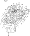
- spring elements 16 two helical compression springs arranged parallel to one another and located between the seat support 4 and the base support 3 inside the mechanism 1 are provided as spring elements 16, as shown in Fig.5
- the functionality is explained below using one of these spring elements 16 as an example.
- the entire mechanism 1 is constructed mirror-symmetrically with respect to its central longitudinal plane, as far as the actual kinematics are concerned. In this respect, the following description always assumes that the structural elements of the actual swivel mechanism are present in pairs on both sides, unless expressly stated otherwise or shown in the figures.
- the functional element 19 is clamped between the seat support 4 and the base support 3, and is therefore supported simultaneously on the seat support 4 and the base support 3.
- both a first support element 21 (upper support element) assigned to the seat support 4 and a second support element 22 (lower support element) assigned to the base support 3 are provided, the together form the support device.
- Each support element 21, 22 has a support surface 23, 24.
- a functional element 19 is attached to this end 18 of the spring element 16, which can act on the spring end 18 in the longitudinal direction 28 of the spring via a suitable coupling element 27, such as an eyelet or a hook.
- the coupling element 27, for example, strikes the end turns of the spring element 16 or is screwed into the spring element 16.
- the spring mechanism 15 and the mechanical components 3, 4, 5 are coordinated in such a way that the rotation axis 36 of the upper support element 21 in the non-pivoted state, ie when the backrest is not pivoted, i.e. when the seat support 4 is still in its basic position, lies on the bearing axis 29 of the functional element 19.
- this enables a "forceless adjustment", i.e. an adjustment of the upper support element 21 without changing the preload of the spring element 16.
- a manually adjustable adjustment device 17 is provided for adjusting the at least one support element, here for pivoting the upper support element 21 about its axis of rotation 36.
- the adjustment device 17 can also be designed to be driven by a motor.
- All means for influencing the operation of the spring mechanism, in particular for adjusting the spring force, in particular the adjustable support element 21 and the adjustment device 17 are, as in the example here, preferably arranged exclusively in the seat support 4 or assigned to the seat support 4.
- the base support 3, which only provides the second support surface can be designed to be lighter and structurally simpler than in conventional mechanisms in which the spring force adjustment takes place in the base support or by means of components attached to the base support.
- the two bearings 31, 32 of the functional element 19 are clamped between the support surfaces 23, 24 of the upper and lower support elements 21, 22.
- the support surface 23 of the upper support element 21 forms a first point of attack on the outer ring of the first bearing 31, while a second point of attack on the outer ring of the second bearing 32 is defined by its contact with the support surface 24 of the lower support element 22.
- the trajectory formed by the support surfaces 23, 24, on which the functional element 19 moves during pivoting of the backrest can play a role.
- the extent of the deflection or the spring stroke is influenced by the locking angle of the scissor arms, or more precisely by the angle of the support surfaces 23, 24 to one another. This can result in both a linear and a non-linear relationship between the swivel angle of the backrest support 5 on the one hand and the swivel force required for this swiveling on the other. This relationship is preferably linear, i.e. the force required by the user to swivel the backrest is always the same regardless of the swivel angle of the backrest.
Landscapes
- Health & Medical Sciences (AREA)
- Dentistry (AREA)
- General Health & Medical Sciences (AREA)
- Chairs Characterized By Structure (AREA)
Description
Die Erfindung betrifft eine Mechanik für ein Sitzmöbel.The invention relates to a mechanism for a seating furniture.
Aus dem Stand der Technik sind zahlreiche Möglichkeiten zur Einstellung des Schwenkwiderstandes einer schwenkbaren Komponente eines Sitzmöbels bekannt. Von Nachteil bei diesen bekannten Lösungen ist zum einen, daß ein hoher Kraftaufwand zum Ändern des Schwenkwiderstandes erforderlich ist, und zum anderen, daß sich der einmal eingestellte Schwenkwiderstand während des Verschwenkens der Komponente verändert. Beides wird von einem Benutzer eines solchen Sitzmöbels als unangenehm empfunden.Numerous options for adjusting the swivel resistance of a swivel component of a piece of seating furniture are known from the state of the art. The disadvantage of these known solutions is that a great deal of force is required to change the swivel resistance and that the swivel resistance, once set, changes while the component is swiveling. Both of these are perceived as unpleasant by the user of such a piece of seating furniture.
Das Dokument
Eine Aufgabe der vorliegenden Erfindung ist es, bei einem Sitzmöbel eine besonders komfortable Einstellung des Schwenkwiderstandes einer Sitzmöbelkomponente zu erreichen.An object of the present invention is to achieve a particularly comfortable adjustment of the swivel resistance of a seating furniture component.
Die Erfindung wird wie in Anspruch 1 definiert durch eine Mechanik für ein Sitzmöbel verwirklicht.The invention is realized as defined in
Die Erfindung wird außerdem verwirklicht durch ein Sitzmöbel, insbesondere einen Bürostuhl, mit einer Mechanik, wie oben beschreiben.The invention is also realized by a piece of seating furniture, in particular an office chair, with a mechanism as described above.
Die Erfindung verwendet das im Bereich der Stuhlmechaniken grundsätzlich bereits bekannte Prinzip der sogenannten "kraftlosen Verstellung" . Das bedeutet, daß die Initialkraft für das Verschwenken der verschwenkbaren Komponente verändert werden kann, ohne daß dabei eine Veränderung der Vorspannung des beteiligten Federelements erfolgt. Dieses Prinzip wird erfindungsgemäß auf eine besonders elegante Art und Weise umgesetzt, nämlich vorzugsweise mit Hilfe eines verstellbaren, insbesondere lage- und/oder positionsveränderlichen Abstützelements, welches, insbesondere dann, wenn sich die verschwenkbare Komponente in einem nicht verschwenkten Zustand befindet, verstellt werden kann, ohne daß das Federelement komprimiert wird (statischer Aspekt der Erfindung), wobei dieses Abstützelement eine von zwei Auflageflächen bereitstellt, an denen sich das Federelement, entweder unmittelbar oder über ein mit dem Federelement zusammenwirkendes Funktionselement, gleichzeitig abstützt. Dabei bewegt sich wenigstens eine dieser beiden Auflageflächen durch das Verschwenken der verschwenkbaren Komponente relativ zu der anderen Auflagefläche derart, daß die beiden Auflageflächen bei einem Verschwenken der verschwenkbaren Komponente nach Art von sich schließenden Armen einer Schere gleichzeitig auf das Federende bzw. das Funktionselement einwirken und dadurch das Federelement in Abhängigkeit von der zuvor eingestellten Lage und/oder Position des verstellbaren Abstützelements komprimieren. Je nach Ausgestaltung des Abstützelements kann dabei die Natur der Schwenkbewegung der Komponente variiert werden (dynamischer Aspekt der Erfindung). So kann u.a. das Schwenkverhalten der Komponente auf einfache Weise beeinflußt und durch den Benutzer selbst entsprechend seiner Wünsche individuell eingestellt werden. Insbesondere läßt sich für das Verschwenken der verschwenkbaren Komponente durch die Gestaltung der Abstützflächen der Abstützelemente das Verhältnis zwischen Federkraft und Federweg einstellen. Genauer gesagt lassen sich solche unterschiedlichen Schwenkverhalten erzielen, wie sie durch die Verwendung von Federelementen mit linearer, progressiver bzw. degressiver Federkennlinie erzielbar sind, ohne daß hierfür jedoch das verwendete Federelement getauscht werden muß.The invention uses the principle of so-called "forceless adjustment" which is already known in the field of chair mechanisms. This means that the initial force for pivoting the pivotable component can be changed without changing the preload of the spring element involved. This principle is implemented in a particularly elegant manner according to the invention, namely preferably with the aid of an adjustable, in particular position- and/or position-variable support element which, in particular when the pivotable component is in a non-pivoted state, can be adjusted without the spring element being compressed (static aspect of the invention), whereby this support element provides one of two support surfaces on which the spring element can rest, either directly or via a functional element that interacts with the spring element. At least one of these two support surfaces moves as a result of the pivoting of the pivotable component relative to the other support surface in such a way that when the pivotable component pivots, the two support surfaces act simultaneously on the spring end or the functional element like the closing arms of a pair of scissors and thereby compress the spring element depending on the previously set location and/or position of the adjustable support element. Depending on the design of the support element, the nature of the pivoting movement of the component can be varied (dynamic aspect of the invention). In this way, the pivoting behavior of the component can be easily influenced and individually adjusted by the user according to his wishes. In particular, the relationship between spring force and spring travel can be adjusted for the pivoting of the pivotable component by the design of the support surfaces of the support elements. More precisely, different swivel behaviors can be achieved by using spring elements with linear, progressive or degressive spring characteristics, without having to replace the spring element used.
Mit der erfindungsgemäßen Lösung wird bei einem Sitzmöbel eine besonders komfortable Einstellung des Schwenkwiderstandes einer Sitzmöbelkomponente erreicht.The solution according to the invention enables a particularly comfortable adjustment of the swivel resistance of a seating furniture component.
Die im Folgenden im Zusammenhang mit der Vorrichtung zum Verstellen des Schwenkwiderstandes erläuterten Vorteile und Ausgestaltungen gelten sinngemäß auch für die erfindungsgemäße Mechanik des Sitzmöbels sowie das Sitzmöbel selbst und umgekehrt.The advantages and embodiments explained below in connection with the device for adjusting the swivel resistance also apply mutatis mutandis to the mechanism of the seating furniture according to the invention as well as to the seating furniture itself and vice versa.
Ein Ausführungsbeispiel der Erfindung wird nachfolgend anhand der Zeichnungen näher erläutert. Hierbei zeigen:
- Fig. 1
- eine Bürostuhlmechanik in einer nicht verschwenkten Grundstellung (geringer Schwenkwiderstand der Rückenlehne, "weiche/leichte Einstellung"), Längsschnitt;
- Fig. 2
- eine Bürostuhlmechanik in einer maximal nach hinten verschwenkten Stellung (geringer Schwenkwiderstand der Rückenlehne, "weiche/leichte Einstellung"), Längsschnitt;
- Fig. 3
- eine Bürostuhlmechanik in einer nicht verschwenkten Grundstellung (hoher Schwenkwiderstand der Rückenlehne, "harte/schwere Einstellung"), Längsschnitt;
- Fig. 4
- eine Bürostuhlmechanik in einer maximal nach hinten verschwenkten Stellung(geringer Schwenkwiederstand der Rückenlehne, "harte/schwere Einstellung"), Längsschnitt;
- Fig. 5
- eine Detailansicht der Federelemente und der Verstellvorrichtung (perspektivisch).
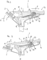
- Fig.1
- an office chair mechanism in a non-pivoted basic position (low swivel resistance of the backrest, "soft/easy adjustment"), longitudinal section;
- Fig.2
- an office chair mechanism in a position swivelled as far back as possible (low swivel resistance of the backrest, "soft/easy adjustment"), longitudinal section;
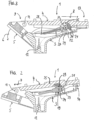
- Fig.3
- an office chair mechanism in a non-swivelled basic position (high swivel resistance of the backrest, "hard/heavy setting"), longitudinal section;
- Fig.4
- an office chair mechanism in a maximally backward tilted position (low swivel resistance of the backrest, "hard/heavy setting"), longitudinal section;
- Fig.5
- a detailed view of the spring elements and the adjustment device (perspective).
Sämtliche Figuren zeigen die Erfindung nicht maßstabsgerecht, dabei lediglich schematisch und nur mit ihren wesentlichen Bestandteilen. Gleiche Bezugszeichen entsprechen dabei Elementen gleicher oder vergleichbarer Funktion.All figures show the invention not to scale, but only schematically and only with its essential components. The same reference symbols correspond to elements with the same or comparable function.
Die Figuren zeigen eine Synchronmechanik 1 für eine korrelierte Sitz-Rückenlehnen-Bewegung eines Bürostuhls, mit einem auf einer Stuhlsäule 2 plazierbaren Basisträger 3, mit einem Sitzträger 4 und mit einem Rückenlehnenträger 5, wobei der Rückenlehnenträger 5 mit dem Sitzträger 4 derart verbunden ist, daß eine Schwenkbewegung des Rückenlehnenträgers 5, wie mit Pfeil 6 angedeutet, von einer in den
Anstelle von gelenkigen Verbindungen können auch alternative Verbindungen zwischen den Mechanikkomponenten 3, 4, 5 vorgesehen sein. So können ausgewählte Mechanikkomponenten, beispielsweise der Rückenlehnenträger 5 und der Basisträger 3 oder der Rückenlehnenträger 5 und der Sitzträger 4, auch einteilig ausgeführt und elastisch miteinander verbunden sein, solange dies die gewünschten Bewegungen der Komponenten untereinander erlaubt.Instead of articulated connections, alternative connections can also be provided between the
Die Mechanik 1 umfaßt einen Federmechanismus 15, der wenigstens ein den Schwenkwiderstand der Rückenlehne beeinflussendes Federelement 16 aufweist. Im hier beschriebenen Beispiel sind als Federelemente 16 zwei parallel zueinander angeordnete, zwischen Sitzträger 4 und Basisträger 3 im Inneren der Mechanik 1 liegende Schraubendruckfedern vorgesehen, wie in
Das durch eine noch genauer erläuterte Verstellvorrichtung 17 angegriffene, in Stuhllängsrichtung 8 gesehen vordere Federende 18 des wenigstens einen Federelements 16 liegt "frei" in dem Sinn, daß es nicht auf klassische Weise an eine Komponente 3, 4, 5 der Mechanik 1 angelenkt ist. Statt dessen stützt sich das vordere Federende 18, wie nachfolgend noch genauer erläutert, über ein an dem Federelement 16 angebrachtes Funktionselement 19 an einer als Widerlager dienenden Abstützeinrichtung ab. Dabei ist das Funktionselement 19 zwischen Sitzträger 4 und Basisträger 3 eingeklemmt, stützt sich also gleichzeitig an Sitzträger 4 und Basisträger 3 ab. Zu diesem Zweck ist sowohl ein dem Sitzträger 4 zugeordnetes, erstes Abstützelement 21 (oberes Abstützelement) als auch ein dem Basisträger 3 zugeordnetes, zweites Abstützelement 22 (unteres Abstützelement) vorgesehen, die gemeinsam die Abstützeinrichtung bilden. Jedes Abstützelement 21, 22 weist eine Abstützfläche 23, 24 auf.The front spring end 18 of the at least one
Die beiden Abstützelemente 21, 22 sind vorzugsweise an ihren jeweiligen Mechanikkomponenten 4, 3 angebracht, d.h. entweder mit diesen verbunden oder als integraler Teil dieser ausgeführt.The two
Wenigstens eines der Abstützelemente 21 ist verstellbar, nämlich lage- und/oder positionsveränderbar, ausgeführt. Zweck dieser Verstellbarkeit des wenigstens einen Abstützelements 21 ist die Veränderung einer Eigenschaft der Bewegung des Federendes 18 des Federelements 21, welche Bewegung im vorliegenden Fall in Stuhllängsrichtung 8 gesehen nach hinten gerichtet ist. Zweck der Verstellbarkeit ist es insbesondere, das Ausmaß der Positionsänderung des Furiktionselements 19 und damit das Ausmaß der Änderung des Schwenkwiderstandes der Rückenlehne bei einem Verschwenken des Rückenlehnenträgers 5 in eine verschwenkte Stellung einzustellen. Ein verstellbares Abstützelement 21 ist vorzugsweise als ein gegenüber dem Grundkörper 25 der entsprechenden Mechanikkomponente 4 beweglicher Teil dieser Mechanikkomponente oder aber, wie im vorliegenden Beispiel, als ein mit dieser Mechanikkbmponente 4 beweglich verbundenes, separates Bauteil ausgebildet.At least one of the
In dem beschriebenen Beispiel ist das zweite Abstützelement 22 als fester, d.h. unverstellbarer, integrierter Bestandteil des Basisträgers 3 und damit ortsfest ausgeführt. Die Abstützfläche 24 dieses zweiten Abstützelements 22 weist eine definierte Oberflächengestaltung aus, so daß sich eine bestimmte Abrollbahn mit einem vorbestimmten Steigungsverlauf ergibt.In the example described, the
Das erste Abstützelement 21 ist im Beispiel positions- und lageveränderlich mit dem Grundkörper 25 des Sitzträgers 4 verbunden, so daß die Abstützfläche 23 des ersten Abstützelements 21 verschiedene Winkel zu der Abstützfläche 24 des zweiten Abstützelements 22 einnehmen kann. Auch die Abstützfläche 23 des ersten Abstützelements 21 weist eine definierte Oberflächengestaltung aus, so daß sich eine bestimmte Abrollbahn mit einem vorbestimmten Steigungsverlauf ergibt. Auf die Verstellbarkeit des ersten Abstützelements 21 wird weiter unten genauer eingegangen.In the example, the
Alternativ zu der soeben beschriebenen einfachen Variante, bei der ausschließlich das obere Abstützelement 21 verstellbar ausgeführt ist, kann anstelle des oberen Abstützelements 21 oder aber zusätzlich zu dem oberen Abstützelement 21 auch das untere Abstützelement 22 verstellbar ausgeführt sein. Hierdurch ergeben sich weitere Möglichkeiten der Beeinflussung der Schwenkbewegung der verschwenkbaren Mechanikkomponente 5, beispielsweise durch die Verwendung von Abstützflächen 23, 24 mit aufeinander abgestimmten Steigungsverläufen.As an alternative to the simple variant just described, in which only the
Mit seinem anderen, in Stuhllängsrichtung 8 gesehen hinteren Ende 26 stützt sich das Federelement 16 auf geeignete Weise an dem Basisträger 3 ab.With its
Das für die Federkraftverstellung interessante, in Stuhllängsrichtung 8 gesehen nach vorn und aufwärts gerichtete, vordere Ende 18 des Federelements 16 steht mit dem Funktionselement 19 in Wirkverbindung. In dem gezeigten Beispiel ist an diesem Ende 18 des Federelements 16 ein Funktionselement 19 angebracht, das über ein geeignetes Koppelelement 27, wie eine Öse oder einen Haken, das Federende 18 in Federlängsrichtung 28 beaufschlagen kann. Das Koppelelement 27 schlägt beispielsweise an den Endwindungen des Federelements 16 an oder ist in das Federelement 16 eingeschraubt.The front end 18 of the
Um Reibung und ein "Sperren" bei der Wechselwirkung des Funktionselements 19 mit den Abstützelementen 21, 22 zu vermeiden, umfaßt das Funktionselement 19 zwei unabhängig voneinander bewegliche, auf einer gemeinsamen Lagerachse 29 angebrachte Lager 31, 32, insbesondere Nagellager oder Kugellager. Es können aber auch andere geeignete Wälzlager oder auch Gleitlager verwendet werden. Das Koppelelement 27 verbindet die Lagerachse 29 mit dem Federelement 16, in dem hier illustrierten Beispiel dadurch, daß die Öse oder der Haken des Koppelelements 27 die Lagerachse 29 zumindest teilweise umgreift. Die Lager 31, 32 sind auf der Lagerachse 29 nebeneinander angeordnet, lediglich durch das Koppelelement 27 voneinander getrennt.In order to avoid friction and "locking" when the
Im Gebrauchszustand stützt sich gleichzeitig das erste Lager 31 des Funktionselements 19 an der Abstützfläche 23 des oberen Abstützelements 21 und das zweite Lager 32 des Funktionselements 19 an der Abstützfläche 24 des unteren Abstützelements 22 ab bzw. die Lager 31, 32 rollen gleichzeitig an den Abstützflächen 23, 24 ab, wenn sich die Komponenten zueinander bewegen, insbesondere wenn sich der von dem Rückenlehnenträger 5 mitgenommene Sitzträger 4 relativ zu dem feststehenden Basisträger 3 bewegt.In the state of use, the
Das obere Abstützelement 21 ist verstellbar, genauer gesagt stellungsveränderlich ausgeführt. Dabei ist das verstellbare Abstützelement 21 an dem Sitzträger 3 vorzugsweise derart angeordnet, daß eine Verstellung (Lage- und Positionsänderung) des Abstützelements 21 keine Beaufschlagung, insbesondere keine Positionsänderung des mit dem Federelement 16 zusammenwirkenden Funktionselements 19 hervorruft.The
Während die Abstützfläche 23 des oberen Abstützelements 21 in Richtung der Oberfläche der Mantelfläche des Lagers 31 des Funktionselements 19 zeigt, also an der Innenseite 33 des Abstützelements 21 ausgebildet ist, ist die Außenseite 34 des Abstützelements 21 zumindest abschnittsweise konvex ausgebildet und liegt dort in einer entsprechend konkav ausgeformten Aufnahmeschale 35 an der Unterseite des Grundkörpers 25 des Sitzträgers 4 ein.While the
Bei einer Verstellung des Abstützelements 21 und seiner damit verbundenen Lage- und Ortsveränderung relativ zu dem Sitzträger 4 ist das Abstützelement 21 in der Aufnahmeschale 35 geführt. Das Abstützelement 21 gleitet in der Aufnahmeschale 35 und dreht sich dabei um eine quer zur Stuhllängsrichtung 8 liegende Drehachse 36.When the
Das obere Abstützelement 21 liegt, um seine Drehachse 36 drehbar, ortsfest im Sitzträger 4. Zu diesem Zweck sind an den beiden seitlichen Enden des oberen Abstützelements 21 Lagerzapfen 37 vorgesehen, die in entsprechenden Lagerbuchsen (nicht abgebildet) einliegen, die an beiden Seiten des Sitzträgers 4 an dessen Grundkörper 25 angebracht sind. Die für die Lagerung der Lager 31, 32 des Funktionselements 19 dienende Lagerachse 29 liegt hingegen frei, d.h. sie ist weder mit dem Sitzträger 4 noch mit einer anderen Mechanikkomponente fest verbunden, so daß sie sich, plaziert zwischen den Abstützflächen 23, 24 des oberen und unteren Abstützelements 21, 22, durch diese beaufschlagt bewegen kann.The
Der Federmechanismus 15 und die Mechanikkomponenten 3, 4, 5 sind derart aufeinander abgestimmt, daß die Drehachse 36 des oberen Abstützelements 21 im unverschwenkten Zustand, d.h. bei nicht verschwenkter Rückenlehne, wenn sich also auch der Sitzträger 4 noch in seiner Grundstellung befindet, auf der Lagerachse 29 des Funktionselements 19 liegt. Dadurch ist bei einem Verstellen des oberen Abstützelements 21 in diesem unverschwenkten Zustand ein Abwälzen der Abstützfläche 23 des Abstützelements 21 um die Mantelfläche des Lagers 31 des Funktionselements 19 möglich, ohne daß sich die Position des Lagers 31 ändert. Mit anderen Worten ist dadurch eine "kraftlose Verstellung" möglich, also eine Verstellung des oberen Abstützelements 21 ohne eine Änderung der Vorspannung des Federelements 16.The
Vorzugsweise ist eine manuell verstellbare Verstellvorrichtung 17 zum Verstellen des wenigstens einen Abstützelements, hier zum Verschwenken des oberen Abstützelements 21 um seine Drehachse 36, vorgesehen. Alternativ dazu kann die Verstellvorrichtung 17 aber auch motorisch antreibbar ausgeführt sein.Preferably, a manually adjustable adjustment device 17 is provided for adjusting the at least one support element, here for pivoting the
In dem hier gezeigten Beispiel ist an dem oberen Abstützelement 21 ein von der Drehachse 36 beabstandet angeordneter Hebelarm 38 als integrierter Mitnehmer vorgesehen. Der Hebelarm 38 ist zweigeteilt ausgeführt. Die beiden Hebelarmhälften 39 sind gleichgerichtet, jedoch voneinander beabstandet an der dem Doppellager 31, 32 gegenüberliegenden Außenseite 34 des oberen Abstützelements 21 angebracht.In the example shown here, a lever arm 38 arranged at a distance from the axis of
Zwischen den Hebelarmhälften 39 ist ein Bewegungsgewinde (Spindeltrieb) der Verstellvorrichtung 17 positioniert, mit einer Gewindespindel 41 und mit einer auf der Gewindespindel 41 beweglich geführten Gewindemutter 42, wobei die Gewindemutter 42 mit seitlich an ihr angebrachten Zapfen 43 in die Hebelarmhälften 39 eingreift. Zur Aufnahme der Zapfen 43 der Gewindemutter 42 sind in jeder Hebelarmhälfte 39 als Langlöcher ausgeführte Ausnehmungen 44 vorgesehen, die sich in Hebelarmlängsrichtung erstrecken. Diese Ausnehmungen 44 gewährleisten eine rotatorische Entkopplung und damit den benötigten zusätzlichen Freiheitsgrad zur Verstellung des oberen Abstützelements 21 durch den Spindeltrieb.A movement thread (spindle drive) of the adjustment device 17 is positioned between the lever arm halves 39, with a threaded
Zur Verstellung des oberen Abstützelements 21 wird die Drehbewegung der in Stuhllängsrichtung 8 angeordneten Gewindespindel 41 über die Gewindemutter 42 mit Hilfe des Hebelarms 38 auf das obere Abstützelement 21 übertragen, so daß sich das Abstützelement 21 um seine Drehachse 36 verschwenkt. Der Antrieb der Gewindespindel 41 erfolgt beispielsweise über ein Kegelradgetriebe oder dergleichen mit Hilfe einer nicht näher dargestellten Antriebsvorrichtung, die beispielsweise ein Handrad oder dergleichen als Handhabe aufweisen kann.To adjust the
Der Spindeltrieb ist selbsthemmend ausgeführt. Mit anderen Worten verhindert die Ausführung der Gewindespindel 41, daß sich das obere Abstützelement 21 selbsttätig verstellt.The spindle drive is designed to be self-locking. In other words, the design of the threaded
Alle Mittel zur Beeinflussung der Wirkungsweise des Federmechanismus, insbesondere zur Federkraftverstellung, insbesondere das verstellbare Abstützelement 21 und die Verstellvorrichtung 17 sind, wie in dem hiesigen Beispiel, vorzugsweise ausschließlich im Sitzträger 4 angeordnet bzw. dem Sitzträger 4 zugeordnet. Dadurch kann der Basisträger 3, der lediglich die zweite Abstützfläche bereitstellt, leichter und konstruktiv einfacher gestaltet werden als bei herkömmlichen Mechaniken, bei denen die Federkraftverstellung im Basisträger bzw. mittels am Basisträger angebrachten Bauteilen erfolgt.All means for influencing the operation of the spring mechanism, in particular for adjusting the spring force, in particular the
Nachdem das obere Abstützelement 21 in eine gewünschte Stellung überführt worden ist, beispielsweise in eine besonders "weiche" bzw. "leichte" Einstellung, wie in
Durch das Abstützen des Federelements 16 an den beiden Abstützelementen 21, 22 bewegt sich, aufgrund der Relativbewegung des Sitzträgers 4 zu dem Basisträger 3 bei einem Verschwenken des Rückenlehnenträgers 5 in eine verschwenkte Stellung, das Funktionselement 19 in Stuhllängsrichtung 8 gesehen nach hinten bzw. nach hinten unten. Das bewirkt eine Beaufschlagung des wenigstens einen Federelements 16 und damit eine Veränderung des Schwenkwiderstandes der Rückenlehne.By supporting the
Die beiden Lager 31, 32 des Funktionselements 19 sind zwischen den Abstützflächen 23, 24 des oberen und unteren Abstützelements 21, 22 verklemmt. Dabei bildet die Abstützfläche 23 des oberen Abstützelements 21 einen ersten Angriffspunkt auf dem Außenring des ersten Lagers 31, während ein zweiter Angriffspunkt auf dem Außenring des zweiten Lagers 32 durch dessen Berührung mit der Abstützfläche 24 des unteren Abstützelements 22 definiert wird. Bei einem Verschwenken des Rückenlehnenträgers 5 werden die Lager 31, 32 und damit das gesamte Funktionselement 19 durch das sich mit dem Sitzträger 4 mit nach hinten bewegende obere Abstützelement 21 auf der Abstützfläche 24 des unteren Abstützelements 22 nach vorn gedrückt ("Scherenprinzip"). Die Lager 31, 32 und damit die Angriffspunkte der Lager 31, 32 auf den Abstützflächen 23, 24 wandern zwangsweise in Stuhllängsrichtung 8 nach hinten. Es erfolgt eine Änderung von Position und Lage der Abstützfläche 23 des oberen Abstützelements 21 relativ zu der feststehenden Abstützfläche 24 des unteren Abstützelements 22.The two
Anders ausgedrückt fährt der Sitzträger 4, der bei einem Verschwenken des Rückenlehnenträgers 5 von den Rückenlehnenträger 5 mitgenommen wird, nach hinten unten. Aufgrund dieser Bewegung des Sitzträgers 4 wird auch das obere Abstützelement 21 nach hinten unten mitgenommen bzw. bewegt und beaufschlagt somit über das Funktionselement 19 das Federelement 16, so daß es zu einer Komprimierung des Federelements 16 kommt. Der sich an die Rückenlehne anlehnende Benutzer spürt einen Schwenkwiderstand.In other words, the seat support 4, which is carried along by the
Oberes und unteres Abstützelement 21, 22, genauer gesagt deren Abstützflächen 23, 24, bilden dabei die "Arme" einer Schere. Während sich bei einer Parallellage dieser beiden Abstützflächen 23, 24 bei einer Bewegung des Sitzträgers 4 und damit des oberen Abstützelements 21 nach hinten überhaupt kein Verstellweg des Funktionselements 19 bzw. kein Federhub des Federelements 16 ergeben würde, läßt sich durch eine gezielte Verstellung des oberen Abstützelements 21, vorzugsweise "kraftlos" durchgeführt, eine definierte Winkelstellung der beiden Abstützflächen 23, 24 zueinander erzielen (statischer Aspekt) und damit die Bewegung des Funktionselements 19 und damit die Wirkungsweise des Federelements 16 verändern (dynamischer Aspekt).The upper and
Bei der "weichen" bzw. "leichten" Einstellung, bei der die Abstützflächen 23, 24 der beiden Abstützelemente 21, 22 von Sitzträger 4 und Basisträger 3 einen vergleichsweise spitzen Winkel zueinander einschließen (
In der "harten" bzw. "schweren" Einstellung, bei der die Abstützfläche 23 des oberen Abstützelements 21 nahezu senkrecht zu der Federlängsrichtung 28 steht (
Im Zusammenhang damit kann die durch die Abstützflächen 23, 24 gebildete Bahnkurve eine Rolle spielen, auf der sich das Funktionselement 19 während eines Verschwenkens der Rückenlehne bewegt.In this context, the trajectory formed by the support surfaces 23, 24, on which the
Die Abstützfläche 23 des oberen Abstützelements 21 ist gewölbt, im vorliegenden Fall sowohl abschnittsweise konvex als auch abschnittsweise konkav ausgeführt. Die Abstützfläche 24 des unteren Abstützelements 22 ist eben ausgeführt und verläuft schräg, nämlich in Stuhllängsrichtung 8 gesehen von vorn nach hinten abfallend. Durch die Gestaltung der beiden Abstützflächen 23, 24, insbesondere jedoch durch die Gestaltung der Abstützfläche 23 des oberen Abstützelements 21, ergibt sich eine definierte, nichtlineare Bahnkurve des Funktionselements 19 bei einem Verschwenken der Rückenlehne nach hinten. Somit verändert sich der Schwenkwiderstand während des Verschwenkens der Rückenlehne. Insbesondere kann durch die Gestaltung der Abstützflächen der von einem Benutzer "gefühlte" Ablauf der Mechanik beeinflußt werden. Beispielsweise kann im verschwenkten Zustand, kurz bevor die Rückenlehne in ihrer Maximalverschwenkung anschlägt, noch eine leichte Progressivität erreicht werden. Durch die gewählte Wölbung der Abstützfläche 23 ergibt sich eine besonders angenehme Bewegungscharakteristik der Mechanik 1. Vorzugsweise ist gewölbte Abstützfläche 23 derart ausgeführt, daß der von einem Benutzer empfundene Kraftaufwand bei einem Verschwenken der Rückenlehne immer konstant ist.The
Mit der Wölbung der Abstützflächen, insbesondere der Abstützfläche 23 des oberen Abstützelements 21, wird das Maß der Auslenkung des Funktionselements 19 und damit das Maß der Auslenkung des vorderen Federendes 18, der Federhub, beeinflußt. Somit kann beeinflußt werden, ob sich die Mechanik 1 progressiv, linear oder degressiv verhält.The curvature of the support surfaces, in particular the
Das Maß der Auslenkung bzw. des Federhubs wird von dem Verschlußwinkel der Scherenarme, genauer gesagt von dem Winkel der Abstützflächen 23, 24 zueinander, beeinflußt. Dabei kann sich sowohl ein linearer als auch ein nichtlinearer Zusammenhang zwischen dem Schwenkwinkel des Rückenlehnenträgers 5 einerseits und der für diese Verschwenkung benötigte Schwenkkraft andererseits ergeben. Vorzugsweise ist dieser Zusammenhang linear, d.h. der von dem Benutzer aufzubringende Kraftaufwand für ein Verschwenken der Rückenlehne ist unabhängig von dem Schwenkwinkel der Rückenlehne immer gleich.The extent of the deflection or the spring stroke is influenced by the locking angle of the scissor arms, or more precisely by the angle of the support surfaces 23, 24 to one another. This can result in both a linear and a non-linear relationship between the swivel angle of the
Das oben beschriebene Beispiel verwendet eine Vorrichtung zum Einstellen des Schwenkwiderstandes einer verschwenkbaren Komponente eines Sitzmöbels. Bei der verschwenkbaren Komponente handelt es sich vorzugsweise um den Rückenlehnenträger 5 einer Stuhlmechanik 1 eines Bürostuhls, wobei es sich bei der Stuhlmechanik 1 vorzugsweise um eine Synchronmechanik handelt. Dabei weist das Sitzmöbel einen Federmechanismus 15 auf. Der Federmechanismus 15 umfaßt ein den Schwenkwiderstand der verschwenkbaren Komponente 5 beeinflussendes Federelement 16. Das Sitzmöbel weist neben der verschwenkbaren Komponente 5 zwei weitere Komponenten 3, 4 auf. Bei diesen zwei weiteren Komponenten handelt es sich vorzugsweise um den Basisträger 3 und den Sitzträger 4 der Stuhlmechanik 1. Wenigstens eine dieser zwei weiteren Komponenten, vorzugsweise der Sitzträger 4, wird durch ein Verschwenken der verschwenkbaren Komponente, hier vorzugsweise durch das Verschwenken des Rückenlehnenträgers 5 nach hinten unten, mitbewegt. Das Federelement 16 stützt sich mit seinem einen Federende 18 oder mit einem mit diesem Federende 18 zusammenwirkenden Funktionselement 19 gleichzeitig an zwei der drei Komponenten ab, nämlich vorzugsweise an dem Basisträger 3 und dem Sitzträger 4. In einer alternativen, nicht in den Figuren gezeigten Ausgestaltung kann sich auch das hintere Ende 26 des Federelements 16 an dem Rückenlehnenträger 5 abstützen. Bei einer dieser beiden zur Abstützung dienenden Komponenten handelt es sich um die mitbewegte oder die verschwenkbare Komponente, also vorzugsweise um den Sitzträger 4 oder aber alternativ um den Rückenlehnenträger 5. Dieser einen (mitbewegten oder verschwenkbaren) Komponente, vorzugsweise also dem Sitzträger 4 oder alternativ dem Rückenlehnenträger 5, und/oder der anderen zur Abstützung dienende Komponente, vorzugsweise also dem Basisträger 3, ist zum Zweck des Abstützens des Federendes 18 oder des Funktionselements 19 ein Abstützelement 21 zugeordnet, dessen Lage und/oder Position zum Einstellen des Schwenkwiderstandes der verschwenkbaren Komponente 5 veränderbar ist.The example described above uses a device for adjusting the swivel resistance of a swivel component of a piece of seating furniture. The swivel component is preferably the
Alle in der Beschreibung, den nachfolgenden Ansprüchen und der Zeichnung dargestellten Merkmale können sowohl einzeln als auch in beliebiger Kombination miteinander im Rahmen der Patentansprüche erfindungswesentlich sein.All features presented in the description, the following claims and the drawings can be essential to the invention both individually and in any combination with one another within the scope of the patent claims.
- 11
- Mechanikmechanics
- 22
- StuhlsäuleChair column
- 33
- BasisträgerBase carrier
- 44
- SitzträgerSeat support
- 55
- RückenlehnenträgerBackrest support
- 66
- Richtung der SchwenkbewegungDirection of swivel movement
- 77
- Richtung der FolgebewegungDirection of follow-up movement
- 88th
- StuhllängsrichtungChair length direction
- 99
- hinteres Sitzträgerenderear seat support end
- 1010
- (frei)(free)
- 1111
- erste Querachsefirst transverse axis
- 1212
- zweite Querachsesecond transverse axis
- 1313
- vorderes Sitzträgerendefront seat support end
- 1414
- Dreh-/SchiebegelenkSwivel/sliding joint
- 1515
- FedermechanismusSpring mechanism
- 1616
- FederelementSpring element
- 1717
- VerstellvorrichtungAdjustment device
- 1818
- vorderes Federendefront spring end
- 1919
- FunktionselementFunctional element
- 2020
- (frei)(free)
- 2121
- erstes (oberes) Abstützelementfirst (upper) support element
- 2222
- zweites (unteres) Abstützelementsecond (lower) support element
- 2323
- erste Abstützflächefirst support surface
- 2424
- zweite Abstützflächesecond support surface
- 2525
- Sitzträger-GrundkörperSeat support base body
- 2626
- hinteres Federenderear spring end
- 2727
- KoppelelementCoupling element
- 2828
- FederlängsrichtungSpring longitudinal direction
- 2929
- LagerachseBearing axis
- 3030
- (frei)(free)
- 3131
- erstes Lagerfirst camp
- 3232
- zweites Lagersecond camp
- 3333
- Abstützelement-InnenseiteSupport element inside
- 3434
- Abstützelement-AußenseiteSupport element outside
- 3535
- AufnahmeschaleHolder
- 3636
- DrehachseRotation axis
- 3737
- LagerzapfenBearing journal
- 3838
- HebelarmLever arm
- 3939
- HebelarmhälfteLever arm half
- 4040
- (frei)(free)
- 4141
- GewindespindelThreaded spindle
- 4242
- GewindemutterThreaded nut
- 4343
- Zapfencone
- 4444
- LanglochLong hole
Claims (5)
- Mechanism (1) for a piece of seating furniture, in particular synchronizing mechanism for a correlated seat/backrest movement of a piece of seating furniture, in particular an office chair, having a base support (3) which is able to be placed on a chair column (2), having a seat support (4) and having a backrest support (5), wherein the backrest support (5) is connected to the seat support (4) in such a way that a pivoting movement of the backrest support (5) from a home position into a rearwardly pivoted position induces a movement of the seat support (4) relative to the base support (3), wherein a spring mechanism (15) is provided, said spring mechanism (15) having at least one spring element (16) which influences the pivoting resistance of the backrest and of which one end (18) is operatively connected to at least one functional element (19), wherein the at least one functional element (19) is supported against a supporting device which has both a first supporting element (21), arranged on the seat support (4), and a second supporting element (22), arranged on the base support (3), wherein at least one of said supporting elements (21) is configured to be adjustable, in particular variable in terms of location and/or position, and wherein the at least one functional element (19) is supported against both supporting elements (21, 22) at the same time, and wherein, by way of the adjustment of the at least one adjustable supporting element (21), an angle included by supporting surfaces (23, 24) of the two supporting elements (21, 22) is variable, wherein, due to this variation in the angle, when the backrest support (5) is pivoted, the movement of the functional element (19) and thus the functioning of the spring element (16) changes in a manner dependent on said angle.
- Mechanism according to Claim 1, wherein the functional element (19) comprises two bearings (31, 32), preferably provided on a common bearing shaft (29), which are movable independently of one another.
- Mechanism according to Claim 2, wherein one bearing (31) is supported against one supporting element (21) and the other bearing (32) is supported against the other supporting element (22) .
- Mechanism according to Claim 3, wherein the first supporting element (21) is rotatable about an axis of rotation (36), which is preferably positioned transversely to the chair longitudinal direction (8), wherein the position of the axis of rotation (36) coincides with the position of the bearing shaft (29) during the adjustment of the supporting element (21) in the home position of the backrest support (5).
- Piece of seating furniture, in particular office chair, having a mechanism (1) according to one of Claims 1 to 4.
Applications Claiming Priority (1)
| Application Number | Priority Date | Filing Date | Title |
|---|---|---|---|
| DE102018127685.0A DE102018127685A1 (en) | 2018-11-06 | 2018-11-06 | Setting the pivoting resistance of a pivotable component of a piece of seating furniture |
Publications (2)
| Publication Number | Publication Date |
|---|---|
| EP3649893A1 EP3649893A1 (en) | 2020-05-13 |
| EP3649893B1 true EP3649893B1 (en) | 2024-07-03 |
Family
ID=68468527
Family Applications (1)
| Application Number | Title | Priority Date | Filing Date |
|---|---|---|---|
| EP19000496.0A Active EP3649893B1 (en) | 2018-11-06 | 2019-11-04 | Adjusting the pivotal resistance of a component of seating furniture |
Country Status (2)
| Country | Link |
|---|---|
| EP (1) | EP3649893B1 (en) |
| DE (1) | DE102018127685A1 (en) |
Families Citing this family (2)
| Publication number | Priority date | Publication date | Assignee | Title |
|---|---|---|---|---|
| US11690455B2 (en) * | 2020-09-18 | 2023-07-04 | Dinkar Chellaram | Synchronous-tilt reclining chair |
| NO348787B1 (en) * | 2023-09-13 | 2025-06-02 | Flokk Sp Z O O | Tension adjustment system for chair mechanism |
Citations (1)
| Publication number | Priority date | Publication date | Assignee | Title |
|---|---|---|---|---|
| EP1358821B1 (en) * | 2002-04-30 | 2006-04-05 | Klöber Gmbh & Co. | Office chair with a user-weight-dependent energy storage device |
Family Cites Families (1)
| Publication number | Priority date | Publication date | Assignee | Title |
|---|---|---|---|---|
| DE202015100511U1 (en) * | 2015-02-03 | 2016-05-04 | Bock 1 Gmbh & Co. Kg | synchronous mechanism |
-
2018
- 2018-11-06 DE DE102018127685.0A patent/DE102018127685A1/en not_active Withdrawn
-
2019
- 2019-11-04 EP EP19000496.0A patent/EP3649893B1/en active Active
Patent Citations (1)
| Publication number | Priority date | Publication date | Assignee | Title |
|---|---|---|---|---|
| EP1358821B1 (en) * | 2002-04-30 | 2006-04-05 | Klöber Gmbh & Co. | Office chair with a user-weight-dependent energy storage device |
Also Published As
| Publication number | Publication date |
|---|---|
| EP3649893A1 (en) | 2020-05-13 |
| DE102018127685A1 (en) | 2020-05-07 |
Similar Documents
| Publication | Publication Date | Title |
|---|---|---|
| EP1454568B1 (en) | Chair, particularly office-chair | |
| DE102015106386B4 (en) | Armrest assembly for a seat, in particular for a vehicle seat and vehicle seat | |
| DE102014117101B4 (en) | Armrest assembly for a seat, in particular for a vehicle seat and vehicle seat | |
| EP2926690B1 (en) | Mechanism for an office chair | |
| AT16873U1 (en) | Actuator for furniture flaps | |
| WO2011141107A1 (en) | Adjusting mechanism for adjusting a restoring force that acts on a backrest of a chair, and office chair with such an adjusting mechanism | |
| EP2084992A2 (en) | Seating furniture and cover for same | |
| EP3120732B1 (en) | Mechanism for an office chair | |
| AT12867U1 (en) | seating | |
| DE102014226645A1 (en) | Adjustment mechanism for adjusting a force acting on a backrest of a chair restoring force and office chair with such adjustment mechanism | |
| DE102004053965B4 (en) | chair | |
| DE102014109438A1 (en) | Mechanics for an office chair | |
| DE102006023982A1 (en) | chair | |
| EP3649893B1 (en) | Adjusting the pivotal resistance of a component of seating furniture | |
| EP3387957B1 (en) | Synchronising mechanism for an office chair | |
| DE102008045489A1 (en) | Mechanics for an office chair | |
| DE102005017634B4 (en) | Vehicle seat with deformable S-shaped backrest | |
| EP1258212B1 (en) | Chair, particularly office-chair, with adjustably preloaded backrest | |
| EP1850699B1 (en) | Piece of furniture in particular a seat | |
| EP3023297B1 (en) | Vehicle seat with a backrest that can be pivoted including armrest | |
| EP3973820A1 (en) | Mechanism for a chair | |
| DE202009009612U1 (en) | chair | |
| DE10123231C2 (en) | office chair | |
| DE102010026787B4 (en) | Mechanics for an office chair | |
| EP1874160A1 (en) | Seating, especially office chair |
Legal Events
| Date | Code | Title | Description |
|---|---|---|---|
| PUAI | Public reference made under article 153(3) epc to a published international application that has entered the european phase |
Free format text: ORIGINAL CODE: 0009012 |
|
| STAA | Information on the status of an ep patent application or granted ep patent |
Free format text: STATUS: THE APPLICATION HAS BEEN PUBLISHED |
|
| AK | Designated contracting states |
Kind code of ref document: A1 Designated state(s): AL AT BE BG CH CY CZ DE DK EE ES FI FR GB GR HR HU IE IS IT LI LT LU LV MC MK MT NL NO PL PT RO RS SE SI SK SM TR |
|
| AX | Request for extension of the european patent |
Extension state: BA ME |
|
| STAA | Information on the status of an ep patent application or granted ep patent |
Free format text: STATUS: REQUEST FOR EXAMINATION WAS MADE |
|
| 17P | Request for examination filed |
Effective date: 20201014 |
|
| RBV | Designated contracting states (corrected) |
Designated state(s): AL AT BE BG CH CY CZ DE DK EE ES FI FR GB GR HR HU IE IS IT LI LT LU LV MC MK MT NL NO PL PT RO RS SE SI SK SM TR |
|
| STAA | Information on the status of an ep patent application or granted ep patent |
Free format text: STATUS: EXAMINATION IS IN PROGRESS |
|
| 17Q | First examination report despatched |
Effective date: 20220714 |
|
| GRAP | Despatch of communication of intention to grant a patent |
Free format text: ORIGINAL CODE: EPIDOSNIGR1 |
|
| STAA | Information on the status of an ep patent application or granted ep patent |
Free format text: STATUS: GRANT OF PATENT IS INTENDED |
|
| INTG | Intention to grant announced |
Effective date: 20240205 |
|
| GRAS | Grant fee paid |
Free format text: ORIGINAL CODE: EPIDOSNIGR3 |
|
| GRAA | (expected) grant |
Free format text: ORIGINAL CODE: 0009210 |
|
| STAA | Information on the status of an ep patent application or granted ep patent |
Free format text: STATUS: THE PATENT HAS BEEN GRANTED |
|
| P01 | Opt-out of the competence of the unified patent court (upc) registered |
Effective date: 20240515 |
|
| AK | Designated contracting states |
Kind code of ref document: B1 Designated state(s): AL AT BE BG CH CY CZ DE DK EE ES FI FR GB GR HR HU IE IS IT LI LT LU LV MC MK MT NL NO PL PT RO RS SE SI SK SM TR |
|
| REG | Reference to a national code |
Ref country code: CH Ref legal event code: EP |
|
| REG | Reference to a national code |
Ref country code: DE Ref legal event code: R096 Ref document number: 502019011538 Country of ref document: DE |
|
| REG | Reference to a national code |
Ref country code: LT Ref legal event code: MG9D |
|
| REG | Reference to a national code |
Ref country code: NL Ref legal event code: MP Effective date: 20240703 |
|
| PG25 | Lapsed in a contracting state [announced via postgrant information from national office to epo] |
Ref country code: PT Free format text: LAPSE BECAUSE OF FAILURE TO SUBMIT A TRANSLATION OF THE DESCRIPTION OR TO PAY THE FEE WITHIN THE PRESCRIBED TIME-LIMIT Effective date: 20241104 |
|
| PG25 | Lapsed in a contracting state [announced via postgrant information from national office to epo] |
Ref country code: NL Free format text: LAPSE BECAUSE OF FAILURE TO SUBMIT A TRANSLATION OF THE DESCRIPTION OR TO PAY THE FEE WITHIN THE PRESCRIBED TIME-LIMIT Effective date: 20240703 |
|
| PG25 | Lapsed in a contracting state [announced via postgrant information from national office to epo] |
Ref country code: PT Free format text: LAPSE BECAUSE OF FAILURE TO SUBMIT A TRANSLATION OF THE DESCRIPTION OR TO PAY THE FEE WITHIN THE PRESCRIBED TIME-LIMIT Effective date: 20241104 Ref country code: NL Free format text: LAPSE BECAUSE OF FAILURE TO SUBMIT A TRANSLATION OF THE DESCRIPTION OR TO PAY THE FEE WITHIN THE PRESCRIBED TIME-LIMIT Effective date: 20240703 |
|
| PGFP | Annual fee paid to national office [announced via postgrant information from national office to epo] |
Ref country code: DE Payment date: 20240905 Year of fee payment: 6 |
|
| PG25 | Lapsed in a contracting state [announced via postgrant information from national office to epo] |
Ref country code: NO Free format text: LAPSE BECAUSE OF FAILURE TO SUBMIT A TRANSLATION OF THE DESCRIPTION OR TO PAY THE FEE WITHIN THE PRESCRIBED TIME-LIMIT Effective date: 20241003 |
|
| PG25 | Lapsed in a contracting state [announced via postgrant information from national office to epo] |
Ref country code: GR Free format text: LAPSE BECAUSE OF FAILURE TO SUBMIT A TRANSLATION OF THE DESCRIPTION OR TO PAY THE FEE WITHIN THE PRESCRIBED TIME-LIMIT Effective date: 20241004 Ref country code: FI Free format text: LAPSE BECAUSE OF FAILURE TO SUBMIT A TRANSLATION OF THE DESCRIPTION OR TO PAY THE FEE WITHIN THE PRESCRIBED TIME-LIMIT Effective date: 20240703 Ref country code: PL Free format text: LAPSE BECAUSE OF FAILURE TO SUBMIT A TRANSLATION OF THE DESCRIPTION OR TO PAY THE FEE WITHIN THE PRESCRIBED TIME-LIMIT Effective date: 20240703 |
|
| PG25 | Lapsed in a contracting state [announced via postgrant information from national office to epo] |
Ref country code: BG Free format text: LAPSE BECAUSE OF FAILURE TO SUBMIT A TRANSLATION OF THE DESCRIPTION OR TO PAY THE FEE WITHIN THE PRESCRIBED TIME-LIMIT Effective date: 20240703 |
|
| PG25 | Lapsed in a contracting state [announced via postgrant information from national office to epo] |
Ref country code: LV Free format text: LAPSE BECAUSE OF FAILURE TO SUBMIT A TRANSLATION OF THE DESCRIPTION OR TO PAY THE FEE WITHIN THE PRESCRIBED TIME-LIMIT Effective date: 20240703 |
|
| PG25 | Lapsed in a contracting state [announced via postgrant information from national office to epo] |
Ref country code: IS Free format text: LAPSE BECAUSE OF FAILURE TO SUBMIT A TRANSLATION OF THE DESCRIPTION OR TO PAY THE FEE WITHIN THE PRESCRIBED TIME-LIMIT Effective date: 20241103 |
|
| PG25 | Lapsed in a contracting state [announced via postgrant information from national office to epo] |
Ref country code: HR Free format text: LAPSE BECAUSE OF FAILURE TO SUBMIT A TRANSLATION OF THE DESCRIPTION OR TO PAY THE FEE WITHIN THE PRESCRIBED TIME-LIMIT Effective date: 20240703 Ref country code: CZ Free format text: LAPSE BECAUSE OF FAILURE TO SUBMIT A TRANSLATION OF THE DESCRIPTION OR TO PAY THE FEE WITHIN THE PRESCRIBED TIME-LIMIT Effective date: 20240703 |
|
| PG25 | Lapsed in a contracting state [announced via postgrant information from national office to epo] |
Ref country code: RS Free format text: LAPSE BECAUSE OF FAILURE TO SUBMIT A TRANSLATION OF THE DESCRIPTION OR TO PAY THE FEE WITHIN THE PRESCRIBED TIME-LIMIT Effective date: 20241003 Ref country code: ES Free format text: LAPSE BECAUSE OF FAILURE TO SUBMIT A TRANSLATION OF THE DESCRIPTION OR TO PAY THE FEE WITHIN THE PRESCRIBED TIME-LIMIT Effective date: 20240703 |
|
| PG25 | Lapsed in a contracting state [announced via postgrant information from national office to epo] |
Ref country code: RS Free format text: LAPSE BECAUSE OF FAILURE TO SUBMIT A TRANSLATION OF THE DESCRIPTION OR TO PAY THE FEE WITHIN THE PRESCRIBED TIME-LIMIT Effective date: 20241003 Ref country code: PL Free format text: LAPSE BECAUSE OF FAILURE TO SUBMIT A TRANSLATION OF THE DESCRIPTION OR TO PAY THE FEE WITHIN THE PRESCRIBED TIME-LIMIT Effective date: 20240703 Ref country code: NO Free format text: LAPSE BECAUSE OF FAILURE TO SUBMIT A TRANSLATION OF THE DESCRIPTION OR TO PAY THE FEE WITHIN THE PRESCRIBED TIME-LIMIT Effective date: 20241003 Ref country code: LV Free format text: LAPSE BECAUSE OF FAILURE TO SUBMIT A TRANSLATION OF THE DESCRIPTION OR TO PAY THE FEE WITHIN THE PRESCRIBED TIME-LIMIT Effective date: 20240703 Ref country code: IS Free format text: LAPSE BECAUSE OF FAILURE TO SUBMIT A TRANSLATION OF THE DESCRIPTION OR TO PAY THE FEE WITHIN THE PRESCRIBED TIME-LIMIT Effective date: 20241103 Ref country code: HR Free format text: LAPSE BECAUSE OF FAILURE TO SUBMIT A TRANSLATION OF THE DESCRIPTION OR TO PAY THE FEE WITHIN THE PRESCRIBED TIME-LIMIT Effective date: 20240703 Ref country code: GR Free format text: LAPSE BECAUSE OF FAILURE TO SUBMIT A TRANSLATION OF THE DESCRIPTION OR TO PAY THE FEE WITHIN THE PRESCRIBED TIME-LIMIT Effective date: 20241004 Ref country code: FI Free format text: LAPSE BECAUSE OF FAILURE TO SUBMIT A TRANSLATION OF THE DESCRIPTION OR TO PAY THE FEE WITHIN THE PRESCRIBED TIME-LIMIT Effective date: 20240703 Ref country code: ES Free format text: LAPSE BECAUSE OF FAILURE TO SUBMIT A TRANSLATION OF THE DESCRIPTION OR TO PAY THE FEE WITHIN THE PRESCRIBED TIME-LIMIT Effective date: 20240703 Ref country code: CZ Free format text: LAPSE BECAUSE OF FAILURE TO SUBMIT A TRANSLATION OF THE DESCRIPTION OR TO PAY THE FEE WITHIN THE PRESCRIBED TIME-LIMIT Effective date: 20240703 Ref country code: BG Free format text: LAPSE BECAUSE OF FAILURE TO SUBMIT A TRANSLATION OF THE DESCRIPTION OR TO PAY THE FEE WITHIN THE PRESCRIBED TIME-LIMIT Effective date: 20240703 |
|
| REG | Reference to a national code |
Ref country code: DE Ref legal event code: R097 Ref document number: 502019011538 Country of ref document: DE |
|
| PG25 | Lapsed in a contracting state [announced via postgrant information from national office to epo] |
Ref country code: SM Free format text: LAPSE BECAUSE OF FAILURE TO SUBMIT A TRANSLATION OF THE DESCRIPTION OR TO PAY THE FEE WITHIN THE PRESCRIBED TIME-LIMIT Effective date: 20240703 Ref country code: RO Free format text: LAPSE BECAUSE OF FAILURE TO SUBMIT A TRANSLATION OF THE DESCRIPTION OR TO PAY THE FEE WITHIN THE PRESCRIBED TIME-LIMIT Effective date: 20240703 Ref country code: DK Free format text: LAPSE BECAUSE OF FAILURE TO SUBMIT A TRANSLATION OF THE DESCRIPTION OR TO PAY THE FEE WITHIN THE PRESCRIBED TIME-LIMIT Effective date: 20240703 |
|
| PG25 | Lapsed in a contracting state [announced via postgrant information from national office to epo] |
Ref country code: EE Free format text: LAPSE BECAUSE OF FAILURE TO SUBMIT A TRANSLATION OF THE DESCRIPTION OR TO PAY THE FEE WITHIN THE PRESCRIBED TIME-LIMIT Effective date: 20240703 |
|
| PG25 | Lapsed in a contracting state [announced via postgrant information from national office to epo] |
Ref country code: IT Free format text: LAPSE BECAUSE OF FAILURE TO SUBMIT A TRANSLATION OF THE DESCRIPTION OR TO PAY THE FEE WITHIN THE PRESCRIBED TIME-LIMIT Effective date: 20240703 Ref country code: SK Free format text: LAPSE BECAUSE OF FAILURE TO SUBMIT A TRANSLATION OF THE DESCRIPTION OR TO PAY THE FEE WITHIN THE PRESCRIBED TIME-LIMIT Effective date: 20240703 |
|
| PLBE | No opposition filed within time limit |
Free format text: ORIGINAL CODE: 0009261 |
|
| STAA | Information on the status of an ep patent application or granted ep patent |
Free format text: STATUS: NO OPPOSITION FILED WITHIN TIME LIMIT |
|
| 26N | No opposition filed |
Effective date: 20250404 |
|
| REG | Reference to a national code |
Ref country code: CH Ref legal event code: PL |
|
| PG25 | Lapsed in a contracting state [announced via postgrant information from national office to epo] |
Ref country code: MC Free format text: LAPSE BECAUSE OF FAILURE TO SUBMIT A TRANSLATION OF THE DESCRIPTION OR TO PAY THE FEE WITHIN THE PRESCRIBED TIME-LIMIT Effective date: 20240703 |
|
| PG25 | Lapsed in a contracting state [announced via postgrant information from national office to epo] |
Ref country code: LU Free format text: LAPSE BECAUSE OF NON-PAYMENT OF DUE FEES Effective date: 20241104 |
|
| REG | Reference to a national code |
Ref country code: CH Ref legal event code: PL |
|
| GBPC | Gb: european patent ceased through non-payment of renewal fee |
Effective date: 20241104 |
|
| PG25 | Lapsed in a contracting state [announced via postgrant information from national office to epo] |
Ref country code: CH Free format text: LAPSE BECAUSE OF NON-PAYMENT OF DUE FEES Effective date: 20241130 |
|
| REG | Reference to a national code |
Ref country code: BE Ref legal event code: MM Effective date: 20241130 |
|
| PG25 | Lapsed in a contracting state [announced via postgrant information from national office to epo] |
Ref country code: SE Free format text: LAPSE BECAUSE OF FAILURE TO SUBMIT A TRANSLATION OF THE DESCRIPTION OR TO PAY THE FEE WITHIN THE PRESCRIBED TIME-LIMIT Effective date: 20240703 |
|
| PG25 | Lapsed in a contracting state [announced via postgrant information from national office to epo] |
Ref country code: GB Free format text: LAPSE BECAUSE OF NON-PAYMENT OF DUE FEES Effective date: 20241104 Ref country code: BE Free format text: LAPSE BECAUSE OF NON-PAYMENT OF DUE FEES Effective date: 20241130 |
|
| PG25 | Lapsed in a contracting state [announced via postgrant information from national office to epo] |
Ref country code: FR Free format text: LAPSE BECAUSE OF NON-PAYMENT OF DUE FEES Effective date: 20241130 |
|
| PG25 | Lapsed in a contracting state [announced via postgrant information from national office to epo] |
Ref country code: IE Free format text: LAPSE BECAUSE OF NON-PAYMENT OF DUE FEES Effective date: 20241104 |
|
| PG25 | Lapsed in a contracting state [announced via postgrant information from national office to epo] |
Ref country code: AT Free format text: LAPSE BECAUSE OF NON-PAYMENT OF DUE FEES Effective date: 20241104 |
|
| REG | Reference to a national code |
Ref country code: AT Ref legal event code: MM01 Ref document number: 1698888 Country of ref document: AT Kind code of ref document: T Effective date: 20241104 |
|
| PG25 | Lapsed in a contracting state [announced via postgrant information from national office to epo] |
Ref country code: HU Free format text: LAPSE BECAUSE OF FAILURE TO SUBMIT A TRANSLATION OF THE DESCRIPTION OR TO PAY THE FEE WITHIN THE PRESCRIBED TIME-LIMIT; INVALID AB INITIO Effective date: 20191104 |
|
| PG25 | Lapsed in a contracting state [announced via postgrant information from national office to epo] |
Ref country code: CY Free format text: LAPSE BECAUSE OF FAILURE TO SUBMIT A TRANSLATION OF THE DESCRIPTION OR TO PAY THE FEE WITHIN THE PRESCRIBED TIME-LIMIT; INVALID AB INITIO Effective date: 20191104 |