EP3649836B1 - Mounting assemblies for peripheral modules - Google Patents
Mounting assemblies for peripheral modules Download PDFInfo
- Publication number
- EP3649836B1 EP3649836B1 EP17917195.4A EP17917195A EP3649836B1 EP 3649836 B1 EP3649836 B1 EP 3649836B1 EP 17917195 A EP17917195 A EP 17917195A EP 3649836 B1 EP3649836 B1 EP 3649836B1
- Authority
- EP
- European Patent Office
- Prior art keywords
- mounting assembly
- peripheral module
- arm
- lip
- electronic device
- Prior art date
- Legal status (The legal status is an assumption and is not a legal conclusion. Google has not performed a legal analysis and makes no representation as to the accuracy of the status listed.)
- Active
Links
Images


Classifications
-
- G—PHYSICS
- G06—COMPUTING OR CALCULATING; COUNTING
- G06F—ELECTRIC DIGITAL DATA PROCESSING
- G06F1/00—Details not covered by groups G06F3/00 - G06F13/00 and G06F21/00
- G06F1/16—Constructional details or arrangements
- G06F1/1601—Constructional details related to the housing of computer displays, e.g. of CRT monitors, of flat displays
- G06F1/1605—Multimedia displays, e.g. with integrated or attached speakers, cameras, microphones
-
- G—PHYSICS
- G06—COMPUTING OR CALCULATING; COUNTING
- G06F—ELECTRIC DIGITAL DATA PROCESSING
- G06F1/00—Details not covered by groups G06F3/00 - G06F13/00 and G06F21/00
- G06F1/16—Constructional details or arrangements
- G06F1/1601—Constructional details related to the housing of computer displays, e.g. of CRT monitors, of flat displays
- G06F1/1607—Arrangements to support accessories mechanically attached to the display housing
-
- G—PHYSICS
- G06—COMPUTING OR CALCULATING; COUNTING
- G06F—ELECTRIC DIGITAL DATA PROCESSING
- G06F1/00—Details not covered by groups G06F3/00 - G06F13/00 and G06F21/00
- G06F1/16—Constructional details or arrangements
-
- G—PHYSICS
- G06—COMPUTING OR CALCULATING; COUNTING
- G06F—ELECTRIC DIGITAL DATA PROCESSING
- G06F13/00—Interconnection of, or transfer of information or other signals between, memories, input/output devices or central processing units
- G06F13/10—Program control for peripheral devices
- G06F13/102—Program control for peripheral devices where the program performs an interfacing function, e.g. device driver
-
- G—PHYSICS
- G06—COMPUTING OR CALCULATING; COUNTING
- G06F—ELECTRIC DIGITAL DATA PROCESSING
- G06F2200/00—Indexing scheme relating to G06F1/04 - G06F1/32
- G06F2200/16—Indexing scheme relating to G06F1/16 - G06F1/18
- G06F2200/163—Indexing scheme relating to constructional details of the computer
- G06F2200/1631—Panel PC, e.g. single housing hosting PC and display panel
-
- H—ELECTRICITY
- H04—ELECTRIC COMMUNICATION TECHNIQUE
- H04M—TELEPHONIC COMMUNICATION
- H04M1/00—Substation equipment, e.g. for use by subscribers
- H04M1/02—Constructional features of telephone sets
- H04M1/0202—Portable telephone sets, e.g. cordless phones, mobile phones or bar type handsets
- H04M1/0206—Portable telephones comprising a plurality of mechanically joined movable body parts, e.g. hinged housings
- H04M1/0208—Portable telephones comprising a plurality of mechanically joined movable body parts, e.g. hinged housings characterized by the relative motions of the body parts
- H04M1/0235—Slidable or telescopic telephones, i.e. with a relative translation movement of the body parts; Telephones using a combination of translation and other relative motions of the body parts
- H04M1/0237—Sliding mechanism with one degree of freedom
-
- H—ELECTRICITY
- H04—ELECTRIC COMMUNICATION TECHNIQUE
- H04M—TELEPHONIC COMMUNICATION
- H04M1/00—Substation equipment, e.g. for use by subscribers
- H04M1/02—Constructional features of telephone sets
- H04M1/0202—Portable telephone sets, e.g. cordless phones, mobile phones or bar type handsets
- H04M1/026—Details of the structure or mounting of specific components
- H04M1/0264—Details of the structure or mounting of specific components for a camera module assembly
Definitions
- Various electronic devices such as stand-alone monitors, portable computers, desktop computers, and all-in-one (AiO) desktop computers, include cameras incorporated into the body of the device. For various reasons, the cameras may eventually need to be removed or replaced.
- WO 2016/018222 A1 relates to connecting a peripheral device.
- CN 2870332 Y relates to a device having a concealed camera.
- US 6,093,044 A relates to a quick connect/disconnect mechanism.
- US 2015/0029390 A1 relates to a display apparatus.
- the present invention relates to a device according to the wording of claim 1. Further aspects and details of the invention are set out in the dependent claims.
- the terms “including” and “comprising” are used in an open-ended fashion, and thus should be interpreted to mean “including, but not limited to."
- the term “couple” or “couples” is intended to be broad enough to encompass both indirect and direct connections. Thus, if a first device couples to a second device, that connection may be through a direct connection or through an indirect connection via other devices, components, and connections.
- axial and axially generally refer to positions along or parallel to a central or longitudinal axis (e.g., central axis of a body or a port), while the terms “lateral” and “laterally” generally refer to positions located or spaced to the side of the central or longitudinal axis.
- the word “or” is used in an inclusive manner.
- “A or B” means any of the following: “A” alone, “B” alone, or both "A” and “B.”
- the word “generally” or “substantially” means within a range of plus or minus 20% of the stated value.
- peripheral module such as camera modules that may include a webcam
- the peripheral modules can be installed and removed from the associated electronic devices without removing a cover panel to gain access.
- this disclosure is directed to examples of electronic devices that include an outer housing, a display screen supported within the outer housing, and a recess in the outer housing that receives movably a peripheral module.
- a mounting assembly moveably couples the peripheral module to the outer housing and allows the peripheral module to move linearly into and out of the recess.
- An example mounting assembly includes a latch mechanism that removably attaches to the peripheral module and an electrical interconnect for transferring electrical signals between the webcams and a circuit board or the display screen.
- the interconnect includes a first electrical connector coupled fixably (e.g., affixed) to the mounting assembly (e.g., moves with the mounting assembly), and the first electrical connector may be connected to a second electrical connector that is coupled fixably to the peripheral module.
- an electronic device comprises an outer housing including a recess to receive a peripheral module.
- the electronic device also comprises a mounting assembly to move the peripheral module into and out of the recess of the outer housing.
- the mounting assembly is moveably coupled to the outer housing.
- the mounting assembly includes a latch mechanism to removably attach the mounting assembly to the peripheral module.
- the mounting assembly includes a first electrical connector to removably connect to a second electrical connector of the peripheral module.
- the latch mechanism includes an arm and a lip disposed along the arm. The arm and a lip are to move into and out of engagement with a shoulder of the peripheral module.
- the electronic device comprises a display screen supported by the outer housing.
- the mounting assembly includes a body slidably coupled to the outer housing to move along an axis with the peripheral module.
- the arm of the latch mechanism extends axially from the body and the lip of the latch mechanism is disposed along the arm distal the body.
- the arm has a first position with the lip positioned to engage the shoulder of the peripheral module to attach the mounting assembly to the peripheral module and a second position with the lip disengaged from the shoulder of the peripheral module to release the peripheral module from the mounting assembly.
- the arm is biased to the first position.
- the latch mechanism comprises a slotted portion coupled to the arm distal the lip and a leg extending axially from the slotted portion opposite the arm.
- the slotted portion includes an elongate slot oriented parallel to the axis.
- a pin extends from the body of the mounting assembly into the slot.
- the mounting assembly comprises a biasing member to axially bias the lip of the latch mechanism into the recess.
- the biasing member is axially positioned between the lip and the slotted portion.
- the body of the mounting assembly comprises an elongate slot.
- a pin that is fixably coupled to the outer housing extends through the slot.
- an electronic device comprises an outer housing including a recess to receive a peripheral module and includes a mounting assembly to move the peripheral module into and out of the recess of the outer housing.
- the mounting assembly includes a body moveably coupled to the outer housing and a latch mechanism moveably coupled to the body.
- the mounting assembly includes a first electrical connector to connect removably to a second electrical connector of the peripheral module.
- the latch mechanism includes an arm to engage and dis-engage the peripheral module.
- the electronic device comprises a display screen supported by the outer housing, and the first electrical connector is electrically coupled to an image processor disposed in the outer housing.
- the display screen is electrically coupled to the image processor.
- the image processor includes instructions that, when executed, cause the image processor to receive first data from the peripheral module, and cause the image processor to send second data to the display screen.
- the second data is based on the first data.
- a lip extends from the arm.
- the arm has a first position with a lip engaging a shoulder of the peripheral module to attach the mounting assembly to the peripheral module and a second position with the lip disengaged from the shoulder of the peripheral module to release the peripheral module from the mounting assembly. The arm is biased to the first position.
- an electronic device comprises an outer housing including a recess extending through an outer surface, a mounting assembly moveably coupled to the outer housing within the recess.
- the electronic device includes a peripheral module coupled to the mounting assembly to move with the mounting assembly.
- the electronic device includes a first electrical connector and a second electrical connector.
- the mounting assembly includes a latch mechanism having a first position coupling the peripheral module to the mounting assembly and a second position decoupling the peripheral module from the mounting assembly.
- the first electrical connector is affixed to the mounting assembly and the second electrical connector is affixed on the peripheral module.
- the first electrical connector removably engages the second electrical connector.
- the mounting assembly includes a body slidably coupled to the outer housing to move along an axis with the peripheral module.
- the latch mechanism includes an arm extending axially from the body and a lip disposed along the arm distal the body. The lip engages a shoulder of the peripheral module with the latch mechanism in the first position to attach the peripheral module to the latch mechanism. The lip is disengaged from the shoulder of the peripheral module with the latch mechanism in the second position to release the peripheral module from the mounting assembly.
- the latch mechanism comprises a slotted portion coupled to an end of the arm distal the lip and a leg extending axially from the slotted portion opposite the arm.
- the slotted portion includes an elongate slot oriented parallel to the axis.
- a pin extends from the body of the mounting assembly into the slot of the slotted portion.
- the body of the mounting assembly comprises an elongate slot.
- a pin fixably coupled to the outer housing extends through the slot of the body.
- the electronic device comprises a cable coupled electrically between the first electrical connector and an image processor disposed within the outer housing.
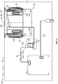
- FIG. 1 shows an example electronic device 100 in accordance with the principles disclosed herein.
- electronic device 100 includes a support base 102, a mounting arm 104 extending from base 102, and a display unit 110 supported on the upper end of arm 104.
- Display unit 110 includes an outer housing 112 and a display screen 114 supported within housing 112.
- Housing 112 includes a rear cover plate 113.
- Cover plate 113 may be removable from the remainder of housing 112 to provide maintenance access inside housing 112, or cover plate 113 may be bonded to or integrally formed with the remainder of housing 112.
- a peripheral module is moveably coupled to housing 112.
- the peripheral module is a camera module 120, and camera module 120 can move vertically up and down relative to housing 112, to retract into housing 112 and to extend from the top surface 122 of housing 112.
- Module 120 can be coupled to housing 112, as shown, or removed from housing 112 while housing 112 remains intact, for example, without removing rear cover plate 113.
- electronic device 100 is an AiO computer.
- a user input device such as a keyboard or mouse, may be coupled to device 100.
- display unit 110 may operate alone, detached from base 102 or arm 104.
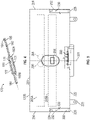
- FIG. 2 shows an inside view of an example display unit 110 with a back cover plate removed and with camera module 120 removed.
- display unit 110 includes an electric connector or image circuit 124, a recess 126 extending from top surface 122, a mounting apparatus 130 disposed within or adjacent recess 126, and a mounting assembly 140 moveably coupled to housing 112 by apparatus 130.
- Mounting assembly 140 is to couple a peripheral module to housing 112 physically and electrically and may also be called a peripheral mounting assembly.
- Image circuit 124 may be a connection board or image processor such as a scalar printed circuit assembly electrically coupled to the mounting assembly 140 with a cable 193 and coupled to the display screen 114 via a cable 125.
- the image circuit 124 may include machine readable instructions that, when executed, cause the image circuit 124 to receive a first set of data from a camera module that is electrically coupled to mounting assembly 140.
- the image circuit 124 may include machine readable instructions that, when executed, cause the image circuit 124 to send a second set of data to the display screen, wherein the second set of data is based on the first set of data.
- mounting apparatus 130 is disposed inside housing 112 and includes a pair of resilient members or springs 132, a pair of shoulders 135, and a pair of stop plates or stops 136. Shoulders 135 are disposed on the lateral sides of recess 126 and mounting apparatus 130.
- Springs 132 bias the mounting assembly 140 toward top surface 122.
- Figure 2 shows the position of mounting assembly 140 in its biased position and without any camera module installed. Thus, the position shown in Figure 2 represents the extended or outward position of mounting assembly 140 with respect to housing 112. The biasing force of springs 132 may pull assembly 140 toward the extended position.
- assembly 140 is contained inside housing 112 or recess 126 with no portion of assembly 140 extending beyond outer surface 122 when mounting assembly 140 is in the extended position. Stops 136 are spaced from top surface 122 sufficiently that mounting assembly 140 may be disposed between outer surface 122 and stops 136 for all position of assembly 140.
- mounting assembly 140 and mounting apparatus 130 form a combined assembly that may be installed or removed from within housing 112 as a combined unit, which may involve removing a rear cover of housing 112 in some examples.
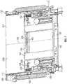
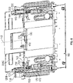
- FIG 3 shows a closer view of an example mounting assembly 140 installed within recess 126 of housing 112 and with assembly 140 in the extended position.
- mounting assembly 140 includes a body 142, a body axis 143 generally passing through a mid-plane of body 142, a pair of latch mechanisms 170, and an electrical interconnect 190.
- Latch mechanisms 170 removably attach a camera module, such as camera module 120 ( Figure 1 ), to mounting assembly 140.
- body 142 includes a top side 144, lateral sides 146, a bottom 147, a plurality of through-apertures 148 extending through top side 144 parallel to body axis 143, and a slot 149 in each lateral side 146.
- a body shoulder 150 is provided along each slot 149 proximal top side 144 and extends toward the body axis 143.
- body 142 includes a pair of elongate mounting slots 152 extending parallel to the body axis 143.
- a pin 154 extends through each slot 152. Pins 154 are fixably coupled to mounting apparatus 130 or housing 112.
- Body 142 is slidably coupled to housing 112 by pins 154 of mounting apparatus 130.
- each latch mechanism 170 includes an elongate latch member 172 extending through an aperture 148 and along a latch axis 171 oriented parallel to body axis 143.
- Latch mechanism 170 is moveably coupled to the camera mounting body 142 and is biased away from top side 144 and into housing 112 by a biasing member, which in this example is a spring 176.
- the example interconnect 190 includes an electrical connector 192 along a top side 144 and a cable 193 to couple electrically the connector 192 and image circuit 124.
- Cable 193 passes through strain relief devices 194 and includes sufficient length to allow the remainder of mounting assembly 140 to move unhindered by cable 193.
- an example latch member 172 includes a slotted portion 180 including an elongate slot 181 extending along axis 171, an arm 182 extending from slotted portion 180, and a leg 186 extending from slotted portion 180.
- Slotted portion 180 has ends 183A; arm 182 extends axially (relative to axis 171) from end 183A, and leg 186 extends axially (relative to axis 171) from end 183B.
- Arm 182 includes a bend 185 such that the upper portion of arm 182 distal slotted portion 180 leans away from body axis 143.
- a shoulder or lip 184 is disposed along arm 182 distal slotted portion 180. Lip 184 extends substantially perpendicular to axis 171 and, in the assembly of Figure 3 , lip 184 extends generally away from body axis 143.
- a pin 174 extends from the camera mounting body 142 into slot 181.
- pin 174 is fixably attached to body 142.
- Pin 174 includes an enlarged head to retain latch member 172.
- Slotted portion180 is disposed within or alongside camera mounting body 142, and arm 182 extends along the direction of axis 171 from camera mounting body 142 beyond top side 144 such that lip 184 is disposed outside body 142.
- latch mechanism 170 is slidably coupled to the camera mounting body 142 by pin 174.
- Spring 176 is coupled between latch member 172 and body 142 to bias latch member 172 away from top surface 122 and into or alongside body 142, which also biases distal end of arm 182 and lip 184 into the recess 126.
- Figure 3 shows this retracted, biased position.
- the distal end of arm 182 and lip 184 may remain inside or return to recess 126 when no camera module is attached due to the action of spring 176 and due to the arrangement of mounting slots 152 and pins 154 that extend through slots 152.
- the distal end of arm 182 and lip 184 may be retained inside recess 126 (e.g., in the biased position) to protect them from damage when no camera module is installed.
- stops 136 of mounting apparatus 130 are aligned with legs 186 of latch mechanism 170 to limit the axial movement (relative to axis 171) of latch member 172 into housing 112. For example, if mounting assembly 140 moves sufficiently downward, then legs 186 may press against stops 136, thereby compressing springs 176 and limiting the distance that arms 182 and lips 184 move downward, away from top surface 122 of housing 112. Limiting the downward movement of arms 182 and lips 184 may aid the installation of a camera module 120 by augmenting the entry of arms 182 into the camera module and providing an opportunity for lips 184 to grasp the module, as will be described in more detail below.
- FIG 5 shows an example of a camera module 120A that is illustrative of camera module 120 of Figure 1 and may be installed in device 100.
- camera module 120A includes a central axis 201, a camera housing 202, a cover plate 204 closing camera housing 202, a first camera 205A mounted inside housing 202, a second camera 205B mounted inside housing 202, and an electrical connector 220.
- camera 205B is spaced apart from camera 205A along axis 201.
- Connector 220 electrically couples to electrical connector 192 of interconnect 190 on mounting assembly 140 ( Figure 2 ).
- Camera module 120A also includes a mounting end 222, a distal end 223, lateral sides 224, a pair of screw tabs 225 extending axially outward from mounting end 222, a pair of second apertures 228, and a pair of internal shoulders 230.
- Each aperture 228 extends through mounting end 222 adjacent one of the lateral sides 224.
- Each shoulder 230 is disposed on one of the lateral sides 224, laterally adjacent to and axially off-set from an aperture 228 and facing distal end 223.
- An aperture 232 extends through each lateral side 224 adjacent each shoulder 230, opposite the aperture 228 that corresponds to the shoulder 230.
- an aperture 228 and a shoulder 230 are to receive an arm 182 and a lip 184, respectively, of a latch mechanism 170 ( Figure 4 ).
- Electrical connector 220 extends axially downward at a mounting end 222.
- first camera 205A includes a pair of camera sensors 206 pointed in a first direction (e.g., into the page of Figure 5 ) through housing 202
- second camera 205B includes a camera sensor 206 pointed in a second direction through cover plate 204 and opposite the first direction.
- Any of camera sensors 206 may be selected from a group that includes sensor types such as: RGB sensors, RGB high definition sensors, infrared (IR) sensors, and other suitable image sensors.
- FIG. 6 shows an example of a camera module 120B that is illustrative of camera module 120 of Figure 1 and may be installed in device 100.
- Camera module 120B is similar or identical to module 120A with an exception that camera module 120B has one camera 205C instead of two cameras.
- camera module 120B includes a central axis 201, a camera housing 202, a cover plate 204, a camera 205C (which may be similar or identical to either camera 205A or 205B) mounted inside housing 202 and cover plate 204, and an electrical connector 220, each as previously described.
- Camera module 120B also includes a mounting end 222, a distal end 223, lateral sides 224, a pair of screw tabs 225 extending outward from mounting end 222, a pair of apertures 228, a pair of internal shoulders 230, and a pair of second apertures 232, arranged as previously described with respect to module 120A.
- each aperture 228 and shoulder 230 is to receive an arm 182 and a lip 184, respectively, of a latch mechanism 170.
- camera 205C includes a camera sensor 206 pointed in a first camera direction (e.g., into the page of Figure 6 ) through housing 202.
- the sensor 206 of module 120A may be selected from any of the type of sensors mentioned above.
- camera 205C is replaced by another camera, such as a camera 205A, 205B.
- the camera modules 120A, 120B have one and two cameras, respectively, in other examples, a camera module compatible with electronic device 100 may have any number of cameras, and further, each camera may have any number of camera sensors.
- FIG 7 and Figure 8 show examples of the camera module 120B installed in electronic device 100 with module 120B coupled to mounting assembly 140 to move with assembly 140 along body axis 143.
- assembly 140 and module 120B are in a recessed position with module 120B entirely or almost fully received within recess 126 of housing 112.
- assembly 140 and module 120B are in a second outward position.
- camera module 120B may move into and out of recess 126 of housing 112 ( Figures 2 and 3 ). This mounted configuration may be achieved by inserting module 120B into recess 126 and by pushing module 120B toward top side 144.
- Latch arms 182 extend through apertures 228 in module 120B.
- lips 184 of arms 182 engage shoulders 230 within module 120B, attaching module 120B to assembly 140 and device 100.
- This engaged arrangement represents a first position for each latch mechanism 170 and its arm 182.
- Latch mechanism 170 is biased to this first position.
- Arm 182 may rest against or press against a boss 236 pointing outward in module 120.
- Bend 185 in arm 182 may be adjacent boss 236 and may be closer to outer surface 122 than boss 236.
- Tabs 225 extend through various apertures 148 in mounting assembly 140, and electrical connector 220 is removably connected with electrical connector 192 of interconnect 190.
- camera module 120B may be installed in housing 112 and coupled to mounting assembly 140 while rear cover plate 113 ( Figure 1 ) is installed on housing 112. Removal of the camera module can likewise be accomplished while rear cover plate 113 is installed on housing 112.
- a camera module 120B may be installed or removed while housing 112 is fully intact, ready for shipment (e.g., held within a shipping box) or ready for a consumer to use.
- a pin, a paperclip, or another type of probe may be inserted into each aperture 232 in lateral sides 224 of module 120B to push each arm 182 and lip 184 away from the adjacent shoulder 230, toward body axis 143.
- This operation moves latch mechanism 170 and its arm 182 to a second position disengaged and spaced-apart from shoulder 230.
- the decoupling of module 120B from assembly 140 may be completed by pulling module 120B away from the inserted arms 182 and top from top side 144, which decouples interconnect 190, removing electrical connector 220 from connector 192.
- the flexible, resilient arms 182 relax, bending away from body axis 143, toward their original shape. With module 120B decoupled, springs 176 will cause arms 182 to retract to a position inside the top surface 122 of housing 112, like the biased position of latch mechanism 170 shown in Figure 3 .
- the easy removal process that involves bending arms 182 to remove a camera module can be prevented by installing a fastener, such as a screw, through one or all tabs 225 and into anchor point(s) in mounting body 142. Installing or removing the fasteners for tabs 225 may involve removing rear cover plate 113 ( Figure 1 ). Preventing the easy removal process may be beneficial when electronic device 100 is used in a public location, and an owner wishes to reduce the potential for people to remove and take a camera module.
- a fastener such as a screw
- arms 182 on the latch mechanism are to engage and dis-engage the camera module 120B from assembly 140.
- Other embodiments of camera module 120 e.g., module 120A, may be coupled and decoupled to assembly 140 in the same manner as module 120B.
- distal end 223 of module 120B may be flush or recessed, with respect to top surface 122 of housing 112. In some recessed positions, distal end 223 may extend slightly beyond top surface 122 of housing 121. Assembly 140 may be near its fully retracted position, with the top of slots 152 almost contacting pins 154.
- assembly 140 and module 120B are in a second outward position in which assembly 140 is not as close to outer surface 112 as it was in the first outward position of Figure 2 and Figure 3 . In the second outward position, a portion of module 120B, including sensor 206 (not shown here) of camera 205C, is outside recess 126. Accordingly, Figure 8 represents an operation position of module 120B because camera 205C is in a location where it can be used to capture images.
- the camera modules disclose herein were mounted to travel through recess 126 extending through top surface 122 of electronic device 100; in some embodiments, a peripheral module attached to a mounting assembly 140 is coupled to move through another surface (for example a side surface or a front surface) in an electronic device.
- Recess 126 has been described as an interior recess in housing 112, but in some examples, a camera module is mounted in accordance with the present disclosure for movement into and out from an exposed recess that extends through the front side or the rear cover plate 113 ( Figure 1 ) of housing 112 in addition to the recess extending though a top surface or a side surface.
- Some examples include microphones in a peripheral module, for example, in a camera module 120, 120A, 120B.
- a pair of microphones is located on distal end 223 of the camera module. In this location, the microphones can face outward even when the camera module is retracted into the housing of an electronic device, such as housing 112.
- This placement may allow machine readable instructions, e.g., software, to activate a voice call or a "digital assistant” like "Siri,” “Alexa,” “Cortana,” etc. while the camera(s) is/are recessed into the housing, to operate the digital assistant with privacy from a camera(s).
- the digital assistant may be activated while the camera is extended beyond the housing.
- microphones 235 may allow them to receive sound from multiple or all sides of the camera module, possibly collecting sound from a volume that spans more than 180 degrees or spans up to or including 360 degrees.
- a camera module may have microphones disposed at another location, such as a side that includes a camera sensor 206.
Landscapes
- Engineering & Computer Science (AREA)
- Theoretical Computer Science (AREA)
- General Engineering & Computer Science (AREA)
- Physics & Mathematics (AREA)
- General Physics & Mathematics (AREA)
- Human Computer Interaction (AREA)
- Computer Hardware Design (AREA)
- Multimedia (AREA)
- Studio Devices (AREA)
Description
- Various electronic devices, such as stand-alone monitors, portable computers, desktop computers, and all-in-one (AiO) desktop computers, include cameras incorporated into the body of the device. For various reasons, the cameras may eventually need to be removed or replaced.
WO 2016/018222 A1 relates to connecting a peripheral device.CN 2870332 Y relates to a device having a concealed camera.US 6,093,044 A relates to a quick connect/disconnect mechanism.US 2015/0029390 A1 relates to a display apparatus. - Various examples are described below referring to the following figures:
-
Figure 1 shows an electronic device having a retractable, removable peripheral module installed in accordance with various examples; -
Figure 2 shows an inside, partially schematic rear view of the electronic display device ofFigure 1 with a rear cover plate removed, showing a mounting assembly for a peripheral module, in accordance with various examples; -
Figure 3 shows an enlarged view of the electronic device ofFigure 2 in accordance with various examples; -
Figure 4 shows the latch mechanism of the electronic device ofFigure 3 in accordance with various examples; -
Figure 5 shows a partial cross-sectional rear view of a camera module for removably attaching to the latch mechanism ofFigure 3 in accordance with various examples; -
Figure 6 shows a partial cross-sectional rear view of another camera module for removably attaching to the latch mechanism ofFigure 3 in accordance with various examples; -
Figure 7 shows a perspective view of the camera module ofFigure 6 installed in the electronic display device ofFigure 1 with the camera module in a recessed position in accordance with various examples; and -
Figure 8 shows a perspective view of the camera module ofFigure 6 installed in the electronic display device ofFigure 1 with the camera module in an operational position in accordance with various examples. - The present invention relates to a device according to the wording of
claim 1. Further aspects and details of the invention are set out in the dependent claims. - In the following discussion and in the claims, the terms "including" and "comprising" are used in an open-ended fashion, and thus should be interpreted to mean "including, but not limited to...." Also, the term "couple" or "couples" is intended to be broad enough to encompass both indirect and direct connections. Thus, if a first device couples to a second device, that connection may be through a direct connection or through an indirect connection via other devices, components, and connections. In addition, as used herein, the terms "axial" and "axially" generally refer to positions along or parallel to a central or longitudinal axis (e.g., central axis of a body or a port), while the terms "lateral" and "laterally" generally refer to positions located or spaced to the side of the central or longitudinal axis.
- As used herein, including in the claims, the word "or" is used in an inclusive manner. For example, "A or B" means any of the following: "A" alone, "B" alone, or both "A" and "B." In addition, when used herein including the claims, the word "generally" or "substantially" means within a range of plus or minus 20% of the stated value.
- Many types of electronic devices include an outer housing and a camera mounted within the outer housing. Accessing the camera often requires the disassembly of the outer housing or at least removing a cover of the outer housing to gain access to the camera. Consequently, installing a camera, removing a camera, or replacing a camera of such electronic devices may be a time consuming and complex process. Examples described herein are directed to apparatuses for removably attaching and detaching peripheral module, such as camera modules that may include a webcam, to and from electronic devices like All-in-One (AiO) computers. In accordance with various examples, the peripheral modules can be installed and removed from the associated electronic devices without removing a cover panel to gain access. To facilitate this objective, this disclosure is directed to examples of electronic devices that include an outer housing, a display screen supported within the outer housing, and a recess in the outer housing that receives movably a peripheral module. A mounting assembly moveably couples the peripheral module to the outer housing and allows the peripheral module to move linearly into and out of the recess. An example mounting assembly includes a latch mechanism that removably attaches to the peripheral module and an electrical interconnect for transferring electrical signals between the webcams and a circuit board or the display screen. The interconnect includes a first electrical connector coupled fixably (e.g., affixed) to the mounting assembly (e.g., moves with the mounting assembly), and the first electrical connector may be connected to a second electrical connector that is coupled fixably to the peripheral module.
- In one example in accordance with the present disclosure, an electronic device comprises an outer housing including a recess to receive a peripheral module. The electronic device also comprises a mounting assembly to move the peripheral module into and out of the recess of the outer housing. The mounting assembly is moveably coupled to the outer housing. The mounting assembly includes a latch mechanism to removably attach the mounting assembly to the peripheral module. In addition, the mounting assembly includes a first electrical connector to removably connect to a second electrical connector of the peripheral module. The latch mechanism includes an arm and a lip disposed along the arm. The arm and a lip are to move into and out of engagement with a shoulder of the peripheral module.
- In some examples, the electronic device comprises a display screen supported by the outer housing.
- In some examples, the mounting assembly includes a body slidably coupled to the outer housing to move along an axis with the peripheral module. The arm of the latch mechanism extends axially from the body and the lip of the latch mechanism is disposed along the arm distal the body. The arm has a first position with the lip positioned to engage the shoulder of the peripheral module to attach the mounting assembly to the peripheral module and a second position with the lip disengaged from the shoulder of the peripheral module to release the peripheral module from the mounting assembly. The arm is biased to the first position.
- In some examples, the latch mechanism comprises a slotted portion coupled to the arm distal the lip and a leg extending axially from the slotted portion opposite the arm. The slotted portion includes an elongate slot oriented parallel to the axis. A pin extends from the body of the mounting assembly into the slot.
- In some examples, the mounting assembly comprises a biasing member to axially bias the lip of the latch mechanism into the recess. The biasing member is axially positioned between the lip and the slotted portion.
- In some examples, the body of the mounting assembly comprises an elongate slot. A pin that is fixably coupled to the outer housing extends through the slot.
- In another example in accordance with the present disclosure, an electronic device comprises an outer housing including a recess to receive a peripheral module and includes a mounting assembly to move the peripheral module into and out of the recess of the outer housing. The mounting assembly includes a body moveably coupled to the outer housing and a latch mechanism moveably coupled to the body. The mounting assembly includes a first electrical connector to connect removably to a second electrical connector of the peripheral module. The latch mechanism includes an arm to engage and dis-engage the peripheral module.
- In some examples, the electronic device comprises a display screen supported by the outer housing, and the first electrical connector is electrically coupled to an image processor disposed in the outer housing. The display screen is electrically coupled to the image processor.
- In some examples, the image processor includes instructions that, when executed, cause the image processor to receive first data from the peripheral module, and cause the image processor to send second data to the display screen. The second data is based on the first data.
- In some examples, a lip extends from the arm. In addition, the arm has a first position with a lip engaging a shoulder of the peripheral module to attach the mounting assembly to the peripheral module and a second position with the lip disengaged from the shoulder of the peripheral module to release the peripheral module from the mounting assembly. The arm is biased to the first position.
- In another example in accordance with the present disclosure, an electronic device comprises an outer housing including a recess extending through an outer surface, a mounting assembly moveably coupled to the outer housing within the recess. In addition, the electronic device includes a peripheral module coupled to the mounting assembly to move with the mounting assembly. Further, the electronic device includes a first electrical connector and a second electrical connector.
- In some examples, the mounting assembly includes a latch mechanism having a first position coupling the peripheral module to the mounting assembly and a second position decoupling the peripheral module from the mounting assembly. The first electrical connector is affixed to the mounting assembly and the second electrical connector is affixed on the peripheral module. The first electrical connector removably engages the second electrical connector.
- In some examples, the mounting assembly includes a body slidably coupled to the outer housing to move along an axis with the peripheral module. The latch mechanism includes an arm extending axially from the body and a lip disposed along the arm distal the body. The lip engages a shoulder of the peripheral module with the latch mechanism in the first position to attach the peripheral module to the latch mechanism. The lip is disengaged from the shoulder of the peripheral module with the latch mechanism in the second position to release the peripheral module from the mounting assembly.
- In some examples, the latch mechanism comprises a slotted portion coupled to an end of the arm distal the lip and a leg extending axially from the slotted portion opposite the arm. The slotted portion includes an elongate slot oriented parallel to the axis. A pin extends from the body of the mounting assembly into the slot of the slotted portion.
- In some examples, the body of the mounting assembly comprises an elongate slot. A pin fixably coupled to the outer housing extends through the slot of the body.
- In some examples, the electronic device comprises a cable coupled electrically between the first electrical connector and an image processor disposed within the outer housing.
-
Figure 1 shows an exampleelectronic device 100 in accordance with the principles disclosed herein. In this example,electronic device 100 includes asupport base 102, a mountingarm 104 extending frombase 102, and adisplay unit 110 supported on the upper end ofarm 104.Display unit 110 includes anouter housing 112 and adisplay screen 114 supported withinhousing 112.Housing 112 includes arear cover plate 113.Cover plate 113 may be removable from the remainder ofhousing 112 to provide maintenance access insidehousing 112, orcover plate 113 may be bonded to or integrally formed with the remainder ofhousing 112. A peripheral module is moveably coupled tohousing 112. In this example, the peripheral module is acamera module 120, andcamera module 120 can move vertically up and down relative tohousing 112, to retract intohousing 112 and to extend from thetop surface 122 ofhousing 112.Module 120 can be coupled tohousing 112, as shown, or removed fromhousing 112 whilehousing 112 remains intact, for example, without removingrear cover plate 113. In the example shown inFigure 1 ,electronic device 100 is an AiO computer. A user input device, such as a keyboard or mouse, may be coupled todevice 100. In some examples,display unit 110 may operate alone, detached frombase 102 orarm 104. -
Figure 2 shows an inside view of anexample display unit 110 with a back cover plate removed and withcamera module 120 removed. In this example, withinhousing 112,display unit 110 includes an electric connector orimage circuit 124, arecess 126 extending fromtop surface 122, a mountingapparatus 130 disposed within oradjacent recess 126, and a mountingassembly 140 moveably coupled tohousing 112 byapparatus 130. Mountingassembly 140 is to couple a peripheral module tohousing 112 physically and electrically and may also be called a peripheral mounting assembly. -
Image circuit 124 may be a connection board or image processor such as a scalar printed circuit assembly electrically coupled to the mountingassembly 140 with acable 193 and coupled to thedisplay screen 114 via acable 125. Theimage circuit 124 may include machine readable instructions that, when executed, cause theimage circuit 124 to receive a first set of data from a camera module that is electrically coupled to mountingassembly 140. Theimage circuit 124 may include machine readable instructions that, when executed, cause theimage circuit 124 to send a second set of data to the display screen, wherein the second set of data is based on the first set of data. - In
Figure 2 , mountingapparatus 130 is disposed insidehousing 112 and includes a pair of resilient members or springs 132, a pair ofshoulders 135, and a pair of stop plates or stops 136.Shoulders 135 are disposed on the lateral sides ofrecess 126 and mountingapparatus 130.Springs 132 bias the mountingassembly 140 towardtop surface 122.Figure 2 shows the position of mountingassembly 140 in its biased position and without any camera module installed. Thus, the position shown inFigure 2 represents the extended or outward position of mountingassembly 140 with respect tohousing 112. The biasing force ofsprings 132 may pull assembly 140 toward the extended position. In this example, some or all ofassembly 140 is contained insidehousing 112 orrecess 126 with no portion ofassembly 140 extending beyondouter surface 122 when mountingassembly 140 is in the extended position.Stops 136 are spaced fromtop surface 122 sufficiently that mountingassembly 140 may be disposed betweenouter surface 122 and stops 136 for all position ofassembly 140. In this example, mountingassembly 140 and mountingapparatus 130 form a combined assembly that may be installed or removed from withinhousing 112 as a combined unit, which may involve removing a rear cover ofhousing 112 in some examples. -
Figure 3 shows a closer view of anexample mounting assembly 140 installed withinrecess 126 ofhousing 112 and withassembly 140 in the extended position. InFigure 3 , mountingassembly 140 includes a body 142, abody axis 143 generally passing through a mid-plane of body 142, a pair oflatch mechanisms 170, and anelectrical interconnect 190.Latch mechanisms 170 removably attach a camera module, such as camera module 120 (Figure 1 ), to mountingassembly 140. - In this example, body 142 includes a
top side 144,lateral sides 146, a bottom 147, a plurality of through-apertures 148 extending throughtop side 144 parallel tobody axis 143, and aslot 149 in eachlateral side 146. Abody shoulder 150 is provided along eachslot 149 proximaltop side 144 and extends toward thebody axis 143. In addition, body 142 includes a pair of elongate mountingslots 152 extending parallel to thebody axis 143. Apin 154 extends through eachslot 152.Pins 154 are fixably coupled to mountingapparatus 130 orhousing 112. Body 142 is slidably coupled tohousing 112 bypins 154 of mountingapparatus 130. - Referring still to
Figure 3 , eachlatch mechanism 170 includes anelongate latch member 172 extending through anaperture 148 and along alatch axis 171 oriented parallel tobody axis 143.Latch mechanism 170 is moveably coupled to the camera mounting body 142 and is biased away fromtop side 144 and intohousing 112 by a biasing member, which in this example is aspring 176. - Referring again to
Figure 2 , theexample interconnect 190 includes anelectrical connector 192 along atop side 144 and acable 193 to couple electrically theconnector 192 andimage circuit 124.Cable 193 passes throughstrain relief devices 194 and includes sufficient length to allow the remainder of mountingassembly 140 to move unhindered bycable 193. - Referring now to
Figure 4 , anexample latch member 172 includes a slottedportion 180 including anelongate slot 181 extending alongaxis 171, anarm 182 extending from slottedportion 180, and aleg 186 extending from slottedportion 180. Slottedportion 180 has ends 183A;arm 182 extends axially (relative to axis 171) from end 183A, andleg 186 extends axially (relative to axis 171) from end 183B.Arm 182 includes a bend 185 such that the upper portion ofarm 182 distal slottedportion 180 leans away frombody axis 143. A shoulder orlip 184 is disposed alongarm 182 distal slottedportion 180.Lip 184 extends substantially perpendicular toaxis 171 and, in the assembly ofFigure 3 ,lip 184 extends generally away frombody axis 143. - As shown in
Figure 3 , apin 174 extends from the camera mounting body 142 intoslot 181. In this example, pin 174 is fixably attached to body 142.Pin 174 includes an enlarged head to retainlatch member 172. Slotted portion180 is disposed within or alongside camera mounting body 142, andarm 182 extends along the direction ofaxis 171 from camera mounting body 142 beyondtop side 144 such thatlip 184 is disposed outside body 142. Thus,latch mechanism 170 is slidably coupled to the camera mounting body 142 bypin 174. -
Spring 176 is coupled betweenlatch member 172 and body 142 to biaslatch member 172 away fromtop surface 122 and into or alongside body 142, which also biases distal end ofarm 182 andlip 184 into therecess 126.Figure 3 shows this retracted, biased position. The distal end ofarm 182 andlip 184 may remain inside or return to recess 126 when no camera module is attached due to the action ofspring 176 and due to the arrangement of mountingslots 152 and pins 154 that extend throughslots 152. The distal end ofarm 182 andlip 184 may be retained inside recess 126 (e.g., in the biased position) to protect them from damage when no camera module is installed. - As shown in
Figure 3 , stops 136 of mountingapparatus 130 are aligned withlegs 186 oflatch mechanism 170 to limit the axial movement (relative to axis 171) oflatch member 172 intohousing 112. For example, if mountingassembly 140 moves sufficiently downward, thenlegs 186 may press againststops 136, thereby compressingsprings 176 and limiting the distance thatarms 182 andlips 184 move downward, away fromtop surface 122 ofhousing 112. Limiting the downward movement ofarms 182 andlips 184 may aid the installation of acamera module 120 by augmenting the entry ofarms 182 into the camera module and providing an opportunity forlips 184 to grasp the module, as will be described in more detail below. -
Figure 5 shows an example of a camera module 120A that is illustrative ofcamera module 120 ofFigure 1 and may be installed indevice 100. InFigure 5 , camera module 120A includes acentral axis 201, acamera housing 202, acover plate 204closing camera housing 202, a first camera 205A mounted insidehousing 202, a second camera 205B mounted insidehousing 202, and anelectrical connector 220. In this example, camera 205B is spaced apart from camera 205A alongaxis 201.Connector 220 electrically couples toelectrical connector 192 ofinterconnect 190 on mounting assembly 140 (Figure 2 ). Camera module 120A also includes a mountingend 222, adistal end 223,lateral sides 224, a pair ofscrew tabs 225 extending axially outward from mountingend 222, a pair ofsecond apertures 228, and a pair ofinternal shoulders 230. Eachaperture 228 extends through mountingend 222 adjacent one of the lateral sides 224. Eachshoulder 230 is disposed on one of thelateral sides 224, laterally adjacent to and axially off-set from anaperture 228 and facingdistal end 223. Anaperture 232 extends through eachlateral side 224 adjacent eachshoulder 230, opposite theaperture 228 that corresponds to theshoulder 230. Near eachlateral side 224, anaperture 228 and ashoulder 230 are to receive anarm 182 and alip 184, respectively, of a latch mechanism 170 (Figure 4 ).Electrical connector 220 extends axially downward at a mountingend 222. - In camera module 120A, first camera 205A includes a pair of
camera sensors 206 pointed in a first direction (e.g., into the page ofFigure 5 ) throughhousing 202, and second camera 205B includes acamera sensor 206 pointed in a second direction throughcover plate 204 and opposite the first direction. Any ofcamera sensors 206 may be selected from a group that includes sensor types such as: RGB sensors, RGB high definition sensors, infrared (IR) sensors, and other suitable image sensors. -
Figure 6 shows an example of acamera module 120B that is illustrative ofcamera module 120 ofFigure 1 and may be installed indevice 100.Camera module 120B is similar or identical to module 120A with an exception thatcamera module 120B has onecamera 205C instead of two cameras. In particular,camera module 120B includes acentral axis 201, acamera housing 202, acover plate 204, acamera 205C (which may be similar or identical to either camera 205A or 205B) mounted insidehousing 202 andcover plate 204, and anelectrical connector 220, each as previously described.Camera module 120B also includes a mountingend 222, adistal end 223,lateral sides 224, a pair ofscrew tabs 225 extending outward from mountingend 222, a pair ofapertures 228, a pair ofinternal shoulders 230, and a pair ofsecond apertures 232, arranged as previously described with respect to module 120A. Again, eachaperture 228 andshoulder 230 is to receive anarm 182 and alip 184, respectively, of alatch mechanism 170. - In
camera module 120B,camera 205C includes acamera sensor 206 pointed in a first camera direction (e.g., into the page ofFigure 6 ) throughhousing 202. Thesensor 206 of module 120A may be selected from any of the type of sensors mentioned above. In some examples ofmodule 120B,camera 205C is replaced by another camera, such as a camera 205A, 205B. Although thecamera modules 120A, 120B have one and two cameras, respectively, in other examples, a camera module compatible withelectronic device 100 may have any number of cameras, and further, each camera may have any number of camera sensors. -
Figure 7 andFigure 8 show examples of thecamera module 120B installed inelectronic device 100 withmodule 120B coupled to mountingassembly 140 to move withassembly 140 alongbody axis 143. InFigure 7 ,assembly 140 andmodule 120B are in a recessed position withmodule 120B entirely or almost fully received withinrecess 126 ofhousing 112. InFigure 8 ,assembly 140 andmodule 120B are in a second outward position. When mounted toassembly 140 as shown in these two figures,camera module 120B may move into and out ofrecess 126 of housing 112 (Figures 2 and3 ). This mounted configuration may be achieved by insertingmodule 120B intorecess 126 and by pushingmodule 120B towardtop side 144. Latcharms 182 extend throughapertures 228 inmodule 120B. As shown inFigure 8 ,lips 184 ofarms 182 engageshoulders 230 withinmodule 120B, attachingmodule 120B toassembly 140 anddevice 100. This engaged arrangement represents a first position for eachlatch mechanism 170 and itsarm 182.Latch mechanism 170 is biased to this first position.Arm 182 may rest against or press against aboss 236 pointing outward inmodule 120. Bend 185 inarm 182 may beadjacent boss 236 and may be closer toouter surface 122 thanboss 236.Tabs 225 extend throughvarious apertures 148 in mountingassembly 140, andelectrical connector 220 is removably connected withelectrical connector 192 ofinterconnect 190. Although,housing 112 is shown without a rear cover plate for clarity during this discussion ofFigures 7 and8 , in general,camera module 120B may be installed inhousing 112 and coupled to mountingassembly 140 while rear cover plate 113 (Figure 1 ) is installed onhousing 112. Removal of the camera module can likewise be accomplished whilerear cover plate 113 is installed onhousing 112. In a related example, acamera module 120B may be installed or removed whilehousing 112 is fully intact, ready for shipment (e.g., held within a shipping box) or ready for a consumer to use. - Referring still to
Figure 8 , to removecamera module 120B from mountingassembly 140 ordevice 100, a pin, a paperclip, or another type of probe (not shown) may be inserted into eachaperture 232 inlateral sides 224 ofmodule 120B to push eacharm 182 andlip 184 away from theadjacent shoulder 230, towardbody axis 143. This operation moveslatch mechanism 170 and itsarm 182 to a second position disengaged and spaced-apart fromshoulder 230. The decoupling ofmodule 120B fromassembly 140 may be completed by pullingmodule 120B away from the insertedarms 182 and top fromtop side 144, which decouplesinterconnect 190, removingelectrical connector 220 fromconnector 192. The flexible,resilient arms 182 relax, bending away frombody axis 143, toward their original shape. Withmodule 120B decoupled, springs 176 will causearms 182 to retract to a position inside thetop surface 122 ofhousing 112, like the biased position oflatch mechanism 170 shown inFigure 3 . - The easy removal process that involves bending
arms 182 to remove a camera module can be prevented by installing a fastener, such as a screw, through one or alltabs 225 and into anchor point(s) in mounting body 142. Installing or removing the fasteners fortabs 225 may involve removing rear cover plate 113 (Figure 1 ). Preventing the easy removal process may be beneficial whenelectronic device 100 is used in a public location, and an owner wishes to reduce the potential for people to remove and take a camera module. - In the manner described,
arms 182 on the latch mechanism are to engage and dis-engage thecamera module 120B fromassembly 140. Other embodiments ofcamera module 120, e.g., module 120A, may be coupled and decoupled toassembly 140 in the same manner asmodule 120B. - Referring to the recessed position of
assembly 140 andmodule 120B shown inFigure 7 ,distal end 223 ofmodule 120B may be flush or recessed, with respect totop surface 122 ofhousing 112. In some recessed positions,distal end 223 may extend slightly beyondtop surface 122 of housing 121.Assembly 140 may be near its fully retracted position, with the top ofslots 152 almost contactingpins 154. InFigure 8 ,assembly 140 andmodule 120B are in a second outward position in whichassembly 140 is not as close toouter surface 112 as it was in the first outward position ofFigure 2 andFigure 3 . In the second outward position, a portion ofmodule 120B, including sensor 206 (not shown here) ofcamera 205C, isoutside recess 126. Accordingly,Figure 8 represents an operation position ofmodule 120B becausecamera 205C is in a location where it can be used to capture images. - Although, the camera modules disclose herein were mounted to travel through
recess 126 extending throughtop surface 122 ofelectronic device 100; in some embodiments, a peripheral module attached to a mountingassembly 140 is coupled to move through another surface (for example a side surface or a front surface) in an electronic device.Recess 126 has been described as an interior recess inhousing 112, but in some examples, a camera module is mounted in accordance with the present disclosure for movement into and out from an exposed recess that extends through the front side or the rear cover plate 113 (Figure 1 ) ofhousing 112 in addition to the recess extending though a top surface or a side surface. - Some examples include microphones in a peripheral module, for example, in a
camera module distal end 223 of the camera module. In this location, the microphones can face outward even when the camera module is retracted into the housing of an electronic device, such ashousing 112. This placement may allow machine readable instructions, e.g., software, to activate a voice call or a "digital assistant" like "Siri," "Alexa," "Cortana," etc. while the camera(s) is/are recessed into the housing, to operate the digital assistant with privacy from a camera(s). In other instances, the digital assistant may be activated while the camera is extended beyond the housing. The outward placement of microphones 235 may allow them to receive sound from multiple or all sides of the camera module, possibly collecting sound from a volume that spans more than 180 degrees or spans up to or including 360 degrees. Some other examples, a camera module may have microphones disposed at another location, such as a side that includes acamera sensor 206. - The above discussion is meant to be illustrative of the principles and various examples of the present disclosure. Numerous variations and modifications to the examples described above are possible. example, although various examples of the electronic devices disclosed may be implemented as AiO computers or within AiO computers, the concepts described herein may also be applied to other electronic devices, such as other desktop computers, stand-alone monitors, and portable computers (including "tablet" and "laptop" computers), as examples.
Claims (15)
- An electronic device (100) comprising:an outer housing (112) including a recess (126) to receive a peripheral module (120, 120B); anda mounting assembly (140) to move the peripheral module into and out of the recess of the outer housing, wherein the mounting assembly is moveably coupled to the outer housing;wherein the mounting assembly includes a latch mechanism (170) to removably attach the mounting assembly to the peripheral module;wherein the mounting assembly includes a first electrical connector (192) to removably connect to a second electrical connector (220) of the peripheral module; characterized in that:the latch mechanism includes an arm (182) and a lip (184) disposed along the arm;the arm and a lip are to move into and out of engagement with a shoulder (230) of the peripheral module; andthe latch mechanism is biased into the outer housing (112)
- The electronic device (100) of claim 1 comprising a display screen (114) supported by the outer housing (112).
- The electronic device (100) of claim 1, wherein the mounting assembly (140) includes a body slidably coupled to the outer housing (112) to move along an axis with the peripheral module (120, 120B);wherein the arm (182) of the latch mechanism (170) extends axially from the body and the lip (184) of the latch mechanism is disposed along the arm distal the body;wherein the arm has a first position with the lip positioned to engage the shoulder (230) of the peripheral module to attach the mounting assembly to the peripheral module, wherein the arm has a second position with the lip disengaged from the shoulder of the peripheral module to release the peripheral module from the mounting assembly, wherein the arm is biased to the first position.
- The electronic device (100) of claim 3, wherein the latch mechanism (170) comprises:a slotted portion (180) coupled to the arm (182) distal the lip (184); anda leg extending axially from the slotted portion opposite the arm;wherein the slotted portion includes an elongate slot (181) oriented parallel to the axis;wherein a pin (174) extends from the body of the mounting assembly (140) into the slot.
- The electronic device (100) of claim 3, wherein the mounting assembly (140) comprises a biasing member to axially bias the lip of the latch mechanism (170) into the recess (126), wherein the biasing member is axially positioned between the lip and the slotted portion (180).
- The electronic device (100) of claim 3, wherein the body of the mounting assembly (140) comprises an elongate slot (181), and wherein a pin (174) fixably coupled to the outer housing (112) extends through the slot.
- The electronic device (100) of claim 1, wherein the mounting assembly (140) includes a body moveably coupled to the outer housing (112) and wherein the latch mechanism (170) is moveably coupled to the body.
- The electronic device (100) of claim 7 comprising a display screen (114) supported by the outer housing (112);
wherein the first electrical connector (192) is electrically coupled to an image processor disposed in the outer housing, wherein the display screen is electrically coupled to the image processor. - The electronic device (100) of claim 8, wherein the image processor includes instructions that, when executed, cause the image processor to receive first data from the peripheral module (120, 120B);
wherein the image processor includes instructions that, when executed, cause the image processor to send second data to the display screen (114), wherein the second data is based on the first data. - The electronic device (100) of claim 7, wherein a lip (184) extends from the arm (182); and
wherein the arm has a first position with a lip engaging a shoulder (230) of the peripheral module (120, 120B) to attach the mounting assembly (140) to the peripheral module and a second position with the lip disengaged from the shoulder of the peripheral module to release the peripheral module from the mounting assembly, wherein the arm is biased to the first position. - The electronic device (100) of claim 1, comprising:a peripheral module (120, 120B) coupled to the mounting assembly (140) to move with the mounting assembly, wherein the latch mechanism (170) has a first position coupling the peripheral module to the mounting assembly and a second position decoupling the peripheral module from the mounting assembly;wherein the first electrical connector (192) is affixed to the mounting assembly;wherein the second electrical connector (220) is affixed on the peripheral module; andwherein the first electrical connector removably engages the second electrical connector.
- The electronic device (100) of claim 11, wherein the mounting assembly (140) includes a body slidably coupled to the outer housing (112) to move along an axis with the peripheral module (120, 120B);wherein the latch mechanism (170) includes an arm (182) extending axially from the body and a lip (184) disposed along the arm distal the body;wherein the lip engages a shoulder (230) of the peripheral module with the latch mechanism in the first position to attach the peripheral module to the latch mechanism, and the lip is disengaged from the shoulder of the peripheral module with the latch mechanism in the second position to release the peripheral module from the mounting assembly.
- The electronic device (100) of claim 12, wherein the latch mechanism (170) comprises:a slotted portion (180) coupled to an end of the arm (182) distal the lip (184); anda leg extending axially from the slotted portion opposite the arm;wherein the slotted portion includes an elongate slot (181) oriented parallel to the axis;wherein a pin (174) extends from the body of the mounting assembly (140) into the slot of the slotted portion.
- The electronic device (100) of claim 13, wherein the body of the mounting assembly (140) comprises the elongate slot (181), and wherein the pin is fixably coupled to the outer housing (112) extends through the slot of the body.
- The electronic device (100) of claim 11 comprising a cable coupled electrically between the first electrical connector (192) and an image processor disposed within the outer housing (112).
Applications Claiming Priority (1)
| Application Number | Priority Date | Filing Date | Title |
|---|---|---|---|
| PCT/US2017/040938 WO2019009907A1 (en) | 2017-07-06 | 2017-07-06 | Mounting assemblies for peripheral modules |
Publications (3)
| Publication Number | Publication Date |
|---|---|
| EP3649836A1 EP3649836A1 (en) | 2020-05-13 |
| EP3649836A4 EP3649836A4 (en) | 2021-03-10 |
| EP3649836B1 true EP3649836B1 (en) | 2022-06-08 |
Family
ID=64950305
Family Applications (1)
| Application Number | Title | Priority Date | Filing Date |
|---|---|---|---|
| EP17917195.4A Active EP3649836B1 (en) | 2017-07-06 | 2017-07-06 | Mounting assemblies for peripheral modules |
Country Status (4)
| Country | Link |
|---|---|
| US (1) | US11360506B2 (en) |
| EP (1) | EP3649836B1 (en) |
| CN (1) | CN111034377B (en) |
| WO (1) | WO2019009907A1 (en) |
Families Citing this family (9)
| Publication number | Priority date | Publication date | Assignee | Title |
|---|---|---|---|---|
| US11402878B2 (en) * | 2018-11-01 | 2022-08-02 | Lg Electronics Inc. | Display device |
| USD982539S1 (en) * | 2020-09-17 | 2023-04-04 | Lg Electronics Inc. | Television receiver |
| USD981357S1 (en) * | 2020-10-14 | 2023-03-21 | Lg Electronics Inc. | Television receiver |
| JP1716365S (en) * | 2021-03-15 | 2022-05-31 | television | |
| CN116045174B (en) * | 2021-10-28 | 2025-07-25 | 纬联电子科技(中山)有限公司 | Display device, electronic device and telescopic assembly |
| USD988320S1 (en) * | 2021-12-07 | 2023-06-06 | Lg Electronics Inc. | Monitor for computer |
| USD988319S1 (en) * | 2021-12-22 | 2023-06-06 | Lg Electronics Inc. | Monitor for computer |
| CN117469528A (en) * | 2022-07-22 | 2024-01-30 | 纬创资通(中山)有限公司 | Base mechanism and electronic device peripheral components and electronic devices including the same |
| USD1038125S1 (en) * | 2022-09-16 | 2024-08-06 | Jupiter Systems, Inc. | Display screen |
Family Cites Families (33)
| Publication number | Priority date | Publication date | Assignee | Title |
|---|---|---|---|---|
| US5014136A (en) | 1987-10-29 | 1991-05-07 | Asahi Kogaku Kogyo Kabushiki Kaisha | Electronic still camera device |
| US5521369A (en) | 1994-07-25 | 1996-05-28 | Khyber Technologies Corporation | Card shaped computer peripheral device |
| US5959671A (en) | 1995-09-14 | 1999-09-28 | Canon Kabushiki Kaisha | Adapter system for connection and disconnection of peripheral equipment with an electric apparatus and having a cam system |
| TW352206U (en) | 1997-12-30 | 1999-02-01 | First Int Computer Inc | Structure for hidden type image picking apparatus of notebook computer |
| US6093044A (en) * | 1998-04-16 | 2000-07-25 | Pelco | Quick connect/disconnect mechanism |
| JPH11313233A (en) | 1998-04-28 | 1999-11-09 | Kyocera Corp | Digital camera system that can be integrated with an auxiliary storage device |
| US6812958B1 (en) * | 1998-09-10 | 2004-11-02 | Intel Corporation | Storable digital camera associated with a computer system |
| KR100621606B1 (en) * | 1998-12-03 | 2006-11-30 | 삼성전자주식회사 | A portable computer |
| JP3725460B2 (en) | 2000-10-06 | 2005-12-14 | 株式会社ソニー・コンピュータエンタテインメント | Image processing apparatus, image processing method, recording medium, computer program, semiconductor device |
| ES2267697T3 (en) | 2000-10-13 | 2007-03-16 | Lg Electronics Inc. | APPARATUS TO AUTOMATICALLY ADJUST THE ANGLE OF AN IMAGE TAKING DEVICE. |
| JP2004088738A (en) | 2002-07-04 | 2004-03-18 | Sharp Corp | Image display device having connection unit for image input unit and image input unit thereof |
| ES2284360B1 (en) | 2005-11-14 | 2008-09-01 | Telefonica, S.A. | CLOSURE DEVICE FOR ARCHES OF PUBLIC TELEPHONES. |
| CN2870332Y (en) * | 2005-12-29 | 2007-02-14 | 英业达股份有限公司 | A hidden camera device |
| US8854441B2 (en) | 2006-02-10 | 2014-10-07 | Freedom Scientific, Inc. | Electronic magnification device |
| US20080013262A1 (en) | 2006-06-30 | 2008-01-17 | Logitech Europe S.A. | Computer monitor with detachable module |
| TW200823675A (en) * | 2006-11-22 | 2008-06-01 | Acer Inc | Laptop computer with replaceable camera module |
| US20080166898A1 (en) | 2007-01-05 | 2008-07-10 | Jonathan Hubert | Method of making an expandable and collapsible peripheral device |
| TW200836611A (en) | 2007-02-16 | 2008-09-01 | Acer Inc | Opening structure for portable device |
| TW201007433A (en) | 2008-08-12 | 2010-02-16 | Asustek Comp Inc | Portable computer |
| TWM361204U (en) * | 2008-11-18 | 2009-07-11 | Wistron Corp | Electronic device |
| TWI387429B (en) | 2009-08-25 | 2013-02-21 | Wistron Corp | Portable electronic system with a detachable camera module |
| CN102789265A (en) | 2011-05-18 | 2012-11-21 | 鸿富锦精密工业(深圳)有限公司 | Electronic device |
| CN102957763A (en) | 2011-08-18 | 2013-03-06 | 希姆通信息技术(上海)有限公司 | Mobile phone |
| CN103517593B (en) | 2012-06-21 | 2017-08-01 | 富泰华工业(深圳)有限公司 | Electronic device with access mechanism |
| KR101947572B1 (en) | 2012-07-06 | 2019-02-14 | 삼성전자 주식회사 | Display apparatus and control method thereof |
| CN105308534B (en) | 2013-06-11 | 2018-11-02 | Invue安全产品公司 | Anti-theft device for portable electronic devices |
| KR20150014336A (en) * | 2013-07-29 | 2015-02-06 | 삼성전자주식회사 | Display apparatus |
| CN104571271B (en) | 2013-10-11 | 2018-01-02 | 和硕联合科技股份有限公司 | electronic device |
| CN104902717B (en) | 2014-03-04 | 2018-03-20 | 鸿富锦精密工业(深圳)有限公司 | Cover plate opening and closing structure |
| WO2016018222A1 (en) * | 2014-07-28 | 2016-02-04 | Hewlett-Packard Development Company, L.P. | Connecting a peripheral device |
| CN204217258U (en) | 2014-10-31 | 2015-03-18 | 深圳市理邦精密仪器股份有限公司 | A kind of easy-to-mount socket type structural and there are its Medical Devices |
| EP3104250A1 (en) | 2015-06-10 | 2016-12-14 | FairPhone B.V. | Modular electronic device |
| CN105141815B (en) | 2015-09-02 | 2018-07-31 | 小米科技有限责任公司 | Camera automatic pop-up device and terminal |
-
2017
- 2017-07-06 EP EP17917195.4A patent/EP3649836B1/en active Active
- 2017-07-06 US US16/075,598 patent/US11360506B2/en active Active
- 2017-07-06 CN CN201780094670.6A patent/CN111034377B/en active Active
- 2017-07-06 WO PCT/US2017/040938 patent/WO2019009907A1/en not_active Ceased
Also Published As
| Publication number | Publication date |
|---|---|
| CN111034377B (en) | 2021-09-03 |
| US20200209914A1 (en) | 2020-07-02 |
| EP3649836A1 (en) | 2020-05-13 |
| US11360506B2 (en) | 2022-06-14 |
| CN111034377A (en) | 2020-04-17 |
| EP3649836A4 (en) | 2021-03-10 |
| WO2019009907A1 (en) | 2019-01-10 |
Similar Documents
| Publication | Publication Date | Title |
|---|---|---|
| EP3649836B1 (en) | Mounting assemblies for peripheral modules | |
| US11150690B2 (en) | Movable mounting assemblies | |
| US8986023B2 (en) | Slim type electronic connector and electronic device having the same | |
| US12585607B2 (en) | Bus module and server | |
| TWI475394B (en) | Transmission port module for expanding transmission capacity of a host module and computer system therwith | |
| US11126230B1 (en) | Mechanism for securing and docking an adapter card in a computer chassis | |
| US7630212B2 (en) | Handle for a riser card assembly | |
| US7399196B2 (en) | Interface card fixing member | |
| TWI592789B (en) | Connecting a peripheral device | |
| US9538682B1 (en) | Strengthening electronic equipment | |
| US20070153492A1 (en) | Expansion card mounting apparatus | |
| US8027159B2 (en) | Fixing mechanism for fixing a removable module of an electronic device | |
| CN105717985A (en) | Integrated computer | |
| US20100259894A1 (en) | Electronic device with expansion card fasterning device | |
| WO2026001880A1 (en) | Fixing structure of circuit board and case | |
| US20130112825A1 (en) | Expansion card retaining structure | |
| US7315446B2 (en) | Hard drive connecting device for notebook computer | |
| US7562915B2 (en) | Fastening mechanism | |
| US8941984B2 (en) | Storage bridge bay canister attachment system and method of forming same | |
| US20110188190A1 (en) | Electronic apparatus having replaceable input device | |
| US8199497B2 (en) | Electronic device enclosure and electronic device | |
| US20160112591A1 (en) | Formatter cage | |
| JP5245371B2 (en) | Internal mechanism drawer type instrument | |
| US7403398B2 (en) | Positioning member for securing in position add-on board | |
| TW201129282A (en) | Computer case |
Legal Events
| Date | Code | Title | Description |
|---|---|---|---|
| STAA | Information on the status of an ep patent application or granted ep patent |
Free format text: STATUS: THE INTERNATIONAL PUBLICATION HAS BEEN MADE |
|
| PUAI | Public reference made under article 153(3) epc to a published international application that has entered the european phase |
Free format text: ORIGINAL CODE: 0009012 |
|
| STAA | Information on the status of an ep patent application or granted ep patent |
Free format text: STATUS: REQUEST FOR EXAMINATION WAS MADE |
|
| 17P | Request for examination filed |
Effective date: 20191223 |
|
| AK | Designated contracting states |
Kind code of ref document: A1 Designated state(s): AL AT BE BG CH CY CZ DE DK EE ES FI FR GB GR HR HU IE IS IT LI LT LU LV MC MK MT NL NO PL PT RO RS SE SI SK SM TR |
|
| AX | Request for extension of the european patent |
Extension state: BA ME |
|
| DAV | Request for validation of the european patent (deleted) | ||
| DAX | Request for extension of the european patent (deleted) | ||
| A4 | Supplementary search report drawn up and despatched |
Effective date: 20210205 |
|
| RIC1 | Information provided on ipc code assigned before grant |
Ipc: H05K 5/02 20060101AFI20210201BHEP |
|
| REG | Reference to a national code |
Ref country code: DE Ref legal event code: R079 Ref document number: 602017058432 Country of ref document: DE Free format text: PREVIOUS MAIN CLASS: H05K0005020000 Ipc: G06F0001160000 |
|
| GRAP | Despatch of communication of intention to grant a patent |
Free format text: ORIGINAL CODE: EPIDOSNIGR1 |
|
| STAA | Information on the status of an ep patent application or granted ep patent |
Free format text: STATUS: GRANT OF PATENT IS INTENDED |
|
| RIC1 | Information provided on ipc code assigned before grant |
Ipc: H04M 1/02 20060101ALI20220118BHEP Ipc: G06F 1/16 20060101AFI20220118BHEP |
|
| INTG | Intention to grant announced |
Effective date: 20220215 |
|
| GRAS | Grant fee paid |
Free format text: ORIGINAL CODE: EPIDOSNIGR3 |
|
| GRAA | (expected) grant |
Free format text: ORIGINAL CODE: 0009210 |
|
| STAA | Information on the status of an ep patent application or granted ep patent |
Free format text: STATUS: THE PATENT HAS BEEN GRANTED |
|
| AK | Designated contracting states |
Kind code of ref document: B1 Designated state(s): AL AT BE BG CH CY CZ DE DK EE ES FI FR GB GR HR HU IE IS IT LI LT LU LV MC MK MT NL NO PL PT RO RS SE SI SK SM TR |
|
| REG | Reference to a national code |
Ref country code: AT Ref legal event code: REF Ref document number: 1497369 Country of ref document: AT Kind code of ref document: T Effective date: 20220615 Ref country code: CH Ref legal event code: EP |
|
| REG | Reference to a national code |
Ref country code: DE Ref legal event code: R096 Ref document number: 602017058432 Country of ref document: DE |
|
| REG | Reference to a national code |
Ref country code: IE Ref legal event code: FG4D |
|
| REG | Reference to a national code |
Ref country code: LT Ref legal event code: MG9D |
|
| REG | Reference to a national code |
Ref country code: NL Ref legal event code: MP Effective date: 20220608 |
|
| PG25 | Lapsed in a contracting state [announced via postgrant information from national office to epo] |
Ref country code: SE Free format text: LAPSE BECAUSE OF FAILURE TO SUBMIT A TRANSLATION OF THE DESCRIPTION OR TO PAY THE FEE WITHIN THE PRESCRIBED TIME-LIMIT Effective date: 20220608 Ref country code: NO Free format text: LAPSE BECAUSE OF FAILURE TO SUBMIT A TRANSLATION OF THE DESCRIPTION OR TO PAY THE FEE WITHIN THE PRESCRIBED TIME-LIMIT Effective date: 20220908 Ref country code: LT Free format text: LAPSE BECAUSE OF FAILURE TO SUBMIT A TRANSLATION OF THE DESCRIPTION OR TO PAY THE FEE WITHIN THE PRESCRIBED TIME-LIMIT Effective date: 20220608 Ref country code: HR Free format text: LAPSE BECAUSE OF FAILURE TO SUBMIT A TRANSLATION OF THE DESCRIPTION OR TO PAY THE FEE WITHIN THE PRESCRIBED TIME-LIMIT Effective date: 20220608 Ref country code: GR Free format text: LAPSE BECAUSE OF FAILURE TO SUBMIT A TRANSLATION OF THE DESCRIPTION OR TO PAY THE FEE WITHIN THE PRESCRIBED TIME-LIMIT Effective date: 20220909 Ref country code: FI Free format text: LAPSE BECAUSE OF FAILURE TO SUBMIT A TRANSLATION OF THE DESCRIPTION OR TO PAY THE FEE WITHIN THE PRESCRIBED TIME-LIMIT Effective date: 20220608 Ref country code: ES Free format text: LAPSE BECAUSE OF FAILURE TO SUBMIT A TRANSLATION OF THE DESCRIPTION OR TO PAY THE FEE WITHIN THE PRESCRIBED TIME-LIMIT Effective date: 20220608 Ref country code: BG Free format text: LAPSE BECAUSE OF FAILURE TO SUBMIT A TRANSLATION OF THE DESCRIPTION OR TO PAY THE FEE WITHIN THE PRESCRIBED TIME-LIMIT Effective date: 20220908 |
|
| REG | Reference to a national code |
Ref country code: AT Ref legal event code: MK05 Ref document number: 1497369 Country of ref document: AT Kind code of ref document: T Effective date: 20220608 |
|
| PG25 | Lapsed in a contracting state [announced via postgrant information from national office to epo] |
Ref country code: RS Free format text: LAPSE BECAUSE OF FAILURE TO SUBMIT A TRANSLATION OF THE DESCRIPTION OR TO PAY THE FEE WITHIN THE PRESCRIBED TIME-LIMIT Effective date: 20220608 Ref country code: LV Free format text: LAPSE BECAUSE OF FAILURE TO SUBMIT A TRANSLATION OF THE DESCRIPTION OR TO PAY THE FEE WITHIN THE PRESCRIBED TIME-LIMIT Effective date: 20220608 |
|
| PG25 | Lapsed in a contracting state [announced via postgrant information from national office to epo] |
Ref country code: NL Free format text: LAPSE BECAUSE OF FAILURE TO SUBMIT A TRANSLATION OF THE DESCRIPTION OR TO PAY THE FEE WITHIN THE PRESCRIBED TIME-LIMIT Effective date: 20220608 |
|
| PG25 | Lapsed in a contracting state [announced via postgrant information from national office to epo] |
Ref country code: SM Free format text: LAPSE BECAUSE OF FAILURE TO SUBMIT A TRANSLATION OF THE DESCRIPTION OR TO PAY THE FEE WITHIN THE PRESCRIBED TIME-LIMIT Effective date: 20220608 Ref country code: SK Free format text: LAPSE BECAUSE OF FAILURE TO SUBMIT A TRANSLATION OF THE DESCRIPTION OR TO PAY THE FEE WITHIN THE PRESCRIBED TIME-LIMIT Effective date: 20220608 Ref country code: RO Free format text: LAPSE BECAUSE OF FAILURE TO SUBMIT A TRANSLATION OF THE DESCRIPTION OR TO PAY THE FEE WITHIN THE PRESCRIBED TIME-LIMIT Effective date: 20220608 Ref country code: PT Free format text: LAPSE BECAUSE OF FAILURE TO SUBMIT A TRANSLATION OF THE DESCRIPTION OR TO PAY THE FEE WITHIN THE PRESCRIBED TIME-LIMIT Effective date: 20221010 Ref country code: EE Free format text: LAPSE BECAUSE OF FAILURE TO SUBMIT A TRANSLATION OF THE DESCRIPTION OR TO PAY THE FEE WITHIN THE PRESCRIBED TIME-LIMIT Effective date: 20220608 Ref country code: CZ Free format text: LAPSE BECAUSE OF FAILURE TO SUBMIT A TRANSLATION OF THE DESCRIPTION OR TO PAY THE FEE WITHIN THE PRESCRIBED TIME-LIMIT Effective date: 20220608 Ref country code: AT Free format text: LAPSE BECAUSE OF FAILURE TO SUBMIT A TRANSLATION OF THE DESCRIPTION OR TO PAY THE FEE WITHIN THE PRESCRIBED TIME-LIMIT Effective date: 20220608 |
|
| PG25 | Lapsed in a contracting state [announced via postgrant information from national office to epo] |
Ref country code: PL Free format text: LAPSE BECAUSE OF FAILURE TO SUBMIT A TRANSLATION OF THE DESCRIPTION OR TO PAY THE FEE WITHIN THE PRESCRIBED TIME-LIMIT Effective date: 20220608 Ref country code: IS Free format text: LAPSE BECAUSE OF FAILURE TO SUBMIT A TRANSLATION OF THE DESCRIPTION OR TO PAY THE FEE WITHIN THE PRESCRIBED TIME-LIMIT Effective date: 20221008 |
|
| REG | Reference to a national code |
Ref country code: CH Ref legal event code: PL |
|
| REG | Reference to a national code |
Ref country code: DE Ref legal event code: R097 Ref document number: 602017058432 Country of ref document: DE |
|
| REG | Reference to a national code |
Ref country code: BE Ref legal event code: MM Effective date: 20220731 |
|
| PG25 | Lapsed in a contracting state [announced via postgrant information from national office to epo] |
Ref country code: MC Free format text: LAPSE BECAUSE OF FAILURE TO SUBMIT A TRANSLATION OF THE DESCRIPTION OR TO PAY THE FEE WITHIN THE PRESCRIBED TIME-LIMIT Effective date: 20220608 Ref country code: AL Free format text: LAPSE BECAUSE OF FAILURE TO SUBMIT A TRANSLATION OF THE DESCRIPTION OR TO PAY THE FEE WITHIN THE PRESCRIBED TIME-LIMIT Effective date: 20220608 |
|
| PLBE | No opposition filed within time limit |
Free format text: ORIGINAL CODE: 0009261 |
|
| STAA | Information on the status of an ep patent application or granted ep patent |
Free format text: STATUS: NO OPPOSITION FILED WITHIN TIME LIMIT |
|
| PG25 | Lapsed in a contracting state [announced via postgrant information from national office to epo] |
Ref country code: LU Free format text: LAPSE BECAUSE OF NON-PAYMENT OF DUE FEES Effective date: 20220706 Ref country code: LI Free format text: LAPSE BECAUSE OF NON-PAYMENT OF DUE FEES Effective date: 20220731 Ref country code: DK Free format text: LAPSE BECAUSE OF FAILURE TO SUBMIT A TRANSLATION OF THE DESCRIPTION OR TO PAY THE FEE WITHIN THE PRESCRIBED TIME-LIMIT Effective date: 20220608 Ref country code: CH Free format text: LAPSE BECAUSE OF NON-PAYMENT OF DUE FEES Effective date: 20220731 |
|
| 26N | No opposition filed |
Effective date: 20230310 |
|
| PG25 | Lapsed in a contracting state [announced via postgrant information from national office to epo] |
Ref country code: SI Free format text: LAPSE BECAUSE OF FAILURE TO SUBMIT A TRANSLATION OF THE DESCRIPTION OR TO PAY THE FEE WITHIN THE PRESCRIBED TIME-LIMIT Effective date: 20220608 Ref country code: BE Free format text: LAPSE BECAUSE OF NON-PAYMENT OF DUE FEES Effective date: 20220731 |
|
| PG25 | Lapsed in a contracting state [announced via postgrant information from national office to epo] |
Ref country code: IE Free format text: LAPSE BECAUSE OF NON-PAYMENT OF DUE FEES Effective date: 20220706 |
|
| PGFP | Annual fee paid to national office [announced via postgrant information from national office to epo] |
Ref country code: FR Payment date: 20230621 Year of fee payment: 7 |
|
| PGFP | Annual fee paid to national office [announced via postgrant information from national office to epo] |
Ref country code: GB Payment date: 20230620 Year of fee payment: 7 |
|
| PG25 | Lapsed in a contracting state [announced via postgrant information from national office to epo] |
Ref country code: IT Free format text: LAPSE BECAUSE OF FAILURE TO SUBMIT A TRANSLATION OF THE DESCRIPTION OR TO PAY THE FEE WITHIN THE PRESCRIBED TIME-LIMIT Effective date: 20220608 |
|
| PG25 | Lapsed in a contracting state [announced via postgrant information from national office to epo] |
Ref country code: MK Free format text: LAPSE BECAUSE OF FAILURE TO SUBMIT A TRANSLATION OF THE DESCRIPTION OR TO PAY THE FEE WITHIN THE PRESCRIBED TIME-LIMIT Effective date: 20220608 Ref country code: CY Free format text: LAPSE BECAUSE OF FAILURE TO SUBMIT A TRANSLATION OF THE DESCRIPTION OR TO PAY THE FEE WITHIN THE PRESCRIBED TIME-LIMIT Effective date: 20220608 |
|
| PG25 | Lapsed in a contracting state [announced via postgrant information from national office to epo] |
Ref country code: HU Free format text: LAPSE BECAUSE OF FAILURE TO SUBMIT A TRANSLATION OF THE DESCRIPTION OR TO PAY THE FEE WITHIN THE PRESCRIBED TIME-LIMIT; INVALID AB INITIO Effective date: 20170706 |
|
| PG25 | Lapsed in a contracting state [announced via postgrant information from national office to epo] |
Ref country code: TR Free format text: LAPSE BECAUSE OF FAILURE TO SUBMIT A TRANSLATION OF THE DESCRIPTION OR TO PAY THE FEE WITHIN THE PRESCRIBED TIME-LIMIT Effective date: 20220608 |
|
| PG25 | Lapsed in a contracting state [announced via postgrant information from national office to epo] |
Ref country code: MT Free format text: LAPSE BECAUSE OF FAILURE TO SUBMIT A TRANSLATION OF THE DESCRIPTION OR TO PAY THE FEE WITHIN THE PRESCRIBED TIME-LIMIT Effective date: 20220608 |
|
| PG25 | Lapsed in a contracting state [announced via postgrant information from national office to epo] |
Ref country code: BG Free format text: LAPSE BECAUSE OF FAILURE TO SUBMIT A TRANSLATION OF THE DESCRIPTION OR TO PAY THE FEE WITHIN THE PRESCRIBED TIME-LIMIT Effective date: 20220608 |
|
| PG25 | Lapsed in a contracting state [announced via postgrant information from national office to epo] |
Ref country code: BG Free format text: LAPSE BECAUSE OF FAILURE TO SUBMIT A TRANSLATION OF THE DESCRIPTION OR TO PAY THE FEE WITHIN THE PRESCRIBED TIME-LIMIT Effective date: 20220608 |
|
| GBPC | Gb: european patent ceased through non-payment of renewal fee |
Effective date: 20240706 |
|
| PG25 | Lapsed in a contracting state [announced via postgrant information from national office to epo] |
Ref country code: FR Free format text: LAPSE BECAUSE OF NON-PAYMENT OF DUE FEES Effective date: 20240731 |
|
| PG25 | Lapsed in a contracting state [announced via postgrant information from national office to epo] |
Ref country code: GB Free format text: LAPSE BECAUSE OF NON-PAYMENT OF DUE FEES Effective date: 20240706 |
|
| REG | Reference to a national code |
Ref country code: DE Ref legal event code: R082 Ref document number: 602017058432 Country of ref document: DE Representative=s name: NOVAGRAAF BREVETS, FR |
|
| PGFP | Annual fee paid to national office [announced via postgrant information from national office to epo] |
Ref country code: DE Payment date: 20250620 Year of fee payment: 9 |