JP2004088738A - Image display device having connection unit for image input unit and image input unit thereof - Google Patents
Image display device having connection unit for image input unit and image input unit thereof Download PDFInfo
- Publication number
- JP2004088738A JP2004088738A JP2003169717A JP2003169717A JP2004088738A JP 2004088738 A JP2004088738 A JP 2004088738A JP 2003169717 A JP2003169717 A JP 2003169717A JP 2003169717 A JP2003169717 A JP 2003169717A JP 2004088738 A JP2004088738 A JP 2004088738A
- Authority
- JP
- Japan
- Prior art keywords
- unit
- image
- connection
- image input
- input unit
- Prior art date
- Legal status (The legal status is an assumption and is not a legal conclusion. Google has not performed a legal analysis and makes no representation as to the accuracy of the status listed.)
- Pending
Links
Images
Landscapes
- Structure And Mechanism Of Cameras (AREA)
- Studio Devices (AREA)
- Camera Bodies And Camera Details Or Accessories (AREA)
Abstract
【課題】カメラや受信装置などの画像入力ユニットが着脱可能な画像表示装置であって、子供や年輩の方等、幅広い年齢層の使用者が画像入力ユニットの着脱を行っても、誤った取付けや接続に伴う破損を未然に防ぐことのできる画像入力部の接続部を備える画像表示装置とその画像入力部を提供すること。
【解決手段】画像情報に基づいて画像を表示する画像表示ユニット100と接続し、且つ、その画像表示ユニット100で表示する画像情報を入力する画像入力ユニット300を着脱可能に接続する着脱ユニット200を設け、着脱ユニット200に画像入力ユニット300を少なくとも異なる2方向D1,D2以上の係合移動動作を行うことで画像入力ユニット300から着脱ユニット200に画像情報を伝達可能とする。
【選択図】 図1An image display device to which an image input unit such as a camera and a receiving device can be attached and detached. To provide an image display device provided with a connection portion of an image input portion capable of preventing damages caused by connection and connection, and an image input portion thereof.
A detachable unit connected to an image display unit for displaying an image based on image information and detachably connected to an image input unit for inputting image information to be displayed on the image display unit is provided. By providing the image input unit 300 to the attachment / detachment unit 200 in at least two different directions D1 and D2, image information can be transmitted from the image input unit 300 to the attachment / detachment unit 200.
[Selection diagram] Fig. 1
Description
【0001】
【発明の属する技術分野】
本発明は、カメラや受信装置などの画像入力部で撮像、受信した画像情報をモニタ部に表示する画像表示装置であって、特に、その画像入力部を着脱可能とする画像表示装置やその画像入力部に関する。
【0002】
【従来技術】
従来、手にもって操作を行う、カメラ部とモニタ部とを有する撮像装置としては、高解像度の静止画をモニタ部に表示する静止画撮像装置(例えば、いわゆるデジタルカメラ)と、動画をモニタ部に表示する動画撮像装置と、が知られている。
【0003】
係る動画と静止画の撮像装置は、解像度の格差が大きいことから別個の撮像装置となっている。
【0004】
一方、両撮像装置のモニタ部は共通に使用可能であるので、撮像装置をモニタ部とカメラ部に分離可能な構成とし、使用目的に応じて共通のモニタ部に静止画用カメラ部か動画用カメラ部を選択的に取付けることで、モニタ部の有効利用が図れる。
【0005】
【発明が解決しようとする課題】
しかしながら、従来一体的に構成されていたモニタ部とカメラ部を着脱可能とすることで、持ち運びに絶え得る接続強度を確保すると共に、着脱操作性等が重要となる。着脱操作性に関しては、特に係る撮像装置は子供から年輩の方まで使用するため、着脱が容易であることに加え、仮に使用者が誤った無理な取付け方法を行っても接続部分の破損を防いだり、使用中の不慮のカメラ部の脱離等を防ぐ画像入力部の接続部を備える画像表示装置が望まれている。
【0006】
本発明は、前記の問題点を解消するためになされたものであって、子供や年輩の方等、幅広い年齢層の使用者が使用しても、画像入力部の誤った取付けや接続に伴う破損を未然に防ぐことのできる画像入力部の接続部を備える画像表示装置とその画像入力部を提供することを目的とする。
【0007】
【課題を解決するための手段】
本発明は、上記の目的を達成するため、次の構成を有する。
本発明では、画像情報に基づいて画像を表示する画像表示部と接続し、且つ、その表示部で表示する画像情報を入力する画像入力部を着脱可能に接続する接続部を設け、接続部に画像入力部を少なくとも異なる2方向以上の係合移動動作を行うことで画像入力部から接続部に画像情報を伝達可能とする接続部と画像入力部とを形成する。
【0008】
上記構成によれば、接続部に画像入力部を1方向に向かって接続可能とすると、誤って過剰な力が加わったりすることがあるが、少なくとも2方向以上に接続部と画像入力部を係合移動動作することで、誤って1方向目の係合移動動作を行っても異なる2方向目の係合移動動作は意識を集中する必要があるので、画像入力部の接続に伴う誤操作、破損を未然に防ぐことができる。また、使用者にとっては係合移動動作を変更するだけの簡単な操作が付加されるだけのなので、幅広い年齢層の使用者の安全な使用を確保できる。
【0009】
接続部と画像入力部の係合部を、例えば、その2方向と略同一方向を向く略鉤状の溝や突起で形成することで、容易に2方向以上の係合移動動作を実現できる。
【0010】
また、接続部と画像入力部間の画像情報の伝達手段として、例えば、電気コネクタを用いる場合、画像入力部の誤接続に伴う電気コネクタの破損を未然に防止できる。
【0011】
接続部電気コネクタと画像入力部の電気コネクタの少なくとも一方を、例えば、両電気コネクタの接続方向に対して略直行する方向に移動可能とすることで、互いの接続時の破損、接続不良を解消できる。すなわち、接続部と画像入力部の間には、接続を容易にするために、少なくとも接続時に互いに所定の隙間を設けるように設計されるが、係る隙間に起因して両電気コネクタが緩衝し、破損や接続不良を起こす可能性があるが、電気コネクタを接続方向に対して略直行する方向に移動可能とすること、両コネクタの接続時に接続方向に移動するので、破損に至るような干渉を抑えることができ、確実な接続を確保できる。
【0012】
接続部には、画像入力部と画像表示部に挟まれる位置に画像入力部を取外すためのリリース操作部を設け、且つ、画像表示部に対して接続部が第1の位置関係にある場合には、使用者の指によりリリース操作部を操作できず、画像表示部を接続部に対して回転して第1の位置関係から第2の位置関係となった場合に使用者の指によりリリース操作部を操作できるようにすることで、使用中に誤ってリリース操作部を操作し、画像入力部を思いがけなく外してしまう誤動作を未然に防ぐことができる。また、リリース操作部の操作を検知し、電気的な安全回路の制御を行うことで、装置内の電気部品、画像データ等の破損を防ぐことができる。
【0013】
また、画像入力部は接続部との接続時に、接続部の3方向を向く面の少なくとも各面の一部を覆うことで、回転動作に対する画像入力部と接続部の接続強度を確保でき、回転動作に伴う電気コネクタへの負荷を軽減できる。
【0014】
また、接続部と画像入力部間の画像情報の伝達手段として、例えば、無線の送受信装置を用いることで、接続部と画像入力部の接続箇所を少なくできるため、その着脱構造を簡単化することができる。
【0015】
また、接続部には、例えば、三脚用取付け部を設けることで、三脚の取付け時でも画像表示部の自由な回動動作を確保できる。また、接続部へ画像入力部の接続する時に加わる力の延長方向に三脚用取付け部を設けることができるので、三脚用時の画像入力部の着脱動作を簡単化できる。
【0016】
また、画像入力部と接続部の電気的接続状態と電気的分離状態との間での状態移行の発生を事前に検知する着脱検知部と、その着脱検知部からの検知信号に基づいて状態移行に伴い発生するエラーを抑制するエラー抑制制御を状態移行前に実行する安全回路部と、を設けることで、有することで画像入力部と接続部を誤って着脱するような誤操作が行われても、装置の故障、データの破損等を未然に防ぐことができる。
【0017】
着脱検知部を、電気的接続状態で第1の位置に位置し、前記電気的分離状態で第2の位置に位置するレバー部材と、レバー部材を第1、第2の位置に移動させるリリース操作部と、レバー部材の第1、第2の位置を検知しその検知信号を出力するセンサと、を有する構成とすることで、画像入力部と接続部の電気コネクタの接続−分離状態間での移行前には、レバー部材が移動するため、係るレバー部材の位置を検知することで、電気コネクタの接続−分離状態間での移行の事前検知を容易にできる。
【0018】
また、レバー部材を第1の位置で電気的接続状態の分離を規制する部材とし、リリース操作部をレバー部材のその規制を解除可能とすることで、電気的接続状態の分離時には必ずリリース操作部が操作されるため、電気コネクタの分離状態への移行を確実に検知できる。
【0019】
また、リリース操作部を接続部から画像入力部を取外すために操作される操作部とすることで、装置のコンパクト化、操作部位が簡略化することに伴う操作性の向上が図れる。
【0020】
【発明の実施の形態】
以下、図面を参照して本発明の実施形態を詳細に説明する。
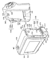
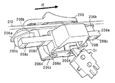
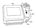
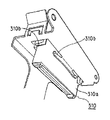
図1は、本実施形態に係る画像表示装置の概略構成を斜視図にて示すものであり、該画像表示装置は、画像表示ユニット100と、画像表示ユニット100に回動自在に取付けられた着脱ユニット200と、該着脱ユニット200に着脱自在であって画像情報の入力部に相当する画像入力ユニット300と、を有する。図1では、着脱ユニット200から画像入力ユニット300を取り外し、その着脱部分を示している。
【0021】
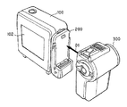
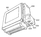
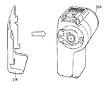
本実施形態では、図2に示すように、着脱ユニット200に種々の画像入力ユニット300を取付けることで、取付けた画像入力ユニット300の特性に応じた画像を画像表示ユニット100に表示可能としている。
【0022】
<画像表示ユニット100>
前記画像表示ユニット100は、画像入力ユニット300から着脱ユニット200を介して入力された画像情報を表示する表示画面102を有しており、使用者が手で持って表示画面102を見られる大きさ、重量に構成されている。
【0023】
また、前記画像表示ユニット100は、画像表示ユニット100に入力された画像情報を書き込み、読み出し可能な記憶媒体、例えば磁気テ―プ、磁気ディスク、半導体メモリ等に記録可能な構成となっており、また、係る記憶媒体に記憶した内容を前記表示画面102に再生表示可能となっている。
【0024】
前記表示画面102は、使用者と対峙する操作側面104の略中央に位置し、例えば、使用者が該画像表示ユニット100を手に持って表示内容を理解できるような大きさとしている。該表示画面102の構成としては、画像情報を表示できる、例えば液晶ディスプレイ、プラズマディスプレイ等、現在知られる表示画面を使用できる。
【0025】
<着脱ユニット200>
前記着脱ユニット200は、図1に示すように、画像表示ユニット100の表示画面102の向かって右側側面106に設けられた縦断面略L字状部材であり、平板状の嵌合部202と、該嵌合部202上に突出するソケット部204とで概略構成されている。
【0026】
前記嵌合部202は、前記画像入力ユニット300と構造的に係合、嵌合する所定厚みを有した板状体であり、前記画像表示ユニット100の右側側面106よりやや小さな大きさに形成している。該嵌合部202には、上面212側からリリースツマミ206、レバー208、及び一対の受け溝210が設けられている。
【0027】
前記リリースツマミ206は、前記嵌合部202の上面部212のユニット100側寄りに、該上面部212に沿って、該嵌合部202の前記画像入力ユニット300との対向面214と同方向に往復動可能なツマミであり、着脱ユニット200から画像入力ユニット300を取外す時に操作される。リリースツマミ206は、操作面側の形状を山形に形成すると共に、表面に細かな凹凸を形成することで、使用者の指の引っ掛りを良くしている。
【0028】
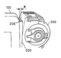
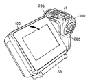
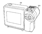
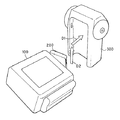
本実施形態では、通常使用時の態様で使用者が誤って前記リリースツマミ206を操作するのを防ぐため、図3のような前記着脱ユニット200と画像入力ユニット300が電気的連結状態では使用者が指で前記リリースツマミ206を操作できないようにし、着脱ユニット200から画像入力ユニット300を取外す場合には、図4に示すように着脱ユニット200に対して画像表示ユニット100とを所定角度回転して前記リリースツマミ206を操作可能に露出させように構成している。
【0029】
すなわち、図3の通常使用時で使用者が指で前記リリースツマミ206を操作できないようにするために、前記リリースツマミ206の取付け位置を図3に示すように、画像表示ユニット100と画像入力ユニット300の上面より凹状に引っ込んだ位置(前記嵌合部202の上面部212)でユニット100側寄に設け、そのサイズを該画像表示ユニット100と画像入力ユニット300の上面よりも低く(凹状)なる高さに形成し、また、画像表示ユニット100と画像入力ユニット300の間隔を規定することとなるリリースツマミ206の幅Wも、上記作用効果を発揮し得る狭い幅に設けている。
【0030】
前記レバー208(図1)は、前記嵌合部202の画像入力ユニット300との対向面214の上方部に設けた孔から突出可能な係止部材であり、画像入力ユニット300側と嵌合して、着脱ユニット200から画像入力ユニット300が後述する第2の方向へのスライド移動防止部材となる。
【0031】
前記リリースツマミ206とレバー208は、連動しており、前記リリースツマミ206を所定方向に移動することで、レバー208が対向面214から引っ込み、着脱ユニット200と画像入力ユニット300の電気的係合(電気的接続関係)を解除できる。また、前記着脱ユニット200に画像入力ユニット300を接続する工程では、レバー208が画像入力ユニット300により押圧されて対向面214から引込み、さらに接続工程完了時にはレバー208が画像入力ユニット300の後述する穴308に突出、挿入し、その間、該レバー208の動きに連動してリリースツマミ206も往復動する。前記リリースツマミ206とレバー208の連動機構を図5、図6に示す。
【0032】
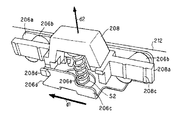
図5に示すようにリリースツマミ206には、上面部212を介して連動して動作するカム206aが連結され、該カム206aにはリリースツマミ206の往復動作方向d1に対して斜め方向に延びる2箇所の誘導溝部206bと、該誘導溝206bと同方向を向く誘導辺206dとセンサ部S1を押圧する押圧部206eとを形成するフランジ206cと、が形成されている。一方、レバー208の基部208aには、前記誘導溝部206bに係合し該溝内を摺動するロッド208bと、複数本の直線状のガイドレール208cと、前記誘導辺206dと係合摺動するアーム208dと、が形成されている。前記レバー208の基部208aは、リリースツマミ206の動作方向d1とは直角方向に延びる図示しないレール溝にガイドレール208cを係合している。また、図6に示すようにレバー208には、レバー208が対向面214から突出する方向d2に付勢するバネS2が設けられている。
【0033】
上記構成により、リリースツマミ206の操作は、カム206aに連動し、誘導溝206b、誘導辺206dからロッド208b、アーム208dに伝達方向を変えながら伝達され、基部208aを介してレバー208の往復動を実現している。また、カム206aの動作に連動する押圧部206e(被検知部)の動きをセンサ部S1が感知することで、リリースツマミ206やレバー208の位置や状態を把握可能としている。
【0034】
本実施形態の画像表示装置では、着脱ユニット200と画像入力ユニット300とが着脱可能となっているために、その着脱に伴う電気的誤動作を防ぐ必要が生じる。
【0035】
例えば、着脱ユニット200と画像入力ユニット300との装着時としては、電源用のバッテリーSB(図4)を下部に設けた画像表示ユニット100で録画データの再生中に画像入力ユニット300の接続し、誤った録画処理を行ってしまった場合等のデータ保護等を必要とするような誤操作が生じる場合が想定され、係るエラー抑制制御が必要となる。
【0036】
また、着脱ユニット200から画像入力ユニット300の分離時としては、画像表示ユニット100の主電源スイッチMS(図1)をON状態中や、画像入力ユニット300により撮像・録画中、或いは画像入力ユニット300の分離処理モード以外等の状態中において、誤って着脱ユニット200から画像入力ユニット300を分離する誤操作がなされる場合が起こり得る。具体的には、着脱ユニット200と画像入力ユニット300の電気的接続を実現している後述するソケット216とプラグ310(図1)には電源線、制御信号線、データ線等が含まれているため、分離可能な安全な状態での処理の終了等を行わずにソケット216とプラグ310を外した場合には、電源線切れに伴う装置自体の機械的エラー(故障)、制御信号線切れによる処理・動作エラー、データ線切れによるデータの記録・保存エラー等の原因となり、係るエラー抑制制御が必要となる。
【0037】
そこで、本画像表示装置では、着脱ユニット200と画像入力ユニット300の接続状態の確立及び解除、より具体的にはソケット216とプラグ310の電気的接続関係の確立及び解除を前記センサS1(図5)を用いて事前に検知し、係るセンサS1からの検知信号を用いて前記誤操作時の安全処理制御を行う安全回路SC(図6)を設けている。以下、詳細に説明する。
【0038】
前記センサS1は、主に、着脱ユニット200と画像入力ユニット300の接続動作時にはレバー208の動作を、その解除動作時にはツマミ206の動作を、それぞれ押圧部206e(被検知部)の動きにて検知している。係る構成により着脱事前検知部を形成している。
【0039】
着脱ユニット200と画像入力ユニット300の装着時には、ソケット216とプラグ310の電気的接続が確立(完了)するまでは、レバー208が画像入力ユニット300により押圧され、対向面214から引込状態となり、その動作と連動して押圧部206eがセンサS1を押圧し、センサS1はOFF信号(未装着/解除信号)を出力する。電気的接続が確立時には、レバー208が画像入力ユニット300の穴308に突出、挿入され、押圧部206eがセンサS1の押圧を解除するためセンサS1はON信号(装着信号)を出力する。
【0040】
一方、着脱ユニット200と画像入力ユニット300の分離時には、ソケット216とプラグ310の電気的接続が解除される前にツマミ206の解除動作と連動する押圧部206eがセンサS1を押圧し、センサS1出力はON信号(装着信号)からOFF信号(未装着/解除信号)に変化する。
【0041】
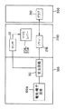
図7は、前記センサS1の信号出力に基づいて着脱ユニット200と画像入力ユニット300の脱着による電気的不具合の発生を回避するための安全回路SCを含めた画像表示ユニット100、着脱ユニット200及び画像入力ユニット300のブロック図を示している。
【0042】
安全回路SCは、画像表示ユニット100内部の電気・電子回路100aとソケット216(図1)との間に位置し、それらと接続され、且つ、センサS1の信号出力を入力可能に接続されている。
【0043】
安全回路SCはセンサS1からのOFF信号を受信することで、着脱ユニット200と画像入力ユニット300の分離及び装着に伴うソケット216とプラグ310の電気的接続の解除と接続を事前に判断できる。
【0044】
そこで、本実施の形態では安全回路SCがOFF信号を受信した場合には、安全回路SCは装置動作を安全状態に移行するように制御する。例えば、処理停止状態や処理終了状態(通常の終了動作と同様に主電源MSがOFF状態となる初期状態)となるように、画像表示ユニット100と画像入力ユニット300とを制御する。
【0045】
安全回路SCの前記制御により、着脱ユニット200と画像入力ユニット300の電気的接続及び解除に伴う画像表示装置内での不慮の動作エラー、故障等の発生を未然に防ぐことができる。
【0046】
また、着脱ユニット200から画像入力ユニット300を取外す目的で設けられたリリースツマミ206と、着脱ユニット200に対する画像入力ユニット300のスライド移動防止を目的に設けられたレバー208と、を着脱事前検知という他の目的にも使用可能とすることで、着脱事前検知用に着脱ユニット200と画像入力ユニット300の着脱を検知する装置を別個に設ける必要がなくなり、装置のコンパクト化や操作部の簡略化が実現できる。また、また、リリースツマミ206とレバー208とを単一のセンサS1で検知可能に形成したので、個別に対応するセンサを設ける場合に較べてさらに装置のコンパクト化が図れる。
【0047】
また、安全状態として処理停止状態と処理終了状態で説明したが、それに限定するものではなく、主電源MS(図1)をON状態で、データ表示、データ送受信、そのデータ送受信に関わる処理等を並行処理可能としてもよい。
【0048】
また、分離前の状態への復帰操作の案内を、再起動時、復帰操作時に案内表示することで、操作性が向上し、よりユーザーフレンドリーな装置とできる。
【0049】
また、本実施の形態では安全回路SCを画像表示ユニット100内に設けたが、その位置を限定するものではなく、適宜、着脱ユニット200或は画像入力ユニット300、又は複数箇所に設けてもよい。
【0050】
また、本実施形態では、押圧部206eがセンサS1を押圧時にOFF信号(未装着/解除信号)を出力し、押圧部206eがセンサS1の押圧しない時にON信号(装着信号)を出力するものとしたが、その逆に押圧部206eがセンサS1を押圧時にON信号(装着信号)、押圧しない時にOFF信号(装着信号)を出力するように押圧部206eとセンサS1の取付位置関係を変更してもよいことは言うまでもない。
【0051】
次に、図1に示す受け溝210を説明する。
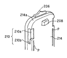
前記受け溝210は、前記対向面214の上方部両側面に設けられた略L字状、鉤状等の2方向(略垂直な2方向)に伸びた溝であり、後述する画像入力ユニット300側の鉤状フック308(図1)と凹凸係合可能としている。より具体的には、図8に拡大して示すように、受け溝210は着脱ユニット200に画像入力ユニット300を装着する方向D1(第1の方向、図2)に延びた装着溝210aと着脱ユニット200に対して入力ユニット300をスライド移動させる方向D2(第2の方向、図9)に延びたスライド溝210b(図8)とを有している。
【0052】
前記対向面214における装着溝210aの開口(図1,図8)は、後述する画像入力ユニット300側の鉤状フック308(図1)の1辺308aが嵌入可能とする大きさであり、前記スライド溝210bは鉤状フック308の1辺308aの厚み分の開口があればよい。従って、装着溝210aとスライド溝210bの開口は大きさが異なっており、受け溝210を対向面214から略L字状に進む方向に見ると装着溝210aの開口(幅)がスライド溝210bの開口(幅)よりも大きく形成されている。
【0053】
前記対向面214(図1)には、加工精度や具材の変形等による誤差を緩和するために、画像入力ユニット300との接続時や係合時等に面接触とせず、線接触を可能とするように、両サイド近傍に第2の方向D2に延びる離間突起Pを設けている。尚、本実施形態では離間突起Pを着脱ユニット200に設けたが、画像入力ユニット300側に設けてもよい。
【0054】
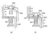
本実施形態では、着脱ユニット200と画像入力ユニット300のスムースな着脱動作を確保するために、着脱ユニット200に画像入力ユニット300を係合した時に離間突起Pと画像入力ユニット300との間にクリアランスL(約0.2mm)を設けている(図12(b)参照)。尚、離間突起Pを設けずにクリアランスLを確保してもよい。
【0055】
前記着脱ユニット200(図1)は、前記画像入力ユニット300を第1の方向D1に装着し易くするために、図8に示すように前記嵌合部202の対向面214は稜線部分を面取り加工し、第1の方向D1に従ってテーパー部分214aを形成している。
【0056】
尚、図示しないが、前記嵌合部202(図1)には画像表示ユニット100との対向面に画像表示ユニット100に対して回動可能とする接続部を有し、該接続部に嵌合部202と画像表示ユニット100の電気的接続部品を設けている。
【0057】
前記ソケット部204は、主に、前記画像入力ユニット300と画像表示ユニット100を電気的に接続する接続部である。該ソケット部204は、ソケット216、一対の取付け溝218、位置合わせ用マーク220、及び下面の三脚取付け部224(図9)を有している。
【0058】
前記ソケット216は、後述するプラグ310と電気的接続を可能とする接続部材(コネクタ)であり、画像表示ユニット100と画像入力ユニット300間の電気信号、電源等の図示しない端子を有し、略対向面214に並行に設けられている。
【0059】
前記取付け溝218は、後述する画像入力ユニット300の緩衝ツメ312が係合する溝であり、ソケット216よりも着脱ユニット200の中心方向に位置している。
【0060】
位置合わせ用マーク220は、使用者が前記画像入力ユニット300を着脱ユニット200に取付ける場合の位置合わせ用に用いるマーク、記号、刻印等である。本実施形態では、△(三角)形のマークを用いており、前記画像入力ユニット300の底面を係る△(三角)形のマークに合わせることで画像入力ユニット300の取付け位置となる。
【0061】
また、ソケット部204は、前記画像入力ユニット300を装着し易く、且つ、装着時のガタツキを無くすために、装着方向(第2の方向D2)に従って断面積が広くなる勾配側面222を有する略台形形状に形成されている。
【0062】
また、前記勾配側面222には、前記対向面214と同様に、離間突起Pを両サイドに所定幅に亘って設けて着脱ユニット200に画像入力ユニット300を係合した時に離間突起Pと画像入力ユニット300との間に多少のクリアランスL(約0.2mm)を設けている(図12(b)参照)。尚、本実施形態では、離間突起Pを着脱ユニット200に設けたが、画像入力ユニット300側に設けてもよい。また、離間突起Pを設けずにクリアランスLを確保してもよい。
【0063】
三脚取付け部224は、図10に示すように着脱ユニット200の底面226に取付け穴として形成し、図11に示すように三脚取付け用の雲台228を取付け可能となっている。着脱ユニット200、特にソケット216に対して画像入力ユニット300を取付る方向の延長方向位置に設けることで、画像入力ユニット300の取付け時に加わる力が三脚方向に逃がすことができ、三脚使用時の画像入力ユニット300の取付けを簡単にできる。また、着脱ユニット200に三脚取付け部224を設けることで、画像表示ユニット100を任意の方向に回転でき、また、三脚に画像表示ユニット100を固定した状態で、画像入力ユニット300を着脱することが実現できる。
【0064】
<画像入力ユニット300>
前記画像入力ユニット300は、画像表示ユニット100に表示する画像や映像情報を入力するものであり、例えば、静止画撮像用カメラ、動画撮像用カメラ、テレビ信号受信アンテナ等を用いることができる。
【0065】
前記静止画撮像用カメラとは、例えば、メカニカルなシャッターにより、CCD(光電気変換素子、撮像素子)の露光を遮断することにより低スピードで多くの画素をCCDから読み込むことが可能なレンズとCCDとを有するカメラ、或はCCDからプログレッシブの映像を読み込むことができるレンズとCCDを有するカメラである。前記動画撮像用カメラとは、例えば、映像方式に沿って、CCDからの画素をインターレースで読み込む事が可能なレンズとCCDを有するカメラである。結果的に、静止画撮像用カメラのCCDの画素数は、動画撮像用カメラのCCDの画素数よりも多くなる。また、テレビ信号受信アンテナとは、公知のテレビ信号の受信用アンテナである。尚、図面上では本実施の形態の画像入力ユニット300としてカメラを用いる場合を示している。
【0066】
以下、画像入力ユニット300の着脱ユニット200との結合部分を中心に説明する。
【0067】
画像入力ユニット300の着脱ユニット200との結合側面302(図1)には、該着脱ユニット200を略嵌合状態に収容可能な凹部(窪み)304を設けている。
【0068】
凹部304の奥行き幅DPは、図3に示すように該着脱ユニット200を略嵌合状態で、前記着脱ユニット200のレバー208、受け溝210、ソケット216、及び取付け緩衝溝218が露出せず、リリースツマミ206のみが露出する幅に形成している。
【0069】
前記凹部304には、着脱ユニット200を接続した時に、前記着脱ユニット200のレバー208、一対の受け溝210、ソケット216、及び取付け緩衝溝218と其々係合、結合等する穴306、一対の鉤状フック308、プラグ310、及び緩衝ツメ312を対応する位置に形成している。
【0070】
前記凹部304は、着脱ユニット200を覆うように構成することで、画像入力ユニット300の回動負荷が凹部304に掛り、直接、プラグ310とソケット216のみに加わることを防止している。前記作用効果は、取付け時に凹部304が対向する着脱ユニット200の対向面214と勾配側面222の全面又はその一部を覆いつつ、該対向面214や勾配側面222と隣り合う2以上の方向を向く側面の全面又は一部を覆うように形成することで奏することができる。
【0071】
前記穴306は、レバー208を係合可能な穴であり、着脱ユニット200に接続状態の画像入力ユニット300の装着方向(第2の方向D2)の可動を規制する。
【0072】
前記鉤状フック308は、前記受け溝210と凹凸係合する略鉤状、L字状の突片であり、凹部(窪み)304の壁面より起立し、互いに略直行するフック片308a、308bから構成されている。
【0073】
前記プラグ310は、前記ソケット216と嵌合する電気的接続部材(コネクタ)であり、図示しない配線端子を有している。該プラグ310は、前記ソケット216との接続時の位置ずれから生じる不安定な接続動作を防ぐために、前記ソケット216との接続方向(第2の方向D2、図9)と略直角方向の可動(フローティイング)可能な構成としている。具体的には、プラグ310は、図12、13に示すように電気信号、電源等の端子(図示しない)を有する略U字状のホルダー310aと該ホルダー310aを4方より挟み込む弾性部材310bとを有している。本実施形態では、弾性部材310bとして板バネを用いたが、その他の種類のバネやゴム等でもよい。尚、プラグ310は、フローティイングと共に傾倒可能ともできる。
【0074】
前記プラグ端子310のフローティング量は、適宜装着実験等により最適な量を決定できるが、本実施形態では図12(b)に示すように画像入力ユニット300と着脱ユニット200のクリアランス量Lの1.5倍以上に設定している。より具体的には、前記クリアランスL(0.2mm)に対してフローティングを0.5mm(2.5倍)としている。
【0075】
前記緩衝ツメ312(図1)は、プラグ310より外側(凹部304の開口寄り)に位置する凸片であり、使用者が誤ってプラグ310を直接、例えば、鉤状フック308を受け溝210に係合することなしに前記ソケット216に接続する時に、その接続を防ぐと共に、プラグとソケットの干渉による破損を防ぐものである。
【0076】
前記緩衝ツメ312は、直接、プラグ310をソケット216に接続しようとした時には、プラグ310が前記ソケット216に接触する前に緩衝ツメ312がソケット部204の勾配側面222等の外周面に接触、干渉する大きさに形成されている。
【0077】
また、前記緩衝ツメ312は、画像入力ユニット300を着脱ユニット200に正規の接続方向(鉤状フック308を受け溝210に係合しながらの接続方向、第2の方向D2、図9)にスライド嵌合する時に、着脱ユニット200の取付け溝218と係合する。
【0078】
尚、緩衝ツメ312の大きさを、前記プラグ310とソケット216とが接続する前に取付け溝218と所定抵抗をもって嵌合する大きさに形成すれば、前記プラグ310とソケット216の接続直前の緩衝材となり、誤った力が端子に伝達されるのを未然に防ぐことができる。
【0079】
凹部304の壁面は、前記したように前記プラグ310がソケット216に嵌合した状態で前記着脱ユニット200との間にクリアランス量Lを設けるように形成されている。
【0080】
また、画像入力ユニット300と着脱ユニット200のガタツキ防止のために緩衝材としてクッション部材C(図11,図12)をユニット200、300間に設けている。
【0081】
前記着脱ユニット200から外した前記画像入力ユニット300は、プラグ310等が露出するため、図14に示すように前記凹部304を閉じるように嵌め込み可能なカバー314を形成した。従って、未使用時の画像入力ユニット300のプラグ310等への埃、塵、水分等が付着するのを防ぐことができる。尚、カバー312は、画像入力ユニット300の種類に関らず共通の形状としている。
【0082】
次に、前記着脱ユニット200への前記画像入力ユニット300の着脱動作を、図面を参照しながら説明する。
【0083】
<取付け時>
先ず、図2に示すように、前記着脱ユニット200の対向面214と前記画像入力ユニット300の凹部304を対向させた状態で近づけ、着脱ユニット200の位置合わせ用マーク220と画像入力ユニット300の底辺を合わせる。係る状態で、必然的に装着溝210aの開口にフック片308aが挿入可
能となると共に、レバー208が凹部304壁面に接触する。
【0084】
更に着脱ユニット200と画像入力ユニット300を接近方向(第1の方向D1)に進めることで、装着溝210aにフック片308aが挿入し、且つ、レバー208が凹部304壁面に押圧されてセンサ部S1の検出信号が変化する。係る検出信号により、画像入力ユニット300の取付けを感知でき、取付け時の安全装置(安全回路SC)が画像表示ユニット100内部の電気・電子回路100aを安全状態(初期状態、処理保存状態、或は並列処理状態)に移行し、ご操作による事故の未然防止ができる。
【0085】
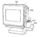
次に、図9に示すように画像入力ユニット300を第1の方向D1と略直角な第2の方向D2、すなわちソケット端子216の配置方向にスライドすることで、フック片308aが装着溝210bに係合し、レバー208が穴306に突出係合する。係る状態で、センサS1の検出信号が変化し、画像入力ユニット300の取付け終了を感知し、取付け時の安全装置(安全回路SC)が画像表示ユニット100内部の電気・電子回路100aを初期状態、或は、接続前の処理の継続処理可能状態とする。また、これと並行して、緩衝ツメ312が先ず緩衝溝218に嵌合し、続いてプラグ310がソケット216に嵌合する。
【0086】
レバー208と穴306の係合で、両ユニット200、300の第2の方向D2への動きを規制し、フック片308aと装着溝210bの係合で、両ユニット200、300の第1の方向D1と奥行き方向の動きを規制し、図15に示すように製品の使用状態となる。
【0087】
プラグ310をソケット216に1方向に接近,接続する場合に、使用者が接続動作に集中せずに行うと間違って無理な力を加えたり、不慮の衝突等を起こし、思いがけなくプラグ310とソケット216を衝突させて破損させてしまう場合がある。しかしながら、本実施形態の場合には、プラグ310をソケット216に接続するのに異なる2方向以上(第1,第2の方向D1,D2、又は複数方向)に画像入力ユニット300を動かす必要性があるため、使用者は1方向目の動作で間違った無理な力を加えてしまってもプラグ310とソケット216を衝突させることはなく、更に、単純に1方向での接続ではないので使用者の意識を接続動作に集中する方向に向けることができるので、プラグ310とソケット216を衝突させて破損させてしまうような事故を未然に防ぐことができる。
【0088】
前記緩衝ツメ312を前記プラグ310よりも外側位置(開口側)に設け、該第1、第2方向への接続動作なしに、直接、プラグ310を前記ソケット216に接続しようとしても、プラグ310が前記ソケット216に接触する前に緩衝ツメ312がソケット部204の外周面に接触するので、誤った取付け動作によるプラグ310とソケット216の破損を未然に防止できる。
【0089】
前記プラグ310がソケット216との接続方向(第2の方向D2、図9)と略直角方向にスライド移動(フローティング)可能な構成とすることで、着脱ユニット200と画像入力ユニット300間にクリアランスLからプラグ310とソケット216とが接続時に多少ズレる場合であっても、プラグ310が接続方向にスライド、傾倒し、安定した接続を維持できる。
【0090】
また、ソケット部204は装着方向(第2の方向D2)に従って断面積が広くなる勾配側面222を有する略台形形状に形成しているので、装着中のクリアランスよりも装着完了時のクリアランスを小さくでき、使用時のガタを減らす効果がある。
【0091】
また、使用時に、画像入力ユニット300と着脱ユニット200間でガタが手に感じると撮影において画面ブレを起こし得るため、ユニット200、300間にクッション部材312を設けることで、ガタツキ防止を可能とするとともに、両ユニットの着脱動作の際の衝撃を和らげ、部品の破損を防止できる。
【0092】
<取外し時>
画像入力ユニット300の着脱ユニット200からの取外しは、前記リリースツマミ206を操作し、着脱ユニット200のレバー208の画像入力ユニット300の穴306への係合を外すことで行われる。
【0093】
一方、図15に示すような着脱ユニット200に対して画像表示ユニット100が所定傾斜範囲内(基準状態)では使用者が指で前記リリースツマミ206を操作できない構成であって、前記リリースツマミ206を操作するには図4に示すように着脱ユニット200に対して画像表示ユニット100を所定角度回転状態とすることで前記リリースツマミ206が露出し、操作可能となる。係る構成により、使用頻度の高い基準状態での使用中に誤ってリリースツマミ206を操作する誤動作を防ぐことができる。
【0094】
使用者が前記リリースツマミ206を操作した時点で、該ツマミ206の動きをセンサ部S1が検知し、プラグ310と前記ソケット216の引き抜き前に、プラグ310と前記ソケット216の引き抜きに伴う事故を未然に防ぐために電気的安全回路SCが画像表示ユニット100内部の電気・電子回路100aを安全状態(初期状態、処理保存状態、或は並列処理状態)に移行する。
を作動する。
【0095】
前記リリースツマミ206を操作し、レバー208と穴306の係合を解除した後は、前記取付け順序と逆向きに、図16に示すように着脱ユニット200に対して画像入力ユニット300を第2の方向D2へスライド移動し、続いて第1の方向D1に移動、分離することとなる。
【0096】
なお、前記の実施形態では本発明の好適例を説明したが、本発明はこれに限定されないことはもちろんである。
例えば、本実施形態では、第1、第2の方向として直線的な方向を説明したが、例えば第2の方向等を回転方向等にすることもできる。
【0097】
また、本実施形態では、前記鉤状フック308を用いているが、それに替えて単なる棒状部材をフックに用いた場合には、受け溝210を使用できる他に3方向以上の受け溝にも対応できる。従って、係る棒状フックを用いた場合、着脱ユニット200への画像入力ユニット300の装着方向を3以上もできる。
【0098】
また、本実施形態では、着脱ユニット200と画像入力ユニット300の2方向以上の係合動作を実現するために、着脱ユニット200側に受け溝210を設け、画像入力ユニット300側に前記鉤状フック308等を設けたが、着脱ユニット200側に前記鉤状フック308等を設け、画像入力ユニット300側に受け溝210を設けても上記同様の作用効果を得ることができる。
【0099】
また、プラグ310をフローティング構造としたが、ソケット216がソケット部204に対して移動可能にフローティング構造としてもよく、また双方のコネクタをフローティング構造としてもよい。
【0100】
また、上記実施形態では、着脱ユニット200と画像入力ユニット300の情報伝達を有線で電気的接続部材(コネクタ)を介して行う場合を説明したが、着脱ユニット200と画像入力ユニット300との情報伝達方法はそれに限定するものではなく、無線(電波,光等)の送受信機、例えば近距離通信に適した赤外線送受信を前記ソケット216とプラグ310に替わって用いることで、ソケット216とプラグ310のように機械的係合を必要とせず、着脱ユニット200と画像入力ユニット300の着脱部分の構成が簡単化できる。尚、無線の送受信機を用いる場合には、着脱ユニット200に対して画像入力ユニット300が少なくとも異なる2方向以上の係合移動動作後に始めての情報伝達可能な位置にその送信機と受信機を配置する必要がある。
【0101】
【発明の効果】
以上説明した通り、本発明によれば接続部に画像入力部を取付ける際に、2方向以上に取付け動作を意図的に行う必要があるので、使用者の意識を取付け動作に集中させることができるため不注意による衝突等を防ぎ、電気コネクタ等の破損を防ぐことができる。また、接続部と画像入力部の接続方向を変えるという簡単な操作であるので、子供や年輩の方等でも簡単に着脱できる。また、着脱検知部と安全回路部を設けることで、接続部と画像入力部の不適切な着脱に伴う装置の故障、処理エラー、データの破損等を未然に防ぐことができ、安全性、取扱性の高い装置とできる。
【図面の簡単な説明】
【図1】本発明の実施形態に係る画像表示装置の分解斜視図である。
【図2】本発明の実施形態に係る画像入力ユニット300を着脱ユニット200に第1の方向D1に装着する説明図である。
【図3】本発明の実施形態に係るリリースツマミ206の説明図である。
【図4】本発明の実施形態に係る着脱ユニット200から画像入力ユニット300を取外すための操作説明図である。
【図5】本発明の実施形態に係るリリースツマミ206とレバー208の連動機構の説明図である。
【図6】本発明の実施形態に係るリリースツマミ206とレバー208の連動機構の説明図である。
【図7】本発明の実施形態に係る安全回路SCを含めた画像表示ユニット100、着脱ユニット200及び画像入力ユニット300のブロック図である。
【図8】本発明の実施形態に係る着脱ユニット200上部の斜視図である。
【図9】本発明の実施形態に係る画像入力ユニット300を着脱ユニット200に第2の方向D2に装着する説明図である。
【図10】本発明の実施形態に係る着脱ユニット200下部の斜視図である。
【図11】本発明の実施形態に係る着脱ユニット200に雲台228を取付けた状態の斜視図である。
【図12】本発明の実施形態に係るソケット216とプラグ310の構成説明図である。
【図13】本発明の実施形態に係るプラグ310の斜視図である。
【図14】本発明の実施形態に係る画像入力ユニット300へのカバー312装着説明図である。
【図15】本発明の実施形態に係る画像表示装置の斜視図である。
【図16】本発明の実施形態に係る画像入力ユニット300を着脱ユニット200から取外す作用的説明図である。
【符号の説明】
100 画像表示ユニット
102 表示画面
200 着脱ユニット
206 リリースツマミ
SC 安全回路
210 受け溝
214 対向面
D1 第1の方向
D2 第2の方向
P 離間突起
L クリアランス
216 ソケット
224 三脚取付け部
300 画像入力ユニット
304 凹部
308 鉤状フック
310 プラグ
310a ホルダー
310b 弾性部材[0001]
TECHNICAL FIELD OF THE INVENTION
The present invention relates to an image display device that displays image information captured and received by an image input unit such as a camera or a receiving device on a monitor unit, and in particular, an image display device that allows the image input unit to be attached and detached and the image display device. Regarding the input unit.
[0002]
[Prior art]
2. Description of the Related Art Conventionally, as an imaging device having a camera unit and a monitor unit that is operated by hand, a still image imaging device (for example, a so-called digital camera) that displays a high-resolution still image on a monitor unit and a moving image that is displayed on a monitor unit And a moving image pickup device for displaying the same.
[0003]
Such a moving image and a still image imaging device are separate imaging devices because of a large difference in resolution.
[0004]
On the other hand, since the monitor unit of both imaging devices can be used in common, the imaging device is configured to be separable into a monitor unit and a camera unit, and a common monitor unit or a camera unit for moving images or By selectively attaching the camera unit, the monitor unit can be effectively used.
[0005]
[Problems to be solved by the invention]
However, by making the monitor unit and the camera unit, which are conventionally integrally configured, detachable, the connection strength that can be carried around is ensured, and the detachability is important. Regarding the operability of attaching / detaching, especially since the imaging device is used from children to seniors, in addition to being easy to attach / detach, it is possible to prevent the connection portion from being damaged even if the user performs an improperly improper mounting method. There is a demand for an image display device including a connection portion of an image input portion for preventing accidental detachment of a camera portion during use.
[0006]
The present invention has been made in order to solve the above-mentioned problems. Even when used by users of a wide range of age groups, such as children and seniors, the image input unit may be erroneously attached or connected. It is an object of the present invention to provide an image display device including a connection portion of an image input unit that can prevent damage beforehand, and an image input unit thereof.
[0007]
[Means for Solving the Problems]
The present invention has the following configuration to achieve the above object.
In the present invention, a connection unit is provided that is connected to an image display unit that displays an image based on image information, and that detachably connects an image input unit that inputs image information displayed on the display unit. A connection unit and an image input unit are formed that allow the image input unit to transmit image information from the image input unit to the connection unit by performing an engagement movement operation in at least two different directions.
[0008]
According to the above configuration, if the image input unit can be connected to the connection unit in one direction, an excessive force may be erroneously applied. However, the connection unit and the image input unit are engaged in at least two directions. By performing the combined movement operation, even if the engagement movement operation in the first direction is erroneously performed, it is necessary to concentrate attention on the engagement movement operation in the different second direction. Can be prevented beforehand. In addition, since a simple operation only for changing the engagement movement operation is added to the user, safe use by users of a wide age range can be ensured.
[0009]
By forming the engagement portion between the connection portion and the image input portion with, for example, a substantially hook-shaped groove or projection directed substantially in the same direction as the two directions, the engagement movement operation in two or more directions can be easily realized.
[0010]
Further, when an electric connector is used as a means for transmitting image information between the connection unit and the image input unit, for example, damage to the electric connector due to incorrect connection of the image input unit can be prevented.
[0011]
At least one of the connection section electrical connector and the image input section electrical connector can be moved, for example, in a direction substantially perpendicular to the connection direction of the two electrical connectors, thereby eliminating damage and poor connection at the time of mutual connection. it can. That is, between the connection unit and the image input unit, in order to facilitate the connection, at least at the time of connection is designed to provide a predetermined gap between each other, due to such a gap, both electrical connectors are buffered, Although there is a possibility of causing breakage or poor connection, the electrical connector can be moved in a direction substantially perpendicular to the connection direction, and it moves in the connection direction when both connectors are connected, so interference such as damage may occur. Can be suppressed and a secure connection can be secured.
[0012]
The connection unit is provided with a release operation unit for removing the image input unit at a position sandwiched between the image input unit and the image display unit, and when the connection unit is in the first positional relationship with the image display unit. When the release operation unit cannot be operated by the user's finger and the image display unit is rotated with respect to the connection unit to change from the first positional relationship to the second positional relationship, the release operation is performed by the user's finger. By enabling the operation of the unit, it is possible to prevent a malfunction in which the release operation unit is accidentally operated during use and the image input unit is unexpectedly removed. Further, by detecting the operation of the release operation unit and controlling the electrical safety circuit, it is possible to prevent the electric components in the apparatus, the image data, and the like from being damaged.
[0013]
Further, when the image input unit is connected to the connection unit, the image input unit covers at least a part of each surface of the connection unit in the three directions, so that the connection strength between the image input unit and the connection unit against the rotation operation can be secured, The load on the electrical connector due to the operation can be reduced.
[0014]
Further, as a means for transmitting image information between the connection unit and the image input unit, for example, by using a wireless transmission / reception device, the number of connection points between the connection unit and the image input unit can be reduced, so that the attachment / detachment structure is simplified. Can be.
[0015]
In addition, by providing, for example, a tripod attachment portion in the connection portion, free rotation of the image display portion can be ensured even when the tripod is attached. In addition, since the tripod mounting portion can be provided in the direction of extension of the force applied when the image input portion is connected to the connection portion, the attachment / detachment operation of the image input portion when the tripod is used can be simplified.
[0016]
Also, an attachment / detachment detection unit that detects in advance the occurrence of a state transition between the electrical connection state of the image input unit and the connection unit and the electrical separation state, and a state transition based on a detection signal from the attachment / detachment detection unit. By providing a safety circuit unit that executes error suppression control before the state transition, which suppresses an error that occurs due to the above, even if an erroneous operation such as erroneously attaching and detaching the image input unit and the connection unit is performed by having the safety circuit unit , Device failure, data corruption, etc. can be prevented beforehand.
[0017]
A release member for positioning the attachment / detachment detection unit at a first position in an electrically connected state, and a lever member located at a second position in the electrically separated state; and a release operation for moving the lever member to the first and second positions. And a sensor that detects the first and second positions of the lever member and outputs the detection signal, so that the image input unit and the electrical connector of the connection unit can be connected and disconnected between the connected and disconnected states. Before the transition, the lever member moves, so that by detecting the position of the lever member, advance detection of the transition between the connection and disconnection states of the electrical connector can be easily performed.
[0018]
Further, the lever member is a member for restricting the separation of the electrical connection state at the first position, and the release operation portion can release the restriction of the lever member. Is operated, the transition of the electrical connector to the separated state can be reliably detected.
[0019]
Further, by using the release operation unit as an operation unit operated to remove the image input unit from the connection unit, operability can be improved due to downsizing of the apparatus and simplification of operation parts.
[0020]
BEST MODE FOR CARRYING OUT THE INVENTION
Hereinafter, embodiments of the present invention will be described in detail with reference to the drawings.
FIG. 1 is a perspective view showing a schematic configuration of an image display device according to the present embodiment. The image display device includes an
[0021]
In the present embodiment, as shown in FIG. 2, by attaching various
[0022]
<
The
[0023]
The
[0024]
The
[0025]
<
As shown in FIG. 1, the
[0026]
The
[0027]
The
[0028]
In the present embodiment, in order to prevent the user from operating the
[0029]
That is, in order to prevent the user from operating the
[0030]
The lever 208 (FIG. 1) is a locking member that can protrude from a hole provided above the
[0031]
The
[0032]
As shown in FIG. 5, a
[0033]
With the above-described configuration, the operation of the
[0034]
In the image display device of the present embodiment, since the
[0035]
For example, when the
[0036]
When the
[0037]
Therefore, in the present image display device, establishment and release of the connection state between the
[0038]
The sensor S1 mainly detects the operation of the
[0039]
When the
[0040]
On the other hand, when the
[0041]
FIG. 7 shows an
[0042]
The safety circuit SC is located between the electric / electronic circuit 100a inside the
[0043]
By receiving the OFF signal from the sensor S1, the safety circuit SC can determine beforehand the disconnection and connection of the electrical connection between the
[0044]
Therefore, in the present embodiment, when the safety circuit SC receives the OFF signal, the safety circuit SC controls the operation of the device to shift to the safe state. For example, the
[0045]
By the control of the safety circuit SC, it is possible to prevent the occurrence of an unexpected operation error, failure, or the like in the image display device due to the electrical connection and disconnection of the
[0046]
In addition, a
[0047]
The safety state has been described in terms of the processing stop state and the processing end state. However, the present invention is not limited to this. The data display, data transmission / reception, and processing related to the data transmission / reception are performed with the main power supply MS (FIG. 1) turned on. Parallel processing may be possible.
[0048]
In addition, the guidance of the return operation to the state before the separation is displayed at the time of the restart and the return operation, so that the operability is improved and the device can be made more user-friendly.
[0049]
Further, in the present embodiment, the safety circuit SC is provided in the
[0050]
In the present embodiment, the
[0051]
Next, the receiving
The receiving
[0052]
The opening (FIGS. 1 and 8) of the mounting
[0053]
The opposite surface 214 (FIG. 1) can be in line contact with the
[0054]
In the present embodiment, in order to ensure a smooth attachment / detachment operation between the
[0055]
In the detachable unit 200 (FIG. 1), as shown in FIG. 8, the facing
[0056]
Although not shown, the fitting portion 202 (FIG. 1) has a connecting portion on the surface facing the
[0057]
The
[0058]
The
[0059]
The mounting
[0060]
The
[0061]
The
[0062]
Further, similarly to the facing
[0063]
The
[0064]
<
The
[0065]
The camera for capturing a still image is, for example, a lens and a CCD that can read many pixels from the CCD at a low speed by blocking exposure of the CCD (photoelectric conversion element, imaging element) by a mechanical shutter. Or a camera having a lens and a CCD capable of reading progressive video from a CCD. The moving image capturing camera is, for example, a camera having a lens and a CCD that can read pixels from the CCD in an interlaced manner according to a video system. As a result, the number of pixels of the CCD of the still image capturing camera becomes larger than the number of pixels of the CCD of the moving image capturing camera. The television signal receiving antenna is a known television signal receiving antenna. It should be noted that the drawing shows a case where a camera is used as the
[0066]
Hereinafter, a description will be given focusing on a portion where the
[0067]
On the side surface 302 (FIG. 1) of the
[0068]
The depth DP of the
[0069]
When the
[0070]
The
[0071]
The
[0072]
The hook-shaped
[0073]
The
[0074]
The optimum amount of floating of the
[0075]
The cushioning claw 312 (FIG. 1) is a convex piece located outside the plug 310 (closer to the opening of the concave portion 304), and the user mistakenly inserts the
[0076]
When the
[0077]
The
[0078]
If the size of the
[0079]
The wall surface of the
[0080]
Also, a cushion member C (FIGS. 11 and 12) is provided between the
[0081]
The
[0082]
Next, the operation of attaching and detaching the
[0083]
<When mounting>
First, as shown in FIG. 2, the opposing
At the same time, the
[0084]
Further, when the
[0085]
Next, as shown in FIG. 9, the
[0086]
The engagement of the
[0087]
When the
[0088]
The
[0089]
The
[0090]
In addition, since the
[0091]
In addition, when the user feels backlash between the
[0092]
<When removing>
The detachment of the
[0093]
On the other hand, when the
[0094]
At the time when the user operates the
Operate.
[0095]
After the
[0096]
Although the preferred embodiment of the present invention has been described in the above embodiment, the present invention is of course not limited to this.
For example, in the present embodiment, linear directions have been described as the first and second directions. However, for example, the second direction or the like may be a rotation direction or the like.
[0097]
Further, in the present embodiment, the hook-shaped
[0098]
In the present embodiment, a receiving
[0099]
Further, although the
[0100]
Further, in the above-described embodiment, the case where the information transmission between the
[0101]
【The invention's effect】
As described above, according to the present invention, when attaching the image input unit to the connection unit, it is necessary to intentionally perform the attaching operation in two or more directions, so that the user's consciousness can be concentrated on the attaching operation. Therefore, it is possible to prevent inadvertent collision and the like, and prevent damage to the electrical connector and the like. Further, since the operation is a simple operation of changing the connection direction between the connection unit and the image input unit, even a child or an elderly person can easily attach / detach. In addition, by providing a detachment detection unit and a safety circuit unit, it is possible to prevent device failures, processing errors, data corruption, etc. due to improper attachment / detachment of the connection unit and image input unit. It can be a device with high performance.
[Brief description of the drawings]
FIG. 1 is an exploded perspective view of an image display device according to an embodiment of the present invention.
FIG. 2 is an explanatory diagram of attaching an
FIG. 3 is an explanatory diagram of a
FIG. 4 is an operation explanatory diagram for removing the
FIG. 5 is an explanatory diagram of an interlocking mechanism of a
FIG. 6 is an explanatory diagram of an interlocking mechanism of a
FIG. 7 is a block diagram of an
FIG. 8 is a perspective view of the upper part of the
FIG. 9 is an explanatory diagram of attaching the
FIG. 10 is a perspective view of a lower portion of the
FIG. 11 is a perspective view showing a state in which a
FIG. 12 is a configuration explanatory view of a
FIG. 13 is a perspective view of a
FIG. 14 is an explanatory diagram of attaching the
FIG. 15 is a perspective view of the image display device according to the embodiment of the present invention.
FIG. 16 is an operational explanatory view of detaching the
[Explanation of symbols]
100 image display unit
102 Display screen
200 detachable unit
206 Release Knob
SC safety circuit
210 receiving groove
214 facing surface
D1 First direction
D2 Second direction
P Separated protrusion
L clearance
216 socket
224 Tripod mounting part
300 image input unit
304 recess
308 hook hook
310 plug
310a holder
310b Elastic member
Claims (21)
前記画像表示部と接続し、且つ、前記画像表示部で表示する画像情報を入力する画像入力部を着脱可能に接続する接続部と、を有し、
前記接続部は、前記画像入力部と少なくとも異なる2方向以上の係合移動動作により前記画像情報を該画像入力部から入力可能とする係合部を有することを特徴とする画像入力部の接続部を備える画像表示装置。An image display unit that displays an image based on the image information;
A connection unit connected to the image display unit and detachably connected to an image input unit for inputting image information to be displayed on the image display unit,
The connection unit of the image input unit, wherein the connection unit includes an engagement unit that can input the image information from the image input unit by an engagement movement operation in at least two directions different from the image input unit. An image display device comprising:
前記着脱検知部からの検知信号に基づいて、前記状態移行に伴い発生するエラーを抑制するエラー抑制制御を、前記状態移行前に実行する安全回路部と、
を有することを特徴とする請求項3又は4に記載の画像入力部の接続部を備える画像表示装置。A detachment detection unit that detects in advance the occurrence of a state transition between the electrical connection state and the electrically separated state of the image input unit side electrical connector and the connection unit side electrical connector,
Based on a detection signal from the attachment / detachment detection unit, an error suppression control that suppresses an error that occurs with the state transition, a safety circuit unit that executes before the state transition,
An image display device comprising the connection unit of the image input unit according to claim 3.
前記電気的接続状態で第1の位置に位置し、前記電気的分離状態で第2の位置に位置するレバー部材と、
前記レバー部材を前記第1、第2の位置に移動させるリリース操作部と、
前記レバー部材の前記第1、第2の位置を検知し、該検知信号を出力するセンサと、
を有することを特徴とする請求項5に記載の画像入力部の接続部を備える画像表示装置。The attachment / detachment detection unit,
A lever member located at a first position in the electrical connection state and a second position in the electrical separation state;
A release operation unit for moving the lever member to the first and second positions;
A sensor that detects the first and second positions of the lever member and outputs the detection signal;
An image display device comprising: a connection portion of an image input portion according to claim 5.
前記リリース操作部は、前記レバー部材の前記規制を解除可能であることを特徴とする請求項6に記載の画像入力部の接続部を備える画像表示装置。The lever member is a member that regulates separation of the electrical connection state at the first position,
The image display device according to claim 6, wherein the release operation unit is capable of releasing the restriction of the lever member.
前記接続部に対して少なくとも異なる2方向以上の係合移動動作により前記接続状態とする係合部と、
前記少なくとも異なる2方向以上の係合移動動作により接続部の情報入力部に前記画像情報を出力可能となる情報出力部と、を有することを特徴とする画像入力部。An image input unit that is detachable with a connection unit of an image display unit that displays an image based on image information and transmits image information input according to a connection state with the connection unit to the image display unit,
An engagement portion that sets the connection state by an engagement movement operation in at least two different directions with respect to the connection portion;
An information output unit that can output the image information to an information input unit of the connection unit by the engagement movement operation in at least two different directions.
前記画像表示部で表示する画像情報を入力する画像入力部と、
前記画像表示部と接続し、且つ、前記画像入力部を着脱可能に接続する接続部と、を有し、
前記接続部は、前記画像入力部と係合する接続部側係合部を有し、
前記画像入力部は、前記接続部側係合部と係合する入力部側係合部を有し、
前記接続部側係合部に対して前記入力部側係合部が少なくとも異なる2方向以上の係合移動動作により前記接続部に前記画像入力部が前記画像情報を出力可能となることを特徴とする画像入力部の接続部を備える画像表示装置。An image display unit that displays an image based on the image information;
An image input unit for inputting image information to be displayed on the image display unit,
A connection unit connected to the image display unit, and detachably connected to the image input unit,
The connecting portion has a connecting portion side engaging portion that engages with the image input portion,
The image input unit has an input unit-side engagement unit that engages with the connection unit-side engagement unit,
The image input unit can output the image information to the connection unit by an engagement movement operation of the input unit side engagement unit in at least two different directions with respect to the connection unit side engagement unit. An image display device comprising a connection unit for an image input unit.
前記画像表示部に対して前記接続部が第1の位置関係にある場合には、使用者の指により前記リリース操作部を操作できず、
前記画像表示部を前記接続部に対して回転させ、前記第1の位置関係から第2の位置関係とした場合は、使用者の指により前記リリース操作部を操作できることを特徴とする請求項11に記載の画像入力部の接続部を備える画像表示装置。The connection unit has a release operation unit for removing the image input unit at a position sandwiched between the image input unit and the image display unit,
When the connection unit is in the first positional relationship with the image display unit, the release operation unit cannot be operated by a user's finger,
12. The release operation unit can be operated by a user's finger when the image display unit is rotated with respect to the connection unit to change the first positional relationship to the second positional relationship. An image display device comprising the connection unit of the image input unit according to Claim 1.
前記入力部側係合部は、前記2方向と略同一方向を向く突起であることを特徴とする請求項11に記載の画像入力部の接続部を備える画像表示装置。The connecting portion side engaging portion is a substantially hook-shaped groove that faces in substantially the same direction as the two directions,
The image display device according to claim 11, wherein the input unit-side engagement unit is a protrusion that faces in substantially the same direction as the two directions.
前記入力部側係合部は、前記2方向と略同一方向を向く略鉤状の溝であることを特徴とする請求項11に記載の画像入力部の接続部を備える画像表示装置。The connecting portion-side engaging portion is a protrusion that faces substantially the same direction as the two directions,
The image display device according to claim 11, wherein the input unit-side engaging portion is a substantially hook-shaped groove that faces in substantially the same direction as the two directions.
前記着脱検知部からの検知信号に基づいて、前記状態移行に伴い発生するエラーを抑制するエラー抑制制御を、前記状態移行前に実行する安全回路部と、
を有することを特徴とする請求項15又は16に記載の画像入力部の接続部を備える画像表示装置。A detachment detection unit that detects in advance the occurrence of a state transition between the electrical connection state and the electrically separated state of the image input unit side electrical connector and the connection unit side electrical connector,
Based on a detection signal from the attachment / detachment detection unit, an error suppression control that suppresses an error that occurs with the state transition, a safety circuit unit that executes before the state transition,
An image display device comprising: a connection portion of an image input portion according to claim 15.
前記電気的接続状態で第1の位置に位置し、前記電気的分離状態で第2の位置に位置するレバー部材と、
前記レバー部材を前記第1、第2の位置に移動させるリリース操作部と、
前記レバー部材の前記第1、第2の位置を検知し、該検知信号を出力するセンサと、
を有することを特徴とする請求項18に記載の画像入力部の接続部を備える画像表示装置。The attachment / detachment detection unit,
A lever member located at a first position in the electrical connection state and a second position in the electrical separation state;
A release operation unit for moving the lever member to the first and second positions;
A sensor that detects the first and second positions of the lever member and outputs the detection signal;
An image display device comprising: a connection unit of an image input unit according to claim 18.
前記リリース操作部は、前記レバー部材の前記規制を解除可能であることを特徴とする請求項19に記載の画像入力部の接続部を備える画像表示装置。The lever member is a member that regulates separation of the electrical connection state at the first position,
20. The image display device according to claim 19, wherein the release operation unit is capable of releasing the restriction of the lever member.
Priority Applications (1)
| Application Number | Priority Date | Filing Date | Title |
|---|---|---|---|
| JP2003169717A JP2004088738A (en) | 2002-07-04 | 2003-06-13 | Image display device having connection unit for image input unit and image input unit thereof |
Applications Claiming Priority (2)
| Application Number | Priority Date | Filing Date | Title |
|---|---|---|---|
| JP2002196266 | 2002-07-04 | ||
| JP2003169717A JP2004088738A (en) | 2002-07-04 | 2003-06-13 | Image display device having connection unit for image input unit and image input unit thereof |
Publications (1)
| Publication Number | Publication Date |
|---|---|
| JP2004088738A true JP2004088738A (en) | 2004-03-18 |
Family
ID=32072000
Family Applications (1)
| Application Number | Title | Priority Date | Filing Date |
|---|---|---|---|
| JP2003169717A Pending JP2004088738A (en) | 2002-07-04 | 2003-06-13 | Image display device having connection unit for image input unit and image input unit thereof |
Country Status (1)
| Country | Link |
|---|---|
| JP (1) | JP2004088738A (en) |
Cited By (3)
| Publication number | Priority date | Publication date | Assignee | Title |
|---|---|---|---|---|
| JP2008082708A (en) * | 2006-09-25 | 2008-04-10 | Nittan Co Ltd | Smoke detector |
| JP2009152681A (en) * | 2007-12-18 | 2009-07-09 | Sony Corp | Adapter mounting device, imaging device and adapter |
| WO2019009907A1 (en) * | 2017-07-06 | 2019-01-10 | Hewlett-Packard Development Company, L.P. | Mounting assemblies for peripheral modules |
-
2003
- 2003-06-13 JP JP2003169717A patent/JP2004088738A/en active Pending
Cited By (4)
| Publication number | Priority date | Publication date | Assignee | Title |
|---|---|---|---|---|
| JP2008082708A (en) * | 2006-09-25 | 2008-04-10 | Nittan Co Ltd | Smoke detector |
| JP2009152681A (en) * | 2007-12-18 | 2009-07-09 | Sony Corp | Adapter mounting device, imaging device and adapter |
| WO2019009907A1 (en) * | 2017-07-06 | 2019-01-10 | Hewlett-Packard Development Company, L.P. | Mounting assemblies for peripheral modules |
| US11360506B2 (en) | 2017-07-06 | 2022-06-14 | Hewlett-Packard Development Company, L.P. | Mounting assemblies for peripheral modules |
Similar Documents
| Publication | Publication Date | Title |
|---|---|---|
| US6741287B1 (en) | Electronic still camera having separable monitor device | |
| JP3387124B2 (en) | Camera-integrated VTR connection device | |
| JP5541430B1 (en) | Imaging unit, mounting device | |
| JP5454089B2 (en) | Camera body and imaging device | |
| JP5541429B1 (en) | Imaging device | |
| JP5413133B2 (en) | CAMERA BODY, IMAGE PICKUP UNIT AND IMAGE PICKUP DEVICE detachably attached to the camera body | |
| JP5445038B2 (en) | CAMERA BODY, IMAGE PICKUP UNIT AND IMAGE PICKUP DEVICE detachably attached to the camera body | |
| JP5541431B1 (en) | Imaging device | |
| JP2013068833A (en) | Accessory, imaging apparatus and detecting method | |
| US20110298970A1 (en) | Camera body, imaging unit mounted/removed on/from the camera body and imaging apparatus | |
| US4953030A (en) | Device for removable attachment of audio adapter | |
| JP2004088738A (en) | Image display device having connection unit for image input unit and image input unit thereof | |
| JP3190001U (en) | Imaging device | |
| CN100588002C (en) | Battery locking mechanism for electronic device | |
| JP5983815B2 (en) | Imaging device | |
| US5897229A (en) | Camera having lens mount | |
| CN100440942C (en) | Adapter unit and camera unit | |
| JP3125465B2 (en) | Camera-integrated VTR connection device | |
| JPH0745796Y2 (en) | Connector with disconnection mechanism | |
| JP2010217611A (en) | Imaging apparatus, camera body thereof, and imaging unit | |
| CN101184190B (en) | Imaging system and interface box | |
| JPH035030Y2 (en) | ||
| JP6548549B2 (en) | Imaging device | |
| JPH0628395B2 (en) | Video camera | |
| JPH0514783A (en) | Solid image pickup device |
Legal Events
| Date | Code | Title | Description |
|---|---|---|---|
| A621 | Written request for application examination |
Free format text: JAPANESE INTERMEDIATE CODE: A621 Effective date: 20050810 |
|
| A977 | Report on retrieval |
Free format text: JAPANESE INTERMEDIATE CODE: A971007 Effective date: 20080306 |
|
| A131 | Notification of reasons for refusal |
Free format text: JAPANESE INTERMEDIATE CODE: A131 Effective date: 20080318 |
|
| A521 | Request for written amendment filed |
Free format text: JAPANESE INTERMEDIATE CODE: A523 Effective date: 20080515 |
|
| A02 | Decision of refusal |
Free format text: JAPANESE INTERMEDIATE CODE: A02 Effective date: 20090317 |