EP3649813B1 - Procédé de sélection de porteuses, et dispositif prenant en charge le procédé - Google Patents
Procédé de sélection de porteuses, et dispositif prenant en charge le procédé Download PDFInfo
- Publication number
- EP3649813B1 EP3649813B1 EP18838817.7A EP18838817A EP3649813B1 EP 3649813 B1 EP3649813 B1 EP 3649813B1 EP 18838817 A EP18838817 A EP 18838817A EP 3649813 B1 EP3649813 B1 EP 3649813B1
- Authority
- EP
- European Patent Office
- Prior art keywords
- sidelink
- carrier
- cbr
- carriers
- transmission
- Prior art date
- Legal status (The legal status is an assumption and is not a legal conclusion. Google has not performed a legal analysis and makes no representation as to the accuracy of the status listed.)
- Active
Links
Images


Classifications
-
- H—ELECTRICITY
- H04—ELECTRIC COMMUNICATION TECHNIQUE
- H04W—WIRELESS COMMUNICATION NETWORKS
- H04W72/00—Local resource management
- H04W72/02—Selection of wireless resources by user or terminal
-
- H—ELECTRICITY
- H04—ELECTRIC COMMUNICATION TECHNIQUE
- H04L—TRANSMISSION OF DIGITAL INFORMATION, e.g. TELEGRAPHIC COMMUNICATION
- H04L5/00—Arrangements affording multiple use of the transmission path
- H04L5/0001—Arrangements for dividing the transmission path
- H04L5/0003—Two-dimensional division
- H04L5/0005—Time-frequency
- H04L5/0007—Time-frequency the frequencies being orthogonal, e.g. OFDM(A) or DMT
- H04L5/001—Time-frequency the frequencies being orthogonal, e.g. OFDM(A) or DMT the frequencies being arranged in component carriers
-
- H—ELECTRICITY
- H04—ELECTRIC COMMUNICATION TECHNIQUE
- H04W—WIRELESS COMMUNICATION NETWORKS
- H04W72/00—Local resource management
- H04W72/04—Wireless resource allocation
- H04W72/044—Wireless resource allocation based on the type of the allocated resource
- H04W72/0446—Resources in time domain, e.g. slots or frames
-
- H—ELECTRICITY
- H04—ELECTRIC COMMUNICATION TECHNIQUE
- H04W—WIRELESS COMMUNICATION NETWORKS
- H04W72/00—Local resource management
- H04W72/50—Allocation or scheduling criteria for wireless resources
- H04W72/52—Allocation or scheduling criteria for wireless resources based on load
-
- H—ELECTRICITY
- H04—ELECTRIC COMMUNICATION TECHNIQUE
- H04W—WIRELESS COMMUNICATION NETWORKS
- H04W72/00—Local resource management
- H04W72/50—Allocation or scheduling criteria for wireless resources
- H04W72/53—Allocation or scheduling criteria for wireless resources based on regulatory allocation policies
-
- H—ELECTRICITY
- H04—ELECTRIC COMMUNICATION TECHNIQUE
- H04W—WIRELESS COMMUNICATION NETWORKS
- H04W72/00—Local resource management
- H04W72/50—Allocation or scheduling criteria for wireless resources
- H04W72/54—Allocation or scheduling criteria for wireless resources based on quality criteria
- H04W72/542—Allocation or scheduling criteria for wireless resources based on quality criteria using measured or perceived quality
-
- H—ELECTRICITY
- H04—ELECTRIC COMMUNICATION TECHNIQUE
- H04W—WIRELESS COMMUNICATION NETWORKS
- H04W36/00—Hand-off or reselection arrangements
- H04W36/0005—Control or signalling for completing the hand-off
- H04W36/0055—Transmission or use of information for re-establishing the radio link
-
- H—ELECTRICITY
- H04—ELECTRIC COMMUNICATION TECHNIQUE
- H04W—WIRELESS COMMUNICATION NETWORKS
- H04W72/00—Local resource management
- H04W72/04—Wireless resource allocation
- H04W72/044—Wireless resource allocation based on the type of the allocated resource
- H04W72/0453—Resources in frequency domain, e.g. a carrier in FDMA
Definitions
- the present invention relates to a wireless communication system, and more particularly, to a method selecting carriers and a device supporting the same.
- an upper layer protocol defines a protocol state to consistently manage an operational state of a user equipment (UE), and indicates a function and procedure of the UE in detail.
- UE user equipment
- an RRC state is discussed such that an RRC_CONNECTED state and an RRC_IDLE state are basically defined, and an RRC_INACTIVE state is additionally introduced.
- Sidelink is UE to UE interface for ProSe direct communication and ProSe direct discovery.
- Sidelink comprises ProSe direct discovery and ProSe direct communication between UEs.
- Sidelink uses UL resources and physical channel structure similar to UL transmissions.
- Sidelink transmission uses the same basic transmission scheme as the UL transmission scheme.
- sidelink is limited to single cluster transmissions for all the sidelink physical channels.
- sidelink uses a 1 symbol gap at the end of each sidelink sub-frame.
- UE may perform parallel sidelink transmissions on congested carriers, so that increase congestion on those carriers.
- a method according to claim 1 is provided.
- the MAC PDU may be related to sidelink transmission.
- the CBR threshold may be provided per UE, per cell, per carrier or per frequency band.
- a user equipment (UE) according to claim 5.
- the MAC PDU may be related to sidelink transmission.
- a UE may perform sidelink transmission using aggregated carrier.
- the technical features described below may be used by a communication standard by the 3rd generation partnership project (3GPP) standardization organization, a communication standard by the institute of electrical and electronics engineers (IEEE), etc.
- the communication standards by the 3GPP standardization organization include long-term evolution (LTE) and/or evolution of LTE systems.
- LTE long-term evolution
- LTE-A LTE-advanced
- LTE-A Pro LTE-A Pro
- NR 5G new radio
- the communication standard by the IEEE standardization organization includes a wireless local area network (WLAN) system such as IEEE 802.11a/b/g/n/ac/ax.
- WLAN wireless local area network
- the above system uses various multiple access technologies such as orthogonal frequency division multiple access (OFDMA) and/or single carrier frequency division multiple access (SC-FDMA) for downlink (DL) and/or uplink (DL).
- OFDMA orthogonal frequency division multiple access
- SC-FDMA single carrier frequency division multiple access
- OFDMA and SC-FDMA may be used for DL and/or UL.
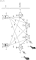
- FIG. 1 shows an example of a wireless communication system to which technical features of the present invention can be applied.
- FIG. 1 shows a system architecture based on an evolved-UMTS terrestrial radio access network (E-UTRAN).
- E-UTRAN evolved-UMTS terrestrial radio access network
- the aforementioned LTE is a part of an evolved-UTMS (e-UMTS) using the E-UTRAN.
- e-UMTS evolved-UTMS
- the wireless communication system includes one or more user equipment (UE; 10), an E-UTRAN and an evolved packet core (EPC).
- the UE 10 refers to a communication equipment carried by a user.
- the UE 10 may be fixed or mobile.
- the UE 10 may be referred to as another terminology, such as a mobile station (MS), a user terminal (UT), a subscriber station (SS), a wireless device, etc.
- the E-UTRAN consists of one or more base station (BS) 20.
- the BS 20 provides the E-UTRA user plane and control plane protocol terminations towards the UE 10.
- the BS 20 is generally a fixed station that communicates with the UE 10.
- the BS 20 hosts the functions, such as inter-cell radio resource management (MME), radio bearer (RB) control, connection mobility control, radio admission control, measurement configuration/provision, dynamic resource allocation (scheduler), etc.
- MME inter-cell radio resource management
- RB radio bearer
- connection mobility control such as connection mobility control, radio admission control, measurement configuration/provision, dynamic resource allocation (scheduler), etc.
- the BS may be referred to as another terminology, such as an evolved NodeB (eNB), a base transceiver system (BTS), an access point (AP), etc.
- eNB evolved NodeB
- BTS base transceiver system
- AP access point
- a downlink (DL) denotes communication from the BS 20 to the UE 10.
- An uplink (UL) denotes communication from the UE 10 to the BS 20.
- a sidelink (SL) denotes communication between the UEs 10.
- a transmitter may be a part of the BS 20, and a receiver may be a part of the UE 10.
- the transmitter may be a part of the UE 10
- the receiver may be a part of the BS 20.
- the transmitter and receiver may be a part of the UE 10.
- the EPC includes a mobility management entity (MME), a serving gateway (S-GW) and a packet data network (PDN) gateway (P-GW).
- MME hosts the functions, such as non-access stratum (NAS) security, idle state mobility handling, evolved packet system (EPS) bearer control, etc.
- NAS non-access stratum
- EPS evolved packet system
- the S-GW hosts the functions, such as mobility anchoring, etc.
- the S-GW is a gateway having an E-UTRAN as an endpoint.
- MME/S-GW 30 will be referred to herein simply as a "gateway," but it is understood that this entity includes both the MME and S-GW.
- the P-GW hosts the functions, such as UE Internet protocol (IP) address allocation, packet filtering, etc.
- IP Internet protocol
- the P-GW is a gateway having a PDN as an endpoint.
- the P-GW is connected to an external network.
- the UE 10 is connected to the BS 20 by means of the Uu interface.
- the UEs 10 are interconnected with each other by means of the PC5 interface.
- the BSs 20 are interconnected with each other by means of the X2 interface.
- the BSs 20 are also connected by means of the S1 interface to the EPC, more specifically to the MME by means of the S1-MME interface and to the S-GW by means of the S1-U interface.
- the S1 interface supports a many-to-many relation between MMEs / S-GWs and BSs.
- FIG. 2 shows another example of a wireless communication system to which technical features of the present invention can be applied.
- FIG. 2 shows a system architecture based on a 5G new radio access technology (NR) system.
- the entity used in the 5G NR system (hereinafter, simply referred to as "NR") may absorb some or all of the functions of the entities introduced in FIG. 1 (e.g. eNB, MME, S-GW).
- the entity used in the NR system may be identified by the name "NG" for distinction from the LTE/LTE-A.
- the wireless communication system includes one or more UE 11, a next-generation RAN (NG-RAN) and a 5th generation core network (5GC).
- the NG-RAN consists of at least one NG-RAN node.
- the NG-RAN node is an entity corresponding to the BS 10 shown in FIG. 1 .
- the NG-RAN node consists of at least one gNB 21 and/or at least one ng-eNB 22.
- the gNB 21 provides NR user plane and control plane protocol terminations towards the UE 11.
- the ng-eNB 22 provides E-UTRA user plane and control plane protocol terminations towards the UE 11.
- the 5GC includes an access and mobility management function (AMF), a user plane function (UPF) and a session management function (SMF).
- AMF hosts the functions, such as NAS security, idle state mobility handling, etc.
- the AMF is an entity including the functions of the conventional MME.
- the UPF hosts the functions, such as mobility anchoring, protocol data unit (PDU) handling.
- PDU protocol data unit
- the UPF an entity including the functions of the conventional S-GW.
- the SMF hosts the functions, such as UE IP address allocation, PDU session control.
- the gNBs and ng-eNBs are interconnected with each other by means of the Xn interface.
- the gNBs and ng-eNBs are also connected by means of the NG interfaces to the 5GC, more specifically to the AMF by means of the NG-C interface and to the UPF by means of the NG-U interface.
- layers of a radio interface protocol between the UE and the network may be classified into a first layer (L1), a second layer (L2), and a third layer (L3) based on the lower three layers of the open system interconnection (OSI) model that is well-known in the communication system.
- OSI open system interconnection
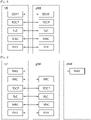
- FIG. 3 shows a block diagram of a user plane protocol stack to which technical features of the present invention can be applied.
- FIG. 4 shows a block diagram of a control plane protocol stack to which technical features of the present invention can be applied.
- the user/control plane protocol stacks shown in FIG. 3 and FIG. 4 are used in NR.
- user/control plane protocol stacks shown in FIG. 3 and FIG .4 may be used in LTE/LTE-A without loss of generality, by replacing gNB/AMF with eNB/ MME.
- the PHY layer offers information transfer services to media access control (MAC) sublayer and higher layers.
- the PHY layer offers to the MAC sublayer transport channels. Data between the MAC sublayer and the PHY layer is transferred via the transport channels.
- MAC media access control
- the MAC sublayer belongs to L2.
- the main services and functions of the MAC sublayer include mapping between logical channels and transport channels, multiplexing/de-multiplexing of MAC service data units (SDUs) belonging to one or different logical channels into/from transport blocks (TB) delivered to/from the physical layer on transport channels, scheduling information reporting, error correction through hybrid automatic repeat request (HARQ), priority handling between UEs by means of dynamic scheduling, priority handling between logical channels of one UE by means of logical channel prioritization (LCP), etc.
- the MAC sublayer offers to the radio link control (RLC) sublayer logical channels.
- RLC radio link control
- the RLC sublayer belong to L2.
- the RLC sublayer supports three transmission modes, i.e. transparent mode (TM), unacknowledged mode (UM), and acknowledged mode (AM), in order to guarantee various quality of services (QoS) required by radio bearers.
- TM transparent mode
- UM unacknowledged mode
- AM acknowledged mode
- the main services and functions of the RLC sublayer depend on the transmission mode.
- the RLC sublayer provides transfer of upper layer PDUs for all three modes, but provides error correction through ARQ for AM only.
- LTE/LTE-A the RLC sublayer provides concatenation, segmentation and reassembly of RLC SDUs (only for UM and AM data transfer) and re-segmentation of RLC data PDUs (only for AM data transfer).
- the RLC sublayer provides segmentation (only for AM and UM) and re-segmentation (only for AM) of RLC SDUs and reassembly of SDU (only for AM and UM). That is, the NR does not support concatenation of RLC SDUs.
- the RLC sublayer offers to the packet data convergence protocol (PDCP) sublayer RLC channels.
- PDCP packet data convergence protocol
- the PDCP sublayer belong to L2.
- the main services and functions of the PDCP sublayer for the user plane include header compression and decompression, transfer of user data, duplicate detection, PDCP PDU routing, retransmission of PDCP SDUs, ciphering and deciphering, etc.
- the main services and functions of the PDCP sublayer for the control plane include ciphering and integrity protection, transfer of control plane data, etc.
- the service data adaptation protocol (SDAP) sublayer belong to L2.
- the SDAP sublayer is only defined in the user plane.
- the SDAP sublayer is only defined for NR.
- the main services and functions of SDAP include, mapping between a QoS flow and a data radio bearer (DRB), and marking QoS flow ID (QFI) in both DL and UL packets.
- the SDAP sublayer offers to 5GC QoS flows.
- a radio resource control (RRC) layer belongs to L3.
- the RRC layer is only defined in the control plane.
- the RRC layer controls radio resources between the UE and the network.
- the RRC layer exchanges RRC messages between the UE and the BS.
- the main services and functions of the RRC layer include broadcast of system information related to AS and NAS, paging, establishment, maintenance and release of an RRC connection between the UE and the network, security functions including key management, establishment, configuration, maintenance and release of radio bearers, mobility functions, QoS management functions, UE measurement reporting and control of the reporting, NAS message transfer to/from NAS from/to UE.
- the RRC layer controls logical channels, transport channels, and physical channels in relation to the configuration, reconfiguration, and release of radio bearers.
- a radio bearer refers to a logical path provided by L1 (PHY layer) and L2 (MAC/RLC/PDCP/SDAP sublayer) for data transmission between a UE and a network.
- Setting the radio bearer means defining the characteristics of the radio protocol layer and the channel for providing a specific service, and setting each specific parameter and operation method.
- Radio bearer may be divided into signaling RB (SRB) and data RB (DRB).
- SRB signaling RB
- DRB data RB
- An RRC state indicates whether an RRC layer of the UE is logically connected to an RRC layer of the E-UTRAN.
- RRC_CONNECTED when the RRC connection is established between the RRC layer of the UE and the RRC layer of the E-UTRAN, the UE is in the RRC connected state (RRC_CONNECTED). Otherwise, the UE is in the RRC idle state (RRC_IDLE).
- RRC_INACTIVE is additionally introduced.
- RRC_INACTIVE may be used for various purposes. For example, the massive machine type communications (MMTC) UEs can be efficiently managed in RRC_INACTIVE. When a specific condition is satisfied, transition is made from one of the above three states to the other.
- a predetermined operation may be performed according to the RRC state.
- RRC_IDLE public land mobile network (PLMN) selection, broadcast of system information (SI), cell re-selection mobility, core network (CN) paging and discontinuous reception (DRX) configured by NAS may be performed.
- PLMN public land mobile network
- SI system information
- CN core network
- DRX discontinuous reception
- the UE shall have been allocated an identifier (ID) which uniquely identifies the UE in a tracking area. No RRC context stored in the base station.
- the UE has an RRC connection with the network (i.e. E-UTRAN/NG-RAN).
- Network-CN connection (both C/U-planes) is also established for UE.
- the UE AS context is stored in the network and the UE.
- the RAN knows the cell which the UE belongs to.
- the network can transmit and/or receive data to/from UE.
- Network controlled mobility including measurement is also performed.
- RRC_IDLE Most of operations performed in RRC_IDLE may be performed in RRC_INACTIVE. But, instead of CN paging in RRC_IDLE, RAN paging is performed in RRC_INACTIVE. In other words, in RRC_IDLE, paging for mobile terminated (MT) data is initiated by core network and paging area is managed by core network. In RRC_INACTIVE, paging is initiated by NG-RAN, and RAN-based notification area (RNA) is managed by NG-RAN. Further, instead of DRX for CN paging configured by NAS in RRC_IDLE, DRX for RAN paging is configured by NG-RAN in RRC_INACTIVE.
- DRX for CN paging configured by NAS in RRC_IDLE
- DRX for RAN paging is configured by NG-RAN in RRC_INACTIVE.
- 5GC-NG-RAN connection (both C/U-planes) is established for UE, and the UE AS context is stored in NG-RAN and the UE.
- NG-RAN knows the RNA which the UE belongs to.
- the NAS layer is located at the top of the RRC layer.
- the NAS control protocol performs the functions, such as authentication, mobility management, security control.
- the physical channels may be modulated according to OFDM processing and utilizes time and frequency as radio resources.
- the physical channels consist of a plurality of orthogonal frequency division multiplexing (OFDM) symbols in time domain and a plurality of subcarriers in frequency domain.
- One subframe consists of a plurality of OFDM symbols in the time domain.
- a resource block is a resource allocation unit, and consists of a plurality of OFDM symbols and a plurality of subcarriers.
- each subframe may use specific subcarriers of specific OFDM symbols (e.g. first OFDM symbol) of the corresponding subframe for a physical downlink control channel (PDCCH), i.e. L1/L2 control channel.
- a transmission time interval (TTI) is a basic unit of time used by a scheduler for resource allocation. The TTI may be defined in units of one or a plurality of slots, or may be defined in units of mini-slots.
- DL transport channels include a broadcast channel (BCH) used for transmitting system information, a downlink shared channel (DL-SCH) used for transmitting user traffic or control signals, and a paging channel (PCH) used for paging a UE.
- DL transport channels include an uplink shared channel (UL-SCH) for transmitting user traffic or control signals and a random access channel (RACH) normally used for initial access to a cell.
- BCH broadcast channel
- DL-SCH downlink shared channel
- PCH paging channel
- UL transport channels include an uplink shared channel (UL-SCH) for transmitting user traffic or control signals and a random access channel (RACH) normally used for initial access to a cell.
- RACH random access channel
- Each logical channel type is defined by what type of information is transferred.
- Logical channels are classified into two groups: control channels and traffic channels.
- Control channels are used for the transfer of control plane information only.
- the control channels include a broadcast control channel (BCCH), a paging control channel (PCCH), a common control channel (CCCH) and a dedicated control channel (DCCH).
- BCCH is a DL channel for broadcasting system control information.
- PCCH is DL channel that transfers paging information, system information change notifications.
- the CCCH is a channel for transmitting control information between UEs and network. This channel is used for UEs having no RRC connection with the network.
- the DCCH is a point-to-point bi-directional channel that transmits dedicated control information between a UE and the network. This channel is used by UEs having an RRC connection.
- Traffic channels are used for the transfer of user plane information only.
- the traffic channels include a dedicated traffic channel (DTCH).
- DTCH is a point-to-point channel, dedicated to one UE, for the transfer of user information.
- the DTCH can exist in both UL and DL.
- BCCH in DL, BCCH can be mapped to BCH, BCCH can be mapped to DL-SCH, PCCH can be mapped to PCH, CCCH can be mapped to DL-SCH, DCCH can be mapped to DL-SCH, and DTCH can be mapped to DL-SCH.
- CCCH can be mapped to UL-SCH
- DCCH can be mapped to UL-SCH
- DTCH can be mapped to UL-SCH.
- Sidelink is described.
- Sidelink is a UE to UE interface for sidelink communication, vehicle-to-everything (V2X) sidelink communication and sidelink discovery.
- the Sidelink corresponds to the PC5 interface.
- Sidelink transmissions are defined for sidelink discovery, sidelink communication and V2X sidelink communication between UEs.
- the sidelink transmissions use the same frame structure as the frame structure that is defined for UL and DL when UEs are in network coverage. However, the sidelink transmission are restricted to a sub-set of the UL resources in time and frequency domain.
- Various physical channels, transport channels and logical channels may be defined for sidelink transmission.
- Sidelink communication is a mode of communication whereby UEs can communicate with each other directly over the PC5 interface. This communication mode is supported when the UE is served by E-UTRAN and when the UE is outside of E-UTRA coverage. Only those UEs authorized to be used for public safety operation can perform sidelink communication.
- the terminology "sidelink communication" without “V2X" prefix may only concern public safety unless specifically stated otherwise.
- the UE performs sidelink communication on subframes defined over the duration of sidelink control (SC) period.
- SC sidelink control
- the SC period is the period over which resources allocated in a cell for sidelink control information (SCI) and sidelink data transmissions occur.
- SCI sidelink control information
- the UE sends SCI followed by sidelink data.
- SCI indicates a Layer 1 ID and characteristics of the transmissions (e.g. modulation and coding scheme (MCS), location of the resource(s) over the duration of SC period, timing alignment).
- MCS modulation and coding scheme
- the UE supporting sidelink communication can operate in two modes for resource allocation.
- the first mode is a scheduled resource allocation, which may be referred to as "Mode 1" for resource allocation of sidelink communication.
- the UE needs to be RRC_CONNECTED in order to transmit data.
- the UE requests transmission resources from the BS.
- the BS schedules transmission resources for transmission of sidelink control information and sidelink data.
- the UE sends a scheduling request (dedicated scheduling request (D-SR) or random access) to the BS followed by a sidelink buffer status report (BSR).
- D-SR dedicated scheduling request
- BSR sidelink buffer status report
- the BS can determine that the UE has data for a sidelink communication transmission and estimate the resources needed for transmission.
- the BS can schedule transmission resources for sidelink communication using configured sidelink radio network temporary identity (SL-RNTI).
- SL-RNTI configured sidelink radio network temporary identity
- the second mode is a UE autonomous resource selection, which may be referred to as "Mode 2" for resource allocation of sidelink communication.
- Mode 2 a UE autonomous resource selection
- a UE on its own selects resources from resource pools and performs transport format selection to transmit sidelink control information and data.
- Each pool can have one or more ProSe per-packet priority (PPPP) associated with it.
- PPPP ProSe per-packet priority
- a UE in RRC_CONNECTED may send a sidelink UE information message to BS when UE becomes interested in sidelink communication.
- BS may configure the UE with a SL-RNTI.
- a UE is considered in-coverage for sidelink communication whenever it detects a cell on a public safety ProSe carrier. If the UE is out of coverage for sidelink communication, it can only use the Mode 2. If the UE is in coverage for sidelink communication, it may use the Mode 1 or the Mode 2 as per BS configuration. If the UE is in coverage for sidelink communication, it shall use only the resource allocation mode indicated by BS configuration, unless one of the exceptional cases occurs. When an exceptional case occurs, the UE is allowed to use the Mode 2 temporarily, even though it was configured to use the Mode 1. Resource pool to be used during exceptional case may be provided by BS.
- a set of transmission and reception resource pools for SCI information when the UE is out of coverage for sidelink communication is pre-configured in the UE.
- the resource pools for SCI when the UE is in coverage for sidelink communication are configured as follows.
- the resource pools used for reception are configured by the BS via RRC, in broadcast signaling.
- the resource pool used for transmission is configured by the BS via RRC, in dedicated or broadcast signaling, if the Mode 2 is used.
- the resource pool used for transmission is configured by the BS via RRC, in dedicated signaling if the Mode 1 is used. In this case, the BS schedules the specific resource(s) for SCI transmission within the configured reception pools.
- a set of transmission and reception resource pools for data when the UE is out of coverage for sidelink communication is pre-configured in the UE.
- the resource pools for data when the UE is in coverage for sidelink communication are configured as follows.
- the resource pools used for transmission and reception are configured by the BS via RRC, in dedicated or broadcast signaling, if the Mode 2 is used. There is no resource pool for transmission and reception if the Mode 1 is used.
- V2X services and V2X sidelink communication is described.
- V2X services can consist of the following four different types, i.e. vehicle-to-vehicle (V2V), vehicle-to-infrastructure (V2I), vehicle-to-nomadic (V2N) and vehicle-to-pedestrian (V2P).
- V2X services can be provided by PC5 interface and/or Uu interface.
- Support of V2X services via PC5 interface is provided by V2X sidelink communication, which is a mode of communication whereby UEs can communicate with each other directly over the PC5 interface. This communication mode is supported when the UE is served by E-UTRAN and when the UE is outside of E-UTRA coverage. Only the UEs authorized to be used for V2X services can perform V2X sidelink communication.
- the UE supporting V2X sidelink communication can operate in two modes for resource allocation.
- the first mode is a scheduled resource allocation, which may be referred to as "Mode 3" for resource allocation of V2X sidelink communication.
- Mode 3 the UE needs to be RRC_CONNECTED in order to transmit data.
- the UE requests transmission resources from the BS.
- the BS schedules transmission resources for transmission of sidelink control information and data.
- Sidelink semi-persistent scheduling (SPS) is supported for the Mode 3.
- SPS Sidelink semi-persistent scheduling
- the second mode is a UE autonomous resource selection, which may be referred to as "Mode 4" for resource allocation of V2X sidelink communication.
- Mode 4 the UE on its own selects resources from resource pools and performs transport format selection to transmit sidelink control information and data. If mapping between the zones and V2X sidelink transmission resource pools is configured, the UE selects V2X sidelink resource pool based on the zone UE is located in. The UE performs sensing for (re)selection of sidelink resources. Based on sensing results, the UE (re)selects some specific sidelink resources and reserves multiple sidelink resources. Up to 2 parallel independent resource reservation processes are allowed to be performed by the UE. The UE is also allowed to perform a single resource selection for its V2X sidelink transmission.
- transmission resource pool configurations including exceptional transmission resource pool for the target cell can be signaled in the handover command to reduce the transmission interruption.
- the UE may use the transmission sidelink resource pools of the target cell before the handover is completed, as long as either synchronization is performed with the target cell in case BS is configured as synchronization source or synchronization is performed with global navigation satellite system (GNSS) in case GNSS is configured as synchronization source.
- GNSS global navigation satellite system
- the exceptional transmission resource pool is included in the handover command, the UE starts using randomly selected resources from the exceptional transmission resource pool starting from the reception of handover command.
- the UE may select resources in the exceptional pool provided in serving cell's SIB21 based on random selection, and uses them temporarily. During cell reselection, the RRC_IDLE UE may use the randomly selected resources from the exceptional transmission resource pool of the reselected cell until the sensing results on the transmission resource pools for the Mode 4 are available.
- RLF radio link failure
- the RRC_IDLE UE may use the randomly selected resources from the exceptional transmission resource pool of the reselected cell until the sensing results on the transmission resource pools for the Mode 4 are available.
- synchronization configuration and reception resource pool configuration for the target cell can be signaled to RRC_CONNECTED UEs in the handover command.
- RRC_IDLE UE it is up to UE implementation to minimize sidelink transmission/reception interruption time associated with acquisition of SIB21 of the target cell.
- a UE is considered in-coverage on the carrier used for V2X sidelink communication whenever it detects a cell on that carrier. If the UE that is authorized for V2X sidelink communication is in-coverage for V2X sidelink communication, it may use the Mode 3 or the Mode 4 as per BS configuration. A set of transmission and reception resource pools when the UE is out of coverage for V2X sidelink communication may be pre-configured in the UE. V2X sidelink communication resources are not shared with other non-V2X data transmitted over sidelink.
- An RRC_CONNECTED UE may send a sidelink UE information message to the serving cell if it is interested in V2X sidelink communication transmission in order to request sidelink resources.
- the UE receives on those provided resources.
- Reception of sidelink V2X communication in different carriers/PLMNs can be supported by having multiple receiver chains in the UE.
- SPS For sidelink SPS, maximum 8 SPS configurations with different parameters can be configured by BS and all SPS configurations can be active at the same time.
- the activation/deactivation of SPS configuration is signalled via PDCCH by BS.
- the existing logical channel prioritization based on PPPP is used for sidelink SPS.
- UE assistance information can be provided to BS. Reporting of UE assistance information is configured by BS for V2X sidelink communication.
- the UE assistance information used for V2X sidelink communication includes traffic characteristic parameters (e.g. a set of preferred expected SPS interval, timing offset with respect to subframe 0 of the system frame number (SFN) 0, PPPP and maximum transport block (TB) size based on observed traffic pattern) related to the SPS configuration.
- the UE assistance information can be reported in case either SPS is already configured or not. Triggering of UE assistance information transmission is left to UE implementation. For instance, the UE is allowed to report UE assistance information when change in estimated periodicity and/or timing offset of packet arrival occurs.
- SR mask per traffic type is not supported for V2X sidelink communication.
- the network is able to indicate how the UE adapts its transmission parameters for each transmission pool depending on the channel busy ratio (CBR).
- CBR channel busy ratio
- the UE measures all the configured transmission pools including exceptional pool. Only data pool is measured for the case scheduling assignment (SA) pool and data pool resources are located adjacently, while SA pool and data pool is measured separately for the case SA pool and data pool are located non-adjacently.
- SA case scheduling assignment
- a UE in RRC_CONNECTED can be configured to report CBR measurement results.
- CBR reporting periodic reporting and event triggered reporting are supported. Two new reporting events defined only for the data pool are introduced for event-triggered CBR reporting.
- CBR event-triggered reporting is triggered by overloaded threshold and/or less-loaded threshold.
- the network can configure which of the transmission pools the UE needs to report.
- a UE (regardless of its RRC state) performs transmission parameter adaptation based on the CBR.
- the exemplary adapted transmission parameters include maximum transmission power, range of the number of retransmission per TB, range of physical sidelink shared channel (PSSCH) resource block number, range of MCS, maximum limit on channel occupancy ratio.
- PSSCH physical sidelink shared channel
- the transmission parameter adaption applies to all transmission pools including exceptional pool.
- Sidelink transmission and/or reception resources including exceptional pool for different frequencies for the Mode 3 and Mode 4 may be provided.
- the sidelink resources for different frequencies can be provided via dedicated signaling, SIB21 and/ or pre-configuration.
- the serving cell may indicate to the UE only the frequency on which the UE may acquire the sidelink resource configuration. If multiple frequencies and associated resource information are provided, it is up to UE implementation to select the frequency among the provided frequencies.
- the UE shall not use pre-configured transmission resource if the UE detects a cell providing resource configuration or inter-carrier resource configuration for V2X sidelink communication. Frequencies which may provide V2X sidelink communication resource configuration or cross-carrier configuration can be pre-configured.
- the RRC_IDLE UE may prioritize the frequency that provides resource configuration for V2X sidelink communication for other carrier during cell reselection.
- the UE may simultaneously transmit on multiple carriers via PC5.
- a mapping between service types and V2X frequencies is configured by upper layers. The UE should ensure a service to be transmitted on the corresponding frequency.
- the UE may receive the V2X sidelink communication of other PLMNs.
- the serving cell can indicate to the UE the RX resource configuration for inter-PLMN operation directly or only the frequency on which the UE may acquire the inter-PLMN sidelink resource configuration. Sidelink transmission in other PLMNs is not allowed.
- the UE When UL transmission overlaps in time domain with V2X sidelink transmission in the same frequency, the UE prioritizes the sidelink transmission over the UL transmission if the PPPP of sidelink MAC PDU is lower than a (pre)configured PPPP threshold.
- the UE may prioritize the sidelink transmission over the UL transmission or reduce UL transmission power if the PPPP of sidelink MAC PDU is lower than a (pre)configured PPPP threshold.
- the UE if UL transmission is prioritized by upper layer or RACH procedure is performed, the UE prioritizes UL transmission over any V2X sidelink transmission (i.e. irrespectively of the sidelink MAC PDU's PPPP).
- the MAC entity In order to transmit on the sidelink shared channel (SL-SCH), the MAC entity must have at least one sidelink grant.
- SL-SCH sidelink shared channel
- the MAC entity shall for each subframe:
- a resource pool is configured only on a single carrier.
- a UE RRC i.e. the RRC layer of the UE
- UE MAC i.e. the MAC layer of the UE
- resource (re-)selection on the selected pool if UE performs parallel transmissions on different carriers, the UE will independently select resources on each carrier. In this case, the UE may perform parallel sidelink transmissions on congested carriers, so that increase congestion on those carriers.
- CA Carrier aggregation
- V2X sidelink communication In release 15, Carrier aggregation (CA) in sidelink is supported for V2X sidelink communication. It applies to both in coverage UEs and out of coverage UEs.
- CA in sidelink neither primary component carrier nor secondary component carriers are defined.
- Each resource pool (pre)configured for V2X sidelink communication transmission or reception is associated to a single carrier.
- a UE supporting CA in sidelink uses autonomous resource selection, it performs carrier selection and may select one or more carriers used for V2X sidelink communication transmission.
- the carrier selection is performed at MAC layer, depending on the CBR of the (pre)configured carriers for V2X sidelink communication and the PPPP(s) of the V2X messages to be transmitted.
- the carrier reselection may be performed when resource reselection is triggered and is triggered for each sidelink process.
- the UE may keep using a carrier already selected for transmission, if the measured CBR on this carrier is lower than a (pre)configured threshold.
- logical channel prioritization is performed for a sidelink resource on a carrier depending on the CBR measured on the carrier and the PPPP of the sidelink logical channels as specified in 3GPP TS 36.321 [13].
- the UE may select carriers or multiple resource pools of which CBR value is below a threshold indicated by the network among the configured carriers or resource pools. Then, the UE may select sidelink resources (i.e. sidelink grants) on some or all of the selected carriers or the selected resource pools to transmit one or more MAC PDUs.
- sidelink resources i.e. sidelink grants
- the UE may select sidelink resources (i.e. sidelink grants) on all of the configured carriers or resource pools. Then, UE may allocate only sidelink resources of particular carriers or resource pools to sidelink logical channels in the Logical Channel Prioritization procedure.
- the particular carrier or resource pool may provide a CBR value below the threshold indicated by the network.
- the UE may monitor the selected carriers or the selected resource pools to receive one or more MAC PDUs.
- the network may indicate to UE which resource pools can be aggregated in sidelink can be aggregated in sidelink e.g. via system information and/or a dedicated signaling.
- the network may indicate information to the UE described as below:
- the UE may (randomly) select one or more carriers of which CBR value is below the threshold among the indicated carriers.
- the UE may know the CBR level of each carrier either by measuring CBR by a lower layer on the carrier or by receiving a CBR value from a cell.
- the UE may select a carrier with the lowest CBR value in an increasing order of the CBR value among the carriers of which CBR value is equal to or above the threshold.
- the UE may select sidelink resources on the selected carrier(s) and then transmit SCI (Sidelink Control Information) and/or data on the selected sidelink resources.
- the sidelink resource may correspond to a sidelink logical channel.
- the UE may monitor or receive SCI (Sidelink Control Information) on the selected carrier(s). Then, the UE may receive data on the carrier(s) indicated by the SCI.
- SCI Servicelink Control Information
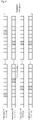
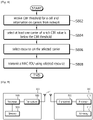
- Fig. 5 shows a flow chart of a method for selecting carriers according to an embodiment of the present invention. Following steps are details about how the UE selects one or more carriers.
- carriers may be replaced by resource pools, because each resource pool is associated to a single carrier.
- the network may indicate CBR threshold for a cell and information on carriers.
- the network may indicate 0.3 as the CBR threshold for the cell, and the network may indicate carrier #1, carrier #2, carrier #3 and carrier #4.
- the UE may acquire CBR value of the carriers indicated by the network.
- the UE may acquire CBR value of carrier #1, carrier #2, carrier #3 and carrier #4.
- the UE camping on the cell or the UE served by the cell may perform measurement on the carriers.
- the UE may receive a CBR value for each carrier from the network.
- the acquired CBR value of each carrier as below.
- the UE may determine how many carriers should be selected e.g. based on the amount of data available for transmission in L2 buffer. According to an embodiment of the present invention, the UE may determine that 3 carriers should be selected.
- the UE may select carriers of which CBR value is below the CBR threshold indicated by the network.
- the CBR threshold indicated by the network may be 0.3. In this case, UE selects carrier #2 of which CBR value is 0.1, and carrier #3 of which CBR value is 0.2.
- the UE may select additional carriers.
- the additional carriers may be carriers of which CBR value that is equal to or above the CBR threshold.
- the number of the additional carriers may be a difference between the number of carriers of which CBR value is below the CBR threshold and the number of carriers which is determined to be selected. According to the exemplary embodiments, even though the UE needs to select 3 carriers in total, but the UE selected only 2 carriers in step S508. Thus, the UE may select an additional carrier of which CBR value is equal to or above 0.3.
- the additional carriers may be selected in order of increasing CBR value. That is, a priority among the carriers is configured based on each CBR value. Since carrier #1 provides the lowest CBR value among the carriers of which CBR value is above 0.3, UE may select carrier #1.
- the UE may select any carrier of which CBR value is below the CBR threshold.
- the UE may select randomly carrier(s) among carriers of which CBR value is below the CBR threshold, or select carrier(s) in the order of CBR value of a carrier among carriers of which CBR value is below the CBR threshold.
- the UE may select resources on each selected carrier.
- the resources mentioned in this step may be sidelink resources.
- the UE may select resources on each of carrier #1, carrier #2 and carrier #3. Namely, the UE may not select resources on non-selected carrier which is configured by RRC.
- the UE may occupy data on each carrier in the order of CBR value of a carrier.
- the UE may occupy data on each carrier in order from lowest CBR value to higher CBR value.
- the UE may occupy carrier #2 at first. Then, if UE has remaining data to be transmitted, especially in sidelink, the UE may occupy carrier #3. Finally, if UE still has remaining data to be transmitted, the UE may occupy carrier #1.
- the UE may transmit SCI and data on the selected resources of carrier #1, carrier #2 and carrier #3.
- step S5166 whenever data becomes available for transmission in L2 buffer, the UE may determine how many carrier should be selected e.g. based on the amount of data available for transmission in L2 buffer. For example, the UE may determine that 1 carrier should be selected. In this case, the UE may select one carrier of which CBR value is below 0.3. Thus, the UE may randomly select one of carrier #2 and carrier #3. Further, the UE may select sidelink resources on the selected carrier. Then, UE may transmit SCI and data on the selected resources of the selected carrier. In this way, the steps described above may be repeated.
- the UE may determine how many carrier should be selected e.g. based on the amount of data available for transmission in L2 buffer. For example, the UE may determine that 1 carrier should be selected. In this case, the UE may select one carrier of which CBR value is below 0.3. Thus, the UE may randomly select one of carrier #2 and carrier #3. Further, the UE may select sidelink resources on the selected carrier. Then, UE may transmit SCI
- selecting carrier may indicate that the UE may also select a resource pool which is associated to the carrier.
- Fig. 6 shows an example of a method for selecting carriers according to an embodiment of the present invention.
- the network may indicate a CBR threshold for a cell and information on carriers.
- the network may indicate 0.3 as the CBR threshold for the cell, and the network may indicate carrier #1, carrier #2, carrier #3 and carrier #4.
- the carrier #1 may correspond to resource pool #1
- the carrier #2 may correspond to resource pool #2
- the carrier #3 may correspond to resource pool #3
- the carrier #4 may correspond to resource pool #4.
- the indicated carriers provide CBR values as follow.
- the UE may select carriers of which CBR value is below the CBR threshold. If the UE determined that 2 carriers should be selected e.g. based on the amount of data available for transmission in L2 buffer, then the UE may select carrier #2 and carrier #3. On the other hand, if the UE determined that only 1 carrier should be selected, the UE may select carrier in the order of CBR value of carrier. In specific, the UE may occupy data on each carrier in order from lowest CBR value to higher CBR value. In the embodiment of the present invention, the UE may select carrier #2 which provides smaller CBR value.
- Fig. 7 shows an example of a method for selecting carriers according to an embodiment of the present invention.
- a resource pool mentioned above can be replaced by a SPS configuration or a set of allocated resources of an activated SPS configuration. That is, the carrier #1 may correspond to a SPS configuration #1, the carrier #2 may correspond to a SPS configuration #2, the carrier #3 may correspond to a SPS configuration #3, and the carrier #4 may correspond to a SPS configuration #4.
- the embodiment can be applied to carrier selection for multiple SPS configurations as shown in Fig. 7 .
- UE may (randomly) select one or more carriers or one or more activated SPS configurations of which CBR value is below the threshold among the indicated carriers of the activated SPS configurations, if CBR values are known to UE.
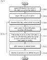
- Fig. 8 shows a flow chart of a method for selecting carriers according to an embodiment of the present invention.
- the UE may receive information on carriers and Channel Busy Ratio threshold from a network.
- the CBR threshold may be provided per UE, per cell, per carrier or per frequency band.
- the UE may select at least one carrier of which CBR value is below the CBR threshold. For that, the UE may measure CBR values of the carriers which are indicated by the network, or receive CBR values of the carriers which are indicated by the network, from the network.
- the at least one carrier may be aggregated carrier separated for reception and transmission.
- step S806 the UE may select a resource on the selected carrier.
- the UE may transmit a medium access control (MAC) packet data unit (PDU) by using the selected resource of the selected carrier.
- MAC medium access control
- PDU packet data unit
- the UE may determine how many carriers to be selected based on an amount of data available for transmission. If a number of carriers determined to be selected is larger than a number of carriers of which CBR value is below the CBR threshold, the UE may select at least one additional carrier among carriers of which CBR value is above the CBR threshold. The UE may select the at least one additional carrier in order of CBR value of the additional carrier.
- a MAC entity of a UE may operate as follow.
- the MAC entity shall consider a CBR of a carrier to be one measured by lower layers according to 3GPP TS 36.214 [6] if CBR measurement results are available, or the corresponding defaultTxConfigIndex configured by upper layers for the carrier if CBR measurement results are not available.
- the MAC entity shall:
- the MAC entity shall:
- a UE 900 includes a processor 901, a memory 902, and a transceiver 903.
- the memory 902 is coupled to the processor 901, and stores a variety of information for driving the processor 901.
- the transceiver 903 is coupled to the processor 901, and transmits and/or receives a radio signal.
- the processor 901 implements the proposed functions, procedures, and/or methods. In the aforementioned embodiments, an operation of the first network node may be implemented by the processor 901.
- a network node 910 includes a processor 911, a memory 912, and a transceiver 913.
- the memory 912 is coupled to the processor 911, and stores a variety of information for driving the processor 911.
- the transceiver 913 is coupled to the processor 911, and transmits and/or receives a radio signal.
- the processor 911 implements the proposed functions, procedures, and/or methods. In the aforementioned embodiments, an operation of the second network node 910 may be implemented by the processor 911.
- the processors 911 may include application-specific integrated circuit (ASIC), other chipset, logic circuit and/or data processing device.
- the memories may include read-only memory (ROM), random access memory (RAM), flash memory, memory card, storage medium and/or other storage device.
- the transceivers may include baseband circuitry to process radio frequency signals.
Landscapes
- Engineering & Computer Science (AREA)
- Signal Processing (AREA)
- Computer Networks & Wireless Communication (AREA)
- Quality & Reliability (AREA)
- Mobile Radio Communication Systems (AREA)
Claims (7)
- Procédé réalisé par un équipement utilisateur, UE, (900) configuré pour utiliser une agrégation de porteuses dans des communications de liaison latérale, le procédé comprenant :l'acquisition (S502) d'informations sur de multiples porteuses pour l'agrégation de porteuses et de multiples seuils de taux d'occupation de canal, CBR, dans lequel chacun des multiples seuils CBR est configuré pour chacune des multiples porteuses ;l'acquisition (S504) d'une valeur de CBR de chacune des multiples porteuses ;la détermination (S506) d'un nombre de porteuses à sélectionner ;la sélection (S508) d'au moins une porteuse candidate, parmi les multiples porteuses,chacune desquelles ayant une valeur de CBR inférieure à un seuil de CBR pour chacune de l'au moins une porteuse candidate ;sur la base du nombre de porteuses à sélectionner qui est plus grand que le nombre de l'au moins une porteuse candidate, la sélection (S510) de l'au moins une porteuse additionnelle, parmi les multiples porteuses, chacune desquelles ayant une valeur de CBR supérieure au seuil de CBR pour chacune de l'au moins une porteuse additionnelle, dans un ordre croissant de la valeur de CBR de l'au moins une porteuse additionnelle ;la sélection (S512) d'une ressource de liaison latérale sur l'au moins une porteuse candidate et une porteuse additionnelle sélectionnée ; etla transmission (S514) d'une unité de données par paquets, PDU, de commande d'accès au support, MAC, sur la base de la ressource de liaison latérale.
- Procédé selon la revendication 1, dans lequel la PDU MAC est associée à une transmission de liaison latérale.
- Procédé selon la revendication 1, dans lequel la valeur de CBR est mesurée par l'UE (900) et/ou est reçue à partir d'un réseau.
- Procédé selon la revendication 1, dans lequel le nombre de porteuses à sélectionner est déterminé sur la base d'une quantité de données disponibles pour la transmission.
- Equipement utilisateur, UE, (900) configuré pour utiliser une agrégation de porteuses dans des communications de liaison latérale, l'UE (900) comprenant :un émetteur-récepteur (930) ; etun processeur (910) couplé à l'émetteur-récepteur (930),dans lequel le processeur (910) est configuré pour :acquérir des informations sur de multiples porteuses pour l'agrégation de porteuses et de multiples seuils de taux d'occupation de canal, CBR, dans lequel chacun des multiples seuils CBR est configuré pour chacune des multiples porteuses ;acquérir une valeur de CBR de chacune des multiples porteuses ;déterminer un nombre de porteuses à sélectionner ;sélectionner au moins une porteuse candidate, parmi les multiples porteuses, chacune desquelles ayant une valeur de CBR inférieure à un seuil de CBR pour chacune de l'au moins une porteuse candidate ;sur la base du nombre de porteuses à sélectionner qui est plus grand que le nombre de l'au moins une porteuse candidate, sélectionner l'au moins une porteuse additionnelle, parmi les multiples porteuses, chacune desquelles ayant une valeur de CBR supérieure au seuil de CBR pour chacune de l'au moins une porteuse additionnelle, dans un ordre croissant de la valeur de CBR de l'au moins une porteuse additionnelle ;sélectionner une ressource de liaison latérale sur l'au moins une porteuse candidate et une porteuse additionnelle sélectionnée ; etcommander l'émetteur-récepteur pour transmettre une unité de données par paquets, PDU, de commande d'accès au support, MAC, sur la base de la ressource de liaison latérale.
- L'UE (900) selon la revendication 5, dans lequel la PDU MAC est associée à une transmission de liaison latérale.
- L'UE (900) selon la revendication 5, dans lequel la valeur de CBR est mesurée par l'UE (900) et/ou est reçue à partir d'un réseau.
Applications Claiming Priority (2)
| Application Number | Priority Date | Filing Date | Title |
|---|---|---|---|
| US201762536977P | 2017-07-25 | 2017-07-25 | |
| PCT/KR2018/008414 WO2019022504A1 (fr) | 2017-07-25 | 2018-07-25 | Procédé de sélection de porteuses, et dispositif prenant en charge le procédé |
Publications (3)
| Publication Number | Publication Date |
|---|---|
| EP3649813A1 EP3649813A1 (fr) | 2020-05-13 |
| EP3649813A4 EP3649813A4 (fr) | 2020-06-24 |
| EP3649813B1 true EP3649813B1 (fr) | 2022-09-07 |
Family
ID=65040807
Family Applications (1)
| Application Number | Title | Priority Date | Filing Date |
|---|---|---|---|
| EP18838817.7A Active EP3649813B1 (fr) | 2017-07-25 | 2018-07-25 | Procédé de sélection de porteuses, et dispositif prenant en charge le procédé |
Country Status (5)
| Country | Link |
|---|---|
| US (1) | US11457429B2 (fr) |
| EP (1) | EP3649813B1 (fr) |
| JP (1) | JP2020529158A (fr) |
| CN (1) | CN110999444A (fr) |
| WO (1) | WO2019022504A1 (fr) |
Cited By (2)
| Publication number | Priority date | Publication date | Assignee | Title |
|---|---|---|---|---|
| WO2024210525A1 (fr) * | 2023-04-05 | 2024-10-10 | Lg Electronics Inc. | Agrégation de porteuses de liaison latérale |
| WO2025034002A1 (fr) * | 2023-08-09 | 2025-02-13 | 엘지전자 주식회사 | Procédé et appareil de sélection d'un groupe de ressources d'un terminal prenant en charge des porteuses multiples |
Families Citing this family (28)
| Publication number | Priority date | Publication date | Assignee | Title |
|---|---|---|---|---|
| JP7101762B6 (ja) * | 2017-09-15 | 2022-09-30 | オッポ広東移動通信有限公司 | キャリア選択方法及び通信装置 |
| CN109691145B (zh) * | 2018-01-18 | 2020-09-22 | Oppo广东移动通信有限公司 | 车联网中的数据传输方法及终端 |
| US11297472B2 (en) * | 2018-02-01 | 2022-04-05 | Hyundai Motor Company | Method and apparatus for load distribution using a plurality of carriers in communication system supporting vehicle-to-everything communication |
| CN115086913B (zh) * | 2018-09-04 | 2024-07-12 | 上海朗帛通信技术有限公司 | 一种被用于无线通信的节点中的方法和装置 |
| CN113660694B (zh) * | 2018-09-18 | 2024-04-12 | 华为技术有限公司 | 传输数据的方法和装置 |
| CN111263451B (zh) * | 2019-01-23 | 2022-10-11 | 维沃移动通信有限公司 | 副链路传输方法和设备 |
| EP3954075B1 (fr) * | 2019-04-08 | 2025-01-29 | Telefonaktiebolaget LM Ericsson (publ) | Procédés fournissant une harq de liaison latérale au niveau d'une strate d'accès et dispositifs sans fil associés |
| US20220209905A1 (en) * | 2019-04-30 | 2022-06-30 | Lenovo (Beijing) Limited | Method and apparatus for sidelink resource allocation |
| CN111988760B (zh) * | 2019-05-22 | 2022-05-24 | 上海朗帛通信技术有限公司 | 一种被用于无线通信的节点中的方法和装置 |
| US11641598B2 (en) * | 2019-06-13 | 2023-05-02 | Qualcomm Incorporated | Device-to-device quality of service flow management |
| CN114097277B (zh) * | 2019-07-04 | 2024-12-06 | 上海诺基亚贝尔股份有限公司 | V2x通信从sidelink连接到小区连接的主动切换 |
| WO2021004621A1 (fr) * | 2019-07-08 | 2021-01-14 | Fraunhofer-Gesellschaft zur Förderung der angewandten Forschung e.V. | Conception de groupe exceptionnel amélioré pour liaison latérale v2x nr |
| WO2021066407A1 (fr) | 2019-10-03 | 2021-04-08 | Lg Electronics Inc. | Procédé et appareil pour réaliser une retransmission dans un système de communication sans fil |
| CN120091404B (zh) * | 2020-02-18 | 2026-03-10 | 华为技术有限公司 | 通信方法及装置 |
| WO2021185957A1 (fr) * | 2020-03-20 | 2021-09-23 | Fraunhofer-Gesellschaft zur Förderung der angewandten Forschung e.V. | Allocation de ressource de réception discontinue de liaison latérale nr |
| CN111869245B (zh) * | 2020-06-17 | 2023-11-21 | 北京小米移动软件有限公司 | 直连通信方法、装置及存储介质 |
| FI20205694A1 (en) * | 2020-06-29 | 2021-12-30 | Nokia Technologies Oy | Improved carrier selection |
| WO2022084089A1 (fr) * | 2020-10-22 | 2022-04-28 | Sony Group Corporation | Procédé de communication de dispositif à dispositif |
| WO2022150972A1 (fr) * | 2021-01-12 | 2022-07-21 | Apple Inc. | Sélection de ressource de liaison latérale assistée par réseau |
| WO2022150994A1 (fr) * | 2021-01-12 | 2022-07-21 | Lenovo (Beijing) Limited | Mécanisme de récupération après défaillance de faisceau |
| US20240032077A1 (en) | 2021-03-01 | 2024-01-25 | Qualcomm Incorporated | Carrier aggregation on sidelink |
| EP4420448A4 (fr) * | 2021-10-20 | 2025-01-15 | Telefonaktiebolaget LM Ericsson (publ) | Procédé pour gérer une communication de liaison latérale entre des équipements utilisateur à l'aide d'indications de qualité de supports de liaison latérale |
| WO2023087981A1 (fr) * | 2021-11-19 | 2023-05-25 | Telefonaktiebolaget Lm Ericsson (Publ) | Procédé et appareil de sélection de porteuse de liaison latérale |
| US11956306B1 (en) * | 2022-03-30 | 2024-04-09 | Nvidia Corporation | Multicast-reduction assisted by network devices |
| CN118765529A (zh) * | 2022-08-01 | 2024-10-11 | Oppo广东移动通信有限公司 | 传输资源选取方法和设备 |
| JP2025529682A (ja) * | 2022-08-05 | 2025-09-09 | インターデイジタル パテント ホールディングス インコーポレイテッド | マルチキャリアサイドリンクにおける測定ベースのキャリア選択 |
| WO2024040413A1 (fr) * | 2022-08-22 | 2024-02-29 | 北京小米移动软件有限公司 | Procédé de resélection de ressources, appareil, dispositif, et support de stockage |
| WO2024040475A1 (fr) * | 2022-08-24 | 2024-02-29 | 北京小米移动软件有限公司 | Procédé de maintien de porteuse, et appareil, dispositif et support de stockage |
Family Cites Families (8)
| Publication number | Priority date | Publication date | Assignee | Title |
|---|---|---|---|---|
| WO2010087570A1 (fr) * | 2009-02-02 | 2010-08-05 | Lg Electronics Inc. | Allocation de ressources de canal avec accès aléatoire |
| KR101506598B1 (ko) * | 2013-11-29 | 2015-03-27 | 현대모비스 주식회사 | 차량간 통신을 위한 통신 장치 |
| WO2016163239A1 (fr) * | 2015-04-09 | 2016-10-13 | 株式会社Nttドコモ | Dispositif utilisateur et station de base |
| EP3560261B1 (fr) * | 2016-12-21 | 2023-11-08 | Telefonaktiebolaget LM Ericsson (publ) | Indication d'état its |
| KR102275288B1 (ko) * | 2017-01-03 | 2021-07-09 | 삼성전자 주식회사 | V2X 통신을 위한 inter-carrier 방법 |
| US11102631B2 (en) * | 2017-03-24 | 2021-08-24 | Samsung Electronics Co., Ltd. | Resource selection method in vehicle to everything communication and apparatus therefore |
| CN110583080B (zh) * | 2017-05-04 | 2023-05-30 | 松下电器(美国)知识产权公司 | 用户设备及其方法 |
| CN109151844B (zh) * | 2017-06-15 | 2023-03-24 | 中兴通讯股份有限公司 | 一种终端之间通信的方法、终端和系统 |
-
2018
- 2018-07-25 EP EP18838817.7A patent/EP3649813B1/fr active Active
- 2018-07-25 US US16/634,080 patent/US11457429B2/en active Active
- 2018-07-25 WO PCT/KR2018/008414 patent/WO2019022504A1/fr not_active Ceased
- 2018-07-25 JP JP2020503816A patent/JP2020529158A/ja active Pending
- 2018-07-25 CN CN201880049970.7A patent/CN110999444A/zh active Pending
Non-Patent Citations (1)
| Title |
|---|
| CATT: "Multi-Carrier Operation for Sidelink V2X", vol. RAN WG2, no. Reno, USA; 20161114 - 20161118, 13 November 2016 (2016-11-13), XP051177800, Retrieved from the Internet <URL:http://www.3gpp.org/ftp/Meetings_3GPP_SYNC/RAN2/Docs/> [retrieved on 20161113] * |
Cited By (2)
| Publication number | Priority date | Publication date | Assignee | Title |
|---|---|---|---|---|
| WO2024210525A1 (fr) * | 2023-04-05 | 2024-10-10 | Lg Electronics Inc. | Agrégation de porteuses de liaison latérale |
| WO2025034002A1 (fr) * | 2023-08-09 | 2025-02-13 | 엘지전자 주식회사 | Procédé et appareil de sélection d'un groupe de ressources d'un terminal prenant en charge des porteuses multiples |
Also Published As
| Publication number | Publication date |
|---|---|
| EP3649813A1 (fr) | 2020-05-13 |
| JP2020529158A (ja) | 2020-10-01 |
| US20200169986A1 (en) | 2020-05-28 |
| US11457429B2 (en) | 2022-09-27 |
| EP3649813A4 (fr) | 2020-06-24 |
| CN110999444A (zh) | 2020-04-10 |
| WO2019022504A1 (fr) | 2019-01-31 |
Similar Documents
| Publication | Publication Date | Title |
|---|---|---|
| EP3649813B1 (fr) | Procédé de sélection de porteuses, et dispositif prenant en charge le procédé | |
| US11664933B2 (en) | Method and apparatus for flushing HARQ buffer in wireless communication system | |
| US11051304B2 (en) | Method and apparatus for selecting carrier for sidelink transmission in wireless communication system | |
| US11219035B2 (en) | Method and apparatus for deprioritizing duplicated packet transmission in wireless communication system | |
| JP7186763B2 (ja) | 無線通信システムにおいて複数の搬送波上でサイドリンク送信を行うための方法及び装置 | |
| EP3649817B1 (fr) | Procédé et appareil permettant d'attribuer des ressources basées sur une porteuse d'ancrage dans un système de communication sans fil | |
| US11700666B2 (en) | Method and apparatus for triggering transmission carrier selection in wireless communication system | |
| US11044651B2 (en) | Method and apparatus for supporting carrier reselection based on channel busy ratio in wireless communication system | |
| CN114208084B (zh) | 用于确定无线通信中的harq定时的方法和装置 | |
| US11350309B2 (en) | Method and apparatus for deprioritizing packet transmission based on reliability level or congestion level in wireless communication system | |
| US11184916B2 (en) | Method and apparatus of allocating resource for multiple device-to-device resource pools in a wireless communication system | |
| US20200053699A1 (en) | Method and apparatus for selecting device-to-device resource pool in a wireless communication system | |
| JP7420732B2 (ja) | ユーザ装置および通信システム | |
| KR20190042525A (ko) | 이동통신 시스템에서 랜덤 액세스 절차를 수행하는 방법 및 장치 | |
| KR20190110143A (ko) | 복수의 반송파들이 설정된 단말의 전력 할당 방법 및 상기 방법을 이용하는 단말 | |
| US10805832B2 (en) | Method and apparatus for handling coexistence with DSRC carrier in wireless communication system | |
| US11102708B2 (en) | Method for acquiring changed system information and device supporting the same |
Legal Events
| Date | Code | Title | Description |
|---|---|---|---|
| STAA | Information on the status of an ep patent application or granted ep patent |
Free format text: STATUS: THE INTERNATIONAL PUBLICATION HAS BEEN MADE |
|
| PUAI | Public reference made under article 153(3) epc to a published international application that has entered the european phase |
Free format text: ORIGINAL CODE: 0009012 |
|
| STAA | Information on the status of an ep patent application or granted ep patent |
Free format text: STATUS: REQUEST FOR EXAMINATION WAS MADE |
|
| 17P | Request for examination filed |
Effective date: 20200205 |
|
| AK | Designated contracting states |
Kind code of ref document: A1 Designated state(s): AL AT BE BG CH CY CZ DE DK EE ES FI FR GB GR HR HU IE IS IT LI LT LU LV MC MK MT NL NO PL PT RO RS SE SI SK SM TR |
|
| AX | Request for extension of the european patent |
Extension state: BA ME |
|
| A4 | Supplementary search report drawn up and despatched |
Effective date: 20200525 |
|
| RIC1 | Information provided on ipc code assigned before grant |
Ipc: H04W 92/18 20090101ALI20200516BHEP Ipc: H04W 72/02 20090101AFI20200516BHEP Ipc: H04W 72/04 20090101ALI20200516BHEP Ipc: H04W 36/00 20090101ALI20200516BHEP |
|
| DAV | Request for validation of the european patent (deleted) | ||
| DAX | Request for extension of the european patent (deleted) | ||
| STAA | Information on the status of an ep patent application or granted ep patent |
Free format text: STATUS: EXAMINATION IS IN PROGRESS |
|
| 17Q | First examination report despatched |
Effective date: 20210215 |
|
| GRAP | Despatch of communication of intention to grant a patent |
Free format text: ORIGINAL CODE: EPIDOSNIGR1 |
|
| STAA | Information on the status of an ep patent application or granted ep patent |
Free format text: STATUS: GRANT OF PATENT IS INTENDED |
|
| RIC1 | Information provided on ipc code assigned before grant |
Ipc: H04W 36/00 20090101ALI20220303BHEP Ipc: H04W 92/18 20090101ALI20220303BHEP Ipc: H04W 72/04 20090101ALI20220303BHEP Ipc: H04W 72/02 20090101AFI20220303BHEP |
|
| INTG | Intention to grant announced |
Effective date: 20220323 |
|
| GRAS | Grant fee paid |
Free format text: ORIGINAL CODE: EPIDOSNIGR3 |
|
| GRAA | (expected) grant |
Free format text: ORIGINAL CODE: 0009210 |
|
| STAA | Information on the status of an ep patent application or granted ep patent |
Free format text: STATUS: THE PATENT HAS BEEN GRANTED |
|
| AK | Designated contracting states |
Kind code of ref document: B1 Designated state(s): AL AT BE BG CH CY CZ DE DK EE ES FI FR GB GR HR HU IE IS IT LI LT LU LV MC MK MT NL NO PL PT RO RS SE SI SK SM TR |
|
| REG | Reference to a national code |
Ref country code: GB Ref legal event code: FG4D |
|
| REG | Reference to a national code |
Ref country code: CH Ref legal event code: EP Ref country code: AT Ref legal event code: REF Ref document number: 1518085 Country of ref document: AT Kind code of ref document: T Effective date: 20220915 |
|
| REG | Reference to a national code |
Ref country code: DE Ref legal event code: R096 Ref document number: 602018040463 Country of ref document: DE |
|
| REG | Reference to a national code |
Ref country code: IE Ref legal event code: FG4D |
|
| REG | Reference to a national code |
Ref country code: LT Ref legal event code: MG9D |
|
| REG | Reference to a national code |
Ref country code: NL Ref legal event code: MP Effective date: 20220907 |
|
| PG25 | Lapsed in a contracting state [announced via postgrant information from national office to epo] |
Ref country code: SE Free format text: LAPSE BECAUSE OF FAILURE TO SUBMIT A TRANSLATION OF THE DESCRIPTION OR TO PAY THE FEE WITHIN THE PRESCRIBED TIME-LIMIT Effective date: 20220907 Ref country code: RS Free format text: LAPSE BECAUSE OF FAILURE TO SUBMIT A TRANSLATION OF THE DESCRIPTION OR TO PAY THE FEE WITHIN THE PRESCRIBED TIME-LIMIT Effective date: 20220907 Ref country code: NO Free format text: LAPSE BECAUSE OF FAILURE TO SUBMIT A TRANSLATION OF THE DESCRIPTION OR TO PAY THE FEE WITHIN THE PRESCRIBED TIME-LIMIT Effective date: 20221207 Ref country code: LV Free format text: LAPSE BECAUSE OF FAILURE TO SUBMIT A TRANSLATION OF THE DESCRIPTION OR TO PAY THE FEE WITHIN THE PRESCRIBED TIME-LIMIT Effective date: 20220907 Ref country code: LT Free format text: LAPSE BECAUSE OF FAILURE TO SUBMIT A TRANSLATION OF THE DESCRIPTION OR TO PAY THE FEE WITHIN THE PRESCRIBED TIME-LIMIT Effective date: 20220907 Ref country code: FI Free format text: LAPSE BECAUSE OF FAILURE TO SUBMIT A TRANSLATION OF THE DESCRIPTION OR TO PAY THE FEE WITHIN THE PRESCRIBED TIME-LIMIT Effective date: 20220907 |
|
| REG | Reference to a national code |
Ref country code: AT Ref legal event code: MK05 Ref document number: 1518085 Country of ref document: AT Kind code of ref document: T Effective date: 20220907 |
|
| PG25 | Lapsed in a contracting state [announced via postgrant information from national office to epo] |
Ref country code: HR Free format text: LAPSE BECAUSE OF FAILURE TO SUBMIT A TRANSLATION OF THE DESCRIPTION OR TO PAY THE FEE WITHIN THE PRESCRIBED TIME-LIMIT Effective date: 20220907 Ref country code: GR Free format text: LAPSE BECAUSE OF FAILURE TO SUBMIT A TRANSLATION OF THE DESCRIPTION OR TO PAY THE FEE WITHIN THE PRESCRIBED TIME-LIMIT Effective date: 20221208 |
|
| PG25 | Lapsed in a contracting state [announced via postgrant information from national office to epo] |
Ref country code: SM Free format text: LAPSE BECAUSE OF FAILURE TO SUBMIT A TRANSLATION OF THE DESCRIPTION OR TO PAY THE FEE WITHIN THE PRESCRIBED TIME-LIMIT Effective date: 20220907 Ref country code: RO Free format text: LAPSE BECAUSE OF FAILURE TO SUBMIT A TRANSLATION OF THE DESCRIPTION OR TO PAY THE FEE WITHIN THE PRESCRIBED TIME-LIMIT Effective date: 20220907 Ref country code: PT Free format text: LAPSE BECAUSE OF FAILURE TO SUBMIT A TRANSLATION OF THE DESCRIPTION OR TO PAY THE FEE WITHIN THE PRESCRIBED TIME-LIMIT Effective date: 20230109 Ref country code: ES Free format text: LAPSE BECAUSE OF FAILURE TO SUBMIT A TRANSLATION OF THE DESCRIPTION OR TO PAY THE FEE WITHIN THE PRESCRIBED TIME-LIMIT Effective date: 20220907 Ref country code: CZ Free format text: LAPSE BECAUSE OF FAILURE TO SUBMIT A TRANSLATION OF THE DESCRIPTION OR TO PAY THE FEE WITHIN THE PRESCRIBED TIME-LIMIT Effective date: 20220907 Ref country code: AT Free format text: LAPSE BECAUSE OF FAILURE TO SUBMIT A TRANSLATION OF THE DESCRIPTION OR TO PAY THE FEE WITHIN THE PRESCRIBED TIME-LIMIT Effective date: 20220907 |
|
| PG25 | Lapsed in a contracting state [announced via postgrant information from national office to epo] |
Ref country code: SK Free format text: LAPSE BECAUSE OF FAILURE TO SUBMIT A TRANSLATION OF THE DESCRIPTION OR TO PAY THE FEE WITHIN THE PRESCRIBED TIME-LIMIT Effective date: 20220907 Ref country code: PL Free format text: LAPSE BECAUSE OF FAILURE TO SUBMIT A TRANSLATION OF THE DESCRIPTION OR TO PAY THE FEE WITHIN THE PRESCRIBED TIME-LIMIT Effective date: 20220907 Ref country code: IS Free format text: LAPSE BECAUSE OF FAILURE TO SUBMIT A TRANSLATION OF THE DESCRIPTION OR TO PAY THE FEE WITHIN THE PRESCRIBED TIME-LIMIT Effective date: 20230107 Ref country code: EE Free format text: LAPSE BECAUSE OF FAILURE TO SUBMIT A TRANSLATION OF THE DESCRIPTION OR TO PAY THE FEE WITHIN THE PRESCRIBED TIME-LIMIT Effective date: 20220907 |
|
| REG | Reference to a national code |
Ref country code: DE Ref legal event code: R097 Ref document number: 602018040463 Country of ref document: DE |
|
| PG25 | Lapsed in a contracting state [announced via postgrant information from national office to epo] |
Ref country code: NL Free format text: LAPSE BECAUSE OF FAILURE TO SUBMIT A TRANSLATION OF THE DESCRIPTION OR TO PAY THE FEE WITHIN THE PRESCRIBED TIME-LIMIT Effective date: 20220907 Ref country code: AL Free format text: LAPSE BECAUSE OF FAILURE TO SUBMIT A TRANSLATION OF THE DESCRIPTION OR TO PAY THE FEE WITHIN THE PRESCRIBED TIME-LIMIT Effective date: 20220907 |
|
| PLBE | No opposition filed within time limit |
Free format text: ORIGINAL CODE: 0009261 |
|
| STAA | Information on the status of an ep patent application or granted ep patent |
Free format text: STATUS: NO OPPOSITION FILED WITHIN TIME LIMIT |
|
| PG25 | Lapsed in a contracting state [announced via postgrant information from national office to epo] |
Ref country code: DK Free format text: LAPSE BECAUSE OF FAILURE TO SUBMIT A TRANSLATION OF THE DESCRIPTION OR TO PAY THE FEE WITHIN THE PRESCRIBED TIME-LIMIT Effective date: 20220907 |
|
| 26N | No opposition filed |
Effective date: 20230608 |
|
| PG25 | Lapsed in a contracting state [announced via postgrant information from national office to epo] |
Ref country code: SI Free format text: LAPSE BECAUSE OF FAILURE TO SUBMIT A TRANSLATION OF THE DESCRIPTION OR TO PAY THE FEE WITHIN THE PRESCRIBED TIME-LIMIT Effective date: 20220907 |
|
| PG25 | Lapsed in a contracting state [announced via postgrant information from national office to epo] |
Ref country code: MC Free format text: LAPSE BECAUSE OF FAILURE TO SUBMIT A TRANSLATION OF THE DESCRIPTION OR TO PAY THE FEE WITHIN THE PRESCRIBED TIME-LIMIT Effective date: 20220907 |
|
| PG25 | Lapsed in a contracting state [announced via postgrant information from national office to epo] |
Ref country code: MC Free format text: LAPSE BECAUSE OF FAILURE TO SUBMIT A TRANSLATION OF THE DESCRIPTION OR TO PAY THE FEE WITHIN THE PRESCRIBED TIME-LIMIT Effective date: 20220907 |
|
| REG | Reference to a national code |
Ref country code: CH Ref legal event code: PL |
|
| REG | Reference to a national code |
Ref country code: BE Ref legal event code: MM Effective date: 20230731 |
|
| PG25 | Lapsed in a contracting state [announced via postgrant information from national office to epo] |
Ref country code: LU Free format text: LAPSE BECAUSE OF NON-PAYMENT OF DUE FEES Effective date: 20230725 |
|
| GBPC | Gb: european patent ceased through non-payment of renewal fee |
Effective date: 20230725 |
|
| PG25 | Lapsed in a contracting state [announced via postgrant information from national office to epo] |
Ref country code: LU Free format text: LAPSE BECAUSE OF NON-PAYMENT OF DUE FEES Effective date: 20230725 |
|
| REG | Reference to a national code |
Ref country code: IE Ref legal event code: MM4A |
|
| PG25 | Lapsed in a contracting state [announced via postgrant information from national office to epo] |
Ref country code: CH Free format text: LAPSE BECAUSE OF NON-PAYMENT OF DUE FEES Effective date: 20230731 Ref country code: GB Free format text: LAPSE BECAUSE OF NON-PAYMENT OF DUE FEES Effective date: 20230725 |
|
| PG25 | Lapsed in a contracting state [announced via postgrant information from national office to epo] |
Ref country code: IT Free format text: LAPSE BECAUSE OF FAILURE TO SUBMIT A TRANSLATION OF THE DESCRIPTION OR TO PAY THE FEE WITHIN THE PRESCRIBED TIME-LIMIT Effective date: 20220907 Ref country code: FR Free format text: LAPSE BECAUSE OF NON-PAYMENT OF DUE FEES Effective date: 20230731 Ref country code: BE Free format text: LAPSE BECAUSE OF NON-PAYMENT OF DUE FEES Effective date: 20230731 |
|
| PG25 | Lapsed in a contracting state [announced via postgrant information from national office to epo] |
Ref country code: IE Free format text: LAPSE BECAUSE OF NON-PAYMENT OF DUE FEES Effective date: 20230725 |
|
| PG25 | Lapsed in a contracting state [announced via postgrant information from national office to epo] |
Ref country code: IE Free format text: LAPSE BECAUSE OF NON-PAYMENT OF DUE FEES Effective date: 20230725 |
|
| PG25 | Lapsed in a contracting state [announced via postgrant information from national office to epo] |
Ref country code: BG Free format text: LAPSE BECAUSE OF FAILURE TO SUBMIT A TRANSLATION OF THE DESCRIPTION OR TO PAY THE FEE WITHIN THE PRESCRIBED TIME-LIMIT Effective date: 20220907 |
|
| PG25 | Lapsed in a contracting state [announced via postgrant information from national office to epo] |
Ref country code: BG Free format text: LAPSE BECAUSE OF FAILURE TO SUBMIT A TRANSLATION OF THE DESCRIPTION OR TO PAY THE FEE WITHIN THE PRESCRIBED TIME-LIMIT Effective date: 20220907 |
|
| PG25 | Lapsed in a contracting state [announced via postgrant information from national office to epo] |
Ref country code: CY Free format text: LAPSE BECAUSE OF FAILURE TO SUBMIT A TRANSLATION OF THE DESCRIPTION OR TO PAY THE FEE WITHIN THE PRESCRIBED TIME-LIMIT; INVALID AB INITIO Effective date: 20180725 |
|
| PG25 | Lapsed in a contracting state [announced via postgrant information from national office to epo] |
Ref country code: HU Free format text: LAPSE BECAUSE OF FAILURE TO SUBMIT A TRANSLATION OF THE DESCRIPTION OR TO PAY THE FEE WITHIN THE PRESCRIBED TIME-LIMIT; INVALID AB INITIO Effective date: 20180725 |
|
| PGFP | Annual fee paid to national office [announced via postgrant information from national office to epo] |
Ref country code: DE Payment date: 20250609 Year of fee payment: 8 |
|
| PG25 | Lapsed in a contracting state [announced via postgrant information from national office to epo] |
Ref country code: TR Free format text: LAPSE BECAUSE OF FAILURE TO SUBMIT A TRANSLATION OF THE DESCRIPTION OR TO PAY THE FEE WITHIN THE PRESCRIBED TIME-LIMIT Effective date: 20220907 |