EP3649404B1 - Auxiliary torch ignition - Google Patents
Auxiliary torch ignition Download PDFInfo
- Publication number
- EP3649404B1 EP3649404B1 EP18743654.8A EP18743654A EP3649404B1 EP 3649404 B1 EP3649404 B1 EP 3649404B1 EP 18743654 A EP18743654 A EP 18743654A EP 3649404 B1 EP3649404 B1 EP 3649404B1
- Authority
- EP
- European Patent Office
- Prior art keywords
- auxiliary
- combustion chamber
- fluid
- fuel
- flow
- Prior art date
- Legal status (The legal status is an assumption and is not a legal conclusion. Google has not performed a legal analysis and makes no representation as to the accuracy of the status listed.)
- Active
Links
- 238000002485 combustion reaction Methods 0.000 claims description 164
- 239000000446 fuel Substances 0.000 claims description 129
- 239000012530 fluid Substances 0.000 claims description 120
- 238000001816 cooling Methods 0.000 claims description 31
- 238000002156 mixing Methods 0.000 claims description 24
- 239000000203 mixture Substances 0.000 claims description 24
- 238000010790 dilution Methods 0.000 claims description 21
- 239000012895 dilution Substances 0.000 claims description 21
- 238000004891 communication Methods 0.000 claims description 20
- 238000000034 method Methods 0.000 claims description 15
- 239000012809 cooling fluid Substances 0.000 claims description 8
- 238000007865 diluting Methods 0.000 claims description 2
- 238000007599 discharging Methods 0.000 claims description 2
- 230000001939 inductive effect Effects 0.000 claims description 2
- 238000002347 injection Methods 0.000 claims description 2
- 239000007924 injection Substances 0.000 claims description 2
- 239000003570 air Substances 0.000 description 81
- 239000007789 gas Substances 0.000 description 27
- 238000005192 partition Methods 0.000 description 4
- 239000012080 ambient air Substances 0.000 description 3
- 239000007787 solid Substances 0.000 description 3
- 230000006641 stabilisation Effects 0.000 description 3
- 238000011105 stabilization Methods 0.000 description 3
- 238000011144 upstream manufacturing Methods 0.000 description 3
- 238000000889 atomisation Methods 0.000 description 2
- 230000004323 axial length Effects 0.000 description 2
- 238000004939 coking Methods 0.000 description 2
- 238000010586 diagram Methods 0.000 description 2
- 238000009826 distribution Methods 0.000 description 2
- 230000002708 enhancing effect Effects 0.000 description 2
- 239000008246 gaseous mixture Substances 0.000 description 2
- 230000002411 adverse Effects 0.000 description 1
- 150000004945 aromatic hydrocarbons Chemical class 0.000 description 1
- 230000000712 assembly Effects 0.000 description 1
- 238000000429 assembly Methods 0.000 description 1
- 230000008859 change Effects 0.000 description 1
- 239000000567 combustion gas Substances 0.000 description 1
- 238000010276 construction Methods 0.000 description 1
- 230000008878 coupling Effects 0.000 description 1
- 238000010168 coupling process Methods 0.000 description 1
- 238000005859 coupling reaction Methods 0.000 description 1
- 230000000694 effects Effects 0.000 description 1
- 239000000284 extract Substances 0.000 description 1
- 238000010438 heat treatment Methods 0.000 description 1
- 239000007788 liquid Substances 0.000 description 1
- 238000004519 manufacturing process Methods 0.000 description 1
- 230000007246 mechanism Effects 0.000 description 1
- 238000005457 optimization Methods 0.000 description 1
- 238000010248 power generation Methods 0.000 description 1
- 230000008569 process Effects 0.000 description 1
- 238000010791 quenching Methods 0.000 description 1
- 230000000171 quenching effect Effects 0.000 description 1
- 230000003134 recirculating effect Effects 0.000 description 1
Images


Classifications
-
- F—MECHANICAL ENGINEERING; LIGHTING; HEATING; WEAPONS; BLASTING
- F02—COMBUSTION ENGINES; HOT-GAS OR COMBUSTION-PRODUCT ENGINE PLANTS
- F02C—GAS-TURBINE PLANTS; AIR INTAKES FOR JET-PROPULSION PLANTS; CONTROLLING FUEL SUPPLY IN AIR-BREATHING JET-PROPULSION PLANTS
- F02C7/00—Features, components parts, details or accessories, not provided for in, or of interest apart form groups F02C1/00 - F02C6/00; Air intakes for jet-propulsion plants
- F02C7/26—Starting; Ignition
- F02C7/264—Ignition
- F02C7/266—Electric
-
- F—MECHANICAL ENGINEERING; LIGHTING; HEATING; WEAPONS; BLASTING
- F02—COMBUSTION ENGINES; HOT-GAS OR COMBUSTION-PRODUCT ENGINE PLANTS
- F02C—GAS-TURBINE PLANTS; AIR INTAKES FOR JET-PROPULSION PLANTS; CONTROLLING FUEL SUPPLY IN AIR-BREATHING JET-PROPULSION PLANTS
- F02C7/00—Features, components parts, details or accessories, not provided for in, or of interest apart form groups F02C1/00 - F02C6/00; Air intakes for jet-propulsion plants
- F02C7/12—Cooling of plants
- F02C7/16—Cooling of plants characterised by cooling medium
- F02C7/18—Cooling of plants characterised by cooling medium the medium being gaseous, e.g. air
-
- F—MECHANICAL ENGINEERING; LIGHTING; HEATING; WEAPONS; BLASTING
- F02—COMBUSTION ENGINES; HOT-GAS OR COMBUSTION-PRODUCT ENGINE PLANTS
- F02C—GAS-TURBINE PLANTS; AIR INTAKES FOR JET-PROPULSION PLANTS; CONTROLLING FUEL SUPPLY IN AIR-BREATHING JET-PROPULSION PLANTS
- F02C7/00—Features, components parts, details or accessories, not provided for in, or of interest apart form groups F02C1/00 - F02C6/00; Air intakes for jet-propulsion plants
- F02C7/22—Fuel supply systems
- F02C7/222—Fuel flow conduits, e.g. manifolds
-
- F—MECHANICAL ENGINEERING; LIGHTING; HEATING; WEAPONS; BLASTING
- F02—COMBUSTION ENGINES; HOT-GAS OR COMBUSTION-PRODUCT ENGINE PLANTS
- F02C—GAS-TURBINE PLANTS; AIR INTAKES FOR JET-PROPULSION PLANTS; CONTROLLING FUEL SUPPLY IN AIR-BREATHING JET-PROPULSION PLANTS
- F02C7/00—Features, components parts, details or accessories, not provided for in, or of interest apart form groups F02C1/00 - F02C6/00; Air intakes for jet-propulsion plants
- F02C7/26—Starting; Ignition
- F02C7/264—Ignition
-
- F—MECHANICAL ENGINEERING; LIGHTING; HEATING; WEAPONS; BLASTING
- F23—COMBUSTION APPARATUS; COMBUSTION PROCESSES
- F23R—GENERATING COMBUSTION PRODUCTS OF HIGH PRESSURE OR HIGH VELOCITY, e.g. GAS-TURBINE COMBUSTION CHAMBERS
- F23R3/00—Continuous combustion chambers using liquid or gaseous fuel
- F23R3/02—Continuous combustion chambers using liquid or gaseous fuel characterised by the air-flow or gas-flow configuration
- F23R3/04—Air inlet arrangements
- F23R3/045—Air inlet arrangements using pipes
-
- F—MECHANICAL ENGINEERING; LIGHTING; HEATING; WEAPONS; BLASTING
- F23—COMBUSTION APPARATUS; COMBUSTION PROCESSES
- F23R—GENERATING COMBUSTION PRODUCTS OF HIGH PRESSURE OR HIGH VELOCITY, e.g. GAS-TURBINE COMBUSTION CHAMBERS
- F23R3/00—Continuous combustion chambers using liquid or gaseous fuel
- F23R3/02—Continuous combustion chambers using liquid or gaseous fuel characterised by the air-flow or gas-flow configuration
- F23R3/04—Air inlet arrangements
- F23R3/10—Air inlet arrangements for primary air
- F23R3/12—Air inlet arrangements for primary air inducing a vortex
- F23R3/14—Air inlet arrangements for primary air inducing a vortex by using swirl vanes
-
- F—MECHANICAL ENGINEERING; LIGHTING; HEATING; WEAPONS; BLASTING
- F23—COMBUSTION APPARATUS; COMBUSTION PROCESSES
- F23R—GENERATING COMBUSTION PRODUCTS OF HIGH PRESSURE OR HIGH VELOCITY, e.g. GAS-TURBINE COMBUSTION CHAMBERS
- F23R3/00—Continuous combustion chambers using liquid or gaseous fuel
- F23R3/28—Continuous combustion chambers using liquid or gaseous fuel characterised by the fuel supply
- F23R3/286—Continuous combustion chambers using liquid or gaseous fuel characterised by the fuel supply having fuel-air premixing devices
-
- F—MECHANICAL ENGINEERING; LIGHTING; HEATING; WEAPONS; BLASTING
- F23—COMBUSTION APPARATUS; COMBUSTION PROCESSES
- F23R—GENERATING COMBUSTION PRODUCTS OF HIGH PRESSURE OR HIGH VELOCITY, e.g. GAS-TURBINE COMBUSTION CHAMBERS
- F23R3/00—Continuous combustion chambers using liquid or gaseous fuel
- F23R3/28—Continuous combustion chambers using liquid or gaseous fuel characterised by the fuel supply
- F23R3/30—Continuous combustion chambers using liquid or gaseous fuel characterised by the fuel supply comprising fuel prevapourising devices
- F23R3/32—Continuous combustion chambers using liquid or gaseous fuel characterised by the fuel supply comprising fuel prevapourising devices being tubular
-
- F—MECHANICAL ENGINEERING; LIGHTING; HEATING; WEAPONS; BLASTING
- F23—COMBUSTION APPARATUS; COMBUSTION PROCESSES
- F23R—GENERATING COMBUSTION PRODUCTS OF HIGH PRESSURE OR HIGH VELOCITY, e.g. GAS-TURBINE COMBUSTION CHAMBERS
- F23R3/00—Continuous combustion chambers using liquid or gaseous fuel
- F23R3/28—Continuous combustion chambers using liquid or gaseous fuel characterised by the fuel supply
- F23R3/34—Feeding into different combustion zones
- F23R3/343—Pilot flames, i.e. fuel nozzles or injectors using only a very small proportion of the total fuel to insure continuous combustion
-
- F—MECHANICAL ENGINEERING; LIGHTING; HEATING; WEAPONS; BLASTING
- F05—INDEXING SCHEMES RELATING TO ENGINES OR PUMPS IN VARIOUS SUBCLASSES OF CLASSES F01-F04
- F05D—INDEXING SCHEME FOR ASPECTS RELATING TO NON-POSITIVE-DISPLACEMENT MACHINES OR ENGINES, GAS-TURBINES OR JET-PROPULSION PLANTS
- F05D2260/00—Function
- F05D2260/20—Heat transfer, e.g. cooling
- F05D2260/202—Heat transfer, e.g. cooling by film cooling
-
- F—MECHANICAL ENGINEERING; LIGHTING; HEATING; WEAPONS; BLASTING
- F05—INDEXING SCHEMES RELATING TO ENGINES OR PUMPS IN VARIOUS SUBCLASSES OF CLASSES F01-F04
- F05D—INDEXING SCHEME FOR ASPECTS RELATING TO NON-POSITIVE-DISPLACEMENT MACHINES OR ENGINES, GAS-TURBINES OR JET-PROPULSION PLANTS
- F05D2260/00—Function
- F05D2260/99—Ignition, e.g. ignition by warming up of fuel or oxidizer in a resonant acoustic cavity
-
- F—MECHANICAL ENGINEERING; LIGHTING; HEATING; WEAPONS; BLASTING
- F23—COMBUSTION APPARATUS; COMBUSTION PROCESSES
- F23C—METHODS OR APPARATUS FOR COMBUSTION USING FLUID FUEL OR SOLID FUEL SUSPENDED IN A CARRIER GAS OR AIR
- F23C2202/00—Fluegas recirculation
- F23C2202/10—Premixing fluegas with fuel and combustion air
-
- F—MECHANICAL ENGINEERING; LIGHTING; HEATING; WEAPONS; BLASTING
- F23—COMBUSTION APPARATUS; COMBUSTION PROCESSES
- F23C—METHODS OR APPARATUS FOR COMBUSTION USING FLUID FUEL OR SOLID FUEL SUSPENDED IN A CARRIER GAS OR AIR
- F23C2700/00—Special arrangements for combustion apparatus using fluent fuel
- F23C2700/02—Combustion apparatus using liquid fuel
- F23C2700/026—Combustion apparatus using liquid fuel with pre-vaporising means
-
- F—MECHANICAL ENGINEERING; LIGHTING; HEATING; WEAPONS; BLASTING
- F23—COMBUSTION APPARATUS; COMBUSTION PROCESSES
- F23C—METHODS OR APPARATUS FOR COMBUSTION USING FLUID FUEL OR SOLID FUEL SUSPENDED IN A CARRIER GAS OR AIR
- F23C2900/00—Special features of, or arrangements for combustion apparatus using fluid fuels or solid fuels suspended in air; Combustion processes therefor
- F23C2900/03005—Burners with an internal combustion chamber, e.g. for obtaining an increased heat release, a high speed jet flame or being used for starting the combustion
-
- F—MECHANICAL ENGINEERING; LIGHTING; HEATING; WEAPONS; BLASTING
- F23—COMBUSTION APPARATUS; COMBUSTION PROCESSES
- F23D—BURNERS
- F23D2207/00—Ignition devices associated with burner
-
- F—MECHANICAL ENGINEERING; LIGHTING; HEATING; WEAPONS; BLASTING
- F23—COMBUSTION APPARATUS; COMBUSTION PROCESSES
- F23R—GENERATING COMBUSTION PRODUCTS OF HIGH PRESSURE OR HIGH VELOCITY, e.g. GAS-TURBINE COMBUSTION CHAMBERS
- F23R2900/00—Special features of, or arrangements for continuous combustion chambers; Combustion processes therefor
- F23R2900/03042—Film cooled combustion chamber walls or domes
-
- Y—GENERAL TAGGING OF NEW TECHNOLOGICAL DEVELOPMENTS; GENERAL TAGGING OF CROSS-SECTIONAL TECHNOLOGIES SPANNING OVER SEVERAL SECTIONS OF THE IPC; TECHNICAL SUBJECTS COVERED BY FORMER USPC CROSS-REFERENCE ART COLLECTIONS [XRACs] AND DIGESTS
- Y02—TECHNOLOGIES OR APPLICATIONS FOR MITIGATION OR ADAPTATION AGAINST CLIMATE CHANGE
- Y02T—CLIMATE CHANGE MITIGATION TECHNOLOGIES RELATED TO TRANSPORTATION
- Y02T50/00—Aeronautics or air transport
- Y02T50/60—Efficient propulsion technologies, e.g. for aircraft
Definitions
- This specification generally relates to combustor assemblies for gas turbine engines that incorporate auxiliary torch ignition systems to facilitate ignition in a main combustion chamber.
- the gas turbine engine is the preferred class of internal combustion engine for many high power applications.
- the gas turbine engine features an upstream rotating compressor coupled to, and typically driven by, a downstream turbine, with a combustion chamber residing in-between the two rotary components.
- a torch igniter is a device that may be used to ignite the primary combustor of a gas turbine engine.
- the torch igniter has advantages over conventional spark igniters, because it can provide larger amounts of energy release to the main combustor, and thus, is capable of lighting the engine in a more reliable manner.
- the torch igniter requires an auxiliary source of fuel and air, as well as an ignition source.
- Auxiliary air flow is typically obtained from the plenum downstream of the engine's compressor or from an external source of compressed air; and the auxiliary fuel is obtained from the fuel-metering unit or manifold or from an independent fuel source.
- Air flow requirements to operate the torch igniter may vary under different conditions, but are often significantly less than the air flow requirements of the primary combustor. On a typical engine, much like a conventional spark igniter, there can be two or more torch igniters for redundancy.
- US 2016/0047318 describes a gas turbine combustor assembly includes a primary combustion chamber in fluid communication with a primary fuel injector and a primary air inlet.
- a torch igniter is carried by the primary combustion chamber, and includes an auxiliary combustion chamber housing comprising a mixing chamber and a throat region converging downstream of the mixing chamber.
- An air swirler including a plurality of swirl openings surrounding an outlet of an auxiliary fuel injector is coupled to the auxiliary combustion chamber proximate the mixing chamber.
- An ignition source projects into the mixing chamber of the auxiliary combustion chamber.
- EP 2884174 describes a burner includes a first tube portion formed with an ejection port that ejects combustion gas; a second tube portion that extends in the first tube portion toward the ejection port and to which gaseous mixture flows in from a side opposite to the ejection port; a third tube portion that is arranged in the first tube portion and internally inserted with the second tube portion and that includes an open end positioned on the ejection port side; a closing portion that closes the open end; a coupling wall portion that closes a gap between the first tube portion and the second tube portion; a partition wall that is coupled to the first tube portion and the third tube portion, the partition wall being formed with a communication path that communicates a side opposite to the ejection port with the ejection port side with respect to the partition wall; and an igniting portion that is arranged on the ejection port side with respect to the partition wall and that ignites the gaseous mixture.
- US 4604104 describes a gasifying oil burner with an oil atomizing device, with combustion air supply means surrounding the atomizing device, with a shield having a shield opening, said shield being disposed downstream of the outlet of the atomizer, with a mixing tube disposed downstream of the outlet of the atomizer, with a mixing tube disposed downsteam of an co-axial with the shield opening, with a radial passage at an upstream portion of the mixing tube, with a generally cylindric flame tube whose upstream end is sealingly connected to the end wall of the combustion air supply means carrying the shield, and wherein it is proposed that the mixing tube be provided with a solid wall at a section thereof adjoining the shield, that the radial passage adjoin a part of the mixing tube provided with the solid wall, and that the axial length of the mixing tube portion with the solid wall extending between the shield and the radial passage be between the 0.1-multiple and the 0.6-multiple of the inside diameter of the mixing tube, in order to provide a soot-free burning of
- US 9212823 describes a combustor having a combustion chamber is provided with an external flow sleeve and a combustor liner surrounding the combustion chamber. A plurality of flow channels are provided on the combustor liner and a plurality of nozzles are disposed at predetermined locations on the flow channels. The locations of the nozzles are selected to provide different mixing times for fuel injected through the nozzles.
- a gas turbine combustor assembly includes: a primary combustion chamber in fluid communication with a primary fuel injector and a primary air inlet; and a torch ignitor coupled to the primary combustion chamber.
- the torch igniter includes: an auxiliary fuel injector; an ignition source; and an igniter body carrying the auxiliary fuel injector and the ignition source.
- the igniter body includes an auxiliary combustion chamber having a side wall extending axially from a first end wall to a second end wall, the side wall defining an interior cavity between the first and second end walls.
- the igniter body further includes a premixing cup residing within the interior cavity including a cylindrical wall radially surrounding the auxiliary fuel injector and an auxiliary air inlet, the cylindrical wall of the premixing cup protruding axially outward relative to the first end wall of the auxiliary combustion chamber through a portion of the interior cavity to delineate a premixing zone radially inward of the cylindrical wall and a recirculation zone radially outward of the cylindrical wall, with the ignition source residing on the side wall of the auxiliary combustion chamber at a position proximate the recirculation zone.
- the torch igniter further includes an auxiliary fuel source in fluid communication with a nozzle orifice of the auxiliary fuel injector, the auxiliary fuel source configured to provide a pressurized flow of fuel for injection into the auxiliary combustion chamber by the auxiliary fuel injector; and a bypass line configured to return at least a portion of the pressurized flow of fuel to a main engine fuel manifold.
- the auxiliary combustion chamber is substantially cylindrical in shape, with the side wall having a circular cross-section of constant diameter, and the first and second end walls being substantially planar.
- the second end wall defines a fluid outlet leading to an outlet tube in fluid communication with the primary combustion chamber.
- the igniter body further includes an outer shell surrounding at least a portion of the auxiliary combustion chamber, the outer shell including a fluid inlet coaxially aligned with the outlet tube.
- the igniter body includes a fluid annulus formed between an inner surface of the shell and an outer surface of the auxiliary combustion chamber, the annulus directing fluid from the fluid inlet across the outer surface of the auxiliary combustion chamber towards the first end wall.
- the second end wall of the auxiliary combustion chamber defines a fluid outlet leading to an outlet tube in fluid communication with the primary combustion chamber.
- at least a portion of the outlet tube includes a distributed pattern of dilution apertures, with each of the dilution apertures configured to direct fluid in cross-flow with heated gas exiting the auxiliary combustion chamber through the outlet tube.
- the igniter body further includes a fluid swirler residing at an entrance to the premixing cup.
- the fluid swirler includes an axial fluid swirler including a circumferential pattern of swirl opening surrounding an outlet of the auxiliary fuel injector.
- the torch igniter further includes a shielding device configured to at least partially shield the ignition source from fluid flow through the auxiliary combustion chamber.
- the shielding device is coupled to an inner surface of the auxiliary combustion chamber proximate the ignition source, and includes a curved, convex surface projecting towards the premixing cup.
- At least a portion of the side wall of the auxiliary combustion chamber includes a distributed pattern of cooling apertures, with each of the cooling apertures obliquely canted relative to an inner surface of the side wall so as to cause fluid entering an interior cavity of the auxiliary combustion chamber through the cooling apertures to form a fluid film along the inner surface.
- a method of operating a gas turbine combustor assembly includes the steps of: receiving auxiliary flows of fuel and air in a premixing cup of an igniter body of the gas turbine combustor assembly; at least partially mixing the auxiliary fuel and air flows in a premixing zone of the premixing cup, and discharging the auxiliary fuel/air mixture into an auxiliary combustion chamber of the igniter body; directing the discharged auxiliary fuel/air mixture into a primary recirculation zone including an annular space between the premixing cup and an inner surface of the auxiliary combustion chamber; igniting the auxiliary fuel/air mixture at a location proximate the primary recirculation zone to form an auxiliary flow of heated fluid; and igniting a primary air/fuel mixture in a primary combustion chamber of the gas turbine combustor assembly with the auxiliary flow of heated fluid from the auxiliary combustion chamber of the igniter body.
- receiving the auxiliary flow of fuel includes the steps of: directing a pressurized flow of fuel from an auxiliary fuel source to a nozzle orifice of an auxiliary fuel injector in fluid communication with the premixing cup, bypassing the nozzle orifice with at least a portion of the fuel flow, and directing the bypassed portion of the fuel flow to a main engine fuel manifold.
- receiving the auxiliary flow of air includes directing the air through a fluid inlet. In some examples, the method further includes directing the auxiliary flow of heated fluid through a fluid outlet tube coaxially aligned with the fluid inlet as the auxiliary flow of air is directed through the fluid inlet.
- the method further includes diluting the auxiliary flow of heated fluid by directing a portion of the auxiliary flow of air in cross-flow with the auxiliary flow of heated flow through a pattern of dilution apertures of the outlet tube.
- the method further includes cooling a portion of the auxiliary combustion chamber by forming a cooling fluid film along an inner surface of the auxiliary combustion chamber.
- forming the cooling fluid film includes directing a portion of the auxiliary flow of air through a distributed pattern of obliquely canted cooling apertures of the auxiliary combustion chamber
- At least partially mixing the auxiliary fuel and air flows includes inducing a swirling flow pattern in each of the flows
- igniting the auxiliary fuel/air mixture includes energizing an ignition source while at least partially shielding the ignition source from the auxiliary fuel/air mixture.
- a gas turbine combustor assembly includes: a primary combustion chamber in fluid communication with a primary fuel injector and a primary air inlet; and a torch ignitor coupled to the primary combustion chamber.
- the torch igniter includes: an auxiliary fuel injector; an ignition source; and an igniter body carrying the auxiliary fuel injector and the ignition source.
- the igniter body includes an auxiliary combustion chamber having a side wall extending axially from a first end wall to a second end wall, at least a portion of the side wall including a distributed pattern of cooling apertures, with each of the cooling apertures extending obliquely from an outer surface of the side wall to an inner surface of the side wall, so as to cause fluid entering an interior cavity of the auxiliary combustion chamber through the cooling apertures to form a fluid film along the inner surface.
- the combustor assembly further includes a premixing cup residing within the interior cavity of the auxiliary combustion chamber.
- the premixing cup includes a cylindrical wall radially surrounding the auxiliary fuel injector and an auxiliary air inlet, the cylindrical wall of the premixing cup protruding axially outward relative to the first end wall of the auxiliary combustion chamber through a portion of the interior cavity to delineate a premixing zone radially inward of the cylindrical wall and a recirculation zone radially outward of the cylindrical wall, with the ignition source residing on the side wall of the auxiliary combustion chamber at a position proximate the recirculation zone
- the auxiliary combustion chamber is substantially cylindrical in shape, with the side wall having a circular cross-section of constant diameter, and the first and second end walls being substantially planar.
- the second end wall defines a fluid outlet leading to an outlet tube in fluid communication with the primary combustion chamber.
- the igniter body further includes an outer shell surrounding at least a portion of the auxiliary combustion chamber, the outer shell including a fluid inlet coaxially aligned with the outlet tube.
- the igniter body includes a fluid annulus formed between an inner surface of the shell and an outer surface of the auxiliary combustion chamber, the annulus directing fluid from the fluid inlet across the outer surface of the auxiliary combustion chamber towards the first end wall.
- the second end wall of the auxiliary combustion chamber defines a fluid outlet leading to an outlet tube in fluid communication with the primary combustion chamber, at least a portion of the outlet tube including a distributed pattern of dilution apertures, with each of the dilution apertures configured to direct fluid in cross-flow with heated gas exiting the auxiliary combustion chamber through the outlet tube.
- the igniter body further includes a fluid swirler residing at an entrance to a premixing cup residing within the auxiliary combustion chamber.
- the fluid swirler includes an axial fluid swirler including a circumferential pattern of swirl opening surrounding an outlet of the auxiliary fuel injector.
- the torch igniter further includes a shielding device configured to at least partially shield the ignition source from fluid flow through the auxiliary combustion chamber.
- the shielding device is coupled to an inner surface of the auxiliary combustion chamber proximate the ignition source, and includes a curved, convex surface.
- a gas turbine combustor assembly includes: a primary combustion chamber in fluid communication with a primary fuel injector and a primary air inlet; and a torch ignitor coupled to the primary combustion chamber.
- the torch igniter includes: an auxiliary fuel injector; an ignition source; and an igniter body carrying the auxiliary fuel injector and the ignition source.
- the igniter body includes an auxiliary combustion chamber having a side wall extending axially from a first end wall to a second end wall, the second end wall defining a fluid outlet leading to an outlet tube in fluid communication with the primary combustion chamber, at least a portion of the outlet tube including a distributed pattern of dilution apertures, with each of the dilution apertures configured to direct fluid in cross-flow with heated gas exiting the auxiliary combustion chamber through the outlet tube.
- the combustor assembly further includes a premixing cup residing within an interior cavity of the auxiliary combustion chamber.
- the premixing cup includes a cylindrical wall radially surrounding the auxiliary fuel injector and an auxiliary air inlet, the cylindrical wall of the premixing cup protruding axially outward relative to the first end wall of the auxiliary combustion chamber through a portion of the interior cavity to delineate a premixing zone radially inward of the cylindrical wall and a recirculation zone radially outward of the cylindrical wall, with the ignition source residing on the side wall of the auxiliary combustion chamber at a position proximate the recirculation zone.
- the auxiliary combustion chamber is substantially cylindrical in shape, with the side wall having a circular cross-section of constant diameter, and the first and second end walls being substantially planar.
- the second end wall defines a fluid outlet leading to an outlet tube in fluid communication with the primary combustion chamber.
- the igniter body further includes an outer shell surrounding at least a portion of the auxiliary combustion chamber, the outer shell including a fluid inlet coaxially aligned with the outlet tube.
- the igniter body includes a fluid annulus formed between an inner surface of the shell and an outer surface of the auxiliary combustion chamber, the annulus directing fluid from the fluid inlet across the outer surface of the auxiliary combustion chamber towards the first end wall.
- At least a portion of the side wall of the auxiliary combustion chamber includes a distributed pattern of cooling apertures, with each of the cooling apertures obliquely canted relative to an inner surface of the side wall so as to cause fluid entering an interior cavity of the auxiliary combustion chamber through the cooling apertures to form a fluid film along the inner surface.
- the igniter body further includes a fluid swirler residing at an entrance to a premixing cup residing within the auxiliary combustion chamber.
- the fluid swirler includes an axial fluid swirler including a circumferential pattern of swirl opening surrounding an outlet of the auxiliary fuel injector.
- the torch igniter further includes a shielding device configured to at least partially shield the ignition source from fluid flow through the auxiliary combustion chamber.
- the shielding device is coupled to an inner surface of the auxiliary combustion chamber proximate the ignition source, and includes a curved, convex surface.
- a method of operating a gas turbine combustor assembly includes the steps of: mixing auxiliary fuel and air flows in an auxiliary combustion chamber to form an auxiliary fuel/air mixture; igniting the auxiliary fuel/air mixture to form an auxiliary flow of heated fluid; directing the auxiliary flow of heated fluid through the auxiliary combustion chamber towards a primary combustion chamber; while directing the auxiliary flow of heated fluid, receiving a flow of cooling fluid, and directing the cooling fluid so as to form a film of cooling fluid along an inner surface of the auxiliary combustion chamber and dilute the auxiliary flow of heated fluid; and igniting a primary air/fuel mixture in a primary combustion chamber of the gas turbine combustor assembly with the diluted auxiliary flow of heated fluid from the auxiliary combustion chamber.
- the torch igniter ignites fuel released by combustor nozzles in a combustor of the engine to produce heated combustion products.
- the heated combustion products are, in turn, expanded through a turbine of the engine to produce torque.
- Reliable ignition and flame propagation around the primary combustor nozzles in conditions with relatively low air pressure drop (delta P) may require a heightened minimum level of ignition energy provided to the operating envelope. This concern is often exacerbated when the ambient environment is particularly cold. In order to provide sufficient ignition energy across a broad range of operating conditions in different ambient environments, high-quality flame stability/operability of the torch igniter system is desired.
- the present disclosure relates to torch igniter systems that supply high ignition energy by incorporating various combinations of design features in the igniter body.
- the igniter body includes an auxiliary combustion chamber with a premixing cup that directs a mixture of fuel and air into a recirculation zone proximate an ignition source.
- the entrance to the premixing cup may include an air swirler to enhance recirculation and mixing of the auxiliary air and fuel flows in the auxiliary combustion chamber.
- a torch igniter in accordance with one or more embodiments of the present disclosure can improve cold day combustor light off performance, and provide reliable re-light capability across a wide range of operating conditions by providing high energy release that is enhanced by swirl stabilized combustion in the torch combustor.
- a side wall of the auxiliary combustion chamber includes a pattern of distributed cooling apertures.
- the cooling apertures can be configured to enable cooling fluid (e.g., air) to contact the inner surface of the auxiliary combustion chamber without adversely affecting the combustion conditions therein (e.g., fuel/air ratio, air/fuel temperatures, air/fuel flow velocities, etc.).
- an outlet tube receiving the combustion products from the auxiliary combustion chamber includes a pattern of dilution apertures. The dilution apertures on the outlet tube can be configured to facilitate mixing of a dilution fluid (e.g., air) with the combustion products to effect a temperature change.
- a dilution fluid e.g., air
- FIG. 1 is a half, side cross-sectional view of an example gas turbine engine 10.
- the gas turbine engine 10 is turbojet-type gas turbine that could be used, for example, to power jet aircrafts.
- turbofan, turboprop, turboshaft, or industrial/marine engines e.g., turbofan, turboprop, turboshaft, or industrial/marine engines.
- the gas turbine engine 10 generally facilitates a continuous axial flow of gas. That is, gas generally flows through the engine 10 in the axially downstream direction indicated by the arrows in FIG. 1 .
- the gas turbine engine 10 includes an intake 12 that receives ambient air 14 and directs the ambient air to a compressor 16.
- the ambient air 14 is drawn through multiple stages of the compressor 16.
- High-pressure air 18 exiting the compressor 16 is introduced to a combustor 100.
- the combustor 100 is an annular combustor circumscribing the engine's main shaft 20 or a can-type combustor positioned radially outward of the shaft.
- the combustor 100 includes a combustion shield 102, multiple fuel injectors 104, a combustor dome 106, and a torch igniter system 108.
- the high-pressure air 18 is mixed with liquid or gaseous fuel (not shown) and ignited by the torch igniter system 108 to produce heated combustion products 22.
- the combustion products 22 are passed through multiple stages of a turbine 24.
- the turbine 24 extracts energy from the high-pressure, high-temperature combustion products 22. Energy extracted from the combustion products 22 by the turbine 24 drives the compressor 16, which is coupled to the turbine by the main shaft 20. Exhaust gas 26 leaving the turbine 24 is accelerated into the atmosphere through an exhaust nozzle 28 to provide thrust or propulsion power or energy for electrical power generation.
- FIGS. 2A-2B show an example torch igniter 200 that can be used in the torch igniter system 108 of FIG. 1 .
- the torch igniter system 108 includes multiple, spaced apart torch igniters 200.
- the torch igniter 200 includes an igniter body 202, an auxiliary fuel injector 204, and an ignition source 206.
- the igniter body 202 includes a main housing 208 outlining a hollow, substantially cylindrical interior cavity but could be different shape based on physical envelope requirement.
- the interior cavity of the main housing 208 receives an auxiliary combustion chamber 210.
- An annular gap between the outer surface of the auxiliary combustion chamber 210 and the inner surface of the housing 208 defines a fluid passage 212.
- the fuel injector 204 and ignition source 206 are supported by the housing 208.
- the ignition source 206 for example, is mounted directly to the housing 208, extending through an opening in the housing's side wall.
- a temperature sensor 213 e.g., a thermocouple
- the auxiliary fuel injector 204 is coupled to the housing 208 via a mounting bracket 214. That is, the mounting bracket 214 carries the fuel injector 204 and is directly attached (bolted, in this example) to the front end of the main housing 208.
- the auxiliary fuel injector 204 includes a nozzle orifice 216, a fuel inlet line 218 and a fuel bypass line 220.
- the fuel inlet 218 is placed in fluid communication with a pressurized source of fuel (not shown).
- pressurized fuel from the source flows toward the nozzle orifice 216 via the fuel inlet line 218. At least a portion of this fuel flow bypasses the nozzle orifice 216 and is returned to the main engine fuel manifold by the fuel bypass line 220.
- the fuel injector incorporates additional design features for enhancing fuel atomization and increasing fuel turn down ratio to meet fuel flow requirement at all operating conditions without changing the size of the nozzle orifice 216, which may otherwise induce coking.
- the auxiliary combustion chamber 210 received within the interior of the main housing 208 features a cylindrical body including a curved side wall 226 extending between substantially planar front and rear end walls 228,230.
- the cylindrical body of the auxiliary combustion chamber 210 defines an axial length "L" and a radial diameter "D".
- the volume and/or the L/D ratio of the auxiliary combustion chamber 210 may affect flame stabilization.
- flame stabilization can be improved by providing the auxiliary combustion chamber 210 with a volume and/or an L/D ratio that reduces the reference velocity of the fluid (i.e., the theoretical flow velocity of air through an area equal to the maximum cross section of the combustor casing).
- Improved flame stabilization may enable the torch igniter 200 to sustain the flame at higher pressure drop conditions, which increases the operating envelope of the primary combustor.
- the igniter body 202 further includes an end cap provided in the form of a bulkhead 232 bolted to the rear end of the main housing 208.
- the bulkhead 232 generally closes off the interior cavity of the housing 208 with the exception of a central through-bore 234.
- the bore 234 of the bulkhead 232 receives an outlet tube 236 extending from a fluid outlet 237 at the rear end wall 230 of the auxiliary combustion chamber 210.
- the outlet tube 236 conveys heated fluid from the auxiliary combustion chamber 210 to the primary combustor.
- the inner diameter of the bulkhead's bore 234 is slightly larger than the outer diameter of the outlet tube 236, such that a narrow annular gap providing a fluid inlet 238 is formed therebetween (see FIG. 2B ).
- the fluid inlet 238 is in fluid communication with the annular fluid passage 212 between the housing 208 and auxiliary combustion chamber 210.
- This configuration places the fluid inlet 238 and fluid outlet 237 of the igniter body 202 in a coaxial arrangement.
- a single opening in the outer shell (the main housing 208 and bulkhead 232) of the igniter body 202 is used to route fluid both to and from the auxiliary combustion chamber 210.
- the design of the bulkhead 232 is modular and application specific. This coaxial design effectively simplifies the manufacturing and assembly process, provides a compact form factor, and also facilitates crossflow between the two fluid flows. As explained in detail below in connection with FIG. 4 , the cross flowing fluid enables incoming auxiliary air flow to be used for cooling and/or dilution purposes.
- a premixing cup 240 resides within the interior of the auxiliary combustion chamber 210 proximate the chamber's planar front end wall 228.
- the premixing cup 240 includes an air inlet 242 and a cylindrical wall 244.
- the air inlet 242 radially surrounds the auxiliary fuel injector 204.
- the cylindrical wall 244 circumscribes the air inlet 242, and therefore also surrounds the fuel injector 204 radially.
- An air swirler 246 is positioned within the air inlet 242.
- the air swirler 246 has a disk-shaped body including a plurality of swirl openings arranged in a circumferential pattern.
- the swirl openings radially surround the outlet of the auxiliary fuel injector 204 and are oriented generally axially, at a canted, non-zero angle relative to the longitudinal axis of the auxiliary combustion chamber 210.
- the swirl openings are arranged to form a flow vortex along the longitudinal axis of the auxiliary combustion chamber 210.
- the cylindrical wall 244 of the premixing cup 240 protrudes axially outward relative to the front end wall 228 of the auxiliary combustion chamber 210 to extend through a frontal portion of the auxiliary combustion chamber's interior cavity.
- the cylindrical wall 244 delineates two discrete zones within the frontal portion in the auxiliary combustion chamber 210 - a premixing zone 248 that is radially inward of the cylindrical wall and a recirculation zone 250 that is radially outward of the cylindrical wall.
- the premixing zone 248 provides a compact area for introducing the auxiliary flow of air to atomized fuel from the fuel injector 204, which enhances the degree of fuel/air mixing.
- FIG. 3 illustrates how fluid flows through a torch ignitor 300, which is similar in construction to the torch igniter 200 of FIGS. 2A and 2B .
- an auxiliary flow of air enters an igniter body 302 of the torch igniter 300 via a fluid inlet 338.
- the auxiliary air flows from the fluid inlet 338 into an annular fluid passage 312.
- the fluid passage 312 directs the auxiliary airflow towards the air inlet of a premixing cup 340 where it is introduced to an axial air swirler 346.
- the auxiliary air traverses the air swirler 346 and flows into a mixing zone 348 defined by a cylindrical wall 344 of the premixing cup 340.
- the swirling auxiliary airflow meets and mixes with atomized fuel discharged from the auxiliary fuel injector 314.
- the fuel/air mixture flows from the mixing zone 348 into the remaining area of the auxiliary combustion chamber's interior cavity, including a recirculation zone 350 radially separated from the premixing zone 348 by the cylindrical wall 344.
- the fuel/air mixture is energized (e.g., ignited) by the ignition source, which is positioned in the auxiliary combustion chamber 310 proximate the recirculation zone 350. Heated fluid then flows through the auxiliary combustion chamber 310 towards the fluid outlet 337 and into the outlet tube 336, which leads to the primary combustion chamber.
- FIG. 4 shows another example torch igniter 400.
- torch igniter 400 includes an igniter body 402, an auxiliary fuel injector 404, and an ignition source 406.
- the igniter body 402 includes a main housing 408 and a bulkhead 432 enclosing a hollow interior cavity containing an auxiliary combustion chamber 410.
- the bulkhead 432 includes a central bore 434 that receives an outlet tube 436 leading from the auxiliary combustion chamber 410.
- the respective annular gaps between the auxiliary combustion chamber 420 and the bulkhead 432 and main housing 408 define a fluid inlet 438 leading to a fluid passage 412.
- the interior of the auxiliary combustion chamber 410 includes a premixing cup 440 having an air inlet 442 receiving an air swirler 446.
- the premixing cup 440 further includes an axially protruding cylindrical wall 444 delineating a frontal portion of the auxiliary combustion chamber into a mixing zone 448 and a recirculation zone 450.
- the auxiliary fuel injector 404 incorporates additional design features and control scheme for enhancing fuel atomization and increasing fuel turn down ratio to meet fuel flow requirement at all operating conditions without changing the size of the nozzle orifice, which may otherwise induce coking.
- the curved side wall 426 of the auxiliary combustion chamber 410 includes a distributed pattern of cooling apertures 452.
- the cooling apertures 452 project through the side wall 426 of the auxiliary combustion chamber 410, enabling a portion of the auxiliary air flow traversing the annular fluid passage 412 to enter the auxiliary combustion chamber 410.
- each of the cooling apertures 452 is obliquely canted relative to the inner surface of the chamber's curved side wall 426. The angled orientation of the cooling apertures 452 causes air entering the auxiliary combustion chamber 410 therethrough to form a fluid film along the chamber's inner surface.
- the film of auxiliary air adheres to the inner surface of the auxiliary combustion chamber 410, and therefore is inhibited from comingling with the air/fuel mixture flowing from the premixing cup 440. This allows the auxiliary airflow to cool the auxiliary combustion chamber 410 without affecting the stoichiometry of the combustion process.
- the distribution of cooling apertures may vary between different implementations. For example, different implementations may employ more or less cooling apertures without departing from the scope of the present disclosure. Moreover, in some implementations, the distribution of cooling apertures may vary across the length of the auxiliary combustion chamber. For instance, in this example, the density of cooling apertures increases from the front end of the auxiliary combustion chamber 410 towards the rear end.
- torch igniter 400 further includes a plurality of dilution apertures 454.
- the dilution apertures 454 are located along the outlet tube 436 that conveys heated fluid from the auxiliary combustion chamber 410 to the primary combustor.
- the dilution apertures 454 are configured to divert a portion of the auxiliary air flow from the annular fluid inlet 438.
- the dilution apertures 454 are designed to direct the incoming air into the flowpath of heated fluid exiting the auxiliary combustion chamber through the outlet tube 436.
- the dilution apertures 454 may be substantially perpendicular to the curved surface of the outlet tube 436, as opposed to obliquely canted.
- the auxiliary air flow mixes with the heated fluid and dilutes the composition, which results in a relatively swift drop in temperature.
- FIG. 4 provides cooling apertures along the auxiliary combustion chamber and dilution apertures along the outlet tube
- various other configurations are also contemplated within the scope of the present disclosure. Indeed, either or both of the auxiliary combustion chamber and outlet tube may include cooling and/or dilution apertures in different implementations.
- the torch igniter 400 still further includes a shielding device 456 residing within the interior cavity of the auxiliary combustion chamber 410.
- the shielding device 456 is designed to at least partially shield the ignition source 406 from direct contact with the air/fuel mixture flowing from the premixing cup 440.
- the shielding device 456 includes curved body having a convex outer surface facing the premixing cup 440.
- the shielding device 456 further includes multiple apertures 458 distributed along the body that permit a limited portion of the fuel/air mixture to flow passed the tip of the ignition source 406. In some implementations, shielding the ignition source 406 in this way inhibits quenching that tends to occur at relatively cold fuel and air conditions and/or high pressure drop conditions.
Description
- This specification generally relates to combustor assemblies for gas turbine engines that incorporate auxiliary torch ignition systems to facilitate ignition in a main combustion chamber.
- The gas turbine engine is the preferred class of internal combustion engine for many high power applications. Fundamentally, the gas turbine engine features an upstream rotating compressor coupled to, and typically driven by, a downstream turbine, with a combustion chamber residing in-between the two rotary components. A torch igniter is a device that may be used to ignite the primary combustor of a gas turbine engine. In some applications, the torch igniter has advantages over conventional spark igniters, because it can provide larger amounts of energy release to the main combustor, and thus, is capable of lighting the engine in a more reliable manner. To achieve this, the torch igniter requires an auxiliary source of fuel and air, as well as an ignition source. Auxiliary air flow is typically obtained from the plenum downstream of the engine's compressor or from an external source of compressed air; and the auxiliary fuel is obtained from the fuel-metering unit or manifold or from an independent fuel source. Air flow requirements to operate the torch igniter may vary under different conditions, but are often significantly less than the air flow requirements of the primary combustor. On a typical engine, much like a conventional spark igniter, there can be two or more torch igniters for redundancy.
-
US 2016/0047318 describes a gas turbine combustor assembly includes a primary combustion chamber in fluid communication with a primary fuel injector and a primary air inlet. A torch igniter is carried by the primary combustion chamber, and includes an auxiliary combustion chamber housing comprising a mixing chamber and a throat region converging downstream of the mixing chamber. An air swirler including a plurality of swirl openings surrounding an outlet of an auxiliary fuel injector is coupled to the auxiliary combustion chamber proximate the mixing chamber. An ignition source projects into the mixing chamber of the auxiliary combustion chamber. -
EP 2884174 describes a burner includes a first tube portion formed with an ejection port that ejects combustion gas; a second tube portion that extends in the first tube portion toward the ejection port and to which gaseous mixture flows in from a side opposite to the ejection port; a third tube portion that is arranged in the first tube portion and internally inserted with the second tube portion and that includes an open end positioned on the ejection port side; a closing portion that closes the open end; a coupling wall portion that closes a gap between the first tube portion and the second tube portion; a partition wall that is coupled to the first tube portion and the third tube portion, the partition wall being formed with a communication path that communicates a side opposite to the ejection port with the ejection port side with respect to the partition wall; and an igniting portion that is arranged on the ejection port side with respect to the partition wall and that ignites the gaseous mixture. -
US 4604104 describes a gasifying oil burner with an oil atomizing device, with combustion air supply means surrounding the atomizing device, with a shield having a shield opening, said shield being disposed downstream of the outlet of the atomizer, with a mixing tube disposed downstream of the outlet of the atomizer, with a mixing tube disposed downsteam of an co-axial with the shield opening, with a radial passage at an upstream portion of the mixing tube, with a generally cylindric flame tube whose upstream end is sealingly connected to the end wall of the combustion air supply means carrying the shield, and wherein it is proposed that the mixing tube be provided with a solid wall at a section thereof adjoining the shield, that the radial passage adjoin a part of the mixing tube provided with the solid wall, and that the axial length of the mixing tube portion with the solid wall extending between the shield and the radial passage be between the 0.1-multiple and the 0.6-multiple of the inside diameter of the mixing tube, in order to provide a soot-free burning of heating oil having a very high content of aromatic hydrocarbons and/or a surplus of fuel in a recirculation region. -
US 9212823 - According to the invention, a gas turbine combustor assembly includes: a primary combustion chamber in fluid communication with a primary fuel injector and a primary air inlet; and a torch ignitor coupled to the primary combustion chamber. The torch igniter includes: an auxiliary fuel injector; an ignition source; and an igniter body carrying the auxiliary fuel injector and the ignition source. The igniter body includes an auxiliary combustion chamber having a side wall extending axially from a first end wall to a second end wall, the side wall defining an interior cavity between the first and second end walls. The igniter body further includes a premixing cup residing within the interior cavity including a cylindrical wall radially surrounding the auxiliary fuel injector and an auxiliary air inlet, the cylindrical wall of the premixing cup protruding axially outward relative to the first end wall of the auxiliary combustion chamber through a portion of the interior cavity to delineate a premixing zone radially inward of the cylindrical wall and a recirculation zone radially outward of the cylindrical wall, with the ignition source residing on the side wall of the auxiliary combustion chamber at a position proximate the recirculation zone.
- In some examples, the torch igniter further includes an auxiliary fuel source in fluid communication with a nozzle orifice of the auxiliary fuel injector, the auxiliary fuel source configured to provide a pressurized flow of fuel for injection into the auxiliary combustion chamber by the auxiliary fuel injector; and a bypass line configured to return at least a portion of the pressurized flow of fuel to a main engine fuel manifold.
- In some examples, the auxiliary combustion chamber is substantially cylindrical in shape, with the side wall having a circular cross-section of constant diameter, and the first and second end walls being substantially planar.
- In some examples, the second end wall defines a fluid outlet leading to an outlet tube in fluid communication with the primary combustion chamber. In some examples, the igniter body further includes an outer shell surrounding at least a portion of the auxiliary combustion chamber, the outer shell including a fluid inlet coaxially aligned with the outlet tube. In some examples, the igniter body includes a fluid annulus formed between an inner surface of the shell and an outer surface of the auxiliary combustion chamber, the annulus directing fluid from the fluid inlet across the outer surface of the auxiliary combustion chamber towards the first end wall.
- In some examples, the second end wall of the auxiliary combustion chamber defines a fluid outlet leading to an outlet tube in fluid communication with the primary combustion chamber. In some examples, at least a portion of the outlet tube includes a distributed pattern of dilution apertures, with each of the dilution apertures configured to direct fluid in cross-flow with heated gas exiting the auxiliary combustion chamber through the outlet tube.
- In some examples, the igniter body further includes a fluid swirler residing at an entrance to the premixing cup. In some examples, the fluid swirler includes an axial fluid swirler including a circumferential pattern of swirl opening surrounding an outlet of the auxiliary fuel injector.
- In some examples, the torch igniter further includes a shielding device configured to at least partially shield the ignition source from fluid flow through the auxiliary combustion chamber. In some examples, the shielding device is coupled to an inner surface of the auxiliary combustion chamber proximate the ignition source, and includes a curved, convex surface projecting towards the premixing cup.
- In some examples, at least a portion of the side wall of the auxiliary combustion chamber includes a distributed pattern of cooling apertures, with each of the cooling apertures obliquely canted relative to an inner surface of the side wall so as to cause fluid entering an interior cavity of the auxiliary combustion chamber through the cooling apertures to form a fluid film along the inner surface.
- In another aspect, a method of operating a gas turbine combustor assembly includes the steps of: receiving auxiliary flows of fuel and air in a premixing cup of an igniter body of the gas turbine combustor assembly; at least partially mixing the auxiliary fuel and air flows in a premixing zone of the premixing cup, and discharging the auxiliary fuel/air mixture into an auxiliary combustion chamber of the igniter body; directing the discharged auxiliary fuel/air mixture into a primary recirculation zone including an annular space between the premixing cup and an inner surface of the auxiliary combustion chamber; igniting the auxiliary fuel/air mixture at a location proximate the primary recirculation zone to form an auxiliary flow of heated fluid; and igniting a primary air/fuel mixture in a primary combustion chamber of the gas turbine combustor assembly with the auxiliary flow of heated fluid from the auxiliary combustion chamber of the igniter body.
- In some examples, receiving the auxiliary flow of fuel includes the steps of: directing a pressurized flow of fuel from an auxiliary fuel source to a nozzle orifice of an auxiliary fuel injector in fluid communication with the premixing cup, bypassing the nozzle orifice with at least a portion of the fuel flow, and directing the bypassed portion of the fuel flow to a main engine fuel manifold.
- In some examples, receiving the auxiliary flow of air includes directing the air through a fluid inlet. In some examples, the method further includes directing the auxiliary flow of heated fluid through a fluid outlet tube coaxially aligned with the fluid inlet as the auxiliary flow of air is directed through the fluid inlet.
- In some examples, the method further includes diluting the auxiliary flow of heated fluid by directing a portion of the auxiliary flow of air in cross-flow with the auxiliary flow of heated flow through a pattern of dilution apertures of the outlet tube.
- In some examples, the method further includes cooling a portion of the auxiliary combustion chamber by forming a cooling fluid film along an inner surface of the auxiliary combustion chamber. In some examples, forming the cooling fluid film includes directing a portion of the auxiliary flow of air through a distributed pattern of obliquely canted cooling apertures of the auxiliary combustion chamber
- In some examples, at least partially mixing the auxiliary fuel and air flows includes inducing a swirling flow pattern in each of the flows
- In some examples, igniting the auxiliary fuel/air mixture includes energizing an ignition source while at least partially shielding the ignition source from the auxiliary fuel/air mixture.
- In yet another aspect, a gas turbine combustor assembly includes: a primary combustion chamber in fluid communication with a primary fuel injector and a primary air inlet; and a torch ignitor coupled to the primary combustion chamber. The torch igniter includes: an auxiliary fuel injector; an ignition source; and an igniter body carrying the auxiliary fuel injector and the ignition source. The igniter body includes an auxiliary combustion chamber having a side wall extending axially from a first end wall to a second end wall, at least a portion of the side wall including a distributed pattern of cooling apertures, with each of the cooling apertures extending obliquely from an outer surface of the side wall to an inner surface of the side wall, so as to cause fluid entering an interior cavity of the auxiliary combustion chamber through the cooling apertures to form a fluid film along the inner surface.
- In some examples, the combustor assembly further includes a premixing cup residing within the interior cavity of the auxiliary combustion chamber. In some examples, the premixing cup includes a cylindrical wall radially surrounding the auxiliary fuel injector and an auxiliary air inlet, the cylindrical wall of the premixing cup protruding axially outward relative to the first end wall of the auxiliary combustion chamber through a portion of the interior cavity to delineate a premixing zone radially inward of the cylindrical wall and a recirculation zone radially outward of the cylindrical wall, with the ignition source residing on the side wall of the auxiliary combustion chamber at a position proximate the recirculation zone
- In some examples, the auxiliary combustion chamber is substantially cylindrical in shape, with the side wall having a circular cross-section of constant diameter, and the first and second end walls being substantially planar.
- In some examples, the second end wall defines a fluid outlet leading to an outlet tube in fluid communication with the primary combustion chamber. In some examples, the igniter body further includes an outer shell surrounding at least a portion of the auxiliary combustion chamber, the outer shell including a fluid inlet coaxially aligned with the outlet tube. In some examples, the igniter body includes a fluid annulus formed between an inner surface of the shell and an outer surface of the auxiliary combustion chamber, the annulus directing fluid from the fluid inlet across the outer surface of the auxiliary combustion chamber towards the first end wall.
- In some examples, the second end wall of the auxiliary combustion chamber defines a fluid outlet leading to an outlet tube in fluid communication with the primary combustion chamber, at least a portion of the outlet tube including a distributed pattern of dilution apertures, with each of the dilution apertures configured to direct fluid in cross-flow with heated gas exiting the auxiliary combustion chamber through the outlet tube.
- In some examples, the igniter body further includes a fluid swirler residing at an entrance to a premixing cup residing within the auxiliary combustion chamber. In some examples, the fluid swirler includes an axial fluid swirler including a circumferential pattern of swirl opening surrounding an outlet of the auxiliary fuel injector.
- In some examples, the torch igniter further includes a shielding device configured to at least partially shield the ignition source from fluid flow through the auxiliary combustion chamber. In some examples, the shielding device is coupled to an inner surface of the auxiliary combustion chamber proximate the ignition source, and includes a curved, convex surface.
- In still yet another aspect, a gas turbine combustor assembly includes: a primary combustion chamber in fluid communication with a primary fuel injector and a primary air inlet; and a torch ignitor coupled to the primary combustion chamber. The torch igniter includes: an auxiliary fuel injector; an ignition source; and an igniter body carrying the auxiliary fuel injector and the ignition source. The igniter body includes an auxiliary combustion chamber having a side wall extending axially from a first end wall to a second end wall, the second end wall defining a fluid outlet leading to an outlet tube in fluid communication with the primary combustion chamber, at least a portion of the outlet tube including a distributed pattern of dilution apertures, with each of the dilution apertures configured to direct fluid in cross-flow with heated gas exiting the auxiliary combustion chamber through the outlet tube.
- In some examples, the combustor assembly further includes a premixing cup residing within an interior cavity of the auxiliary combustion chamber. In some examples, the premixing cup includes a cylindrical wall radially surrounding the auxiliary fuel injector and an auxiliary air inlet, the cylindrical wall of the premixing cup protruding axially outward relative to the first end wall of the auxiliary combustion chamber through a portion of the interior cavity to delineate a premixing zone radially inward of the cylindrical wall and a recirculation zone radially outward of the cylindrical wall, with the ignition source residing on the side wall of the auxiliary combustion chamber at a position proximate the recirculation zone.
- In some examples, the auxiliary combustion chamber is substantially cylindrical in shape, with the side wall having a circular cross-section of constant diameter, and the first and second end walls being substantially planar.
- In some examples, the second end wall defines a fluid outlet leading to an outlet tube in fluid communication with the primary combustion chamber. In some examples, the igniter body further includes an outer shell surrounding at least a portion of the auxiliary combustion chamber, the outer shell including a fluid inlet coaxially aligned with the outlet tube. In some examples, the igniter body includes a fluid annulus formed between an inner surface of the shell and an outer surface of the auxiliary combustion chamber, the annulus directing fluid from the fluid inlet across the outer surface of the auxiliary combustion chamber towards the first end wall.
- In some examples, at least a portion of the side wall of the auxiliary combustion chamber includes a distributed pattern of cooling apertures, with each of the cooling apertures obliquely canted relative to an inner surface of the side wall so as to cause fluid entering an interior cavity of the auxiliary combustion chamber through the cooling apertures to form a fluid film along the inner surface.
- In some examples, the igniter body further includes a fluid swirler residing at an entrance to a premixing cup residing within the auxiliary combustion chamber. In some examples, the fluid swirler includes an axial fluid swirler including a circumferential pattern of swirl opening surrounding an outlet of the auxiliary fuel injector.
- In some examples, the torch igniter further includes a shielding device configured to at least partially shield the ignition source from fluid flow through the auxiliary combustion chamber. In some examples, the shielding device is coupled to an inner surface of the auxiliary combustion chamber proximate the ignition source, and includes a curved, convex surface.
- In yet still another aspect, a method of operating a gas turbine combustor assembly includes the steps of: mixing auxiliary fuel and air flows in an auxiliary combustion chamber to form an auxiliary fuel/air mixture; igniting the auxiliary fuel/air mixture to form an auxiliary flow of heated fluid; directing the auxiliary flow of heated fluid through the auxiliary combustion chamber towards a primary combustion chamber; while directing the auxiliary flow of heated fluid, receiving a flow of cooling fluid, and directing the cooling fluid so as to form a film of cooling fluid along an inner surface of the auxiliary combustion chamber and dilute the auxiliary flow of heated fluid; and igniting a primary air/fuel mixture in a primary combustion chamber of the gas turbine combustor assembly with the diluted auxiliary flow of heated fluid from the auxiliary combustion chamber.
- The details of one or more implementations of the subject matter described in this specification are set forth in the accompanying drawings and the description below. Other features, aspects, and advantages of the subject matter will become apparent from the description, the drawings, and the claims.
-
-
FIG. 1 is a half, side cross-sectional view of an example gas turbine engine. -
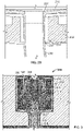
FIG. 2A is a half, side cross-sectional view of a first example torch igniter. -
FIG. 2B is an enlarged view of the portion ofFIG. 2A marked 2B-2B. -
FIG. 3 is a diagram illustrating a velocity flow field achieved by operation of a second example torch igniter. -
FIG. 4 is a half, side cross-sectional view of a third example torch igniter system. - In a gas turbine engine, the torch igniter ignites fuel released by combustor nozzles in a combustor of the engine to produce heated combustion products. The heated combustion products are, in turn, expanded through a turbine of the engine to produce torque. Reliable ignition and flame propagation around the primary combustor nozzles in conditions with relatively low air pressure drop (delta P) may require a heightened minimum level of ignition energy provided to the operating envelope. This concern is often exacerbated when the ambient environment is particularly cold. In order to provide sufficient ignition energy across a broad range of operating conditions in different ambient environments, high-quality flame stability/operability of the torch igniter system is desired.
- In certain aspects, the present disclosure relates to torch igniter systems that supply high ignition energy by incorporating various combinations of design features in the igniter body. In some implementations, for example, the igniter body includes an auxiliary combustion chamber with a premixing cup that directs a mixture of fuel and air into a recirculation zone proximate an ignition source. The entrance to the premixing cup may include an air swirler to enhance recirculation and mixing of the auxiliary air and fuel flows in the auxiliary combustion chamber.
- In some implementations, optimization of the turbulence and swirling components is achieved to sustain the torch igniter flame without having to keep the ignition source on. In some implementations, a torch igniter in accordance with one or more embodiments of the present disclosure can improve cold day combustor light off performance, and provide reliable re-light capability across a wide range of operating conditions by providing high energy release that is enhanced by swirl stabilized combustion in the torch combustor.
- Further, certain torch igniter systems of the present disclosure incorporate design features that extend the operational life of components having high-temperature failure mechanisms. For instance, in some implementations, a side wall of the auxiliary combustion chamber includes a pattern of distributed cooling apertures. As discussed in detail below, the cooling apertures can be configured to enable cooling fluid (e.g., air) to contact the inner surface of the auxiliary combustion chamber without adversely affecting the combustion conditions therein (e.g., fuel/air ratio, air/fuel temperatures, air/fuel flow velocities, etc.). As another example, in some implementations, an outlet tube receiving the combustion products from the auxiliary combustion chamber includes a pattern of dilution apertures. The dilution apertures on the outlet tube can be configured to facilitate mixing of a dilution fluid (e.g., air) with the combustion products to effect a temperature change.
-
FIG. 1 is a half, side cross-sectional view of an examplegas turbine engine 10. Thegas turbine engine 10 is turbojet-type gas turbine that could be used, for example, to power jet aircrafts. However, it is appreciated that the concepts described in the present disclosure are not so limited, and can be incorporated in the design of various other types of gas turbine engines (e.g., turbofan, turboprop, turboshaft, or industrial/marine engines). - As shown, the
gas turbine engine 10 generally facilitates a continuous axial flow of gas. That is, gas generally flows through theengine 10 in the axially downstream direction indicated by the arrows inFIG. 1 . Thegas turbine engine 10 includes anintake 12 that receives ambient air 14 and directs the ambient air to acompressor 16. The ambient air 14 is drawn through multiple stages of thecompressor 16. High-pressure air 18 exiting thecompressor 16 is introduced to acombustor 100. In certain instances, thecombustor 100 is an annular combustor circumscribing the engine's main shaft 20 or a can-type combustor positioned radially outward of the shaft. - The
combustor 100 includes acombustion shield 102,multiple fuel injectors 104, acombustor dome 106, and atorch igniter system 108. At thecombustor 100, the high-pressure air 18 is mixed with liquid or gaseous fuel (not shown) and ignited by thetorch igniter system 108 to produce heated combustion products 22. The combustion products 22 are passed through multiple stages of aturbine 24. Theturbine 24 extracts energy from the high-pressure, high-temperature combustion products 22. Energy extracted from the combustion products 22 by theturbine 24 drives thecompressor 16, which is coupled to the turbine by the main shaft 20.Exhaust gas 26 leaving theturbine 24 is accelerated into the atmosphere through anexhaust nozzle 28 to provide thrust or propulsion power or energy for electrical power generation. -
FIGS. 2A-2B show anexample torch igniter 200 that can be used in thetorch igniter system 108 ofFIG. 1 . In certain instances, thetorch igniter system 108 includes multiple, spaced aparttorch igniters 200. In this example, thetorch igniter 200 includes anigniter body 202, anauxiliary fuel injector 204, and anignition source 206. Theigniter body 202 includes amain housing 208 outlining a hollow, substantially cylindrical interior cavity but could be different shape based on physical envelope requirement. The interior cavity of themain housing 208 receives anauxiliary combustion chamber 210. An annular gap between the outer surface of theauxiliary combustion chamber 210 and the inner surface of thehousing 208 defines a fluid passage 212. Thefuel injector 204 andignition source 206 are supported by thehousing 208. Theignition source 206, for example, is mounted directly to thehousing 208, extending through an opening in the housing's side wall. A temperature sensor 213 (e.g., a thermocouple) is similarly mounted to thehousing 208. Theauxiliary fuel injector 204 is coupled to thehousing 208 via a mountingbracket 214. That is, the mountingbracket 214 carries thefuel injector 204 and is directly attached (bolted, in this example) to the front end of themain housing 208. - In this example, the
auxiliary fuel injector 204 includes anozzle orifice 216, afuel inlet line 218 and afuel bypass line 220. Thefuel inlet 218 is placed in fluid communication with a pressurized source of fuel (not shown). During use, pressurized fuel from the source flows toward thenozzle orifice 216 via thefuel inlet line 218. At least a portion of this fuel flow bypasses thenozzle orifice 216 and is returned to the main engine fuel manifold by thefuel bypass line 220. In some examples, the fuel injector incorporates additional design features for enhancing fuel atomization and increasing fuel turn down ratio to meet fuel flow requirement at all operating conditions without changing the size of thenozzle orifice 216, which may otherwise induce coking. - The
auxiliary combustion chamber 210 received within the interior of themain housing 208 features a cylindrical body including acurved side wall 226 extending between substantially planar front and rear end walls 228,230. The cylindrical body of theauxiliary combustion chamber 210 defines an axial length "L" and a radial diameter "D". In some examples, the volume and/or the L/D ratio of theauxiliary combustion chamber 210 may affect flame stabilization. For example, flame stabilization can be improved by providing theauxiliary combustion chamber 210 with a volume and/or an L/D ratio that reduces the reference velocity of the fluid (i.e., the theoretical flow velocity of air through an area equal to the maximum cross section of the combustor casing). Improved flame stabilization may enable thetorch igniter 200 to sustain the flame at higher pressure drop conditions, which increases the operating envelope of the primary combustor. - The
igniter body 202 further includes an end cap provided in the form of abulkhead 232 bolted to the rear end of themain housing 208. Thebulkhead 232 generally closes off the interior cavity of thehousing 208 with the exception of a central through-bore 234. As shown, thebore 234 of thebulkhead 232 receives anoutlet tube 236 extending from afluid outlet 237 at therear end wall 230 of theauxiliary combustion chamber 210. Theoutlet tube 236 conveys heated fluid from theauxiliary combustion chamber 210 to the primary combustor. Notably, the inner diameter of the bulkhead'sbore 234 is slightly larger than the outer diameter of theoutlet tube 236, such that a narrow annular gap providing afluid inlet 238 is formed therebetween (seeFIG. 2B ). Thefluid inlet 238 is in fluid communication with the annular fluid passage 212 between thehousing 208 andauxiliary combustion chamber 210. This configuration places thefluid inlet 238 andfluid outlet 237 of theigniter body 202 in a coaxial arrangement. Thus, a single opening in the outer shell (themain housing 208 and bulkhead 232) of theigniter body 202 is used to route fluid both to and from theauxiliary combustion chamber 210. The design of thebulkhead 232 is modular and application specific. This coaxial design effectively simplifies the manufacturing and assembly process, provides a compact form factor, and also facilitates crossflow between the two fluid flows. As explained in detail below in connection withFIG. 4 , the cross flowing fluid enables incoming auxiliary air flow to be used for cooling and/or dilution purposes. - According to the invention, a
premixing cup 240 resides within the interior of theauxiliary combustion chamber 210 proximate the chamber's planarfront end wall 228. Thepremixing cup 240 includes anair inlet 242 and acylindrical wall 244. Theair inlet 242 radially surrounds theauxiliary fuel injector 204. Thecylindrical wall 244 circumscribes theair inlet 242, and therefore also surrounds thefuel injector 204 radially. Anair swirler 246 is positioned within theair inlet 242. In this example, theair swirler 246 has a disk-shaped body including a plurality of swirl openings arranged in a circumferential pattern. The swirl openings radially surround the outlet of theauxiliary fuel injector 204 and are oriented generally axially, at a canted, non-zero angle relative to the longitudinal axis of theauxiliary combustion chamber 210. Thus, the swirl openings are arranged to form a flow vortex along the longitudinal axis of theauxiliary combustion chamber 210.U.S. Patent Publication No. 2016/0047318 , the entirety of which is incorporated herein by reference, describes an axial air swirler suitable for use in conjunction with embodiments of the present disclosure. - The
cylindrical wall 244 of thepremixing cup 240 protrudes axially outward relative to thefront end wall 228 of theauxiliary combustion chamber 210 to extend through a frontal portion of the auxiliary combustion chamber's interior cavity. Thecylindrical wall 244 delineates two discrete zones within the frontal portion in the auxiliary combustion chamber 210 - apremixing zone 248 that is radially inward of the cylindrical wall and arecirculation zone 250 that is radially outward of the cylindrical wall. Thepremixing zone 248 provides a compact area for introducing the auxiliary flow of air to atomized fuel from thefuel injector 204, which enhances the degree of fuel/air mixing. When the mixed flow of air and fuel is expelled from thepremixing cup 440 it immediately enters a downstream portion of theauxiliary combustion chamber 210. The empty space in therecirculation zone 250 draws a portion of the fuel/air mixture backwards in the auxiliary combustion chamber towards the chamber'sfront wall 228, creating a turbulent, toroidal flow pattern (seeFig. 3 ). This recirculating flow sustains combustion without having to maintain theignition source 206 in an "on" condition, because a portion of the ignited air/fuel flow is recirculated back into the incoming fuel flow from thepremixing zone 248. Even further, the turbulence and recirculation tends to mix the combusting air/fuel with uncombusted air/fuel, which more evenly ignites the air/fuel mixture throughout theauxiliary combustion chamber 210. This produces stronger, higher energy combustion. - The diagram of
FIG. 3 illustrates how fluid flows through atorch ignitor 300, which is similar in construction to thetorch igniter 200 ofFIGS. 2A and2B . As shown inFIG. 3 , an auxiliary flow of air enters anigniter body 302 of thetorch igniter 300 via afluid inlet 338. The auxiliary air flows from thefluid inlet 338 into anannular fluid passage 312. Thefluid passage 312 directs the auxiliary airflow towards the air inlet of apremixing cup 340 where it is introduced to anaxial air swirler 346. The auxiliary air traverses theair swirler 346 and flows into amixing zone 348 defined by acylindrical wall 344 of thepremixing cup 340. In themixing zone 348, the swirling auxiliary airflow meets and mixes with atomized fuel discharged from the auxiliary fuel injector 314. The fuel/air mixture flows from the mixingzone 348 into the remaining area of the auxiliary combustion chamber's interior cavity, including arecirculation zone 350 radially separated from thepremixing zone 348 by thecylindrical wall 344. The fuel/air mixture is energized (e.g., ignited) by the ignition source, which is positioned in theauxiliary combustion chamber 310 proximate therecirculation zone 350. Heated fluid then flows through theauxiliary combustion chamber 310 towards thefluid outlet 337 and into the outlet tube 336, which leads to the primary combustion chamber. -
FIG. 4 shows anotherexample torch igniter 400. Like the previous examples,torch igniter 400 includes anigniter body 402, anauxiliary fuel injector 404, and anignition source 406. Theigniter body 402 includes amain housing 408 and abulkhead 432 enclosing a hollow interior cavity containing anauxiliary combustion chamber 410. Thebulkhead 432 includes acentral bore 434 that receives anoutlet tube 436 leading from theauxiliary combustion chamber 410. The respective annular gaps between the auxiliary combustion chamber 420 and thebulkhead 432 andmain housing 408 define afluid inlet 438 leading to afluid passage 412. The interior of theauxiliary combustion chamber 410 includes apremixing cup 440 having an air inlet 442 receiving an air swirler 446. Thepremixing cup 440 further includes an axially protrudingcylindrical wall 444 delineating a frontal portion of the auxiliary combustion chamber into amixing zone 448 and arecirculation zone 450. - In this example, the
auxiliary fuel injector 404 incorporates additional design features and control scheme for enhancing fuel atomization and increasing fuel turn down ratio to meet fuel flow requirement at all operating conditions without changing the size of the nozzle orifice, which may otherwise induce coking. - In this example, the
curved side wall 426 of theauxiliary combustion chamber 410 includes a distributed pattern of coolingapertures 452. The coolingapertures 452 project through theside wall 426 of theauxiliary combustion chamber 410, enabling a portion of the auxiliary air flow traversing theannular fluid passage 412 to enter theauxiliary combustion chamber 410. In this example, each of the coolingapertures 452 is obliquely canted relative to the inner surface of the chamber'scurved side wall 426. The angled orientation of the coolingapertures 452 causes air entering theauxiliary combustion chamber 410 therethrough to form a fluid film along the chamber's inner surface. The film of auxiliary air adheres to the inner surface of theauxiliary combustion chamber 410, and therefore is inhibited from comingling with the air/fuel mixture flowing from thepremixing cup 440. This allows the auxiliary airflow to cool theauxiliary combustion chamber 410 without affecting the stoichiometry of the combustion process. The distribution of cooling apertures may vary between different implementations. For example, different implementations may employ more or less cooling apertures without departing from the scope of the present disclosure. Moreover, in some implementations, the distribution of cooling apertures may vary across the length of the auxiliary combustion chamber. For instance, in this example, the density of cooling apertures increases from the front end of theauxiliary combustion chamber 410 towards the rear end. - In addition to the cooling
apertures 452,torch igniter 400 further includes a plurality ofdilution apertures 454. In this example, thedilution apertures 454 are located along theoutlet tube 436 that conveys heated fluid from theauxiliary combustion chamber 410 to the primary combustor. The dilution apertures 454 are configured to divert a portion of the auxiliary air flow from theannular fluid inlet 438. Unlike the coolingapertures 452, thedilution apertures 454 are designed to direct the incoming air into the flowpath of heated fluid exiting the auxiliary combustion chamber through theoutlet tube 436. For example, thedilution apertures 454 may be substantially perpendicular to the curved surface of theoutlet tube 436, as opposed to obliquely canted. The auxiliary air flow mixes with the heated fluid and dilutes the composition, which results in a relatively swift drop in temperature. - While the embodiment of
FIG. 4 provides cooling apertures along the auxiliary combustion chamber and dilution apertures along the outlet tube, various other configurations are also contemplated within the scope of the present disclosure. Indeed, either or both of the auxiliary combustion chamber and outlet tube may include cooling and/or dilution apertures in different implementations. - The
torch igniter 400 still further includes ashielding device 456 residing within the interior cavity of theauxiliary combustion chamber 410. Theshielding device 456 is designed to at least partially shield theignition source 406 from direct contact with the air/fuel mixture flowing from thepremixing cup 440. In this example, theshielding device 456 includes curved body having a convex outer surface facing thepremixing cup 440. As shown, theshielding device 456 further includes multiple apertures 458 distributed along the body that permit a limited portion of the fuel/air mixture to flow passed the tip of theignition source 406. In some implementations, shielding theignition source 406 in this way inhibits quenching that tends to occur at relatively cold fuel and air conditions and/or high pressure drop conditions.
Claims (15)
- A gas turbine combustor assembly (10), comprising:a primary combustion chamber in fluid communication with a primary fuel injector (104) and a primary air inlet; anda torch ignitor (108) coupled to the primary combustion chamber, the torch igniter comprising:an auxiliary fuel injector (204);an ignition source (206); andan igniter body (202) carrying the auxiliary fuel injector and the ignition source, the igniter body comprising:an auxiliary combustion chamber (210) having a side wall extending axially from a first end wall to a second end wall, the side wall defining an interior cavity between the first and second end walls; anda premixing cup (240) residing within the interior cavity comprising a cylindrical wall (244) radially surrounding the auxiliary fuel injector and an auxiliary air inlet (242), the cylindrical wall of the premixing cup protruding axially outward relative to the first end wall of the auxiliary combustion chamber through a portion of the interior cavity to delineate a premixing zone (248) radially inward of the cylindrical wall and a recirculation zone (250) radially outward of the cylindrical wall, with the ignition source residing on the side wall of the auxiliary combustion chamber at a position proximate the recirculation zone.
- The combustor assembly of claim 1, wherein the torch igniter further comprises:
an auxiliary fuel source in fluid communication with a nozzle orifice (216) of the auxiliary fuel injector, the auxiliary fuel source configured to provide a pressurized flow of fuel for injection into the auxiliary combustion chamber by the auxiliary fuel injector; and a bypass line (220) configured to return at least a portion of the pressurized flow of fuel to a main engine fuel manifold. - The combustor assembly of claim 1 or claim 2, wherein the auxiliary combustion chamber is substantially cylindrical in shape, with the side wall having a circular cross-section of constant diameter, and the first and second end walls being substantially planar.
- The combustor assembly of any one of claims 1-3, wherein the second end wall defines a fluid outlet (237) leading to an outlet tube (236) in fluid communication with the primary combustion chamber; and
wherein the igniter body further comprises an outer shell surrounding at least a portion of the auxiliary combustion chamber, the outer shell comprising a fluid inlet (238) coaxially aligned with the outlet tube, and optionally wherein the igniter body comprises a fluid annulus formed between an inner surface of the shell and an outer surface of the auxiliary combustion chamber, the annulus directing fluid from the fluid inlet across the outer surface of the auxiliary combustion chamber towards the first end wall. - The combustor assembly of any one of claims 1-4, wherein the second end wall of the auxiliary combustion chamber defines a fluid outlet (237) leading to an outlet tube (236) in fluid communication with the primary combustion chamber, at least a portion of the outlet tube comprising a distributed pattern of dilution apertures (454), with each of the dilution apertures configured to direct fluid in cross-flow with heated gas exiting the auxiliary combustion chamber through the outlet tube.
- The combustor assembly of any one of claims 1-5, wherein the igniter body further comprises a fluid swirler (246) residing at an entrance to the premixing cup, and optionally wherein the fluid swirler comprises an axial fluid swirler (346) comprising a circumferential pattern of swirl opening surrounding an outlet of the auxiliary fuel injector.
- The combustor assembly of any one of claims 1-6, wherein the torch igniter further comprises a shielding device (456) configured to at least partially shield the ignition source from fluid flow through the auxiliary combustion chamber, and optionally wherein the shielding device is coupled to an inner surface of the auxiliary combustion chamber proximate the ignition source, and comprises a curved, convex surface projecting towards the premixing cup.
- The combustor assembly of any one of claims 1-7, wherein at least a portion of the side wall of the auxiliary combustion chamber comprises a distributed pattern of cooling apertures (452), with each of the cooling apertures obliquely canted relative to an inner surface of the side wall so as to cause fluid entering an interior cavity of the auxiliary combustion chamber through the cooling apertures to form a fluid film along the inner surface.
- A method of operating a gas turbine combustor assembly (10) according to claim 1, the method comprising:receiving auxiliary flows of fuel and air in a premixing cup (240) of an igniter body (202) of the gas turbine combustor assembly;at least partially mixing the auxiliary fuel and air flows in a premixing zone (248) of the premixing cup, and discharging the auxiliary fuel/air mixture into an auxiliary combustion chamber (210) of the igniter body;directing the discharged auxiliary fuel/air mixture into a primary recirculation zone (250) comprising an annular space between the premixing cup and an inner surface of the auxiliary combustion chamber;igniting the auxiliary fuel/air mixture at a location proximate the primary recirculation zone to form an auxiliary flow of heated fluid; andigniting a primary air/fuel mixture in a primary combustion chamber of the gas turbine combustor assembly with the auxiliary flow of heated fluid from the auxiliary combustion chamber of the igniter body.
- The method of claim 9, wherein receiving the auxiliary flow of fuel comprises directing a pressurized flow of fuel from an auxiliary fuel source to a nozzle orifice (216) of an auxiliary fuel injector in fluid communication with the premixing cup, bypassing the nozzle orifice with at least a portion of the fuel flow, and directing the bypassed portion of the fuel flow to a main engine fuel manifold.
- The method of claim 9 or claim 10, wherein receiving the auxiliary flow of air comprises directing the air through a fluid inlet (238), and wherein the method further comprises:
directing the auxiliary flow of heated fluid through a fluid outlet tube (236) coaxially aligned with the fluid inlet as the auxiliary flow of air is directed through the fluid inlet. - The method of any one of claims 9-11, further comprising:
diluting the auxiliary flow of heated fluid by directing a portion of the auxiliary flow of air in cross-flow with the auxiliary flow of heated flow through a pattern of dilution apertures (454) of the outlet tube. - The method of any one of claims 9-12, further comprising:
cooling a portion of the auxiliary combustion chamber by forming a cooling fluid film along an inner surface of the auxiliary combustion chamber, and optionally wherein forming the cooling fluid film comprises directing a portion of the auxiliary flow of air through a distributed pattern of obliquely canted cooling apertures (452) of the auxiliary combustion chamber. - The method of any one of claims 9-13, wherein at least partially mixing the auxiliary fuel and air flows comprises inducing a swirling flow pattern in each of the flows.
- The method of any one of claims 9-14, wherein igniting the auxiliary fuel/air mixture comprises energizing an ignition source (206) while at least partially shielding the ignition source from the auxiliary fuel/air mixture.
Applications Claiming Priority (2)
| Application Number | Priority Date | Filing Date | Title |
|---|---|---|---|
| US15/643,736 US10704469B2 (en) | 2017-07-07 | 2017-07-07 | Auxiliary Torch Ingnition |
| PCT/US2018/040003 WO2019010056A1 (en) | 2017-07-07 | 2018-06-28 | Auxiliary torch ignition |
Publications (2)
| Publication Number | Publication Date |
|---|---|
| EP3649404A1 EP3649404A1 (en) | 2020-05-13 |
| EP3649404B1 true EP3649404B1 (en) | 2022-12-14 |
Family
ID=62981349
Family Applications (1)
| Application Number | Title | Priority Date | Filing Date |
|---|---|---|---|
| EP18743654.8A Active EP3649404B1 (en) | 2017-07-07 | 2018-06-28 | Auxiliary torch ignition |
Country Status (4)
| Country | Link |
|---|---|
| US (1) | US10704469B2 (en) |
| EP (1) | EP3649404B1 (en) |
| CN (1) | CN111033126B (en) |
| WO (1) | WO2019010056A1 (en) |
Families Citing this family (27)
| Publication number | Priority date | Publication date | Assignee | Title |
|---|---|---|---|---|
| US10711699B2 (en) | 2017-07-07 | 2020-07-14 | Woodward, Inc. | Auxiliary torch ignition |
| US11519334B2 (en) * | 2017-07-31 | 2022-12-06 | General Electric Company | Torch igniter for a combustor |
| US10815893B2 (en) * | 2018-01-04 | 2020-10-27 | Woodward, Inc. | Combustor assembly with primary and auxiliary injector fuel control |
| US11421601B2 (en) | 2019-03-28 | 2022-08-23 | Woodward, Inc. | Second stage combustion for igniter |
| US20210396182A1 (en) * | 2020-06-23 | 2021-12-23 | Woodward, Inc. | Ignition system for power generation engine |
| US11326521B2 (en) | 2020-06-30 | 2022-05-10 | General Electric Company | Methods of igniting liquid fuel in a turbomachine |
| US11608783B2 (en) | 2020-11-04 | 2023-03-21 | Delavan, Inc. | Surface igniter cooling system |
| US11692488B2 (en) | 2020-11-04 | 2023-07-04 | Delavan Inc. | Torch igniter cooling system |
| US11473505B2 (en) | 2020-11-04 | 2022-10-18 | Delavan Inc. | Torch igniter cooling system |
| US11635027B2 (en) | 2020-11-18 | 2023-04-25 | Collins Engine Nozzles, Inc. | Fuel systems for torch ignition devices |
| US11421602B2 (en) | 2020-12-16 | 2022-08-23 | Delavan Inc. | Continuous ignition device exhaust manifold |
| US11226103B1 (en) | 2020-12-16 | 2022-01-18 | Delavan Inc. | High-pressure continuous ignition device |
| US11486309B2 (en) * | 2020-12-17 | 2022-11-01 | Delavan Inc. | Axially oriented internally mounted continuous ignition device: removable hot surface igniter |
| US11754289B2 (en) | 2020-12-17 | 2023-09-12 | Delavan, Inc. | Axially oriented internally mounted continuous ignition device: removable nozzle |
| US11635210B2 (en) | 2020-12-17 | 2023-04-25 | Collins Engine Nozzles, Inc. | Conformal and flexible woven heat shields for gas turbine engine components |
| US11286862B1 (en) | 2020-12-18 | 2022-03-29 | Delavan Inc. | Torch injector systems for gas turbine combustors |
| US11209164B1 (en) | 2020-12-18 | 2021-12-28 | Delavan Inc. | Fuel injector systems for torch igniters |
| US11680528B2 (en) * | 2020-12-18 | 2023-06-20 | Delavan Inc. | Internally-mounted torch igniters with removable igniter heads |
| US11566565B2 (en) | 2020-12-23 | 2023-01-31 | Collins Engine Nozzles, Inc. | Access hatch for internally mounted torch ignitor |
| US11415059B2 (en) * | 2020-12-23 | 2022-08-16 | Collins Engine Nozzles, Inc. | Tangentially mounted torch ignitors |
| US11415058B2 (en) * | 2020-12-23 | 2022-08-16 | Collins Engine Nozzles, Inc. | Torch ignitors with tangential injection |
| US11708793B2 (en) | 2020-12-23 | 2023-07-25 | Collins Engine Nozzles, Inc. | Torch ignitors with gas assist start |
| US11543130B1 (en) | 2021-06-28 | 2023-01-03 | Collins Engine Nozzles, Inc. | Passive secondary air assist nozzles |
| US11674445B2 (en) | 2021-08-30 | 2023-06-13 | Collins Engine Nozzles, Inc. | Cooling for continuous ignition devices |
| US11674446B2 (en) | 2021-08-30 | 2023-06-13 | Collins Engine Nozzles, Inc. | Cooling for surface ignitors in torch ignition devices |
| US11549441B1 (en) | 2021-10-12 | 2023-01-10 | Collins Engine Nozzles, Inc. | Fuel injectors with torch ignitors |
| US11773784B2 (en) | 2021-10-12 | 2023-10-03 | Collins Engine Nozzles, Inc. | Fuel injectors with torch ignitors |
Family Cites Families (30)
| Publication number | Priority date | Publication date | Assignee | Title |
|---|---|---|---|---|
| GB618688A (en) | 1946-09-16 | 1949-02-25 | David Havelock Ballantyne | Improvements in or relating to fuel-supply systems for gas-turbines |
| US2760340A (en) * | 1954-08-30 | 1956-08-28 | Clifford E Seglem | Igniter and combustion apparatus |
| GB799898A (en) * | 1955-03-28 | 1958-08-13 | Snecma | Improvements in ignition devices, especially applicable to combustion chambers of engines and propulsion units |
| US2967224A (en) * | 1956-10-08 | 1961-01-03 | Ford Motor Co | Hot wire igniter |
| DE1096684B (en) | 1958-09-09 | 1961-01-05 | Entwicklungsbau Pirna Veb | Ignition device for gas turbine engines |
| US3297914A (en) | 1964-05-28 | 1967-01-10 | United Aircraft Canada | Glow plug igniters |
| US3954389A (en) * | 1974-12-19 | 1976-05-04 | United Technologies Corporation | Torch igniter |
| US4141213A (en) | 1977-06-23 | 1979-02-27 | General Motors Corporation | Pilot flame tube |
| JPS598652B2 (en) | 1978-03-01 | 1984-02-25 | トヨタ自動車株式会社 | torch igniter |
| JPS5833232Y2 (en) * | 1978-06-27 | 1983-07-25 | 日産自動車株式会社 | Gas turbine torch igniter |
| DE2839280A1 (en) * | 1978-09-09 | 1980-03-20 | Bosch Gmbh Robert | Oil gasifying burner with starting flame stabiliser - has perforated mixing tube holding air velocity below flame propagation velocity |
| US4301656A (en) | 1979-09-28 | 1981-11-24 | General Motors Corporation | Lean prechamber outflow combustor with continuous pilot flow |
| DE3241730A1 (en) * | 1982-11-11 | 1984-05-17 | Deutsche Forschungs- und Versuchsanstalt für Luft- und Raumfahrt e.V., 5300 Bonn | GASIFICATION OIL BURNER WITH AN OIL SPRAYING DEVICE |
| DE120174T1 (en) * | 1983-02-28 | 1985-03-28 | United Technologies Corp., Hartford, Conn. | COMBUSTION CHAMBER. |
| US4860533A (en) | 1987-09-17 | 1989-08-29 | Prutech Ii | Torch igniter for a combustor having U.V. flame detection |
| GB8724455D0 (en) | 1987-10-19 | 1987-11-25 | Secr Defence | Torch igniter for combustion chambers |
| US4923371A (en) * | 1988-04-01 | 1990-05-08 | General Electric Company | Wall having cooling passage |
| US5515681A (en) | 1993-05-26 | 1996-05-14 | Simmonds Precision Engine Systems | Commonly housed electrostatic fuel atomizer and igniter apparatus for combustors |
| US6748735B2 (en) | 2002-08-13 | 2004-06-15 | The Boeing Company | Torch igniter |
| US7299620B2 (en) | 2004-06-29 | 2007-11-27 | Peter Stuttaford | Tornado torch igniter |
| US8161725B2 (en) | 2008-09-22 | 2012-04-24 | Pratt & Whitney Rocketdyne, Inc. | Compact cyclone combustion torch igniter |
| US8726631B2 (en) | 2009-11-23 | 2014-05-20 | Honeywell International Inc. | Dual walled combustors with impingement cooled igniters |
| US8844260B2 (en) * | 2010-11-09 | 2014-09-30 | Opra Technologies B.V. | Low calorific fuel combustor for gas turbine |
| EP2685161B1 (en) * | 2012-07-10 | 2018-01-17 | Ansaldo Energia Switzerland AG | Combustor arrangement, especially for a gas turbine |
| AU2013300488B2 (en) | 2012-08-07 | 2015-04-23 | Hino Motors, Ltd. | Burner |
| US9212823B2 (en) * | 2012-09-06 | 2015-12-15 | General Electric Company | Systems and methods for suppressing combustion driven pressure fluctuations with a premix combustor having multiple premix times |
| US9599343B2 (en) | 2012-11-28 | 2017-03-21 | General Electric Company | Fuel nozzle for use in a turbine engine and method of assembly |
| US9080772B2 (en) * | 2013-06-13 | 2015-07-14 | Delavan Inc | Continuous ignition |
| US10584639B2 (en) * | 2014-08-18 | 2020-03-10 | Woodward, Inc. | Torch igniter |
| GB201418042D0 (en) | 2014-10-13 | 2014-11-26 | Rolls Royce Plc | A liner element for a combustor, and a related method |
-
2017
- 2017-07-07 US US15/643,736 patent/US10704469B2/en active Active
-
2018
- 2018-06-28 CN CN201880058182.4A patent/CN111033126B/en active Active
- 2018-06-28 EP EP18743654.8A patent/EP3649404B1/en active Active
- 2018-06-28 WO PCT/US2018/040003 patent/WO2019010056A1/en unknown
Also Published As
| Publication number | Publication date |
|---|---|
| US10704469B2 (en) | 2020-07-07 |
| CN111033126A (en) | 2020-04-17 |
| CN111033126B (en) | 2022-01-28 |
| US20190010872A1 (en) | 2019-01-10 |
| EP3649404A1 (en) | 2020-05-13 |
| WO2019010056A1 (en) | 2019-01-10 |
Similar Documents
| Publication | Publication Date | Title |
|---|---|---|
| EP3649404B1 (en) | Auxiliary torch ignition | |
| EP3649403B1 (en) | Auxiliary torch ignition | |
| EP3438541B1 (en) | Gas turbine with combustor and igniter | |
| EP1323982B1 (en) | Fuel nozzle for a gas turbine engine | |
| CN106796031B (en) | Torch type igniter | |
| EP1499800B1 (en) | Fuel premixing module for gas turbine engine combustor | |
| US4271674A (en) | Premix combustor assembly | |
| US5836163A (en) | Liquid pilot fuel injection method and apparatus for a gas turbine engine dual fuel injector | |
| US8365531B2 (en) | Fuel injector | |
| US6374615B1 (en) | Low cost, low emissions natural gas combustor | |
| US8011188B2 (en) | Augmentor with trapped vortex cavity pilot | |
| US4429527A (en) | Turbine engine with combustor premix system | |
| EP0893650B1 (en) | Multi-swirler carburetor | |
| US5826423A (en) | Dual fuel injection method and apparatus with multiple air blast liquid fuel atomizers | |
| EP1058063B1 (en) | Liquid fuel injector for burners in gas turbines | |
| EP1186832A2 (en) | Fuel nozzle assembly for reduced exhaust emissions | |
| CN106461219B (en) | Burner arrangement for a combustion device | |
| CN107270328B (en) | Closed trapped vortex cavity pilot for gas turbine engine amplifier | |
| JP2012154618A (en) | Mixer assembly for gas turbine engine | |
| US5267442A (en) | Fuel nozzle with eccentric primary circuit orifice | |
| CA2845458A1 (en) | Slinger combustor | |
| US5782079A (en) | Miniature liquid-fueled turbojet engine | |
| US20060292504A1 (en) | After-burner chamber with secure ignition | |
| US5088287A (en) | Combustor for a turbine | |
| CN114258473B (en) | Combustion chamber comprising an auxiliary injection system and fuel supply method |
Legal Events
| Date | Code | Title | Description |
|---|---|---|---|
| STAA | Information on the status of an ep patent application or granted ep patent |
Free format text: STATUS: UNKNOWN |
|
| STAA | Information on the status of an ep patent application or granted ep patent |
Free format text: STATUS: THE INTERNATIONAL PUBLICATION HAS BEEN MADE |
|
| PUAI | Public reference made under article 153(3) epc to a published international application that has entered the european phase |
Free format text: ORIGINAL CODE: 0009012 |
|
| STAA | Information on the status of an ep patent application or granted ep patent |
Free format text: STATUS: REQUEST FOR EXAMINATION WAS MADE |
|
| 17P | Request for examination filed |
Effective date: 20200114 |
|
| AK | Designated contracting states |
Kind code of ref document: A1 Designated state(s): AL AT BE BG CH CY CZ DE DK EE ES FI FR GB GR HR HU IE IS IT LI LT LU LV MC MK MT NL NO PL PT RO RS SE SI SK SM TR |
|
| AX | Request for extension of the european patent |
Extension state: BA ME |
|
| DAV | Request for validation of the european patent (deleted) | ||
| DAX | Request for extension of the european patent (deleted) | ||
| GRAP | Despatch of communication of intention to grant a patent |
Free format text: ORIGINAL CODE: EPIDOSNIGR1 |
|
| STAA | Information on the status of an ep patent application or granted ep patent |
Free format text: STATUS: GRANT OF PATENT IS INTENDED |
|
| INTG | Intention to grant announced |
Effective date: 20220802 |
|
| GRAS | Grant fee paid |
Free format text: ORIGINAL CODE: EPIDOSNIGR3 |
|
| GRAA | (expected) grant |
Free format text: ORIGINAL CODE: 0009210 |
|
| STAA | Information on the status of an ep patent application or granted ep patent |
Free format text: STATUS: THE PATENT HAS BEEN GRANTED |
|
| AK | Designated contracting states |
Kind code of ref document: B1 Designated state(s): AL AT BE BG CH CY CZ DE DK EE ES FI FR GB GR HR HU IE IS IT LI LT LU LV MC MK MT NL NO PL PT RO RS SE SI SK SM TR |
|
| REG | Reference to a national code |
Ref country code: GB Ref legal event code: FG4D |
|
| REG | Reference to a national code |
Ref country code: CH Ref legal event code: EP |
|
| REG | Reference to a national code |
Ref country code: DE Ref legal event code: R096 Ref document number: 602018044252 Country of ref document: DE |
|
| REG | Reference to a national code |
Ref country code: IE Ref legal event code: FG4D |
|
| REG | Reference to a national code |
Ref country code: AT Ref legal event code: REF Ref document number: 1537886 Country of ref document: AT Kind code of ref document: T Effective date: 20230115 |
|
| REG | Reference to a national code |
Ref country code: LT Ref legal event code: MG9D |
|
| REG | Reference to a national code |
Ref country code: NL Ref legal event code: MP Effective date: 20221214 |
|
| PG25 | Lapsed in a contracting state [announced via postgrant information from national office to epo] |
Ref country code: SE Free format text: LAPSE BECAUSE OF FAILURE TO SUBMIT A TRANSLATION OF THE DESCRIPTION OR TO PAY THE FEE WITHIN THE PRESCRIBED TIME-LIMIT Effective date: 20221214 Ref country code: NO Free format text: LAPSE BECAUSE OF FAILURE TO SUBMIT A TRANSLATION OF THE DESCRIPTION OR TO PAY THE FEE WITHIN THE PRESCRIBED TIME-LIMIT Effective date: 20230314 Ref country code: LT Free format text: LAPSE BECAUSE OF FAILURE TO SUBMIT A TRANSLATION OF THE DESCRIPTION OR TO PAY THE FEE WITHIN THE PRESCRIBED TIME-LIMIT Effective date: 20221214 Ref country code: FI Free format text: LAPSE BECAUSE OF FAILURE TO SUBMIT A TRANSLATION OF THE DESCRIPTION OR TO PAY THE FEE WITHIN THE PRESCRIBED TIME-LIMIT Effective date: 20221214 |
|
| REG | Reference to a national code |
Ref country code: AT Ref legal event code: MK05 Ref document number: 1537886 Country of ref document: AT Kind code of ref document: T Effective date: 20221214 |
|
| PG25 | Lapsed in a contracting state [announced via postgrant information from national office to epo] |
Ref country code: RS Free format text: LAPSE BECAUSE OF FAILURE TO SUBMIT A TRANSLATION OF THE DESCRIPTION OR TO PAY THE FEE WITHIN THE PRESCRIBED TIME-LIMIT Effective date: 20221214 Ref country code: LV Free format text: LAPSE BECAUSE OF FAILURE TO SUBMIT A TRANSLATION OF THE DESCRIPTION OR TO PAY THE FEE WITHIN THE PRESCRIBED TIME-LIMIT Effective date: 20221214 Ref country code: HR Free format text: LAPSE BECAUSE OF FAILURE TO SUBMIT A TRANSLATION OF THE DESCRIPTION OR TO PAY THE FEE WITHIN THE PRESCRIBED TIME-LIMIT Effective date: 20221214 Ref country code: GR Free format text: LAPSE BECAUSE OF FAILURE TO SUBMIT A TRANSLATION OF THE DESCRIPTION OR TO PAY THE FEE WITHIN THE PRESCRIBED TIME-LIMIT Effective date: 20230315 |
|
| PG25 | Lapsed in a contracting state [announced via postgrant information from national office to epo] |
Ref country code: NL Free format text: LAPSE BECAUSE OF FAILURE TO SUBMIT A TRANSLATION OF THE DESCRIPTION OR TO PAY THE FEE WITHIN THE PRESCRIBED TIME-LIMIT Effective date: 20221214 |
|
| P01 | Opt-out of the competence of the unified patent court (upc) registered |
Effective date: 20230619 |
|
| PG25 | Lapsed in a contracting state [announced via postgrant information from national office to epo] |
Ref country code: SM Free format text: LAPSE BECAUSE OF FAILURE TO SUBMIT A TRANSLATION OF THE DESCRIPTION OR TO PAY THE FEE WITHIN THE PRESCRIBED TIME-LIMIT Effective date: 20221214 Ref country code: RO Free format text: LAPSE BECAUSE OF FAILURE TO SUBMIT A TRANSLATION OF THE DESCRIPTION OR TO PAY THE FEE WITHIN THE PRESCRIBED TIME-LIMIT Effective date: 20221214 Ref country code: PT Free format text: LAPSE BECAUSE OF FAILURE TO SUBMIT A TRANSLATION OF THE DESCRIPTION OR TO PAY THE FEE WITHIN THE PRESCRIBED TIME-LIMIT Effective date: 20230414 Ref country code: ES Free format text: LAPSE BECAUSE OF FAILURE TO SUBMIT A TRANSLATION OF THE DESCRIPTION OR TO PAY THE FEE WITHIN THE PRESCRIBED TIME-LIMIT Effective date: 20221214 Ref country code: EE Free format text: LAPSE BECAUSE OF FAILURE TO SUBMIT A TRANSLATION OF THE DESCRIPTION OR TO PAY THE FEE WITHIN THE PRESCRIBED TIME-LIMIT Effective date: 20221214 Ref country code: CZ Free format text: LAPSE BECAUSE OF FAILURE TO SUBMIT A TRANSLATION OF THE DESCRIPTION OR TO PAY THE FEE WITHIN THE PRESCRIBED TIME-LIMIT Effective date: 20221214 Ref country code: AT Free format text: LAPSE BECAUSE OF FAILURE TO SUBMIT A TRANSLATION OF THE DESCRIPTION OR TO PAY THE FEE WITHIN THE PRESCRIBED TIME-LIMIT Effective date: 20221214 |
|
| PGFP | Annual fee paid to national office [announced via postgrant information from national office to epo] |
Ref country code: FR Payment date: 20230626 Year of fee payment: 6 Ref country code: DE Payment date: 20230626 Year of fee payment: 6 |
|
| PG25 | Lapsed in a contracting state [announced via postgrant information from national office to epo] |
Ref country code: SK Free format text: LAPSE BECAUSE OF FAILURE TO SUBMIT A TRANSLATION OF THE DESCRIPTION OR TO PAY THE FEE WITHIN THE PRESCRIBED TIME-LIMIT Effective date: 20221214 Ref country code: PL Free format text: LAPSE BECAUSE OF FAILURE TO SUBMIT A TRANSLATION OF THE DESCRIPTION OR TO PAY THE FEE WITHIN THE PRESCRIBED TIME-LIMIT Effective date: 20221214 Ref country code: IS Free format text: LAPSE BECAUSE OF FAILURE TO SUBMIT A TRANSLATION OF THE DESCRIPTION OR TO PAY THE FEE WITHIN THE PRESCRIBED TIME-LIMIT Effective date: 20230414 Ref country code: AL Free format text: LAPSE BECAUSE OF FAILURE TO SUBMIT A TRANSLATION OF THE DESCRIPTION OR TO PAY THE FEE WITHIN THE PRESCRIBED TIME-LIMIT Effective date: 20221214 |
|
| REG | Reference to a national code |
Ref country code: DE Ref legal event code: R097 Ref document number: 602018044252 Country of ref document: DE |
|
| PLBE | No opposition filed within time limit |
Free format text: ORIGINAL CODE: 0009261 |
|
| STAA | Information on the status of an ep patent application or granted ep patent |
Free format text: STATUS: NO OPPOSITION FILED WITHIN TIME LIMIT |
|
| PG25 | Lapsed in a contracting state [announced via postgrant information from national office to epo] |
Ref country code: DK Free format text: LAPSE BECAUSE OF FAILURE TO SUBMIT A TRANSLATION OF THE DESCRIPTION OR TO PAY THE FEE WITHIN THE PRESCRIBED TIME-LIMIT Effective date: 20221214 |
|
| PGFP | Annual fee paid to national office [announced via postgrant information from national office to epo] |
Ref country code: GB Payment date: 20230627 Year of fee payment: 6 |
|
| 26N | No opposition filed |
Effective date: 20230915 |
|
| PG25 | Lapsed in a contracting state [announced via postgrant information from national office to epo] |
Ref country code: SI Free format text: LAPSE BECAUSE OF FAILURE TO SUBMIT A TRANSLATION OF THE DESCRIPTION OR TO PAY THE FEE WITHIN THE PRESCRIBED TIME-LIMIT Effective date: 20221214 |
|
| PG25 | Lapsed in a contracting state [announced via postgrant information from national office to epo] |
Ref country code: MC Free format text: LAPSE BECAUSE OF FAILURE TO SUBMIT A TRANSLATION OF THE DESCRIPTION OR TO PAY THE FEE WITHIN THE PRESCRIBED TIME-LIMIT Effective date: 20221214 |
|
| PG25 | Lapsed in a contracting state [announced via postgrant information from national office to epo] |
Ref country code: MC Free format text: LAPSE BECAUSE OF FAILURE TO SUBMIT A TRANSLATION OF THE DESCRIPTION OR TO PAY THE FEE WITHIN THE PRESCRIBED TIME-LIMIT Effective date: 20221214 |
|
| REG | Reference to a national code |
Ref country code: CH Ref legal event code: PL |
|
| REG | Reference to a national code |
Ref country code: BE Ref legal event code: MM Effective date: 20230630 |
|
| PG25 | Lapsed in a contracting state [announced via postgrant information from national office to epo] |
Ref country code: LU Free format text: LAPSE BECAUSE OF NON-PAYMENT OF DUE FEES Effective date: 20230628 |
|
| REG | Reference to a national code |
Ref country code: IE Ref legal event code: MM4A |
|
| PG25 | Lapsed in a contracting state [announced via postgrant information from national office to epo] |
Ref country code: LU Free format text: LAPSE BECAUSE OF NON-PAYMENT OF DUE FEES Effective date: 20230628 |