EP3648703B1 - Dental scanner with ultrasonic sensor component for augmentation of optical data - Google Patents
Dental scanner with ultrasonic sensor component for augmentation of optical data Download PDFInfo
- Publication number
- EP3648703B1 EP3648703B1 EP18759184.7A EP18759184A EP3648703B1 EP 3648703 B1 EP3648703 B1 EP 3648703B1 EP 18759184 A EP18759184 A EP 18759184A EP 3648703 B1 EP3648703 B1 EP 3648703B1
- Authority
- EP
- European Patent Office
- Prior art keywords
- probe
- optionally
- ios
- sensor
- dental scanner
- Prior art date
- Legal status (The legal status is an assumption and is not a legal conclusion. Google has not performed a legal analysis and makes no representation as to the accuracy of the status listed.)
- Active
Links
- 230000003287 optical effect Effects 0.000 title claims description 19
- 230000003416 augmentation Effects 0.000 title description 4
- 239000000523 sample Substances 0.000 claims description 499
- 238000005259 measurement Methods 0.000 claims description 60
- 239000000463 material Substances 0.000 claims description 27
- 238000002604 ultrasonography Methods 0.000 claims description 17
- 238000003384 imaging method Methods 0.000 claims description 15
- 238000012014 optical coherence tomography Methods 0.000 claims description 5
- 210000000515 tooth Anatomy 0.000 description 130
- 239000007943 implant Substances 0.000 description 73
- 210000000988 bone and bone Anatomy 0.000 description 54
- 238000000034 method Methods 0.000 description 35
- 210000000214 mouth Anatomy 0.000 description 30
- 210000001519 tissue Anatomy 0.000 description 28
- 210000003128 head Anatomy 0.000 description 27
- 210000004195 gingiva Anatomy 0.000 description 22
- 230000003239 periodontal effect Effects 0.000 description 22
- 239000000835 fiber Substances 0.000 description 20
- 239000004053 dental implant Substances 0.000 description 17
- 208000005888 Periodontal Pocket Diseases 0.000 description 16
- 230000000670 limiting effect Effects 0.000 description 15
- 238000013507 mapping Methods 0.000 description 15
- 239000013307 optical fiber Substances 0.000 description 15
- 239000012530 fluid Substances 0.000 description 12
- 210000004877 mucosa Anatomy 0.000 description 12
- 238000010586 diagram Methods 0.000 description 11
- 210000004872 soft tissue Anatomy 0.000 description 11
- 238000000605 extraction Methods 0.000 description 10
- 229910052751 metal Inorganic materials 0.000 description 10
- 239000002184 metal Substances 0.000 description 10
- 230000000740 bleeding effect Effects 0.000 description 9
- 239000008280 blood Substances 0.000 description 9
- 210000004369 blood Anatomy 0.000 description 9
- 238000005299 abrasion Methods 0.000 description 7
- 230000006870 function Effects 0.000 description 7
- 238000004519 manufacturing process Methods 0.000 description 7
- 238000001356 surgical procedure Methods 0.000 description 7
- 230000000694 effects Effects 0.000 description 6
- 230000036541 health Effects 0.000 description 6
- 238000003780 insertion Methods 0.000 description 6
- 230000037431 insertion Effects 0.000 description 6
- 230000002829 reductive effect Effects 0.000 description 6
- 238000012546 transfer Methods 0.000 description 6
- 206010061218 Inflammation Diseases 0.000 description 5
- 238000005452 bending Methods 0.000 description 5
- 230000001427 coherent effect Effects 0.000 description 5
- 210000003298 dental enamel Anatomy 0.000 description 5
- 238000001514 detection method Methods 0.000 description 5
- 238000005286 illumination Methods 0.000 description 5
- 230000004054 inflammatory process Effects 0.000 description 5
- 239000003550 marker Substances 0.000 description 5
- 230000007246 mechanism Effects 0.000 description 5
- 238000002360 preparation method Methods 0.000 description 5
- 238000002679 ablation Methods 0.000 description 4
- 210000003484 anatomy Anatomy 0.000 description 4
- 230000003042 antagnostic effect Effects 0.000 description 4
- 230000008878 coupling Effects 0.000 description 4
- 238000010168 coupling process Methods 0.000 description 4
- 238000005859 coupling reaction Methods 0.000 description 4
- 238000005520 cutting process Methods 0.000 description 4
- 238000002513 implantation Methods 0.000 description 4
- 230000008569 process Effects 0.000 description 4
- 238000005096 rolling process Methods 0.000 description 4
- 208000002697 Tooth Abrasion Diseases 0.000 description 3
- 239000004568 cement Substances 0.000 description 3
- 230000006378 damage Effects 0.000 description 3
- 238000005553 drilling Methods 0.000 description 3
- 238000003801 milling Methods 0.000 description 3
- 239000002245 particle Substances 0.000 description 3
- 238000007639 printing Methods 0.000 description 3
- 238000004080 punching Methods 0.000 description 3
- XLYOFNOQVPJJNP-UHFFFAOYSA-N water Substances O XLYOFNOQVPJJNP-UHFFFAOYSA-N 0.000 description 3
- 238000010146 3D printing Methods 0.000 description 2
- 208000033809 Suppuration Diseases 0.000 description 2
- 230000003190 augmentative effect Effects 0.000 description 2
- 230000015271 coagulation Effects 0.000 description 2
- 238000005345 coagulation Methods 0.000 description 2
- 238000004891 communication Methods 0.000 description 2
- 238000002591 computed tomography Methods 0.000 description 2
- 230000003750 conditioning effect Effects 0.000 description 2
- 230000037123 dental health Effects 0.000 description 2
- 238000013461 design Methods 0.000 description 2
- 230000002439 hemostatic effect Effects 0.000 description 2
- 239000007788 liquid Substances 0.000 description 2
- 210000005036 nerve Anatomy 0.000 description 2
- 230000035515 penetration Effects 0.000 description 2
- 239000004033 plastic Substances 0.000 description 2
- 238000005498 polishing Methods 0.000 description 2
- 238000002310 reflectometry Methods 0.000 description 2
- 238000005507 spraying Methods 0.000 description 2
- 238000012360 testing method Methods 0.000 description 2
- 206010053567 Coagulopathies Diseases 0.000 description 1
- 229910000684 Cobalt-chrome Inorganic materials 0.000 description 1
- 229920001875 Ebonite Polymers 0.000 description 1
- 239000004677 Nylon Substances 0.000 description 1
- 229910000831 Steel Inorganic materials 0.000 description 1
- 239000004809 Teflon Substances 0.000 description 1
- 229920006362 Teflon® Polymers 0.000 description 1
- RTAQQCXQSZGOHL-UHFFFAOYSA-N Titanium Chemical compound [Ti] RTAQQCXQSZGOHL-UHFFFAOYSA-N 0.000 description 1
- 230000005856 abnormality Effects 0.000 description 1
- 239000003082 abrasive agent Substances 0.000 description 1
- 239000000654 additive Substances 0.000 description 1
- 230000000996 additive effect Effects 0.000 description 1
- 239000000853 adhesive Substances 0.000 description 1
- 230000001070 adhesive effect Effects 0.000 description 1
- 230000003444 anaesthetic effect Effects 0.000 description 1
- 230000002744 anti-aggregatory effect Effects 0.000 description 1
- 230000000844 anti-bacterial effect Effects 0.000 description 1
- 239000003146 anticoagulant agent Substances 0.000 description 1
- 238000000149 argon plasma sintering Methods 0.000 description 1
- 230000036770 blood supply Effects 0.000 description 1
- 238000004364 calculation method Methods 0.000 description 1
- 230000005465 channeling Effects 0.000 description 1
- 238000004140 cleaning Methods 0.000 description 1
- 230000035602 clotting Effects 0.000 description 1
- 239000010952 cobalt-chrome Substances 0.000 description 1
- 150000001875 compounds Chemical class 0.000 description 1
- 230000001010 compromised effect Effects 0.000 description 1
- 230000002596 correlated effect Effects 0.000 description 1
- 230000000875 corresponding effect Effects 0.000 description 1
- 238000009826 distribution Methods 0.000 description 1
- 239000003814 drug Substances 0.000 description 1
- 229940079593 drug Drugs 0.000 description 1
- 239000012636 effector Substances 0.000 description 1
- 230000008030 elimination Effects 0.000 description 1
- 238000003379 elimination reaction Methods 0.000 description 1
- 238000005516 engineering process Methods 0.000 description 1
- 230000003628 erosive effect Effects 0.000 description 1
- 238000011156 evaluation Methods 0.000 description 1
- 230000005284 excitation Effects 0.000 description 1
- 230000001815 facial effect Effects 0.000 description 1
- 239000000945 filler Substances 0.000 description 1
- 201000005562 gingival recession Diseases 0.000 description 1
- 238000000227 grinding Methods 0.000 description 1
- 238000011065 in-situ storage Methods 0.000 description 1
- 208000015181 infectious disease Diseases 0.000 description 1
- 238000007726 management method Methods 0.000 description 1
- 238000000691 measurement method Methods 0.000 description 1
- 210000002200 mouth mucosa Anatomy 0.000 description 1
- 210000000944 nerve tissue Anatomy 0.000 description 1
- 229920001778 nylon Polymers 0.000 description 1
- 230000007170 pathology Effects 0.000 description 1
- 230000000704 physical effect Effects 0.000 description 1
- 239000004417 polycarbonate Substances 0.000 description 1
- 229920000515 polycarbonate Polymers 0.000 description 1
- 238000012545 processing Methods 0.000 description 1
- 238000011084 recovery Methods 0.000 description 1
- 230000003595 spectral effect Effects 0.000 description 1
- 239000010935 stainless steel Substances 0.000 description 1
- 229910001220 stainless steel Inorganic materials 0.000 description 1
- 230000003068 static effect Effects 0.000 description 1
- 239000010959 steel Substances 0.000 description 1
- 230000001954 sterilising effect Effects 0.000 description 1
- 239000000126 substance Substances 0.000 description 1
- 230000008961 swelling Effects 0.000 description 1
- 230000001225 therapeutic effect Effects 0.000 description 1
- 238000009210 therapy by ultrasound Methods 0.000 description 1
- 239000010936 titanium Substances 0.000 description 1
- 229910052719 titanium Inorganic materials 0.000 description 1
- 238000012549 training Methods 0.000 description 1
- 230000032258 transport Effects 0.000 description 1
Images


Classifications
-
- A—HUMAN NECESSITIES
- A61—MEDICAL OR VETERINARY SCIENCE; HYGIENE
- A61C—DENTISTRY; APPARATUS OR METHODS FOR ORAL OR DENTAL HYGIENE
- A61C17/00—Devices for cleaning, polishing, rinsing or drying teeth, teeth cavities or prostheses; Saliva removers; Dental appliances for receiving spittle
- A61C17/16—Power-driven cleaning or polishing devices
- A61C17/20—Power-driven cleaning or polishing devices using ultrasonics
-
- A—HUMAN NECESSITIES
- A61—MEDICAL OR VETERINARY SCIENCE; HYGIENE
- A61B—DIAGNOSIS; SURGERY; IDENTIFICATION
- A61B1/00—Instruments for performing medical examinations of the interior of cavities or tubes of the body by visual or photographical inspection, e.g. endoscopes; Illuminating arrangements therefor
- A61B1/00163—Optical arrangements
- A61B1/00193—Optical arrangements adapted for stereoscopic vision
-
- A—HUMAN NECESSITIES
- A61—MEDICAL OR VETERINARY SCIENCE; HYGIENE
- A61B—DIAGNOSIS; SURGERY; IDENTIFICATION
- A61B1/00—Instruments for performing medical examinations of the interior of cavities or tubes of the body by visual or photographical inspection, e.g. endoscopes; Illuminating arrangements therefor
- A61B1/24—Instruments for performing medical examinations of the interior of cavities or tubes of the body by visual or photographical inspection, e.g. endoscopes; Illuminating arrangements therefor for the mouth, i.e. stomatoscopes, e.g. with tongue depressors; Instruments for opening or keeping open the mouth
-
- A—HUMAN NECESSITIES
- A61—MEDICAL OR VETERINARY SCIENCE; HYGIENE
- A61B—DIAGNOSIS; SURGERY; IDENTIFICATION
- A61B5/00—Measuring for diagnostic purposes; Identification of persons
- A61B5/0059—Measuring for diagnostic purposes; Identification of persons using light, e.g. diagnosis by transillumination, diascopy, fluorescence
- A61B5/0062—Arrangements for scanning
- A61B5/0066—Optical coherence imaging
-
- A—HUMAN NECESSITIES
- A61—MEDICAL OR VETERINARY SCIENCE; HYGIENE
- A61B—DIAGNOSIS; SURGERY; IDENTIFICATION
- A61B5/00—Measuring for diagnostic purposes; Identification of persons
- A61B5/0059—Measuring for diagnostic purposes; Identification of persons using light, e.g. diagnosis by transillumination, diascopy, fluorescence
- A61B5/0082—Measuring for diagnostic purposes; Identification of persons using light, e.g. diagnosis by transillumination, diascopy, fluorescence adapted for particular medical purposes
- A61B5/0088—Measuring for diagnostic purposes; Identification of persons using light, e.g. diagnosis by transillumination, diascopy, fluorescence adapted for particular medical purposes for oral or dental tissue
-
- A—HUMAN NECESSITIES
- A61—MEDICAL OR VETERINARY SCIENCE; HYGIENE
- A61B—DIAGNOSIS; SURGERY; IDENTIFICATION
- A61B5/00—Measuring for diagnostic purposes; Identification of persons
- A61B5/45—For evaluating or diagnosing the musculoskeletal system or teeth
- A61B5/4538—Evaluating a particular part of the muscoloskeletal system or a particular medical condition
- A61B5/4542—Evaluating the mouth, e.g. the jaw
- A61B5/4547—Evaluating teeth
-
- A—HUMAN NECESSITIES
- A61—MEDICAL OR VETERINARY SCIENCE; HYGIENE
- A61B—DIAGNOSIS; SURGERY; IDENTIFICATION
- A61B8/00—Diagnosis using ultrasonic, sonic or infrasonic waves
- A61B8/12—Diagnosis using ultrasonic, sonic or infrasonic waves in body cavities or body tracts, e.g. by using catheters
-
- A—HUMAN NECESSITIES
- A61—MEDICAL OR VETERINARY SCIENCE; HYGIENE
- A61B—DIAGNOSIS; SURGERY; IDENTIFICATION
- A61B8/00—Diagnosis using ultrasonic, sonic or infrasonic waves
- A61B8/44—Constructional features of the ultrasonic, sonic or infrasonic diagnostic device
- A61B8/4483—Constructional features of the ultrasonic, sonic or infrasonic diagnostic device characterised by features of the ultrasound transducer
- A61B8/4488—Constructional features of the ultrasonic, sonic or infrasonic diagnostic device characterised by features of the ultrasound transducer the transducer being a phased array
-
- A—HUMAN NECESSITIES
- A61—MEDICAL OR VETERINARY SCIENCE; HYGIENE
- A61B—DIAGNOSIS; SURGERY; IDENTIFICATION
- A61B8/00—Diagnosis using ultrasonic, sonic or infrasonic waves
- A61B8/44—Constructional features of the ultrasonic, sonic or infrasonic diagnostic device
- A61B8/4483—Constructional features of the ultrasonic, sonic or infrasonic diagnostic device characterised by features of the ultrasound transducer
- A61B8/4494—Constructional features of the ultrasonic, sonic or infrasonic diagnostic device characterised by features of the ultrasound transducer characterised by the arrangement of the transducer elements
-
- A—HUMAN NECESSITIES
- A61—MEDICAL OR VETERINARY SCIENCE; HYGIENE
- A61C—DENTISTRY; APPARATUS OR METHODS FOR ORAL OR DENTAL HYGIENE
- A61C17/00—Devices for cleaning, polishing, rinsing or drying teeth, teeth cavities or prostheses; Saliva removers; Dental appliances for receiving spittle
- A61C17/02—Rinsing or air-blowing devices, e.g. using fluid jets or comprising liquid medication
- A61C17/0202—Hand-pieces
-
- A—HUMAN NECESSITIES
- A61—MEDICAL OR VETERINARY SCIENCE; HYGIENE
- A61C—DENTISTRY; APPARATUS OR METHODS FOR ORAL OR DENTAL HYGIENE
- A61C17/00—Devices for cleaning, polishing, rinsing or drying teeth, teeth cavities or prostheses; Saliva removers; Dental appliances for receiving spittle
- A61C17/02—Rinsing or air-blowing devices, e.g. using fluid jets or comprising liquid medication
- A61C17/022—Air-blowing devices, e.g. with means for heating the air
-
- A—HUMAN NECESSITIES
- A61—MEDICAL OR VETERINARY SCIENCE; HYGIENE
- A61C—DENTISTRY; APPARATUS OR METHODS FOR ORAL OR DENTAL HYGIENE
- A61C19/00—Dental auxiliary appliances
- A61C19/04—Measuring instruments specially adapted for dentistry
- A61C19/043—Depth measuring of periodontal pockets; Probes therefor
-
- A—HUMAN NECESSITIES
- A61—MEDICAL OR VETERINARY SCIENCE; HYGIENE
- A61C—DENTISTRY; APPARATUS OR METHODS FOR ORAL OR DENTAL HYGIENE
- A61C9/00—Impression cups, i.e. impression trays; Impression methods
- A61C9/004—Means or methods for taking digitized impressions
- A61C9/0046—Data acquisition means or methods
- A61C9/0053—Optical means or methods, e.g. scanning the teeth by a laser or light beam
-
- A—HUMAN NECESSITIES
- A61—MEDICAL OR VETERINARY SCIENCE; HYGIENE
- A61C—DENTISTRY; APPARATUS OR METHODS FOR ORAL OR DENTAL HYGIENE
- A61C9/00—Impression cups, i.e. impression trays; Impression methods
- A61C9/004—Means or methods for taking digitized impressions
- A61C9/0046—Data acquisition means or methods
- A61C9/008—Mechanical means or methods, e.g. a contact probe moving over the teeth
-
- B—PERFORMING OPERATIONS; TRANSPORTING
- B06—GENERATING OR TRANSMITTING MECHANICAL VIBRATIONS IN GENERAL
- B06B—METHODS OR APPARATUS FOR GENERATING OR TRANSMITTING MECHANICAL VIBRATIONS OF INFRASONIC, SONIC, OR ULTRASONIC FREQUENCY, e.g. FOR PERFORMING MECHANICAL WORK IN GENERAL
- B06B1/00—Methods or apparatus for generating mechanical vibrations of infrasonic, sonic, or ultrasonic frequency
- B06B1/02—Methods or apparatus for generating mechanical vibrations of infrasonic, sonic, or ultrasonic frequency making use of electrical energy
- B06B1/06—Methods or apparatus for generating mechanical vibrations of infrasonic, sonic, or ultrasonic frequency making use of electrical energy operating with piezoelectric effect or with electrostriction
- B06B1/0607—Methods or apparatus for generating mechanical vibrations of infrasonic, sonic, or ultrasonic frequency making use of electrical energy operating with piezoelectric effect or with electrostriction using multiple elements
Definitions
- the present invention in some embodiments thereof, relates to a dental probe, optionally provided as part of or an attachment for an intra oral scanner (IOS) and/or optionally providing imaging or sensing or other functionality.
- IOS intra oral scanner
- a device used for such measuring may include a main body comprising a final optical element of an imager which defines an optical field of view directed in a first direction; and a measurement element coupled to said main body extending generally in said first direction; where a tip of said measurement element is sized and shaped to be inserted between a tooth and adjacent gingiva; where said optical field of view is sized to image at least part of a tooth.”
- U.S. Patent Publication No. US2016/120615 which states "Devices and methods for ultrasonic dental treatment are described, wherein the devices and methods can comprise a flexible array of cooperative ultrasound transducers.
- the array can contain individual ultrasonic transducers that can perform both functions of emitting and sensing.
- the transducers can have the ability to interchange their functions from emitting to sensing.
- the transducers can cooperate in providing an ultrasound treatment and each transducer can be independently controlled by an external source controller.
- An ultrasound system is provided comprising: an ultrasound transducer sensor array operable to emit or sense ultrasound, wherein the timing and intensity of emission may be controlled by an electronic controller based on a feedback signal from the sensors.
- the ultrasound system can also have the ability to sense coupling to a treatment tissue. This ability to sense proper coupling can improve the efficacy of the treatment.”
- U.S. Patent Publication No. US2009/306506 which states "A device (10) for acquiring data in the mouth of a patient, wherein the device (10) comprises an ultrasound sensor (20) and a support structure.
- the ultrasound sensor (20) is stored by means of the support structure when not in use and contains ultrasound deflection means (12) which are movable.
- a coupling body (21) is provided, which is arranged between the ultrasound deflection means (12) and a tooth area (1, 2, 3) or remaining tooth area to be swept over Excitation signals (14) are sent to the ultrasound sensor (20) and the ultrasound deflection means (12) are moved in order to thus produce an ultrasonic wave which sweeps over at least part of the tooth area (1, 2, 3) or remaining tooth area.”
- the present invention relates to a dental scanner according to claim 1.
- An aspect of some embodiments of the invention relates to an IOS with a laterally extending probe, integral or add-on.
- the probe is within a field of view of the IOS imager.
- the probe is used to contact an intraoral surface for providing geometrical or other measurement thereof.
- a mapping by the IOS is improved by said contact.
- the probe contact is used to detect surface properties other than geometry relative to the IOS, for example, tissue stiffness.
- a probe may have an average width (e.g. diameter) ranging between 0.1 to 0.5 mm and/or between 0.5 to 1.0 mm and/or between 1 to 2 mm and/or between 2 to 4 mm.
- the probe is used to measure one or more of a tooth extraction socket, a drilled socket, a soft tissue surface, a bone surface under soft tissue, a dental implant, a tooth, space between teeth, periodontal pocket, a sub-gingival section of a tooth, a dental abrasion pattern and or a recess in a tooth.
- the measured space is measurable using the IOS, and the probe provides enhanced resolution.
- the probe is used to measure surfaces that are not measurable using the IOS, for example, due to field of view limitations thereof.
- the probe laterally extends, for example, at an angle of between 30 and 150 degrees relative to an axis of a handle of the IOS.
- the probe includes an imager, for example, an ultrasound imager (for example a side viewing ultrasonic imager (IVUS) or a Piezoelectric Micromachined Ultrasound Transducer (PMUT) array)), a sensor, for example, an ultrasound sensor or stain sensor and/or a mirror, for example, reflecting a view lateral to the probe to an imager of the IOS.
- an ultrasound imager for example a side viewing ultrasonic imager (IVUS) or a Piezoelectric Micromachined Ultrasound Transducer (PMUT) array
- PMUT Piezoelectric Micromachined Ultrasound Transducer
- the probe includes an effector, for example, a tool for tissue ablation or coagulation.
- the probe includes a channel, for example, for providing a fluid or removing fluid.
- the channel is connected to a reservoir and/or a source, for example, of cement or sterilizing fluid.
- a channel may have an average cross sectional area along the probe ranging between 0.01 mm 2 to 0.1 mm 2 and/or between 0.1 mm 2 to 0.25 mm 2 and/or between 0.25 mm 2 to 1. mm 2 and/or between 1 mm 2 to 25 mm 2 .
- the channel may take up between 1% to 10% and/or between 10% to 30% and/or between 30% to 60% and/or between 60% to 90% of the probe.
- IOS location measurement uncertainty will be reduced by between 50 to 90%.
- an IOS scanner may have a measurement error of less than 40 ⁇ m and/or a location of a feature at a probe tip may be measured with an error of less than 10 ⁇ m and/or 5 ⁇ m and/or less than 2 ⁇ m.
- One or more points of high accuracy measurements may be used to condition measurements in other locations to decrease measurement uncertainty in regions of the domain where the probe tip was not used for a direct measurement.
- the error in a region may be reduced to below 5 ⁇ m and/or below 10 ⁇ m and/or below 20 ⁇ m and/or below 30 ⁇ m.
- conditioning may be used to improve the accuracy of a depth mapped image.
- An aspect of some embodiments related to embodiments of the invention relates to measurement of intraoral surfaces using an IOS having a laterally extending probe.
- the probe tip is atraumatic.
- the IOS is used to position the probe in a 3D representation of the oral cavity or apportion thereof.
- the IOS is used to measure one or more of mucosa, artificial objects (on their own, relative to each other, orientation, and/or relative to natural tissues and/or natural objects of various types), shapes of cavities (e.g., natural, artificial or resulting from tissue extraction), implant shapes, prosthesis shapes, shapes of surfaces that mate with prostheses (e.g., for bone onlay and/or supra-contact).
- shapes of cavities e.g., natural, artificial or resulting from tissue extraction
- implant shapes e.g., prosthesis shapes, shapes of surfaces that mate with prostheses (e.g., for bone onlay and/or supra-contact).
- measurement is used to determine one or more of teeth closure, abrasion patterns, plaque, post crown inaccuracy and/or root apex depth.
- the probe tip penetrates the gums and can be used to measure gum thickness by comparing pre- and post-penetration positions.
- the probe tip is used to sense non-geometrical properties, for example, elasticity (e.g., using a strain sensor) and/or color (e.g., using an optical detector).
- the probe will be used to exert pressure on an object.
- the IOS may collect data about the movement of the object and/or tissue and/or teeth due to forces exerted by the probe.
- a probe may include a fiducial marker.
- a probe tip may include a sensor.
- the probe tip may include an imager and/or a linear measurement sensor (for example a laser range finder and/or an ultrasound range finder).
- the probe tip sensor may augment IOS measurements in areas that are difficult to measure with a conventional IOS sensor, for example, inside a recess and/or between teeth and/or in an area angled away from the sensor and/or in an obscured area.
- a same measurement tool is used both intraorally and on objects outside of the mouth, for example, a yet-to-be deployed prosthesis.
- intra-oral features are used to identify a location in a model or an image or a scan of a mouth.
- a location of a probe connected to the IOS is used to identify a location in a model or an image or a scan of a mouth relative to the IOS.
- a tip of a probe connected to the IOS is used to identify a location in a model or an image or a scan of a mouth relative to the IOS.
- the IOS includes a laterally extending probe which includes one or more longitudinal channels for passage of materials to, from and/or within the intraoral cavity and optionally having an opening at the side and/or tip of the probe.
- a laterally extending probe which includes one or more longitudinal channels for passage of materials to, from and/or within the intraoral cavity and optionally having an opening at the side and/or tip of the probe.
- materials for example, one or more of water, abrasive materials, adhesive materials, and/or filler materials may be provided via such a channel.
- the channel is connected to a suction source for material removal.
- such a channel includes an optical fiber for providing therapeutic and/or imaging light.
- an aspect of some embodiments of the invention relates to an IOS having a laterally extending probe which supports side viewing.
- the probe includes a mirror which reflects light towards an IOS imager component.
- the probe includes one or more optical or ultrasonic sensor or imager.
- the imager is a 3D imager and/or software for reconstructing a 3D image form moving imagers is provided at a control station.
- a sensor may include an optical coherence tomography OCT system, for example to image areas below the surface of tissue.
- a probe may be used in evaluation and/or treatment of periodontal conditions.
- a probe may be used to measure periodontal pocket depths.
- a probe with a sensor may be used to measure a periodontal condition.
- the probe and/or the sensor may be inserted into a periodontal pocket.
- the sensor may sense color.
- a sensor may be used to identify a cemental enamel junction and/or bleeding and/or inflammation.
- a probe may include a source of ultraviolet light and/or measure fluorescence, for example, to measure subgingival plaque.
- Fig. 1A is a block diagram showing of an IOS including a laterally extending probe, in accordance with some embodiments of the invention.
- the probe includes an IOS imager 106 mounted on a head 104 of the device.
- head 104 may be mounted on a handle 102.
- a laterally extending probe 108 is attached to head 104.
- the tip of probe 108 is in the field of view (FOV) of imager 106 (for example in Fig. 1B a probe 108' is shown in a FOV 116 of an imager 106').
- FOV field of view
- the 3D position of the tip of probe 108 with respect to imager may be known to a high accuracy.
- the tip of probe 108 may include a fiducial marker.
- markings on probe 108 and/or a size of the tip may be used in estimating location and/or distance to an object and/or size of the object.
- the size and/or position of the tip of probe 108 may be known with an error of less than 5 ⁇ m.
- a probe may be made of stainless steel and/or another metal and/or plastic.
- the tip of the probe may be sharp.
- the tip may be rounded and/or blunt and/or include a widening.
- the widening may have width between 1 to 5 mm and/or between 5 to 10 mm and/or between 10 to 20 mm and/or between 20 to 30 mm.
- an IOS may include a handle.
- the handle may be easily griped for example having a width of between 0.5 cm to 5 cm.
- head 104 is sized for movement inside a mouth, for example a human mouth.
- the head has dimensions between 0.5 to 3 cm.
- a user may manipulate handle 102 to scan the mouth with head 104 and/or probe 108.
- imager 106 has a high enough resolution to produce depth mapped images and/or an STL file mapping 3D features of an oral cavity with an error of less than 30 ⁇ m and/or less than 100 ⁇ m and/or less than 10 ⁇ m.
- imager 106 includes a light source.
- the light source may include a structured light and/or a coherent light.
- probe 108 is used to increase the accuracy of an IOS image and/or a STL mapping made from the image.
- having probe 108 on a scanner may save time of a dentist by facilitating producing an IOS scan while the dentist probes, checks and/or treats dental conditions.
- the IOS will produce a hard record of the procedure.
- the record may be used for evaluating and/or training of dentists.
- the record may be useful to as evidence in cases of malpractice and/or for evaluating the efficacy of interventions and/or improvements therein.
- the record may be used to evaluate progress of a procedure and/or condition and/or plan follow up.
- probe 108 may have functions that improve imaging, for example of difficult to sight surfaces (for example smooth and/or low reflectivity surfaces and/or surfaces that are obscured and/or located in a position which is difficult to reach at a good imaging pose).
- Fig. 1B is a schematic diagram showing of an IOS including a laterally extending probe 108', in accordance with some embodiments of the invention.
- a handle 102' and a head 104' may have a long axis 103.
- probe 108' is straight.
- a probe may be curved.
- probe 108' is mounted perpendicular to axis 103.
- probe 108' is mounted at an angle between 45 to 135 degrees to axis 103.
- an IOS scanner may include a mount 210 for attaching a probe attachment 208.
- mount 210 may include a snap in mount and/or a screw in mount and/or a protrusion and/or a locking switch and/or a locking pin and/or a tightening element (for example a screw).
- an IOS with a detachable probe 208 may include a calibration procedure to determine the position and/or size of the tip of probe 208.
- probe 208 may be part of a exchangeable set of tools that may serve different functions and/or may have different shapes and/or sizes for example for patients having larger and/or smaller mouths and/or whose teeth are looser and/or tighter.
- the IOS may be used with probe 208 unattached for conventional IOS scanning and/or with probe 208 attached for scanning and/or other functions using probe 208.
- Fig. 2B is a schematic diagram showing of an IOS having a probe attachment mountable thereon, in accordance with some exemplary embodiments related to embodiments of the invention.
- the IOS includes a threaded mount 210'.
- Mount 210' secures one of a plurality of different probes for example a straight probe 208' and/or a bent probe 208".
- thread 225 of the probe 208', 208" may connect to the mount 201'
- a probe 208', of a first shape may be used for one part of the mouth while a probe 208" of a second shape may be used for a different part of the mouth.
- a straight probe 208 may be used for the facial side of front teeth while an angled probe ', 208" may be used for the lingual side.
- changing the probe will allow use of the IOS with the probe to scan an entire mouth.
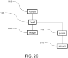
- Fig. 2C is a block diagram showing of an IOS having a probe 108 with a sensor 212 thereon, in accordance with some exemplary embodiments of the invention.
- a probe mounted sensor 212 may be used to image and/or measure a region that is not accessible to the IOS sensor 106.
- a probe mounted sensor 212 may be used to monitor progress of an intervention.
- a probe mounted sensor 212 includes an imager and/or a range finder.
- an imager may include an ultrasound imager an optical imager (for example a monochrome imager and/or a multi-color imager and/or an ultraviolet UV imager and/or an infrared IR imager and/or an OCT imager).
- a probe mounted imager may be used along with imager 106 of the IOS to make a stereoscopic and/or 3D image of an object (for example the two imagers may have overlapping fields of view).
- a range finder may include a laser range finder and/or an ultrasonic range finder.
- a probe mounted sensor 212 may include a force sensor.
- force on a probe 108 may be measured by a pressure sensor for example near the probe 108 tip.
- force on a probe may be measured by a strain sensor for example on a shank of probe 108.
- a force sensor may be located at the joint between the probe and head 104.
- pressure on a probe may be estimated by measuring deformation (e.g. elastic bending) of the probe. For example, deformation may be evaluated from images produced by the IOS.
- a force sensor may be used to evaluate the stiffness of a structure (for example a tooth and/or a bone) and/or the softness of a structure (for example gums and/or mucosa). For example, softness may be evaluated by correlating deformation of the tissue with the force applied.
- Fig. 2D is a block diagram showing of an IOS having a lateral probe 108 including a channel 214, in accordance with some exemplary embodiments of the invention.
- a channel 214 is hollow and/or connected to a reservoir 213.
- fluid in reservoir 213 may be to introduce into a zone being mapped by the IOS and/or explored with probe 108.
- a drug may be introduced to treat a condition and/or reduce pain.
- a cleaning fluid for example water
- an abrasive compound may be introduced through channel 214, for example for polishing and/or grinding oral features.
- channel 214 may be used to suction fluid out from a zone being mapped by the IOS and/or explored with probe 108.
- channel 214 include an optical fiber for introducing light into and/or viewing a zone and/or a zone being mapped by the IOS and/or explored with probe 108.
- channel 214 may include an optical fiber.
- the optical fiber may be used for channeling light to a sensor and/or an imager.
- a tool may pass through channel 214.
- wires and/or a tissue ablator may be passed through channel 214 to affect tissue in an oral cavity.
- an optical fiber may be used to pass a laser signal for tissue ablation and/or cutting oral features.
- FIG. 2E is a block diagram illustration of an IOS having a lateral probe 108 and an affector 215.
- an affector 215 may include an ablator.
- a power source 217 supplies energy to affector 215.
- power source 217 and/or affector 215 may be controlled by a controller for example including a processor.
- Figs. 3A-3E are schematic illustrations of IOS including a laterally extending imaging or sensing probes, in accordance with some embodiments of the invention.
- FIG. 3A is a schematic illustration of a probe 308 including an imager 312a in accordance with an embodiment of the current invention.
- a field of view 316b of sensor 312a of probe 308 overlaps with a field of view 316a of imager 306 of the IOS.
- imager 312a will face laterally away from a side of probe 308.
- imager 312a is used to image difficult to reach locations.
- imager 312a may improve accuracy of an imaging of a surface angled away from the IOS imager 306, for example a side view of a steep wall of tooth 309.
- the probe may be moved for scanning a structure with imager 312a, for example as illustrated arrow 318.
- imager 312a may be used to view subgingival features.
- measured features may include inflammation, and/or calculus (for example the location and extent and/or thickness) and/or plaque.
- the tip of the probe and/or sensor 312b may be inserted into a periodontal pocket to make a measurement.
- a sensor may be directed along the axis of probe 308.
- FIG. 3B is a schematic illustration of a probe 308 including a narrow FOV sensor 312b in accordance with an embodiment of the current invention.
- a sensor 312b is used to measure a feature in a field of view 316a of imager 306 of the IOS.
- sensor 312b will face laterally away from a side of probe 308.
- sensor 312b is used to measure features in difficult to reach locations.
- the probe may be moved for scanning a structure with sensor 312b, for example as illustrated arrow 318.
- sensor 312b may be used to detect and/or identify and/or measure subgingival inflammation, and/or calculus and/or plaque.
- sensor 312b may include a range finder and/or a color measuring sensor and/or a reflectivity measuring sensor.
- IOS sensor 306 may be used to map the location and/or extent of the feature. For example, the location of plaque and/or calculus may be entered into a 3D model of the mouth.
- FIG. 3C is a schematic illustration of an IOS including probe having a plurality of sensors in accordance with an embodiment of the present invention.
- probe 308 is shown with three sensors 312c, 312c' and 312c" having fields of view 316b, 316b' and 316b" respectively.
- the fields of view 316b, 316b' and 316b" overlap; for example, as overlapping fields of view 316b, 316b' and 316b".
- overlapping fields of view 316b, 316b' and 316b" may facilitate stereoscopic and/or 3D imaging.
- multiple fields of view 316b, 316b' and 316b" may facilitate imaging a large surface of a tooth 309.
- sensors 312c, 312c' and 312c" may include sensors with a narrow FOV 316c, 316c' and 316c".
- FOV's 316c, 316c' and 316c" may not overlap.
- one or more of the sensors 312c, 312c' and/or 312c" may be replaced by an illuminator.
- an illuminator may illuminate a narrow field of illumination, for example a zone having a width of greater than 2 mm.
- an illuminator may illuminate a wide field of illumination, for example a zone having a width of less than 2 mm.
- an illuminator may include a light emitting diode (LED) and/or a laser.
- LED light emitting diode
- sensors 312c, 312c' and/or 312c" may be used for 3D scanning.
- overlapping scanners may be used for stereoscopic imaging.
- a combination of scanners and illuminators may be used to produce a 3D image.
- probe 308 may include a laser line scanner.
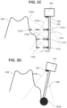
- FIGs. 3D , 3E and 3F are schematic illustrations of alternative embodiments of a scanner including a pressure sensor.
- a probe may include a pressure sensor at a distal portion thereof (for example sensor 322a as illustrated in FIG. 3D ).
- a stress sensor may be provided at the base of a probe 308 (for example sensor 322c as illustrated in FIG. 3F ).
- a strain sensor may be including in probe 308 (for example sensor 322b as illustrated in FIG. 3E ).
- pressure may be estimated based on the image produced by sensor 306 of the IOS head 304.
- the pressure on a flexible and/or elastic probe 308 may be estimated based on the location of contact of the probe 308 and an object and/or the distortion of the probe 308.
- an elastic probe may be calibrated to know how much lateral force is required at the tip of the probe to bend the probe to a particular angle. For example, from the direction and location of the point of contact between the elastic probe and an object and from the bending of the probe, the force between the probe and the object can be computed.
- Figs. 4A-4C are schematic showings of an IOS including a laterally extending probe having a reflector in a field of view 316a of the IOS, in accordance with some embodiments of the invention.
- a reflector may include a mirror.
- a reflector may by straight, and/or curved (for example concave and/or convex).
- a reflector may give IOS sensor 106 a wider view and/or a view at an additional angle and/or a view at an additional view point than the unmodified view 316a of sensor 306.
- the mirror may be used to get a side view of a tooth 309 and/or another structure (for example to see inside a recess for example a cavity in a tooth or gums).
- a mirror 424a may be located near a tip of probe 308.
- a portion 316d of FOV 316a of sensor 306 may be directed at mirror 424a.
- the mirror 424a may allow IOS sensor 306 see an additional FOV 416a.
- mirror 424b may be mounted on a pivot 426.
- pivot 426 may facilitate adjusting of an angle and/or FOV 416a of mirror 416a.
- pivot 426 may facilitate pivoting mirror 424a out of the way of an obstacle while positioning probe 308.
- pivot 426 may include an elastic element that allows mirror 424a to pivot out of the way and/or return to its pose.
- mirror 424a may be located within 1 mm of the tip of probe 308 and/or within 5 mm and/or within 20 mm and/or within 100 mm.
- a mirror may be directed to produce a field of view 416a approximately perpendicular to the probe and/or approximately perpendicular to the mean direction unmodified FOV of the IOS sensor 306.
- an angle 423 between the mean direction of the surface of the mirror and the a line from the base of the mirror and the IOS sensor 306 may range for example between 40 to 50 degrees and/or between 50 to 80 degrees and/or between 10 to 40 degrees.
- angle 423 may be fixed. Alternately or additionally, angle 423 may be adjustable.
- a mirror 424b may be mounted on an intermediate section of the probe 308.
- mirror 416b may be more than 100 mm from the tip of the probe.
- a probe 308 may have a widened portion at or near its tip.
- a tip of a probe may form a ball.
- a reflective surface 424c of the widened portion may be located in the FOV 316a of the IOS sensor 306.
- reflective surface 424c may be convex and/or may give an expanded FOV 416b at an angle to the unmodified FOV 316a of sensor 306.
- FIGs. 5A-5B are schematic illustrations of an IOS including a laterally extending probe having a channel therein, in accordance with some embodiments related to embodiments of the invention.
- a channel may be partially or completely filled.
- a channel may be permanently filled.
- the channel may be filled with a temporary object and/or the contents of the channel may be changed.
- a channel may include of fiber, and/or wire.
- an opening of channel may be on various locations and/or directed in various directions.
- opening 511b of channel 514b is on a distal end probe 308 as illustrated in FIG. 5B .
- opening 511b has a field of effect 530b.
- probe 308 is straight and/or field of effect 530b is directed along the long axis of probe 308.
- opening 511a of channel 514a is located on a side of the probe 308 for example illustrated in FIG. 5A .
- probe 308 is straight and/or a field of effect 530a is directed laterally with respect to the long axis of probe 308.
- a field of effect may include an area onto which a material is sprayed and/or a field of illumination of a light emitting fiber and/or a field of view of a sensor connected to an optical fiber.
- a channel in a probe may be in fluid communication with a reservoir 513 in the head of the device and/or the handle and/or outside the device.
- a channel in a probe may be in communication with a fluid source and/or an energy source outside the device
- reservoir 513 may contain a material to introduce into the mouth and/or may serve to store material removed from the mouth.
- reservoir 513 may include a channel to a source of a material to be introduced into the mouth (for example a source of high pressure fluid) and/or to a vacuum.
- the reservoir 513 may in include an energy source.
- the reservoir may include a battery and/or a signal generator and/or a connection to an external power source.
- power source may supply electrical power to an ablator.
- the channel 514a, 514b may include a wire to pass electrical current.
- a power source may include a light source (e.g. a non-coherent illumination source (e.g.
- channel 514a, 514b may include a light guide for example an optical fiber.
- energy passing along channel 514a, 514b may be used to perform ablation, coagulation, cutting etc.
- reservoir 513 may include a sensor, for example an electrical tester and/or an optical sensor.
- the IOS while a probe is being used in a procedure, the IOS is optionally used to track progress of the procedure.
- the probe may be used for scaling a tooth while the IOS is used to determine the initial extent of plaque and/or calculus.
- sensors on the probe will be used along with the IOS to improve identification of oral features and/or pathologies and/or their characteristics.
- the probe may be used to explore a region while the IOS maps the explored region and/or detects optical properties of the region.
- a probe will transfer materials into and/or out of the mouth to improve the performance of the IOS and/or of a probe mounted sensor (for example to increase light and/or visibility and/or to provide markings and/or acoustic coupling).
- a channel may be used to transfer materials into or out from a mouth of a patient.
- a fluid for example water
- a gas for example air
- Materials may be introduced at increased pressure, for example of between 0.1 to 1 atm and/or between 0.01 to 0.3 and/or between 1 atm to 5 atm and/or between 5 to 20 atm.
- the introduced material may be used to rinse the object, for example to wash away blood.
- a vacuum may be applied to a channel, for example for sucking the blood and/or other fluids/ from a mouth.
- sucking away liquid and/or spraying gas may dry teeth and/or decrease specular reflections from the tooth.
- reduced spectral reflection may improve the accuracy of 3D imaging.
- a hemostatic material may be introduced, for example to reduce bleeding.
- an anesthetic material may be introduced, for example to reduce pain.
- a hemostatic material may be introduced, for example to reduce bleeding.
- an anti-bacterial material may be introduced, for example to reduce inflammation.
- a material may be applied to teeth (for example sprayed on the teeth) through a channel to create features on the teeth and help create 3D models. For example a fluid containing particles may be sprayed onto teeth.
- the particles may be used as visible features for locating features on a tooth.
- a channel in a probe may be used for spraying or insert a material that causes gum retraction and/or a material that opens a sulcus.
- a channel may be used to transfer a material for affecting a surface; for example a milling and/or polishing solution.
- a milling solution containing particles may be sprayed onto a tooth through a channel in a probe.
- a channel may be used for a fiber and/or a wire.
- a hollow probe may include an internal fiber.
- the fiber includes an optical fiber that transports light.
- a light source may be included in reservoir 513 and/or at a proximal end of the fiber.
- the light carried by the fiber may be coherent and/or the light source may include a laser.
- the light may be non-coherent and/or the light source may include a light emitting diode.
- the fiber passing through probe 308 acts as a source of light.
- probe 308 may include holes and/or windows that project light columns for calibration and/or measuring distance.
- a fiber may carry light effective to cut tissue.
- a hollow probe may include an internal fiber used for delivering light for soft tissue management, such as cutting gums and/or stopping bleeding for example by clotting blood.
- a light transmitting fiber may be connected to a lights sensor.
- hollow probe may contain internal fiber connected to a light sensor that measures light reflected from an object towards the probe and/or the tip thereof and/or light reflected from the probe.
- changes in reflected light may be used to identify when the probe is touching an intra-oral object, for example a tooth.
- the sensor may measure changes in intensity and/or color.
- light may be measured with an optical detector on the probe, for example on or near a tip of the probe.
- a fiber and light sensor may be used as a newton-meter for contact/force measurement detected via changes in light.
- an optical fiber will be used to measure distance.
- a fiber may be connected to an optical length meter.
- one or more fibers will be open approximately perpendicular to the axis of probe 308.
- the fiber may be used to measure a distance from the side of probe 308 to an oral feature, for example a wall of a tooth.
- an optical length meter may be connected to a ribbon of fibers.
- the device may measure distance from each fiber end to an oral feature.
- a probe channel may transfer light without an optical fiber.
- the channel may include a light reflecting interior or other options to transfer light for any of the purposes described above with respect to optical fibers.
- Fig. 6 is a schematic showing of IOS including a laterally extending probe having an affector, in accordance with some embodiments of the invention.
- an affector may include electrodes 638a and/or 638b.
- electrodes 638a, 638b may be connected by a wire 636 to a power source 634 and/or a controller 635.
- controller 635 may include a processor.
- the power source 636 and/or controller may produce an electrical current (AC or DC and/or at a radio frequency).
- the affector may be used to ablate tissue and/or stop bleeding and/or measure resistance.
- a heated object may be mounted to a probe as an affector.
- an affector may transfer light to an intra-oral object.
- light may be used for ablation and/or milling.
- a tooth may be milled in preparation for a procedure such as attachment to prosthesis.
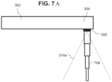
- Fig. 7A is a schematic showing of IOS including a telescopic probe, in accordance with some embodiments related to embodiments of the invention.
- a probe may be fixed and/or telescoping and/or reversibly mounted to the handle 302.
- the IOS handle 302, head 304 and/or sensor 306 may be used as a standard IOS (for example with the probe 708 and/or 208' and/or 208" collapsed and/or removed).
- the probe (for example with the probe 708 and/or 208' and/or 208") may be extended and/or attached and then used for any of the procedures and/or embodiments as described herein.
- a telescoping probe 708 may be extended automatically and/or manually.
- the telescoping probe 708 may be configured for use in a fully retracted and/or a fully extended state.
- the telescoping probe may also work in a partially extended state.
- a telescoping probe 708 includes one or more nested parts.
- the parts may retract one into the other and/or extend one from the other.
- the probe optionally extends and/or locks into an extended position.
- the parts may be connected to a linear actuator and/or interconnected by screw threads and/or another locking mechanism.
- Fig. 7B is a schematic showing a probe with a tip designed for smooth or gliding movement along an oral surface in accordance with some embodiments of the invention.
- Fig. 7B is a schematic showing an IOS 100* with a probe 718; an imager 106*; a head 104* and a handle 102*.
- the probe 718 is designed with a ball 719 at a tip 720 of the probe 718. In some embodiments the probe 718 is optionally designed so that the ball 719 can roll, optionally like a ball-point pen refill.
- the probe 718 is optionally designed with a round tip 720.
- the probe 718 is optionally designed with a tip 720 made of a smooth material, such as, by way of some non-limiting examples, Teflon, nylon.
- the ball 719 is designed to roll as it touches a scanned object, for example teeth or gums.
- the scanner includes a component to measure a rolling distance of the ball 719.
- markings such as lines or dots are drawn on the ball, and the scanner optionally images the markings, optionally with an imager, and the rolling distance is optionally calculated.
- the surface of the ball 719 optionally includes (optionally subtractive or additive) mechanical lines that are optionally sensed by a force sensor.
- the ball 719 is optionally optically clear and striped to act similarly to a computer mouse or scroll wheel encoder.
- the probe is optionally hollow, and optionally includes one or more internal optical fibers to enable viewing movement of the ball or through the ball, or collect information from the ball or through the ball.
- air pressure liquids, anti-aggregant or anti-clot material optionally keeps the ball 719 from sticking to the probe tip 720, potentially assisting the ball 719 rolling.
- Figs. 7C and 7D are schematics showing an IOS 100* with an option for release of a probe from an IOS, in accordance with some embodiments of the invention.
- Figs. 7C and 7D show a probe 108*; a probe release mechanism 723; a head 104* (in some embodiments with an optional scanner or imager, not shown) and a handle 102*, where Fig. 7C is a side view and Fig. 7D is a bottom view.
- Fig. 7D shows the example embodiment where the probe release mechanism 723is configured to release the probe 108* by inserting a tool into one or more openings 704* in the probe release mechanism 723.
- the probe release mechanism 723 is configured to release the probe 108* by inserting a tool into one or more openings 704* in the probe release mechanism 723.
- the forceps may optionally be squeezed or spread, acting via the openings 704* on a probe holder 702* to release the probe 108* from the IOS 100*.
- Figs. 7C and 7D show an option for a quick release of the probe from the IOS.
- a quick release is used in order to replace a probe 108* between patients or to replace the probe 108* type according to an anatomy of the patient, for example to replace to a shorter probe in case of shorter molar teeth, and/or to a narrower probe in case of a narrow opening between two teeth and/or to a probe with a force sensor for example to measure the force applied to a tooth.
- the quick release is optionally done with a specific tool that can create enough force to remove the probe 108* from its place.
- a tool that is already usually used by dentists can be used, for example, a tooth ring placing forceps.
- the probe holder 702* grips the probe 108* along a section long enough to provide stability against side forces shifting the probe 108* relative to an imager (not shown).
- the IOS 100* is optionally calibrated to determine the location of a probe 108* after replacement.
- Fig. 7E is an image of an optional tool for release of a probe from an IOS, in accordance with some embodiments of the invention.
- FIG. 7E shows a forceps 706* which has tips 708* which can be used for releasing a probe from an IOS, for example, referring to Fig, 7C , by inserting the tips 708* into the openings 704* as described above.
- Fig. 7F is a schematic showing a sleeve with a probe that is placed over an IOS, in accordance with some embodiments related to embodiments of the invention.
- Fig. 7F shows a probe 108* attached to a sleeve 730 and the sleeve 730 is placed over an IOS 102*.
- the sleeve 730 optionally includes a release component 732 for attaching to and detaching from the IOS 102*.
- the release component 732 is a quick release component 732.
- An enlarged portion 731 of Fig. 7F shows an optional quick release component 732.
- the sleeve 730 optionally includes a clear window or windows 733 to enable a scanner to image through the window(s) 733 in the sleeve 730.
- the sleeve 730 is made fully or partially of a light transferring material such as polycarbonate.
- the sleeve 730 can be autoclaved, in order to sterilize between uses.
- the sleeve 730 is configured so that when placed over the IOS 102* such that relative movement between the sleeve 730 and the IOS 102* is limited to less than 1 micron or 5 microns.
- the release component 732 of the sleeve 730 is configured such that relative movement between the sleeve 730 and the IOS 102* is limited to less than 1 micron or 5 microns.
- Fig. 7G is a schematic showing a probe with a tip including a ball designed for smooth movement along an oral surface in accordance with some embodiments of the invention.
- Fig. 7G is a schematic showing an IOS 100* with an imager 106* and a probe 718.
- the probe 718 of Fig. 7G is designed with a ball 719 at a tip 720 of the probe 718.
- the probe 718 is optionally designed so that the ball 719 can roll, optionally like a ball-point pen refill.
- Fig. 7G shows the ball 719 at the tip 720 of the probe 718 rolling along a surface of a tooth 722.
- Figs. 8A-8K are schematic drawings showing various dental structures which may be measured using an IOS and a probe, in accordance with some embodiments of the invention.
- FIG. 8A illustrates an IOS scanner with a probe exploring a periodontal pocket between a tooth 309 and a gum 807 in accordance with an embodiment of the current invention.
- a probe 308 may be a simple probe without an additional sensor.
- a pocket may be explored using a probe with a probe mounted sensor, for example as illustrated in FIG. 13B .
- Fig. 8B illustrates an IOS scanner including a probe measuring a recess 868 in a tooth in accordance with an embodiment of the current invention.
- a recess 868 may be scanned at high resolution in order to fit an implant.
- probe 308 is used to position a FOV 316b of probe mounted sensor to get a good view of the recess 868.
- a probe mounted sensor may inserted into the recess 868.
- a probe may be used to physically contact an internal portion of the recess 868.
- a probe physically contacting an internal portion of the recess 868 optionally includes a probe mounted sensor.
- probe physically contacting an internal portion of the recess 868 may not include a probe mounted sensor.
- FIG. 8C illustrates an IOS scanner including a probe measuring an exterior surface of a tooth in accordance with an embodiment of the present invention.
- use of the probe to measure the outer surface may improve the accuracy of a 3D map and/or STL file.
- use of a probe along with the IOS scanner may produce a high accuracy map of the surface of the tooth and/or facilitate production of an improved fitting onlay.
- mapping the surface may include touching points on the surface with the probe.
- a probe mounted sensor may be used to scan a tooth surface.
- FIG. 8D illustrates an IOS scanner including a probe measuring recess, for example a socket 870 remaining after extraction of a tooth in accordance with an embodiment of the present invention.
- a probe may improve the accuracy of a 3D map and/or STL file.
- use of a probe along with the IOS scanner may produce a high accuracy map of an inner surface of the socket and/or facilitate production of an improved fitting prosthesis, for example an inlay, an onlay and/or an implant fitting to a feature in the socket 870.
- a probe mounted sensor may be used to scan an extraction socket 870.
- the probe mounted sensor may be inserted into the socket 870.
- a probe mounted sensor may be positioned outside the socket 870 to have a FOV with good coverage of the socket 870, for example close to and/or adjacent to the opening of the socket 870.
- data from measurement of the socket 870 may be used to produce an implant for immediate and/or primary implantation.
- An IOS including a probe is optionally used to measure grooves, holes and cavities in bone, for example to be designated for medical objectives, for example, for dental implants.
- FIG. 8E illustrates a use of an IOS including a probe to measure a tooth abrasion 866 in accordance with an embodiment of the current invention.
- probe 308 is used to position a FOV 316b of a probe mounted sensor to get a good view of the abrasion 866.
- a probe may be used to physically contact the abrasion 866.
- a probe physically contacting a the abrasion 866 optionally includes a probe mounted sensor.
- a probe physically contacting abrasion 866 may not include a probe mounted sensor.
- Fig. 8F illustrates an IOS scanner including a probe measuring a region prepared for a prosthesis (for example a surface of a tooth prepared for a crown) in accordance with an embodiment of the current invention.
- a region prepared for a prosthesis for example a surface of a tooth prepared for a crown
- prepared region may be scanned at high resolution in order to fit a prosthesis.
- probe 308 is used to position a FOV 316b of probe mounted sensor to get a good view of the region.
- the probe contacts the region.
- a probe physically contacting region optionally includes a probe mounted sensor. Alternatively or additionally probe physically contacting region may not include a probe mounted sensor.
- FIG. 8G illustrates an IOS scanner including a probe measuring a prostheses after attachment in accordance with an embodiment of the present invention.
- the probe is used to measure the joint 874 between a natural structure (for example between a prepared tooth 309 and a crown 872) and the prosthesis.
- the probe may be used along with the IOS scanner to measure a height of a prosthesis and/or to measure closure of the prosthesis with an antagonistic tooth.
- a IOS scanner with a probe may measure a post insertion fit of a prosthesis without a probe mounted sensor.
- a probe measuring a post insertion fit of a prosthesis may include a probe mounted sensor.
- FIG. 8H illustrates an IOS including a probe used to measure and/or treat a calculus and/or a plaque deposit 876 in accordance with an embodiment of the current invention.
- a probe 308 may be used to contact deposit 876, for example to measure the deposit 876 and/or to scrape the deposit 876.
- the IOS will be used to map the 3D extent of the deposit 876 and/or to track progress in its removal.
- probe 308 will be a simple probe.
- the probe may measure by contact and/or remove deposit 876 by physical scaling.
- a probe may include a sensor and/or an affector (for example an ultrasonic scaler) that may take part in the measurement and/or treatment.
- FIG. 81 illustrates an IOS scanner including a probe measuring and/or treating a root of a tooth in accordance with an embodiment of the present invention.
- the probe 308 may be used to remove organic tissues and debris 863 in a root and/or the IOS may be used to measure the extent of the procedure.
- use of a probe along with the IOS scanner may produce a high accuracy map of the removed tissue and/or facilitate production of an improved fitting prosthesis, for example an inlay, an onlay and/or an implant.
- probe 308 may be a simple probe.
- the probe may include a probe mounted sensor.
- the probe may include a probe mounted affector.
- the probe may include a laser and/or a light channel to ablate the nerve 863 and/or a vacuum to remove nerve tissue and/or debris.
- the probe may be curved and/or flexible.
- FIG. 8J illustrates an IOS scanner including a probe measuring a sub-gingival structure in accordance with an embodiment of the present invention.
- a probe may be inserted through soft tissue (for example gums 807) to contact and/or measure hard tissue underneath.
- the probe 308 is optionally inserted through the gingiva of the gums 807 and optionally touches a bone in which the teeth are embedded.
- Such embodiments may be used to diagnose and for planning of periodontal surgery and/or in order to add measurement results to a periodontal chart and/or to a 3D model.
- a thickness of the gingiva tissue is optionally measured, optionally based on knowing the probe length, and knowing, optionally using the 3D scanner, where the gingiva is, and calculating the thickness of the gingiva.
- the probe 308 is made with a sharp tip, to ease insertion into a space between a tooth and gums and/or through soft tissue.
- a pressure sensor is optionally used to detect when the probe 308 contacts bone.
- FIG. 8K illustrates an IOS scanner measuring soft tissue in accordance with an embodiment of the current invention.
- a scanner may be used to measure mucosa for fitting a removable prosthesis.
- a IOS and/or probe may be used to measure a 3D form of the tissue and/or a mechanical property, for example elasticity.
- the tip 372 of the probe may optionally include an enlarged portion for improving measurement of soft tissue and/or to protect the tissue from damage.
- the probe may include a sensor, for example a force sensor.
- Fig 8L is a simplified illustration of an IOS measuring gingiva surrounding a dental implant in accordance with some embodiments of the invention.
- Fig. 8L shows gingiva 807* adjacent to an implant 808, and an IOS head 304 and probe 308.
- the IOS head 304 and the probe 308 are optionally used to collect data for producing a 3D model of the gingiva 807*, and optionally of the implant 808, and optionally of an abutment.
- the IOS head 304 and the probe 308 are optionally used to collect data for producing a 3D model of the gingiva 807* with no abutment.
- the IOS head 304 and the probe 308 are optionally used to collect data for producing a 3D model of the gingiva 807* with an abutment present.
- the 3D model is optionally used to design a custom abutment, which is optionally shaped according to the gingiva shape.
- Figs 8M and 8N are simplified illustrations of an IOS measuring parameters of a dental implant in accordance with some embodiments of the invention.
- Fig 8M and 8N show an IOS head 304 using a probe 308 measuring parameters of a dental implant 809.
- Example parameters measured by the probe 308 include, by way of some non-limiting examples, a location of the dental implant 809, orientation of the dental implant 809, shape of the dental implant, and similar geometric parameters, optionally relative to adjacent teeth (not shown), and/or relative to a jaw bone and/or relative to gums.
- the measurement is optionally done using a number of known point 810 locations on the implant 809.
- the number of points is selected to enable determining a specific shape of an implant 809 that are enough in order to know the parameters due to the implant synthetic shape.
- measurement of the implant 809 is optionally done in presence of blood covering some or all of the implant 809, for example after implant 809 insertion into bone or after opening covering gingiva 807* to expose the implant 809.
- detection and/or location and/or measurement of the implant 809 is optionally using a metal detecting component (not shown) in the IOS head 304 and/or the probe 308 and/or a tip of the probe 308.
- the metal detecting component optionally includes a one or more conductive loops, similar to those a metal detector head, connected to a metal detection circuitry in the IOS head 304.
- the metal detector is optionally used to detect and/or locate an implant below gingiva, before punching the gingiva and exposing the implant. Such an embodiment potentially enables direction the punching or cutting open of the gingiva to the right place.
- detecting a center of the implant is optionally done taking into account symmetry of the implant, that is, detecting a point where the metal detector detects the metal equally from all sides.
- the metal detector optionally determines a location of the metal implant relative to a sensor inside the probe.
- the probe position is optionally determined relative to a scene captured by the scanner/imager.
- the implant location is optionally determined relative to, for example, teeth location.
- an implant location is optionally printed on a printout which is optionally placed on a tooth or teeth, optionally with registering marks printed, and showing a location of the implant, in some embodiments even having a cut-out or opening at a location suitable for punching a gum to expose the implant.
- measurement parameters are optionally determined based on knowing a tip position in scanned images, or in the scanner coordinate system.
- reaching and/or locating a bone or tooth or implant is optionally determined by a force sensed by a force sensor.
- crown measurements are optionally determined based on measuring a prepared tooth.
- a custom abutment is optionally designed based on measuring the gingiva surrounding an implant.
- the probe is used to validate drill work.
- the probe is used to choose an implant size, shape or type when drill holes in the bone are measured.
- the measurements are used to prepare a periodontal chart.
- data from the probe is optionally added to a 3D model. In some embodiments, data from the probe is optionally added to a 3D model at model location where there is no data from other scanner(s) and/or to potentially refine and/or improve accuracy of data from the other scanner(s).
- the measurement is optionally done through blood 815 to a few points on the gingiva 807* or on bone (not shown) or a tooth, which can optionally be used to calculate position and/or orientation of the implant 809.
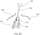
- Fig 8O is a simplified illustration of an IOS measuring a hole made by a drill in accordance with some embodiments of the invention.
- Fig. 8O shows gingiva 807*, bone 811 and a hole 812 in the bone 811, and an IOS head 304 and probe 308.
- Fig 8O shows the IOS head 304 measuring the hole 812, for example a hole 812 made by one or more of various drill(s) in a drilling process before an implant is inserted.
- the probe 308 optionally measures one or more of a depth of the hole 812, a width of the hole 812, a shape of the hole 812 and an inside threading made by the drill.
- the measurements are optionally compared to a desired result corresponding to an implant planned for use and its geometric parameters.
- an optional ball 813 at a tip of the probe 308 optionally has a diameter which is desired for an implant, and potentially enables verifying that the hole 812 is wide enough for the desired implant.
- the measurements are optionally used to measure drill holes prior to implanting an implant, to verify that a drill has reached bone and produced a hole of suitable width, depth, shape, and thread.
- Fig 8P is a simplified illustration of an IOS measuring parameters of a dental implant in accordance with some embodiments related to embodiments of the invention.
- Fig 8P shows an IOS head 304 using a probe 308 measuring parameters of a dental implant 809.
- Example parameters measured by the probe 308 include, by way of some non-limiting examples, a location of the dental implant 809, orientation of the dental implant 809, shape of the dental implant, and similar geometric parameters, optionally relative to adjacent teeth (not shown), and/or relative to a jaw bone and/or relative to gums.
- the measurement is optionally done using a number of known point 810 locations on the implant 809.
- the number of known points 810 is optionally small, for example 6. In some embodiments, 6 known points 810 in a scan are optionally enough to produce a three-dimensional model and correctly register the model relative to a mouth with 6 degrees of freedom (DOF).
- DOF degrees of freedom
- the spatial registration optionally gives up a DOF, for example rotation around a long axis of the implant 809 and 5 known points 810 are optionally used.
- 3 known points 809 are used on an implant
- a hollow cavity shape (not shown in Fig. 8P ) represents the known points, providing a position and optionally an orientation vector for registration.
- a hollow cavity shape (not shown in Fig. 8P ) represents the known points, providing a position and optionally an orientation vector for registration and an addition known point is used in the registration.
- the number of points is selected to enable determining a specific shape of an implant 809 that are enough in order to know the parameters due to the implant synthetic shape.
- the known point 810 locations are optionally any touching point on an implant.
- 3 known points are optionally marked on an implant.
- the 3 known points marked on the implant are not all on a straight line.
- data regarding the relative positions and/or distance between the 3 known points is known, optionally provided by an implant manufacturer.
- the probe is moved to make contact with the 3 known points, the known points are identified, and the implant is optionally registered in space and/or located with a model of the oral cavity based on knowing the size and shape of the implant relative to the locations of the 3 known points.
- the implant is manufactured with probing holes at known locations on the implant.
- the orientation and/or location of the implant is optionally calculated.
- a 1mm distance between 2 points can mean that the 2 points are the points at 12 o'clock and 3 o'clock of the implant (for example this is how the implant was manufactured) and a 2mm distance between 2 points means that the 2 points are points at 3 o'clock and at 8 o'clock, for example.
- the known point 810 locations are optionally configured so that a distance between the locations is greater than N pixels in in an image or scan of the locations.
- the number of pixels N is greater than 2 pixels, or greater than a number N in a range between 2 and 5,000.
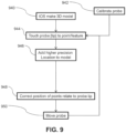
- Fig. 9 is a flowchart of a method of improving IOS mapping accuracy, in accordance with some embodiments of the invention.
- the IOS is used to make an initial 3D model 940 of a feature and/or a portion of the mouth and/or of the whole mouth.
- the probe is used measure 944 at a higher accuracy the feature and/or a sub-region of the mapped area and/or another area.
- the high accuracy measurement is optionally added 946 to the 3D model.
- the high accuracy measurement may be used to correct 948 the location of other points in the model at improved accuracy.
- the probe may be moved 950 and/or further points may be measured 944 as needed.
- the probe may be calibrated 942, before during and/or after scanning.
- an IOS scanner with a probe may be used to determine a locations and/or shape of a surface.
- the probe may be used to touch 944 a point on the surface and/or the precise position of the point touched by the probe may be used to correct 948 the position of the surface.
- the probe may be touched 944 to multiple points on the surface and/or dragged across the surface and/or the points may be added 946 to build a high precision 3D model of the surface.
- the surface may be modelled as a plane and/or a curve.
- multiple points may be defined on the surface (for example by touching 944 each point with the probe).
- the distance between the defined points may be used to define a measure and determine distance along the surface and/or in other parts of a 3D model.
- a fiducial marker for example the tip of the probe
- the precise distance measure of the marker is optionally used to determine distances on the surface and/or to produce a high precision model of the surface and/or to correct 948 the locations of other points to a high precision.
- a calibrated probe is combined with a 3D camera.
- the accuracy of the measurements done with the probe may significantly exceed the initial accuracy of the 3D scanner.
- a processer runs an algorithms that finds the probe location from the scanner location in at least one 3D frame.
- the probe location can be obtained from many 3D points and/or features measured by the scanner in the same frame.
- IOS produce depth maps, for instance using structured light, and/or by aligning multiple images together to get a single 3D model.
- a typical accuracy of a point on a tooth in a model produced by an IOS is for example approximately 30um.
- the overall accuracy of alignment of a single depth map image that contains thousands of points to a 3D model may be significantly better.
- the accuracy of the probe tip with respect to the rest of the model may be 10 ⁇ m instead of 30 ⁇ m.
- this internal alignment of the probe measured point to the rest of the model may increase the accuracy of large areas on the model to within 10 ⁇ m.
- an IOS with a probe may be used measure a tooth prepared for fixed prosthesis (for example a crown for example as illustrated in FIG. 8F and/or an inlay for example as illustrated in FIG. 8B and/or an onlay for example as illustrated in FIG. 8C ).
- the IOS may be used to make 940 an initial 3D model of prepared tooth and/or the area around the prepared tooth.
- the probe is optionally brought in contact with areas of the prepared tooth (for example as illustrated in FIG. 8F ).
- the probe may be used to measure the extent of the shoulder and/or the edges and/or cusps of the prepared tooth.
- the probe may be used to measure closure between a prepared tooth and an antagonistic tooth.
- the high accuracy measurements are optionally used to prepare a more precisely crown, for example a crown that will better fit the prepared tooth and/or better mesh with an antagonistic tooth.
- the data from the probe combined with the data from the camera may be used to improve the accuracy of an STL file. For example, accurate locations of multiple points in a single depth mapped image may be computed based on their relationship to sample points in the image that were touched by the probe and/or measured using the probe. The accurate locations may be added to the STL file and/or used to correct the STL file.
- the data from the probe is optionally combined with data from a prior art dental scanner.
- the measurements from the probe are optionally combined with the measurements of the prior art scanner.
- the prior art scan can provide additional data, for example from areas that were not scanned an embodiment of the present invention, or not scanned well enough.
- Problematic areas that can be scanned with the probe embodiment and that are hard to get using a prior art scanner can be, by way of some non-limiting examples, deep holes like a hole inside an abutment or a space between two adjacent teeth, especially below a finish line of a crown.
- the sample points may be on supragingival areas that are seen by the camera and were measured with the probe (for example as illustrated in FIG. 3A-3F , 8F, 8G, 8C ).
- a portion of the probe (for example the probe tip and/or graduations along the probe) may be used as a fiduciary marker.
- the scale of an image from the IOS may be made more precise.
- improved scaling on the IOS image will allow determining more precise geometric relationships between features and/or higher accuracy location of features.
- a probe tip may be dragged along a surface, for example to measure a line along the surface and/or to get an accurate measure of the roughness of the surface.
- a IOS scanner with a probe is used to measure a surface for placement of an onlay.
- an onlay implant or graft is fixed to the bone with pins/screws, for example to obtain primary fixation. For example this may be used in cases where there is not enough volume of bone for the conventional implant and/or where the dentist decides not to use augmentation procedure surgery.
- an onlay will be produced via 3-D printing. For example, printing of titanium or CoCr using laser sintering.
- data to produce the implant is obtained from a CT scan of the bone.
- an IOS scanner including a probe in accordance with an embodiment of the current invention may be used to produce a precise STL file of the outer surface selected to be underneath the onlay, for example a surface of the bone.
- the data from the STL file is combined with the data from the CT scan to raise the accuracy of the final STL file.
- the combined CT, STL data is optionally used to determine the location and/or the size of the prosthesis and/or fixating screws of the prosthesis.
- the IOS scanner probe in these cases will enable to produce a more accurate prosthesis.
- an onlay will be mounted to exposed bone or tooth, for example measurement may be similar to a crown described above.
- an onlay will be fitted to parts of a bone or tooth that are obscured.
- measurement for such an onlay may be similar to measurements for an implant.
- a CT and/or a STL file will be sent to a manufacturer who will produce the onlay and send it to the dental practitioner.
- data from a IOS scanner will be sent directly to an on-site 3D printer.
- on-site printing or CNC may make it possible to reduce the time and/or number of dental visits for producing an implant and/or onlay.
- an IOS scanner with a probe may be used to measure a plaque layer or calculus, for example as illustrated in FIG. 8H .
- the probe may be used in conjunction with the IOS sensor to locate and/or measure and/or evaluate exposed plaque deposits.
- a probe may be used to explore a periodontal pocket for example to determine the depth of the pocket, for example as illustrated in FIG. 8A and/or FIG. 13A and/or FIG. 13B .
- the probe may be used to locate, measure and/or evaluate plaque deposits under the gum line. For example, the tip of the probe may be dragged along an obscured surface.
- the presence of scales may be revealed by changes in roughness of the surface that are apparent in the 3D map made based on images of the position of the probe as it passes along the surface.
- a sensor may be provided near the tip of the probe.
- the probe tip and/or sensor may be inserted into the periodontal pocked.
- the sensor data may be used to locate, measure and/or evaluate a plaque deposit.
- the IOS sensor may be used to evaluate the depth to which the probe is inserted in a periodontal pocket and/or the scale of movements as a probe is dragged along a surface.
- an IOS sensor may be used to determine a location of a probe (for example the IOS may sight and/or locate an exposed part of the probe, the location a concealed part of the probe and/or a sensor on the probe may be calculated for example based on the location of an exposed portion of the probe and the geometry of the probe).
- the sensor on the probe is optionally used to evaluate a concealed feature, for example including a subgingival deposit.
- an IOS scanner and probe may be used to detect measure and/or evaluate tooth abrasion, for example as illustrated in FIG. 8E .
- a probe may be fitted with a gauge to measure deposits of scale and/or plaque.
- a gauge may include an ultrasonic range finder.
- deposits may be measured above the gum line (supra gingival) and/or below the gum line (sub gingival). Measurement techniques listed above with respect to plaque may be applied to measure abrasion and/or scale deposits.
- a probe may include an ultrasonic scaler.
- a tooth may be measured and/or deposits may be evaluated.
- the scaling may be directed using images of the IOS while the probe is being used to remove the deposits.
- IOS images and/or other sensor data may be used evaluate the progress of the scaling.
- Fig. 10 is a flow chart illustrating post placement measuring of a prosthesis in accordance with an embodiment of the current invention.
- a probe may be used to increase accuracy of measurement of the location and/or fit of a the prosthesis.
- the probe tip may be placed in contact with the prosthesis and/or dragged along a surface of the prosthesis, for example to determine an exact location of the feature.
- the probe (and/or a tip thereof) may be placed on 1052 and/or dragged along a joint where a prosthesis contacts a native structure.
- the fit of the prosthesis at the joint (for example a finish line of a crown) may be evaluated and/or the placement of the prosthesis may be evaluated 1054, for example as illustrated in FIG.
- the location of the probe may be determined using IOS images and/or by matching features in an STL file, This may improve measurement of the location of mismatched features of the prosthesis and the native structure.
- the probe may be used to evaluate 1055 closure and/or positioning of prosthesis (for example a crown) with respect to antagonistic teeth. Measurements are optionally made of exposed features and/or caught in the IOS image (for example when testing the positioning of a crown and/or overlay). Alternatively or additionally measurements may be made of fit of concealed features, for example the matching of an implant and/or an extraction cavity.
- measurements of concealed objects are made while touching the object with a probe and/or using a probe mounted sensor.
- the height of a prosthesis may be evaluated 1054 and compared to an expected height, for example to determine if the prosthesis was properly fit.
- a probe may be used to measure a feature of a prosthesis and/or a prepared location for placement of the prosthesis. For example, a thread width of a screw thread and/or matching of threads may be measured in situ.
- a IOS with a probe may be used to measure features of a man-made element itself (for example size, surface quality of a prosthesis).
- the IOS with a probe may be used to measure the placement of the man-made element with respect to a natural element (for example bone, teeth, gingiva, etc.) and/or with respect to other man-made elements.
- a natural element for example bone, teeth, gingiva, etc.
- an IOS with a probe may be used to measure a dimension on an inlay and/or the insert height of an implant to the bone.
- Fig.11 is a flow chart illustration of a method of measuring a recess in an oral cavity with an IOS including a probe in accordance with an embodiment of the current invention.
- the inside of the recess may be obscured from an IOS scanner.
- a probe may be inserted 1144 into a recess and/or contact points in the recess, for example to measure a location on the walls of the recess and/or depth of the recess 8D.
- a sensor and/or light source on a probe may be positioned 1145 to get a better view of the recess, for example as illustrated in FIG. 8B .
- the senor 1145 of the probe may be positioned to view a recess from outside the recess.
- the sensor may be inserted 1144 into a recess to view from the inside (for example inside a periodontal pocket as illustrated for example in FIG. 8F .
- a prosthesis for example an implant and/or an inlay and/or an onlay, may be inserted 1144 into a recess.
- the prosthesis may be inserted 1144 into a recess in a tooth and/or into a recess in a bone and/or into a recess in the gingiva.
- the probe may be used to measure a post extraction socket, for example as illustrated in FIG. 8D .
- measurement data may be stored and/or sent to a manufacturer when ordering the prostheses.
- data from the measurements may be sent directly to a 3D printer to produce prosthesis.
- the prosthesis may be printed on-site and/or in real time.
- a dentist may measure and place prosthesis.
- the scanner may include a processor and/or a network adaptor allowing it to directly communicate with a printer.
- a probe may be inserted 1144 inside of a recess to measure the recess and/or determine a health condition and/or treat a health condition.
- a probe may be used to explore and/or clean a root 863 for example as illustrated in FIG. 8I .
- the probe may be used to measure root apex depth.
- a probe of an IOS may perform 1167 a treatment.
- a probe for probing a root may include a channel.
- the channel may be used to sterilize the root (for example by introducing a chemical and/or by heat or a laser) alternatively or additionally a channel may be used to apply a vacuum to clean the root.
- the IOS may be used to map the location and/or evaluate the effect of the treatment.
- an embodiment of the current invention may be used to characterize the shape of a post extraction socket in the bone to prepare an exact fitting implant,
- the root of a tooth may be engaged in the alveolar bone. After extracting the tooth and/or root, a cavity may remain in the bone.
- the cavity may be referred to herein as a "socket".
- the anatomy of the socket may correspond to the root that was previously held in it.
- measurements and/or a 3D map and/or 3D printed prosthesis may be produced quickly using an embodiment of the current invention.
- the pre preparation measurement of the bone and/or 3D map quickly enough to leave the dentist free to prepare that bone in the same sitting.
- a post preparation map of the bone may be made at the same sitting. and/or design for the prosthesis may be made in the same sitting.
- after preparing post preparation measurement of the bone production of the prosthesis (for example by 3D printing) and/or attaching of the prosthesis may be done in the same sitting.
- using an embodiment of the present invention the number of sitting required to measure, prepare, produce and/or attach a prosthesis may be reduced. Optionally this shortens the time and/or cost of installing a prosthesis.
- Some dental implants may be limited to a cylindrical shaped. In some cases, the cylindrical shape will not correspond to the socket anatomy which may for example be conical shaped. In case of multi rooted tooth such as a molar there may be a more significant discrepancy between the socket and a conventional prosthesis. Placing such an implant may include drilling and/or augmenting the bone.to produce a properly shaped socket for mounting the implant. In accordance with an embodiment of the current invention measuring of a socket and/or production of a custom insert is facilitated. In accordance with an embodiment of the current invention measuring of a socket and/or production of the insert is facilitated.
- a bone has appropriate height, but has insufficient width to receive a conventional implant.
- a dentist and/or a surgeon can create a cavity in the bone, for example resembling a groove along the bone.
- a 3D map giving precise information about of the shape of the bone may be obtained using an IOS with a probe, for example to produce a 3D map.
- a surgeon may use the 3D map to plan where and/or how to connect the onlay to the bone.
- the 3D map may be used to determine where there is sufficient bone to connect to the onlay and/or what kind of connection is possible between the onlay and the bone.
- a surgeon may use the 3D map to plan where to form the groove and/or what size to make the groove and/or what shape to make the groove.
- a 3D map of the bone will be prepared using an embodiment of the present invention after the bone has been prepared.
- the 3D file obtained by the probe and scanner may be used to produce an implant that precisely fits the outer surface of the bone and/or precisely fits into the groove.
- the current invention facilitates production and/or fitting of a custom onlay that fits on the outer surface of the bone and/or a natural cavity and/or a cavity drilled by the dentist. For example this may enable the dentists to use an onlay in compromised bone conditions without bone augmentation and/or with less augmentation than conventional procedures.
- the custom prosthesis may be attachable to bones that were not able to support a conventional implant and/or a custom implant may be more stable than a conventional implant.
- using the probe and the scanner may facilitate immediate implantation.
- High accuracy mapping may improve primary fixation in some embodiments.
- surgery may be less complicated and/or less technical sensitive and/or suitable for less trained and experience dentists.
- Using an IOS probe combination may eliminate the need to augment the bone. In some cases this will lower the price of the surgery and/or reduce the side effects (swelling and infections).
- Measurement of the socket at higher resolution with an IOS probe may in some embodiments produce a better fitting prosthesis and/or eliminate the need to drill into bone for example to fit the prosthesis.
- a reduced time and primary fixation procedure may replace a multi-step implantation process that would require 6-8 weeks of recovery after the tooth extraction, in order for the socket to heal and be ready for the surgery of implant insertion.
- inserting the implant may include primary fixation of the implant in the bone.
- an IOS with a probe is used to characterize the shape of a post extraction socket in the bone.
- STL file obtained from the scanner, can be exported to create an well-fitting implant to the anatomy of the socket.
- the IOS with probe may be used to map multiple cavities in a socket of a multi-rooted tooth.
- Creating a well-fitting implant is optionally done via 3D printing.
- the resulting implant is optionally attached to the bone with reduced preparation of the bone, for example without drilling.
- Using the probe optionally facilitates immediate implantation in some cases. For example this may shorten the time needed between the extraction of the tooth and delivering the final prosthesis and/or reduce the number of surgical procedures. In some embodiments the above may result in faster, less costly procedures, more comfort to the patient and/or more simplicity to the dentist.
- Fig. 12A is a flowchart of a method of intraoral mapping soft tissue in accordance with some embodiments of the invention.
- an IOS including a probe may be used to map out the surface of the lining mucosa.
- This data may be used for producing and/or fitting a removable prosthesis, for example to treat edentulism.
- an IOS with a probe may be used to scan the oral mucosa. Scanning the mucosa may be challenging due to lack of features (for example when there are no teeth). In some embodiments, the probe, touching the mucosa can improve the ability to produce an STL file and/or improve its accuracy.
- the probe is optionally used as a feature which can be identified and located in an oral scan or map produced by the IOS.
- the probe is optionally used as a feature in a map or scene with only few features, by way of a non-limiting example in a scan of a partially edentulous arch.
- the probe, touching the gingiva is optionally used as a feature that the processing unit can use in order to create a model, potentially a more accurate model than previously.
- the probe is placed at a stationary place while the scanner orientation is changed, to capture different areas around the probe.
- Such example embodiments potentially produce a more accurate model, optionally based on more features in a scene.
- Fig. 12B is a simplified illustration of a probe used as a feature in an IOS scan in accordance with some embodiments of the invention.
- Fig. 12B shows an IOS head 304 304' 304" and a probe 308 308' 308", and example teeth 1202 in an example intra-oral section 1204 to be scanned.
- Fig. 12B shows the IOS head 304 304' 304" scanning the intra-oral section 1204 to be scanned from several angles, by way of a non-limiting example three angles as shown in Fig. 12B .
- a tip 1206 of the probe 308 is optionally kept at one specific location in the intra-oral section 1204 to be scanned, and optionally provides a static position, enabling one method of identifying a same location in scans from the three angles.
- teeth 1202 are optionally used to identify same location(s) in scans from the three angles.
- the IOS head 304 is manipulated to move between the three positions 304 304' 304".
- the 3 positions are optionally used, by way of a non-limiting example, to capture image(s) of a first tooth 1202 and a location of the probe tip 1206, then optionally to capture image(s) of the probe tip 1206, then optionally capture image(s) of the probe tip location 1206 and a second tooth 1202.
- known locations of the first tooth 1202 and the second tooth 1202 are optionally used to correctly register a location of the probe tip 1206 relative to the teeth 1202.
- the location of the first and the second teeth are optionally also registered in a 3D model of the mouth.
- an IOS for mapping the surface of the lining mucosa the probe has an enlarged tip 372.
- tip 372 may be formed into a sphere with large diameter for example in the range of 1-5 mm and/or 5-10 mm and/or 10-20 mm.
- a sphere may be mounted on tip 372. The sphere may facilitate better mapping of the surface of the lining mucosa features which are relevant for removable prosthesis good fit.
- widened tip may be made out of steel and/or hard rubber and/or plastic.
- a physical property of the tissue may be tested 1256.
- the elasticity of the surface of the lining mucosa is measured 1256 or mapped.
- the surface of the lining mucosa is scanned with said probe.
- scanning may include applying low force with the probe during scan of the surface of the lining mucosa and or measuring 1256 the deformation of the surface.
- the applied force may range between 0.001 to 0.1 Newton and/or between 0.01 to 0.1 Newton and/or between 0.01 to 0.1 Newton and/or between 0.1 to 1 Newton.
- the applied force may be measured from the probe deflection.
- the applied force may be measured using force sensor on the probe (for example as illustrated in FIGs. 3D-3F ).
- the deformation of the tissue as the sphere is pushed into the surface of the lining mucosa may be measured, for example, using the 3D scanner. From the combination of the deformation of the tissue and the applied force the elasticity can be computed.
- the vitality of an area may be measured, for example using the flow of the blood out and into the area when applying and removing the force.
- the changes in the blood supply is optionally measured using the camera to capture changes in color due to the changes in the quantity and/or pressure of blood present.
- a depth of soft tissue may be measured 1258.
- a sharp probe may be pushed through soft tissue until it reaches a hard feature (for example bone or tooth). The depth of penetration can then be recorded as the depth of the tissue.
- the resistance to penetration of the tip may be measured.
- FIG. 13A is a flow chart illustrating use of a IOS including a probe to explore a periodontal pocket in accordance with an embodiment of the current invention.
- a probe will be inserted into a periodontal pocket.
- the pocket will be explored 1344 using the probe.
- data will be collected 1359 from the IOS and/or probe mounted sensors. The 3D location of the probe and/or areas being explored is optionally calculated using the IOS.
- data and position information will be used to evaluate 1347 periodontal health.
- data will be collected 1359 from a probe based sensor (for example an optical sensor 1312 as illustrated for example in FIGs.
- a force sensor for example sensors 322a-322c as illustrated in FIGs. 3D-3F and/or a remote sensor for example an external x-ray imager and/or an external sensor connect to the probe for example through an optical fiber as described for example in relation to FIGs. 5A and 5B )
- the probe may be inserted to the end of the pocket.
- the IOS will image an exposed portion of the probe, for example extending out of the pocket and/or the IOS will calculate 946 the position of the probe and/or depth of the pocket may be measured.
- the probe will be used to exert pressure on an object.
- the IOS may collect 1359 data about the movement of the object and/or tissue and/or teeth due to forces exerted by the probe. For example, pressure may be exerted on an object inside the periodontal pocket.
- data about the force exerted by the probe on an object may be collected 1359 using force sensors on the probe (for example as described with respect to FIGs. 3D-3F ) and/or the IOS may collect 1359 data on bending of the probe (for example from images of the probe) the force exerted is optionally calculated based on bending of the probe apparent from IOS images.
- periodontal health will be evaluated based the position of probed objects, the size of the pocket and/or the stiffness and/or softness of teeth and/or other tissue.
- a sensor on the probe will be used to collect 1359 data on periodontal health.
- the probe may include an optical sensor (for example sensor 1312 illustrated in FIG. 13B ) near the tip thereof.
- the sensor may include, for example a large FOV imaging sensor and/or a small FOV sensor or the like.
- optical sensing at the tip may be via an optical fiber (for example through a channel as illustrated in FIG. 5A-5B ) transmitting light to a remote sensor.
- the images may be evaluated 1347 to diagnose inflammation and/or bleeding (for example from the color of teeth and/or other tissue).
- Data from a sensor on the probe and/or from the IOS sensor may be used to locate a CEJ (cement to enamel junction) and/or a mukoginigival line for example based on the color difference.
- the position of measured features is calculated 946 and/or combined with a 3D model.
- the 3D data optionally is used to evaluate 1347 the location and/or extent of periodontal conditions.
- the 3D data may be used to output a personalized periodontal chart for example as illustrated in FIG. 14 .
- the periodontal chart is optionally generated automatically.
- the probe may also be used to collect 1359 data and/or the IOS may be used calculated position 946 and/or map CAL (clinical attachment level/loss).
- the probe may also be used to collect data 1359 on furcation involvement.
- the probe may also be used to collect 1359 data on subgingival plaque.
- plaque may be to identified and/or measured using fluorescence.
- the probe may include optical fibers and/or probe mounted sensors and/or illumination sources to measure fluorescence.
- full dental charting which lists and describes the health of teeth and gums is automatically produced.
- Periodontal charting includes one or more, and up to six measurements (e.g. in millimeters) that are taken around each tooth.
- the charting is done during dental checkups, by the hygienist and/or the dentist.
- the charting provides a graphic method of organizing and presenting information about a patient's dental health, i.e. it is a graphical tool for organizing information about teeth and gums.
- the chart includes a graphical, or pictorial, representation of the patient mouth.
- the chart shows one or even all of the teeth as a real image, optionally using 2D or 3D graphics, optionally using color and/or shading.
- the chart includes additional information on the condition of the teeth and gums, such as, for example: areas of decay (cavities), missing teeth, depths of the gum pockets, bleeding points during probing, gum recession, abnormalities in the teeth, such as rotations, erosion, or abrasions in the teeth or enamel, damage to the teeth, presence of crowns, bridges, implants, and fillings, attachment of the teeth to the gums, movement and/or mobility in the teeth, bleeding in the gums, exposed teeth furcation, presence of suppuration.
- the chart information is stored in a memory as a record, optionally in the cloud.
- stored chart information is optionally compared to current chart information, for example during a dental checkup, potentially enabling progress of dental health to be tracked.
- the charting process optionally begins by finding a scanned tooth number so the measured parameters can be attributed to a correct scanned tooth.
- a hygienist and/or a dentist optionally examines the teeth, optionally by probing gums to check the depths of the gum pockets. In some embodiments up to six readings per tooth are recorded in the periodontal charting process.
- the IOS automatically identifies the probing location around the tooth, and optionally display a pocket depth in the chart accordingly.
- the IOS optionally identifies the mobility level and adds the mobility level to the chart.
- movement of a tooth is optionally obtained by applying force, optionally lateral force, to a crown area of the tooth, optionally with a tip portion of the probe, and measuring and/or calculating movement of the tooth relative to a model or to known points in an image and/or by measuring and/or calculating a bending of the probe.
- a color image obtained from the IOS is used for detection of parameters such as the CEJ, mucogingival junction, bleeding, suppuration, presence of crowns, bridges, implants, and fillings.
- a 3D model obtained from IOS with or without the addition of the probe information is optionally used for detection of tooth furcation and the free gingival line.
- a clinical attachment level is optionally automatically presented by calculating relevant data, such as, for example, pocket depth, free gingival line, CEJ, mucogingival line.
- relevant data such as, for example, pocket depth, free gingival line, CEJ, mucogingival line.
- Data from an X-ray image is optionally combined in a calculation, such as, by way of a non-limiting example, a length of a tooth and/or a root of a tooth.
- the probe is used to detect the feature, for example furcation, even in the presence of blood.
- the detection is optionally performed by touching the furcation with the probe, or by detecting the CEJ using a color difference between enamel and cement/cementum in an image optionally captured, optionally by a fiber, optionally through the probe, optionally while air pressure clears a view between the fiber and the enamel and/or cementum.
- FIG. 13B is a schematic illustration of a IOS including a probe 308 exploring a periodontal pocket 1362 between a tooth 309 and gums 1307.
- a tip of a probe 308 will be used to explore a periodontal pocket 1362.
- information gathered by the probe will be integrated with 3D mapping.
- the device may automatically compute pocket depth as a function of position.
- the IOS may track the position of probe 308 over time and/or find the maximum insertion depth as a function of a 3D location and/or compute a spatial distribution of pocket depth.
- the user may signal to the IOS when probe 308 has reached the end of the pocket and/or reaching the end of a pocket may be registered by a pressure sensor.
- a probe 308 may include a tool.
- an optical sensor 1312 and/or a light source may be provided near the tip of probe 308.
- sensor 1312 is used to detect and/or identify periodontal features.
- optical data gathered by sensor 1312 may be combined with data gathered by IOS sensor 306 to map features in 3D and/or to find relationship between exposed features and periodontal or unexposed features.
- FIG. 14 illustrates a periodontal chart.
- an IOS with a probe will be connected to a processor and/or an output device that will automatically generate the table from sensor data and/or 3D IOS information.
- the processor will store a 3D map of dental features (for example teeth) and/or data on periodontal conditions and/or their locations.
- a processor may store data on periodontal conditions.
- periodontal conditions may be determined by the processor based on probe measurements and/or sensor measurements for example as described in the description of FIG. 13A , 13B .
- the processor will determine the location of the measured condition based on output of the IOS sensor and/or in relation to a 3D map (for example an STL file). For example, the probe location when a particular condition was measured will be correlated with the locations of various teeth to determine the particular tooth and/or on particular face of the tooth on which the condition was measured.
- the probe location at the time of measurement is optionally detected by an IOS sensor and/or stored by the processor.
- the resulting correlation between dental structures and measured conditions may be output as a periodontal chart listing detected conditions and/or the location of the conditions on various intra-oral features for example as illustrated in FIG. 14 .
- IOS complementary metal-oxide-semiconductor
Description
- This application is a
PCT application, published as International Patent Application Publication No. WO2019/008586 , claiming priority fromU.S. Provisional Application number 62/528,496 filed on 4 July 2017 - The present invention, in some embodiments thereof, relates to a dental probe, optionally provided as part of or an attachment for an intra oral scanner (IOS) and/or optionally providing imaging or sensing or other functionality.
- U.S. Patent Publication No.
US2017/007377 which states "A method for measuring regions of a tooth in a mouth including: measuring at least one surface point on a surface of the tooth with respect to an element mechanically coupled to said surface point; determining a location of at least one visible reference mechanically coupled to said surface point with respect to said element; estimating a location of said surface point with respect to said visible reference. A device used for such measuring may include a main body comprising a final optical element of an imager which defines an optical field of view directed in a first direction; and a measurement element coupled to said main body extending generally in said first direction; where a tip of said measurement element is sized and shaped to be inserted between a tooth and adjacent gingiva; where said optical field of view is sized to image at least part of a tooth." - U.S. Patent Publication No.
US2016/120615 which states "Devices and methods for ultrasonic dental treatment are described, wherein the devices and methods can comprise a flexible array of cooperative ultrasound transducers. The array can contain individual ultrasonic transducers that can perform both functions of emitting and sensing. The transducers can have the ability to interchange their functions from emitting to sensing. The transducers can cooperate in providing an ultrasound treatment and each transducer can be independently controlled by an external source controller. An ultrasound system is provided comprising: an ultrasound transducer sensor array operable to emit or sense ultrasound, wherein the timing and intensity of emission may be controlled by an electronic controller based on a feedback signal from the sensors. In addition the ultrasound system can also have the ability to sense coupling to a treatment tissue. This ability to sense proper coupling can improve the efficacy of the treatment." - U.S. Patent Publication No.
US2009/306506 which states "A device (10) for acquiring data in the mouth of a patient, wherein the device (10) comprises an ultrasound sensor (20) and a support structure. The ultrasound sensor (20) is stored by means of the support structure when not in use and contains ultrasound deflection means (12) which are movable. A coupling body (21) is provided, which is arranged between the ultrasound deflection means (12) and a tooth area (1, 2, 3) or remaining tooth area to be swept over Excitation signals (14) are sent to the ultrasound sensor (20) and the ultrasound deflection means (12) are moved in order to thus produce an ultrasonic wave which sweeps over at least part of the tooth area (1, 2, 3) or remaining tooth area." - U.S. Patent Publication No.
US2007/037125 which states "This invention includes a method and a device for measuring a tooth. The method includes generating an ultrasonic impulse, which is echoed off of an area of the tooth. By analyzing the echo, the geometry of the tooth can be determined." - The invention is defined in
claim 1. Further aspects and preferred embodiments are defined in the appended claims. Aspects, embodiments and examples of the present disclosure which do not fall under the scope of the appended claims do not form part of the invention and are merely provided for illustrative purposes. Furthermore, the methods presented in the present description are provided for illustrative purposes only and do not form part of the present invention. - Unless otherwise defined, all technical and/or scientific terms used herein have the same meaning as commonly understood by one of ordinary skill in the art to which the invention pertains. Although methods and materials similar or equivalent to those described herein can be used in the practice or testing of embodiments of the invention, exemplary methods and/or materials are described below. In case of conflict, the patent specification, including definitions, will control. In addition, the materials, methods, and examples are illustrative only and are not intended to be necessarily limiting.
- Some embodiments of the invention and some embodiments related to embodiments of the invention are herein described, by way of example only, with reference to the accompanying drawings. With specific reference now to the drawings in detail, it is stressed that the particulars shown are by way of example and for purposes of illustrative discussion of embodiments of the invention. In this regard, the description taken with the drawings makes apparent to those skilled in the art how embodiments of the invention may be practiced.
- In the drawings:
-
FIG. 1A is a block diagram showing of an IOS including a laterally extending probe, in accordance with some embodiments of the invention; -
FIG. 1B is a schematic showing of an IOS including a laterally extending probe, in accordance with some embodiments of the invention; -
FIG. 2A is a block diagram of an IOS having a probe attachment mounted thereon, in accordance with some exemplary embodiments related to embodiments of the invention; -
FIG. 2B is a schematic showing of an IOS configured to attach a probe thereon, in accordance with some exemplary embodiments related to embodiments of the invention; -
FIG. 2C is a block diagram showing of an IOS having a laterally extending probe with a sensor, in accordance with some exemplary embodiments of the invention; -
FIG. 2D is a block diagram showing of an IOS having a laterally extending probe with a channel, in accordance with some exemplary embodiments of the invention; -
FIG. 2E is a schematic showing of an IOS having a laterally extending probe with an affector, in accordance with some exemplary embodiments related to embodiments of the invention; -
FIGs. 3A-3C are schematic showings of IOS including a laterally extending imaging or sensing probe, in accordance with some embodiments of the invention; -
FIGs. 3D-3F are schematic showings of IOS including a laterally extending pressure sensing probe, in accordance with some embodiments related to embodiments of the invention; -
FIGs. 4A-4C are schematic showings of IOS including a laterally extending probe having a reflector in a field of view of the IOS, in accordance with some embodiments of the invention; -
FIGs. 5A-5B are schematics showings of IOS including a laterally extending probe having a channel therein, in accordance with some embodiments related to embodiments of the invention; -
FIG. 6 is a schematic showing of IOS including a laterally extending probe having an affector, in accordance with some embodiments of the invention; -
FIG. 7A is a schematic showing of IOS including a telescopic probe, in accordance with some embodiments related to embodiments of the invention; -
FIG. 7B is a schematic showing a probe with a tip designed for smooth or gliding movement along an oral surface in accordance with some embodiments of the invention; -
FIGs. 7C and7D are schematics showing an option for release of a probe from an IOS, in accordance with some embodiments of the invention; -
FIG. 7E is an image of an optional tool for release of a probe from an IOS, in accordance with some embodiments of the invention; -
FIG. 7F is a schematic showing a sleeve with a probe that is placed over an IOS, in accordance with some embodiments related to embodiments of the invention; -
FIG. 7G is a schematic showing a probe with a tip including a ball designed for smooth movement along an oral surface in accordance with some embodiments of the invention. -
FIGs. 8A-8K are schematic drawings showing various dental structures which may be measured using an IOS and a probe in accordance with some embodiments of the invention; -
FIG. 8L is a simplified illustration of an IOS measuring gingiva surrounding a dental implant in accordance with some embodiments of the invention; -
FIGs. 8M and 8N are simplified illustrations of an IOS measuring parameters of a dental implant in accordance with some embodiments of the invention; -
FIG. 8O is a simplified illustration of an IOS measuring a hole made by a drill in accordance with some embodiments of the invention; -
FIG. 8P is a simplified illustration of an IOS measuring parameters of a dental implant in accordance with some embodiments related to embodiments of the invention. -
FIG. 9 is a flowchart of a method of improving IOS mapping accuracy, in accordance with some embodiments of the invention; -
FIG. 10 is a flowchart of a method of intraoral mapping for an artificial object, in accordance with some embodiments of the invention; -
FIG. 11 is a flowchart of a method of intraoral mapping a recess, in accordance with some embodiments of the invention; -
FIG. 12A is a flowchart of a method of intraoral mapping of soft tissue, in accordance with some embodiments of the invention; -
FIG. 12B is a simplified illustration of a probe used as a feature in an IOS scan in accordance with some embodiments of the invention; -
FIG. 13A is a flowchart of a method of intraoral mapping of a periodontal pocket, in accordance with some embodiments of the invention; -
FIG. 13B is a schematic showing of a side-looking IOS in a periodontal pocket, in accordance with some embodiments of the invention; -
FIG. 14 is a portion of a chart display optionally provided by periodontal imaging, in accordance with some embodiments related to embodiments of the invention. - The present invention relates to a dental scanner according to
claim 1. - An aspect of some embodiments of the invention relates to an IOS with a laterally extending probe, integral or add-on. In some exemplary embodiments of the invention, the probe is within a field of view of the IOS imager. In some exemplary embodiments of the invention, the probe is used to contact an intraoral surface for providing geometrical or other measurement thereof. In some exemplary embodiments of the invention, a mapping by the IOS is improved by said contact. Optionally or alternatively, the probe contact is used to detect surface properties other than geometry relative to the IOS, for example, tissue stiffness.
- In some embodiments, a probe may have an average width (e.g. diameter) ranging between 0.1 to 0.5 mm and/or between 0.5 to 1.0 mm and/or between 1 to 2 mm and/or between 2 to 4 mm.
- In some exemplary embodiments of the invention, the probe is used to measure one or more of a tooth extraction socket, a drilled socket, a soft tissue surface, a bone surface under soft tissue, a dental implant, a tooth, space between teeth, periodontal pocket, a sub-gingival section of a tooth, a dental abrasion pattern and or a recess in a tooth. Optionally, the measured space is measurable using the IOS, and the probe provides enhanced resolution. Optionally or alternatively, the probe is used to measure surfaces that are not measurable using the IOS, for example, due to field of view limitations thereof.
- In some exemplary embodiments of the invention, the probe laterally extends, for example, at an angle of between 30 and 150 degrees relative to an axis of a handle of the IOS.
- In some exemplary embodiments of the invention, the probe includes an imager, for example, an ultrasound imager (for example a side viewing ultrasonic imager (IVUS) or a Piezoelectric Micromachined Ultrasound Transducer (PMUT) array)), a sensor, for example, an ultrasound sensor or stain sensor and/or a mirror, for example, reflecting a view lateral to the probe to an imager of the IOS.
- In some exemplary embodiments related to embodiments of the invention, the probe includes an effector, for example, a tool for tissue ablation or coagulation.
- In some exemplary embodiments of the invention, the probe includes a channel, for example, for providing a fluid or removing fluid. Optionally, the channel is connected to a reservoir and/or a source, for example, of cement or sterilizing fluid. In some embodiments a channel may have an average cross sectional area along the probe ranging between 0.01 mm2 to 0.1 mm2 and/or between 0.1 mm2 to 0.25 mm2 and/or between 0.25 mm2 to 1. mm2 and/or between 1 mm2 to 25 mm2. Optionally the channel may take up between 1% to 10% and/or between 10% to 30% and/or between 30% to 60% and/or between 60% to 90% of the probe.
- In some embodiments, IOS location measurement uncertainty will be reduced by between 50 to 90%. For example an IOS scanner may have a measurement error of less than 40 µm and/or a location of a feature at a probe tip may be measured with an error of less than 10 µm and/or 5 µm and/or less than 2 µm. One or more points of high accuracy measurements may be used to condition measurements in other locations to decrease measurement uncertainty in regions of the domain where the probe tip was not used for a direct measurement. For example, conditioning on accurately measured points, the error in a region may be reduced to below 5 µm and/or below 10 µm and/or below 20 µm and/or below 30 µm. For example, conditioning may be used to improve the accuracy of a depth mapped image.
- An aspect of some embodiments related to embodiments of the invention relates to measurement of intraoral surfaces using an IOS having a laterally extending probe. In some exemplary embodiments of the invention, the probe tip is atraumatic. Optionally, the IOS is used to position the probe in a 3D representation of the oral cavity or apportion thereof.
- In some exemplary embodiments of the invention, the IOS is used to measure one or more of mucosa, artificial objects (on their own, relative to each other, orientation, and/or relative to natural tissues and/or natural objects of various types), shapes of cavities (e.g., natural, artificial or resulting from tissue extraction), implant shapes, prosthesis shapes, shapes of surfaces that mate with prostheses (e.g., for bone onlay and/or supra-contact).
- In some exemplary embodiments related to embodiments of the invention, measurement is used to determine one or more of teeth closure, abrasion patterns, plaque, post crown inaccuracy and/or root apex depth.
- In some exemplary embodiments related to embodiments of the invention, the probe tip penetrates the gums and can be used to measure gum thickness by comparing pre- and post-penetration positions.
- In some exemplary embodiments related to embodiments of the invention, the probe tip is used to sense non-geometrical properties, for example, elasticity (e.g., using a strain sensor) and/or color (e.g., using an optical detector). In some embodiments, the probe will be used to exert pressure on an object. Optionally, the IOS may collect data about the movement of the object and/or tissue and/or teeth due to forces exerted by the probe.
- An aspect of some embodiments of the invention relates to measurement of intraoral surfaces using both IOS-based photometrics and using contact measurement. Optionally, the two measurements are combined to yield a higher accuracy, for example, a better resolution and/or better coverage of areas difficult to measure using only photometrics. Alternatively or additionally, a probe may include a fiducial marker. Optionally, a probe tip may include a sensor. For example the probe tip may include an imager and/or a linear measurement sensor (for example a laser range finder and/or an ultrasound range finder). Optionally the probe tip sensor may augment IOS measurements in areas that are difficult to measure with a conventional IOS sensor, for example, inside a recess and/or between teeth and/or in an area angled away from the sensor and/or in an obscured area.
- In some exemplary embodiments related to embodiments of the invention, a same measurement tool is used both intraorally and on objects outside of the mouth, for example, a yet-to-be deployed prosthesis.
- In some exemplary embodiments related to embodiments of the invention, intra-oral features are used to identify a location in a model or an image or a scan of a mouth.
- In some exemplary embodiments related to embodiments of the invention, a location of a probe connected to the IOS is used to identify a location in a model or an image or a scan of a mouth relative to the IOS.
- In some exemplary embodiments of the invention, a tip of a probe connected to the IOS is used to identify a location in a model or an image or a scan of a mouth relative to the IOS.
- An aspect of some embodiments related to embodiments of the invention relates to augmenting an IOS with tools for treating tissue and/or assisting in dental treatment. In some exemplary embodiments of the invention, the IOS includes a laterally extending probe which includes one or more longitudinal channels for passage of materials to, from and/or within the intraoral cavity and optionally having an opening at the side and/or tip of the probe. For example, one or more of water, abrasive materials, adhesive materials, and/or filler materials may be provided via such a channel. Optionally or alternatively, the channel is connected to a suction source for material removal.
- In some exemplary embodiments of the invention, such a channel includes an optical fiber for providing therapeutic and/or imaging light.
- An aspect of some embodiments of the invention relates to an IOS having a laterally extending probe which supports side viewing. In some exemplary embodiments of the invention, the probe includes a mirror which reflects light towards an IOS imager component. Optionally or alternatively, the probe includes one or more optical or ultrasonic sensor or imager. Optionally, the imager is a 3D imager and/or software for reconstructing a 3D image form moving imagers is provided at a control station. Optionally a sensor may include an optical coherence tomography OCT system, for example to image areas below the surface of tissue.
- An aspect of some embodiments related to embodiments of the invention relates to a probe may be used in evaluation and/or treatment of periodontal conditions. For example, a probe may be used to measure periodontal pocket depths. Alternatively or additionally, a probe with a sensor may be used to measure a periodontal condition. For example, the probe and/or the sensor may be inserted into a periodontal pocket. For example, the sensor may sense color. For example, a sensor may be used to identify a cemental enamel junction and/or bleeding and/or inflammation. Alternatively or additionally a probe may include a source of ultraviolet light and/or measure fluorescence, for example, to measure subgingival plaque.
- Referring now to the drawings,
Fig. 1A is a block diagram showing of an IOS including a laterally extending probe, in accordance with some embodiments of the invention. In some embodiment the probe includes anIOS imager 106 mounted on ahead 104 of the device. Forexample head 104 may be mounted on ahandle 102. Optionally, a laterally extendingprobe 108 is attached to head 104. In some embodiments, the tip ofprobe 108 is in the field of view (FOV) of imager 106 (for example inFig. 1B a probe 108' is shown in aFOV 116 of an imager 106'). Optionally, the 3D position of the tip ofprobe 108 with respect to imager may be known to a high accuracy. Alternatively or additionally, the tip ofprobe 108 may include a fiducial marker. For example, markings onprobe 108 and/or a size of the tip may be used in estimating location and/or distance to an object and/or size of the object. For example, the size and/or position of the tip ofprobe 108 may be known with an error of less than 5 µm. - In some embodiments, a probe may be made of stainless steel and/or another metal and/or plastic. Optionally the tip of the probe may be sharp. Alternatively or additionally, the tip may be rounded and/or blunt and/or include a widening. For example the widening may have width between 1 to 5 mm and/or between 5 to 10 mm and/or between 10 to 20 mm and/or between 20 to 30 mm.
- In some embodiments, an IOS may include a handle. For example, the handle may be easily griped for example having a width of between 0.5 cm to 5 cm. Optionally,
head 104 is sized for movement inside a mouth, for example a human mouth. Optionally the head has dimensions between 0.5 to 3 cm. For example, a user may manipulate handle 102 to scan the mouth withhead 104 and/orprobe 108. - In some embodiments,
imager 106 has a high enough resolution to produce depth mapped images and/or anSTL file mapping 3D features of an oral cavity with an error of less than 30 µm and/or less than 100 µm and/or less than 10 µm. Optionally,imager 106 includes a light source. For example, the light source may include a structured light and/or a coherent light. - In some embodiments,
probe 108 is used to increase the accuracy of an IOS image and/or a STL mapping made from the image. Alternatively or additionally, havingprobe 108 on a scanner may save time of a dentist by facilitating producing an IOS scan while the dentist probes, checks and/or treats dental conditions. Optionally, the IOS will produce a hard record of the procedure. For example, the record may be used for evaluating and/or training of dentists. Additionally or alternatively, the record may be useful to as evidence in cases of malpractice and/or for evaluating the efficacy of interventions and/or improvements therein. Additionally or alternatively, the record may be used to evaluate progress of a procedure and/or condition and/or plan follow up. Alternatively or additionally, probe 108 may have functions that improve imaging, for example of difficult to sight surfaces (for example smooth and/or low reflectivity surfaces and/or surfaces that are obscured and/or located in a position which is difficult to reach at a good imaging pose). -
Fig. 1B is a schematic diagram showing of an IOS including a laterally extending probe 108', in accordance with some embodiments of the invention. For example, a handle 102' and a head 104' may have along axis 103. Optionally probe 108' is straight. Alternatively or additionally, a probe may be curved. For example, probe 108' is mounted perpendicular toaxis 103. Alternatively or additionally, probe 108' is mounted at an angle between 45 to 135 degrees toaxis 103. -
Fig. 2A is a block diagram showing of an IOS having a probe attachment mounted thereon, in accordance with some exemplary embodiments related to embodiments of the invention. In some embodiments, an IOS scanner may include amount 210 for attaching aprobe attachment 208. For example, mount 210 may include a snap in mount and/or a screw in mount and/or a protrusion and/or a locking switch and/or a locking pin and/or a tightening element (for example a screw). - In some embodiments an IOS with a
detachable probe 208 may include a calibration procedure to determine the position and/or size of the tip ofprobe 208. Optionally,probe 208 may be part of a exchangeable set of tools that may serve different functions and/or may have different shapes and/or sizes for example for patients having larger and/or smaller mouths and/or whose teeth are looser and/or tighter. Optionally, the IOS may be used withprobe 208 unattached for conventional IOS scanning and/or withprobe 208 attached for scanning and/or otherfunctions using probe 208. -
Fig. 2B is a schematic diagram showing of an IOS having a probe attachment mountable thereon, in accordance with some exemplary embodiments related to embodiments of the invention. For example, the IOS includes a threaded mount 210'. Mount 210' secures one of a plurality of different probes for example a straight probe 208' and/or abent probe 208". For example,thread 225 of theprobe 208', 208" may connect to the mount 201' - In some embodiments, a probe 208', of a first shape may be used for one part of the mouth while a
probe 208" of a second shape may be used for a different part of the mouth. For example, astraight probe 208 may be used for the facial side of front teeth while an angled probe ', 208" may be used for the lingual side. Optionally, changing the probe will allow use of the IOS with the probe to scan an entire mouth. -
Fig. 2C is a block diagram showing of an IOS having aprobe 108 with asensor 212 thereon, in accordance with some exemplary embodiments of the invention. For example, a probe mountedsensor 212 may be used to image and/or measure a region that is not accessible to theIOS sensor 106. Alternatively or additionally a probe mountedsensor 212 may be used to monitor progress of an intervention. - In some embodiments, a probe mounted
sensor 212 includes an imager and/or a range finder. In some embodiments, an imager may include an ultrasound imager an optical imager (for example a monochrome imager and/or a multi-color imager and/or an ultraviolet UV imager and/or an infrared IR imager and/or an OCT imager). Optionally, a probe mounted imager may be used along withimager 106 of the IOS to make a stereoscopic and/or 3D image of an object (for example the two imagers may have overlapping fields of view). In some embodiments, a range finder may include a laser range finder and/or an ultrasonic range finder. - In some embodiments, a probe mounted
sensor 212 may include a force sensor. For example, force on aprobe 108 may be measured by a pressure sensor for example near theprobe 108 tip. Alternatively or additionally, force on a probe may be measured by a strain sensor for example on a shank ofprobe 108. Alternatively or additionally, a force sensor may be located at the joint between the probe andhead 104. Alternatively or additionally pressure on a probe may be estimated by measuring deformation (e.g. elastic bending) of the probe. For example, deformation may be evaluated from images produced by the IOS. For example, a force sensor may be used to evaluate the stiffness of a structure (for example a tooth and/or a bone) and/or the softness of a structure (for example gums and/or mucosa). For example, softness may be evaluated by correlating deformation of the tissue with the force applied. -
Fig. 2D is a block diagram showing of an IOS having alateral probe 108 including achannel 214, in accordance with some exemplary embodiments of the invention. Optionally achannel 214 is hollow and/or connected to areservoir 213. For example, fluid inreservoir 213 may be to introduce into a zone being mapped by the IOS and/or explored withprobe 108. For example, a drug may be introduced to treat a condition and/or reduce pain. Alternatively, a cleaning fluid (for example water) may be introduced throughchannel 214. Alternatively or additionally an abrasive compound may be introduced throughchannel 214, for example for polishing and/or grinding oral features. Alternatively or additionally channel 214 may be used to suction fluid out from a zone being mapped by the IOS and/or explored withprobe 108. Alternatively or additionally,channel 214 include an optical fiber for introducing light into and/or viewing a zone and/or a zone being mapped by the IOS and/or explored withprobe 108. Alternatively or additionally,channel 214 may include an optical fiber. For example, the optical fiber may be used for channeling light to a sensor and/or an imager. Alternatively or additionally, a tool may pass throughchannel 214. For example, wires and/or a tissue ablator may be passed throughchannel 214 to affect tissue in an oral cavity. Optionally an optical fiber may be used to pass a laser signal for tissue ablation and/or cutting oral features. -
FIG. 2E is a block diagram illustration of an IOS having alateral probe 108 and anaffector 215. For example, anaffector 215 may include an ablator. Optionally, apower source 217 supplies energy toaffector 215. For example,power source 217 and/oraffector 215 may be controlled by a controller for example including a processor. -
Figs. 3A-3E are schematic illustrations of IOS including a laterally extending imaging or sensing probes, in accordance with some embodiments of the invention. -
FIG. 3A is a schematic illustration of aprobe 308 including animager 312a in accordance with an embodiment of the current invention. Optionally, a field ofview 316b ofsensor 312a ofprobe 308 overlaps with a field ofview 316a ofimager 306 of the IOS. - In some embodiments,
imager 312a will face laterally away from a side ofprobe 308. Optionally,imager 312a is used to image difficult to reach locations. Forexample imager 312a may improve accuracy of an imaging of a surface angled away from theIOS imager 306, for example a side view of a steep wall oftooth 309. Optionally the probe may be moved for scanning a structure withimager 312a, for example as illustratedarrow 318. Alternatively or additionally,imager 312a may be used to view subgingival features. For example, measured features may include inflammation, and/or calculus (for example the location and extent and/or thickness) and/or plaque. For example, the tip of the probe and/orsensor 312b may be inserted into a periodontal pocket to make a measurement. In addition to and/or alternatively, a sensor may be directed along the axis ofprobe 308. -
FIG. 3B is a schematic illustration of aprobe 308 including anarrow FOV sensor 312b in accordance with an embodiment of the current invention. Optionally, asensor 312b is used to measure a feature in a field ofview 316a ofimager 306 of the IOS. - In some embodiments,
sensor 312b will face laterally away from a side ofprobe 308. Optionally,sensor 312b is used to measure features in difficult to reach locations. Optionally the probe may be moved for scanning a structure withsensor 312b, for example as illustratedarrow 318. Alternatively or additionally,sensor 312b may be used to detect and/or identify and/or measure subgingival inflammation, and/or calculus and/or plaque. For example,sensor 312b may include a range finder and/or a color measuring sensor and/or a reflectivity measuring sensor. For example, whilesensor 312b is identifying features,IOS sensor 306 may be used to map the location and/or extent of the feature. For example, the location of plaque and/or calculus may be entered into a 3D model of the mouth. -
FIG. 3C is a schematic illustration of an IOS including probe having a plurality of sensors in accordance with an embodiment of the present invention. For example,probe 308 is shown with threesensors view view view view view tooth 309. For example, a surface having a length ranging between 1 to 2 mm and/or between 2 to 8 mm and/or between 8 to 15 mm and/or between15 to 30 mm. Alternatively or additionallysensors narrow FOV - In some embodiments, one or more of the
sensors - In some embodiments,
sensors -
FIGs. 3D ,3E and 3F are schematic illustrations of alternative embodiments of a scanner including a pressure sensor. For example, a probe may include a pressure sensor at a distal portion thereof (forexample sensor 322a as illustrated inFIG. 3D ). Alternatively or additionally, a stress sensor may be provided at the base of a probe 308 (forexample sensor 322c as illustrated inFIG. 3F ). Alternatively or additionally, a strain sensor may be including in probe 308 (forexample sensor 322b as illustrated inFIG. 3E ). Alternatively or additionally, pressure may be estimated based on the image produced bysensor 306 of theIOS head 304. For example the pressure on a flexible and/orelastic probe 308 may be estimated based on the location of contact of theprobe 308 and an object and/or the distortion of theprobe 308. For example, an elastic probe may be calibrated to know how much lateral force is required at the tip of the probe to bend the probe to a particular angle. For example, from the direction and location of the point of contact between the elastic probe and an object and from the bending of the probe, the force between the probe and the object can be computed. -
Figs. 4A-4C are schematic showings of an IOS including a laterally extending probe having a reflector in a field ofview 316a of the IOS, in accordance with some embodiments of the invention. For example, a reflector may include a mirror. Optionally a reflector may by straight, and/or curved (for example concave and/or convex). For example, a reflector may give IOS sensor 106 a wider view and/or a view at an additional angle and/or a view at an additional view point than theunmodified view 316a ofsensor 306. Optionally the mirror may be used to get a side view of atooth 309 and/or another structure (for example to see inside a recess for example a cavity in a tooth or gums). - In some embodiments (for example as illustrated in
FIG. 4A ) amirror 424a may be located near a tip ofprobe 308. For example, aportion 316d ofFOV 316a ofsensor 306 may be directed atmirror 424a. Optionally, themirror 424a may allowIOS sensor 306 see anadditional FOV 416a.Optionally mirror 424b may be mounted on apivot 426. For example, pivot 426 may facilitate adjusting of an angle and/orFOV 416a ofmirror 416a. Alternatively or additionally, pivot 426 may facilitate pivotingmirror 424a out of the way of an obstacle while positioningprobe 308. For example, pivot 426 may include an elastic element that allowsmirror 424a to pivot out of the way and/or return to its pose. For example,mirror 424a may be located within 1 mm of the tip ofprobe 308 and/or within 5 mm and/or within 20 mm and/or within 100 mm. - In some embodiments, a mirror may be directed to produce a field of
view 416a approximately perpendicular to the probe and/or approximately perpendicular to the mean direction unmodified FOV of theIOS sensor 306. Alternatively or additionally anangle 423 between the mean direction of the surface of the mirror and the a line from the base of the mirror and theIOS sensor 306 may range for example between 40 to 50 degrees and/or between 50 to 80 degrees and/or between 10 to 40 degrees. In some embodiments,angle 423 may be fixed. Alternately or additionally,angle 423 may be adjustable. - In some embodiments (for example as illustrated in
FIG. 4B ), amirror 424b may be mounted on an intermediate section of theprobe 308. For example,mirror 416b may be more than 100 mm from the tip of the probe. - In some embodiments, (for example as illustrated in
FIG. 4C ) aprobe 308 may have a widened portion at or near its tip. For example, a tip of a probe may form a ball. Optionally, areflective surface 424c of the widened portion may be located in theFOV 316a of theIOS sensor 306. For example,reflective surface 424c may be convex and/or may give an expandedFOV 416b at an angle to theunmodified FOV 316a ofsensor 306. -
FIGs. 5A-5B are schematic illustrations of an IOS including a laterally extending probe having a channel therein, in accordance with some embodiments related to embodiments of the invention. In some embodiments a channel may be partially or completely filled. In some embodiments a channel may be permanently filled. Alternatively or additionally, the channel may be filled with a temporary object and/or the contents of the channel may be changed. For example by a channel may include of fiber, and/or wire. Optionally an opening of channel may be on various locations and/or directed in various directions. For example opening 511b ofchannel 514b is on adistal end probe 308 as illustrated inFIG. 5B . Optionally, opening 511b has a field ofeffect 530b.Optionally probe 308 is straight and/or field ofeffect 530b is directed along the long axis ofprobe 308. Alternatively or additionally, opening 511a ofchannel 514a is located on a side of theprobe 308 for example illustrated inFIG. 5A .Optionally probe 308 is straight and/or a field ofeffect 530a is directed laterally with respect to the long axis ofprobe 308. For example, a field of effect may include an area onto which a material is sprayed and/or a field of illumination of a light emitting fiber and/or a field of view of a sensor connected to an optical fiber. Optionally, a channel in a probe may be in fluid communication with areservoir 513 in the head of the device and/or the handle and/or outside the device. Optionally, a channel in a probe may be in communication with a fluid source and/or an energy source outside the device - In some embodiments,
reservoir 513 may contain a material to introduce into the mouth and/or may serve to store material removed from the mouth. Alternatively or additionally,reservoir 513 may include a channel to a source of a material to be introduced into the mouth (for example a source of high pressure fluid) and/or to a vacuum. Alternatively or additionally, thereservoir 513 may in include an energy source. For example, the reservoir may include a battery and/or a signal generator and/or a connection to an external power source. For example, power source may supply electrical power to an ablator. For example, thechannel channel channel reservoir 513 may include a sensor, for example an electrical tester and/or an optical sensor. - In some embodiments, while a probe is being used in a procedure, the IOS is optionally used to track progress of the procedure. For example, the probe may be used for scaling a tooth while the IOS is used to determine the initial extent of plaque and/or calculus. In some embodiments, sensors on the probe will be used along with the IOS to improve identification of oral features and/or pathologies and/or their characteristics. For example, the probe may be used to explore a region while the IOS maps the explored region and/or detects optical properties of the region. In some embodiments, a probe will transfer materials into and/or out of the mouth to improve the performance of the IOS and/or of a probe mounted sensor (for example to increase light and/or visibility and/or to provide markings and/or acoustic coupling).
- In some embodiments, a channel may be used to transfer materials into or out from a mouth of a patient. For example, a fluid (for example water) and/or a gas (for example air) may be injected through a channel and/or sprayed onto an object. Materials may be introduced at increased pressure, for example of between 0.1 to 1 atm and/or between 0.01 to 0.3 and/or between 1 atm to 5 atm and/or between 5 to 20 atm. For example, the introduced material may be used to rinse the object, for example to wash away blood. Alternatively or additionally a vacuum may be applied to a channel, for example for sucking the blood and/or other fluids/ from a mouth. For example, sucking away liquid and/or spraying gas may dry teeth and/or decrease specular reflections from the tooth. In some embodiments, reduced spectral reflection may improve the accuracy of 3D imaging. Alternatively or additionally a hemostatic material may be introduced, for example to reduce bleeding. Alternatively or additionally, an anesthetic material may be introduced, for example to reduce pain. Alternatively or additionally a hemostatic material may be introduced, for example to reduce bleeding. Alternatively or additionally an anti-bacterial material may be introduced, for example to reduce inflammation. In some embodiments a material may be applied to teeth (for example sprayed on the teeth) through a channel to create features on the teeth and help create 3D models. For example a fluid containing particles may be sprayed onto teeth. The particles may be used as visible features for locating features on a tooth. In some embodiments, a channel in a probe may be used for spraying or insert a material that causes gum retraction and/or a material that opens a sulcus. Alternatively a channel may be used to transfer a material for affecting a surface; for example a milling and/or polishing solution. For example, a milling solution containing particles may be sprayed onto a tooth through a channel in a probe.
- In some embodiments, a channel may be used for a fiber and/or a wire. For example a hollow probe may include an internal fiber. Optionally, the fiber includes an optical fiber that transports light. For example, a light source may be included in
reservoir 513 and/or at a proximal end of the fiber. For example, the light carried by the fiber may be coherent and/or the light source may include a laser. Alternatively or additionally the light may be non-coherent and/or the light source may include a light emitting diode. - In some embodiments, the fiber passing through
probe 308 acts as a source of light. For example, probe 308 may include holes and/or windows that project light columns for calibration and/or measuring distance. Alternatively or additionally a fiber may carry light effective to cut tissue. For example, a hollow probe may include an internal fiber used for delivering light for soft tissue management, such as cutting gums and/or stopping bleeding for example by clotting blood. - In some embodiments a light transmitting fiber may be connected to a lights sensor. For example hollow probe may contain internal fiber connected to a light sensor that measures light reflected from an object towards the probe and/or the tip thereof and/or light reflected from the probe. For example, changes in reflected light may be used to identify when the probe is touching an intra-oral object, for example a tooth. For example, the sensor may measure changes in intensity and/or color. Alternatively or additionally, light may be measured with an optical detector on the probe, for example on or near a tip of the probe. In some embodiment, a fiber and light sensor may be used as a newton-meter for contact/force measurement detected via changes in light.
- In some embodiments, an optical fiber will be used to measure distance. For example, a fiber may be connected to an optical length meter. Optionally, one or more fibers will be open approximately perpendicular to the axis of
probe 308. For example, the fiber may be used to measure a distance from the side ofprobe 308 to an oral feature, for example a wall of a tooth. Alternatively or additionally, an optical length meter may be connected to a ribbon of fibers. For example, the device may measure distance from each fiber end to an oral feature. Alternatively or additionally, a probe channel may transfer light without an optical fiber. For example the channel may include a light reflecting interior or other options to transfer light for any of the purposes described above with respect to optical fibers. -
Fig. 6 is a schematic showing of IOS including a laterally extending probe having an affector, in accordance with some embodiments of the invention. Optionally, an affector may includeelectrodes 638a and/or 638b. For example,electrodes wire 636 to apower source 634 and/or acontroller 635. Optionally,controller 635 may include a processor. Optionally thepower source 636 and/or controller may produce an electrical current (AC or DC and/or at a radio frequency). For example the affector may be used to ablate tissue and/or stop bleeding and/or measure resistance. Alternatively or additionally, a heated object may be mounted to a probe as an affector. Alternatively or additionally, an affector may transfer light to an intra-oral object. For example, light may be used for ablation and/or milling. For example, a tooth may be milled in preparation for a procedure such as attachment to prosthesis. -
Fig. 7A is a schematic showing of IOS including a telescopic probe, in accordance with some embodiments related to embodiments of the invention. In any of the embodiments described herein, a probe may be fixed and/or telescoping and/or reversibly mounted to thehandle 302. For example, theIOS handle 302,head 304 and/orsensor 306 may be used as a standard IOS (for example with theprobe 708 and/or 208' and/or 208" collapsed and/or removed). Alternatively and/or additionally, the probe (for example with theprobe 708 and/or 208' and/or 208") may be extended and/or attached and then used for any of the procedures and/or embodiments as described herein. Optionally, atelescoping probe 708 may be extended automatically and/or manually. Optionally, thetelescoping probe 708 may be configured for use in a fully retracted and/or a fully extended state. Alternatively or additionally, the telescoping probe may also work in a partially extended state. - In some embodiments, a
telescoping probe 708 includes one or more nested parts. Optionally, the parts may retract one into the other and/or extend one from the other. The probe optionally extends and/or locks into an extended position. For example, the parts may be connected to a linear actuator and/or interconnected by screw threads and/or another locking mechanism. -
Fig. 7B is a schematic showing a probe with a tip designed for smooth or gliding movement along an oral surface in accordance with some embodiments of the invention. -
Fig. 7B is a schematic showing anIOS 100* with aprobe 718; animager 106*; ahead 104* and ahandle 102*. - In some embodiments, the
probe 718 is designed with aball 719 at atip 720 of theprobe 718. In some embodiments theprobe 718 is optionally designed so that theball 719 can roll, optionally like a ball-point pen refill. - In some embodiments, the
probe 718 is optionally designed with around tip 720. - In some embodiments, the
probe 718 is optionally designed with atip 720 made of a smooth material, such as, by way of some non-limiting examples, Teflon, nylon. - In some embodiments, the
ball 719 is designed to roll as it touches a scanned object, for example teeth or gums. - In some embodiments, the scanner includes a component to measure a rolling distance of the
ball 719. By way of a non-limiting example, markings such as lines or dots are drawn on the ball, and the scanner optionally images the markings, optionally with an imager, and the rolling distance is optionally calculated. - By way of another non-limiting example, the surface of the
ball 719 optionally includes (optionally subtractive or additive) mechanical lines that are optionally sensed by a force sensor. - By way of another non-limiting example, the
ball 719 is optionally optically clear and striped to act similarly to a computer mouse or scroll wheel encoder. In some embodiments the probe is optionally hollow, and optionally includes one or more internal optical fibers to enable viewing movement of the ball or through the ball, or collect information from the ball or through the ball. - In some embodiments, air pressure liquids, anti-aggregant or anti-clot material optionally keeps the
ball 719 from sticking to theprobe tip 720, potentially assisting theball 719 rolling. -
Figs. 7C and7D are schematics showing anIOS 100* with an option for release of a probe from an IOS, in accordance with some embodiments of the invention. -
Figs. 7C and7D show aprobe 108*; aprobe release mechanism 723; ahead 104* (in some embodiments with an optional scanner or imager, not shown) and ahandle 102*, whereFig. 7C is a side view andFig. 7D is a bottom view. -
Fig. 7D shows the example embodiment where the probe release mechanism 723is configured to release theprobe 108* by inserting a tool into one ormore openings 704* in theprobe release mechanism 723. By way of a non-limiting example there may be twoopenings 704* in theprobe release mechanism 723, shaped to receive tips of a forceps (not shown). The forceps may optionally be squeezed or spread, acting via theopenings 704* on aprobe holder 702* to release theprobe 108* from theIOS 100*. -
Figs. 7C and7D show an option for a quick release of the probe from the IOS. - In some embodiments a quick release is used in order to replace a
probe 108* between patients or to replace theprobe 108* type according to an anatomy of the patient, for example to replace to a shorter probe in case of shorter molar teeth, and/or to a narrower probe in case of a narrow opening between two teeth and/or to a probe with a force sensor for example to measure the force applied to a tooth. - In some embodiments the quick release is optionally done with a specific tool that can create enough force to remove the
probe 108* from its place. In some embodiments, a tool that is already usually used by dentists can be used, for example, a tooth ring placing forceps. - In some embodiments the
probe holder 702* grips theprobe 108* along a section long enough to provide stability against side forces shifting theprobe 108* relative to an imager (not shown). - In some embodiments the
IOS 100* is optionally calibrated to determine the location of aprobe 108* after replacement. -
Fig. 7E is an image of an optional tool for release of a probe from an IOS, in accordance with some embodiments of the invention. -
FIG. 7E shows aforceps 706* which hastips 708* which can be used for releasing a probe from an IOS, for example, referring toFig, 7C , by inserting thetips 708* into theopenings 704* as described above. -
Fig. 7F is a schematic showing a sleeve with a probe that is placed over an IOS, in accordance with some embodiments related to embodiments of the invention. -
Fig. 7F shows aprobe 108* attached to asleeve 730 and thesleeve 730 is placed over anIOS 102*. - In some embodiments the
sleeve 730 optionally includes arelease component 732 for attaching to and detaching from theIOS 102*. In some embodiments therelease component 732 is aquick release component 732. Anenlarged portion 731 ofFig. 7F shows an optionalquick release component 732. - In some embodiments the
sleeve 730 optionally includes a clear window orwindows 733 to enable a scanner to image through the window(s) 733 in thesleeve 730. - In some embodiments the
sleeve 730 is made fully or partially of a light transferring material such as polycarbonate. - In some embodiments the
sleeve 730 can be autoclaved, in order to sterilize between uses. - In some embodiments the
sleeve 730 is configured so that when placed over theIOS 102* such that relative movement between thesleeve 730 and theIOS 102* is limited to less than 1 micron or 5 microns. - In some embodiments the
release component 732 of thesleeve 730 is configured such that relative movement between thesleeve 730 and theIOS 102* is limited to less than 1 micron or 5 microns. -
Fig. 7G is a schematic showing a probe with a tip including a ball designed for smooth movement along an oral surface in accordance with some embodiments of the invention. -
Fig. 7G is a schematic showing anIOS 100* with animager 106* and aprobe 718. - The
probe 718 ofFig. 7G is designed with aball 719 at atip 720 of theprobe 718. In some embodiments theprobe 718 is optionally designed so that theball 719 can roll, optionally like a ball-point pen refill. -
Fig. 7G shows theball 719 at thetip 720 of theprobe 718 rolling along a surface of atooth 722. -
Figs. 8A-8K are schematic drawings showing various dental structures which may be measured using an IOS and a probe, in accordance with some embodiments of the invention. -
FIG. 8A illustrates an IOS scanner with a probe exploring a periodontal pocket between atooth 309 and agum 807 in accordance with an embodiment of the current invention. For example, aprobe 308 may be a simple probe without an additional sensor. Alternatively or additionally, a pocket may be explored using a probe with a probe mounted sensor, for example as illustrated inFIG. 13B . -
Fig. 8B illustrates an IOS scanner including a probe measuring arecess 868 in a tooth in accordance with an embodiment of the current invention. For example, arecess 868 may be scanned at high resolution in order to fit an implant. Optionally,probe 308 is used to position aFOV 316b of probe mounted sensor to get a good view of therecess 868. Alternatively or additionally, a probe mounted sensor may inserted into therecess 868. Alternatively or additionally, a probe may be used to physically contact an internal portion of therecess 868. A probe physically contacting an internal portion of therecess 868 optionally includes a probe mounted sensor. Alternatively or additionally probe physically contacting an internal portion of therecess 868 may not include a probe mounted sensor. -
FIG. 8C illustrates an IOS scanner including a probe measuring an exterior surface of a tooth in accordance with an embodiment of the present invention. For example, use of the probe to measure the outer surface may improve the accuracy of a 3D map and/or STL file. Alternatively or additionally, use of a probe along with the IOS scanner may produce a high accuracy map of the surface of the tooth and/or facilitate production of an improved fitting onlay. For example, mapping the surface may include touching points on the surface with the probe. Alternatively or additional, a probe mounted sensor may be used to scan a tooth surface. -
FIG. 8D illustrates an IOS scanner including a probe measuring recess, for example asocket 870 remaining after extraction of a tooth in accordance with an embodiment of the present invention. For example, use of the probe to measure thesocket 870 may improve the accuracy of a 3D map and/or STL file. Alternatively or additionally, use of a probe along with the IOS scanner may produce a high accuracy map of an inner surface of the socket and/or facilitate production of an improved fitting prosthesis, for example an inlay, an onlay and/or an implant fitting to a feature in thesocket 870. Alternatively or additional a probe mounted sensor may be used to scan anextraction socket 870. For example, the probe mounted sensor may be inserted into thesocket 870. Alternatively or additionally a probe mounted sensor may be positioned outside thesocket 870 to have a FOV with good coverage of thesocket 870, for example close to and/or adjacent to the opening of thesocket 870. Optionally, data from measurement of thesocket 870 may be used to produce an implant for immediate and/or primary implantation. An IOS including a probe is optionally used to measure grooves, holes and cavities in bone, for example to be designated for medical objectives, for example, for dental implants. -
FIG. 8E illustrates a use of an IOS including a probe to measure atooth abrasion 866 in accordance with an embodiment of the current invention. Optionally,probe 308 is used to position aFOV 316b of a probe mounted sensor to get a good view of theabrasion 866. Alternatively or additionally, a probe may be used to physically contact theabrasion 866. A probe physically contacting a theabrasion 866 optionally includes a probe mounted sensor. Alternatively or additionally, a probe physically contactingabrasion 866 may not include a probe mounted sensor. -
Fig. 8F illustrates an IOS scanner including a probe measuring a region prepared for a prosthesis (for example a surface of a tooth prepared for a crown) in accordance with an embodiment of the current invention. For example, prepared region may be scanned at high resolution in order to fit a prosthesis. Optionally,probe 308 is used to position aFOV 316b of probe mounted sensor to get a good view of the region. Optionally the probe contacts the region. A probe physically contacting region optionally includes a probe mounted sensor. Alternatively or additionally probe physically contacting region may not include a probe mounted sensor. -
FIG. 8G illustrates an IOS scanner including a probe measuring a prostheses after attachment in accordance with an embodiment of the present invention. For example, the probe is used to measure the joint 874 between a natural structure (for example between aprepared tooth 309 and a crown 872) and the prosthesis. Alternatively or additionally, the probe may be used along with the IOS scanner to measure a height of a prosthesis and/or to measure closure of the prosthesis with an antagonistic tooth. In some embodiments a IOS scanner with a probe may measure a post insertion fit of a prosthesis without a probe mounted sensor. Alternatively or additionally, a probe measuring a post insertion fit of a prosthesis may include a probe mounted sensor. -
FIG. 8H illustrates an IOS including a probe used to measure and/or treat a calculus and/or aplaque deposit 876 in accordance with an embodiment of the current invention. For example, aprobe 308 may be used to contactdeposit 876, for example to measure thedeposit 876 and/or to scrape thedeposit 876. Optionally, the IOS will be used to map the 3D extent of thedeposit 876 and/or to track progress in its removal. In some embodiments,probe 308 will be a simple probe. For example, the probe may measure by contact and/or removedeposit 876 by physical scaling. Alternatively or additionally, a probe may include a sensor and/or an affector (for example an ultrasonic scaler) that may take part in the measurement and/or treatment. - FIG. 81 illustrates an IOS scanner including a probe measuring and/or treating a root of a tooth in accordance with an embodiment of the present invention. For example, the
probe 308 may be used to remove organic tissues anddebris 863 in a root and/or the IOS may be used to measure the extent of the procedure. Alternatively or additionally, use of a probe along with the IOS scanner may produce a high accuracy map of the removed tissue and/or facilitate production of an improved fitting prosthesis, for example an inlay, an onlay and/or an implant. In some embodiments,probe 308 may be a simple probe. Alternatively or additional the probe may include a probe mounted sensor. Alternatively or additional the probe may include a probe mounted affector. For example, the probe may include a laser and/or a light channel to ablate thenerve 863 and/or a vacuum to remove nerve tissue and/or debris. In some embodiments the probe may be curved and/or flexible. -
FIG. 8J illustrates an IOS scanner including a probe measuring a sub-gingival structure in accordance with an embodiment of the present invention. For example, a probe may be inserted through soft tissue (for example gums 807) to contact and/or measure hard tissue underneath. In some embodiments theprobe 308 is optionally inserted through the gingiva of thegums 807 and optionally touches a bone in which the teeth are embedded. Such embodiments may be used to diagnose and for planning of periodontal surgery and/or in order to add measurement results to a periodontal chart and/or to a 3D model. In some embodiments a thickness of the gingiva tissue is optionally measured, optionally based on knowing the probe length, and knowing, optionally using the 3D scanner, where the gingiva is, and calculating the thickness of the gingiva. - In some embodiments, the
probe 308 is made with a sharp tip, to ease insertion into a space between a tooth and gums and/or through soft tissue. - In some embodiments, a pressure sensor is optionally used to detect when the
probe 308 contacts bone. -
FIG. 8K illustrates an IOS scanner measuring soft tissue in accordance with an embodiment of the current invention. For example, a scanner may be used to measure mucosa for fitting a removable prosthesis. For example, a IOS and/or probe may be used to measure a 3D form of the tissue and/or a mechanical property, for example elasticity. Thetip 372 of the probe may optionally include an enlarged portion for improving measurement of soft tissue and/or to protect the tissue from damage. Alternatively or additionally the probe may include a sensor, for example a force sensor. -
Fig 8L is a simplified illustration of an IOS measuring gingiva surrounding a dental implant in accordance with some embodiments of the invention. -
Fig. 8L showsgingiva 807* adjacent to animplant 808, and anIOS head 304 andprobe 308. - In some embodiments the
IOS head 304 and theprobe 308 are optionally used to collect data for producing a 3D model of thegingiva 807*, and optionally of theimplant 808, and optionally of an abutment. - In some embodiments the
IOS head 304 and theprobe 308 are optionally used to collect data for producing a 3D model of thegingiva 807* with no abutment. - In some embodiments the
IOS head 304 and theprobe 308 are optionally used to collect data for producing a 3D model of thegingiva 807* with an abutment present. - In some embodiments the 3D model is optionally used to design a custom abutment, which is optionally shaped according to the gingiva shape.
-
Figs 8M and 8N are simplified illustrations of an IOS measuring parameters of a dental implant in accordance with some embodiments of the invention. -
Fig 8M and 8N show anIOS head 304 using aprobe 308 measuring parameters of adental implant 809. - Example parameters measured by the
probe 308 include, by way of some non-limiting examples, a location of thedental implant 809, orientation of thedental implant 809, shape of the dental implant, and similar geometric parameters, optionally relative to adjacent teeth (not shown), and/or relative to a jaw bone and/or relative to gums. - In some embodiments the measurement is optionally done using a number of known
point 810 locations on theimplant 809. - In some embodiments the number of points is selected to enable determining a specific shape of an
implant 809 that are enough in order to know the parameters due to the implant synthetic shape. - In some embodiments measurement of the
implant 809 is optionally done in presence of blood covering some or all of theimplant 809, for example afterimplant 809 insertion into bone or after openingcovering gingiva 807* to expose theimplant 809. - In some embodiments detection and/or location and/or measurement of the
implant 809 is optionally using a metal detecting component (not shown) in theIOS head 304 and/or theprobe 308 and/or a tip of theprobe 308. - In some embodiment the metal detecting component optionally includes a one or more conductive loops, similar to those a metal detector head, connected to a metal detection circuitry in the
IOS head 304. - In some embodiments the metal detector is optionally used to detect and/or locate an implant below gingiva, before punching the gingiva and exposing the implant. Such an embodiment potentially enables direction the punching or cutting open of the gingiva to the right place.
- In some embodiments detecting a center of the implant is optionally done taking into account symmetry of the implant, that is, detecting a point where the metal detector detects the metal equally from all sides.
- In some embodiments the metal detector optionally determines a location of the metal implant relative to a sensor inside the probe. The probe position is optionally determined relative to a scene captured by the scanner/imager. The implant location is optionally determined relative to, for example, teeth location.
- In some embodiments an implant location is optionally printed on a printout which is optionally placed on a tooth or teeth, optionally with registering marks printed, and showing a location of the implant, in some embodiments even having a cut-out or opening at a location suitable for punching a gum to expose the implant.
- In some embodiments measurement parameters are optionally determined based on knowing a tip position in scanned images, or in the scanner coordinate system.
- In some embodiments reaching and/or locating a bone or tooth or implant is optionally determined by a force sensed by a force sensor.
- In some embodiments, crown measurements are optionally determined based on measuring a prepared tooth.
- In some embodiments, a custom abutment is optionally designed based on measuring the gingiva surrounding an implant.
- In some embodiments, the probe is used to validate drill work.
- In some embodiments, the probe is used to choose an implant size, shape or type when drill holes in the bone are measured.
- In some embodiments the measurements are used to prepare a periodontal chart.
- In some embodiments, data from the probe is optionally added to a 3D model. In some embodiments, data from the probe is optionally added to a 3D model at model location where there is no data from other scanner(s) and/or to potentially refine and/or improve accuracy of data from the other scanner(s).
- In some embodiments the measurement is optionally done through
blood 815 to a few points on thegingiva 807* or on bone (not shown) or a tooth, which can optionally be used to calculate position and/or orientation of theimplant 809. -
Fig 8O is a simplified illustration of an IOS measuring a hole made by a drill in accordance with some embodiments of the invention. -
Fig. 8O showsgingiva 807*,bone 811 and ahole 812 in thebone 811, and anIOS head 304 andprobe 308. -
Fig 8O shows theIOS head 304 measuring thehole 812, for example ahole 812 made by one or more of various drill(s) in a drilling process before an implant is inserted. By way of a non-limiting example, theprobe 308 optionally measures one or more of a depth of thehole 812, a width of thehole 812, a shape of thehole 812 and an inside threading made by the drill. - In some embodiments the measurements are optionally compared to a desired result corresponding to an implant planned for use and its geometric parameters.
- In some embodiments, an
optional ball 813 at a tip of theprobe 308 optionally has a diameter which is desired for an implant, and potentially enables verifying that thehole 812 is wide enough for the desired implant. - In some embodiments the measurements are optionally used to measure drill holes prior to implanting an implant, to verify that a drill has reached bone and produced a hole of suitable width, depth, shape, and thread.
-
Fig 8P is a simplified illustration of an IOS measuring parameters of a dental implant in accordance with some embodiments related to embodiments of the invention. -
Fig 8P shows anIOS head 304 using aprobe 308 measuring parameters of adental implant 809. - Example parameters measured by the
probe 308 include, by way of some non-limiting examples, a location of thedental implant 809, orientation of thedental implant 809, shape of the dental implant, and similar geometric parameters, optionally relative to adjacent teeth (not shown), and/or relative to a jaw bone and/or relative to gums. - In some embodiments the measurement is optionally done using a number of known
point 810 locations on theimplant 809. - In some embodiments the number of known
points 810 is optionally small, for example 6. In some embodiments, 6known points 810 in a scan are optionally enough to produce a three-dimensional model and correctly register the model relative to a mouth with 6 degrees of freedom (DOF). - In some embodiments the spatial registration optionally gives up a DOF, for example rotation around a long axis of the
implant known points 810 are optionally used. - In some
embodiments 3known points 809 are used on an implant - In some embodiments a hollow cavity shape (not shown in
Fig. 8P ) represents the known points, providing a position and optionally an orientation vector for registration. - In some embodiments a hollow cavity shape (not shown in
Fig. 8P ) represents the known points, providing a position and optionally an orientation vector for registration and an addition known point is used in the registration. - In some embodiments the number of points is selected to enable determining a specific shape of an
implant 809 that are enough in order to know the parameters due to the implant synthetic shape. - In some embodiments the known
point 810 locations are optionally any touching point on an implant. - In some
embodiments 3 known points are optionally marked on an implant. In some embodiments the 3 known points marked on the implant are not all on a straight line. In some embodiments data regarding the relative positions and/or distance between the 3 known points is known, optionally provided by an implant manufacturer. In some embodiments the probe is moved to make contact with the 3 known points, the known points are identified, and the implant is optionally registered in space and/or located with a model of the oral cavity based on knowing the size and shape of the implant relative to the locations of the 3 known points. - In some embodiments the implant is manufactured with probing holes at known locations on the implant. When the probe contacts the probing holes, the orientation and/or location of the implant is optionally calculated. by way of a non-limiting example, a 1mm distance between 2 points can mean that the 2 points are the points at 12 o'clock and 3 o'clock of the implant (for example this is how the implant was manufactured) and a 2mm distance between 2 points means that the 2 points are points at 3 o'clock and at 8 o'clock, for example.
- In some embodiments the known
point 810 locations are optionally configured so that a distance between the locations is greater than N pixels in in an image or scan of the locations. In some embodiments the number of pixels N is greater than 2 pixels, or greater than a number N in a range between 2 and 5,000. -
Fig. 9 is a flowchart of a method of improving IOS mapping accuracy, in accordance with some embodiments of the invention. In some embodiments, the IOS is used to make aninitial 3D model 940 of a feature and/or a portion of the mouth and/or of the whole mouth. Optionally, the probe is usedmeasure 944 at a higher accuracy the feature and/or a sub-region of the mapped area and/or another area. The high accuracy measurement is optionally added 946 to the 3D model. In some embodiments, the high accuracy measurement may be used to correct 948 the location of other points in the model at improved accuracy. Optionally, the probe may be moved 950 and/or further points may be measured 944 as needed. Optionally, the probe may be calibrated 942, before during and/or after scanning. - In some embodiments, an IOS scanner with a probe may be used to determine a locations and/or shape of a surface. For example, the probe may be used to touch 944 a point on the surface and/or the precise position of the point touched by the probe may be used to correct 948 the position of the surface. Alternatively or additionally, the probe may be touched 944 to multiple points on the surface and/or dragged across the surface and/or the points may be added 946 to build a
high precision 3D model of the surface. For example, the surface may be modelled as a plane and/or a curve. In some embodiments, multiple points may be defined on the surface (for example by touching 944 each point with the probe). The distance between the defined points may be used to define a measure and determine distance along the surface and/or in other parts of a 3D model. In some embodiments, a fiducial marker (for example the tip of the probe) may be placed on the surface. The precise distance measure of the marker is optionally used to determine distances on the surface and/or to produce a high precision model of the surface and/or to correct 948 the locations of other points to a high precision. - In some embodiments, a calibrated probe is combined with a 3D camera. For example, the accuracy of the measurements done with the probe may significantly exceed the initial accuracy of the 3D scanner. Optionally, a processer runs an algorithms that finds the probe location from the scanner location in at least one 3D frame. For example, the probe location can be obtained from many 3D points and/or features measured by the scanner in the same frame.
- For example, many IOS produce depth maps, for instance using structured light, and/or by aligning multiple images together to get a single 3D model. A typical accuracy of a point on a tooth in a model produced by an IOS is for example approximately 30um. However the overall accuracy of alignment of a single depth map image that contains thousands of points to a 3D model may be significantly better. For example, the accuracy of the probe tip with respect to the rest of the model may be 10 µm instead of 30 µm. In some, embodiments this internal alignment of the probe measured point to the rest of the model may increase the accuracy of large areas on the model to within 10 µm.
- In some embodiments, an IOS with a probe may be used measure a tooth prepared for fixed prosthesis (for example a crown for example as illustrated in
FIG. 8F and/or an inlay for example as illustrated inFIG. 8B and/or an onlay for example as illustrated inFIG. 8C ). For example, the IOS may be used to make 940 an initial 3D model of prepared tooth and/or the area around the prepared tooth. The probe is optionally brought in contact with areas of the prepared tooth (for example as illustrated inFIG. 8F ). For example, the probe may be used to measure the extent of the shoulder and/or the edges and/or cusps of the prepared tooth. Alternatively or additionally, the probe may be used to measure closure between a prepared tooth and an antagonistic tooth. The high accuracy measurements are optionally used to prepare a more precisely crown, for example a crown that will better fit the prepared tooth and/or better mesh with an antagonistic tooth. - In some embodiments, the data from the probe combined with the data from the camera may be used to improve the accuracy of an STL file. For example, accurate locations of multiple points in a single depth mapped image may be computed based on their relationship to sample points in the image that were touched by the probe and/or measured using the probe. The accurate locations may be added to the STL file and/or used to correct the STL file.
- In some embodiments, the data from the probe is optionally combined with data from a prior art dental scanner. In that case, the measurements from the probe are optionally combined with the measurements of the prior art scanner. In that way, the prior art scan can provide additional data, for example from areas that were not scanned an embodiment of the present invention, or not scanned well enough. Problematic areas that can be scanned with the probe embodiment and that are hard to get using a prior art scanner can be, by way of some non-limiting examples, deep holes like a hole inside an abutment or a space between two adjacent teeth, especially below a finish line of a crown.
- In some embodiments, the sample points may be on supragingival areas that are seen by the camera and were measured with the probe (for example as illustrated in
FIG. 3A-3F , 8F, 8G, 8C ). Optionally, a portion of the probe (for example the probe tip and/or graduations along the probe) may be used as a fiduciary marker. For example, by imaging a scaled object on the probe, the scale of an image from the IOS may be made more precise. In some embodiments, improved scaling on the IOS image will allow determining more precise geometric relationships between features and/or higher accuracy location of features. Optionally, a probe tip may be dragged along a surface, for example to measure a line along the surface and/or to get an accurate measure of the roughness of the surface. - In some embodiments, a IOS scanner with a probe is used to measure a surface for placement of an onlay. In some embodiments an onlay implant or graft is fixed to the bone with pins/screws, for example to obtain primary fixation. For example this may be used in cases where there is not enough volume of bone for the conventional implant and/or where the dentist decides not to use augmentation procedure surgery. In some embodiments, an onlay will be produced via 3-D printing. For example, printing of titanium or CoCr using laser sintering. In some embodiments, data to produce the implant is obtained from a CT scan of the bone. Optionally an IOS scanner including a probe in accordance with an embodiment of the current invention may be used to produce a precise STL file of the outer surface selected to be underneath the onlay, for example a surface of the bone. Optionally, the data from the STL file is combined with the data from the CT scan to raise the accuracy of the final STL file. The combined CT, STL data is optionally used to determine the location and/or the size of the prosthesis and/or fixating screws of the prosthesis. In some embodiments, the IOS scanner probe in these cases will enable to produce a more accurate prosthesis. In some cases an onlay will be mounted to exposed bone or tooth, for example measurement may be similar to a crown described above. Alternatively or additionally, an onlay will be fitted to parts of a bone or tooth that are obscured. For example, measurement for such an onlay may be similar to measurements for an implant. In some embodiments, a CT and/or a STL file will be sent to a manufacturer who will produce the onlay and send it to the dental practitioner. In some cases data from a IOS scanner will be sent directly to an on-
site 3D printer. For example, on-site printing or CNC may make it possible to reduce the time and/or number of dental visits for producing an implant and/or onlay. - In some embodiments, an IOS scanner with a probe may be used to measure a plaque layer or calculus, for example as illustrated in
FIG. 8H . For example, the probe may be used in conjunction with the IOS sensor to locate and/or measure and/or evaluate exposed plaque deposits. Alternatively or additionally a probe may be used to explore a periodontal pocket for example to determine the depth of the pocket, for example as illustrated inFIG. 8A and/orFIG. 13A and/orFIG. 13B . Alternatively or additionally, the probe may be used to locate, measure and/or evaluate plaque deposits under the gum line. For example, the tip of the probe may be dragged along an obscured surface. For example, the presence of scales may be revealed by changes in roughness of the surface that are apparent in the 3D map made based on images of the position of the probe as it passes along the surface. Alternatively or additionally, a sensor may be provided near the tip of the probe. Optionally, the probe tip and/or sensor may be inserted into the periodontal pocked. For example, the sensor data may be used to locate, measure and/or evaluate a plaque deposit. For example, the IOS sensor may be used to evaluate the depth to which the probe is inserted in a periodontal pocket and/or the scale of movements as a probe is dragged along a surface. Optionally an IOS sensor may be used to determine a location of a probe (for example the IOS may sight and/or locate an exposed part of the probe, the location a concealed part of the probe and/or a sensor on the probe may be calculated for example based on the location of an exposed portion of the probe and the geometry of the probe). The sensor on the probe is optionally used to evaluate a concealed feature, for example including a subgingival deposit. - In accordance with some embodiments of the current invention, an IOS scanner and probe may be used to detect measure and/or evaluate tooth abrasion, for example as illustrated in
FIG. 8E . In some embodiments a probe may be fitted with a gauge to measure deposits of scale and/or plaque. For example, a gauge may include an ultrasonic range finder. Optionally, deposits may be measured above the gum line (supra gingival) and/or below the gum line (sub gingival). Measurement techniques listed above with respect to plaque may be applied to measure abrasion and/or scale deposits. Alternatively or additionally, a probe may include an ultrasonic scaler. For example, a tooth may be measured and/or deposits may be evaluated. For example, the scaling may be directed using images of the IOS while the probe is being used to remove the deposits. For example, IOS images and/or other sensor data may be used evaluate the progress of the scaling. -
Fig. 10 is a flow chart illustrating post placement measuring of a prosthesis in accordance with an embodiment of the current invention. In some embodiments, a probe may be used to increase accuracy of measurement of the location and/or fit of a the prosthesis. For example, the probe tip may be placed in contact with the prosthesis and/or dragged along a surface of the prosthesis, for example to determine an exact location of the feature. For example, the probe (and/or a tip thereof) may be placed on 1052 and/or dragged along a joint where a prosthesis contacts a native structure. For example, the fit of the prosthesis at the joint (for example a finish line of a crown) may be evaluated and/or the placement of the prosthesis may be evaluated 1054, for example as illustrated inFIG. 8G . While the fit of the prosthesis is being measured, the location of the probe may be determined using IOS images and/or by matching features in an STL file, This may improve measurement of the location of mismatched features of the prosthesis and the native structure. Optionally, the probe may be used to evaluate 1055 closure and/or positioning of prosthesis (for example a crown) with respect to antagonistic teeth. Measurements are optionally made of exposed features and/or caught in the IOS image (for example when testing the positioning of a crown and/or overlay). Alternatively or additionally measurements may be made of fit of concealed features, for example the matching of an implant and/or an extraction cavity. Optionally, measurements of concealed objects are made while touching the object with a probe and/or using a probe mounted sensor. - In some embodiments, the height of a prosthesis may be evaluated 1054 and compared to an expected height, for example to determine if the prosthesis was properly fit. Alternatively or additionally, a probe may be used to measure a feature of a prosthesis and/or a prepared location for placement of the prosthesis. For example, a thread width of a screw thread and/or matching of threads may be measured in situ.
- In some embodiments a IOS with a probe may be used to measure features of a man-made element itself (for example size, surface quality of a prosthesis). Alternatively or additionally, the IOS with a probe may be used to measure the placement of the man-made element with respect to a natural element (for example bone, teeth, gingiva, etc.) and/or with respect to other man-made elements. For example an IOS with a probe may be used to measure a dimension on an inlay and/or the insert height of an implant to the bone.
-
Fig.11 is a flow chart illustration of a method of measuring a recess in an oral cavity with an IOS including a probe in accordance with an embodiment of the current invention. In some instances, the inside of the recess may be obscured from an IOS scanner. In some embodiments a probe may be inserted 1144 into a recess and/or contact points in the recess, for example to measure a location on the walls of the recess and/or depth of the recess 8D. Alternatively or additionally, a sensor and/or light source on a probe may be positioned 1145 to get a better view of the recess, for example as illustrated inFIG. 8B . For example, thesensor 1145 of the probe may be positioned to view a recess from outside the recess. Alternatively or additionally the sensor may be inserted 1144 into a recess to view from the inside (for example inside a periodontal pocket as illustrated for example inFIG. 8F . - In some cases, a prosthesis, for example an implant and/or an inlay and/or an onlay, may be inserted 1144 into a recess. For example, the prosthesis may be inserted 1144 into a recess in a tooth and/or into a recess in a bone and/or into a recess in the gingiva. For example the probe may be used to measure a post extraction socket, for example as illustrated in
FIG. 8D . Optionally, measurement data may be stored and/or sent to a manufacturer when ordering the prostheses. Alternatively or additionally, data from the measurements may be sent directly to a 3D printer to produce prosthesis. For example, the prosthesis may be printed on-site and/or in real time. For example, a dentist may measure and place prosthesis. For example the scanner may include a processor and/or a network adaptor allowing it to directly communicate with a printer. - In some embodiments, a probe may be inserted 1144 inside of a recess to measure the recess and/or determine a health condition and/or treat a health condition. For example a probe may be used to explore and/or clean a
root 863 for example as illustrated inFIG. 8I . For example, the probe may be used to measure root apex depth. Optionally, a probe of an IOS may perform 1167 a treatment. For example a probe for probing a root may include a channel. For example the channel may be used to sterilize the root (for example by introducing a chemical and/or by heat or a laser) alternatively or additionally a channel may be used to apply a vacuum to clean the root. Optionally the IOS may be used to map the location and/or evaluate the effect of the treatment. - For example, an embodiment of the current invention may be used to characterize the shape of a post extraction socket in the bone to prepare an exact fitting implant, For example, the root of a tooth may be engaged in the alveolar bone. After extracting the tooth and/or root, a cavity may remain in the bone. The cavity may be referred to herein as a "socket". The anatomy of the socket may correspond to the root that was previously held in it.
- In some embodiments, measurements and/or a 3D map and/or 3D printed prosthesis may be produced quickly using an embodiment of the current invention. For example the pre preparation measurement of the bone and/or 3D map quickly enough to leave the dentist free to prepare that bone in the same sitting. Alternatively or additionally, after preparing the bone, a post preparation map of the bone may be made at the same sitting. and/or design for the prosthesis may be made in the same sitting. Alternatively or additionally, after preparing post preparation measurement of the bone production of the prosthesis (for example by 3D printing) and/or attaching of the prosthesis may be done in the same sitting. In some embodiments, using an embodiment of the present invention the number of sitting required to measure, prepare, produce and/or attach a prosthesis may be reduced. Optionally this shortens the time and/or cost of installing a prosthesis.
- Some dental implants may be limited to a cylindrical shaped. In some cases, the cylindrical shape will not correspond to the socket anatomy which may for example be conical shaped. In case of multi rooted tooth such as a molar there may be a more significant discrepancy between the socket and a conventional prosthesis. Placing such an implant may include drilling and/or augmenting the bone.to produce a properly shaped socket for mounting the implant. In accordance with an embodiment of the current invention measuring of a socket and/or production of a custom insert is facilitated. In accordance with an embodiment of the current invention measuring of a socket and/or production of the insert is facilitated.
- In some cases, a bone has appropriate height, but has insufficient width to receive a conventional implant. Optionally, a dentist and/or a surgeon can create a cavity in the bone, for example resembling a groove along the bone. Optionally, before creating the cavity in the bone, a 3D map giving precise information about of the shape of the bone may be obtained using an IOS with a probe, for example to produce a 3D map. For example, a surgeon may use the 3D map to plan where and/or how to connect the onlay to the bone. For example, the 3D map may be used to determine where there is sufficient bone to connect to the onlay and/or what kind of connection is possible between the onlay and the bone. For example, a surgeon may use the 3D map to plan where to form the groove and/or what size to make the groove and/or what shape to make the groove.
- In some embodiments a 3D map of the bone will be prepared using an embodiment of the present invention after the bone has been prepared. For example, the 3D file obtained by the probe and scanner may be used to produce an implant that precisely fits the outer surface of the bone and/or precisely fits into the groove. In some embodiments, the current invention facilitates production and/or fitting of a custom onlay that fits on the outer surface of the bone and/or a natural cavity and/or a cavity drilled by the dentist. For example this may enable the dentists to use an onlay in compromised bone conditions without bone augmentation and/or with less augmentation than conventional procedures. The custom prosthesis may be attachable to bones that were not able to support a conventional implant and/or a custom implant may be more stable than a conventional implant.
- In some embodiments, using the probe and the scanner may facilitate immediate implantation. High accuracy mapping may improve primary fixation in some embodiments. For example, using a precisely fit and/or custom made prosthesis, surgery may be less complicated and/or less technical sensitive and/or suitable for less trained and experience dentists. Using an IOS probe combination may eliminate the need to augment the bone. In some cases this will lower the price of the surgery and/or reduce the side effects (swelling and infections). Measurement of the socket at higher resolution with an IOS probe may in some embodiments produce a better fitting prosthesis and/or eliminate the need to drill into bone for example to fit the prosthesis. Optionally, elimination of the need to drill into the bone will give the dentist the opportunity to have a more conservative surgery and/or lower the chances to harm other tissues for example nerves and sinuses. For example, a reduced time and primary fixation procedure may replace a multi-step implantation process that would require 6-8 weeks of recovery after the tooth extraction, in order for the socket to heal and be ready for the surgery of implant insertion.
- In some cases, inserting the implant may include primary fixation of the implant in the bone. In some embodiments, an IOS with a probe is used to characterize the shape of a post extraction socket in the bone. For example, STL file, obtained from the scanner, can be exported to create an well-fitting implant to the anatomy of the socket. For example, the IOS with probe may be used to map multiple cavities in a socket of a multi-rooted tooth. Creating a well-fitting implant is optionally done via 3D printing. The resulting implant is optionally attached to the bone with reduced preparation of the bone, for example without drilling.
- Using the probe optionally facilitates immediate implantation in some cases. For example this may shorten the time needed between the extraction of the tooth and delivering the final prosthesis and/or reduce the number of surgical procedures. In some embodiments the above may result in faster, less costly procedures, more comfort to the patient and/or more simplicity to the dentist.
-
Fig. 12A is a flowchart of a method of intraoral mapping soft tissue in accordance with some embodiments of the invention. For example, an IOS including a probe may be used to map out the surface of the lining mucosa. This data may be used for producing and/or fitting a removable prosthesis, for example to treat edentulism. - In some embodiment, an IOS with a probe may be used to scan the oral mucosa. Scanning the mucosa may be challenging due to lack of features (for example when there are no teeth). In some embodiments, the probe, touching the mucosa can improve the ability to produce an STL file and/or improve its accuracy.
- In some embodiments, the probe is optionally used as a feature which can be identified and located in an oral scan or map produced by the IOS.
- In some embodiments the probe is optionally used as a feature in a map or scene with only few features, by way of a non-limiting example in a scan of a partially edentulous arch. The probe, touching the gingiva, is optionally used as a feature that the processing unit can use in order to create a model, potentially a more accurate model than previously.
- In some embodiments the probe is placed at a stationary place while the scanner orientation is changed, to capture different areas around the probe. Such example embodiments potentially produce a more accurate model, optionally based on more features in a scene.
-
Fig. 12B is a simplified illustration of a probe used as a feature in an IOS scan in accordance with some embodiments of the invention. -
Fig. 12B shows anIOS head 304 304' 304" and aprobe 308 308' 308", andexample teeth 1202 in an exampleintra-oral section 1204 to be scanned. -
Fig. 12B shows theIOS head 304 304' 304" scanning theintra-oral section 1204 to be scanned from several angles, by way of a non-limiting example three angles as shown inFig. 12B . - In some embodiments a
tip 1206 of theprobe 308 is optionally kept at one specific location in theintra-oral section 1204 to be scanned, and optionally provides a static position, enabling one method of identifying a same location in scans from the three angles. - In some embodiments other known features in the three scans, for example the
teeth 1202, are optionally used to identify same location(s) in scans from the three angles. - In some embodiments the
IOS head 304 is manipulated to move between the threepositions 304 304' 304". The 3 positions are optionally used, by way of a non-limiting example, to capture image(s) of afirst tooth 1202 and a location of theprobe tip 1206, then optionally to capture image(s) of theprobe tip 1206, then optionally capture image(s) of theprobe tip location 1206 and asecond tooth 1202. - In some embodiments known locations of the
first tooth 1202 and thesecond tooth 1202 are optionally used to correctly register a location of theprobe tip 1206 relative to theteeth 1202. - In some embodiments, once locations of the first and the second tooth positions are registered relative to the same probe position, the location of the first and the second teeth are optionally also registered in a 3D model of the mouth.
- In some embodiments, an IOS for mapping the surface of the lining mucosa the probe has an
enlarged tip 372. For example,tip 372 may be formed into a sphere with large diameter for example in the range of 1-5 mm and/or 5-10 mm and/or 10-20 mm. Alternatively or additionally a sphere may be mounted ontip 372. The sphere may facilitate better mapping of the surface of the lining mucosa features which are relevant for removable prosthesis good fit. Optionally, widened tip may be made out of steel and/or hard rubber and/or plastic. - In some embodiments a physical property of the tissue may be tested 1256. For example, the elasticity of the surface of the lining mucosa is measured 1256 or mapped. Optionally, the surface of the lining mucosa is scanned with said probe. For example, scanning may include applying low force with the probe during scan of the surface of the lining mucosa and or measuring 1256 the deformation of the surface. For example the applied force may range between 0.001 to 0.1 Newton and/or between 0.01 to 0.1 Newton and/or between 0.01 to 0.1 Newton and/or between 0.1 to 1 Newton.
- In some embodiments, the applied force may be measured from the probe deflection. Alternatively or additionally, the applied force may be measured using force sensor on the probe (for example as illustrated in
FIGs. 3D-3F ). The deformation of the tissue as the sphere is pushed into the surface of the lining mucosa may be measured, for example, using the 3D scanner. From the combination of the deformation of the tissue and the applied force the elasticity can be computed. In addition, The vitality of an area may be measured, for example using the flow of the blood out and into the area when applying and removing the force. The changes in the blood supply is optionally measured using the camera to capture changes in color due to the changes in the quantity and/or pressure of blood present. Alternatively or additionally, a depth of soft tissue may be measured 1258. For example, a sharp probe may be pushed through soft tissue until it reaches a hard feature (for example bone or tooth). The depth of penetration can then be recorded as the depth of the tissue. Optionally, the resistance to penetration of the tip may be measured. -
FIG. 13A is a flow chart illustrating use of a IOS including a probe to explore a periodontal pocket in accordance with an embodiment of the current invention. In some embodiments a probe will be inserted into a periodontal pocket. Optionally the pocket will be explored 1344 using the probe. Optionally, data will be collected 1359 from the IOS and/or probe mounted sensors. The 3D location of the probe and/or areas being explored is optionally calculated using the IOS. Optionally, data and position information will be used to evaluate 1347 periodontal health. In some embodiments, data will be collected 1359 from a probe based sensor (for example anoptical sensor 1312 as illustrated for example inFIGs. 13B , 3A-3C and/or a force sensor forexample sensors 322a-322c as illustrated inFIGs. 3D-3F and/or a remote sensor for example an external x-ray imager and/or an external sensor connect to the probe for example through an optical fiber as described for example in relation toFIGs. 5A and 5B ) - In some embodiments, during
exploration 1344 the probe may be inserted to the end of the pocket. Optionally, the IOS will image an exposed portion of the probe, for example extending out of the pocket and/or the IOS will calculate 946 the position of the probe and/or depth of the pocket may be measured. - In some embodiments, the probe will be used to exert pressure on an object. Optionally, the IOS may collect 1359 data about the movement of the object and/or tissue and/or teeth due to forces exerted by the probe. For example, pressure may be exerted on an object inside the periodontal pocket. Alternatively or additionally, data about the force exerted by the probe on an object may be collected 1359 using force sensors on the probe (for example as described with respect to
FIGs. 3D-3F ) and/or the IOS may collect 1359 data on bending of the probe (for example from images of the probe) the force exerted is optionally calculated based on bending of the probe apparent from IOS images. Optionally, periodontal health will be evaluated based the position of probed objects, the size of the pocket and/or the stiffness and/or softness of teeth and/or other tissue. - In some embodiments, a sensor on the probe will be used to collect 1359 data on periodontal health. For example, the probe may include an optical sensor (for
example sensor 1312 illustrated inFIG. 13B ) near the tip thereof. For example the sensor may include, for example a large FOV imaging sensor and/or a small FOV sensor or the like. Alternatively or additionally, optical sensing at the tip may be via an optical fiber (for example through a channel as illustrated inFIG. 5A-5B ) transmitting light to a remote sensor. The images may be evaluated 1347 to diagnose inflammation and/or bleeding (for example from the color of teeth and/or other tissue). Data from a sensor on the probe and/or from the IOS sensor may be used to locate a CEJ (cement to enamel junction) and/or a mukoginigival line for example based on the color difference. Optionally the position of measured features is calculated 946 and/or combined with a 3D model. The 3D data optionally is used to evaluate 1347 the location and/or extent of periodontal conditions. Alternatively or additionally, the 3D data may be used to output a personalized periodontal chart for example as illustrated inFIG. 14 . The periodontal chart is optionally generated automatically. - In some embodiments, the probe may also be used to collect 1359 data and/or the IOS may be used
calculated position 946 and/or map CAL (clinical attachment level/loss). The probe may also be used to collectdata 1359 on furcation involvement. The probe may also be used to collect 1359 data on subgingival plaque. For example plaque may be to identified and/or measured using fluorescence. For example, the probe may include optical fibers and/or probe mounted sensors and/or illumination sources to measure fluorescence. - In some embodiments full dental charting which lists and describes the health of teeth and gums is automatically produced.
- In some embodiments, Periodontal charting includes one or more, and up to six measurements (e.g. in millimeters) that are taken around each tooth.
- In some embodiments the charting is done during dental checkups, by the hygienist and/or the dentist.
- In some embodiments the charting provides a graphic method of organizing and presenting information about a patient's dental health, i.e. it is a graphical tool for organizing information about teeth and gums.
- In some embodiments the chart includes a graphical, or pictorial, representation of the patient mouth. In some embodiments the chart shows one or even all of the teeth as a real image, optionally using 2D or 3D graphics, optionally using color and/or shading.
- In some embodiments the chart includes additional information on the condition of the teeth and gums, such as, for example: areas of decay (cavities), missing teeth, depths of the gum pockets, bleeding points during probing, gum recession, abnormalities in the teeth, such as rotations, erosion, or abrasions in the teeth or enamel, damage to the teeth, presence of crowns, bridges, implants, and fillings, attachment of the teeth to the gums, movement and/or mobility in the teeth, bleeding in the gums, exposed teeth furcation, presence of suppuration.
- In some embodiments, the chart information is stored in a memory as a record, optionally in the cloud.
- In some embodiments stored chart information is optionally compared to current chart information, for example during a dental checkup, potentially enabling progress of dental health to be tracked.
- In some embodiments, the charting process optionally begins by finding a scanned tooth number so the measured parameters can be attributed to a correct scanned tooth. A hygienist and/or a dentist optionally examines the teeth, optionally by probing gums to check the depths of the gum pockets. In some embodiments up to six readings per tooth are recorded in the periodontal charting process.
- In some embodiments the IOS automatically identifies the probing location around the tooth, and optionally display a pocket depth in the chart accordingly.
- In some embodiments, if a tooth has mobility and moves during the probing, the IOS optionally identifies the mobility level and adds the mobility level to the chart.
- In some embodiments, movement of a tooth is optionally obtained by applying force, optionally lateral force, to a crown area of the tooth, optionally with a tip portion of the probe, and measuring and/or calculating movement of the tooth relative to a model or to known points in an image and/or by measuring and/or calculating a bending of the probe.
- In some embodiments, a color image obtained from the IOS is used for detection of parameters such as the CEJ, mucogingival junction, bleeding, suppuration, presence of crowns, bridges, implants, and fillings.
- In some embodiments, a 3D model obtained from IOS with or without the addition of the probe information is optionally used for detection of tooth furcation and the free gingival line.
- In some embodiments a clinical attachment level (CAL) is optionally automatically presented by calculating relevant data, such as, for example, pocket depth, free gingival line, CEJ, mucogingival line. Data from an X-ray image is optionally combined in a calculation, such as, by way of a non-limiting example, a length of a tooth and/or a root of a tooth.
- In some embodiments, if some features are hidden by blood, for example furcation or CEJ, the probe is used to detect the feature, for example furcation, even in the presence of blood. The detection is optionally performed by touching the furcation with the probe, or by detecting the CEJ using a color difference between enamel and cement/cementum in an image optionally captured, optionally by a fiber, optionally through the probe, optionally while air pressure clears a view between the fiber and the enamel and/or cementum.
-
FIG. 13B is a schematic illustration of a IOS including aprobe 308 exploring aperiodontal pocket 1362 between atooth 309 andgums 1307. In some embodiments, a tip of aprobe 308 will be used to explore aperiodontal pocket 1362. Optionally, information gathered by the probe will be integrated with 3D mapping. - In some embodiments, the device may automatically compute pocket depth as a function of position. For example, the IOS may track the position of
probe 308 over time and/or find the maximum insertion depth as a function of a 3D location and/or compute a spatial distribution of pocket depth. Alternatively or additionally, the user may signal to the IOS whenprobe 308 has reached the end of the pocket and/or reaching the end of a pocket may be registered by a pressure sensor. - In some embodiments a
probe 308 may include a tool. For example, anoptical sensor 1312 and/or a light source may be provided near the tip ofprobe 308.Optionally sensor 1312 is used to detect and/or identify periodontal features. In some, embodiments optical data gathered bysensor 1312 may be combined with data gathered byIOS sensor 306 to map features in 3D and/or to find relationship between exposed features and periodontal or unexposed features.FIG. 14 illustrates a periodontal chart. In some embodiments, an IOS with a probe will be connected to a processor and/or an output device that will automatically generate the table from sensor data and/or 3D IOS information. Optionally the processor will store a 3D map of dental features (for example teeth) and/or data on periodontal conditions and/or their locations. For example, as a dental practitioner probes periodontal pockets with the probe, a processor may store data on periodontal conditions. For example, periodontal conditions may be determined by the processor based on probe measurements and/or sensor measurements for example as described in the description ofFIG. 13A ,13B . Optionally, the processor will determine the location of the measured condition based on output of the IOS sensor and/or in relation to a 3D map (for example an STL file). For example, the probe location when a particular condition was measured will be correlated with the locations of various teeth to determine the particular tooth and/or on particular face of the tooth on which the condition was measured. The probe location at the time of measurement is optionally detected by an IOS sensor and/or stored by the processor. The resulting correlation between dental structures and measured conditions may be output as a periodontal chart listing detected conditions and/or the location of the conditions on various intra-oral features for example as illustrated inFIG. 14 . - It is expected that during the life of a patent maturing from this application many relevant IOS will be developed; the scope of the term IOS is intended to include all such new technologies for scanning and/or 3D reconstruction a priori.
Claims (15)
- A dental scanner, comprising:a body having a head (104, 104', 104*, 304, 304', 304"), the body elongated in a first direction;at least one imager (106, 106', 106*, 316a) configured for imaging in a second direction different from the first direction; andan elongate probe (108, 108', 108", 208, 208', 208", 308) extending in the second direction and within a field of view of said imager,characterized in that the probe comprises an ultrasonic sensor component (212, 312a, 312b); andsaid dental scanner comprises a processor configured to:receive optical data, from said at least one imager;receive measurements from said ultrasonic sensor component; andaugment said optical data using said measurements.
- The dental scanner according to claim 1, wherein said elongate probe (108, 108', 108", 208, 208', 208", 308) has an average width between 0.1 to 4 mm.
- The dental scanner according to any one of claims 1-2, wherein said ultrasonic sensor component (212, 312a, 312b) has a field of view (316b) which is directed laterally from a side of said elongate probe.
- The dental scanner according to any one of claims 1-3, wherein said ultrasonic sensor component (212, 312a, 312b)comprises an ultrasonic distance sensor.
- The dental scanner according to any one of claims 1-4, wherein said ultrasonic sensor component (212, 312a, 312b)comprises an ultrasonic imager.
- The dental scanner according to any one of claims 1-5, wherein said ultrasonic sensor component (212, 312a, 312b)comprises a Piezoelectric Micromachined Ultrasound Transducer (PMUT) array.
- The dental scanner according to any one of claims 1-6, wherein said body includes a channel.
- The dental scanner according to any one of claims 1-7, wherein said probe (108, 108', 108", 208, 208', 208", 308) comprises a side viewing optical coherence tomography (OCT) or interference imager or sensor.
- The dental scanner according to any one of claims 1-8, wherein said probe (108, 108', 108", 208, 208', 208", 308) includes a contact sensor.
- The dental scanner according to any one of claims 1-9, comprising a structured light source.
- The dental scanner according to any one of claims 1-10, wherein said at least one imager includes a plurality of sensors, wherein a preferred sensor can be chosen according to local clinical conditions.
- The dental scanner according to any one of claims 1-11, wherein said probe (108, 108', 108", 208, 208', 208", 308) includes an ultrasonic scaler, and where said processor is configured to determine if plaque was removed.
- The dental scanner according to any one of claims 1-12, wherein said probe (108, 108', 108", 208, 208', 208", 308) is configured for quick release from the body.
- The dental scanner according to claim 13, wherein said quick release is configured for releasing using a standard dentist tool.
- The dental scanner according to any one of claims 1-14, wherein said probe is: a hollow probe with an opening, where said opening is at a distal end of said hollow probe and facing along an axis of said probe;
wherein said scanner comprises a channel extending from said probe to a source of pressurized material suitable for flowing through said channel and said hollow probe to said opening.
Priority Applications (1)
| Application Number | Priority Date | Filing Date | Title |
|---|---|---|---|
| EP22207979.0A EP4154845A1 (en) | 2017-07-04 | 2018-07-04 | Dental device with probe |
Applications Claiming Priority (2)
| Application Number | Priority Date | Filing Date | Title |
|---|---|---|---|
| US201762528496P | 2017-07-04 | 2017-07-04 | |
| PCT/IL2018/050731 WO2019008586A1 (en) | 2017-07-04 | 2018-07-04 | Dental device with probe |
Related Child Applications (2)
| Application Number | Title | Priority Date | Filing Date |
|---|---|---|---|
| EP22207979.0A Division EP4154845A1 (en) | 2017-07-04 | 2018-07-04 | Dental device with probe |
| EP22207979.0A Division-Into EP4154845A1 (en) | 2017-07-04 | 2018-07-04 | Dental device with probe |
Publications (2)
| Publication Number | Publication Date |
|---|---|
| EP3648703A1 EP3648703A1 (en) | 2020-05-13 |
| EP3648703B1 true EP3648703B1 (en) | 2023-04-26 |
Family
ID=63350581
Family Applications (2)
| Application Number | Title | Priority Date | Filing Date |
|---|---|---|---|
| EP22207979.0A Pending EP4154845A1 (en) | 2017-07-04 | 2018-07-04 | Dental device with probe |
| EP18759184.7A Active EP3648703B1 (en) | 2017-07-04 | 2018-07-04 | Dental scanner with ultrasonic sensor component for augmentation of optical data |
Family Applications Before (1)
| Application Number | Title | Priority Date | Filing Date |
|---|---|---|---|
| EP22207979.0A Pending EP4154845A1 (en) | 2017-07-04 | 2018-07-04 | Dental device with probe |
Country Status (3)
| Country | Link |
|---|---|
| US (2) | US11813132B2 (en) |
| EP (2) | EP4154845A1 (en) |
| WO (1) | WO2019008586A1 (en) |
Families Citing this family (12)
| Publication number | Priority date | Publication date | Assignee | Title |
|---|---|---|---|---|
| EP3288486B1 (en) | 2015-05-01 | 2020-01-15 | Dentlytec G.P.L. Ltd. | System for dental digital impressions |
| EP3405092A2 (en) | 2016-01-18 | 2018-11-28 | Dentlytec G.P.L. Ltd. | Intraoral scanner |
| US11690604B2 (en) | 2016-09-10 | 2023-07-04 | Ark Surgical Ltd. | Laparoscopic workspace device |
| EP4154845A1 (en) | 2017-07-04 | 2023-03-29 | Dentlytec G.P.L. Ltd. | Dental device with probe |
| WO2019021285A1 (en) | 2017-07-26 | 2019-01-31 | Dentlytec G.P.L. Ltd | Intraoral scanner |
| WO2020084616A1 (en) * | 2018-10-23 | 2020-04-30 | Dentlytec G.P.L. Ltd | Method and apparatus for dental surgical guide verification |
| KR102235372B1 (en) * | 2019-04-04 | 2021-04-02 | 재단법인대구경북과학기술원 | Probe and system for imaging dental structure comprising the same |
| EP3946012A1 (en) * | 2019-04-05 | 2022-02-09 | Align Technology, Inc. | Intraoral scanner sleeve authentication and identification |
| AU2020319629A1 (en) | 2019-07-29 | 2022-02-10 | Align Technology, Inc. | Full-scanner barrier for an intra-oral device |
| KR102488096B1 (en) * | 2020-11-11 | 2023-01-13 | 주식회사 메디트 | An intraoral image processing apparatus and an intraoral image processing method |
| EP4186469A1 (en) | 2021-11-25 | 2023-05-31 | Ivoclar Vivadent AG | Periodontal handset |
| CN116491985B (en) * | 2023-06-30 | 2023-12-12 | 首都医科大学附属北京口腔医院 | Miniature ultrasonic detection positioning device for oral cavity |
Citations (3)
| Publication number | Priority date | Publication date | Assignee | Title |
|---|---|---|---|---|
| US20070037125A1 (en) * | 2005-07-28 | 2007-02-15 | Maev Roman G | Ultrasonic sensor for dental applications |
| US20090306506A1 (en) * | 2006-05-31 | 2009-12-10 | Rheinisch-Westfaelisch-Technische Hochschule Aachen | Method Of Aquiring Data In The Mouth Of A Patient, Such A Device, An Arrangement Comprising A Dentist's Chair And Such A Device And The Use Of This Device |
| US20160120615A1 (en) * | 2010-04-30 | 2016-05-05 | Smilesonica Inc. | Ultrasonic methods and devices for dental treatment |
Family Cites Families (198)
| Publication number | Priority date | Publication date | Assignee | Title |
|---|---|---|---|---|
| US3634938A (en) | 1970-08-19 | 1972-01-18 | Seymour M Hutchinson | Dental handpiece |
| CH625412A5 (en) | 1976-07-06 | 1981-09-30 | Scheicher Hans | |
| DE3203937C2 (en) | 1982-02-05 | 1985-10-03 | Luc Dr. 4150 Krefeld Barrut | Method and device for machine restoration or correction of at least one tooth or for machine preparation of at least one tooth for a fixed prosthetic restoration and for machine production of the fixed prosthetic restoration |
| US4571180A (en) | 1984-03-08 | 1986-02-18 | Kulick Walter K | Dental instrument |
| DE3680876D1 (en) | 1985-12-05 | 1991-09-19 | Univ Nebraska | DEVICE FOR DENTAL OBSERVATION. |
| US4764114A (en) | 1986-01-13 | 1988-08-16 | Foster-Miller, Inc. | Analysis system |
| US4665621A (en) | 1986-03-31 | 1987-05-19 | Jerome B. Ackerman | Measuring probe |
| US5969321A (en) | 1986-08-08 | 1999-10-19 | Norand Corporation | Hand-held optically readable information set reader with operation over a range of distances |
| US5313053A (en) | 1990-01-18 | 1994-05-17 | Norand Corporation | Laser scanner module having integral interfacing with hand-held data capture terminal |
| US5190456A (en) * | 1986-09-26 | 1993-03-02 | Micron Co., Ltd. | Air-driven dental scaler |
| US4873651A (en) | 1987-04-21 | 1989-10-10 | Case Western Reserve University | Method and apparatus for reconstructing three-dimensional surfaces from two-dimensional images |
| US4823809A (en) | 1987-08-21 | 1989-04-25 | Orincon Corporation | Periodontal probe system |
| US5051823A (en) | 1988-01-28 | 1991-09-24 | Fuji Optical Systems, Inc. | Dental instrument including laser device and electronic video dental camera |
| US4883425A (en) | 1988-08-26 | 1989-11-28 | Zimble Alan W | Dental probe assembly |
| US5372502A (en) | 1988-09-02 | 1994-12-13 | Kaltenbach & Voight Gmbh & Co. | Optical probe and method for the three-dimensional surveying of teeth |
| US5862559A (en) | 1988-09-23 | 1999-01-26 | Hunter; Frank | Toothbrush for interproximal and periodontal pocket cleaning |
| US5178537A (en) | 1988-11-04 | 1993-01-12 | Currie Peter E | Dental instrument |
| US4935635A (en) | 1988-12-09 | 1990-06-19 | Harra Dale G O | System for measuring objects in three dimensions |
| SE465498B (en) | 1989-08-17 | 1991-09-23 | Anders Sundh | METHOD FOR PREPARING RESTORATIONS, PROSTHESIS OR SIMILAR IN DENTAL AND HEALTH |
| FR2651428A1 (en) | 1989-09-06 | 1991-03-08 | Bleicher Paul | DENTISTRY TOOL, ESPECIALLY VISUAL MILLING CONTRA-ANGLE. |
| EP0433537B1 (en) | 1989-12-20 | 1994-03-09 | Dieter Dr. Fuierer | Periodontal depth probe |
| US5049070A (en) | 1990-01-09 | 1991-09-17 | High-Tech Medical Instrumentation, Inc. | Dental drill integral camera and optics |
| US5257184A (en) | 1990-04-10 | 1993-10-26 | Mushabac David R | Method and apparatus with multiple data input stylii for collecting curvilinear contour data |
| US5224049A (en) | 1990-04-10 | 1993-06-29 | Mushabac David R | Method, system and mold assembly for use in preparing a dental prosthesis |
| US5176687A (en) | 1991-05-10 | 1993-01-05 | Hasson Harrith M | Disposable pouch container for isolation and retrieval of tissues removed at laparoscopy |
| US5865728A (en) | 1991-05-29 | 1999-02-02 | Origin Medsystems, Inc. | Method of using an endoscopic inflatable lifting apparatus to create an anatomic working space |
| US5215521A (en) | 1991-11-26 | 1993-06-01 | Cochran James C | Laparoscopy organ retrieval apparatus and procedure |
| US5230621A (en) * | 1991-12-26 | 1993-07-27 | Bennett Jacoby | Endoscopic method and device for subgingival dental procedures |
| US5697882A (en) | 1992-01-07 | 1997-12-16 | Arthrocare Corporation | System and method for electrosurgical cutting and ablation |
| US5318442A (en) | 1992-05-18 | 1994-06-07 | Marjorie K. Jeffcoat | Periodontal probe |
| FR2692773B3 (en) | 1992-06-26 | 1994-08-26 | Diret Francois | Correlation device for three-dimensional seizures of human organs. |
| US5368597A (en) | 1993-05-24 | 1994-11-29 | Pagedas; Anthony | Reclosable pouch for laparoscopic use |
| US5423677A (en) | 1993-11-04 | 1995-06-13 | Brattesani; Steven J. | Periodontal probe tip and method for using |
| JPH07155297A (en) | 1993-12-03 | 1995-06-20 | Nikon Corp | Probe for diagnosing living body |
| US5435722A (en) | 1994-03-21 | 1995-07-25 | Mandell; Charles S. | Dental bur with liquid-cooled tip |
| GB2292605B (en) | 1994-08-24 | 1998-04-08 | Guy Richard John Fowler | Scanning arrangement and method |
| US5634790A (en) | 1995-06-07 | 1997-06-03 | Lares Research | Video dental medical instrument |
| US5743731A (en) | 1995-06-07 | 1998-04-28 | Lares Research | Instrument holder with integrated camera capability and interchangeable instrument tips |
| US5618296A (en) | 1995-07-24 | 1997-04-08 | Endomedix Corporation/Box 330 | Tissue morcellator system and method |
| FR2749751B1 (en) | 1996-06-12 | 1998-11-27 | Micro Mega Int Mfg Sa | CONTRA-ANGLE HANDPIECE ASSEMBLY WITH A STEPPING MOTOR |
| US5897509A (en) | 1996-06-21 | 1999-04-27 | Aisin Seiki Kabushiki Kaisha | Probe for measuring periodontal pocket depth |
| JP3033989U (en) | 1996-07-25 | 1997-02-07 | 竹内 秀行 | Probe for periodontal pocket measurement and probe |
| ES2115544B1 (en) | 1996-08-14 | 1999-03-01 | Navimetric S L | PERIODONTAL DIGITAL MEASUREMENT PROBE |
| US5993209A (en) | 1996-12-12 | 1999-11-30 | Kabushiki Kaisha Morita Seisakusho | Periodontal pocket measurement apparatus |
| JP3491006B2 (en) | 1996-12-12 | 2004-01-26 | 株式会社モリタ製作所 | Periodontal pocket measuring device |
| US5919129A (en) | 1997-01-09 | 1999-07-06 | The United States Of America As Represented By The Secretary Of The Army | Fiber optic periodontal endoscope |
| JPH10262996A (en) | 1997-01-23 | 1998-10-06 | Aisin Seiki Co Ltd | Periodontal pocket measuring instrument |
| US5906577A (en) | 1997-04-30 | 1999-05-25 | University Of Massachusetts | Device, surgical access port, and method of retracting an incision into an opening and providing a channel through the incision |
| JPH11192207A (en) | 1997-11-07 | 1999-07-21 | Matsushita Electric Ind Co Ltd | Video scope and portable storage case |
| US6276934B1 (en) | 1998-02-19 | 2001-08-21 | Miratech Dental Imaging, Ltd. | Dental camera |
| DE19829278C1 (en) | 1998-06-30 | 2000-02-03 | Sirona Dental Systems Gmbh | 3-D camera for the detection of surface structures, especially for dental purposes |
| US6007333A (en) | 1998-09-11 | 1999-12-28 | International Bioview, Inc. | Endoscopic method and device for subgingival dental procedures |
| US6179611B1 (en) | 1999-01-22 | 2001-01-30 | The Regents Of The University Of California | Dental optical coherence domain reflectometry explorer |
| US6000939A (en) | 1999-02-08 | 1999-12-14 | Ray; Isaac | Universal alignment indicator |
| US6257889B1 (en) | 1999-03-25 | 2001-07-10 | Temple University - Of The Commonwealth System Of Higher Education | Dental bur and method |
| US7099732B2 (en) | 1999-03-29 | 2006-08-29 | Genex Technologies, Inc. | Sanitary sleeve or tip for intra-oral three-dimensional camera |
| US6468079B1 (en) | 1999-07-19 | 2002-10-22 | Ultradent Products, Inc. | Abrasive radiopaque endodontic marking tools and related methods |
| US6819318B1 (en) | 1999-07-23 | 2004-11-16 | Z. Jason Geng | Method and apparatus for modeling via a three-dimensional image mosaic system |
| US6309219B1 (en) | 2000-02-17 | 2001-10-30 | Karl Schumacher Dental Instrument Company, Inc. | Periotome |
| US20020013601A1 (en) | 2000-01-28 | 2002-01-31 | Nobles Anthony A. | Cavity enlarger method and apparatus |
| US7625335B2 (en) | 2000-08-25 | 2009-12-01 | 3Shape Aps | Method and apparatus for three-dimensional optical scanning of interior surfaces |
| JP4485037B2 (en) | 2000-09-28 | 2010-06-16 | 株式会社ジーシー | Dental diamond bar |
| JP4478318B2 (en) | 2000-10-25 | 2010-06-09 | 株式会社オレンジハウス | Dental row image reader |
| US6406440B1 (en) | 2000-12-21 | 2002-06-18 | Ethicon Endo-Surgery, Inc. | Specimen retrieval bag |
| US20020103420A1 (en) | 2001-01-26 | 2002-08-01 | George Coleman | Endoscope with alterable viewing angle |
| US20020133096A1 (en) | 2001-03-12 | 2002-09-19 | Aisin Seiki Kabushiki Kaisha | Distance measuring device |
| WO2002076302A2 (en) | 2001-03-26 | 2002-10-03 | Lb Medical Gmbh | Method and device system for removing material or for working material |
| US7362890B2 (en) | 2001-05-24 | 2008-04-22 | Astra Tech Inc. | Registration of 3-D imaging of 3-D objects |
| US7041056B2 (en) | 2001-10-09 | 2006-05-09 | Deslauriers Richard J | Inflatable speculums |
| JP4267254B2 (en) | 2002-05-15 | 2009-05-27 | 株式会社吉田製作所 | Light source for dental handpiece camera |
| US20040158261A1 (en) | 2002-05-15 | 2004-08-12 | Vu Dinh Q. | Endoscopic device for spill-proof laparoscopic ovarian cystectomy |
| DE10225518B4 (en) | 2002-06-10 | 2004-07-08 | Rayonex Schwingungstechnik Gmbh | Method and device for controlling and determining the position of an instrument or device |
| AU2003275184A1 (en) | 2002-09-16 | 2004-04-30 | Imaging Therapeutics, Inc. | Imaging markers in musculoskeletal disease |
| US7056329B2 (en) | 2002-10-23 | 2006-06-06 | Intellimed Surgical Solutions, Llc | Laparoscopic direct vision dissecting port |
| US6960083B2 (en) | 2003-03-31 | 2005-11-01 | Szymaitis Dennis W | Dental bur |
| US20050116673A1 (en) | 2003-04-18 | 2005-06-02 | Rensselaer Polytechnic Institute | Methods and systems for controlling the operation of a tool |
| US8371848B2 (en) | 2003-12-08 | 2013-02-12 | J. Morita Manufacturing Corporation | Dental diagnostic and treatment apparatus |
| US8764646B2 (en) | 2004-04-29 | 2014-07-01 | Umc Utrecht Holding B.V. | Surgical expansion device |
| ATE450223T1 (en) | 2004-09-30 | 2009-12-15 | W & H Dentalwerk Buermoos Gmbh | DENTAL HANDPIECE WITH A ROOT CANAL LENGTH MEASURING FUNCTION |
| US20060085005A1 (en) | 2004-10-01 | 2006-04-20 | Kenealy James N Iii | Bone drill system with highly visible depth markings |
| IL166115A (en) * | 2005-01-03 | 2012-06-28 | Dan Adam | Interactive ultrasound-based depth measurement for medical applications |
| US7494338B2 (en) | 2005-01-11 | 2009-02-24 | Duane Durbin | 3D dental scanner |
| DE102005044889A1 (en) * | 2005-09-20 | 2007-03-29 | Siemens Ag | Dental examination and / or treatment work train |
| WO2006092800A2 (en) | 2005-03-03 | 2006-09-08 | Cadent Ltd. | System and method for scanning an intraoral cavity |
| ATE518113T1 (en) | 2005-03-11 | 2011-08-15 | Creaform Inc | SELF-REFERENCED THREE-DIMENSIONAL SCANNING SYSTEM AND APPARATUS |
| US20070260231A1 (en) | 2005-04-21 | 2007-11-08 | Ondine International, Ltd. | Optical probe for delivery of light |
| CN101883536A (en) | 2005-06-24 | 2010-11-10 | 生物雷射科技股份有限公司 | The visual feedback implements that is used for electromagnetic energy output devices |
| US20100047733A1 (en) * | 2005-07-12 | 2010-02-25 | Sialo-Lite Ltd. | Device, system and method for procedures associated with the intra-oral cavity |
| EP1933941A2 (en) * | 2005-08-25 | 2008-06-25 | Philip R. Houle | Treatment systems for delivery of sensitizer solutions |
| US7672504B2 (en) | 2005-09-01 | 2010-03-02 | Childers Edwin M C | Method and system for obtaining high resolution 3-D images of moving objects by use of sensor fusion |
| JP5016311B2 (en) | 2005-12-03 | 2012-09-05 | 淳 高橋 | Intraoral panoramic image capturing apparatus, intraoral panoramic image capturing system |
| JP2007152004A (en) | 2005-12-08 | 2007-06-21 | Microdent:Kk | Periodontal examination apparatus |
| US7813591B2 (en) | 2006-01-20 | 2010-10-12 | 3M Innovative Properties Company | Visual feedback of 3D scan parameters |
| US8303304B2 (en) | 2006-12-18 | 2012-11-06 | Dentsply International, Inc. | Closed loop speed control for a pneumatic dental handpiece |
| US20080002011A1 (en) | 2006-04-20 | 2008-01-03 | Kozo Mizutani | Method of manufacturing corrugated cardboard product |
| JP5286462B2 (en) | 2006-05-03 | 2013-09-11 | 有限会社 ミクロデント | Tooth diagnostic inspection device |
| JP5059764B2 (en) | 2006-07-24 | 2012-10-31 | 悟 新保 | Periodontal disease inspection device |
| EP1901033B1 (en) | 2006-09-12 | 2018-01-17 | Joanneum Research Forschungsgesellschaft mbH | Apparatus and method for mobile contactless measurement, determination and evaluation of body contours |
| KR100927179B1 (en) | 2006-10-24 | 2009-11-18 | 강태현 | Dental clinical instruments |
| US20080261165A1 (en) | 2006-11-28 | 2008-10-23 | Bob Steingart | Systems for haptic design of dental restorations |
| US8360771B2 (en) | 2006-12-28 | 2013-01-29 | Therametric Technologies, Inc. | Handpiece for detection of dental demineralization |
| DE102007013355A1 (en) | 2007-03-16 | 2008-09-18 | Dürr Dental GmbH & Co. KG | Diagnostic camera and attachment for the realization of such |
| US20090017416A1 (en) | 2007-03-28 | 2009-01-15 | Bao Luu Nguyen | In situ illuminator system for dental use |
| US20090043314A1 (en) | 2007-07-16 | 2009-02-12 | The Cleveland Clinic Foundation | Access device for body tissue and method of using same |
| DE102007060263A1 (en) | 2007-08-16 | 2009-02-26 | Steinbichler Optotechnik Gmbh | Scanner for scanning e.g. teeth, in mouth of patient, has image optics arranged at distance to each other, where distance of optics and directions of optical axes are selected such that optics and axes are oriented to common area of tooth |
| DE102007043366A1 (en) | 2007-09-12 | 2009-03-19 | Degudent Gmbh | Method for determining the position of an intraoral measuring device |
| DE102007054906B4 (en) | 2007-11-15 | 2011-07-28 | Sirona Dental Systems GmbH, 64625 | Method for optical measurement of the three-dimensional geometry of objects |
| JP5250251B2 (en) | 2007-12-17 | 2013-07-31 | イマグノーシス株式会社 | Medical imaging marker and its utilization program |
| US8439682B1 (en) | 2008-03-04 | 2013-05-14 | D&S Dental, Llc | Set of endodontic instruments |
| JP2009268614A (en) | 2008-05-02 | 2009-11-19 | Advance Co Ltd | Depth measuring instrument of periodontal pocket and depth measuring system of periodontal pocket |
| US9117133B2 (en) | 2008-06-18 | 2015-08-25 | Spectral Image, Inc. | Systems and methods for hyperspectral imaging |
| US7850667B2 (en) | 2008-06-27 | 2010-12-14 | Tyco Healthcare Group Lp | Low profile instrument access device |
| EP2165674A1 (en) | 2008-09-17 | 2010-03-24 | Orangedental GmbH & Co. KG | Optical dental device and method for periodontal pocket examination |
| DE102008047816B4 (en) | 2008-09-18 | 2011-08-25 | Steinbichler Optotechnik GmbH, 83115 | Device for determining the 3D coordinates of an object, in particular a tooth |
| US20120040305A1 (en) * | 2008-09-24 | 2012-02-16 | Denstply International Inc. | Imaging device for dental instruments and methods for intra-oral viewing |
| EP2174615A1 (en) | 2008-10-10 | 2010-04-14 | W & H Dentalwerk Bürmoos GmbH | Medical, in particular dental, treatment device |
| JP2010104652A (en) | 2008-10-31 | 2010-05-13 | Morita Mfg Co Ltd | Dental imaging apparatus, dental imaging system and instrument for dental therapy |
| JP5433381B2 (en) | 2009-01-28 | 2014-03-05 | 合同会社IP Bridge1号 | Intraoral measurement device and intraoral measurement method |
| JP4988786B2 (en) | 2009-04-09 | 2012-08-01 | 株式会社日本自動車部品総合研究所 | Boundary line recognition device |
| US20100268069A1 (en) | 2009-04-16 | 2010-10-21 | Rongguang Liang | Dental surface imaging using polarized fringe projection |
| US20100305435A1 (en) | 2009-05-27 | 2010-12-02 | Magill John C | Bone Marking System and Method |
| EP2514387B1 (en) | 2009-12-16 | 2018-03-21 | National Center for Geriatrics and Gerontology | Ultrasonic drug delivery system for dental use |
| WO2011091382A1 (en) | 2010-01-22 | 2011-07-28 | Precision Through Imaging, Llc | Dental implantation system and method |
| US20110190781A1 (en) | 2010-02-03 | 2011-08-04 | Nicholas John Collier | Surgical retrieval apparatus |
| WO2011118839A1 (en) | 2010-03-24 | 2011-09-29 | 株式会社アドバンス | System for measuring and processing dental replacement |
| WO2011132183A1 (en) | 2010-03-28 | 2011-10-27 | Igs Dental Ltd. | A system and method for guiding dental treatment tools |
| ES2684135T3 (en) | 2010-03-30 | 2018-10-01 | 3Shape A/S | Cavity scanning with restricted accessibility |
| US20110301419A1 (en) | 2010-06-07 | 2011-12-08 | Brandon Wesley Craft | Pressure feedback access ports for minimally invasive surgery |
| US8435033B2 (en) | 2010-07-19 | 2013-05-07 | Rainbow Medical Ltd. | Dental navigation techniques |
| WO2012021816A2 (en) | 2010-08-13 | 2012-02-16 | Sensable Technologies, Inc. | Systems for denture preparation |
| US20120046536A1 (en) | 2010-08-20 | 2012-02-23 | Manhattan Technologies, Llc | Surgical Instrument Navigation Systems and Methods |
| ES2565663T3 (en) | 2010-08-24 | 2016-04-06 | W & H Dentalwerk Bürmoos GmbH | Device for the rapid stop of a medical drilling tool, particularly dental |
| US20120062557A1 (en) | 2010-09-10 | 2012-03-15 | Dimensional Photonics International, Inc. | Systems and methods for processing and displaying intra-oral measurement data |
| DE102010049310A1 (en) | 2010-10-22 | 2012-04-26 | Weber Maschinenbau Gmbh Breidenbach | Scanning device and method for determining the contour of an object |
| US8696557B2 (en) | 2010-12-21 | 2014-04-15 | Covidien Lp | Access assembly including inflatable seal member |
| AU2012206109B2 (en) | 2011-01-11 | 2015-02-19 | Kabushiki Kaisya Advance | Oral imaging and display system |
| US8416984B2 (en) | 2011-01-20 | 2013-04-09 | Carestream Health, Inc. | Automatic tooth charting using digital images |
| US9179843B2 (en) | 2011-04-21 | 2015-11-10 | Hassan Ghaderi MOGHADDAM | Method and system for optically evaluating proximity to the inferior alveolar nerve in situ |
| JP5841353B2 (en) | 2011-05-24 | 2016-01-13 | オリンパス株式会社 | Endoscope apparatus and image acquisition method |
| BR112013030235B1 (en) | 2011-05-26 | 2021-02-02 | Viax Dental Technologies, LLC | Dental coating and dental system |
| US20130000666A1 (en) | 2011-06-29 | 2013-01-03 | Kun Hu | Multi-Function Teeth Cleaning Device |
| FR2977469B1 (en) | 2011-07-08 | 2013-08-02 | Francois Duret | THREE-DIMENSIONAL MEASURING DEVICE USED IN THE DENTAL FIELD |
| EP2731536A4 (en) | 2011-07-14 | 2015-08-19 | Prec Through Imaging Inc | Dental implantation system and method using magnetic sensors |
| US9444981B2 (en) | 2011-07-26 | 2016-09-13 | Seikowave, Inc. | Portable structured light measurement module/apparatus with pattern shifting device incorporating a fixed-pattern optic for illuminating a subject-under-test |
| US8926518B2 (en) * | 2011-09-02 | 2015-01-06 | Farus, Llc | Scanning dental ultrasonography probe |
| GB2495522B (en) | 2011-10-12 | 2016-12-21 | Central Manchester Univ Hospitals Nhs Found Trust | Surgical device and methods |
| WO2013075103A1 (en) | 2011-11-18 | 2013-05-23 | Rosenblatt Associates, Llc | Tissue retreival bag for removal of tissue |
| US9137511B1 (en) | 2011-12-15 | 2015-09-15 | Rawles Llc | 3D modeling with depth camera and surface normals |
| US20130225932A1 (en) | 2012-02-23 | 2013-08-29 | Covidien Lp | Multi-portion wound protector |
| US9179987B2 (en) | 2012-03-13 | 2015-11-10 | Loma Linda University | Method and device for reducing angulation error during dental procedures |
| US9149178B2 (en) | 2012-03-26 | 2015-10-06 | Covidien Lp | Surgical access assembly and method of use therefor |
| US20150118638A1 (en) | 2012-04-05 | 2015-04-30 | Trispera Dental, Inc. | Intraoral Imaging Apparatus |
| US9198627B2 (en) | 2012-04-16 | 2015-12-01 | Biomet 3i | System and method for improved intra-oral scanning protocol and calibration |
| FR2990129B1 (en) | 2012-05-04 | 2014-05-09 | Stephen Koubi | INTRA-MOBILE DEVICE FOR THE AUTOMATED PREPARATION OF TEETH TO PERFORM PARTIAL OR PERIPHERAL RESTORATIONS |
| FR2994076B1 (en) | 2012-07-31 | 2016-12-30 | Guillaume Champleboux | METHOD AND DEVICE FOR PREPARING TO INSTALL A DENTAL IMPLANT |
| US9510802B2 (en) | 2012-09-21 | 2016-12-06 | Guided Therapy Systems, Llc | Reflective ultrasound technology for dermatological treatments |
| KR101457108B1 (en) | 2012-09-25 | 2014-10-31 | 데오덴탈 주식회사 | Scanner for oral cavity |
| US9192305B2 (en) | 2012-09-28 | 2015-11-24 | Align Technology, Inc. | Estimating a surface texture of a tooth |
| US20140111616A1 (en) | 2012-10-21 | 2014-04-24 | Ilya Blayvas | Structured light 3D scanner with refractive non-absorbing pattern forming element |
| CA2794231C (en) | 2012-10-31 | 2018-08-14 | Ioannidis Nektarios | Periodontal probe with touch sensing |
| US8948482B2 (en) | 2012-11-01 | 2015-02-03 | Align Technology, Inc. | Motion compensation in a three dimensional scan |
| EP2727552B1 (en) | 2012-11-05 | 2014-10-08 | W & H Dentalwerk Bürmoos GmbH | Medical, in particular dental handpiece |
| US20140178832A1 (en) | 2012-12-21 | 2014-06-26 | Anatomage Inc. | System and method for providing compact navigation-based surgical guide in dental implant surgery |
| US9454846B2 (en) | 2012-12-24 | 2016-09-27 | Dentlytec G.P.L. Ltd. | Device and method for subgingival measurement |
| US20140221819A1 (en) | 2013-02-01 | 2014-08-07 | David SARMENT | Apparatus, system and method for surgical navigation |
| US20140309523A1 (en) | 2013-04-16 | 2014-10-16 | Navigate Surgical Technologies, Inc. | Three-dimensional extraction tracking for implant modeling |
| JP5844409B2 (en) | 2013-05-10 | 2016-01-13 | 株式会社モリタ製作所 | Treatment support device and operation method of treatment support device |
| US20140343395A1 (en) | 2013-05-15 | 2014-11-20 | Anatomage Inc. | System and method for providing magnetic based navigation system in dental implant surgery |
| US20150015701A1 (en) | 2013-07-10 | 2015-01-15 | Faro Technologies, Inc. | Triangulation scanner having motorized elements |
| DE102013217328A1 (en) | 2013-08-30 | 2015-03-05 | Fiagon Gmbh | Method and device for navigating active surgical instruments |
| US20160270878A1 (en) | 2013-10-02 | 2016-09-22 | Awestruck Dental, Llc | Dental device and suction device |
| WO2015107520A1 (en) | 2014-01-15 | 2015-07-23 | Horowicz Gershon | Dental guiding system and method |
| CN103796004B (en) | 2014-02-13 | 2015-09-30 | 西安交通大学 | A kind of binocular depth cognitive method of initiating structure light |
| US9877740B2 (en) | 2014-04-21 | 2018-01-30 | Market-Tiers Inc. | Morcellator shield with deployable bag |
| JP6602846B2 (en) | 2014-08-18 | 2019-11-06 | アプライド メディカル リソーシーズ コーポレイション | Tissue containment / recovery system and method |
| JP6634446B2 (en) | 2014-10-23 | 2020-01-22 | コヴィディエン リミテッド パートナーシップ | Method and apparatus for controlling a surgical instrument using a surgical port assembly |
| US10453269B2 (en) * | 2014-12-08 | 2019-10-22 | Align Technology, Inc. | Intraoral scanning using ultrasound and optical scan data |
| WO2016110855A1 (en) | 2015-01-08 | 2016-07-14 | Dentlytec G.P.L. Ltd | System, device, and method for improved intraoral scanning accuracy |
| US10136970B2 (en) * | 2015-01-18 | 2018-11-27 | Dentlytec G.P.L.Ltd | System, device, and method for dental intraoral scanning |
| US10108269B2 (en) * | 2015-03-06 | 2018-10-23 | Align Technology, Inc. | Intraoral scanner with touch sensitive input |
| US9451873B1 (en) | 2015-03-06 | 2016-09-27 | Align Technology, Inc. | Automatic selection and locking of intraoral images |
| US9844426B2 (en) | 2015-03-12 | 2017-12-19 | Align Technology, Inc. | Digital dental tray |
| EP3288486B1 (en) | 2015-05-01 | 2020-01-15 | Dentlytec G.P.L. Ltd. | System for dental digital impressions |
| US20160338682A1 (en) | 2015-05-22 | 2016-11-24 | University Of South Florida | Pneumatic system and method for intermittently rigidifying an endoscopic specimen retaining carrier |
| JP6366546B2 (en) | 2015-07-13 | 2018-08-01 | 株式会社モリタ製作所 | Intraoral 3D measuring device, intraoral 3D measuring method, and intraoral 3D measuring result display method |
| US11076875B2 (en) | 2015-11-13 | 2021-08-03 | The Brigham And Women's Hospital, Inc. | Tissue extraction devices and related methods |
| EP3405092A2 (en) | 2016-01-18 | 2018-11-28 | Dentlytec G.P.L. Ltd. | Intraoral scanner |
| WO2017177096A1 (en) * | 2016-04-08 | 2017-10-12 | The Regents Of The University Of Michigan | Device for imaging assisted minimally invasive implant and jawbone reconstruction surgery |
| WO2017216803A1 (en) | 2016-06-16 | 2017-12-21 | Safesac Medical Ltd. | Tissue containment device for use in surgical procedures |
| KR101782740B1 (en) | 2016-07-13 | 2017-09-27 | 문정본 | 3 dimension oral scanner and artificial tooth machine device thereof |
| US11690604B2 (en) | 2016-09-10 | 2023-07-04 | Ark Surgical Ltd. | Laparoscopic workspace device |
| EP3551120A1 (en) | 2016-12-06 | 2019-10-16 | Universität Basel | Controlling an orientation of a tool in relation to a work part |
| US10888399B2 (en) | 2016-12-16 | 2021-01-12 | Align Technology, Inc. | Augmented reality enhancements for dental practitioners |
| US10299880B2 (en) | 2017-04-24 | 2019-05-28 | Truevision Systems, Inc. | Stereoscopic visualization camera and platform |
| EP4154845A1 (en) | 2017-07-04 | 2023-03-29 | Dentlytec G.P.L. Ltd. | Dental device with probe |
| WO2019021285A1 (en) | 2017-07-26 | 2019-01-31 | Dentlytec G.P.L. Ltd | Intraoral scanner |
| US20200268410A1 (en) | 2017-09-10 | 2020-08-27 | Ark Surgical Ltd. | Laparoscopic workspace device |
| WO2020144692A2 (en) | 2019-01-09 | 2020-07-16 | Dentlytec G.P.L. Ltd | Dental device with probe and methods associated therewith |
-
2018
- 2018-07-04 EP EP22207979.0A patent/EP4154845A1/en active Pending
- 2018-07-04 US US16/628,656 patent/US11813132B2/en active Active
- 2018-07-04 WO PCT/IL2018/050731 patent/WO2019008586A1/en unknown
- 2018-07-04 EP EP18759184.7A patent/EP3648703B1/en active Active
-
2023
- 2023-10-06 US US18/377,720 patent/US20240058109A1/en active Pending
Patent Citations (3)
| Publication number | Priority date | Publication date | Assignee | Title |
|---|---|---|---|---|
| US20070037125A1 (en) * | 2005-07-28 | 2007-02-15 | Maev Roman G | Ultrasonic sensor for dental applications |
| US20090306506A1 (en) * | 2006-05-31 | 2009-12-10 | Rheinisch-Westfaelisch-Technische Hochschule Aachen | Method Of Aquiring Data In The Mouth Of A Patient, Such A Device, An Arrangement Comprising A Dentist's Chair And Such A Device And The Use Of This Device |
| US20160120615A1 (en) * | 2010-04-30 | 2016-05-05 | Smilesonica Inc. | Ultrasonic methods and devices for dental treatment |
Also Published As
| Publication number | Publication date |
|---|---|
| US20240058109A1 (en) | 2024-02-22 |
| EP4154845A1 (en) | 2023-03-29 |
| US11813132B2 (en) | 2023-11-14 |
| US20200155285A1 (en) | 2020-05-21 |
| EP3648703A1 (en) | 2020-05-13 |
| WO2019008586A9 (en) | 2019-02-21 |
| WO2019008586A1 (en) | 2019-01-10 |
Similar Documents
| Publication | Publication Date | Title |
|---|---|---|
| EP3648703B1 (en) | Dental scanner with ultrasonic sensor component for augmentation of optical data | |
| US20220151756A1 (en) | Dental device with probe and methods associated therewith | |
| US20230181295A1 (en) | Device and method for subgingival measurement | |
| US20210038324A1 (en) | Guided surgery apparatus and method | |
| US10052160B2 (en) | Robotic surgery system | |
| US9901416B2 (en) | Assisted dental implant treatment | |
| EP2729048B1 (en) | Three-dimensional measuring device used in the dental field | |
| US20160157970A1 (en) | Assisted dental implant treatment and replication system | |
| JP2021511160A (en) | Oral scan and follow-up for diagnosis | |
| US20120156638A1 (en) | Assisted dental implant treatment | |
| US20100255445A1 (en) | Assisted dental implant treatment | |
| US20190125297A1 (en) | Device for imaging assisted minimally invasive implant and jawbone reconstruction surgery | |
| CN112545650A (en) | Navigation positioning method and system for dentistry | |
| CN117480354A (en) | Optical coherence tomography for intra-oral scanning | |
| Kaur et al. | Probes and probing–the gold standard of Periodontal Assessment |
Legal Events
| Date | Code | Title | Description |
|---|---|---|---|
| STAA | Information on the status of an ep patent application or granted ep patent |
Free format text: STATUS: UNKNOWN |
|
| STAA | Information on the status of an ep patent application or granted ep patent |
Free format text: STATUS: THE INTERNATIONAL PUBLICATION HAS BEEN MADE |
|
| PUAI | Public reference made under article 153(3) epc to a published international application that has entered the european phase |
Free format text: ORIGINAL CODE: 0009012 |
|
| STAA | Information on the status of an ep patent application or granted ep patent |
Free format text: STATUS: REQUEST FOR EXAMINATION WAS MADE |
|
| 17P | Request for examination filed |
Effective date: 20200131 |
|
| AK | Designated contracting states |
Kind code of ref document: A1 Designated state(s): AL AT BE BG CH CY CZ DE DK EE ES FI FR GB GR HR HU IE IS IT LI LT LU LV MC MK MT NL NO PL PT RO RS SE SI SK SM TR |
|
| AX | Request for extension of the european patent |
Extension state: BA ME |
|
| DAV | Request for validation of the european patent (deleted) | ||
| DAX | Request for extension of the european patent (deleted) | ||
| STAA | Information on the status of an ep patent application or granted ep patent |
Free format text: STATUS: EXAMINATION IS IN PROGRESS |
|
| 17Q | First examination report despatched |
Effective date: 20211005 |
|
| REG | Reference to a national code |
Ref country code: DE Ref legal event code: R079 Ref document number: 602018048904 Country of ref document: DE Free format text: PREVIOUS MAIN CLASS: A61C0009000000 Ipc: A61C0017020000 |
|
| RIC1 | Information provided on ipc code assigned before grant |
Ipc: A61C 9/00 20060101ALI20220517BHEP Ipc: A61B 5/00 20060101ALI20220517BHEP Ipc: A61C 19/04 20060101ALI20220517BHEP Ipc: A61C 17/022 20060101ALI20220517BHEP Ipc: A61C 17/02 20060101AFI20220517BHEP |
|
| GRAP | Despatch of communication of intention to grant a patent |
Free format text: ORIGINAL CODE: EPIDOSNIGR1 |
|
| STAA | Information on the status of an ep patent application or granted ep patent |
Free format text: STATUS: GRANT OF PATENT IS INTENDED |
|
| INTG | Intention to grant announced |
Effective date: 20220629 |
|
| GRAJ | Information related to disapproval of communication of intention to grant by the applicant or resumption of examination proceedings by the epo deleted |
Free format text: ORIGINAL CODE: EPIDOSDIGR1 |
|
| STAA | Information on the status of an ep patent application or granted ep patent |
Free format text: STATUS: EXAMINATION IS IN PROGRESS |
|
| GRAP | Despatch of communication of intention to grant a patent |
Free format text: ORIGINAL CODE: EPIDOSNIGR1 |
|
| STAA | Information on the status of an ep patent application or granted ep patent |
Free format text: STATUS: GRANT OF PATENT IS INTENDED |
|
| INTC | Intention to grant announced (deleted) | ||
| RAP3 | Party data changed (applicant data changed or rights of an application transferred) |
Owner name: DENTLYTEC G.P.L. LTD. |
|
| INTG | Intention to grant announced |
Effective date: 20221116 |
|
| GRAS | Grant fee paid |
Free format text: ORIGINAL CODE: EPIDOSNIGR3 |
|
| GRAA | (expected) grant |
Free format text: ORIGINAL CODE: 0009210 |
|
| STAA | Information on the status of an ep patent application or granted ep patent |
Free format text: STATUS: THE PATENT HAS BEEN GRANTED |
|
| AK | Designated contracting states |
Kind code of ref document: B1 Designated state(s): AL AT BE BG CH CY CZ DE DK EE ES FI FR GB GR HR HU IE IS IT LI LT LU LV MC MK MT NL NO PL PT RO RS SE SI SK SM TR |
|
| REG | Reference to a national code |
Ref country code: GB Ref legal event code: FG4D |
|
| REG | Reference to a national code |
Ref country code: CH Ref legal event code: EP |
|
| REG | Reference to a national code |
Ref country code: DE Ref legal event code: R096 Ref document number: 602018048904 Country of ref document: DE |
|
| REG | Reference to a national code |
Ref country code: AT Ref legal event code: REF Ref document number: 1562302 Country of ref document: AT Kind code of ref document: T Effective date: 20230515 |
|
| REG | Reference to a national code |
Ref country code: IE Ref legal event code: FG4D |
|
| P01 | Opt-out of the competence of the unified patent court (upc) registered |
Effective date: 20230630 |
|
| REG | Reference to a national code |
Ref country code: LT Ref legal event code: MG9D |
|
| REG | Reference to a national code |
Ref country code: NL Ref legal event code: MP Effective date: 20230426 |
|
| REG | Reference to a national code |
Ref country code: AT Ref legal event code: MK05 Ref document number: 1562302 Country of ref document: AT Kind code of ref document: T Effective date: 20230426 |
|
| PG25 | Lapsed in a contracting state [announced via postgrant information from national office to epo] |
Ref country code: NL Free format text: LAPSE BECAUSE OF FAILURE TO SUBMIT A TRANSLATION OF THE DESCRIPTION OR TO PAY THE FEE WITHIN THE PRESCRIBED TIME-LIMIT Effective date: 20230426 |
|
| PG25 | Lapsed in a contracting state [announced via postgrant information from national office to epo] |
Ref country code: SE Free format text: LAPSE BECAUSE OF FAILURE TO SUBMIT A TRANSLATION OF THE DESCRIPTION OR TO PAY THE FEE WITHIN THE PRESCRIBED TIME-LIMIT Effective date: 20230426 Ref country code: PT Free format text: LAPSE BECAUSE OF FAILURE TO SUBMIT A TRANSLATION OF THE DESCRIPTION OR TO PAY THE FEE WITHIN THE PRESCRIBED TIME-LIMIT Effective date: 20230828 Ref country code: NO Free format text: LAPSE BECAUSE OF FAILURE TO SUBMIT A TRANSLATION OF THE DESCRIPTION OR TO PAY THE FEE WITHIN THE PRESCRIBED TIME-LIMIT Effective date: 20230726 Ref country code: ES Free format text: LAPSE BECAUSE OF FAILURE TO SUBMIT A TRANSLATION OF THE DESCRIPTION OR TO PAY THE FEE WITHIN THE PRESCRIBED TIME-LIMIT Effective date: 20230426 Ref country code: AT Free format text: LAPSE BECAUSE OF FAILURE TO SUBMIT A TRANSLATION OF THE DESCRIPTION OR TO PAY THE FEE WITHIN THE PRESCRIBED TIME-LIMIT Effective date: 20230426 |
|
| PGFP | Annual fee paid to national office [announced via postgrant information from national office to epo] |
Ref country code: GB Payment date: 20230721 Year of fee payment: 6 Ref country code: CH Payment date: 20230801 Year of fee payment: 6 |
|
| PG25 | Lapsed in a contracting state [announced via postgrant information from national office to epo] |
Ref country code: RS Free format text: LAPSE BECAUSE OF FAILURE TO SUBMIT A TRANSLATION OF THE DESCRIPTION OR TO PAY THE FEE WITHIN THE PRESCRIBED TIME-LIMIT Effective date: 20230426 Ref country code: PL Free format text: LAPSE BECAUSE OF FAILURE TO SUBMIT A TRANSLATION OF THE DESCRIPTION OR TO PAY THE FEE WITHIN THE PRESCRIBED TIME-LIMIT Effective date: 20230426 Ref country code: LV Free format text: LAPSE BECAUSE OF FAILURE TO SUBMIT A TRANSLATION OF THE DESCRIPTION OR TO PAY THE FEE WITHIN THE PRESCRIBED TIME-LIMIT Effective date: 20230426 Ref country code: LT Free format text: LAPSE BECAUSE OF FAILURE TO SUBMIT A TRANSLATION OF THE DESCRIPTION OR TO PAY THE FEE WITHIN THE PRESCRIBED TIME-LIMIT Effective date: 20230426 Ref country code: IS Free format text: LAPSE BECAUSE OF FAILURE TO SUBMIT A TRANSLATION OF THE DESCRIPTION OR TO PAY THE FEE WITHIN THE PRESCRIBED TIME-LIMIT Effective date: 20230826 Ref country code: HR Free format text: LAPSE BECAUSE OF FAILURE TO SUBMIT A TRANSLATION OF THE DESCRIPTION OR TO PAY THE FEE WITHIN THE PRESCRIBED TIME-LIMIT Effective date: 20230426 Ref country code: GR Free format text: LAPSE BECAUSE OF FAILURE TO SUBMIT A TRANSLATION OF THE DESCRIPTION OR TO PAY THE FEE WITHIN THE PRESCRIBED TIME-LIMIT Effective date: 20230727 |
|
| PGFP | Annual fee paid to national office [announced via postgrant information from national office to epo] |
Ref country code: FR Payment date: 20230726 Year of fee payment: 6 Ref country code: DE Payment date: 20230719 Year of fee payment: 6 |
|
| PG25 | Lapsed in a contracting state [announced via postgrant information from national office to epo] |
Ref country code: FI Free format text: LAPSE BECAUSE OF FAILURE TO SUBMIT A TRANSLATION OF THE DESCRIPTION OR TO PAY THE FEE WITHIN THE PRESCRIBED TIME-LIMIT Effective date: 20230426 |
|
| PG25 | Lapsed in a contracting state [announced via postgrant information from national office to epo] |
Ref country code: SK Free format text: LAPSE BECAUSE OF FAILURE TO SUBMIT A TRANSLATION OF THE DESCRIPTION OR TO PAY THE FEE WITHIN THE PRESCRIBED TIME-LIMIT Effective date: 20230426 |
|
| REG | Reference to a national code |
Ref country code: DE Ref legal event code: R097 Ref document number: 602018048904 Country of ref document: DE |
|
| PG25 | Lapsed in a contracting state [announced via postgrant information from national office to epo] |
Ref country code: SM Free format text: LAPSE BECAUSE OF FAILURE TO SUBMIT A TRANSLATION OF THE DESCRIPTION OR TO PAY THE FEE WITHIN THE PRESCRIBED TIME-LIMIT Effective date: 20230426 Ref country code: SK Free format text: LAPSE BECAUSE OF FAILURE TO SUBMIT A TRANSLATION OF THE DESCRIPTION OR TO PAY THE FEE WITHIN THE PRESCRIBED TIME-LIMIT Effective date: 20230426 Ref country code: RO Free format text: LAPSE BECAUSE OF FAILURE TO SUBMIT A TRANSLATION OF THE DESCRIPTION OR TO PAY THE FEE WITHIN THE PRESCRIBED TIME-LIMIT Effective date: 20230426 Ref country code: EE Free format text: LAPSE BECAUSE OF FAILURE TO SUBMIT A TRANSLATION OF THE DESCRIPTION OR TO PAY THE FEE WITHIN THE PRESCRIBED TIME-LIMIT Effective date: 20230426 Ref country code: DK Free format text: LAPSE BECAUSE OF FAILURE TO SUBMIT A TRANSLATION OF THE DESCRIPTION OR TO PAY THE FEE WITHIN THE PRESCRIBED TIME-LIMIT Effective date: 20230426 Ref country code: CZ Free format text: LAPSE BECAUSE OF FAILURE TO SUBMIT A TRANSLATION OF THE DESCRIPTION OR TO PAY THE FEE WITHIN THE PRESCRIBED TIME-LIMIT Effective date: 20230426 |
|
| PG25 | Lapsed in a contracting state [announced via postgrant information from national office to epo] |
Ref country code: MC Free format text: LAPSE BECAUSE OF FAILURE TO SUBMIT A TRANSLATION OF THE DESCRIPTION OR TO PAY THE FEE WITHIN THE PRESCRIBED TIME-LIMIT Effective date: 20230426 |
|
| PG25 | Lapsed in a contracting state [announced via postgrant information from national office to epo] |
Ref country code: MC Free format text: LAPSE BECAUSE OF FAILURE TO SUBMIT A TRANSLATION OF THE DESCRIPTION OR TO PAY THE FEE WITHIN THE PRESCRIBED TIME-LIMIT Effective date: 20230426 |
|
| PLBE | No opposition filed within time limit |
Free format text: ORIGINAL CODE: 0009261 |
|
| STAA | Information on the status of an ep patent application or granted ep patent |
Free format text: STATUS: NO OPPOSITION FILED WITHIN TIME LIMIT |
|
| PG25 | Lapsed in a contracting state [announced via postgrant information from national office to epo] |
Ref country code: LU Free format text: LAPSE BECAUSE OF NON-PAYMENT OF DUE FEES Effective date: 20230704 |
|
| PG25 | Lapsed in a contracting state [announced via postgrant information from national office to epo] |
Ref country code: LU Free format text: LAPSE BECAUSE OF NON-PAYMENT OF DUE FEES Effective date: 20230704 |
|
| 26N | No opposition filed |
Effective date: 20240129 |