EP3648449A1 - Image capture device, vehicle use system, and vehicle surveillance system - Google Patents
Image capture device, vehicle use system, and vehicle surveillance system Download PDFInfo
- Publication number
- EP3648449A1 EP3648449A1 EP18823367.0A EP18823367A EP3648449A1 EP 3648449 A1 EP3648449 A1 EP 3648449A1 EP 18823367 A EP18823367 A EP 18823367A EP 3648449 A1 EP3648449 A1 EP 3648449A1
- Authority
- EP
- European Patent Office
- Prior art keywords
- operation mode
- vehicle
- moving object
- imaging apparatus
- imaging
- Prior art date
- Legal status (The legal status is an assumption and is not a legal conclusion. Google has not performed a legal analysis and makes no representation as to the accuracy of the status listed.)
- Granted
Links
Images













Classifications
-
- B—PERFORMING OPERATIONS; TRANSPORTING
- B60—VEHICLES IN GENERAL
- B60R—VEHICLES, VEHICLE FITTINGS, OR VEHICLE PARTS, NOT OTHERWISE PROVIDED FOR
- B60R25/00—Fittings or systems for preventing or indicating unauthorised use or theft of vehicles
- B60R25/20—Means to switch the anti-theft system on or off
- B60R25/25—Means to switch the anti-theft system on or off using biometry
-
- H—ELECTRICITY
- H04—ELECTRIC COMMUNICATION TECHNIQUE
- H04N—PICTORIAL COMMUNICATION, e.g. TELEVISION
- H04N23/00—Cameras or camera modules comprising electronic image sensors; Control thereof
- H04N23/60—Control of cameras or camera modules
- H04N23/61—Control of cameras or camera modules based on recognised objects
-
- E—FIXED CONSTRUCTIONS
- E05—LOCKS; KEYS; WINDOW OR DOOR FITTINGS; SAFES
- E05B—LOCKS; ACCESSORIES THEREFOR; HANDCUFFS
- E05B49/00—Electric permutation locks; Circuits therefor ; Mechanical aspects of electronic locks; Mechanical keys therefor
-
- G—PHYSICS
- G06—COMPUTING OR CALCULATING; COUNTING
- G06V—IMAGE OR VIDEO RECOGNITION OR UNDERSTANDING
- G06V40/00—Recognition of biometric, human-related or animal-related patterns in image or video data
- G06V40/10—Human or animal bodies, e.g. vehicle occupants or pedestrians; Body parts, e.g. hands
- G06V40/16—Human faces, e.g. facial parts, sketches or expressions
- G06V40/172—Classification, e.g. identification
-
- G—PHYSICS
- G07—CHECKING-DEVICES
- G07C—TIME OR ATTENDANCE REGISTERS; REGISTERING OR INDICATING THE WORKING OF MACHINES; GENERATING RANDOM NUMBERS; VOTING OR LOTTERY APPARATUS; ARRANGEMENTS, SYSTEMS OR APPARATUS FOR CHECKING NOT PROVIDED FOR ELSEWHERE
- G07C9/00—Individual registration on entry or exit
- G07C9/00174—Electronically operated locks; Circuits therefor; Nonmechanical keys therefor, e.g. passive or active electrical keys or other data carriers without mechanical keys
- G07C9/00309—Electronically operated locks; Circuits therefor; Nonmechanical keys therefor, e.g. passive or active electrical keys or other data carriers without mechanical keys operated with bidirectional data transmission between data carrier and locks
-
- G—PHYSICS
- G08—SIGNALLING
- G08B—SIGNALLING SYSTEMS, e.g. PERSONAL CALLING SYSTEMS; ORDER TELEGRAPHS; ALARM SYSTEMS
- G08B13/00—Burglar, theft or intruder alarms
- G08B13/18—Actuation by interference with heat, light, or radiation of shorter wavelength; Actuation by intruding sources of heat, light, or radiation of shorter wavelength
- G08B13/189—Actuation by interference with heat, light, or radiation of shorter wavelength; Actuation by intruding sources of heat, light, or radiation of shorter wavelength using passive radiation detection systems
- G08B13/194—Actuation by interference with heat, light, or radiation of shorter wavelength; Actuation by intruding sources of heat, light, or radiation of shorter wavelength using passive radiation detection systems using image scanning and comparing systems
- G08B13/196—Actuation by interference with heat, light, or radiation of shorter wavelength; Actuation by intruding sources of heat, light, or radiation of shorter wavelength using passive radiation detection systems using image scanning and comparing systems using television cameras
-
- G—PHYSICS
- G08—SIGNALLING
- G08B—SIGNALLING SYSTEMS, e.g. PERSONAL CALLING SYSTEMS; ORDER TELEGRAPHS; ALARM SYSTEMS
- G08B25/00—Alarm systems in which the location of the alarm condition is signalled to a central station, e.g. fire or police telegraphic systems
-
- H—ELECTRICITY
- H04—ELECTRIC COMMUNICATION TECHNIQUE
- H04N—PICTORIAL COMMUNICATION, e.g. TELEVISION
- H04N23/00—Cameras or camera modules comprising electronic image sensors; Control thereof
- H04N23/60—Control of cameras or camera modules
- H04N23/61—Control of cameras or camera modules based on recognised objects
- H04N23/611—Control of cameras or camera modules based on recognised objects where the recognised objects include parts of the human body
-
- H—ELECTRICITY
- H04—ELECTRIC COMMUNICATION TECHNIQUE
- H04N—PICTORIAL COMMUNICATION, e.g. TELEVISION
- H04N23/00—Cameras or camera modules comprising electronic image sensors; Control thereof
- H04N23/60—Control of cameras or camera modules
- H04N23/65—Control of camera operation in relation to power supply
- H04N23/651—Control of camera operation in relation to power supply for reducing power consumption by affecting camera operations, e.g. sleep mode, hibernation mode or power off of selective parts of the camera
-
- H—ELECTRICITY
- H04—ELECTRIC COMMUNICATION TECHNIQUE
- H04N—PICTORIAL COMMUNICATION, e.g. TELEVISION
- H04N23/00—Cameras or camera modules comprising electronic image sensors; Control thereof
- H04N23/60—Control of cameras or camera modules
- H04N23/665—Control of cameras or camera modules involving internal camera communication with the image sensor, e.g. synchronising or multiplexing SSIS control signals
-
- H—ELECTRICITY
- H04—ELECTRIC COMMUNICATION TECHNIQUE
- H04N—PICTORIAL COMMUNICATION, e.g. TELEVISION
- H04N23/00—Cameras or camera modules comprising electronic image sensors; Control thereof
- H04N23/60—Control of cameras or camera modules
- H04N23/667—Camera operation mode switching, e.g. between still and video, sport and normal or high- and low-resolution modes
-
- G—PHYSICS
- G06—COMPUTING OR CALCULATING; COUNTING
- G06V—IMAGE OR VIDEO RECOGNITION OR UNDERSTANDING
- G06V40/00—Recognition of biometric, human-related or animal-related patterns in image or video data
- G06V40/10—Human or animal bodies, e.g. vehicle occupants or pedestrians; Body parts, e.g. hands
- G06V40/16—Human faces, e.g. facial parts, sketches or expressions
- G06V40/161—Detection; Localisation; Normalisation
- G06V40/166—Detection; Localisation; Normalisation using acquisition arrangements
-
- G—PHYSICS
- G07—CHECKING-DEVICES
- G07C—TIME OR ATTENDANCE REGISTERS; REGISTERING OR INDICATING THE WORKING OF MACHINES; GENERATING RANDOM NUMBERS; VOTING OR LOTTERY APPARATUS; ARRANGEMENTS, SYSTEMS OR APPARATUS FOR CHECKING NOT PROVIDED FOR ELSEWHERE
- G07C9/00—Individual registration on entry or exit
- G07C9/00174—Electronically operated locks; Circuits therefor; Nonmechanical keys therefor, e.g. passive or active electrical keys or other data carriers without mechanical keys
- G07C9/00309—Electronically operated locks; Circuits therefor; Nonmechanical keys therefor, e.g. passive or active electrical keys or other data carriers without mechanical keys operated with bidirectional data transmission between data carrier and locks
- G07C2009/00507—Electronically operated locks; Circuits therefor; Nonmechanical keys therefor, e.g. passive or active electrical keys or other data carriers without mechanical keys operated with bidirectional data transmission between data carrier and locks keyless data carrier having more than one function
- G07C2009/00539—Electronically operated locks; Circuits therefor; Nonmechanical keys therefor, e.g. passive or active electrical keys or other data carriers without mechanical keys operated with bidirectional data transmission between data carrier and locks keyless data carrier having more than one function anti-theft
Definitions
- the present disclosure relates to an imaging apparatus that captures an image, a vehicle utilization system including the imaging apparatus, and a vehicle monitoring system including the imaging apparatus.
- PTL 1 discloses an electronic lock control system that acquires biometric information of a user using a mobile information terminal, performs authentication processing on the basis of the biometric information, and controls unlocking and locking of an electronic lock installed at the user's home on the basis of a result of the authentication processing.
- An imaging apparatus includes an imaging unit and an operation mode setting section.
- the imaging unit has a plurality of operation modes including a first operation mode configured to reduce power consumption and a second operation mode that generates a captured image.
- the operation mode setting section selects one of the plurality of operation modes.
- a vehicle utilization system includes a vehicle and a server.
- the vehicle includes an imaging apparatus.
- the imaging apparatus includes an imaging unit, an operation mode setting section, and a communication unit.
- the imaging unit has a plurality of operation modes including a first operation mode configured to reduce power consumption and a second operation mode that generates a captured image.
- the operation mode setting section selects one of the plurality of operation modes.
- the communication unit receives information on a reservation for utilization of the vehicle from the server.
- a vehicle monitoring system includes a vehicle and a server.
- the vehicle includes an imaging apparatus.
- the imaging apparatus includes an imaging unit, an operation mode setting section, and a communication unit.
- the imaging unit has a plurality of operation modes including a first operation mode configured to reduce power consumption and a second operation mode that generates a captured image.
- the operation mode setting section selects one of the plurality of operation modes.
- the communication unit is configured to supply the captured image to the server.
- the imaging unit performs such an operation as to reduce power consumption in the first operation mode, and generates a captured image in the second operation mode.
- the operation modes of the imaging unit are set by the operation mode setting section.
- the imaging unit having the plurality of operation modes including the first operation mode and the second operation mode is used, thus making it possible to reduce power consumption. It is to be noted that the effects described herein are not necessarily limitative, and any of the effects described in the present disclosure may be provided.
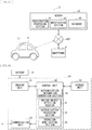
- FIG. 1 illustrates a configuration example of a car sharing system 1 including an imaging apparatus according to a first embodiment. It is to be noted that, although the car sharing system 1 is described as an example, this is not limitative; the present disclosure may be applied to, for example, a system that manages a rental car.
- the car sharing system 1 includes a personal computer 7, a server 10, and a vehicle 8.
- the personal computer 7 and the server 10 are each coupled to Internet NET.
- an imaging apparatus 20 (described later) mounted on the vehicle 8 is coupled to the Internet NET via, for example, a mobile phone network. It is to be noted that this is not limitative; the imaging apparatus 20 may be coupled to the Internet NET via, for example, a wireless LAN (Local Area Network).
- a wireless LAN Local Area Network
- a user U operates, for example, the personal computer 7 to thereby reserve utilization of the vehicle 8.
- the server 10 performs reservation processing on the basis of information (reservation information INF3) on a reservation for utilization supplied from the personal computer 7, and supplies information (authentication information INF2) for authentication of the user U using a facial image of the user U to the imaging apparatus 20 (described later) of the reserved vehicle 8 together with the reservation information INF3.
- the imaging apparatus 20 of the vehicle 8 captures an image of a face of the user U when the user U utilizes the vehicle 8, and performs authentication processing using the authentication information INF2 on the basis of the captured image.
- the vehicle 8 unlocks doors.
- the personal computer 7 is, for example, a computer owned by the user U who uses the car sharing system 1.
- the personal computer 7 accepts an operation of the user U and communicates with the server 10. This allows the user U to perform user registration and to reserve the utilization of the vehicle 8.
- the car sharing system 1 creates an account of the user U, and the user U inputs user information INF1 such as an address and a name, and registers the facial image of the user U.
- the personal computer 7 supplies the user information INF1 and the facial image of the user U to the server 10.
- the user U reserves the utilization of the vehicle 8
- the user U inputs the reservation information INF3 such as a location, a vehicle type, and time for utilization.
- the personal computer 7 supplies the reservation information INF3 to the server 10.
- the personal computer 7 is used in this example, this is not limitative; alternatively, for example, a smartphone or a tablet terminal may be used.
- the server 10 is an apparatus managed by a business operator who operates the car sharing system 1, for example.
- the server 10 includes a registration processing section 11, a reservation processing section 12, and a database 13.
- the registration processing section 11 performs registration processing for registration of the user U on the basis of an instruction from the personal computer 7. Specifically, the registration processing section 11 creates an account of the user U on the basis of an instruction from the personal computer 7. Then, the registration processing section 11 generates the authentication information INF2 including various feature amounts relating to the facial image of the user U on the basis of the facial image of the user U supplied from the personal computer 7. Then, the registration processing section 11 registers, in the database 13, the user information INF1 supplied from the personal computer 7 and the generated authentication information INF2, in association with the account of the user U.
- the reservation processing section 12 performs reservation processing of the vehicle 8 on the basis of the reservation information INF3 supplied from the personal computer 7. In addition, the reservation processing section 12 registers, in the database 13, the reservation information INF3 relating to the reservation processing, in association with the account of the user U.
- the database 13 stores the user information INF1, the authentication information INF2, and the reservation information INF3, in association with the account of the user U.
- This configuration causes the server 10 to accept a reservation for utilization of the vehicle 8. Then, the server 10 supplies the authentication information INF2 and the reservation information INF3 to the imaging apparatus 20 (described later) of the reserved vehicle 8.
- the vehicle 8 is a vehicle managed by a business operator who operates the car sharing system 1, for example.
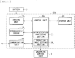
- FIG. 2 illustrates a configuration example of the imaging apparatus 20 mounted on the vehicle 8.
- the imaging apparatus 20 includes an imaging unit 21, a communication unit 22, a storage unit 23, and a control unit 30.
- the imaging unit 21 captures images of surroundings of the vehicle 8, and is configured by using, for example, a CIS (CMOS Image Sensor).
- the imaging unit 21 may capture a color image or a monochrome image.
- the imaging unit 21 is mounted, for example, in a vehicle interior of the vehicle 8, and is so disposed as to capture an image in the front direction of the vehicle 8 as illustrated in FIG. 1 . It is to be noted that this is not limitative; alternatively, for example, the imaging unit 21 may be mounted outside the vehicle 8, or may be so disposed as to capture an image in the rear direction or the lateral direction of the vehicle 8.
- the imaging unit 21 acquires a facial image of the user U by capturing an image of the user U who has approached the vehicle 8, for example.
- the imaging unit 21 has two operation modes M (operation modes M1 and M2).
- the operation mode M1 allows for acquisition of an image having low resolution (low-resolution image PIC1).
- the operation mode M1 is, for example, a mode in which a portion of a plurality of imaging pixels included in the imaging unit 21 is thinned out and operated; an operation of the imaging apparatus 20 in the operation mode M1 makes it possible to reduce power consumption. It is to be noted that this is not limitative; in the operation mode M1, a plurality of imaging pixels may be combined and operated to thereby acquire the low-resolution image PIC1.
- the imaging apparatus 20 performs moving object detection on the basis of the low-resolution image PIC1.
- the operation mode M2 allows for acquisition of an image having high resolution (high-resolution image PIC2).
- the operation mode M2 is, for example, a mode in which all of the plurality of imaging pixels included in the imaging unit 21 are operated.
- the imaging apparatus 20 performs authentication processing on the basis of the high-resolution image PIC2.
- the communication unit 22 communicates with the server 10 via a mobile phone network.
- the communication unit 22 receives, for example, the authentication information INF2 and the reservation information INF3 that are supplied from the server 10.
- the storage unit 23 stores the authentication information INF2 and the reservation information INF3 that are supplied from the server 10.
- the control unit 30 controls an operation of the imaging apparatus 20.
- the control unit 30 is configured by using, for example, CPU (Central Processing Unit), RAM (Random Access Memory), and the like.
- the control unit 30 includes a moving object detection section 31, an authentication processing section 32, and an operation mode setting section 33.
- the moving object detection section 31 detects presence or absence of a moving object on the basis of the low-resolution image PIC1 to thereby perform moving object detection.
- the authentication processing section 32 performs authentication processing by utilizing the authentication information INF2 on the basis of the high-resolution image PIC2.
- the operation mode setting section 33 sets the operation mode M of the imaging unit 21.
- the control unit 30 also has a function of instructing an unlocking control unit 6 (described later) to unlock doors of the vehicle 8 in a case where the authentication processing performed in the authentication processing section 32 is successful.
- the vehicle 8 includes a battery 5 and the unlocking control unit 6, in addition to the imaging apparatus 20.
- the battery 5 is a so-called car battery that supplies electric power to the imaging apparatus 20 and various electronic apparatuses of the vehicle 8.
- the unlocking control unit 6 controls unlocking and locking of the doors of the vehicle 8.
- the unlocking control unit 6 is configured by using ECU (Engine Control Unit) that controls operations of various apparatuses of the vehicle 8, such as an engine and an air-conditioning equipment.
- ECU Engine Control Unit
- This configuration allows the imaging unit 21 to first operate in the operation mode M1 to thereby acquire the low-resolution image PIC1. Then, the moving object detection section 31 performs moving object detection on the basis of the low-resolution image PIC1. In a case where a moving object is detected, the imaging unit 21 operates in the operation mode M2 to thereby acquire the high-resolution image PIC2. Then, the authentication processing section 32 performs authentication processing by utilizing the authentication information INF2 on the basis of the high-resolution image PIC2. In a case where the authentication processing is successful, the control unit 30 instructs the unlocking control unit 6 to unlock the doors of the vehicle 8.
- the car sharing system 1 corresponds to a specific example of a "vehicle utilization system” in the present disclosure.
- the imaging unit 21 corresponds to a specific example of an “imaging unit” in the present disclosure.
- the operation mode M1 corresponds to a specific example of a "first operation mode” in the present disclosure.
- the operation mode M2 corresponds to a specific example of a “second operation mode” in the present disclosure.
- the high-resolution image PIC2 corresponds to a specific example of a "captured image” in the present disclosure.
- the operation mode setting section 33 corresponds to a specific example of an "operation mode setting section” in the present disclosure.
- the moving object detection section 31 corresponds to a specific example of a “detection processing section” in the present disclosure.
- the server 10 corresponds to a specific example of a "second apparatus” in the present disclosure.
- the registration processing section 11 of the server 10 performs registration processing on the basis of an instruction from the personal computer 7. Specifically, the registration processing section 11 creates an account of the user U on the basis of the instruction from the personal computer 7. Then, the registration processing section 11 generates the authentication information INF2 including various feature amounts relating to the facial image of the user U on the basis of the facial image of the user U supplied from the personal computer 7. Then, the registration processing section 11 registers, in the database 13, the user information INF1 and the authentication information INF2, in association with the account of the user U.
- the reservation processing section 12 performs reservation processing of the vehicle 8 on the basis of the reservation information INF3 supplied from the personal computer 7. Then, the reservation processing section 12 registers, in the database 13, the reservation information INF3 relating to the reservation processing, in association with the account of the user U. Then, the server 10 supplies the authentication information INF2 and the reservation information INF3 to the imaging apparatus 20 of the reserved vehicle 8.
- the communication unit 22 of the imaging apparatus 20 receives the authentication information INF2 and the reservation information INF3 that are supplied from the server 10, and the storage unit 23 stores the authentication information INF2 and the reservation information INF3.
- the imaging unit 21 first operates in the operation mode M1 to thereby acquire the low-resolution image PIC1.
- the moving object detection section 31 performs moving object detection on the basis of the low-resolution image PIC1.
- the imaging unit 21 operates in the operation mode M2 to thereby acquire the high-resolution image PIC2.
- the authentication processing section 32 performs authentication processing by utilizing the authentication information INF2 on the basis of the high-resolution image PIC2.
- the control unit 30 instructs the unlocking control unit 6 to unlock the doors of the vehicle 8.
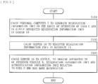
- FIG. 3 illustrates an operation example of the car sharing system 1 when the user U reserves utilization of the vehicle 8.
- the personal computer 7 generates the reservation information INF3 on the basis of an operation of the user U, and supplies the generated reservation information INF3 to the server 10 (step S101).
- the reservation processing section 12 of the server 10 registers the received reservation information INF3 in the database 13, in association with the account of the user U (step S102).
- the server 10 supplies, to the imaging apparatus 20 of the reserved vehicle 8, the reservation information INF3 and the authentication information INF2 relating to the user U who has reserved the utilization of the vehicle 8 (step S103).
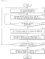
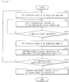
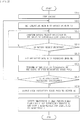
- FIG. 4 illustrates an operation example of the car sharing system 1 when the user U who has reserved utilization of the vehicle 8 starts the utilization of the vehicle 8.
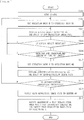
- the operation mode setting section 33 sets the operation mode M of the imaging unit 21 to the operation mode M1 (step S111). This allows the imaging unit 21 to start acquiring the low-resolution image PIC1. It is to be noted that the operation mode setting section 33 may set the operation mode M to the operation mode M1 when a previous user of the vehicle 8 has parked the vehicle 8 at a station of the car sharing system 1, or may set the operation mode M to the operation mode M1 at a starting time of the utilization indicated by the reservation information INF3.
- the moving object detection section 31 performs moving object detection on the basis of the low-resolution image PIC1 (step S112).
- the moving object detection section 31 checks whether or not a moving object is detected (step S113). When no moving object is detected ("N" in step S113), the flow returns to step S112, and these steps S112 and S113 are repeated until a moving object is detected. Specifically, these steps S112 and S113 are repeated, for example, until the user U approaches the vehicle 8 in a period of time corresponding to the reservation information INF3 and the moving object detection section 31 detects the user U as a moving object.
- the operation mode setting section 33 sets the operation mode M of the imaging unit 21 to the operation mode M2 (step S114). This allows the imaging unit 21 to acquire the high-resolution image PIC2.
- the high-resolution image PIC2 includes, for example, a facial image of the user U.
- the authentication processing section 32 performs authentication processing by utilizing the authentication information INF2 stored in the storage unit 23 on the basis of the high-resolution image PIC2 (step S115). That is, the high-resolution image PIC2 includes, for example, the facial image of the user U, and thus the authentication processing section 32 performs the authentication processing by utilizing the authentication information INF2 on the basis of the high-resolution image PIC2.
- the authentication processing section 32 checks whether or not the authentication processing is successful (step S116). In a case where the authentication processing has failed ("N" in step S116), the flow returns to step S111, and the operation mode setting section 33 sets the operation mode M to the operation mode M1. That is, in this case, for example, a stranger having no relation with the user U who has reserved the utilization happens to approach the vehicle 8 and the operation mode setting section 33 has set the operation mode M to the operation mode M2; therefore, the operation mode setting section 33 returns the operation mode M to the operation mode M1.
- step S116 In a case where the authentication processing is successful in step S116 ("Y" in step S116), the control unit 30 instructs the unlocking control unit 6 to unlock doors of the vehicle 8 (step S117).
- the authentication processing is performed on the basis of a captured image (the high-resolution image PIC2), and when the authentication processing is successful, the doors of the vehicle 8 are unlocked, thus making it possible to enhance convenience of the user U. That is, for example, in a case where a reader/writer of near field communication (NFC; Near Field Communication) is mounted on a vehicle and the vehicle is utilized by waving a member card of the car sharing system over the reader/writer, for example, leaving the member card behind at home makes the car sharing system unavailable, which is inconvenient. In addition, for example, losing a member card leads to a possibility that the member card may be utilized illegally by a person who has picked up the member card. Meanwhile, in the car sharing system 1, the authentication processing is performed on the basis of a captured image, and thus only capturing an image of the user U enables the user U to utilize the car sharing system 1, thus making it possible to enhance convenience of the user.
- NFC Near Field Communication
- the imaging apparatus 20 is configured by using the imaging unit 21 having the operation modes M1 and M2, thus making it possible to reduce power consumption. That is, the high-resolution image PIC2 needs to be used to perform the authenticating process; however, in a case where the imaging unit 21 acquires the high-resolution image PIC2 constantly, there is a possibility that the power consumption may increase. As a result, there is a possibility, in the vehicle 8, that a battery level in the battery 5 may be lowered. Meanwhile, in the car sharing system 1, first setting the operation mode M of the imaging unit 21 to the operation mode M1 allows the low-resolution image PIC1 to be acquired.
- the operation mode M of the imaging unit 21 is set to the operation mode M2, thereby allowing the high-resolution image PIC2 to be acquired. This enables the car sharing system 1 to effectively reduce the power consumption.
- the authentication processing is configured to be performed on the basis of a result of imaging performed by the imaging unit 21, thus making it possible to suppress introduction costs. That is, in recent years, a vehicle has been increasingly equipped with a drive recorder and an advanced driver assistance system (ADAS; advanced driver assistance system). The vehicle with the drive recorder and the ADAS being introduced is mounted with an imaging unit. Therefore, configuring the imaging apparatus 20 by using the imaging unit that has already been mounted in this manner makes it possible to suppress the introduction costs.
- ADAS advanced driver assistance system
- the authentication processing is performed on the basis of a captured image, and the doors of the vehicle are unlocked when the authentication processing is successful, thus making it possible to enhance convenience of the user.
- the imaging apparatus is configured by using the imaging unit having the operation modes M1 and M2, thus making it possible to reduce the power consumption.
- the authentication processing is configured to be performed on the basis of a result of imaging performed by the imaging unit, thus making it possible to suppress the introduction costs.
- the imaging apparatus 20 performs the authentication processing, but this is not limitative; alternatively, for example, a server may perform the authentication processing.
- a server may perform the authentication processing.
- the car sharing system 1A according to the present modification example is described in detail.
- FIG. 5 illustrates a configuration example of the car sharing system 1A.
- the car sharing system 1A includes a server 10A and a vehicle 8A.
- the server 10A includes an authentication processing section 14A.
- the authentication processing section 14A performs authentication processing using the authentication information INF2 stored in the database 13 on the basis of the high-resolution image PIC2 supplied from an imaging apparatus 20A (described later) of the vehicle 8A.
- the server 10A also has a function of notifying the imaging apparatus 20A (described later) of the vehicle 8A of a processing result of the authentication processing performed by the authentication processing section 14A.
- the server 10A corresponds to a specific example of a "third apparatus" in the present disclosure.
- FIG. 6 illustrates a configuration example of the imaging apparatus 20A mounted on the vehicle 8A.
- the imaging apparatus 20A includes a control unit 30A.
- the control unit 30A includes the moving object detection section 31 and the operation mode setting section 33. That is, the control unit 30A omits the authentication processing section 32 from the control unit 30 according to the foregoing first embodiment.
- the control unit 30A also has functions of supplying, to the server 10A using the communication unit 22, the high-resolution image PIC2 acquired by the imaging unit 21 when the operation mode M of the imaging unit 21 is set to the operation mode M2 and of instructing the unlocking control unit 6 to unlock doors of the vehicle 8A in a case where a notification is received from the server 10A to the effect that authentication processing is successful.
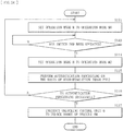
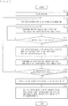
- FIG. 7 illustrates an operation example of the car sharing system 1A when the user U who has reserved utilization of the vehicle 8A starts the utilization of the vehicle 8A.
- the operation mode setting section 33 sets the operation mode M of the imaging unit 21 to the operation mode M1 (step S111). This allows the imaging unit 21 to start acquiring the low-resolution image PIC1.
- the moving object detection section 31 performs moving object detection on the basis of the low-resolution image PIC1 (step S112). Then, the moving object detection section 31 checks whether or not a moving object is detected (step S113). In a case where no moving object is detected ("N" in step S113), the flow returns to step S112. In a case where a moving object is detected ("Y" in step S113), the operation mode setting section 33 sets the operation mode M of the imaging unit 21 to the operation mode M2 (step S114). This allows the imaging unit 21 to acquire the high-resolution image PIC2.
- the communication unit 22 of the imaging apparatus 20A supplies the high-resolution image PIC2 to the server 10A (step S121).
- the authentication processing section 14A of the server 10A performs authentication processing by utilizing the authentication information INF2 stored in the database 13 on the basis of the high-resolution image PIC2 supplied from the imaging apparatus 20A (step S122).
- step S123 the authentication processing section 14A checks whether or not the authentication processing is successful (step S123). In a case where the authentication processing has failed ("N" in step S123), the server 10A notifies the imaging apparatus 20A that the authentication processing has failed (step S124). The communication unit 22 of the imaging apparatus 20A receives this notification. Then, the flow returns to step Sill.
- step S123 the server 10A notifies the imaging apparatus 20A that the authentication processing is successful (step S125).
- the communication unit 22 of the imaging apparatus 20A receives this notification.
- control unit 30A instructs the unlocking control unit 6 to unlock the doors of the vehicle 8A (step S116). This completes the flow.
- one imaging unit 21 is provided, but this is not limitative.
- one imaging unit 21B1 may be provided similarly to the above embodiment.
- the imaging unit 21B is so disposed as to capture an image in the front direction of the vehicle 8B1.
- two imaging units 21B1 and 21B2 may be provided.
- the imaging unit 21B2 is so disposed as to capture an image in the right direction of the vehicle 8B2. That is, in the vehicle 8B2, the driver's seat is on right side, and the user U approaches the right side of the vehicle 8B2; thus, the imaging unit 21B2 captures an image in the right direction of the vehicle 8B2.
- the imaging unit 21B3 is so disposed as to capture an image in the left front direction of the vehicle 8B3; the imaging unit 21B4 is so disposed as to capture an image in the right front direction of the vehicle 8B3; the imaging unit 21B5 is so disposed as to capture an image in the left rear direction of the vehicle 8B3; and the imaging unit 21B6 is so disposed as to capture an image in the right rear direction of the vehicle 8B3.
- the five imaging units 21B1 and 21B3 to 21B6 configure, for example, a parking camera system.
- each of these five imaging units 21B1 and 21B3 to 21B6 has the two operation modes M (the operation modes M1 and M2).
- An operation mode setting section 33B according to the present modification example may set the operation modes M of these five imaging units 21B1 and 21B3 to 21B6 collectively.
- the operation mode setting section 33B is able to set the operation mode M of each of the five imaging units 21B1 and 21B3 to 21B6 to the operation mode M2.
- the operation mode setting section 33B may individually set the operation modes M of these five imaging units 21B1 and 21B3 to 21B6. Specifically, in a case where the five imaging units 21B1 and 21B3 to 21B6 operate in the operation mode M1, when the moving object detection section 31B detects a moving object on the basis of, for example, the low-resolution image PIC1 acquired by the imaging unit 21B4, the operation mode setting section 33B is able to set the operation mode M of the imaging unit 21B4 to the operation mode M2.
- the imaging unit 21 operates all of the plurality of imaging pixels included in the imaging unit 21 in the operation mode M2 that acquires the high-resolution image PIC2, but this is not limitative; alternatively, for example, a portion of the plurality of imaging pixels included in the imaging unit 21 may be operated.
- a car sharing system 1C according to the present modification example is described in detail.
- the car sharing system 1C includes a vehicle 8C.
- the vehicle 8C includes an imaging apparatus 20C.
- the imaging apparatus 20C includes an imaging unit 21C and a control unit 30C.
- FIG. 9 illustrates an example of an imaging region 100 in the imaging unit 21C.
- the imaging region 100 of the imaging unit 21C is divided into a plurality of regions 101. Although not illustrated, a plurality of imaging pixels are arranged side by side in each of the plurality of regions 101.
- the imaging unit 21C is configured to be able to perform an imaging operation using the regions 101 as a unit.
- the imaging unit 21C has two operation modes M (operation modes M1 and M3).
- the operation mode M3 allows for acquisition of an image having high resolution (a high-resolution image PIC3), and is a mode in which an imaging operation is performed using the regions 101 as a unit. That is, the operation mode M3 is a so-called ROI (Region of Interest) mode that allows for operations of only imaging pixels of one or a plurality of regions 101, of the imaging region 100, where the imaging operation is desired to be performed.
- ROI Region of Interest
- the control unit 30C includes an operation mode setting section 33C.
- the operation mode setting section 33C sets the operation mode M of the imaging unit 21C.
- the operation mode setting section 33C selectively operates one or a plurality of regions 101, of the imaging region 100, where a moving object has been detected in the moving object detection.
- FIG. 10 illustrates an operation example of the car sharing system 1C when the user U who has reserved utilization of the vehicle 8C starts the utilization of the vehicle 8C.
- the operation mode setting section 33C sets the operation mode M of the imaging unit 21 to the operation mode M1 (step S111). This allows the imaging unit 21C to start acquiring the low-resolution image PIC1.
- the moving object detection section 31 performs moving object detection on the basis of the low-resolution image PIC1 (step S112). Then, the moving object detection section 31 checks whether or not a moving object is detected (step S113). In a case where no moving object is detected ("N" in step S113), the flow returns to step S112.
- the operation mode setting section 33C sets the operation mode M of the imaging unit 21C to the operation mode M3, and sets regions 101 to be operated, out of the imaging region 100 (step S134). At this time, the operation mode setting section 33C sets, as the regions 101 to be operated, one or a plurality of regions 101 where a moving object has been detected in the moving object detection, out of the imaging region 100. This allows the imaging unit 21C to acquire the high-resolution image PIC3.
- the authentication processing section 32 performs authentication processing by utilizing the authentication information INF2 stored in the storage unit 23 on the basis of the high-resolution image PIC3 (step S135).
- step S136 the authentication processing section 32 checks whether or not the authentication processing is successful (step S136). In a case where the authentication processing has failed ("N" in step S136), the flow returns to step S111. In a case where the authentication processing is successful ("Y" in step S136), the control unit 30C instructs the unlocking control unit 6 to unlock doors of the vehicle 8C (step S117). This completes the flow.
- the car sharing system 1C in the operation mode M3 that acquires the high-resolution image PIC3, one or a plurality of regions 101, of the imaging region 100, where a moving object has been detected in the moving object detection is operated.
- This enables the car sharing system 1C, for example, to operate only the regions 101 including the facial image of the user while stopping the operation of other regions 101, thus making it possible to effectively reduce the power consumption.
- the imaging unit 21C has the two operation modes M1 and M3, but this is not limitative; for example, the imaging unit 21C may further have an operation mode M2 that acquires the high-resolution image PIC2.
- the operation may be performed in the operation mode M2 as necessary after the operation is performed in the operation mode M3.
- the imaging apparatus 20C may set the operation mode M to the operation mode M2 and operate all the regions 101.
- the imaging unit 21 sets the operation mode M to the operation mode M2 in a case where a moving object is detected in the imaging region 100 of the imaging unit 21, but this is not limitative.
- the operation mode M may be set to the operation mode M2.
- a car sharing system 1D according to the present modification example is described in detail.
- the car sharing system 1D includes a vehicle 8D.
- the vehicle 8D includes an imaging apparatus 20D.
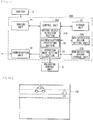
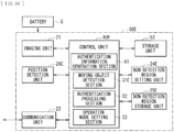
- FIG. 11 illustrates a configuration example of the imaging apparatus 20D.
- the imaging apparatus 20D includes a non-detection region setting unit 24D, a non-detection region storage unit 25D, and a control unit 30D.
- the non-detection region setting unit 24D sets a non-detection region 102 on the basis of, for example, an operation by a person in charge of a business operator who operates the car sharing system 1D.
- the non-detection region 102 is a region, of the imaging region 100, excluded from a target region of the moving object detection. That is, as described later, the imaging apparatus 20D checks whether or not a moving object is detected in a region, of the imaging region 100, other than the non-detection region 102.
- the non-detection region storage unit 25D stores the non-detection region 102 set by the non-detection region setting unit 24D.
- FIG. 12 illustrates an example of the non-detection region 102.
- a road is seen in a captured image of the imaging unit 21. A vehicle and a person pass through this road.
- the non-detection region setting unit 24D sets a region including this road as the non-detection region 102. That is, in a case where the non-detection region 102 is not set, there is a possibility that a moving object may be detected each time a vehicle or a person passes through a road near the vehicle 8D; therefore, in this example, a region including this road is set as the non-detection region 102.
- the control unit 30D includes a moving object detection section 31D.
- the moving object detection section 31D performs moving object detection on the basis of the low-resolution image PIC1.
- the moving object detection section 31D has a function of checking whether or not a moving object is detected in a region other than the non-detection region 102.
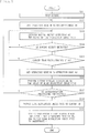
- FIG. 13 illustrates an operation example of the car sharing system 1D when the user U who has reserved utilization of the vehicle 8D starts the utilization of the vehicle 8D.
- the operation mode setting section 33 sets the operation mode M of the imaging unit 21 to the operation mode M1 (step S111). This allows the imaging unit 21 to start acquiring the low-resolution image PIC1.
- the moving object detection section 31D performs moving object detection on the basis of the low-resolution image PIC1 (step S112). Then, the moving object detection section 31D checks whether or not a moving object is detected (step S113). In a case where no moving object is detected ("N" in step S113), the flow returns to step S112.
- step S113 In a case where a moving object is detected in step S113 ("Y" in step S113), the moving object detection section 31D checks whether or not a moving object is detected in a region other than the non-detection region 102 (step S143). In a case where no moving object is detected in the region other than the non-detection region 102 ("N" in step S143), the flow returns to step S112.
- the operation mode setting section 33 sets the operation mode M of the imaging unit 21 to the operation mode M2 (step S114). This allows the imaging unit 21 to acquire the high-resolution image PIC2. Then, the authentication processing section 32 performs authentication processing by utilizing the authentication information INF2 stored in the storage unit 23 on the basis of the high-resolution image PIC2 (step S115).
- step S116 the authentication processing section 32 checks whether or not the authentication processing is successful (step S116). In a case where the authentication processing has failed ("N" in step S116), the flow returns to step Sill. In a case where the authentication processing is successful ("Y" in step S116), the control unit 30D instructs the unlocking control unit 6 to unlock doors of the vehicle 8D (step S117). This completes the flow.
- the operation mode M is set to the operation mode M2 in a case where a moving object is detected in a region other than the non-detection region 102. This makes it possible to reduce a possibility that the operation mode M may be set to the operation mode M2 each time a vehicle or a person passes through a road near the vehicle 8D, for example, thus making it possible to effectively reduce the power consumption.
- the non-detection region setting unit 24D is able to set the non-detection region 102, for example, on the basis of the operation of a person in charge of the business operator who operates the car sharing system 1D. Specifically, for example, the person in charge is able to set the non-detection region 102 while confirming a captured image taken by the imaging unit 21 when the vehicle 8D is parked in a station of the car sharing system 1D. For example, in a case where a location of the station of the car sharing system 1D is changed, the person in charge is able to similarly set the non-detection region 102 again.
- a plurality of non-detection regions 102 may be set in advance, and one of the plurality of non-detection regions 102 may be selected.
- the imaging apparatus 20E includes a non-detection region setting unit 24E, a non-detection region storage unit 25E, a position detection unit 26E, and a control unit 30E.
- the non-detection region setting unit 24E is able to set the plurality of non-detection regions 102.
- the non-detection region storage unit 25E stores the plurality of non-detection regions 102 set by the non-detection region setting unit 24E.
- the position detection unit 26E detects a position and an orientation of a vehicle 8E mounted with the imaging apparatus 20E, and is configured by using, for example, a GPS (Global Positioning System) receiver, a geomagnetic sensor, or the like.
- the control unit 30E includes a moving object detection section 31E.
- the moving object detection section 31E selects one of the plurality of non-detection regions 102 stored in the non-detection region storage unit 25E on the basis of a result of the detection of the position detection unit 26E, and performs moving object detection on the basis of the low-resolution image PIC1 using the selected non-detection region 102. Accordingly, for example, in a case where there is a plurality of stations of a car sharing system 1E, it is possible to select non-detection regions 102 in accordance with a station where the vehicle 8E is parked.
- the non-detection region setting unit 24D sets the non-detection region 102 on the basis of the operation of a person in charge, but this is not limitative.
- the non-detection region setting unit may automatically set the non-detection region 102.
- the imaging unit 21 may perform an imaging operation for a predetermined length of time, and a non-detection region setting unit 24F according to the present modification example may set, as the non-detection region 102, a region where a moving object has been detected in the imaging region 100.
- the non-detection region setting unit 24F may set the non-detection region 102 using, for example, a machine learning method.
- the non-detection region setting unit 24F may detect a road by performing image recognition processing on the basis of a captured image to set the non-detection region 102 on the basis of a result of the detection, or may acquire map data via, for example, the Internet NET to set the non-detection region 102 by utilizing the map data.
- the imaging unit 21 sets the operation mode M to the operation mode M2 in a case where a moving object is detected in the imaging region 100 of the imaging unit 21, but this is not limitative.
- the operation mode M may be set to the operation mode M2 on the basis of, for example, a size of an image of a moving object detected by the moving object detection or a position of the image of the detected moving object.
- the present modification example is described in detail with reference to several examples.
- a car sharing system 1G includes a vehicle 8G.
- the vehicle 8G includes an imaging apparatus 20G.
- the imaging apparatus 20G includes a control unit 30G.
- the control unit 30G includes a moving object detection section 31G.
- the moving object detection section 31G performs moving object detection on the basis of the low-resolution image PIC1.
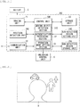
- the moving object detection section 31G also has functions of determining a size of an image of a moving object detected by the moving object detection and of judging whether or not the size is larger than a predetermined size. That is, as illustrated in FIG. 15 , the captured image may include images of various subjects, but in a case where the imaging apparatus 20G performs authentication processing, it is expected that a face of the user U is seen to be large. Therefore, the moving object detection section 31G determines the size of the image of the detected moving object, and judges whether or not the size is larger than the predetermined size.
- FIG. 16 illustrates an operation example of the car sharing system 1G when the user U who has reserved utilization of the vehicle 8G starts the utilization of the vehicle 8G.
- the operation mode setting section 33 sets the operation mode M of the imaging unit 21 to the operation mode M1 (step S111). This allows the imaging unit 21 to start acquiring the low-resolution image PIC1.
- the moving object detection section 31G performs moving object detection on the basis of the low-resolution image PIC1 (step S112). Then, the moving object detection section 31G checks whether or not a moving object is detected (step S113). In a case where no moving object is detected ("N" in step S113), the flow returns to step S112.
- the moving object detection section 31G checks whether or not a size of an image of the detected moving object is larger than a predetermined size (step S153). Specifically, the moving object detection section 31G determines an area of the image of the detected moving object, and checks whether or not the area of the image is larger than a predetermined area. In a case where the size of the image of the detected moving object is not larger than the predetermined size ("N" in step S153), the flow returns to step S112.
- the operation mode setting section 33 sets the operation mode M of the imaging unit 21 to the operation mode M2 (step S114). This allows the imaging unit 21 to acquire the high-resolution image PIC2. Then, the authentication processing section 32 performs authentication processing by utilizing the authentication information INF2 stored in the storage unit 23 on the basis of the high-resolution image PIC2 (step S115).
- step S116 the authentication processing section 32 checks whether or not the authentication processing is successful (step S116). In a case where the authentication processing has failed ("N" in step S116), the flow returns to step Sill. In a case where the authentication processing is successful ("Y" in step S116), the control unit 30G instructs the unlocking control unit 6 to unlock doors of the vehicle 8G (step S117). This completes the flow.
- the operation mode M is set to the operation mode M2 in a case where the size of the image of the moving object detected by the moving object detection section 31G is larger than a predetermined size. Accordingly, for example, even in a case where a person or an animal happens to be close to the vehicle 8G, the size of the image of the person or the animal is small, and thus the operation mode setting section 33 does not change the operation mode M. As a result, it is possible for the car sharing system 1G to reduce a possibility that the operation mode M may be set to the operation mode M2 each time a person or an animal passes near the vehicle 8G, thus making it possible to effectively reduce the power consumption.
- the car sharing system 1H includes a vehicle 8H.
- the vehicle 8H includes an imaging apparatus 20H.
- the imaging apparatus 20H includes a control unit 30H.
- the control unit 30H includes a moving object detection section 31H.
- the moving object detection section 31H performs moving object detection on the basis of the low-resolution image PIC1.
- the moving object detection section 31H also has a function of judging whether or not an image of the moving object detected by the moving object detection is in contact with an edge of the low-resolution image PIC1. That is, as illustrated in FIG.
- the captured image may include images of various subjects; in a case where the imaging apparatus 20H performs authentication processing, it is expected that a face of the user U is seen to be large. In this case, a whole-body image of the user U does not fit in the captured image, and thus the image of the user U comes into contact with an edge of the captured image. Hence, the moving object detection section 31H judges whether or not the image of the detected moving object (the user U in this example) is in contact with an edge of the low-resolution image PIC1.
- FIG. 17 illustrates an operation example of the car sharing system 1H when the user U who has reserved utilization of the vehicle 8H starts the utilization of the vehicle 8H.
- step S153 in the flowchart ( FIG. 16 ) of the car sharing system 1G is replaced with step S163.
- step S113 In a case where a moving object is detected in step S113 ("Y" in step S113), the moving object detection section 31H checks whether or not the image of the detected moving object is in contact with an edge of the low-resolution image PIC1 (step S163). In a case where the image of the detected moving object is not in contact with an edge of the low-resolution image PIC1 ("N" in step S163), the flow returns to step S112.
- the operation mode setting section 33 sets the operation mode M of the imaging unit 21 to the operation mode M2 (step S114).
- the operation mode M is set to the operation mode M2 in a case where the image of the moving object detected by the moving object detection section 31H is in contact with an edge of the low-resolution image PIC1. This makes it possible to reduce a possibility that the operation mode M may be set to the operation mode M2 each time a person or an animal passes near the vehicle 8H, thus making it possible to effectively reduce the power consumption.
- these car sharing systems 1G and 1H may be combined.
- the operation mode M may be set to the operation mode M2. Also in this case, it is possible to effectively reduce the power consumption.
- the registration processing section 11 of the server 10 generates the authentication information INF2 on the basis of the facial image of the user U, but this is not limitative; alternatively, for example, the imaging apparatus may generate the authentication information INF2 on the basis of the facial image of the user U.
- the imaging apparatus may generate the authentication information INF2 on the basis of the facial image of the user U.
- FIG. 19 illustrates a configuration example of the car sharing system 1K.
- the car sharing system 1K includes a server 10K and a vehicle 8K.
- the server 10K includes a registration processing section 11K and a database 13K.
- the registration processing section 11K performs registration processing for registration of a user on the basis of an instruction from the personal computer 7. Specifically, the registration processing section 11 creates an account of the user U on the basis of an instruction from the personal computer 7. Then, the registration processing section 11K registers the user information INF1 and the facial image of the user U in the database 13K, in association with the account of the user U.
- the database 13K stores the user information INF1, the facial image of the user U, and the reservation information INF3, in association with the account of the user U.
- the server 10K accepts a reservation for utilization of the vehicle 8K. Further, the server 10K supplies the facial image of the user U and the reservation information INF3 to an imaging apparatus 20K (described later) of the reserved vehicle 8K.
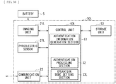
- FIG. 20 illustrates a configuration example of the imaging apparatus 20K mounted on the vehicle 8K.
- the imaging apparatus 20K includes a control unit 30K.
- the control unit 30K includes an authentication information generation section 34K.
- the authentication information generation section 34K generates the authentication information INF2 including various feature amounts relating to the facial image of the user U on the basis of the facial image of the user U supplied from the server 10K.
- the storage unit 23 stores the authentication information INF2 generated by the authentication information generation section 34K and the reservation information INF3 supplied from the server 10K.
- the moving object detection is performed on the basis of the low-resolution image PIC1 acquired by the imaging unit 21, but this is not limitative.
- the present modification example is described in detail with reference to several examples.
- a car sharing system 1L according to the present modification example includes a vehicle 8L.
- the vehicle 8L includes an imaging apparatus 20L.
- FIG. 21 illustrates a configuration example of the imaging apparatus 20L.
- the imaging apparatus 20L includes an imaging unit 21L, a pyroelectric sensor 27L, and a control unit 30L.
- the imaging unit 21L has two operation modes M (operation modes M0 and M2).
- the operation mode M0 is a mode that stops an imaging operation.
- the imaging apparatus 20L is able to reduce power consumption by setting the operation mode M of the imaging unit 21L to the operation mode M0.
- the pyroelectric sensor 27L is, for example, an infrared sensor, and detects a moving object (e.g., the user U).
- the control unit 30L includes an operation mode setting section 33L.
- the operation mode setting section 33L sets the operation mode M of the imaging unit 21L. In a case where, for example, the operation mode M of the imaging unit 21L is the operation mode M0, when the pyroelectric sensor 27L detects a moving object, the operation mode setting section 33L sets the operation mode M to the operation mode M2.
- the pyroelectric sensor 27L corresponds to a specific example of a "sensor" in the present disclosure.
- FIG. 22 illustrates an operation example of the car sharing system 1L when the user U who has reserved utilization of the vehicle 8L starts the utilization of the vehicle 8L.
- the operation mode setting section 33L sets the operation mode M of the imaging unit 21L to the operation mode M0 (step S171). This causes the imaging unit 21L to stop the imaging operation. Then, the pyroelectric sensor 27L performs moving object detection (step S172).
- control unit 30L checks whether or not the pyroelectric sensor 27L has detected a moving object (step S173). In a case where no moving object is detected ("N" in step S173), the flow returns to step S172.
- the operation mode setting section 33L sets the operation mode M of the imaging unit 21L to the operation mode M2 (step S114). This allows the imaging unit 21L to acquire the high-resolution image PIC2. Then, the authentication processing section 32 performs authentication processing by utilizing the authentication information INF2 stored in the storage unit 23 on the basis of the high-resolution image PIC2 (step S115).
- step S116 the authentication processing section 32 checks whether or not the authentication processing is successful (step S116). In a case where the authentication processing has failed ("N" in step S116), the flow returns to step S171. In a case where the authentication processing is successful ("Y" in step S116), the control unit 30L instructs the unlocking control unit 6 to unlock doors of the vehicle 8L (step S117). This completes the flow.
- the imaging apparatus 20 is configured by using the imaging unit 21L having the operation mode M0 that stops the imaging operation and the operation mode M2 that acquires the high-resolution image PIC2, and the operation mode M is set to the operation mode M2 when the pyroelectric sensor 27L detects a moving object, thus making it possible to reduce the power consumption.
- the car sharing system 1M includes a vehicle 8M.
- the vehicle 8M includes an imaging apparatus 20M.
- FIG. 23 illustrates a configuration example of the imaging apparatus 20M.
- the imaging apparatus 20M includes the imaging unit 21L, a switch 28M, and a control unit 30M.
- the switch 28M is operated by the user U, for example.
- the control unit 30M includes an operation mode setting section 33M.
- the operation mode setting section 33M sets the operation mode M of the imaging unit 21L. In a case where, for example, the operation mode M of the imaging unit 21L is the operation mode M0, when the switch 28M is operated, the operation mode setting section 33M sets the operation mode M to the operation mode M2.
- FIG. 24 illustrates an operation example of the car sharing system 1M when the user U who has reserved utilization of the vehicle 8M starts the utilization of the vehicle 8M.
- the operation mode setting section 33M sets the operation mode M of the imaging unit 21L to the operation mode M0 (step S171). This causes the imaging unit 21L to stop the imaging operation.
- step S183 the control unit 30M checks whether or not the switch 28M has been operated (step S183). In a case where the switch 28M has not been operated ("N" in step S183), the flow returns to step S183, and this step S183 is repeated until the switch 28M is operated. Specifically, for example, this step S183 is repeated until the user U approaches the vehicle 8M and operates the switch 28M at the time corresponding to the reservation information INF3.
- the operation mode setting section 33M sets the operation mode M of the imaging unit 21L to the operation mode M2 (step S114). This allows the imaging unit 21L to acquire the high-resolution image PIC2. Then, the authentication processing section 32 performs authentication processing by utilizing the authentication information INF2 stored in the storage unit 23 on the basis of the high-resolution image PIC2 (step S115).
- step S116 the authentication processing section 32 checks whether or not the authentication processing is successful (step S116). In a case where the authentication processing has failed ("N" in step S116), the flow returns to step S171. In a case where the authentication processing is successful ("Y" in step S116), the control unit 30M instructs the unlocking control unit 6 to unlock doors of the vehicle 8M (step S117). This completes the flow.
- the imaging apparatus 20 is configured by using the imaging unit 21L having the operation mode M0 that stops the imaging operation and the operation mode M2 that acquires the high-resolution image PIC2, and the operation mode M is set to the operation mode M2 when the user U operates the switch 28M, thus making it possible to reduce the power consumption.
- a vehicle monitoring system 2 including an imaging apparatus according to a second embodiment. It is to be noted that components substantially the same as those of the imaging apparatus 20 of the car sharing system 1 according to the foregoing first embodiment are denoted by the same reference numerals, and descriptions thereof are omitted where appropriate.
- FIG. 25 illustrates a configuration example of the vehicle monitoring system 2.
- the vehicle monitoring system 2 includes a vehicle 9, a server 40, and a smartphone 4.
- the server 40 is coupled to the Internet NET.
- the smartphone 4 and an imaging apparatus 50 (described later) mounted on the vehicle 9 are coupled to the Internet NET via a mobile phone network, for example.
- the imaging apparatus 50 (described later) of the vehicle 9 captures an image of a person who has approached the vehicle 9, and performs authentication processing by using the authentication information INF2 on the basis of the captured image. Then, in a case where the authentication processing has failed, the imaging apparatus 50 supplies the captured image to the server 40. Then, the server 40 notifies the smartphone 4 that a person other than the registered user U has approached the vehicle 9, and supplies the captured image to the smartphone 4.
- the vehicle 9 is, for example, a vehicle owned by the user U who utilizes the vehicle monitoring system 2.
- FIG. 26 illustrates a configuration example of the imaging apparatus 50 mounted on the vehicle 9.
- the imaging apparatus 50 includes the imaging unit 21, the communication unit 22, a control unit 60, and a storage unit 53.
- the control unit 60 includes an authentication information generation section 61, the moving object detection section 31, the authentication processing section 32, and the operation mode setting section 33.
- the authentication information generation section 61 generates the authentication information INF2 including various feature amounts relating to a facial image of the user U on the basis of the facial image of the user U captured by the imaging unit 21. That is, the user U causes the imaging unit 21 to capture an own image of the user U prior to utilization of the vehicle monitoring system 2. The authentication information generation section 61 generates the authentication information INF2 on the basis of the facial image of the user U captured in this manner.
- the moving object detection section 31 performs moving object detection by detecting presence or absence of a moving object on the basis of the low-resolution image PIC1.
- the authentication processing section 32 performs authentication processing by utilizing the authentication information INF2 on the basis of the high-resolution image PIC2.
- the operation mode setting section 33 sets the operation mode M of the imaging unit 21.
- control unit 60 also has a function of instructing the communication unit 22 to supply the high-resolution image PIC2 to the server 40 in a case where the authentication processing performed by the authentication processing section 32 has failed.
- the storage unit 53 stores the authentication information INF2 generated by the authentication information generation section 61. It is to be noted that, in this example, the authentication information INF2 on one user U is stored, but this is not limitative; a plurality of pieces of authentication information INF2 corresponding, respectively, to a plurality of users U who may utilize the vehicle 9 may be stored.
- the imaging unit 21 operates in the operation mode M1 to thereby acquire the low-resolution image PIC1.
- the moving object detection section 31 performs moving object detection on the basis of the low-resolution image PIC1.
- the imaging unit 21 operates in the operation mode M2 to thereby acquire the high-resolution image PIC2.
- the authentication processing section 32 performs authentication processing by utilizing the authentication information INF2 on the basis of the high-resolution image PIC2.
- the communication unit 22 supplies the high-resolution image PIC2 to the server 40.
- the smartphone 4 ( FIG. 25 ) is, for example, a multifunctional mobile phone owned by the user U who utilizes the vehicle monitoring system 2.
- the smartphone 4 accepts an operation of the user U and communicates with the server 40.
- the vehicle monitoring system 2 creates an account of the user U, and the user U inputs the user information INF1 such as an address and a name.
- the smartphone 4 supplies the user information INF1 to the server 40.
- the smartphone 4 displays such a notification as well as the high-resolution image PIC2 on a display unit.
- the server 40 is, for example, an apparatus managed by a business operator who operates the vehicle monitoring system 2.
- the server 40 includes a registration processing section 41, a notification section 42, and a database 43.
- the registration processing section 41 performs registration processing for registration of a user on the basis of an instruction from the smartphone 4. Specifically, the registration processing section 41 creates an account of the user U on the basis of an instruction from the smartphone 4. Then, the registration processing section 41 registers the user information INF1 supplied from the smartphone 4 in the database 43, in association with the account of the user U.
- the notification section 42 notifies the smartphone 4 that a person other than the registered user U has approached the vehicle 9, and supplies the high-resolution image PIC2 to the smartphone 4.
- the database 43 stores the user information INF1, the high-resolution image PIC2, and history of the notification, in association with the account of the user U.
- the vehicle monitoring system 2 corresponds to a specific example of a “vehicle monitoring system” in the present disclosure.
- the server 40 corresponds to a specific example of a "first apparatus” in the present disclosure.
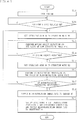
- FIG. 27 illustrates an operation example of the vehicle monitoring system 2 when the user U stops the vehicle 9 in a parking lot.
- the vehicle 9 stops the engine on the basis of an operation of the user U (step S211).
- the operation mode setting section 33 sets the operation mode M of the imaging unit 21 to the operation mode M1 (step S212). This allows the imaging unit 21 to start acquiring the low-resolution image PIC1. Then, the moving object detection section 31 performs moving object detection on the basis of the low-resolution image PIC1 (step S213).
- the moving object detection section 31 checks whether or not a moving object is detected (step S214). In a case where no moving object is detected ("N" in step S214), the flow returns to step S213, and these steps S213 and S214 are repeated until an moving object is detected.
- the operation mode setting section 33 sets the operation mode M of the imaging unit 21 to the operation mode M2 (step S215). This allows the imaging unit 21 to acquire the high-resolution image PIC2. Then, the authentication processing section 32 performs authentication processing by utilizing the authentication information INF2 stored in the storage unit 53 on the basis of the high-resolution image PIC2 (step S216).
- the authentication processing section 32 checks whether or not the authentication processing is successful (step S217). In a case where the authentication processing is successful ("Y" in step S217), the flow returns to step S212, and the operation mode setting section 33 sets the operation mode M to the operation mode M1. That is, in this case, for example, the user U who owns the vehicle 9 has approached the vehicle 9, thus there is no need to notify the user U, and therefore the operation mode setting section 33 returns the operation mode M to the operation mode M1.
- the communication unit 22 supplies the high-resolution image PIC2 to the server 40 on the basis of an instruction from the control unit 60 (step S218). That is, in this case, for example, a person other than the user U who owns the vehicle 9 has approached the vehicle 9, and thus the imaging apparatus 50 supplies the high-resolution image PIC2 to the server 40 in order to notify the user U to that effect.
- the notification section 42 of the server 40 notifies the smartphone 4 that a person other than the registered user U has approached the vehicle 9, and supplies the high-resolution image PIC2 to the smartphone 4 (step S219).
- the authentication processing is performed on the basis of a captured image (the high-resolution image PIC2), and the captured image is supplied to the smartphone 4 when the authentication processing has failed, thus making it possible to enhance convenience of the user U. That is, for example, in a case where the imaging apparatus is mounted on a vehicle and a captured image is stored in the imaging apparatus, the user U is unable to know that a person other than the registered user U is approaching the vehicle in a timely manner. Further, in this case, when the vehicle is stolen, a captured image stored in the imaging apparatus is stolen as well, thus making the user U unable to confirm the captured image.
- a captured image the high-resolution image PIC2
- the authentication processing is performed on the basis of a captured image, and the captured image is supplied to the smartphone 4 when the authentication processing has failed.
- the authentication processing is performed on the basis of a captured image, and the captured image is supplied to the smartphone when the authentication processing has failed, thus making it possible to enhance convenience of the user U and to reduce a possibility that the vehicle may be stolen.
- Other effects are similar to those of the case of the foregoing first embodiment.
- the imaging apparatus 50 performs the authentication processing, but this is not limitative; alternatively, for example, the server may perform the authentication processing similarly to the case of Modification Example 1-1 of the foregoing first embodiment.
- the server may perform the authentication processing similarly to the case of Modification Example 1-1 of the foregoing first embodiment.
- a vehicle monitoring system 2A according to the present modification example is described in detail.
- FIG. 28 illustrates a configuration example of the vehicle monitoring system 2A.
- the vehicle monitoring system 2A includes a vehicle 9A and a server 40A.
- FIG. 29 illustrates a configuration example of an imaging apparatus 50A mounted on the vehicle 9A.
- the imaging apparatus 50A includes a control unit 60A.
- the control unit 60A includes the moving object detection section 31 and the operation mode setting section 33. That is, the control unit 60A omits the authentication information generation section 61 and the authentication processing section 32 from the control unit 60 according to the foregoing second embodiment.
- the control unit 60A supplies a facial image of the user U captured by the imaging unit 21 to the server 40A using the communication unit 22 prior to utilization of the vehicle monitoring system 2A by the user U.
- the control unit 60A also has a function of supplying, to the server 40A using the communication unit 22, the high-resolution image PIC2 acquired by the imaging unit 21 when the operation mode M of the imaging unit 21 is set to the operation mode M2.
- the server 40A includes an authentication information generation section 44A, an authentication processing section 45A, and a database 43A.
- the authentication information generation section 44A generates the authentication information INF2 including various feature amounts relating to a facial image of the user U on the basis of the facial image of the user U captured by the imaging unit 21 prior to the utilization of the vehicle monitoring system 2A by the user U. Then, the authentication information generation section 44A registers the authentication information INF2 in the database 43A, in association with the account of the user U.
- the authentication processing section 45A performs the authentication processing by using the authentication information INF2 stored in the database 43A on the basis of the high-resolution image PIC2 supplied from the imaging apparatus 50A of the vehicle 9A.
- the database 43A stores the user information INF1, the authentication information INF2, the high-resolution image PIC2, and history of the notification, in association with the account of the user U.
- the server 40A corresponds to a specific example of a "third apparatus" in the present disclosure.
- FIG. 30 illustrates an operation example of the vehicle monitoring system 2A when the user U stops the vehicle 9A in a parking lot.
- the vehicle 9A stops the engine on the basis of an operation of the user U (step S211), and the operation mode setting section 33 sets the operation mode M of the imaging unit 21 to the operation mode M1 (step S212).
- the moving object detection section 31 performs moving object detection on the basis of the low-resolution image PIC1 (step S213).
- the moving object detection section 31 checks whether or not a moving object is detected (step S214). In a case where no moving object is detected ("N" in step S214), the flow returns to step S213.
- the operation mode setting section 33 sets the operation mode M of the imaging unit 21 to the operation mode M2 (step S215). This allows the imaging unit 21 to acquire the high-resolution image PIC2.
- the communication unit 22 of the imaging apparatus 50A supplies the high-resolution image PIC2 to the server 40A (step S221).
- the authentication processing section 45A of the server 40A performs authentication processing by utilizing the authentication information INF2 stored in the database 43A on the basis of the high-resolution image PIC2 supplied from the imaging apparatus 50A (step S222).
- the authentication processing section 45A checks whether or not the authentication processing is successful (step S223). In a case where the authentication processing is successful ("Y" in step S223), the server 40A notifies the imaging apparatus 20A that the authentication processing is successful (step S224). The communication unit 22 of the imaging apparatus 50A receives this notification. Then, the flow returns to step S212.
- the notification section 42 of the server 40A notifications the smartphone 4 that a person other than the registered user U has approached the vehicle 9A, and supplies the high-resolution image PIC2 to the smartphone 4 (step S219). This completes the flow.
- imaging unit 21 is provided in the above embodiment, this is not limitative; alternatively, for example, a plurality of imaging units may be provided similarly to Modification Example 1-2 ( FIG. 8 ) of the foregoing first embodiment.
- a plurality of imaging units may be provided similarly to Modification Example 1-2 ( FIG. 8 ) of the foregoing first embodiment.
- FIG. 8 illustrates that in a case where five imaging units are provided, it is possible to detect a person other than the registered user U from whichever direction the person approaches the vehicle.
- the imaging unit 21 operates all of the plurality of imaging pixels included in the imaging unit 21 in the operation mode M2 that acquires the high-resolution image PIC2, but this is not limitative.
- a portion of the plurality of imaging pixels included in the imaging unit 21 may be operated.
- a vehicle monitoring system 2C according to the present modification example is described in detail.
- the vehicle monitoring system 2C includes a vehicle 9C.
- the vehicle 9C includes an imaging apparatus 50C.
- the imaging apparatus 50C includes the imaging unit 21C and a control unit 60C.
- the imaging unit 21C is configured to be able to perform an imaging operation using the regions 101 as a unit, as illustrated in FIG. 9 .
- the imaging unit 21C has the two operation modes M (the operation modes M1 and M3).
- the operation mode M3 allows for acquisition of an image having high resolution (the high-resolution image PIC3), and is a mode in which an imaging operation is performed using the regions 101 as a unit.
- the control unit 60C includes the operation mode setting section 33C.
- the operation mode setting section 33C sets the operation mode M of the imaging unit 21C.
- the operation mode setting section 33C selectively operates one or a plurality of regions 101, of the imaging region 100, where a moving object has been detected in the moving object detection.
- FIG. 31 illustrates an operation example of the vehicle monitoring system 2C when the user U stops the vehicle 9C in a parking lot.
- the vehicle 9C stops the engine on the basis of an operation of the user U (step S211), and the operation mode setting section 33C sets the operation mode M of the imaging unit 21C to the operation mode M1 (step S212).
- the imaging unit 21C starts acquiring the low-resolution image PIC1.
- the moving object detection section 31 performs moving object detection on the basis of the low-resolution image PIC1 (step S213).
- the moving object detection section 31 checks whether or not a moving object is detected (step S214). In a case where no moving object is detected ("N" in step S214), the flow returns to step S213.
- the operation mode setting section 33C sets the operation mode M of the imaging unit 21C to the operation mode M3, and sets regions 101 to be operated, out of the imaging region 100 (step S235). At this time, the operation mode setting section 33C sets, as the regions 101 to be operated, one or a plurality of regions 101 where a moving object has been detected in the moving object detection, out of the imaging region 100. This allows the imaging unit 21C to acquire the high-resolution image PIC3.
- the authentication processing section 32 performs authentication processing by utilizing the authentication information INF2 stored in the storage unit 53 on the basis of the high-resolution image PIC3 (step S236).
- the authentication processing section 32 checks whether or not the authentication processing is successful (step S237). In a case where the authentication processing is successful ("Y" in step S237), the flow returns to step S212. In a case where the authentication processing has failed ("N" in step S237), the communication unit 22 supplies the high-resolution image PIC3 to the server 40 on the basis of an instruction from the control unit 60C (step S238).
- the notification section 42 of the server 40 notifies the smartphone 4 that a person other than the registered user U has approached the vehicle 9C, and supplies the high-resolution image PIC3 to the smartphone 4 (step S239). This completes the flow.
- the operation mode M3 that acquires the high-resolution image PIC3 in the operation mode M3 that acquires the high-resolution image PIC3, one or a plurality of regions 101, of the imaging region 100, where a moving object has been detected in the moving object detection is operated, thus making it possible to effectively reduce the power consumption.
- the imaging unit 21C has the two operation modes M1 and M3, but this is not limitative; for example, the operation mode M2 may be further included. In this case, for example, after an operation is performed in the operation mode M3, an operation may be performed in the operation mode M2 as necessary.
- the imaging apparatus may operate one or a plurality of regions 101 of the imaging region 100 in the operation mode M3, and may set the operation mode M to the operation mode M2 to operate all of the regions 101 in a case where the authentication processing has failed. That is, in this case, a person other than the registered user U is approaching the vehicle 9C, and thus the operation mode M may be set to the operation mode M2 in order to capture an image of a surrounding circumstance of the vehicle 9C.
- the imaging unit 21 sets the operation mode M to the operation mode M2 in a case where a moving object is detected in the imaging region 100 of the imaging unit 21, but this is not limitative.
- the operation mode M may be set to the operation mode M2 in a case where a moving object is detected in a predetermined region of the imaging region 100 of the imaging unit 21.
- a vehicle monitoring system 2D according to the present modification example is described in detail.
- the vehicle monitoring system 2D includes a vehicle 9D.
- the vehicle 9D includes an imaging apparatus 50D.
- FIG. 32 illustrates a configuration example of the imaging apparatus 50D.
- the imaging apparatus 50D includes the non-detection region setting unit 24D, the non-detection region storage unit 25D, and a control unit 60D.
- the non-detection region setting unit 24D sets the non-detection region 102 on the basis of an operation of the user U, for example.
- the non-detection region storage unit 25D stores the non-detection region 102 set by the non-detection region setting unit 24D.
- the control unit 60D includes the moving object detection section 31D.
- the moving object detection section 31D performs moving object detection on the basis of the low-resolution image PIC1.
- the moving object detection section 31D has a function of checking whether or not a moving object is detected in a region other than the non-detection region 102, similarly to the case of Modification Example 1-4 of the foregoing first embodiment.
- FIG. 33 illustrates an operation example of the vehicle monitoring system 2D when the user U stops the vehicle 9D in a parking lot.
- the vehicle 9D stops the engine on the basis of an operation of the user U (step S211), and the operation mode setting section 33 sets the operation mode M of the imaging unit 21 to the operation mode M1 (step S212).
- the moving object detection section 31D performs moving object detection on the basis of the low-resolution image PIC1 (step S213).
- the moving object detection section 31D checks whether or not a moving object is detected (step S214). In a case where no moving object is detected ("N" in step S214), the flow returns to step S213.
- step S214 In a case where a moving object is detected in step S214 ("Y" in step S214), the moving object detection section 31D checks whether or not the moving object is detected in a region other than the non-detection region 102 (step S244). In a case where no moving object is detected in the region other than the non-detection region 102 ("N" in step S244), the flow returns to step S213.
- step S244 in a case where a moving object is detected in the region other than the non-detection region 102 ("Y" in step S244), the operation mode setting section 33 sets the operation mode M of the imaging unit 21 to the operation mode M2 (step S215). This allows the imaging unit 21 to acquire the high-resolution image PIC2. Then, the authentication processing section 32 performs authentication processing by utilizing the authentication information INF2 stored in the storage unit 53 on the basis of the high-resolution image PIC2 (step S216).
- the authentication processing section 32 checks whether or not the authentication processing is successful (step S217). In a case where the authentication processing is successful ("Y" in step S217), the flow returns to step S212. In a case where the authentication processing has failed ("N" in step S217), the communication unit 22 supplies the high-resolution image PIC2 to the server 40 on the basis of an instruction from the control unit 60D (step S218).
- the notification section 42 of the server 40 notifies the smartphone 4 that a person other than the registered user U has approached the vehicle 9D, and supplies the high-resolution image PIC2 to the smartphone 4 (step S219). This completes the flow.
- the operation mode M is set to the operation mode M2 in a case where a moving object is detected in a region other than the non-detection region 102.
- This makes it possible to reduce a possibility that the operation mode M may be set to the operation mode M2 each time a vehicle or a person passes through a road near the vehicle 9D, for example, thus making it possible to effectively reduce the power consumption.
- the vehicle monitoring system 2D it is possible for the vehicle monitoring system 2D to reduce a possibility of notifying the user U each time a vehicle or a person passes through a road near the vehicle 9D.
- the non-detection region setting unit 24D is able to set the non-detection region 102, for example, on the basis of an operation of the user U. Specifically, for example, the user U is able to set the non-detection region 102 while confirming a captured image taken by the imaging unit 21 when the vehicle 9D is parked in a parking lot of the user U's home. For example, in a case where the vehicle 9D is parked at a location other than the parking lot of the user U's home, the user U is able to set the non-detection region 102 again in a similar manner.
- a plurality of non-detection regions 102 may be set in advance, and one of the plurality of non-detection regions 102 may be selected.
- the imaging apparatus 50E includes the non-detection region setting unit 24E, the non-detection region storage unit 25E, the position detection unit 26E, and a control unit 60E.
- the non-detection region setting unit 24E is able to set the plurality of non-detection regions 102.
- the non-detection region storage unit 25E stores the plurality of non-detection regions 102 set by the non-detection region setting unit 24E.
- the position detection unit 26E detects a position and an orientation of a vehicle 9E mounted with the imaging apparatus 50E, and is configured by using, for example, a GPS receiver, a geomagnetic sensor, or the like.
- the control unit 60E includes the moving object detection section 31E.
- the moving object detection section 31E selects one of the plurality of non-detection regions 102 stored in the non-detection region storage unit 25E on the basis of a result of the detection of the position detection unit 26E, and performs moving object detection on the basis of the low-resolution image PIC1 using the selected non-detection region 102. Accordingly, for example, in a case where there is a plurality of locations where the vehicle 9D is frequently parked, it is possible to select non-detection regions 102 in accordance with the locations.
- the non-detection region setting unit 24D sets the non-detection region 102 on the basis of the operation of the user U, but this is not limitative.
- the non-detection region setting unit may automatically set the non-detection region 102 similarly to the case of Modification Example 1-4 of the foregoing first embodiment.
- the imaging unit 21 sets the operation mode M to the operation mode M2 in a case where a moving object is detected in the imaging region 100 of the imaging unit 21, but this is not limitative.
- the operation mode M may be set to the operation mode M2 on the basis of a size of an image of a moving object detected by the moving object detection or time for which the detection is continued.
- the present modification example is described in detail with reference to several examples.
- a vehicle monitoring system 2G includes a vehicle 9G.
- the vehicle 9G includes an imaging apparatus 50G.
- the imaging apparatus 50G includes a control unit 60G.
- the control unit 60G includes the moving object detection section 31G.
- the moving object detection section 31G performs moving object detection on the basis of the low-resolution image PIC1.
- the moving object detection section 31G also has functions of determining a size of an image of a moving object detected by the moving object detection and of judging whether or not the size is larger than a predetermined size.
- FIG. 35 illustrates an operation example of the vehicle monitoring system 2G when the user U stops the vehicle 9G in a parking lot.
- the vehicle 9G stops the engine on the basis of an operation of the user U (step S211), and the operation mode setting section 33 sets the operation mode M of the imaging unit 21 to the operation mode M1 (step S212).
- the moving object detection section 31G performs moving object detection on the basis of the low-resolution image PIC1 (step S213).
- the moving object detection section 31G checks whether or not a moving object is detected (step S214). In a case where no moving object is detected ("N" in step S214), the flow returns to step S213.
- step S214 the moving object detection section 31G checks whether or not a size of an image of the detected moving object is larger than a predetermined size (step S254). In a case where the size of the image of the detected moving object is not larger than the predetermined size ("N" in step S254), the flow returns to step S213.
- the operation mode setting section 33 sets the operation mode M of the imaging unit 21 to the operation mode M2 (step S215). This allows the imaging unit 21 to acquire the high-resolution image PIC2. Then, the authentication processing section 32 performs authentication processing by utilizing the authentication information INF2 stored in the storage unit 53 on the basis of the high-resolution image PIC2 (step S216).
- the authentication processing section 32 checks whether or not the authentication processing is successful (step S217). In a case where the authentication processing is successful ("Y" in step S217), the flow returns to step S212. In a case where the authentication processing has failed ("N" in step S217), the communication unit 22 supplies the high-resolution image PIC2 to the server 40 on the basis of an instruction from the control unit 60G (step S218).
- the notification section 42 of the server 40 notifies the smartphone 4 that a person other than the registered user U has approached the vehicle 9G, and supplies the high-resolution image PIC2 to the smartphone 4 (step S219). This completes the flow.
- the operation mode M is set to the operation mode M2 in a case where the size of the image of the moving object detected by the moving object detection section 31G is larger than the predetermined size. Accordingly, for example, an image of a person or an animal that happens to be close to the vehicle 9G is small in size, and thus the operation mode M is not changed. As a result, it is possible to reduce a possibility that the operation mode M may be set to the operation mode M2 each time a person or an animal passes near the vehicle 9G, thus making it possible to effectively reduce the power consumption. Further, it is possible for the vehicle monitoring system 2G to reduce a possibility of notifying the user U each time a person or an animal passes near the vehicle 9G.
- the vehicle monitoring system 2H includes a vehicle 9H.
- the vehicle 9H includes an imaging apparatus 50H.
- the imaging apparatus 50H includes a control unit 60H.
- the control unit 60H includes a moving object detection section 62H.
- the moving object detection section 62H performs moving object detection on the basis of the low-resolution image PIC1.
- the moving object detection section 62H also has a function of judging whether or not a moving object has been continuously detected for a predetermined period of time or longer. This enables the imaging apparatus 50H to detect, for example, a person who travels back and forth around the vehicle 9H.
- FIG. 36 illustrates an operation example of the vehicle monitoring system 2H when the user U stops the vehicle 9H in a parking lot.
- step S254 in the flowchart ( FIG. 35 ) of the vehicle monitoring system 2G is replaced with step S264.
- step S214 In a case where a moving object is detected in step S214 ("Y" in step S214), the moving object detection section 62H checks whether or not the moving object has been continuously detected for a predetermined period of time or longer (step S264). In a case where the moving object has not been continuously detected for a predetermined period of time or longer ("N" in step S264), the flow returns to step S213.
- the operation mode setting section 33 sets the operation mode M of the imaging unit 21 to the operation mode M2 (step S215).
- the operation mode M is set to the operation mode M2. This makes it possible to reduce a possibility that the operation mode M may be set to the operation mode M2 each time a person or an animal passes near the vehicle 9H, thus making it possible to effectively reduce the power consumption. Further, in the vehicle monitoring system 2H, it is possible to reduce a possibility of notifying the user U each time a person or an animal passes near the vehicle 9H.
- vehicle monitoring systems 2G and 2H may be combined.
- the operation mode M may be set to the operation mode M2. Also in this case, it is possible to effectively reduce the power consumption and to reduce a possibility of notifying the user U each time a person or an animal passes near the vehicle 9J.
- the user U causes the imaging unit 21 to capture an own image of the user U prior to utilization of the vehicle monitoring system 2, and the authentication information generation section 61 generates the authentication information INF2 on the basis of the facial image of the user U captured in this manner; however, this is not limitative.
- the user U may enter the user information INF1 such as an address and a name and may register a facial image of the user U, and the smartphone 4 may supply the user information INF1 and the facial image of the user U to the server 40.
- the server 40 may generate the authentication information INF2 on the basis of the facial image of the user U and may supply the authentication information INF2 to the imaging apparatus 50; alternatively, the server 40 may supply the facial image of the user U to the imaging apparatus 50, and the imaging apparatus 50 may generate the authentication information INF2 on the basis of the facial image of the user U supplied from the server 40.
- the moving object detection is performed on the basis of the low-resolution image PIC1 acquired by the imaging unit 21, but this is not limitative.
- a pyroelectric sensor may be provided similarly to the case of Modification Example 1-7 of the foregoing first embodiment.
- a vehicle monitoring system 2L according to the present modification example is described in detail.
- the vehicle monitoring system 2L includes a vehicle 9L.
- the vehicle 9L includes an imaging apparatus 50L.
- FIG. 38 illustrates a configuration example of the imaging apparatus 50L.
- the imaging apparatus 50L includes the imaging unit 21L, the pyroelectric sensor 27L, and a control unit 60L.
- the imaging unit 21L has the two operation modes M (the operation modes M0 and M2).
- the operation mode M0 is a mode that stops the imaging operation.
- the pyroelectric sensor 27L is, for example, an infrared sensor, and detects a moving object (e.g., the user U).
- the control unit 60L includes the operation mode setting section 33L.
- the operation mode setting section 33L sets the operation mode M of the imaging unit 21L.
- FIG. 39 illustrates an operation example of the vehicle monitoring system 2L when the user U stops the vehicle 9L in a parking lot.
- the vehicle 9L stops the engine on the basis of an operation of the user U (step S211), and the operation mode setting section 33L sets the operation mode M of the imaging unit 21L to the operation mode M0 (step S272). This causes the imaging unit 21L to stop the imaging operation. Then, the pyroelectric sensor 27L performs moving object detection (step S273).
- control unit 60L checks whether or not the pyroelectric sensor 27L has detected a moving object (step S274). In a case where no moving object is detected ("N" in step S274), the flow returns to step S273.
- the operation mode setting section 33L sets the operation mode M of the imaging unit 21L to the operation mode M2 (step S215). This allows the imaging unit 21L to acquire the high-resolution image PIC2. Then, the authentication processing section 32 performs authentication processing by utilizing the authentication information INF2 stored in the storage unit 53 on the basis of the high-resolution image PIC2 (step S216).
- the authentication processing section 32 checks whether or not the authentication processing is successful (step S217). In a case where the authentication processing is successful ("Y" in step S217), the flow returns to step S272. In a case where the authentication processing has failed ("N" in step S217), the communication unit 22 supplies the high-resolution image PIC2 to the server 40 on the basis of an instruction from the control unit 60L (step S218).
- the notification section 42 of the server 40 notifies the smartphone 4 that a person other than the registered user U has approached the vehicle 9L, and supplies the high-resolution image PIC2 to the smartphone 4 (step S219). This completes the flow.
- the imaging apparatus 20 is configured by using the imaging unit 21L having the operation mode M0 that stops the imaging operation and the operation mode M2 that acquires the high-resolution image PIC2, and the operation mode M is set to the operation mode M2 when the pyroelectric sensor 27L detects a moving object, thus making it possible to reduce the power consumption.
- the operation mode M of the imaging unit 21 is set to the operation mode M1 after the engine is stopped, but this is not limitative.
- it may be checked, after the engine is stopped, whether or not the user U has left the vehicle 9M on the basis of a captured image of the imaging unit 21 (step S281); in a case where the user U has left the vehicle 9M, the operation mode M of the imaging unit 21 may be set to the operation mode M1.
- the imaging unit 21 is provided that captures an image of the outside of the vehicle 9, but this is not limitative: in addition, for example, an imaging unit 21N may be further provided that captures an image of the inside of the vehicle 9.
- the imaging unit 21N may capture, for example, a color image or a monochrome image.
- the imaging unit 21N may be a near-infrared camera.
- the imaging unit 21N may be so disposed as to capture an image of a driver of the vehicle 9, for example.
- An imaging apparatus 50N including the imaging unit 21N may capture an image of the driver of the vehicle 9 in a case where, for example, a person other than the registered user U has opened a door of the vehicle 9.
- the imaging apparatus 50N may capture an image of a driver of the vehicle 9.
- the imaging apparatus 50N may capture an image of a driver of the vehicle 9. Further, the imaging apparatus 50N may supply the captured image taken in this manner to the server 40, for example.
- the high-resolution image PIC2 is supplied to the server 40 managed by a business operator who operates the vehicle monitoring system 2.
- the business operator may provide security service for causing security staff to rush to a location where the vehicle 9 is parked.
- the authentication processing is performed on the basis of the high-resolution image PIC2.
- using the techniques described in Modification Examples 2-4 and 2-5 makes it possible to reduce a possibility of notifying the server 40 each time a person or an animal passes near the vehicle 9. As a result, it is possible to reduce cost of the security service.
- a person in charge of this business operator judges whether or not there is any suspicious person on the basis of the high-resolution image PIC2; in a case where it is judged that there is a suspicious person, causing the security staff to rush to the location where the vehicle 9 is parked makes it possible to further reduce the cost of the security service.
- an insurance premium rate of automobile insurance may be lowered.
- the imaging apparatus 50 once supplies the high-resolution image PIC2 to the server 40, but this is not limitative; alternatively, for example, the imaging apparatus 50 may directly supply the high-resolution image PIC2 to the smartphone 4.
- the present technology may have the following configurations.
Landscapes
- Engineering & Computer Science (AREA)
- Multimedia (AREA)
- Signal Processing (AREA)
- Physics & Mathematics (AREA)
- General Physics & Mathematics (AREA)
- Human Computer Interaction (AREA)
- Mechanical Engineering (AREA)
- Computer Networks & Wireless Communication (AREA)
- Business, Economics & Management (AREA)
- Emergency Management (AREA)
- Health & Medical Sciences (AREA)
- General Health & Medical Sciences (AREA)
- Oral & Maxillofacial Surgery (AREA)
- Theoretical Computer Science (AREA)
- Traffic Control Systems (AREA)
- Studio Devices (AREA)
Abstract
Description
- The present disclosure relates to an imaging apparatus that captures an image, a vehicle utilization system including the imaging apparatus, and a vehicle monitoring system including the imaging apparatus.
- In recent years, a camera is often used to acquire biometric information of a user, and authentication processing is performed on the basis of the biometric information. For example, PTL 1 discloses an electronic lock control system that acquires biometric information of a user using a mobile information terminal, performs authentication processing on the basis of the biometric information, and controls unlocking and locking of an electronic lock installed at the user's home on the basis of a result of the authentication processing.
- PTL 1: Japanese Unexamined Patent Application Publication No.
2005-36523 - Incidentally, in general, it is desired, in an electronic apparatus, to reduce power consumption, and further reduction in power consumption is expected also in an imaging apparatus.
- It is desirable to provide an imaging apparatus, a vehicle utilization system, and a vehicle monitoring system that make it possible to reduce power consumption.
- An imaging apparatus according to an embodiment of the present disclosure includes an imaging unit and an operation mode setting section. The imaging unit has a plurality of operation modes including a first operation mode configured to reduce power consumption and a second operation mode that generates a captured image. The operation mode setting section selects one of the plurality of operation modes.
- A vehicle utilization system according to an embodiment of the present disclosure includes a vehicle and a server. The vehicle includes an imaging apparatus. The imaging apparatus includes an imaging unit, an operation mode setting section, and a communication unit. The imaging unit has a plurality of operation modes including a first operation mode configured to reduce power consumption and a second operation mode that generates a captured image. The operation mode setting section selects one of the plurality of operation modes. The communication unit receives information on a reservation for utilization of the vehicle from the server.
- A vehicle monitoring system according to an embodiment of the present disclosure includes a vehicle and a server. The vehicle includes an imaging apparatus. The imaging apparatus includes an imaging unit, an operation mode setting section, and a communication unit. The imaging unit has a plurality of operation modes including a first operation mode configured to reduce power consumption and a second operation mode that generates a captured image. The operation mode setting section selects one of the plurality of operation modes. The communication unit is configured to supply the captured image to the server.
- In the imaging apparatus, the vehicle utilization system, and the vehicle monitoring system according to the embodiments of the present disclosure, the imaging unit performs such an operation as to reduce power consumption in the first operation mode, and generates a captured image in the second operation mode. The operation modes of the imaging unit are set by the operation mode setting section.
- According to the imaging apparatus, the vehicle utilization system, and the monitoring system in the embodiments of the present disclosure, the imaging unit having the plurality of operation modes including the first operation mode and the second operation mode is used, thus making it possible to reduce power consumption. It is to be noted that the effects described herein are not necessarily limitative, and any of the effects described in the present disclosure may be provided.
-
- [
FIG. 1] FIG. 1 is a configuration diagram illustrating a configuration example of a car sharing system according to a first embodiment of the present disclosure. - [
FIG. 2] FIG. 2 is a block diagram illustrating a configuration example of an imaging apparatus in a vehicle illustrated inFIG. 1 . - [
FIG. 3] FIG. 3 is a flowchart illustrating an operation example of the car sharing system illustrated inFIG. 1 . - [
FIG. 4] FIG. 4 is another flow chart illustrating an operation example of the car sharing system illustrated inFIG. 1 . - [
FIG. 5] FIG. 5 is a configuration diagram illustrating a configuration example of a car sharing system according to a modification example of the first embodiment. - [
FIG. 6] FIG. 6 is a block diagram illustrating a configuration example of an imaging apparatus in a vehicle illustrated inFIG. 5 . - [
FIG. 7] FIG. 7 is a flowchart illustrating an operation example of the car sharing system illustrated inFIG. 5 . - [
FIG. 8] FIG. 8 is an explanatory diagram illustrating a disposing example of an imaging unit according to another modification example of the first embodiment. - [
FIG. 9] FIG. 9 is an explanatory diagram illustrating an example of an imaging region in the imaging unit according to another modification example of the first embodiment. - [
FIG. 10] FIG. 10 is a flowchart illustrating an operation example of a car sharing system including the imaging unit illustrated inFIG. 9 . - [
FIG. 11] FIG. 11 is a block diagram illustrating a configuration example of an imaging apparatus according to another modification example of the first embodiment. - [
FIG. 12] FIG. 12 is an explanatory diagram illustrating an example of a non-selection region. - [
FIG. 13] FIG. 13 is a flowchart illustrating an operation example of a car sharing system including the imaging apparatus illustrated inFIG. 11 . - [
FIG. 14] FIG. 14 is a block diagram illustrating a configuration example of an imaging apparatus according to another modification example of the first embodiment. - [
FIG. 15] FIG. 15 is an explanatory diagram illustrating an example of a captured image. - [
FIG. 16] FIG. 16 is a flowchart illustrating an operation example of a car sharing system according to another modification example of the first embodiment. - [
FIG. 17] FIG. 17 is a flowchart illustrating an operation example of a car sharing system according to another modification example of the first embodiment. - [
FIG. 18] FIG. 18 is a flowchart illustrating an operation example of a car sharing system according to another modification example of the first embodiment. - [
FIG. 19] FIG. 19 is a configuration diagram illustrating a configuration example of a car sharing system according to another modification example of the first embodiment. - [
FIG. 20] FIG. 20 is a block diagram illustrating a configuration example of an imaging apparatus in a vehicle illustrated inFIG. 19 . - [
FIG. 21] FIG. 21 is a block diagram illustrating a configuration example of an imaging apparatus according to another modification example of the first embodiment. - [
FIG. 22] FIG. 22 is a flowchart illustrating an operation example of a car sharing system including the imaging apparatus illustrated inFIG. 21 . - [
FIG. 23] FIG. 23 is a block diagram illustrating a configuration example of an imaging apparatus according to another modification example of the first embodiment. - [
FIG. 24] FIG. 24 is a flowchart illustrating an operation example of a car sharing system including the imaging apparatus illustrated inFIG. 23 . - [
FIG. 25] FIG. 25 is a configuration diagram illustrating a configuration example of a vehicle monitoring system according to a second embodiment. - [
FIG. 26] FIG. 26 is a block diagram illustrating a configuration example of an imaging apparatus in a vehicle illustrated inFIG. 25 . - [
FIG. 27] FIG. 27 is a flowchart illustrating an operation example of the vehicle monitoring system illustrated inFIG. 25 . - [
FIG. 28] FIG. 28 is a configuration diagram illustrating a configuration example of a vehicle monitoring system according to a modification example of the second embodiment. - [
FIG. 29] FIG. 29 is a block diagram illustrating a configuration example of an imaging apparatus in a vehicle illustrated inFIG. 28 . - [
FIG. 30] FIG. 30 is a flowchart illustrating an operation example of the vehicle monitoring system illustrated inFIG. 28 . - [
FIG. 31] FIG. 31 is a flowchart illustrating an operation example of a vehicle monitoring system according to another modification example of the second embodiment. - [
FIG. 32] FIG. 32 is a block diagram illustrating a configuration example of an imaging apparatus according to another modification example of the second embodiment. - [
FIG. 33] FIG. 33 is a flowchart illustrating an operation example of a vehicle monitoring system including the imaging apparatus illustrated inFIG. 32 . - [
FIG. 34] FIG. 34 is a block diagram illustrating a configuration example of an imaging apparatus according to another modification example of the second embodiment. - [
FIG. 35] FIG. 35 is a flowchart illustrating an operation example of a vehicle monitoring system according to another modification example of the second embodiment. - [
FIG. 36] FIG. 36 is a flowchart illustrating an operation example of a vehicle monitoring system according to another modification example of the second embodiment. - [
FIG. 37] FIG. 37 is a configuration diagram illustrating a configuration example of a vehicle monitoring system according to another modification example of the second embodiment. - [
FIG. 38] FIG. 38 is a block diagram illustrating a configuration example of an imaging apparatus according to another modification example of the second embodiment. - [
FIG. 39] FIG. 39 is a flowchart illustrating an operation example of a vehicle monitoring system including the imaging apparatus illustrated inFIG. 38 . - [
FIG. 40] FIG. 40 is a flowchart illustrating an operation example of a vehicle monitoring system according to another modification example of the second embodiment. - Hereinafter, description is given in detail of embodiments of the present disclosure with reference to the drawings. It is to be note that the description is given in the following order.
- 1. First embodiment (An example of a car sharing system)
- 2. Second embodiment (An example of a vehicle monitoring system)
-
FIG. 1 illustrates a configuration example of a car sharing system 1 including an imaging apparatus according to a first embodiment. It is to be noted that, although the car sharing system 1 is described as an example, this is not limitative; the present disclosure may be applied to, for example, a system that manages a rental car. - The car sharing system 1 includes a
personal computer 7, aserver 10, and avehicle 8. Thepersonal computer 7 and theserver 10 are each coupled to Internet NET. In addition, an imaging apparatus 20 (described later) mounted on thevehicle 8 is coupled to the Internet NET via, for example, a mobile phone network. It is to be noted that this is not limitative; theimaging apparatus 20 may be coupled to the Internet NET via, for example, a wireless LAN (Local Area Network). - In the car sharing system 1, a user U operates, for example, the
personal computer 7 to thereby reserve utilization of thevehicle 8. Theserver 10 performs reservation processing on the basis of information (reservation information INF3) on a reservation for utilization supplied from thepersonal computer 7, and supplies information (authentication information INF2) for authentication of the user U using a facial image of the user U to the imaging apparatus 20 (described later) of the reservedvehicle 8 together with the reservation information INF3. Theimaging apparatus 20 of thevehicle 8 captures an image of a face of the user U when the user U utilizes thevehicle 8, and performs authentication processing using the authentication information INF2 on the basis of the captured image. When the authentication processing is successful, thevehicle 8 unlocks doors. - The
personal computer 7 is, for example, a computer owned by the user U who uses the car sharing system 1. Thepersonal computer 7 accepts an operation of the user U and communicates with theserver 10. This allows the user U to perform user registration and to reserve the utilization of thevehicle 8. In a case where the user U performs the user registration, the car sharing system 1 creates an account of the user U, and the user U inputs user information INF1 such as an address and a name, and registers the facial image of the user U. Then, thepersonal computer 7 supplies the user information INF1 and the facial image of the user U to theserver 10. In addition, in a case where the user U reserves the utilization of thevehicle 8, the user U inputs the reservation information INF3 such as a location, a vehicle type, and time for utilization. Then, thepersonal computer 7 supplies the reservation information INF3 to theserver 10. It is to be noted that, although thepersonal computer 7 is used in this example, this is not limitative; alternatively, for example, a smartphone or a tablet terminal may be used. - The
server 10 is an apparatus managed by a business operator who operates the car sharing system 1, for example. Theserver 10 includes aregistration processing section 11, areservation processing section 12, and adatabase 13. - The
registration processing section 11 performs registration processing for registration of the user U on the basis of an instruction from thepersonal computer 7. Specifically, theregistration processing section 11 creates an account of the user U on the basis of an instruction from thepersonal computer 7. Then, theregistration processing section 11 generates the authentication information INF2 including various feature amounts relating to the facial image of the user U on the basis of the facial image of the user U supplied from thepersonal computer 7. Then, theregistration processing section 11 registers, in thedatabase 13, the user information INF1 supplied from thepersonal computer 7 and the generated authentication information INF2, in association with the account of the user U. - The
reservation processing section 12 performs reservation processing of thevehicle 8 on the basis of the reservation information INF3 supplied from thepersonal computer 7. In addition, thereservation processing section 12 registers, in thedatabase 13, the reservation information INF3 relating to the reservation processing, in association with the account of the user U. - The
database 13 stores the user information INF1, the authentication information INF2, and the reservation information INF3, in association with the account of the user U. - This configuration causes the
server 10 to accept a reservation for utilization of thevehicle 8. Then, theserver 10 supplies the authentication information INF2 and the reservation information INF3 to the imaging apparatus 20 (described later) of the reservedvehicle 8. - The
vehicle 8 is a vehicle managed by a business operator who operates the car sharing system 1, for example. -
FIG. 2 illustrates a configuration example of theimaging apparatus 20 mounted on thevehicle 8. Theimaging apparatus 20 includes animaging unit 21, acommunication unit 22, astorage unit 23, and acontrol unit 30. - The
imaging unit 21 captures images of surroundings of thevehicle 8, and is configured by using, for example, a CIS (CMOS Image Sensor). Theimaging unit 21 may capture a color image or a monochrome image. Theimaging unit 21 is mounted, for example, in a vehicle interior of thevehicle 8, and is so disposed as to capture an image in the front direction of thevehicle 8 as illustrated inFIG. 1 . It is to be noted that this is not limitative; alternatively, for example, theimaging unit 21 may be mounted outside thevehicle 8, or may be so disposed as to capture an image in the rear direction or the lateral direction of thevehicle 8. Theimaging unit 21 acquires a facial image of the user U by capturing an image of the user U who has approached thevehicle 8, for example. Theimaging unit 21 has two operation modes M (operation modes M1 and M2). - The operation mode M1 allows for acquisition of an image having low resolution (low-resolution image PIC1). The operation mode M1 is, for example, a mode in which a portion of a plurality of imaging pixels included in the
imaging unit 21 is thinned out and operated; an operation of theimaging apparatus 20 in the operation mode M1 makes it possible to reduce power consumption. It is to be noted that this is not limitative; in the operation mode M1, a plurality of imaging pixels may be combined and operated to thereby acquire the low-resolution image PIC1. Theimaging apparatus 20 performs moving object detection on the basis of the low-resolution image PIC1. - The operation mode M2 allows for acquisition of an image having high resolution (high-resolution image PIC2). The operation mode M2 is, for example, a mode in which all of the plurality of imaging pixels included in the
imaging unit 21 are operated. Theimaging apparatus 20 performs authentication processing on the basis of the high-resolution image PIC2. - In this example, the
communication unit 22 communicates with theserver 10 via a mobile phone network. Thecommunication unit 22 receives, for example, the authentication information INF2 and the reservation information INF3 that are supplied from theserver 10. - The
storage unit 23 stores the authentication information INF2 and the reservation information INF3 that are supplied from theserver 10. - The
control unit 30 controls an operation of theimaging apparatus 20. Thecontrol unit 30 is configured by using, for example, CPU (Central Processing Unit), RAM (Random Access Memory), and the like. Thecontrol unit 30 includes a movingobject detection section 31, anauthentication processing section 32, and an operationmode setting section 33. The movingobject detection section 31 detects presence or absence of a moving object on the basis of the low-resolution image PIC1 to thereby perform moving object detection. Theauthentication processing section 32 performs authentication processing by utilizing the authentication information INF2 on the basis of the high-resolution image PIC2. The operationmode setting section 33 sets the operation mode M of theimaging unit 21. In addition, thecontrol unit 30 also has a function of instructing an unlocking control unit 6 (described later) to unlock doors of thevehicle 8 in a case where the authentication processing performed in theauthentication processing section 32 is successful. - As illustrated in
FIG. 2 , thevehicle 8 includes abattery 5 and the unlockingcontrol unit 6, in addition to theimaging apparatus 20. Thebattery 5 is a so-called car battery that supplies electric power to theimaging apparatus 20 and various electronic apparatuses of thevehicle 8. The unlockingcontrol unit 6 controls unlocking and locking of the doors of thevehicle 8. The unlockingcontrol unit 6 is configured by using ECU (Engine Control Unit) that controls operations of various apparatuses of thevehicle 8, such as an engine and an air-conditioning equipment. - This configuration allows the
imaging unit 21 to first operate in the operation mode M1 to thereby acquire the low-resolution image PIC1. Then, the movingobject detection section 31 performs moving object detection on the basis of the low-resolution image PIC1. In a case where a moving object is detected, theimaging unit 21 operates in the operation mode M2 to thereby acquire the high-resolution image PIC2. Then, theauthentication processing section 32 performs authentication processing by utilizing the authentication information INF2 on the basis of the high-resolution image PIC2. In a case where the authentication processing is successful, thecontrol unit 30 instructs the unlockingcontrol unit 6 to unlock the doors of thevehicle 8. - Here, the car sharing system 1 corresponds to a specific example of a "vehicle utilization system" in the present disclosure. The
imaging unit 21 corresponds to a specific example of an "imaging unit" in the present disclosure. The operation mode M1 corresponds to a specific example of a "first operation mode" in the present disclosure. The operation mode M2 corresponds to a specific example of a "second operation mode" in the present disclosure. The high-resolution image PIC2 corresponds to a specific example of a "captured image" in the present disclosure. The operationmode setting section 33 corresponds to a specific example of an "operation mode setting section" in the present disclosure. The movingobject detection section 31 corresponds to a specific example of a "detection processing section" in the present disclosure. Theserver 10 corresponds to a specific example of a "second apparatus" in the present disclosure. - Next, description is given of operations and workings of the car sharing system 1 of the present embodiment.
- First, description is given of an overview of an overall operation of the car sharing system 1 with reference to
FIGs. 1 and 2 . Theregistration processing section 11 of theserver 10 performs registration processing on the basis of an instruction from thepersonal computer 7. Specifically, theregistration processing section 11 creates an account of the user U on the basis of the instruction from thepersonal computer 7. Then, theregistration processing section 11 generates the authentication information INF2 including various feature amounts relating to the facial image of the user U on the basis of the facial image of the user U supplied from thepersonal computer 7. Then, theregistration processing section 11 registers, in thedatabase 13, the user information INF1 and the authentication information INF2, in association with the account of the user U. Thereservation processing section 12 performs reservation processing of thevehicle 8 on the basis of the reservation information INF3 supplied from thepersonal computer 7. Then, thereservation processing section 12 registers, in thedatabase 13, the reservation information INF3 relating to the reservation processing, in association with the account of the user U. Then, theserver 10 supplies the authentication information INF2 and the reservation information INF3 to theimaging apparatus 20 of the reservedvehicle 8. - The
communication unit 22 of theimaging apparatus 20 receives the authentication information INF2 and the reservation information INF3 that are supplied from theserver 10, and thestorage unit 23 stores the authentication information INF2 and the reservation information INF3. Theimaging unit 21 first operates in the operation mode M1 to thereby acquire the low-resolution image PIC1. Then, the movingobject detection section 31 performs moving object detection on the basis of the low-resolution image PIC1. In a case where a moving object is detected, theimaging unit 21 operates in the operation mode M2 to thereby acquire the high-resolution image PIC2. Theauthentication processing section 32 performs authentication processing by utilizing the authentication information INF2 on the basis of the high-resolution image PIC2. In a case where the authentication processing is successful, thecontrol unit 30 instructs the unlockingcontrol unit 6 to unlock the doors of thevehicle 8. -
FIG. 3 illustrates an operation example of the car sharing system 1 when the user U reserves utilization of thevehicle 8. - First, the
personal computer 7 generates the reservation information INF3 on the basis of an operation of the user U, and supplies the generated reservation information INF3 to the server 10 (step S101). - Next, the
reservation processing section 12 of theserver 10 registers the received reservation information INF3 in thedatabase 13, in association with the account of the user U (step S102). - Next, the
server 10 supplies, to theimaging apparatus 20 of the reservedvehicle 8, the reservation information INF3 and the authentication information INF2 relating to the user U who has reserved the utilization of the vehicle 8 (step S103). - This completes the flow.
-
FIG. 4 illustrates an operation example of the car sharing system 1 when the user U who has reserved utilization of thevehicle 8 starts the utilization of thevehicle 8. - First, the operation
mode setting section 33 sets the operation mode M of theimaging unit 21 to the operation mode M1 (step S111). This allows theimaging unit 21 to start acquiring the low-resolution image PIC1. It is to be noted that the operationmode setting section 33 may set the operation mode M to the operation mode M1 when a previous user of thevehicle 8 has parked thevehicle 8 at a station of the car sharing system 1, or may set the operation mode M to the operation mode M1 at a starting time of the utilization indicated by the reservation information INF3. - Next, the moving
object detection section 31 performs moving object detection on the basis of the low-resolution image PIC1 (step S112). - Next, the moving
object detection section 31 checks whether or not a moving object is detected (step S113). When no moving object is detected ("N" in step S113), the flow returns to step S112, and these steps S112 and S113 are repeated until a moving object is detected. Specifically, these steps S112 and S113 are repeated, for example, until the user U approaches thevehicle 8 in a period of time corresponding to the reservation information INF3 and the movingobject detection section 31 detects the user U as a moving object. - In a case where a moving object is detected in step S113 ("Y" in step S113), the operation
mode setting section 33 sets the operation mode M of theimaging unit 21 to the operation mode M2 (step S114). This allows theimaging unit 21 to acquire the high-resolution image PIC2. The high-resolution image PIC2 includes, for example, a facial image of the user U. - Next, the
authentication processing section 32 performs authentication processing by utilizing the authentication information INF2 stored in thestorage unit 23 on the basis of the high-resolution image PIC2 (step S115). That is, the high-resolution image PIC2 includes, for example, the facial image of the user U, and thus theauthentication processing section 32 performs the authentication processing by utilizing the authentication information INF2 on the basis of the high-resolution image PIC2. - Next, the
authentication processing section 32 checks whether or not the authentication processing is successful (step S116). In a case where the authentication processing has failed ("N" in step S116), the flow returns to step S111, and the operationmode setting section 33 sets the operation mode M to the operation mode M1. That is, in this case, for example, a stranger having no relation with the user U who has reserved the utilization happens to approach thevehicle 8 and the operationmode setting section 33 has set the operation mode M to the operation mode M2; therefore, the operationmode setting section 33 returns the operation mode M to the operation mode M1. - In a case where the authentication processing is successful in step S116 ("Y" in step S116), the
control unit 30 instructs the unlockingcontrol unit 6 to unlock doors of the vehicle 8 (step S117). - This completes the flow. This allows the unlocking
control unit 6 to unlock the doors of thevehicle 8, thus enabling the user U to utilize thevehicle 8. - As described above, in the car sharing system 1, the authentication processing is performed on the basis of a captured image (the high-resolution image PIC2), and when the authentication processing is successful, the doors of the
vehicle 8 are unlocked, thus making it possible to enhance convenience of the user U. That is, for example, in a case where a reader/writer of near field communication (NFC; Near Field Communication) is mounted on a vehicle and the vehicle is utilized by waving a member card of the car sharing system over the reader/writer, for example, leaving the member card behind at home makes the car sharing system unavailable, which is inconvenient. In addition, for example, losing a member card leads to a possibility that the member card may be utilized illegally by a person who has picked up the member card. Meanwhile, in the car sharing system 1, the authentication processing is performed on the basis of a captured image, and thus only capturing an image of the user U enables the user U to utilize the car sharing system 1, thus making it possible to enhance convenience of the user. - In addition, in the car sharing system 1, the
imaging apparatus 20 is configured by using theimaging unit 21 having the operation modes M1 and M2, thus making it possible to reduce power consumption. That is, the high-resolution image PIC2 needs to be used to perform the authenticating process; however, in a case where theimaging unit 21 acquires the high-resolution image PIC2 constantly, there is a possibility that the power consumption may increase. As a result, there is a possibility, in thevehicle 8, that a battery level in thebattery 5 may be lowered. Meanwhile, in the car sharing system 1, first setting the operation mode M of theimaging unit 21 to the operation mode M1 allows the low-resolution image PIC1 to be acquired. Then, in a case where a moving object is detected on the basis of the low-resolution image PIC1, the operation mode M of theimaging unit 21 is set to the operation mode M2, thereby allowing the high-resolution image PIC2 to be acquired. This enables the car sharing system 1 to effectively reduce the power consumption. - Further, in the car sharing system 1, the authentication processing is configured to be performed on the basis of a result of imaging performed by the
imaging unit 21, thus making it possible to suppress introduction costs. That is, in recent years, a vehicle has been increasingly equipped with a drive recorder and an advanced driver assistance system (ADAS; advanced driver assistance system). The vehicle with the drive recorder and the ADAS being introduced is mounted with an imaging unit. Therefore, configuring theimaging apparatus 20 by using the imaging unit that has already been mounted in this manner makes it possible to suppress the introduction costs. - As described above, in the present embodiment, the authentication processing is performed on the basis of a captured image, and the doors of the vehicle are unlocked when the authentication processing is successful, thus making it possible to enhance convenience of the user.
- In the present embodiment, the imaging apparatus is configured by using the imaging unit having the operation modes M1 and M2, thus making it possible to reduce the power consumption.
- In the present embodiment, the authentication processing is configured to be performed on the basis of a result of imaging performed by the imaging unit, thus making it possible to suppress the introduction costs.
- In the above embodiment, the
imaging apparatus 20 performs the authentication processing, but this is not limitative; alternatively, for example, a server may perform the authentication processing. Hereinafter, thecar sharing system 1A according to the present modification example is described in detail. -
FIG. 5 illustrates a configuration example of thecar sharing system 1A. Thecar sharing system 1A includes aserver 10A and avehicle 8A. - The
server 10A includes anauthentication processing section 14A. Theauthentication processing section 14A performs authentication processing using the authentication information INF2 stored in thedatabase 13 on the basis of the high-resolution image PIC2 supplied from animaging apparatus 20A (described later) of thevehicle 8A. In addition, theserver 10A also has a function of notifying theimaging apparatus 20A (described later) of thevehicle 8A of a processing result of the authentication processing performed by theauthentication processing section 14A. - Here, the
server 10A corresponds to a specific example of a "third apparatus" in the present disclosure. -
FIG. 6 illustrates a configuration example of theimaging apparatus 20A mounted on thevehicle 8A. Theimaging apparatus 20A includes acontrol unit 30A. Thecontrol unit 30A includes the movingobject detection section 31 and the operationmode setting section 33. That is, thecontrol unit 30A omits theauthentication processing section 32 from thecontrol unit 30 according to the foregoing first embodiment. In addition, thecontrol unit 30A also has functions of supplying, to theserver 10A using thecommunication unit 22, the high-resolution image PIC2 acquired by theimaging unit 21 when the operation mode M of theimaging unit 21 is set to the operation mode M2 and of instructing the unlockingcontrol unit 6 to unlock doors of thevehicle 8A in a case where a notification is received from theserver 10A to the effect that authentication processing is successful. -
FIG. 7 illustrates an operation example of thecar sharing system 1A when the user U who has reserved utilization of thevehicle 8A starts the utilization of thevehicle 8A. - Similarly to the case of the foregoing first embodiment (
FIG. 4 ), first, the operationmode setting section 33 sets the operation mode M of theimaging unit 21 to the operation mode M1 (step S111). This allows theimaging unit 21 to start acquiring the low-resolution image PIC1. Next, the movingobject detection section 31 performs moving object detection on the basis of the low-resolution image PIC1 (step S112). Then, the movingobject detection section 31 checks whether or not a moving object is detected (step S113). In a case where no moving object is detected ("N" in step S113), the flow returns to step S112. In a case where a moving object is detected ("Y" in step S113), the operationmode setting section 33 sets the operation mode M of theimaging unit 21 to the operation mode M2 (step S114). This allows theimaging unit 21 to acquire the high-resolution image PIC2. - Next, the
communication unit 22 of theimaging apparatus 20A supplies the high-resolution image PIC2 to theserver 10A (step S121). - Next, the
authentication processing section 14A of theserver 10A performs authentication processing by utilizing the authentication information INF2 stored in thedatabase 13 on the basis of the high-resolution image PIC2 supplied from theimaging apparatus 20A (step S122). - Next, the
authentication processing section 14A checks whether or not the authentication processing is successful (step S123). In a case where the authentication processing has failed ("N" in step S123), theserver 10A notifies theimaging apparatus 20A that the authentication processing has failed (step S124). Thecommunication unit 22 of theimaging apparatus 20A receives this notification. Then, the flow returns to step Sill. - In a case where the authentication processing is successful ("Y" in step S123) in step S123, the
server 10A notifies theimaging apparatus 20A that the authentication processing is successful (step S125). Thecommunication unit 22 of theimaging apparatus 20A receives this notification. - Next, the
control unit 30A instructs the unlockingcontrol unit 6 to unlock the doors of thevehicle 8A (step S116). This completes the flow. - In the above embodiment, one
imaging unit 21 is provided, but this is not limitative. For example, as in a vehicle 8B1 illustrated in (A) ofFIG. 8 , one imaging unit 21B1 may be provided similarly to the above embodiment. The imaging unit 21B is so disposed as to capture an image in the front direction of the vehicle 8B1. Further, for example, as in a vehicle 8B2 illustrated in (B) ofFIG. 8 , two imaging units 21B1 and 21B2 may be provided. The imaging unit 21B2 is so disposed as to capture an image in the right direction of the vehicle 8B2. That is, in the vehicle 8B2, the driver's seat is on right side, and the user U approaches the right side of the vehicle 8B2; thus, the imaging unit 21B2 captures an image in the right direction of the vehicle 8B2. - Further, as in a vehicle 8B3 illustrated in (C) of
FIG. 8 , five imaging units 21B1 and 21B3 to 21B6 may be provided. The imaging unit 21B3 is so disposed as to capture an image in the left front direction of the vehicle 8B3; the imaging unit 21B4 is so disposed as to capture an image in the right front direction of the vehicle 8B3; the imaging unit 21B5 is so disposed as to capture an image in the left rear direction of the vehicle 8B3; and the imaging unit 21B6 is so disposed as to capture an image in the right rear direction of the vehicle 8B3. This configuration makes it possible to recognize the user U from whichever direction the user U approaches the vehicle 8B3. The five imaging units 21B1 and 21B3 to 21B6 configure, for example, a parking camera system. By configuring the imaging apparatus 20B according to the present modification example by utilizing the imaging units of such a camera system, it is possible to suppress the introduction costs. - For example, each of these five imaging units 21B1 and 21B3 to 21B6 has the two operation modes M (the operation modes M1 and M2). An operation mode setting section 33B according to the present modification example may set the operation modes M of these five imaging units 21B1 and 21B3 to 21B6 collectively. Specifically, in a case where the five imaging units 21B1 and 21B3 to 21B6 operate in the operation mode M1, when the moving object detection section 31B according to the present modification example detects a moving object on the basis of, for example, the low-resolution image PIC1 acquired by the imaging unit 21B4, the operation mode setting section 33B is able to set the operation mode M of each of the five imaging units 21B1 and 21B3 to 21B6 to the operation mode M2.
- The operation mode setting section 33B may individually set the operation modes M of these five imaging units 21B1 and 21B3 to 21B6. Specifically, in a case where the five imaging units 21B1 and 21B3 to 21B6 operate in the operation mode M1, when the moving object detection section 31B detects a moving object on the basis of, for example, the low-resolution image PIC1 acquired by the imaging unit 21B4, the operation mode setting section 33B is able to set the operation mode M of the imaging unit 21B4 to the operation mode M2.
- In the above embodiment, the
imaging unit 21 operates all of the plurality of imaging pixels included in theimaging unit 21 in the operation mode M2 that acquires the high-resolution image PIC2, but this is not limitative; alternatively, for example, a portion of the plurality of imaging pixels included in theimaging unit 21 may be operated. Hereinafter, a car sharing system 1C according to the present modification example is described in detail. The car sharing system 1C includes avehicle 8C. Thevehicle 8C includes an imaging apparatus 20C. The imaging apparatus 20C includes an imaging unit 21C and a control unit 30C. -
FIG. 9 illustrates an example of animaging region 100 in the imaging unit 21C. Theimaging region 100 of the imaging unit 21C is divided into a plurality ofregions 101. Although not illustrated, a plurality of imaging pixels are arranged side by side in each of the plurality ofregions 101. The imaging unit 21C is configured to be able to perform an imaging operation using theregions 101 as a unit. - The imaging unit 21C has two operation modes M (operation modes M1 and M3). The operation mode M3 allows for acquisition of an image having high resolution (a high-resolution image PIC3), and is a mode in which an imaging operation is performed using the
regions 101 as a unit. That is, the operation mode M3 is a so-called ROI (Region of Interest) mode that allows for operations of only imaging pixels of one or a plurality ofregions 101, of theimaging region 100, where the imaging operation is desired to be performed. - The control unit 30C includes an operation mode setting section 33C. The operation mode setting section 33C sets the operation mode M of the imaging unit 21C. When the operation mode M of the imaging unit 21C is set to the operation mode M3, the operation mode setting section 33C selectively operates one or a plurality of
regions 101, of theimaging region 100, where a moving object has been detected in the moving object detection. -
FIG. 10 illustrates an operation example of the car sharing system 1C when the user U who has reserved utilization of thevehicle 8C starts the utilization of thevehicle 8C. - Similarly to the case of the foregoing first embodiment (
FIG. 4 ), first, the operation mode setting section 33C sets the operation mode M of theimaging unit 21 to the operation mode M1 (step S111). This allows the imaging unit 21C to start acquiring the low-resolution image PIC1. Next, the movingobject detection section 31 performs moving object detection on the basis of the low-resolution image PIC1 (step S112). Then, the movingobject detection section 31 checks whether or not a moving object is detected (step S113). In a case where no moving object is detected ("N" in step S113), the flow returns to step S112. - In a case where a moving object is detected in step S113 ("Y" in step S113), the operation mode setting section 33C sets the operation mode M of the imaging unit 21C to the operation mode M3, and sets
regions 101 to be operated, out of the imaging region 100 (step S134). At this time, the operation mode setting section 33C sets, as theregions 101 to be operated, one or a plurality ofregions 101 where a moving object has been detected in the moving object detection, out of theimaging region 100. This allows the imaging unit 21C to acquire the high-resolution image PIC3. - Next, the
authentication processing section 32 performs authentication processing by utilizing the authentication information INF2 stored in thestorage unit 23 on the basis of the high-resolution image PIC3 (step S135). - Next, the
authentication processing section 32 checks whether or not the authentication processing is successful (step S136). In a case where the authentication processing has failed ("N" in step S136), the flow returns to step S111. In a case where the authentication processing is successful ("Y" in step S136), the control unit 30C instructs the unlockingcontrol unit 6 to unlock doors of thevehicle 8C (step S117). This completes the flow. - As described above, in the car sharing system 1C, in the operation mode M3 that acquires the high-resolution image PIC3, one or a plurality of
regions 101, of theimaging region 100, where a moving object has been detected in the moving object detection is operated. This enables the car sharing system 1C, for example, to operate only theregions 101 including the facial image of the user while stopping the operation ofother regions 101, thus making it possible to effectively reduce the power consumption. - In this example, the imaging unit 21C has the two operation modes M1 and M3, but this is not limitative; for example, the imaging unit 21C may further have an operation mode M2 that acquires the high-resolution image PIC2. In this case, for example, the operation may be performed in the operation mode M2 as necessary after the operation is performed in the operation mode M3. Specifically, for example, in a case where a position of the moving object is shifted when one or a plurality of
regions 101 of theimaging region 100 is operated in the operation mode M3, the imaging apparatus 20C may set the operation mode M to the operation mode M2 and operate all theregions 101. - In the above embodiment, the
imaging unit 21 sets the operation mode M to the operation mode M2 in a case where a moving object is detected in theimaging region 100 of theimaging unit 21, but this is not limitative. Alternatively, for example, in a case where a moving object is detected in a predetermined region of theimaging region 100 of theimaging unit 21, the operation mode M may be set to the operation mode M2. Hereinafter, a car sharing system 1D according to the present modification example is described in detail. The car sharing system 1D includes avehicle 8D. Thevehicle 8D includes animaging apparatus 20D. -
FIG. 11 illustrates a configuration example of theimaging apparatus 20D. Theimaging apparatus 20D includes a non-detectionregion setting unit 24D, a non-detectionregion storage unit 25D, and acontrol unit 30D. - The non-detection
region setting unit 24D sets anon-detection region 102 on the basis of, for example, an operation by a person in charge of a business operator who operates the car sharing system 1D. Thenon-detection region 102 is a region, of theimaging region 100, excluded from a target region of the moving object detection. That is, as described later, theimaging apparatus 20D checks whether or not a moving object is detected in a region, of theimaging region 100, other than thenon-detection region 102. The non-detectionregion storage unit 25D stores thenon-detection region 102 set by the non-detectionregion setting unit 24D. -
FIG. 12 illustrates an example of thenon-detection region 102. In this example, a road is seen in a captured image of theimaging unit 21. A vehicle and a person pass through this road. In this example, the non-detectionregion setting unit 24D sets a region including this road as thenon-detection region 102. That is, in a case where thenon-detection region 102 is not set, there is a possibility that a moving object may be detected each time a vehicle or a person passes through a road near thevehicle 8D; therefore, in this example, a region including this road is set as thenon-detection region 102. - The
control unit 30D includes a movingobject detection section 31D. The movingobject detection section 31D performs moving object detection on the basis of the low-resolution image PIC1. The movingobject detection section 31D has a function of checking whether or not a moving object is detected in a region other than thenon-detection region 102. -
FIG. 13 illustrates an operation example of the car sharing system 1D when the user U who has reserved utilization of thevehicle 8D starts the utilization of thevehicle 8D. - Similarly to the case of the foregoing first embodiment (
FIG. 4 ), first, the operationmode setting section 33 sets the operation mode M of theimaging unit 21 to the operation mode M1 (step S111). This allows theimaging unit 21 to start acquiring the low-resolution image PIC1. Next, the movingobject detection section 31D performs moving object detection on the basis of the low-resolution image PIC1 (step S112). Then, the movingobject detection section 31D checks whether or not a moving object is detected (step S113). In a case where no moving object is detected ("N" in step S113), the flow returns to step S112. - In a case where a moving object is detected in step S113 ("Y" in step S113), the moving
object detection section 31D checks whether or not a moving object is detected in a region other than the non-detection region 102 (step S143). In a case where no moving object is detected in the region other than the non-detection region 102 ("N" in step S143), the flow returns to step S112. - In a case where a moving object is detected in the region other than the
non-detection region 102 in step S143 ("Y" in step S143), the operationmode setting section 33 sets the operation mode M of theimaging unit 21 to the operation mode M2 (step S114). This allows theimaging unit 21 to acquire the high-resolution image PIC2. Then, theauthentication processing section 32 performs authentication processing by utilizing the authentication information INF2 stored in thestorage unit 23 on the basis of the high-resolution image PIC2 (step S115). - Next, the
authentication processing section 32 checks whether or not the authentication processing is successful (step S116). In a case where the authentication processing has failed ("N" in step S116), the flow returns to step Sill. In a case where the authentication processing is successful ("Y" in step S116), thecontrol unit 30D instructs the unlockingcontrol unit 6 to unlock doors of thevehicle 8D (step S117). This completes the flow. - As described above, in the car sharing system 1D, the operation mode M is set to the operation mode M2 in a case where a moving object is detected in a region other than the
non-detection region 102. This makes it possible to reduce a possibility that the operation mode M may be set to the operation mode M2 each time a vehicle or a person passes through a road near thevehicle 8D, for example, thus making it possible to effectively reduce the power consumption. - The non-detection
region setting unit 24D is able to set thenon-detection region 102, for example, on the basis of the operation of a person in charge of the business operator who operates the car sharing system 1D. Specifically, for example, the person in charge is able to set thenon-detection region 102 while confirming a captured image taken by theimaging unit 21 when thevehicle 8D is parked in a station of the car sharing system 1D. For example, in a case where a location of the station of the car sharing system 1D is changed, the person in charge is able to similarly set thenon-detection region 102 again. - Further, for example, as in an
imaging apparatus 20E illustrated inFIG. 14 , a plurality ofnon-detection regions 102 may be set in advance, and one of the plurality ofnon-detection regions 102 may be selected. Theimaging apparatus 20E includes a non-detectionregion setting unit 24E, a non-detectionregion storage unit 25E, aposition detection unit 26E, and acontrol unit 30E. The non-detectionregion setting unit 24E is able to set the plurality ofnon-detection regions 102. The non-detectionregion storage unit 25E stores the plurality ofnon-detection regions 102 set by the non-detectionregion setting unit 24E. Theposition detection unit 26E detects a position and an orientation of a vehicle 8E mounted with theimaging apparatus 20E, and is configured by using, for example, a GPS (Global Positioning System) receiver, a geomagnetic sensor, or the like. Thecontrol unit 30E includes a movingobject detection section 31E. The movingobject detection section 31E selects one of the plurality ofnon-detection regions 102 stored in the non-detectionregion storage unit 25E on the basis of a result of the detection of theposition detection unit 26E, and performs moving object detection on the basis of the low-resolution image PIC1 using the selectednon-detection region 102. Accordingly, for example, in a case where there is a plurality of stations of a car sharing system 1E, it is possible to selectnon-detection regions 102 in accordance with a station where the vehicle 8E is parked. - In the example of
FIG. 11 , the non-detectionregion setting unit 24D sets thenon-detection region 102 on the basis of the operation of a person in charge, but this is not limitative. Alternatively, for example, the non-detection region setting unit may automatically set thenon-detection region 102. Specifically, for example, theimaging unit 21 may perform an imaging operation for a predetermined length of time, and a non-detection region setting unit 24F according to the present modification example may set, as thenon-detection region 102, a region where a moving object has been detected in theimaging region 100. That is, for example, in a case where there is a road near a vehicle 8F according to the present modification example, it is expected that a vehicle or a person may pass through, thus making it possible to set a region including the road as thenon-detection region 102 by detecting the region where a moving object has been detected in theimaging region 100. In addition, the non-detection region setting unit 24F may set thenon-detection region 102 using, for example, a machine learning method. It is to be noted that this is not limitative; for example, the non-detection region setting unit 24F may detect a road by performing image recognition processing on the basis of a captured image to set thenon-detection region 102 on the basis of a result of the detection, or may acquire map data via, for example, the Internet NET to set thenon-detection region 102 by utilizing the map data. - In the above embodiment, the
imaging unit 21 sets the operation mode M to the operation mode M2 in a case where a moving object is detected in theimaging region 100 of theimaging unit 21, but this is not limitative. Alternatively, the operation mode M may be set to the operation mode M2 on the basis of, for example, a size of an image of a moving object detected by the moving object detection or a position of the image of the detected moving object. Hereinafter, the present modification example is described in detail with reference to several examples. - A car sharing system 1G according to the present modification example includes a
vehicle 8G. Thevehicle 8G includes an imaging apparatus 20G. The imaging apparatus 20G includes a control unit 30G. The control unit 30G includes a moving object detection section 31G. The moving object detection section 31G performs moving object detection on the basis of the low-resolution image PIC1. In addition, the moving object detection section 31G also has functions of determining a size of an image of a moving object detected by the moving object detection and of judging whether or not the size is larger than a predetermined size. That is, as illustrated inFIG. 15 , the captured image may include images of various subjects, but in a case where the imaging apparatus 20G performs authentication processing, it is expected that a face of the user U is seen to be large. Therefore, the moving object detection section 31G determines the size of the image of the detected moving object, and judges whether or not the size is larger than the predetermined size. -
FIG. 16 illustrates an operation example of the car sharing system 1G when the user U who has reserved utilization of thevehicle 8G starts the utilization of thevehicle 8G. - Similarly to the case of the foregoing first embodiment (
FIG. 4 ), first, the operationmode setting section 33 sets the operation mode M of theimaging unit 21 to the operation mode M1 (step S111). This allows theimaging unit 21 to start acquiring the low-resolution image PIC1. Next, the moving object detection section 31G performs moving object detection on the basis of the low-resolution image PIC1 (step S112). Then, the moving object detection section 31G checks whether or not a moving object is detected (step S113). In a case where no moving object is detected ("N" in step S113), the flow returns to step S112. - In a case where a moving object is detected in step S113 ("Y" in step S113), the moving object detection section 31G checks whether or not a size of an image of the detected moving object is larger than a predetermined size (step S153). Specifically, the moving object detection section 31G determines an area of the image of the detected moving object, and checks whether or not the area of the image is larger than a predetermined area. In a case where the size of the image of the detected moving object is not larger than the predetermined size ("N" in step S153), the flow returns to step S112.
- In a case where the size of the image of the detected moving object is larger than the predetermined size in step S153 ("Y" in step S153), the operation
mode setting section 33 sets the operation mode M of theimaging unit 21 to the operation mode M2 (step S114). This allows theimaging unit 21 to acquire the high-resolution image PIC2. Then, theauthentication processing section 32 performs authentication processing by utilizing the authentication information INF2 stored in thestorage unit 23 on the basis of the high-resolution image PIC2 (step S115). - Next, the
authentication processing section 32 checks whether or not the authentication processing is successful (step S116). In a case where the authentication processing has failed ("N" in step S116), the flow returns to step Sill. In a case where the authentication processing is successful ("Y" in step S116), the control unit 30G instructs the unlockingcontrol unit 6 to unlock doors of thevehicle 8G (step S117). This completes the flow. - As described above, in the car sharing system 1G, the operation mode M is set to the operation mode M2 in a case where the size of the image of the moving object detected by the moving object detection section 31G is larger than a predetermined size. Accordingly, for example, even in a case where a person or an animal happens to be close to the
vehicle 8G, the size of the image of the person or the animal is small, and thus the operationmode setting section 33 does not change the operation mode M. As a result, it is possible for the car sharing system 1G to reduce a possibility that the operation mode M may be set to the operation mode M2 each time a person or an animal passes near thevehicle 8G, thus making it possible to effectively reduce the power consumption. - Next, description is given of another car sharing system 1H according to the present modification example. The car sharing system 1H includes a
vehicle 8H. Thevehicle 8H includes an imaging apparatus 20H. The imaging apparatus 20H includes a control unit 30H. The control unit 30H includes a moving object detection section 31H. The moving object detection section 31H performs moving object detection on the basis of the low-resolution image PIC1. In addition, the moving object detection section 31H also has a function of judging whether or not an image of the moving object detected by the moving object detection is in contact with an edge of the low-resolution image PIC1. That is, as illustrated inFIG. 15 , the captured image may include images of various subjects; in a case where the imaging apparatus 20H performs authentication processing, it is expected that a face of the user U is seen to be large. In this case, a whole-body image of the user U does not fit in the captured image, and thus the image of the user U comes into contact with an edge of the captured image. Hence, the moving object detection section 31H judges whether or not the image of the detected moving object (the user U in this example) is in contact with an edge of the low-resolution image PIC1. -
FIG. 17 illustrates an operation example of the car sharing system 1H when the user U who has reserved utilization of thevehicle 8H starts the utilization of thevehicle 8H. In this flowchart, step S153 in the flowchart (FIG. 16 ) of the car sharing system 1G is replaced with step S163. - In a case where a moving object is detected in step S113 ("Y" in step S113), the moving object detection section 31H checks whether or not the image of the detected moving object is in contact with an edge of the low-resolution image PIC1 (step S163). In a case where the image of the detected moving object is not in contact with an edge of the low-resolution image PIC1 ("N" in step S163), the flow returns to step S112.
- In a case where the image of the detected moving object is in contact with an edge of the low-resolution image PIC1 in step S163 ("Y" in step S163), the operation
mode setting section 33 sets the operation mode M of theimaging unit 21 to the operation mode M2 (step S114). - As described above, in the car sharing system 1H, the operation mode M is set to the operation mode M2 in a case where the image of the moving object detected by the moving object detection section 31H is in contact with an edge of the low-resolution image PIC1. This makes it possible to reduce a possibility that the operation mode M may be set to the operation mode M2 each time a person or an animal passes near the
vehicle 8H, thus making it possible to effectively reduce the power consumption. - In addition, these car sharing systems 1G and 1H may be combined. Specifically, as in a car sharing system 1J illustrated in
FIG. 18 , in a case where a size of an image of a moving object detected by the moving object detection is larger than a predetermined size and where the moving object detected by the moving object detection is in contact with an edge of the low-resolution image PIC1 (steps S153 andS163), the operation mode M may be set to the operation mode M2. Also in this case, it is possible to effectively reduce the power consumption. - In the above embodiment, the
registration processing section 11 of theserver 10 generates the authentication information INF2 on the basis of the facial image of the user U, but this is not limitative; alternatively, for example, the imaging apparatus may generate the authentication information INF2 on the basis of the facial image of the user U. Hereinafter, acar sharing system 1K according to the present modification example is described in detail. -
FIG. 19 illustrates a configuration example of thecar sharing system 1K. Thecar sharing system 1K includes aserver 10K and avehicle 8K. - The
server 10K includes aregistration processing section 11K and adatabase 13K. - The
registration processing section 11K performs registration processing for registration of a user on the basis of an instruction from thepersonal computer 7. Specifically, theregistration processing section 11 creates an account of the user U on the basis of an instruction from thepersonal computer 7. Then, theregistration processing section 11K registers the user information INF1 and the facial image of the user U in thedatabase 13K, in association with the account of the user U. - The
database 13K stores the user information INF1, the facial image of the user U, and the reservation information INF3, in association with the account of the user U. - Similarly to the
server 10 according to the foregoing first embodiment, theserver 10K accepts a reservation for utilization of thevehicle 8K. Further, theserver 10K supplies the facial image of the user U and the reservation information INF3 to animaging apparatus 20K (described later) of the reservedvehicle 8K. -
FIG. 20 illustrates a configuration example of theimaging apparatus 20K mounted on thevehicle 8K. Theimaging apparatus 20K includes acontrol unit 30K. Thecontrol unit 30K includes an authenticationinformation generation section 34K. The authenticationinformation generation section 34K generates the authentication information INF2 including various feature amounts relating to the facial image of the user U on the basis of the facial image of the user U supplied from theserver 10K. Further, thestorage unit 23 stores the authentication information INF2 generated by the authenticationinformation generation section 34K and the reservation information INF3 supplied from theserver 10K. - In the above embodiment, the moving object detection is performed on the basis of the low-resolution image PIC1 acquired by the
imaging unit 21, but this is not limitative. Hereinafter, the present modification example is described in detail with reference to several examples. - A car sharing system 1L according to the present modification example includes a
vehicle 8L. Thevehicle 8L includes animaging apparatus 20L. -
FIG. 21 illustrates a configuration example of theimaging apparatus 20L. Theimaging apparatus 20L includes animaging unit 21L, apyroelectric sensor 27L, and acontrol unit 30L. Theimaging unit 21L has two operation modes M (operation modes M0 and M2). The operation mode M0 is a mode that stops an imaging operation. Theimaging apparatus 20L is able to reduce power consumption by setting the operation mode M of theimaging unit 21L to the operation mode M0. Thepyroelectric sensor 27L is, for example, an infrared sensor, and detects a moving object (e.g., the user U). Thecontrol unit 30L includes an operationmode setting section 33L. The operationmode setting section 33L sets the operation mode M of theimaging unit 21L. In a case where, for example, the operation mode M of theimaging unit 21L is the operation mode M0, when thepyroelectric sensor 27L detects a moving object, the operationmode setting section 33L sets the operation mode M to the operation mode M2. - Here, the
pyroelectric sensor 27L corresponds to a specific example of a "sensor" in the present disclosure. -
FIG. 22 illustrates an operation example of the car sharing system 1L when the user U who has reserved utilization of thevehicle 8L starts the utilization of thevehicle 8L. - First, the operation
mode setting section 33L sets the operation mode M of theimaging unit 21L to the operation mode M0 (step S171). This causes theimaging unit 21L to stop the imaging operation. Then, thepyroelectric sensor 27L performs moving object detection (step S172). - Next, the
control unit 30L checks whether or not thepyroelectric sensor 27L has detected a moving object (step S173). In a case where no moving object is detected ("N" in step S173), the flow returns to step S172. - In a case where a moving object is detected in step S173 ("Y" in step S173), the operation
mode setting section 33L sets the operation mode M of theimaging unit 21L to the operation mode M2 (step S114). This allows theimaging unit 21L to acquire the high-resolution image PIC2. Then, theauthentication processing section 32 performs authentication processing by utilizing the authentication information INF2 stored in thestorage unit 23 on the basis of the high-resolution image PIC2 (step S115). - Next, the
authentication processing section 32 checks whether or not the authentication processing is successful (step S116). In a case where the authentication processing has failed ("N" in step S116), the flow returns to step S171. In a case where the authentication processing is successful ("Y" in step S116), thecontrol unit 30L instructs the unlockingcontrol unit 6 to unlock doors of thevehicle 8L (step S117). This completes the flow. - As described above, in the car sharing system 1L, the
imaging apparatus 20 is configured by using theimaging unit 21L having the operation mode M0 that stops the imaging operation and the operation mode M2 that acquires the high-resolution image PIC2, and the operation mode M is set to the operation mode M2 when thepyroelectric sensor 27L detects a moving object, thus making it possible to reduce the power consumption. - Next, description is given of another car sharing system 1M according to the present modification example. The car sharing system 1M includes a
vehicle 8M. Thevehicle 8M includes animaging apparatus 20M. -
FIG. 23 illustrates a configuration example of theimaging apparatus 20M. Theimaging apparatus 20M includes theimaging unit 21L, aswitch 28M, and acontrol unit 30M. Theswitch 28M is operated by the user U, for example. Thecontrol unit 30M includes an operationmode setting section 33M. The operationmode setting section 33M sets the operation mode M of theimaging unit 21L. In a case where, for example, the operation mode M of theimaging unit 21L is the operation mode M0, when theswitch 28M is operated, the operationmode setting section 33M sets the operation mode M to the operation mode M2. -
FIG. 24 illustrates an operation example of the car sharing system 1M when the user U who has reserved utilization of thevehicle 8M starts the utilization of thevehicle 8M. - First, the operation
mode setting section 33M sets the operation mode M of theimaging unit 21L to the operation mode M0 (step S171). This causes theimaging unit 21L to stop the imaging operation. - Next, the
control unit 30M checks whether or not theswitch 28M has been operated (step S183). In a case where theswitch 28M has not been operated ("N" in step S183), the flow returns to step S183, and this step S183 is repeated until theswitch 28M is operated. Specifically, for example, this step S183 is repeated until the user U approaches thevehicle 8M and operates theswitch 28M at the time corresponding to the reservation information INF3. - In a case where the
switch 28M has been operated in step S183 ("Y" in step S183), the operationmode setting section 33M sets the operation mode M of theimaging unit 21L to the operation mode M2 (step S114). This allows theimaging unit 21L to acquire the high-resolution image PIC2. Then, theauthentication processing section 32 performs authentication processing by utilizing the authentication information INF2 stored in thestorage unit 23 on the basis of the high-resolution image PIC2 (step S115). - Next, the
authentication processing section 32 checks whether or not the authentication processing is successful (step S116). In a case where the authentication processing has failed ("N" in step S116), the flow returns to step S171. In a case where the authentication processing is successful ("Y" in step S116), thecontrol unit 30M instructs the unlockingcontrol unit 6 to unlock doors of thevehicle 8M (step S117). This completes the flow. - As described above, in the car sharing systems 1L and 1M, the
imaging apparatus 20 is configured by using theimaging unit 21L having the operation mode M0 that stops the imaging operation and the operation mode M2 that acquires the high-resolution image PIC2, and the operation mode M is set to the operation mode M2 when the user U operates theswitch 28M, thus making it possible to reduce the power consumption. - Further, two or more of the modification examples may be combined.
- Next, description is given of a
vehicle monitoring system 2 including an imaging apparatus according to a second embodiment. It is to be noted that components substantially the same as those of theimaging apparatus 20 of the car sharing system 1 according to the foregoing first embodiment are denoted by the same reference numerals, and descriptions thereof are omitted where appropriate. -
FIG. 25 illustrates a configuration example of thevehicle monitoring system 2. Thevehicle monitoring system 2 includes avehicle 9, aserver 40, and asmartphone 4. Theserver 40 is coupled to the Internet NET. In addition, thesmartphone 4 and an imaging apparatus 50 (described later) mounted on thevehicle 9 are coupled to the Internet NET via a mobile phone network, for example. - In the
vehicle monitoring system 2, the imaging apparatus 50 (described later) of thevehicle 9 captures an image of a person who has approached thevehicle 9, and performs authentication processing by using the authentication information INF2 on the basis of the captured image. Then, in a case where the authentication processing has failed, theimaging apparatus 50 supplies the captured image to theserver 40. Then, theserver 40 notifies thesmartphone 4 that a person other than the registered user U has approached thevehicle 9, and supplies the captured image to thesmartphone 4. - The
vehicle 9 is, for example, a vehicle owned by the user U who utilizes thevehicle monitoring system 2. -
FIG. 26 illustrates a configuration example of theimaging apparatus 50 mounted on thevehicle 9. Theimaging apparatus 50 includes theimaging unit 21, thecommunication unit 22, acontrol unit 60, and astorage unit 53. - The
control unit 60 includes an authenticationinformation generation section 61, the movingobject detection section 31, theauthentication processing section 32, and the operationmode setting section 33. - The authentication
information generation section 61 generates the authentication information INF2 including various feature amounts relating to a facial image of the user U on the basis of the facial image of the user U captured by theimaging unit 21. That is, the user U causes theimaging unit 21 to capture an own image of the user U prior to utilization of thevehicle monitoring system 2. The authenticationinformation generation section 61 generates the authentication information INF2 on the basis of the facial image of the user U captured in this manner. - Similarly to the case of the foregoing first embodiment, the moving
object detection section 31 performs moving object detection by detecting presence or absence of a moving object on the basis of the low-resolution image PIC1. Similarly to the case of the foregoing first embodiment, theauthentication processing section 32 performs authentication processing by utilizing the authentication information INF2 on the basis of the high-resolution image PIC2. Similarly to the case of the foregoing first embodiment, the operationmode setting section 33 sets the operation mode M of theimaging unit 21. - Further, the
control unit 60 also has a function of instructing thecommunication unit 22 to supply the high-resolution image PIC2 to theserver 40 in a case where the authentication processing performed by theauthentication processing section 32 has failed. - The
storage unit 53 stores the authentication information INF2 generated by the authenticationinformation generation section 61. It is to be noted that, in this example, the authentication information INF2 on one user U is stored, but this is not limitative; a plurality of pieces of authentication information INF2 corresponding, respectively, to a plurality of users U who may utilize thevehicle 9 may be stored. - With this configuration, first, the
imaging unit 21 operates in the operation mode M1 to thereby acquire the low-resolution image PIC1. Then, the movingobject detection section 31 performs moving object detection on the basis of the low-resolution image PIC1. In a case where a moving object is detected, theimaging unit 21 operates in the operation mode M2 to thereby acquire the high-resolution image PIC2. Further, theauthentication processing section 32 performs authentication processing by utilizing the authentication information INF2 on the basis of the high-resolution image PIC2. In a case where the authentication processing has failed, thecommunication unit 22 supplies the high-resolution image PIC2 to theserver 40. - The smartphone 4 (
FIG. 25 ) is, for example, a multifunctional mobile phone owned by the user U who utilizes thevehicle monitoring system 2. Thesmartphone 4 accepts an operation of the user U and communicates with theserver 40. In a case where the user U performs user registration, thevehicle monitoring system 2 creates an account of the user U, and the user U inputs the user information INF1 such as an address and a name. Then, thesmartphone 4 supplies the user information INF1 to theserver 40. In addition, in a case where thesmartphone 4 receives a notification from theserver 40 that a person other than the registered user U has approached thevehicle 9, thesmartphone 4 displays such a notification as well as the high-resolution image PIC2 on a display unit. - The
server 40 is, for example, an apparatus managed by a business operator who operates thevehicle monitoring system 2. Theserver 40 includes aregistration processing section 41, anotification section 42, and adatabase 43. - The
registration processing section 41 performs registration processing for registration of a user on the basis of an instruction from thesmartphone 4. Specifically, theregistration processing section 41 creates an account of the user U on the basis of an instruction from thesmartphone 4. Then, theregistration processing section 41 registers the user information INF1 supplied from thesmartphone 4 in thedatabase 43, in association with the account of the user U. - In a case where the
server 40 receives the high-resolution image PIC2 from theimaging apparatus 50, thenotification section 42 notifies thesmartphone 4 that a person other than the registered user U has approached thevehicle 9, and supplies the high-resolution image PIC2 to thesmartphone 4. - The
database 43 stores the user information INF1, the high-resolution image PIC2, and history of the notification, in association with the account of the user U. - Here, the
vehicle monitoring system 2 corresponds to a specific example of a "vehicle monitoring system" in the present disclosure. Theserver 40 corresponds to a specific example of a "first apparatus" in the present disclosure. -
FIG. 27 illustrates an operation example of thevehicle monitoring system 2 when the user U stops thevehicle 9 in a parking lot. - First, the
vehicle 9 stops the engine on the basis of an operation of the user U (step S211). - Next, the operation
mode setting section 33 sets the operation mode M of theimaging unit 21 to the operation mode M1 (step S212). This allows theimaging unit 21 to start acquiring the low-resolution image PIC1. Then, the movingobject detection section 31 performs moving object detection on the basis of the low-resolution image PIC1 (step S213). - Next, the moving
object detection section 31 checks whether or not a moving object is detected (step S214). In a case where no moving object is detected ("N" in step S214), the flow returns to step S213, and these steps S213 and S214 are repeated until an moving object is detected. - In a case where a moving object is detected in step S214 ("Y" in step S214), the operation
mode setting section 33 sets the operation mode M of theimaging unit 21 to the operation mode M2 (step S215). This allows theimaging unit 21 to acquire the high-resolution image PIC2. Then, theauthentication processing section 32 performs authentication processing by utilizing the authentication information INF2 stored in thestorage unit 53 on the basis of the high-resolution image PIC2 (step S216). - Next, the
authentication processing section 32 checks whether or not the authentication processing is successful (step S217). In a case where the authentication processing is successful ("Y" in step S217), the flow returns to step S212, and the operationmode setting section 33 sets the operation mode M to the operation mode M1. That is, in this case, for example, the user U who owns thevehicle 9 has approached thevehicle 9, thus there is no need to notify the user U, and therefore the operationmode setting section 33 returns the operation mode M to the operation mode M1. - In a case where the authentication processing has failed in step S217 ("N" in step S217), the
communication unit 22 supplies the high-resolution image PIC2 to theserver 40 on the basis of an instruction from the control unit 60 (step S218). That is, in this case, for example, a person other than the user U who owns thevehicle 9 has approached thevehicle 9, and thus theimaging apparatus 50 supplies the high-resolution image PIC2 to theserver 40 in order to notify the user U to that effect. - Then, the
notification section 42 of theserver 40 notifies thesmartphone 4 that a person other than the registered user U has approached thevehicle 9, and supplies the high-resolution image PIC2 to the smartphone 4 (step S219). - This completes the flow.
- As described above, in the
vehicle monitoring system 2, the authentication processing is performed on the basis of a captured image (the high-resolution image PIC2), and the captured image is supplied to thesmartphone 4 when the authentication processing has failed, thus making it possible to enhance convenience of the user U. That is, for example, in a case where the imaging apparatus is mounted on a vehicle and a captured image is stored in the imaging apparatus, the user U is unable to know that a person other than the registered user U is approaching the vehicle in a timely manner. Further, in this case, when the vehicle is stolen, a captured image stored in the imaging apparatus is stolen as well, thus making the user U unable to confirm the captured image. Meanwhile, in thevehicle monitoring system 2, the authentication processing is performed on the basis of a captured image, and the captured image is supplied to thesmartphone 4 when the authentication processing has failed. This enables the user U to know in a timely manner that a person other than the registered user U is approaching the vehicle and to confirm the captured image, thus making it possible to enhance convenience of the user. As a result, it is possible to reduce a possibility that thevehicle 9 may be stolen. - As described above, in the present embodiment, the authentication processing is performed on the basis of a captured image, and the captured image is supplied to the smartphone when the authentication processing has failed, thus making it possible to enhance convenience of the user U and to reduce a possibility that the vehicle may be stolen. Other effects are similar to those of the case of the foregoing first embodiment.
- In the above embodiment, the
imaging apparatus 50 performs the authentication processing, but this is not limitative; alternatively, for example, the server may perform the authentication processing similarly to the case of Modification Example 1-1 of the foregoing first embodiment. Hereinafter, avehicle monitoring system 2A according to the present modification example is described in detail. -
FIG. 28 illustrates a configuration example of thevehicle monitoring system 2A. Thevehicle monitoring system 2A includes avehicle 9A and aserver 40A. -
FIG. 29 illustrates a configuration example of animaging apparatus 50A mounted on thevehicle 9A. Theimaging apparatus 50A includes acontrol unit 60A. Thecontrol unit 60A includes the movingobject detection section 31 and the operationmode setting section 33. That is, thecontrol unit 60A omits the authenticationinformation generation section 61 and theauthentication processing section 32 from thecontrol unit 60 according to the foregoing second embodiment. Further, thecontrol unit 60A supplies a facial image of the user U captured by theimaging unit 21 to theserver 40A using thecommunication unit 22 prior to utilization of thevehicle monitoring system 2A by the user U. Further, thecontrol unit 60A also has a function of supplying, to theserver 40A using thecommunication unit 22, the high-resolution image PIC2 acquired by theimaging unit 21 when the operation mode M of theimaging unit 21 is set to the operation mode M2. - The
server 40A includes an authenticationinformation generation section 44A, anauthentication processing section 45A, and adatabase 43A. - The authentication
information generation section 44A generates the authentication information INF2 including various feature amounts relating to a facial image of the user U on the basis of the facial image of the user U captured by theimaging unit 21 prior to the utilization of thevehicle monitoring system 2A by the user U. Then, the authenticationinformation generation section 44A registers the authentication information INF2 in thedatabase 43A, in association with the account of the user U. - The
authentication processing section 45A performs the authentication processing by using the authentication information INF2 stored in thedatabase 43A on the basis of the high-resolution image PIC2 supplied from theimaging apparatus 50A of thevehicle 9A. - The
database 43A stores the user information INF1, the authentication information INF2, the high-resolution image PIC2, and history of the notification, in association with the account of the user U. - Here, the
server 40A corresponds to a specific example of a "third apparatus" in the present disclosure. -
FIG. 30 illustrates an operation example of thevehicle monitoring system 2A when the user U stops thevehicle 9A in a parking lot. - Similarly to the case of the foregoing second embodiment (
FIG. 27 ), first, thevehicle 9A stops the engine on the basis of an operation of the user U (step S211), and the operationmode setting section 33 sets the operation mode M of theimaging unit 21 to the operation mode M1 (step S212). This allows theimaging unit 21 to start acquiring the low-resolution image PIC1. Then, the movingobject detection section 31 performs moving object detection on the basis of the low-resolution image PIC1 (step S213). Next, the movingobject detection section 31 checks whether or not a moving object is detected (step S214). In a case where no moving object is detected ("N" in step S214), the flow returns to step S213. In a case where a moving object is detected in step S214 ("Y" in step S214), the operationmode setting section 33 sets the operation mode M of theimaging unit 21 to the operation mode M2 (step S215). This allows theimaging unit 21 to acquire the high-resolution image PIC2. - Next, the
communication unit 22 of theimaging apparatus 50A supplies the high-resolution image PIC2 to theserver 40A (step S221). - Next, the
authentication processing section 45A of theserver 40A performs authentication processing by utilizing the authentication information INF2 stored in thedatabase 43A on the basis of the high-resolution image PIC2 supplied from theimaging apparatus 50A (step S222). - Next, the
authentication processing section 45A checks whether or not the authentication processing is successful (step S223). In a case where the authentication processing is successful ("Y" in step S223), theserver 40A notifies theimaging apparatus 20A that the authentication processing is successful (step S224). Thecommunication unit 22 of theimaging apparatus 50A receives this notification. Then, the flow returns to step S212. - In a case where the authentication processing has failed in step S223 ("N" in step S223), the
notification section 42 of theserver 40A notifications thesmartphone 4 that a person other than the registered user U has approached thevehicle 9A, and supplies the high-resolution image PIC2 to the smartphone 4 (step S219). This completes the flow. - Although one
imaging unit 21 is provided in the above embodiment, this is not limitative; alternatively, for example, a plurality of imaging units may be provided similarly to Modification Example 1-2 (FIG. 8 ) of the foregoing first embodiment. In particular, as illustrated in (C) ofFIG. 8 , in a case where five imaging units are provided, it is possible to detect a person other than the registered user U from whichever direction the person approaches the vehicle. - In the above embodiment, the
imaging unit 21 operates all of the plurality of imaging pixels included in theimaging unit 21 in the operation mode M2 that acquires the high-resolution image PIC2, but this is not limitative. Alternatively, for example, similarly to the case of Modification Example 1-3 of the foregoing first embodiment, a portion of the plurality of imaging pixels included in theimaging unit 21 may be operated. Hereinafter, a vehicle monitoring system 2C according to the present modification example is described in detail. The vehicle monitoring system 2C includes a vehicle 9C. The vehicle 9C includes an imaging apparatus 50C. The imaging apparatus 50C includes the imaging unit 21C and a control unit 60C. - Similarly to the case of Modification Example 1-3 of the foregoing first embodiment, the imaging unit 21C is configured to be able to perform an imaging operation using the
regions 101 as a unit, as illustrated inFIG. 9 . The imaging unit 21C has the two operation modes M (the operation modes M1 and M3). The operation mode M3 allows for acquisition of an image having high resolution (the high-resolution image PIC3), and is a mode in which an imaging operation is performed using theregions 101 as a unit. - The control unit 60C includes the operation mode setting section 33C. The operation mode setting section 33C sets the operation mode M of the imaging unit 21C. When the operation mode M of the imaging unit 21C is set to the operation mode M3, the operation mode setting section 33C selectively operates one or a plurality of
regions 101, of theimaging region 100, where a moving object has been detected in the moving object detection. -
FIG. 31 illustrates an operation example of the vehicle monitoring system 2C when the user U stops the vehicle 9C in a parking lot. - Similarly to the case of the foregoing second embodiment (
FIG. 27 ), first, the vehicle 9C stops the engine on the basis of an operation of the user U (step S211), and the operation mode setting section 33C sets the operation mode M of the imaging unit 21C to the operation mode M1 (step S212). This allows the imaging unit 21C to start acquiring the low-resolution image PIC1. Then, the movingobject detection section 31 performs moving object detection on the basis of the low-resolution image PIC1 (step S213). Next, the movingobject detection section 31 checks whether or not a moving object is detected (step S214). In a case where no moving object is detected ("N" in step S214), the flow returns to step S213. - In a case where a moving object is detected in step S214 ("Y" in step S214), the operation mode setting section 33C sets the operation mode M of the imaging unit 21C to the operation mode M3, and sets
regions 101 to be operated, out of the imaging region 100 (step S235). At this time, the operation mode setting section 33C sets, as theregions 101 to be operated, one or a plurality ofregions 101 where a moving object has been detected in the moving object detection, out of theimaging region 100. This allows the imaging unit 21C to acquire the high-resolution image PIC3. - Next, the
authentication processing section 32 performs authentication processing by utilizing the authentication information INF2 stored in thestorage unit 53 on the basis of the high-resolution image PIC3 (step S236). - Next, the
authentication processing section 32 checks whether or not the authentication processing is successful (step S237). In a case where the authentication processing is successful ("Y" in step S237), the flow returns to step S212. In a case where the authentication processing has failed ("N" in step S237), thecommunication unit 22 supplies the high-resolution image PIC3 to theserver 40 on the basis of an instruction from the control unit 60C (step S238). - Then, the
notification section 42 of theserver 40 notifies thesmartphone 4 that a person other than the registered user U has approached the vehicle 9C, and supplies the high-resolution image PIC3 to the smartphone 4 (step S239). This completes the flow. - As described above, in the vehicle monitoring system 2C, in the operation mode M3 that acquires the high-resolution image PIC3, one or a plurality of
regions 101, of theimaging region 100, where a moving object has been detected in the moving object detection is operated, thus making it possible to effectively reduce the power consumption. - In this example, the imaging unit 21C has the two operation modes M1 and M3, but this is not limitative; for example, the operation mode M2 may be further included. In this case, for example, after an operation is performed in the operation mode M3, an operation may be performed in the operation mode M2 as necessary. Specifically, for example, the imaging apparatus may operate one or a plurality of
regions 101 of theimaging region 100 in the operation mode M3, and may set the operation mode M to the operation mode M2 to operate all of theregions 101 in a case where the authentication processing has failed. That is, in this case, a person other than the registered user U is approaching the vehicle 9C, and thus the operation mode M may be set to the operation mode M2 in order to capture an image of a surrounding circumstance of the vehicle 9C. - In the above embodiment, the
imaging unit 21 sets the operation mode M to the operation mode M2 in a case where a moving object is detected in theimaging region 100 of theimaging unit 21, but this is not limitative. Alternatively, for example, similarly to the case of Modification Example 1-4 of the foregoing first embodiment, the operation mode M may be set to the operation mode M2 in a case where a moving object is detected in a predetermined region of theimaging region 100 of theimaging unit 21. Hereinafter, a vehicle monitoring system 2D according to the present modification example is described in detail. The vehicle monitoring system 2D includes a vehicle 9D. The vehicle 9D includes animaging apparatus 50D. -
FIG. 32 illustrates a configuration example of theimaging apparatus 50D. Theimaging apparatus 50D includes the non-detectionregion setting unit 24D, the non-detectionregion storage unit 25D, and acontrol unit 60D. - Similarly to the case of Modification Example 1-4 of the foregoing first embodiment, the non-detection
region setting unit 24D sets thenon-detection region 102 on the basis of an operation of the user U, for example. The non-detectionregion storage unit 25D stores thenon-detection region 102 set by the non-detectionregion setting unit 24D. - The
control unit 60D includes the movingobject detection section 31D. The movingobject detection section 31D performs moving object detection on the basis of the low-resolution image PIC1. The movingobject detection section 31D has a function of checking whether or not a moving object is detected in a region other than thenon-detection region 102, similarly to the case of Modification Example 1-4 of the foregoing first embodiment. -
FIG. 33 illustrates an operation example of the vehicle monitoring system 2D when the user U stops the vehicle 9D in a parking lot. - Similarly to the case of the foregoing second embodiment (
FIG. 27 ), first, the vehicle 9D stops the engine on the basis of an operation of the user U (step S211), and the operationmode setting section 33 sets the operation mode M of theimaging unit 21 to the operation mode M1 (step S212). This allows theimaging unit 21 to start acquiring the low-resolution image PIC1. Then, the movingobject detection section 31D performs moving object detection on the basis of the low-resolution image PIC1 (step S213). Next, the movingobject detection section 31D checks whether or not a moving object is detected (step S214). In a case where no moving object is detected ("N" in step S214), the flow returns to step S213. - In a case where a moving object is detected in step S214 ("Y" in step S214), the moving
object detection section 31D checks whether or not the moving object is detected in a region other than the non-detection region 102 (step S244). In a case where no moving object is detected in the region other than the non-detection region 102 ("N" in step S244), the flow returns to step S213. - In step S244, in a case where a moving object is detected in the region other than the non-detection region 102 ("Y" in step S244), the operation
mode setting section 33 sets the operation mode M of theimaging unit 21 to the operation mode M2 (step S215). This allows theimaging unit 21 to acquire the high-resolution image PIC2. Then, theauthentication processing section 32 performs authentication processing by utilizing the authentication information INF2 stored in thestorage unit 53 on the basis of the high-resolution image PIC2 (step S216). - Next, the
authentication processing section 32 checks whether or not the authentication processing is successful (step S217). In a case where the authentication processing is successful ("Y" in step S217), the flow returns to step S212. In a case where the authentication processing has failed ("N" in step S217), thecommunication unit 22 supplies the high-resolution image PIC2 to theserver 40 on the basis of an instruction from thecontrol unit 60D (step S218). - Then, the
notification section 42 of theserver 40 notifies thesmartphone 4 that a person other than the registered user U has approached the vehicle 9D, and supplies the high-resolution image PIC2 to the smartphone 4 (step S219). This completes the flow. - As described above, in the vehicle monitoring system 2D, the operation mode M is set to the operation mode M2 in a case where a moving object is detected in a region other than the
non-detection region 102. This makes it possible to reduce a possibility that the operation mode M may be set to the operation mode M2 each time a vehicle or a person passes through a road near the vehicle 9D, for example, thus making it possible to effectively reduce the power consumption. Further, it is possible for the vehicle monitoring system 2D to reduce a possibility of notifying the user U each time a vehicle or a person passes through a road near the vehicle 9D. - The non-detection
region setting unit 24D is able to set thenon-detection region 102, for example, on the basis of an operation of the user U. Specifically, for example, the user U is able to set thenon-detection region 102 while confirming a captured image taken by theimaging unit 21 when the vehicle 9D is parked in a parking lot of the user U's home. For example, in a case where the vehicle 9D is parked at a location other than the parking lot of the user U's home, the user U is able to set thenon-detection region 102 again in a similar manner. - Further, for example, as in an
imaging apparatus 50E illustrated inFIG. 34 , a plurality ofnon-detection regions 102 may be set in advance, and one of the plurality ofnon-detection regions 102 may be selected. Theimaging apparatus 50E includes the non-detectionregion setting unit 24E, the non-detectionregion storage unit 25E, theposition detection unit 26E, and acontrol unit 60E. Similarly to the case of Modification Example 1-4 of the foregoing first embodiment, the non-detectionregion setting unit 24E is able to set the plurality ofnon-detection regions 102. The non-detectionregion storage unit 25E stores the plurality ofnon-detection regions 102 set by the non-detectionregion setting unit 24E. Theposition detection unit 26E detects a position and an orientation of a vehicle 9E mounted with theimaging apparatus 50E, and is configured by using, for example, a GPS receiver, a geomagnetic sensor, or the like. Thecontrol unit 60E includes the movingobject detection section 31E. The movingobject detection section 31E selects one of the plurality ofnon-detection regions 102 stored in the non-detectionregion storage unit 25E on the basis of a result of the detection of theposition detection unit 26E, and performs moving object detection on the basis of the low-resolution image PIC1 using the selectednon-detection region 102. Accordingly, for example, in a case where there is a plurality of locations where the vehicle 9D is frequently parked, it is possible to selectnon-detection regions 102 in accordance with the locations. - In the example of
FIG. 32 , the non-detectionregion setting unit 24D sets thenon-detection region 102 on the basis of the operation of the user U, but this is not limitative. Alternatively, for example, the non-detection region setting unit may automatically set thenon-detection region 102 similarly to the case of Modification Example 1-4 of the foregoing first embodiment. - In the above embodiment, the
imaging unit 21 sets the operation mode M to the operation mode M2 in a case where a moving object is detected in theimaging region 100 of theimaging unit 21, but this is not limitative. Alternatively, for example, the operation mode M may be set to the operation mode M2 on the basis of a size of an image of a moving object detected by the moving object detection or time for which the detection is continued. Hereinafter, the present modification example is described in detail with reference to several examples. - A vehicle monitoring system 2G according to the present modification example includes a vehicle 9G. The vehicle 9G includes an imaging apparatus 50G. The imaging apparatus 50G includes a control unit 60G. The control unit 60G includes the moving object detection section 31G. Similarly to the case of Modification Example 1-5 of the foregoing first embodiment, the moving object detection section 31G performs moving object detection on the basis of the low-resolution image PIC1. In addition, the moving object detection section 31G also has functions of determining a size of an image of a moving object detected by the moving object detection and of judging whether or not the size is larger than a predetermined size.
-
FIG. 35 illustrates an operation example of the vehicle monitoring system 2G when the user U stops the vehicle 9G in a parking lot. - Similarly to the case of the foregoing second embodiment (
FIG. 27 ), first, the vehicle 9G stops the engine on the basis of an operation of the user U (step S211), and the operationmode setting section 33 sets the operation mode M of theimaging unit 21 to the operation mode M1 (step S212). This allows theimaging unit 21 to start acquiring the low-resolution image PIC1. Then, the moving object detection section 31G performs moving object detection on the basis of the low-resolution image PIC1 (step S213). Next, the moving object detection section 31G checks whether or not a moving object is detected (step S214). In a case where no moving object is detected ("N" in step S214), the flow returns to step S213. - In a case where a moving object is detected in step S214 ("Y" in step S214), the moving object detection section 31G checks whether or not a size of an image of the detected moving object is larger than a predetermined size (step S254). In a case where the size of the image of the detected moving object is not larger than the predetermined size ("N" in step S254), the flow returns to step S213.
- In a case where the size of the image of the detected moving object is larger than the predetermined size in step S254 ("Y" in step S254), the operation
mode setting section 33 sets the operation mode M of theimaging unit 21 to the operation mode M2 (step S215). This allows theimaging unit 21 to acquire the high-resolution image PIC2. Then, theauthentication processing section 32 performs authentication processing by utilizing the authentication information INF2 stored in thestorage unit 53 on the basis of the high-resolution image PIC2 (step S216). - Next, the
authentication processing section 32 checks whether or not the authentication processing is successful (step S217). In a case where the authentication processing is successful ("Y" in step S217), the flow returns to step S212. In a case where the authentication processing has failed ("N" in step S217), thecommunication unit 22 supplies the high-resolution image PIC2 to theserver 40 on the basis of an instruction from the control unit 60G (step S218). - Then, the
notification section 42 of theserver 40 notifies thesmartphone 4 that a person other than the registered user U has approached the vehicle 9G, and supplies the high-resolution image PIC2 to the smartphone 4 (step S219). This completes the flow. - As described above, in the vehicle monitoring system 2G, the operation mode M is set to the operation mode M2 in a case where the size of the image of the moving object detected by the moving object detection section 31G is larger than the predetermined size. Accordingly, for example, an image of a person or an animal that happens to be close to the vehicle 9G is small in size, and thus the operation mode M is not changed. As a result, it is possible to reduce a possibility that the operation mode M may be set to the operation mode M2 each time a person or an animal passes near the vehicle 9G, thus making it possible to effectively reduce the power consumption. Further, it is possible for the vehicle monitoring system 2G to reduce a possibility of notifying the user U each time a person or an animal passes near the vehicle 9G.
- Next, description is given of another vehicle monitoring system 2H according to the present modification example. The vehicle monitoring system 2H includes a vehicle 9H. The vehicle 9H includes an imaging apparatus 50H. The imaging apparatus 50H includes a control unit 60H. The control unit 60H includes a moving object detection section 62H. The moving object detection section 62H performs moving object detection on the basis of the low-resolution image PIC1. In addition, the moving object detection section 62H also has a function of judging whether or not a moving object has been continuously detected for a predetermined period of time or longer. This enables the imaging apparatus 50H to detect, for example, a person who travels back and forth around the vehicle 9H.
-
FIG. 36 illustrates an operation example of the vehicle monitoring system 2H when the user U stops the vehicle 9H in a parking lot. In this flowchart, step S254 in the flowchart (FIG. 35 ) of the vehicle monitoring system 2G is replaced with step S264. - In a case where a moving object is detected in step S214 ("Y" in step S214), the moving object detection section 62H checks whether or not the moving object has been continuously detected for a predetermined period of time or longer (step S264). In a case where the moving object has not been continuously detected for a predetermined period of time or longer ("N" in step S264), the flow returns to step S213.
- In a case where the moving object has been continuously detected for a predetermined period of time or longer in step S264 ("Y" in step S264), the operation
mode setting section 33 sets the operation mode M of theimaging unit 21 to the operation mode M2 (step S215). - As described above, in the vehicle monitoring system 2H, in a case where the moving object detection section 62H has continuously detected a moving object for a predetermined period of time or longer, the operation mode M is set to the operation mode M2. This makes it possible to reduce a possibility that the operation mode M may be set to the operation mode M2 each time a person or an animal passes near the vehicle 9H, thus making it possible to effectively reduce the power consumption. Further, in the vehicle monitoring system 2H, it is possible to reduce a possibility of notifying the user U each time a person or an animal passes near the vehicle 9H.
- Further, these vehicle monitoring systems 2G and 2H may be combined. Specifically, as in a vehicle monitoring system 2J illustrated in
FIG. 37 , in a case where a size of an image of a moving object detected by the moving object detection is larger than a predetermined size and where such a moving object has been continuously detected for a predetermined period of time or longer (steps S254 and S264), the operation mode M may be set to the operation mode M2. Also in this case, it is possible to effectively reduce the power consumption and to reduce a possibility of notifying the user U each time a person or an animal passes near the vehicle 9J. - In the above embodiment, the user U causes the
imaging unit 21 to capture an own image of the user U prior to utilization of thevehicle monitoring system 2, and the authenticationinformation generation section 61 generates the authentication information INF2 on the basis of the facial image of the user U captured in this manner; however, this is not limitative. Alternatively, as in the case of the foregoing first embodiment, for example, upon user registration, the user U may enter the user information INF1 such as an address and a name and may register a facial image of the user U, and thesmartphone 4 may supply the user information INF1 and the facial image of the user U to theserver 40. In this case, theserver 40 may generate the authentication information INF2 on the basis of the facial image of the user U and may supply the authentication information INF2 to theimaging apparatus 50; alternatively, theserver 40 may supply the facial image of the user U to theimaging apparatus 50, and theimaging apparatus 50 may generate the authentication information INF2 on the basis of the facial image of the user U supplied from theserver 40. - In the above embodiment, the moving object detection is performed on the basis of the low-resolution image PIC1 acquired by the
imaging unit 21, but this is not limitative. Alternatively, for example, a pyroelectric sensor may be provided similarly to the case of Modification Example 1-7 of the foregoing first embodiment. Hereinafter, a vehicle monitoring system 2L according to the present modification example is described in detail. The vehicle monitoring system 2L includes a vehicle 9L. The vehicle 9L includes animaging apparatus 50L. -
FIG. 38 illustrates a configuration example of theimaging apparatus 50L. Theimaging apparatus 50L includes theimaging unit 21L, thepyroelectric sensor 27L, and acontrol unit 60L. Similarly to the case of Modification Example 1-7 of the foregoing first embodiment, theimaging unit 21L has the two operation modes M (the operation modes M0 and M2). The operation mode M0 is a mode that stops the imaging operation. Thepyroelectric sensor 27L is, for example, an infrared sensor, and detects a moving object (e.g., the user U). Thecontrol unit 60L includes the operationmode setting section 33L. The operationmode setting section 33L sets the operation mode M of theimaging unit 21L. -
FIG. 39 illustrates an operation example of the vehicle monitoring system 2L when the user U stops the vehicle 9L in a parking lot. - First, the vehicle 9L stops the engine on the basis of an operation of the user U (step S211), and the operation
mode setting section 33L sets the operation mode M of theimaging unit 21L to the operation mode M0 (step S272). This causes theimaging unit 21L to stop the imaging operation. Then, thepyroelectric sensor 27L performs moving object detection (step S273). - Next, the
control unit 60L checks whether or not thepyroelectric sensor 27L has detected a moving object (step S274). In a case where no moving object is detected ("N" in step S274), the flow returns to step S273. - In a case where a moving object is detected in step S274 ("Y" in step S274), the operation
mode setting section 33L sets the operation mode M of theimaging unit 21L to the operation mode M2 (step S215). This allows theimaging unit 21L to acquire the high-resolution image PIC2. Then, theauthentication processing section 32 performs authentication processing by utilizing the authentication information INF2 stored in thestorage unit 53 on the basis of the high-resolution image PIC2 (step S216). - Next, the
authentication processing section 32 checks whether or not the authentication processing is successful (step S217). In a case where the authentication processing is successful ("Y" in step S217), the flow returns to step S272. In a case where the authentication processing has failed ("N" in step S217), thecommunication unit 22 supplies the high-resolution image PIC2 to theserver 40 on the basis of an instruction from thecontrol unit 60L (step S218). - Then, the
notification section 42 of theserver 40 notifies thesmartphone 4 that a person other than the registered user U has approached the vehicle 9L, and supplies the high-resolution image PIC2 to the smartphone 4 (step S219). This completes the flow. - As described above, in the vehicle monitoring system 2L, the
imaging apparatus 20 is configured by using theimaging unit 21L having the operation mode M0 that stops the imaging operation and the operation mode M2 that acquires the high-resolution image PIC2, and the operation mode M is set to the operation mode M2 when thepyroelectric sensor 27L detects a moving object, thus making it possible to reduce the power consumption. - In the above embodiment, the operation mode M of the
imaging unit 21 is set to the operation mode M1 after the engine is stopped, but this is not limitative. Alternatively, for example, as in a vehicle monitoring system 2M illustrated inFIG. 40 , it may be checked, after the engine is stopped, whether or not the user U has left the vehicle 9M on the basis of a captured image of the imaging unit 21 (step S281); in a case where the user U has left the vehicle 9M, the operation mode M of theimaging unit 21 may be set to the operation mode M1. - In the above embodiment, the
imaging unit 21 is provided that captures an image of the outside of thevehicle 9, but this is not limitative: in addition, for example, an imaging unit 21N may be further provided that captures an image of the inside of thevehicle 9. The imaging unit 21N may capture, for example, a color image or a monochrome image. In addition, the imaging unit 21N may be a near-infrared camera. The imaging unit 21N may be so disposed as to capture an image of a driver of thevehicle 9, for example. An imaging apparatus 50N including the imaging unit 21N may capture an image of the driver of thevehicle 9 in a case where, for example, a person other than the registered user U has opened a door of thevehicle 9. Further, in a case where a person other than the registered user U has started the engine of thevehicle 9, the imaging apparatus 50N may capture an image of a driver of thevehicle 9. In addition, in a case where a person other than the registered user U has moved thevehicle 9, the imaging apparatus 50N may capture an image of a driver of thevehicle 9. Further, the imaging apparatus 50N may supply the captured image taken in this manner to theserver 40, for example. - In the above embodiment, the high-resolution image PIC2 is supplied to the
server 40 managed by a business operator who operates thevehicle monitoring system 2. In this way, the business operator may provide security service for causing security staff to rush to a location where thevehicle 9 is parked. In particular, in the present technology, the authentication processing is performed on the basis of the high-resolution image PIC2. In addition, using the techniques described in Modification Examples 2-4 and 2-5 makes it possible to reduce a possibility of notifying theserver 40 each time a person or an animal passes near thevehicle 9. As a result, it is possible to reduce cost of the security service. In addition, for example, a person in charge of this business operator judges whether or not there is any suspicious person on the basis of the high-resolution image PIC2; in a case where it is judged that there is a suspicious person, causing the security staff to rush to the location where thevehicle 9 is parked makes it possible to further reduce the cost of the security service. - Further, in a case where the
imaging apparatus 50 is mounted on thevehicle 9, an insurance premium rate of automobile insurance may be lowered. - Further, two or more of these configuration examples may be combined.
- Although the present technology has been described with reference to several embodiments and modification examples, the present technology is not limited to these embodiments, etc., and may be modified in a variety of ways.
- For example, in the foregoing second embodiment, the
imaging apparatus 50 once supplies the high-resolution image PIC2 to theserver 40, but this is not limitative; alternatively, for example, theimaging apparatus 50 may directly supply the high-resolution image PIC2 to thesmartphone 4. - It is to be noted that the effects described herein are merely illustrative and non-limiting, and other effects may be included.
- It is to be noted that the present technology may have the following configurations.
-
- (1) An imaging apparatus including:
- an imaging unit having a plurality of operation modes including a first operation mode configured to reduce power consumption and a second operation mode that generates a captured image; and
- an operation mode setting section that selects one of the plurality of operation modes.
- (2) The imaging apparatus according to (1), further including a detection processing section that performs moving object detection processing, in which
the first operation mode includes an operation mode that generates a low-resolution image,
the detection processing section performs the moving object detection processing on a basis of the low-resolution image, and
the operation mode setting section selects the second operation mode on a basis of a processing result of the moving object detection processing. - (3) The imaging apparatus according to (2), in which
the second operation mode includes an operation mode configured to change a first region where an imaging operation is performed, out of an imaging region of the imaging unit, and
the detection processing section further sets the first region on a basis of the processing result of the moving object detection processing. - (4) The imaging apparatus according to (3), in which the detection processing section sets the first region in accordance with a position of a moving object detected by the detection processing section.
- (5) The imaging apparatus according to any one of (2) to (4), in which the operation mode setting section selects the second operation mode in a case where the detection processing section detects the moving object in a region other than a second region, out of an imaging region of the imaging unit.
- (6) The imaging apparatus according to any one of (2) to (4), in which the operation mode setting section selects the second operation mode in a case where a size of an image of the moving object detected by the detection processing section is larger than a predetermined size.
- (7) The imaging apparatus according to any one of (2) to (4), in which the operation mode setting section selects the second operation mode in a case where an image of the moving object detected by the detection processing section is in contact with an edge of the low-resolution image.
- (8) The imaging apparatus according to any one of (2) to (4), in which the operation mode setting section selects the second operation mode in a case where the detection processing section continuously detects the moving object for a predetermined period of time or longer.
- (9) The imaging apparatus according to (1), further including a sensor that performs moving object detection, in which
the first operation mode includes an operation mode that stops an imaging operation, and
the operation mode setting section selects the second operation mode on a basis of a result of the detection performed by the sensor. - (10) The imaging apparatus according to (1), further including a switch that accepts an operation of a user, in which
the operation mode setting section selects the second operation mode on a basis of an instruction from the switch. - (11) The imaging apparatus according to any one of (1) to (10), further including an authentication section, in which
the captured image includes a facial image, and
the authentication section performs authentication processing on a basis of the captured image. - (12) The imaging apparatus according to (11), further including a communication unit that supplies the captured image to a first apparatus in a case where the authentication processing fails.
- (13) The imaging apparatus according to (11) or (12), further including an authentication information generation section that generates authentication information to be used when the authentication section performs the authentication processing.
- (14) The imaging apparatus according to (13), in which the authentication information generation section generates the authentication information on a basis of an image captured by the imaging unit.
- (15) The imaging apparatus according to (11) or (12), further including a communication unit that receives authentication information supplied from a second apparatus, in which
the authentication section performs the authentication processing on a basis of the captured image using the authentication information. - (16) The imaging apparatus according to any one of (1) to (10), further including the communication unit that supplies the captured image to a third apparatus that performs authentication processing on a basis of the captured image, in which
the captured image includes the facial image. - (17) The imaging apparatus according to (16), in which the communication unit further receives a processing result of the authentication processing supplied from the third apparatus.
- (18) A vehicle utilization system including:
- a vehicle including an imaging apparatus; and
- a server,
- the imaging apparatus including
- an imaging unit having a plurality of operation modes including a first operation mode configured to reduce power consumption and a second operation mode that generates a captured image,
- an operation mode setting section that selects one of the plurality of operation modes,
- and a communication unit that receives information on a reservation for utilization of the vehicle from the server.
- (19) The vehicle utilization system according to (18), in which
the imaging apparatus further includes an authentication section,
the captured image includes a facial image,
the vehicle further includes doors and an unlocking control unit that controls unlocking of the doors,
the authentication section performs authentication processing on a basis of the captured image, and
the unlocking control unit unlocks the doors on a basis of a processing result of the authentication processing. - (20) The vehicle utilization system according to (18), in which
the vehicle further includes doors and an unlocking control unit that controls unlocking of the doors,
the captured image includes a facial image,
the server performs authentication processing on a basis of the captured image,
the communication unit supplies the captured image to the server and receives a processing result of the authentication processing, and
the unlocking control unit unlocks the doors on a basis of the processing result of the authentication processing. - (21) A vehicle monitoring system including:
- a vehicle including an imaging apparatus; and
- a server,
- the imaging apparatus including
- an imaging unit having a plurality of operation modes including a first operation mode configured to reduce power consumption and a second operation mode that generates a captured image,
- an operation mode setting section that selects one of the plurality of operation modes, and
- a communication unit configured to supply the captured image to the server.
- (22) The vehicle monitoring system according to (21), in which
the imaging apparatus further includes an authentication section,
the captured image includes a facial image,
the authentication section performs authentication processing on a basis of the captured image, and
the communication unit supplies the captured image to the server in a case where the authentication processing fails. - (23) The vehicle monitoring system according to (21), in which
the captured image includes a facial image,
the server performs authentication processing on a basis of the captured image, and
the communication unit supplies the captured image to the server and receives a processing result of the authentication processing. - (24) The vehicle monitoring system according to (22) or (23), further including a mobile terminal, in which
the server supplies the captured image to the mobile terminal in a case where the authentication processing fails. - This application claims the benefit of Japanese Priority Patent Application
JP2017-124837 - It should be understood by those skilled in the art that various modifications, combinations, sub-combinations, and alterations may occur depending on design requirements and other factors insofar as they are within the scope of the appended claims or the equivalents thereof.
Claims (24)
- An imaging apparatus comprising:an imaging unit having a plurality of operation modes including a first operation mode configured to reduce power consumption and a second operation mode that generates a captured image; andan operation mode setting section that selects one of the plurality of operation modes.
- The imaging apparatus according to claim 1, further comprising a detection processing section that performs moving object detection processing, wherein
the first operation mode comprises an operation mode that generates a low-resolution image,
the detection processing section performs the moving object detection processing on a basis of the low-resolution image, and
the operation mode setting section selects the second operation mode on a basis of a processing result of the moving object detection processing. - The imaging apparatus according to claim 2, wherein
the second operation mode comprises an operation mode configured to change a first region where an imaging operation is performed, out of an imaging region of the imaging unit, and
the detection processing section further sets the first region on a basis of the processing result of the moving object detection processing. - The imaging apparatus according to claim 3, wherein the detection processing section sets the first region in accordance with a position of a moving object detected by the detection processing section.
- The imaging apparatus according to claim 2, wherein the operation mode setting section selects the second operation mode in a case where the detection processing section detects a moving object in a region other than a second region, out of an imaging region of the imaging unit.
- The imaging apparatus according to claim 2, wherein the operation mode setting section selects the second operation mode in a case where a size of an image of a moving object detected by the detection processing section is larger than a predetermined size.
- The imaging apparatus according to claim 2, wherein the operation mode setting section selects the second operation mode in a case where an image of a moving object detected by the detection processing section is in contact with an edge of the low-resolution image.
- The imaging apparatus according to claim 2, wherein the operation mode setting section selects the second operation mode in a case where the detection processing section continuously detects a moving object for a predetermined period of time or longer.
- The imaging apparatus according to claim 1, further comprising a sensor that performs moving object detection, wherein the first operation mode comprises an operation mode that stops an imaging operation, and the operation mode setting section selects the second operation mode on a basis of a result of the detection performed by the sensor.
- The imaging apparatus according to claim 1, further comprising a switch that accepts an operation of a user, wherein the operation mode setting section selects the second operation mode on a basis of an instruction from the switch.
- The imaging apparatus according to claim 1, further comprising an authentication section, wherein
the captured image includes a facial image, and
the authentication section performs authentication processing on a basis of the captured image. - The imaging apparatus according to claim 11, further comprising a communication unit that supplies the captured image to a first apparatus in a case where the authentication processing fails.
- The imaging apparatus according to claim 11, further comprising an authentication information generation section that generates authentication information to be used when the authentication section performs the authentication processing.
- The imaging apparatus according to claim 13, wherein the authentication information generation section generates the authentication information on a basis of an image captured by the imaging unit.
- The imaging apparatus according to claim 11, further comprising a communication unit that receives authentication information supplied from a second apparatus, wherein
the authentication section performs the authentication processing on a basis of the captured image using the authentication information. - The imaging apparatus according to claim 1, further comprising a communication unit that supplies the captured image to a third apparatus that performs authentication processing on a basis of the captured image, wherein
the captured image includes a facial image. - The imaging apparatus according to claim 16, wherein the communication unit further receives a processing result of the authentication processing supplied from the third apparatus.
- A vehicle utilization system comprising:a vehicle including an imaging apparatus; anda server,the imaging apparatus includingan imaging unit having a plurality of operation modes including a first operation mode configured to reduce power consumption and a second operation mode that generates a captured image,an operation mode setting section that selects one of the plurality of operation modes,and a communication unit that receives information on a reservation for utilization of the vehicle from the server.
- The vehicle utilization system according to claim 18, wherein
the imaging apparatus further includes an authentication section,
the captured image includes a facial image,
the vehicle further includes doors and an unlocking control unit that controls unlocking of the doors,
the authentication section performs authentication processing on a basis of the captured image, and
the unlocking control unit unlocks the doors on a basis of a processing result of the authentication processing. - The vehicle utilization system according to claim 18, wherein
the vehicle further includes doors and an unlocking control unit that controls unlocking of the doors,
the captured image includes a facial image,
the server performs authentication processing on a basis of the captured image,
the communication unit supplies the captured image to the server and receives a processing result of the authentication processing, and
the unlocking control unit unlocks the doors on a basis of the processing result of the authentication processing. - A vehicle monitoring system comprising:a vehicle including an imaging apparatus; anda server,the imaging apparatus includingan imaging unit having a plurality of operation modes including a first operation mode configured to reduce power consumption and a second operation mode that generates a captured image,an operation mode setting section that selects one of the plurality of operation modes, anda communication unit configured to supply the captured image to the server.
- The vehicle monitoring system according to claim 21, wherein
the imaging apparatus further includes an authentication section,
the captured image includes a facial image,
the authentication section performs authentication processing on a basis of the captured image, and
the communication unit supplies the captured image to the server in a case where the authentication processing fails. - The vehicle monitoring system according to claim 21, wherein
the captured image includes a facial image,
the server performs authentication processing on a basis of the captured image, and
the communication unit supplies the captured image to the server and receives a processing result of the authentication processing. - The vehicle monitoring system according to claim 22, further comprising a mobile terminal, wherein
the server supplies the captured image to the mobile terminal in a case where the authentication processing fails.
Applications Claiming Priority (2)
| Application Number | Priority Date | Filing Date | Title |
|---|---|---|---|
| JP2017124837 | 2017-06-27 | ||
| PCT/JP2018/021545 WO2019003826A1 (en) | 2017-06-27 | 2018-06-05 | Image capture device, vehicle use system, and vehicle surveillance system |
Publications (3)
| Publication Number | Publication Date |
|---|---|
| EP3648449A1 true EP3648449A1 (en) | 2020-05-06 |
| EP3648449A4 EP3648449A4 (en) | 2020-08-19 |
| EP3648449B1 EP3648449B1 (en) | 2024-07-24 |
Family
ID=64741533
Family Applications (1)
| Application Number | Title | Priority Date | Filing Date |
|---|---|---|---|
| EP18823367.0A Active EP3648449B1 (en) | 2017-06-27 | 2018-06-05 | Image capture device, vehicle use system, and vehicle surveillance system |
Country Status (5)
| Country | Link |
|---|---|
| US (1) | US11279321B2 (en) |
| EP (1) | EP3648449B1 (en) |
| JP (1) | JP7193453B2 (en) |
| CN (1) | CN110663247A (en) |
| WO (1) | WO2019003826A1 (en) |
Cited By (2)
| Publication number | Priority date | Publication date | Assignee | Title |
|---|---|---|---|---|
| US12344190B2 (en) | 2021-03-24 | 2025-07-01 | Honda Motor Co., Ltd. | Vehicle control device, vehicle control method, and storage medium |
| EP4564838A4 (en) * | 2022-07-26 | 2025-12-10 | Sony Semiconductor Solutions Corp | In-vehicle monitoring device, information processing device and in-vehicle monitoring system |
Families Citing this family (11)
| Publication number | Priority date | Publication date | Assignee | Title |
|---|---|---|---|---|
| JP7279804B2 (en) * | 2019-09-26 | 2023-05-23 | 日本電気株式会社 | DOOR LOCK CONTROL DEVICE, VEHICLE DEVICE, DOOR LOCK CONTROL METHOD AND PROGRAM |
| JP7358263B2 (en) * | 2020-02-12 | 2023-10-10 | 本田技研工業株式会社 | Vehicle control device, vehicle control method, and vehicle control program |
| JP7427463B2 (en) * | 2020-02-12 | 2024-02-05 | 本田技研工業株式会社 | Vehicle control device, vehicle control method, and vehicle control program |
| LU101928B1 (en) * | 2020-07-17 | 2022-01-17 | Microsoft Technology Licensing Llc | Modifying operation of sensors using collected sensor data |
| JP2022133769A (en) * | 2021-03-02 | 2022-09-14 | 本田技研工業株式会社 | VEHICLE CONTROL DEVICE AND VEHICLE CONTROL METHOD |
| JP7061709B1 (en) * | 2021-03-05 | 2022-04-28 | 本田技研工業株式会社 | Shooting support device and shooting support method |
| JP7304910B2 (en) * | 2021-03-24 | 2023-07-07 | 本田技研工業株式会社 | Vehicle, control method and program |
| JP7663117B2 (en) * | 2021-03-30 | 2025-04-16 | 日本電気株式会社 | Authentication device, processing method, and program |
| DE102021114519A1 (en) | 2021-06-07 | 2022-12-08 | Bayerische Motoren Werke Aktiengesellschaft | Method for authenticating a vehicle user outside of the vehicle, computer-readable medium, system, and vehicle |
| JP7708214B2 (en) * | 2021-12-24 | 2025-07-15 | 日本電気株式会社 | Authentication system, authentication method, and recording medium |
| WO2025013426A1 (en) * | 2023-07-12 | 2025-01-16 | ソニーセミコンダクタソリューションズ株式会社 | Onboard parking monitoring system |
Family Cites Families (23)
| Publication number | Priority date | Publication date | Assignee | Title |
|---|---|---|---|---|
| JP4177598B2 (en) * | 2001-05-25 | 2008-11-05 | 株式会社東芝 | Face image recording apparatus, information management system, face image recording method, and information management method |
| US20040212678A1 (en) * | 2003-04-25 | 2004-10-28 | Cooper Peter David | Low power motion detection system |
| US7643055B2 (en) | 2003-04-25 | 2010-01-05 | Aptina Imaging Corporation | Motion detecting camera system |
| JP2005036523A (en) | 2003-07-16 | 2005-02-10 | Nec Corp | Electronic lock control system and method, and portable information terminal and authentication device used for the same |
| JP2005207110A (en) | 2004-01-22 | 2005-08-04 | Omron Corp | Vehicle use permission system, gate use permission system |
| JP4844795B2 (en) * | 2004-11-02 | 2011-12-28 | 株式会社デンソー | Vehicle image capturing device |
| JP2007060315A (en) | 2005-08-24 | 2007-03-08 | Ricoh Co Ltd | Imaging apparatus and imaging system |
| JP2008162498A (en) * | 2006-12-28 | 2008-07-17 | Toshiba Corp | Vehicle management system |
| CN101699862B (en) * | 2009-11-16 | 2011-04-13 | 上海交通大学 | Acquisition method of high-resolution region-of-interest image of PTZ camera |
| US8984622B1 (en) | 2012-01-17 | 2015-03-17 | Amazon Technologies, Inc. | User authentication through video analysis |
| US8687104B2 (en) * | 2012-03-27 | 2014-04-01 | Amazon Technologies, Inc. | User-guided object identification |
| JP6001325B2 (en) * | 2012-05-23 | 2016-10-05 | 有恵株式会社 | Shared vehicle management system |
| JP5998830B2 (en) * | 2012-10-15 | 2016-09-28 | 富士ゼロックス株式会社 | Power supply control device, image processing device, power supply control program |
| US9936132B2 (en) * | 2012-10-26 | 2018-04-03 | The Regents Of The University Of Michigan | CMOS image sensors with feature extraction |
| JP6437217B2 (en) | 2014-06-02 | 2018-12-12 | 株式会社東芝 | Image output device, image management system, image processing method, and program |
| JP6356552B2 (en) | 2014-09-16 | 2018-07-11 | 東芝メモリ株式会社 | Information processing device |
| KR101589224B1 (en) * | 2014-12-16 | 2016-01-27 | 현대자동차주식회사 | Local interconnect network and method, and computer readable medium for performing the same |
| JP2016178348A (en) * | 2015-03-18 | 2016-10-06 | キヤノン株式会社 | Information processing device, control method therefor and program |
| JP6447379B2 (en) | 2015-06-15 | 2019-01-09 | トヨタ自動車株式会社 | Authentication apparatus, authentication system, and authentication method |
| US20170039010A1 (en) | 2015-08-03 | 2017-02-09 | Fuji Xerox Co., Ltd. | Authentication apparatus and processing apparatus |
| KR101748273B1 (en) * | 2015-12-11 | 2017-06-16 | 현대자동차주식회사 | Vehicle head unit, user terminal, and method of notificating emergency of vehicle |
| JP2017124837A (en) | 2016-01-12 | 2017-07-20 | 日本山村硝子株式会社 | Plastic cap |
| JP2018160799A (en) | 2017-03-23 | 2018-10-11 | ソニーセミコンダクタソリューションズ株式会社 | Control device, control method, program, and electronic device system |
-
2018
- 2018-06-05 EP EP18823367.0A patent/EP3648449B1/en active Active
- 2018-06-05 CN CN201880033798.6A patent/CN110663247A/en active Pending
- 2018-06-05 JP JP2019526748A patent/JP7193453B2/en active Active
- 2018-06-05 US US16/615,881 patent/US11279321B2/en active Active
- 2018-06-05 WO PCT/JP2018/021545 patent/WO2019003826A1/en not_active Ceased
Cited By (2)
| Publication number | Priority date | Publication date | Assignee | Title |
|---|---|---|---|---|
| US12344190B2 (en) | 2021-03-24 | 2025-07-01 | Honda Motor Co., Ltd. | Vehicle control device, vehicle control method, and storage medium |
| EP4564838A4 (en) * | 2022-07-26 | 2025-12-10 | Sony Semiconductor Solutions Corp | In-vehicle monitoring device, information processing device and in-vehicle monitoring system |
Also Published As
| Publication number | Publication date |
|---|---|
| US20200139931A1 (en) | 2020-05-07 |
| CN110663247A (en) | 2020-01-07 |
| JPWO2019003826A1 (en) | 2020-04-23 |
| US11279321B2 (en) | 2022-03-22 |
| WO2019003826A1 (en) | 2019-01-03 |
| JP7193453B2 (en) | 2022-12-20 |
| EP3648449B1 (en) | 2024-07-24 |
| EP3648449A4 (en) | 2020-08-19 |
Similar Documents
| Publication | Publication Date | Title |
|---|---|---|
| EP3648449B1 (en) | Image capture device, vehicle use system, and vehicle surveillance system | |
| US11562317B2 (en) | Information system, information processing method, and non-transitory computer-readable recording medium | |
| CN108280524B (en) | System and method for identifying vehicles and generating reservation information | |
| EP3854642A1 (en) | Passenger and vehicle mutual authentication | |
| KR20200062284A (en) | Vehicle and vehicle door unlock control method, device and vehicle door unlock system | |
| US20140289082A1 (en) | Electric charging management of electric vehicle | |
| US20210082217A1 (en) | Method for provisioning a device with an information element allowing to identify unauthorized users in a restricted area | |
| JP6401849B1 (en) | Parking lot management system and control method thereof | |
| CN103366601A (en) | Apparatus and method of setting parking position based on around-view image | |
| US20230315101A1 (en) | Mobile object and control method therefor | |
| CN114095924B (en) | Vehicle startup control method and vehicle-mounted authentication device | |
| KR20210011023A (en) | Vehicle number specifying device, vehicle number specifying method and program | |
| JP2011172195A (en) | Onboard machine, portable device, and control program | |
| CN113763601A (en) | Information processing device and vehicle system | |
| US12447928B2 (en) | Vehicle with interior imaging system | |
| CN118560426A (en) | Control method, device and vehicle for unlocking the vehicle when leaving the vehicle | |
| US20250091468A1 (en) | Systems and methods for seamless check-in at an electric vehicle charging station | |
| JP7299368B1 (en) | UAV, PROGRAM, INFORMATION PROCESSING METHOD AND INFORMATION PROCESSING SYSTEM | |
| US11538284B2 (en) | Information processing apparatus and method, and program | |
| EP4131209B1 (en) | Stopping position control system and stopping position control method | |
| US20230315131A1 (en) | Mobile object and control method therefor | |
| EP4332925A1 (en) | Methods and systems for a person and/or a vehicle | |
| Srinivasarao et al. | A NOVEL VEHICLE SECURITY SYSTEM USING DRIVER’S LICENSE AND FINGERPRINT AUTOMATION | |
| JP7308766B2 (en) | Communication device, communication method and program | |
| KR101973953B1 (en) | the vehicle mounted display device and the vehicle control system using the same |
Legal Events
| Date | Code | Title | Description |
|---|---|---|---|
| STAA | Information on the status of an ep patent application or granted ep patent |
Free format text: STATUS: THE INTERNATIONAL PUBLICATION HAS BEEN MADE |
|
| PUAI | Public reference made under article 153(3) epc to a published international application that has entered the european phase |
Free format text: ORIGINAL CODE: 0009012 |
|
| STAA | Information on the status of an ep patent application or granted ep patent |
Free format text: STATUS: REQUEST FOR EXAMINATION WAS MADE |
|
| 17P | Request for examination filed |
Effective date: 20191122 |
|
| AK | Designated contracting states |
Kind code of ref document: A1 Designated state(s): AL AT BE BG CH CY CZ DE DK EE ES FI FR GB GR HR HU IE IS IT LI LT LU LV MC MK MT NL NO PL PT RO RS SE SI SK SM TR |
|
| AX | Request for extension of the european patent |
Extension state: BA ME |
|
| RIC1 | Information provided on ipc code assigned before grant |
Ipc: E05B 49/00 20060101ALI20200506BHEP Ipc: H04N 5/232 20060101AFI20200506BHEP Ipc: B60R 25/25 20130101ALI20200506BHEP Ipc: G08B 13/196 20060101ALI20200506BHEP Ipc: G08B 25/00 20060101ALI20200506BHEP |
|
| A4 | Supplementary search report drawn up and despatched |
Effective date: 20200722 |
|
| RIC1 | Information provided on ipc code assigned before grant |
Ipc: B60R 25/25 20130101ALI20200716BHEP Ipc: G08B 25/00 20060101ALI20200716BHEP Ipc: E05B 49/00 20060101ALI20200716BHEP Ipc: H04N 5/232 20060101AFI20200716BHEP Ipc: G08B 13/196 20060101ALI20200716BHEP |
|
| DAV | Request for validation of the european patent (deleted) | ||
| DAX | Request for extension of the european patent (deleted) | ||
| STAA | Information on the status of an ep patent application or granted ep patent |
Free format text: STATUS: EXAMINATION IS IN PROGRESS |
|
| 17Q | First examination report despatched |
Effective date: 20210528 |
|
| REG | Reference to a national code |
Free format text: PREVIOUS MAIN CLASS: H04N0005232000 Ref country code: DE Ref legal event code: R079 Ref document number: 602018072251 Country of ref document: DE Ipc: H04N0023610000 |
|
| GRAP | Despatch of communication of intention to grant a patent |
Free format text: ORIGINAL CODE: EPIDOSNIGR1 |
|
| STAA | Information on the status of an ep patent application or granted ep patent |
Free format text: STATUS: GRANT OF PATENT IS INTENDED |
|
| RIC1 | Information provided on ipc code assigned before grant |
Ipc: G08B 25/00 20060101ALI20240125BHEP Ipc: G08B 13/196 20060101ALI20240125BHEP Ipc: E05B 49/00 20060101ALI20240125BHEP Ipc: B60R 25/25 20130101ALI20240125BHEP Ipc: H04N 23/65 20230101ALI20240125BHEP Ipc: H04N 23/667 20230101ALI20240125BHEP Ipc: H04N 23/611 20230101ALI20240125BHEP Ipc: H04N 23/61 20230101AFI20240125BHEP |
|
| INTG | Intention to grant announced |
Effective date: 20240212 |
|
| GRAS | Grant fee paid |
Free format text: ORIGINAL CODE: EPIDOSNIGR3 |
|
| P01 | Opt-out of the competence of the unified patent court (upc) registered |
Effective date: 20240514 |
|
| GRAA | (expected) grant |
Free format text: ORIGINAL CODE: 0009210 |
|
| STAA | Information on the status of an ep patent application or granted ep patent |
Free format text: STATUS: THE PATENT HAS BEEN GRANTED |
|
| AK | Designated contracting states |
Kind code of ref document: B1 Designated state(s): AL AT BE BG CH CY CZ DE DK EE ES FI FR GB GR HR HU IE IS IT LI LT LU LV MC MK MT NL NO PL PT RO RS SE SI SK SM TR |
|
| REG | Reference to a national code |
Ref country code: GB Ref legal event code: FG4D |
|
| REG | Reference to a national code |
Ref country code: CH Ref legal event code: EP |
|
| REG | Reference to a national code |
Ref country code: DE Ref legal event code: R096 Ref document number: 602018072251 Country of ref document: DE |
|
| REG | Reference to a national code |
Ref country code: IE Ref legal event code: FG4D |
|
| REG | Reference to a national code |
Ref country code: LT Ref legal event code: MG9D |
|
| REG | Reference to a national code |
Ref country code: NL Ref legal event code: MP Effective date: 20240724 |
|
| PG25 | Lapsed in a contracting state [announced via postgrant information from national office to epo] |
Ref country code: PT Free format text: LAPSE BECAUSE OF FAILURE TO SUBMIT A TRANSLATION OF THE DESCRIPTION OR TO PAY THE FEE WITHIN THE PRESCRIBED TIME-LIMIT Effective date: 20241125 |
|
| REG | Reference to a national code |
Ref country code: AT Ref legal event code: MK05 Ref document number: 1707389 Country of ref document: AT Kind code of ref document: T Effective date: 20240724 |
|
| PG25 | Lapsed in a contracting state [announced via postgrant information from national office to epo] |
Ref country code: NL Free format text: LAPSE BECAUSE OF FAILURE TO SUBMIT A TRANSLATION OF THE DESCRIPTION OR TO PAY THE FEE WITHIN THE PRESCRIBED TIME-LIMIT Effective date: 20240724 |
|
| PG25 | Lapsed in a contracting state [announced via postgrant information from national office to epo] |
Ref country code: PT Free format text: LAPSE BECAUSE OF FAILURE TO SUBMIT A TRANSLATION OF THE DESCRIPTION OR TO PAY THE FEE WITHIN THE PRESCRIBED TIME-LIMIT Effective date: 20241125 Ref country code: NL Free format text: LAPSE BECAUSE OF FAILURE TO SUBMIT A TRANSLATION OF THE DESCRIPTION OR TO PAY THE FEE WITHIN THE PRESCRIBED TIME-LIMIT Effective date: 20240724 |
|
| PG25 | Lapsed in a contracting state [announced via postgrant information from national office to epo] |
Ref country code: NO Free format text: LAPSE BECAUSE OF FAILURE TO SUBMIT A TRANSLATION OF THE DESCRIPTION OR TO PAY THE FEE WITHIN THE PRESCRIBED TIME-LIMIT Effective date: 20241024 |
|
| PG25 | Lapsed in a contracting state [announced via postgrant information from national office to epo] |
Ref country code: GR Free format text: LAPSE BECAUSE OF FAILURE TO SUBMIT A TRANSLATION OF THE DESCRIPTION OR TO PAY THE FEE WITHIN THE PRESCRIBED TIME-LIMIT Effective date: 20241025 Ref country code: FI Free format text: LAPSE BECAUSE OF FAILURE TO SUBMIT A TRANSLATION OF THE DESCRIPTION OR TO PAY THE FEE WITHIN THE PRESCRIBED TIME-LIMIT Effective date: 20240724 Ref country code: PL Free format text: LAPSE BECAUSE OF FAILURE TO SUBMIT A TRANSLATION OF THE DESCRIPTION OR TO PAY THE FEE WITHIN THE PRESCRIBED TIME-LIMIT Effective date: 20240724 |
|
| PG25 | Lapsed in a contracting state [announced via postgrant information from national office to epo] |
Ref country code: BG Free format text: LAPSE BECAUSE OF FAILURE TO SUBMIT A TRANSLATION OF THE DESCRIPTION OR TO PAY THE FEE WITHIN THE PRESCRIBED TIME-LIMIT Effective date: 20240724 |
|
| PG25 | Lapsed in a contracting state [announced via postgrant information from national office to epo] |
Ref country code: LV Free format text: LAPSE BECAUSE OF FAILURE TO SUBMIT A TRANSLATION OF THE DESCRIPTION OR TO PAY THE FEE WITHIN THE PRESCRIBED TIME-LIMIT Effective date: 20240724 |
|
| PG25 | Lapsed in a contracting state [announced via postgrant information from national office to epo] |
Ref country code: IS Free format text: LAPSE BECAUSE OF FAILURE TO SUBMIT A TRANSLATION OF THE DESCRIPTION OR TO PAY THE FEE WITHIN THE PRESCRIBED TIME-LIMIT Effective date: 20241124 Ref country code: AT Free format text: LAPSE BECAUSE OF FAILURE TO SUBMIT A TRANSLATION OF THE DESCRIPTION OR TO PAY THE FEE WITHIN THE PRESCRIBED TIME-LIMIT Effective date: 20240724 |
|
| PG25 | Lapsed in a contracting state [announced via postgrant information from national office to epo] |
Ref country code: HR Free format text: LAPSE BECAUSE OF FAILURE TO SUBMIT A TRANSLATION OF THE DESCRIPTION OR TO PAY THE FEE WITHIN THE PRESCRIBED TIME-LIMIT Effective date: 20240724 |
|
| PG25 | Lapsed in a contracting state [announced via postgrant information from national office to epo] |
Ref country code: RS Free format text: LAPSE BECAUSE OF FAILURE TO SUBMIT A TRANSLATION OF THE DESCRIPTION OR TO PAY THE FEE WITHIN THE PRESCRIBED TIME-LIMIT Effective date: 20241024 Ref country code: ES Free format text: LAPSE BECAUSE OF FAILURE TO SUBMIT A TRANSLATION OF THE DESCRIPTION OR TO PAY THE FEE WITHIN THE PRESCRIBED TIME-LIMIT Effective date: 20240724 |
|
| PG25 | Lapsed in a contracting state [announced via postgrant information from national office to epo] |
Ref country code: RS Free format text: LAPSE BECAUSE OF FAILURE TO SUBMIT A TRANSLATION OF THE DESCRIPTION OR TO PAY THE FEE WITHIN THE PRESCRIBED TIME-LIMIT Effective date: 20241024 Ref country code: PL Free format text: LAPSE BECAUSE OF FAILURE TO SUBMIT A TRANSLATION OF THE DESCRIPTION OR TO PAY THE FEE WITHIN THE PRESCRIBED TIME-LIMIT Effective date: 20240724 Ref country code: NO Free format text: LAPSE BECAUSE OF FAILURE TO SUBMIT A TRANSLATION OF THE DESCRIPTION OR TO PAY THE FEE WITHIN THE PRESCRIBED TIME-LIMIT Effective date: 20241024 Ref country code: LV Free format text: LAPSE BECAUSE OF FAILURE TO SUBMIT A TRANSLATION OF THE DESCRIPTION OR TO PAY THE FEE WITHIN THE PRESCRIBED TIME-LIMIT Effective date: 20240724 Ref country code: IS Free format text: LAPSE BECAUSE OF FAILURE TO SUBMIT A TRANSLATION OF THE DESCRIPTION OR TO PAY THE FEE WITHIN THE PRESCRIBED TIME-LIMIT Effective date: 20241124 Ref country code: HR Free format text: LAPSE BECAUSE OF FAILURE TO SUBMIT A TRANSLATION OF THE DESCRIPTION OR TO PAY THE FEE WITHIN THE PRESCRIBED TIME-LIMIT Effective date: 20240724 Ref country code: GR Free format text: LAPSE BECAUSE OF FAILURE TO SUBMIT A TRANSLATION OF THE DESCRIPTION OR TO PAY THE FEE WITHIN THE PRESCRIBED TIME-LIMIT Effective date: 20241025 Ref country code: FI Free format text: LAPSE BECAUSE OF FAILURE TO SUBMIT A TRANSLATION OF THE DESCRIPTION OR TO PAY THE FEE WITHIN THE PRESCRIBED TIME-LIMIT Effective date: 20240724 Ref country code: ES Free format text: LAPSE BECAUSE OF FAILURE TO SUBMIT A TRANSLATION OF THE DESCRIPTION OR TO PAY THE FEE WITHIN THE PRESCRIBED TIME-LIMIT Effective date: 20240724 Ref country code: BG Free format text: LAPSE BECAUSE OF FAILURE TO SUBMIT A TRANSLATION OF THE DESCRIPTION OR TO PAY THE FEE WITHIN THE PRESCRIBED TIME-LIMIT Effective date: 20240724 Ref country code: AT Free format text: LAPSE BECAUSE OF FAILURE TO SUBMIT A TRANSLATION OF THE DESCRIPTION OR TO PAY THE FEE WITHIN THE PRESCRIBED TIME-LIMIT Effective date: 20240724 |
|
| PG25 | Lapsed in a contracting state [announced via postgrant information from national office to epo] |
Ref country code: SM Free format text: LAPSE BECAUSE OF FAILURE TO SUBMIT A TRANSLATION OF THE DESCRIPTION OR TO PAY THE FEE WITHIN THE PRESCRIBED TIME-LIMIT Effective date: 20240724 Ref country code: DK Free format text: LAPSE BECAUSE OF FAILURE TO SUBMIT A TRANSLATION OF THE DESCRIPTION OR TO PAY THE FEE WITHIN THE PRESCRIBED TIME-LIMIT Effective date: 20240724 Ref country code: RO Free format text: LAPSE BECAUSE OF FAILURE TO SUBMIT A TRANSLATION OF THE DESCRIPTION OR TO PAY THE FEE WITHIN THE PRESCRIBED TIME-LIMIT Effective date: 20240724 |
|
| PG25 | Lapsed in a contracting state [announced via postgrant information from national office to epo] |
Ref country code: EE Free format text: LAPSE BECAUSE OF FAILURE TO SUBMIT A TRANSLATION OF THE DESCRIPTION OR TO PAY THE FEE WITHIN THE PRESCRIBED TIME-LIMIT Effective date: 20240724 |
|
| PG25 | Lapsed in a contracting state [announced via postgrant information from national office to epo] |
Ref country code: CZ Free format text: LAPSE BECAUSE OF FAILURE TO SUBMIT A TRANSLATION OF THE DESCRIPTION OR TO PAY THE FEE WITHIN THE PRESCRIBED TIME-LIMIT Effective date: 20240724 |
|
| REG | Reference to a national code |
Ref country code: DE Ref legal event code: R097 Ref document number: 602018072251 Country of ref document: DE |
|
| PG25 | Lapsed in a contracting state [announced via postgrant information from national office to epo] |
Ref country code: IT Free format text: LAPSE BECAUSE OF FAILURE TO SUBMIT A TRANSLATION OF THE DESCRIPTION OR TO PAY THE FEE WITHIN THE PRESCRIBED TIME-LIMIT Effective date: 20240724 Ref country code: SK Free format text: LAPSE BECAUSE OF FAILURE TO SUBMIT A TRANSLATION OF THE DESCRIPTION OR TO PAY THE FEE WITHIN THE PRESCRIBED TIME-LIMIT Effective date: 20240724 |
|
| PLBE | No opposition filed within time limit |
Free format text: ORIGINAL CODE: 0009261 |
|
| STAA | Information on the status of an ep patent application or granted ep patent |
Free format text: STATUS: NO OPPOSITION FILED WITHIN TIME LIMIT |
|
| 26N | No opposition filed |
Effective date: 20250425 |
|
| PGFP | Annual fee paid to national office [announced via postgrant information from national office to epo] |
Ref country code: DE Payment date: 20250520 Year of fee payment: 8 |
|
| PG25 | Lapsed in a contracting state [announced via postgrant information from national office to epo] |
Ref country code: SE Free format text: LAPSE BECAUSE OF FAILURE TO SUBMIT A TRANSLATION OF THE DESCRIPTION OR TO PAY THE FEE WITHIN THE PRESCRIBED TIME-LIMIT Effective date: 20240724 |
|
| REG | Reference to a national code |
Ref country code: CH Ref legal event code: H13 Free format text: ST27 STATUS EVENT CODE: U-0-0-H10-H13 (AS PROVIDED BY THE NATIONAL OFFICE) Effective date: 20260127 |
|
| PG25 | Lapsed in a contracting state [announced via postgrant information from national office to epo] |
Ref country code: MC Free format text: LAPSE BECAUSE OF FAILURE TO SUBMIT A TRANSLATION OF THE DESCRIPTION OR TO PAY THE FEE WITHIN THE PRESCRIBED TIME-LIMIT Effective date: 20240724 |
|
| PG25 | Lapsed in a contracting state [announced via postgrant information from national office to epo] |
Ref country code: LU Free format text: LAPSE BECAUSE OF NON-PAYMENT OF DUE FEES Effective date: 20250605 |
|
| GBPC | Gb: european patent ceased through non-payment of renewal fee |
Effective date: 20250605 |
|
| REG | Reference to a national code |
Ref country code: BE Ref legal event code: MM Effective date: 20250630 |
|
| PG25 | Lapsed in a contracting state [announced via postgrant information from national office to epo] |
Ref country code: GB Free format text: LAPSE BECAUSE OF NON-PAYMENT OF DUE FEES Effective date: 20250605 |
|
| PG25 | Lapsed in a contracting state [announced via postgrant information from national office to epo] |
Ref country code: IE Free format text: LAPSE BECAUSE OF NON-PAYMENT OF DUE FEES Effective date: 20250605 |
|
| PG25 | Lapsed in a contracting state [announced via postgrant information from national office to epo] |
Ref country code: BE Free format text: LAPSE BECAUSE OF NON-PAYMENT OF DUE FEES Effective date: 20250630 |
|
| PG25 | Lapsed in a contracting state [announced via postgrant information from national office to epo] |
Ref country code: FR Free format text: LAPSE BECAUSE OF NON-PAYMENT OF DUE FEES Effective date: 20250630 |
|
| PG25 | Lapsed in a contracting state [announced via postgrant information from national office to epo] |
Ref country code: CH Free format text: LAPSE BECAUSE OF NON-PAYMENT OF DUE FEES Effective date: 20250630 |