EP3648202A1 - Electrode sheet, battery cell and battery - Google Patents
Electrode sheet, battery cell and battery Download PDFInfo
- Publication number
- EP3648202A1 EP3648202A1 EP19194249.9A EP19194249A EP3648202A1 EP 3648202 A1 EP3648202 A1 EP 3648202A1 EP 19194249 A EP19194249 A EP 19194249A EP 3648202 A1 EP3648202 A1 EP 3648202A1
- Authority
- EP
- European Patent Office
- Prior art keywords
- battery cell
- segment
- protective layer
- current collector
- active material
- Prior art date
- Legal status (The legal status is an assumption and is not a legal conclusion. Google has not performed a legal analysis and makes no representation as to the accuracy of the status listed.)
- Pending
Links
- 239000011241 protective layer Substances 0.000 claims abstract description 246
- 239000010410 layer Substances 0.000 claims abstract description 86
- 239000011149 active material Substances 0.000 claims abstract description 77
- 238000004804 winding Methods 0.000 claims description 21
- 239000000463 material Substances 0.000 claims description 11
- 229910052809 inorganic oxide Inorganic materials 0.000 claims description 10
- 229920000642 polymer Polymers 0.000 claims description 9
- 239000000126 substance Substances 0.000 claims description 9
- 238000004806 packaging method and process Methods 0.000 claims description 6
- 238000007599 discharging Methods 0.000 description 12
- 238000000034 method Methods 0.000 description 9
- 230000000052 comparative effect Effects 0.000 description 6
- -1 polypropylene Polymers 0.000 description 6
- 238000010998 test method Methods 0.000 description 6
- 239000002390 adhesive tape Substances 0.000 description 5
- 229910001593 boehmite Inorganic materials 0.000 description 4
- FAHBNUUHRFUEAI-UHFFFAOYSA-M hydroxidooxidoaluminium Chemical compound O[Al]=O FAHBNUUHRFUEAI-UHFFFAOYSA-M 0.000 description 4
- 239000000203 mixture Substances 0.000 description 4
- OKTJSMMVPCPJKN-UHFFFAOYSA-N Carbon Chemical compound [C] OKTJSMMVPCPJKN-UHFFFAOYSA-N 0.000 description 3
- PXHVJJICTQNCMI-UHFFFAOYSA-N Nickel Chemical compound [Ni] PXHVJJICTQNCMI-UHFFFAOYSA-N 0.000 description 3
- VYPSYNLAJGMNEJ-UHFFFAOYSA-N Silicium dioxide Chemical compound O=[Si]=O VYPSYNLAJGMNEJ-UHFFFAOYSA-N 0.000 description 3
- 229910000831 Steel Inorganic materials 0.000 description 3
- BRPQOXSCLDDYGP-UHFFFAOYSA-N calcium oxide Chemical compound [O-2].[Ca+2] BRPQOXSCLDDYGP-UHFFFAOYSA-N 0.000 description 3
- 239000000292 calcium oxide Substances 0.000 description 3
- ODINCKMPIJJUCX-UHFFFAOYSA-N calcium oxide Inorganic materials [Ca]=O ODINCKMPIJJUCX-UHFFFAOYSA-N 0.000 description 3
- 230000002708 enhancing effect Effects 0.000 description 3
- 229910002804 graphite Inorganic materials 0.000 description 3
- 239000010439 graphite Substances 0.000 description 3
- 229910001416 lithium ion Inorganic materials 0.000 description 3
- 239000000395 magnesium oxide Substances 0.000 description 3
- CPLXHLVBOLITMK-UHFFFAOYSA-N magnesium oxide Inorganic materials [Mg]=O CPLXHLVBOLITMK-UHFFFAOYSA-N 0.000 description 3
- AXZKOIWUVFPNLO-UHFFFAOYSA-N magnesium;oxygen(2-) Chemical compound [O-2].[Mg+2] AXZKOIWUVFPNLO-UHFFFAOYSA-N 0.000 description 3
- TWNQGVIAIRXVLR-UHFFFAOYSA-N oxo(oxoalumanyloxy)alumane Chemical compound O=[Al]O[Al]=O TWNQGVIAIRXVLR-UHFFFAOYSA-N 0.000 description 3
- 238000011056 performance test Methods 0.000 description 3
- 229910052814 silicon oxide Inorganic materials 0.000 description 3
- 239000010959 steel Substances 0.000 description 3
- HBBGRARXTFLTSG-UHFFFAOYSA-N Lithium ion Chemical compound [Li+] HBBGRARXTFLTSG-UHFFFAOYSA-N 0.000 description 2
- 239000004698 Polyethylene Substances 0.000 description 2
- 239000004743 Polypropylene Substances 0.000 description 2
- 229920006311 Urethane elastomer Polymers 0.000 description 2
- XAGFODPZIPBFFR-UHFFFAOYSA-N aluminium Chemical compound [Al] XAGFODPZIPBFFR-UHFFFAOYSA-N 0.000 description 2
- 229910052782 aluminium Inorganic materials 0.000 description 2
- 230000015572 biosynthetic process Effects 0.000 description 2
- 229920005549 butyl rubber Polymers 0.000 description 2
- 238000005538 encapsulation Methods 0.000 description 2
- 239000003822 epoxy resin Substances 0.000 description 2
- 238000004880 explosion Methods 0.000 description 2
- 239000004615 ingredient Substances 0.000 description 2
- 238000002347 injection Methods 0.000 description 2
- 239000007924 injection Substances 0.000 description 2
- 239000007788 liquid Substances 0.000 description 2
- 229910000625 lithium cobalt oxide Inorganic materials 0.000 description 2
- BFZPBUKRYWOWDV-UHFFFAOYSA-N lithium;oxido(oxo)cobalt Chemical compound [Li+].[O-][Co]=O BFZPBUKRYWOWDV-UHFFFAOYSA-N 0.000 description 2
- 229920000058 polyacrylate Polymers 0.000 description 2
- 229920000647 polyepoxide Polymers 0.000 description 2
- 229920000573 polyethylene Polymers 0.000 description 2
- 229920000139 polyethylene terephthalate Polymers 0.000 description 2
- 239000005020 polyethylene terephthalate Substances 0.000 description 2
- 229920001155 polypropylene Polymers 0.000 description 2
- 229920000915 polyvinyl chloride Polymers 0.000 description 2
- 239000004800 polyvinyl chloride Substances 0.000 description 2
- 239000011148 porous material Substances 0.000 description 2
- 238000012360 testing method Methods 0.000 description 2
- RYGMFSIKBFXOCR-UHFFFAOYSA-N Copper Chemical compound [Cu] RYGMFSIKBFXOCR-UHFFFAOYSA-N 0.000 description 1
- 230000003044 adaptive effect Effects 0.000 description 1
- 230000005540 biological transmission Effects 0.000 description 1
- 238000004364 calculation method Methods 0.000 description 1
- 239000011889 copper foil Substances 0.000 description 1
- 230000003247 decreasing effect Effects 0.000 description 1
- 238000013461 design Methods 0.000 description 1
- 238000011161 development Methods 0.000 description 1
- 239000005357 flat glass Substances 0.000 description 1
- 239000011888 foil Substances 0.000 description 1
- 238000009413 insulation Methods 0.000 description 1
- 238000012986 modification Methods 0.000 description 1
- 230000004048 modification Effects 0.000 description 1
- 229910052759 nickel Inorganic materials 0.000 description 1
- RVTZCBVAJQQJTK-UHFFFAOYSA-N oxygen(2-);zirconium(4+) Chemical compound [O-2].[O-2].[Zr+4] RVTZCBVAJQQJTK-UHFFFAOYSA-N 0.000 description 1
- 239000000243 solution Substances 0.000 description 1
- 238000003466 welding Methods 0.000 description 1
- 229910001928 zirconium oxide Inorganic materials 0.000 description 1
Images




Classifications
-
- H—ELECTRICITY
- H01—ELECTRIC ELEMENTS
- H01M—PROCESSES OR MEANS, e.g. BATTERIES, FOR THE DIRECT CONVERSION OF CHEMICAL ENERGY INTO ELECTRICAL ENERGY
- H01M10/00—Secondary cells; Manufacture thereof
- H01M10/42—Methods or arrangements for servicing or maintenance of secondary cells or secondary half-cells
- H01M10/4235—Safety or regulating additives or arrangements in electrodes, separators or electrolyte
-
- H—ELECTRICITY
- H01—ELECTRIC ELEMENTS
- H01M—PROCESSES OR MEANS, e.g. BATTERIES, FOR THE DIRECT CONVERSION OF CHEMICAL ENERGY INTO ELECTRICAL ENERGY
- H01M4/00—Electrodes
- H01M4/02—Electrodes composed of, or comprising, active material
- H01M4/13—Electrodes for accumulators with non-aqueous electrolyte, e.g. for lithium-accumulators; Processes of manufacture thereof
-
- H—ELECTRICITY
- H01—ELECTRIC ELEMENTS
- H01M—PROCESSES OR MEANS, e.g. BATTERIES, FOR THE DIRECT CONVERSION OF CHEMICAL ENERGY INTO ELECTRICAL ENERGY
- H01M4/00—Electrodes
- H01M4/02—Electrodes composed of, or comprising, active material
- H01M4/64—Carriers or collectors
- H01M4/66—Selection of materials
- H01M4/665—Composites
- H01M4/667—Composites in the form of layers, e.g. coatings
-
- H—ELECTRICITY
- H01—ELECTRIC ELEMENTS
- H01M—PROCESSES OR MEANS, e.g. BATTERIES, FOR THE DIRECT CONVERSION OF CHEMICAL ENERGY INTO ELECTRICAL ENERGY
- H01M10/00—Secondary cells; Manufacture thereof
- H01M10/05—Accumulators with non-aqueous electrolyte
- H01M10/052—Li-accumulators
-
- H—ELECTRICITY
- H01—ELECTRIC ELEMENTS
- H01M—PROCESSES OR MEANS, e.g. BATTERIES, FOR THE DIRECT CONVERSION OF CHEMICAL ENERGY INTO ELECTRICAL ENERGY
- H01M10/00—Secondary cells; Manufacture thereof
- H01M10/05—Accumulators with non-aqueous electrolyte
- H01M10/052—Li-accumulators
- H01M10/0525—Rocking-chair batteries, i.e. batteries with lithium insertion or intercalation in both electrodes; Lithium-ion batteries
-
- H—ELECTRICITY
- H01—ELECTRIC ELEMENTS
- H01M—PROCESSES OR MEANS, e.g. BATTERIES, FOR THE DIRECT CONVERSION OF CHEMICAL ENERGY INTO ELECTRICAL ENERGY
- H01M10/00—Secondary cells; Manufacture thereof
- H01M10/05—Accumulators with non-aqueous electrolyte
- H01M10/058—Construction or manufacture
- H01M10/0583—Construction or manufacture of accumulators with folded construction elements except wound ones, i.e. folded positive or negative electrodes or separators, e.g. with "Z"-shaped electrodes or separators
-
- H—ELECTRICITY
- H01—ELECTRIC ELEMENTS
- H01M—PROCESSES OR MEANS, e.g. BATTERIES, FOR THE DIRECT CONVERSION OF CHEMICAL ENERGY INTO ELECTRICAL ENERGY
- H01M10/00—Secondary cells; Manufacture thereof
- H01M10/05—Accumulators with non-aqueous electrolyte
- H01M10/058—Construction or manufacture
- H01M10/0587—Construction or manufacture of accumulators having only wound construction elements, i.e. wound positive electrodes, wound negative electrodes and wound separators
-
- H—ELECTRICITY
- H01—ELECTRIC ELEMENTS
- H01M—PROCESSES OR MEANS, e.g. BATTERIES, FOR THE DIRECT CONVERSION OF CHEMICAL ENERGY INTO ELECTRICAL ENERGY
- H01M4/00—Electrodes
- H01M4/02—Electrodes composed of, or comprising, active material
- H01M4/62—Selection of inactive substances as ingredients for active masses, e.g. binders, fillers
-
- H—ELECTRICITY
- H01—ELECTRIC ELEMENTS
- H01M—PROCESSES OR MEANS, e.g. BATTERIES, FOR THE DIRECT CONVERSION OF CHEMICAL ENERGY INTO ELECTRICAL ENERGY
- H01M50/00—Constructional details or processes of manufacture of the non-active parts of electrochemical cells other than fuel cells, e.g. hybrid cells
- H01M50/40—Separators; Membranes; Diaphragms; Spacing elements inside cells
- H01M50/409—Separators, membranes or diaphragms characterised by the material
- H01M50/449—Separators, membranes or diaphragms characterised by the material having a layered structure
-
- H—ELECTRICITY
- H01—ELECTRIC ELEMENTS
- H01M—PROCESSES OR MEANS, e.g. BATTERIES, FOR THE DIRECT CONVERSION OF CHEMICAL ENERGY INTO ELECTRICAL ENERGY
- H01M50/00—Constructional details or processes of manufacture of the non-active parts of electrochemical cells other than fuel cells, e.g. hybrid cells
- H01M50/50—Current conducting connections for cells or batteries
- H01M50/531—Electrode connections inside a battery casing
- H01M50/534—Electrode connections inside a battery casing characterised by the material of the leads or tabs
-
- H—ELECTRICITY
- H01—ELECTRIC ELEMENTS
- H01M—PROCESSES OR MEANS, e.g. BATTERIES, FOR THE DIRECT CONVERSION OF CHEMICAL ENERGY INTO ELECTRICAL ENERGY
- H01M50/00—Constructional details or processes of manufacture of the non-active parts of electrochemical cells other than fuel cells, e.g. hybrid cells
- H01M50/50—Current conducting connections for cells or batteries
- H01M50/531—Electrode connections inside a battery casing
- H01M50/536—Electrode connections inside a battery casing characterised by the method of fixing the leads to the electrodes, e.g. by welding
-
- Y—GENERAL TAGGING OF NEW TECHNOLOGICAL DEVELOPMENTS; GENERAL TAGGING OF CROSS-SECTIONAL TECHNOLOGIES SPANNING OVER SEVERAL SECTIONS OF THE IPC; TECHNICAL SUBJECTS COVERED BY FORMER USPC CROSS-REFERENCE ART COLLECTIONS [XRACs] AND DIGESTS
- Y02—TECHNOLOGIES OR APPLICATIONS FOR MITIGATION OR ADAPTATION AGAINST CLIMATE CHANGE
- Y02E—REDUCTION OF GREENHOUSE GAS [GHG] EMISSIONS, RELATED TO ENERGY GENERATION, TRANSMISSION OR DISTRIBUTION
- Y02E60/00—Enabling technologies; Technologies with a potential or indirect contribution to GHG emissions mitigation
- Y02E60/10—Energy storage using batteries
-
- Y—GENERAL TAGGING OF NEW TECHNOLOGICAL DEVELOPMENTS; GENERAL TAGGING OF CROSS-SECTIONAL TECHNOLOGIES SPANNING OVER SEVERAL SECTIONS OF THE IPC; TECHNICAL SUBJECTS COVERED BY FORMER USPC CROSS-REFERENCE ART COLLECTIONS [XRACs] AND DIGESTS
- Y02—TECHNOLOGIES OR APPLICATIONS FOR MITIGATION OR ADAPTATION AGAINST CLIMATE CHANGE
- Y02P—CLIMATE CHANGE MITIGATION TECHNOLOGIES IN THE PRODUCTION OR PROCESSING OF GOODS
- Y02P70/00—Climate change mitigation technologies in the production process for final industrial or consumer products
- Y02P70/50—Manufacturing or production processes characterised by the final manufactured product
Definitions
- the present application relates to a field of electrochemical devices, more particularly to an electrode sheet, a battery cell, and a battery.
- a lithium-ion battery adaptive has a constantly increased volumetric energy density, and the resulting safety problem is increasingly prominent, such as an explosion event due to a short circuit inside the battery or a puncture of the battery during the disassembly.
- the present application aims to solve at least one of the technical problems existing in the related art. Accordingly, one aspect of the present application proposes an electrode sheet.
- the electrode sheet according to embodiments of the present application includes a current collector and a protective layer.
- the current collector includes a coated region provided with an active material layer and an uncoated region without being provided with the active material layer.
- the protective layer is provided on at least a part of a surface of the uncoated region, and in which the protective layer has a porosity of 0% to 95%.
- the protective layer has a conductivity of 0 S/m to 3.5 ⁇ 10 7 S/m, and a material of the protective layer includes at least one of an inorganic oxide, a high molecular polymer or a non-metallic simple substance.
- Another aspect of the present application also provides a battery cell that may effectively reduce its internal short circuit points and improve its safety performance.
- the battery cell includes a first electrode sheet, a second electrode sheet, and a separator.
- the first electrode sheet includes a first current collector, and the first current collector includes a first coated region provided with a first active material layer and a first uncoated region without being provided with the first active material layer.
- the second electrode sheet includes a second current collector, and the second current collector includes a second coated region provided with a second active material layer and a second uncoated region without being provided with the second active material layer.
- the separator is disposed between the first electrode sheet and the second electrode sheet.
- the battery cell is formed by winding or stacking the first electrode sheet, the separator, and the second electrode sheet in sequence.
- a protective layer is provided on a surface of at least one of the first uncoated region and the second uncoated region, and the protective layer has a porosity of 0% to 95%.
- the contact resistance of the electrode sheet may be increased when this battery cell is internally short-circuited, and the discharge power and the thermal runaway probability of the battery cell may be reduced when the battery cell is internally short-circuited, thereby improving the safety performance of the battery cell.
- the separator may also be provided with the protective layer to improve the thermal shrinkage of the separator, thereby further enhancing the safety performance of the battery cell.
- the protective layer has a conductivity of 0 S/m to 3.5 ⁇ 10 7 S/m, and a material of the protective layer includes at least one of an inorganic oxide, a high molecular polymer or a non-metallic simple substance.
- the battery cell is formed by winding.
- the first current collector includes a first starting segment, a first bent segment, a first straight segment, a second bent segment, a second straight segment, and a third bent segment.
- the first bent segment is connected with the first starting segment, and a current collector opposite to the first starting segment and the first bent segment is defined as the first current collector.
- the first bent segment is disposed between the first starting segment and the first straight segment.
- the second bent segment is disposed between the first straight segment and the second straight segment.
- the third bent segment is connected with the second straight segment and opposite to the first bent segment. In a direction away from a center of the battery cell, a surface from the first straight segment to the third bent segment is provided with the first active material layer.
- the second current collector includes a second starting segment, two surfaces of the second starting segment are provided with the second active material layer, and along a winding direction of the battery cell, the second starting segment is disposed between the first bent segment and the second bent segment.
- the protective layer is provided on two surfaces of the first uncoated region of the first starting segment, the protective layer is provided on two surfaces of the first uncoated region of the first bent segment, and in a direction facing the center of the battery cell, the protective layer is provided on at least a part of a surface of the first uncoated region from the first starting segment to the third bent segment.
- the second current collector includes a fourth bent segment, a third straight segment, a fifth bent segment, a fourth straight segment, a sixth bent segment, and a second tail segment.
- the third straight segment is disposed between the fourth bent segment and the fifth bent segment.
- the sixth bent segment is opposite to the fourth bent segment, and the fourth straight segment is disposed between the fifth bent segment and the sixth bent segment.
- the second tail segment is connected with the sixth bent segment.
- the first current collector includes a first tail segment, two surfaces of the first tail segment are provided with the first active material layer, and along the winding direction of the battery cell, the first tail segment is disposed between the fifth bent segment and the sixth bent segment.
- the protective layer in the direction away from the center of the battery cell, is provided on at least a part of a surface of the second uncoated region from the fourth bent segment to the second tail segment.
- the protective layer in a direction facing the center of the battery cell, is provided on at least a part of a surface of the second uncoated region from the sixth bent segment to the second tail segment.
- a thickness ratio of the protective layer to the first current collector is greater than or equal to 0.05 and less than or equal to 20. And a thickness ratio of the protective layer to the first active material layer is greater than or equal to 0.0025 and less than or equal to 1.
- the battery cell further includes: a first electrode tab and a second electrode tab.
- the first active material layer is provided with a first groove, and the first electrode tab is disposed within the first groove or on a surface of the first uncoated region.
- the second active material layer is provided with a second groove, and the second electrode tab is disposed within the second groove or on a surface of the second uncoated region.
- the second current collector further includes an extension portion connected with the second starting segment, and in the winding direction of the battery cell, the extension portion extends into the first starting segment.
- the battery cell is formed by sequentially stacking a plurality of the first electrode sheets, a plurality of the separators, and a plurality of the second electrode sheets, the first electrode sheet is disposed at the outermost side of the battery cell, and a surface of the first current collector towards the outermost side of the battery cell is provided with the first uncoated region, the protective layer is provided on at least a part of a surface of the first uncoated region.
- the protective layer is further provided on at least a part of a surface of the separator.
- Still another aspect of the present application provides a battery that has better safety performance.
- the battery according to embodiments of the present application includes a packaging case and a battery cell according to the above embodiments, and the battery cell is disposed within the packaging case.
- the contact resistance of the electrode sheet may be increased when this battery is internally short-circuited, and the discharge power and the thermal runaway probability of the battery may be reduced when the battery is internally short-circuited, thereby improving the safety performance of the battery.
- the separator may also be provided with the protective layer to improve the thermal shrinkage of the separator, thereby further enhancing the safety performance of the battery.
- the electrode sheet 100 includes a current collector 110 and a protective layer 120.
- the current collector 110 includes a coated region provided with an active material layer 111 and an uncoated region 112 without being provided with the active material layer 111.
- the protective layer 120 is provided on at least a part of a surface of the uncoated region 112, and the protective layer 120 may also be provided on the entire surface of the uncoated region 112, in which the protective layer 120 has a porosity of 0% to 95%.
- the contact resistance of the electrode sheet may be increased when the battery cell 200 wound or stacked by the electrode sheet is internally short-circuited, and the discharge power and the thermal runaway probability of the battery cell 200 may be reduced when the battery cell 200 is internally short-circuited, thereby improving the safety performance of the battery cell 200.
- the porosity of the protective layer 120 may be 0% to 50%. That is, the porosity of the protective layer 120 may be greater than or equal to 0 and less than or equal to 50%. It should be noted that when the porosity of the protective layer 120 has a value range of 0% to 50%, the contact resistance may be increased better when the battery cell is internally short-circuited, and the discharge power and the thermal runaway probability of the battery cell 200 may be reduced when the battery cell 200 is internally short-circuited, thereby better improving the safety performance of the battery cell 200. In some embodiments, the porosity of the protective layer 120 may be 0% to 50%. In some embodiments, the porosity of the protective layer 120 may be 0% to 19%.
- the porosity of the protective layer 120 may be 0% to 15%. In some embodiments, the porosity of the protective layer 120 may be 0% to 10%. As the porosity of the protective layer 120 is decreased, the safety performance of the battery cell 200 is better.
- the protective layer 120 may have a conductivity of 0 S/m to 3.5 ⁇ 10 7 S/m. That is, the conductivity of the protective layer 120 may have a value range which is greater than or equal to 0 S/m, and less than or equal to 3.5 ⁇ 10 7 S/m. In some embodiments, when the conductivity of the protective layer 120 has a value range of 0 S/m to 9.9 ⁇ 10 5 S/m, the contact resistance of the electrode sheet may be increased better when the battery cell is internally short-circuited, and the discharge power and the thermal runaway probability of the battery cell 200 may be reduced when the battery cell 200 is internally short-circuited, thereby improving the safety performance of the battery cell better.
- the conductivity of the protective layer 120 may be 0 S/m to 4 ⁇ 10 5 S/m. In some embodiments, the conductivity of the protective layer 120 may be 0 S/m to 9 ⁇ 10 -14 S/m. In some embodiments, the conductivity of the protective layer 120 may be 0 S/m to 4 ⁇ 10 -14 S/m.
- a material of the protective layer 120 includes at least one of an inorganic oxide, a high molecular polymer or a non-metallic simple substance. It should be understood that, in some embodiments, the material of the protective layer 120 may be a combination of an inorganic oxide and a high molecular polymer, or a combination of an inorganic oxide and a non-metallic simple substance. In some embodiments, the inorganic oxide may be at least one of magnesium oxide, calcium oxide, silicon oxide, lithium cobalt oxide or boehmite, etc.
- the high molecular polymer may be at least one of polypropylene, polyvinyl chloride, polyethylene, epoxy resin, polyacrylate, or urethane rubber, etc.
- the non-metallic simple substance may be graphite.
- the protective layer may also be an adhesive tape
- a major ingredient of the adhesive tape is a mixture composed of polyethylene terephthalate, butyl rubber, aluminum oxide, etc., or may also be a mixture composed of other polymers, inorganic oxides, non-metallic simple substances, etc., for example, a mixture composed of two or more of polypropylene, polyvinyl chloride, polyethylene, epoxy resin, polyacrylate, urethane rubber, magnesium oxide, calcium oxide, silicon oxide, boehmite, graphite, etc.
- the battery cell 200 includes a first electrode sheet 210, a second electrode sheet 230, and a separator 260. At least one of the first electrode sheet 210 and the second electrode sheet 230 adopts the electrode sheet structure having the protective layer 120, as illustrated in Fig. 1 .
- the first electrode sheet 210 includes a first current collector 220
- the first current collector 220 includes a first coated region provided with a first active material layer 228, and a first uncoated region 229 that is not provided with the first active material layer 228.
- the second electrode sheet 230 includes a second current collector 240, the second current collector 240 includes a second coated region provided with a second active material layer 250, and a second uncoated region 251 that is not provided with the second active material layer 250.
- the separator 260 is disposed between the first electrode sheet 210 and the second electrode sheet 230.
- the protective layer 120 is provided on a surface of at least one of the first uncoated region 229 and the second uncoated region 251, and the protective layer 120 has a porosity of 0% to 95%. In some embodiments, the porosity of the protective layer 120 may be 0% to 19%.
- the battery cell 200 may be formed by winding or stacking the first electrode sheet 210, the separator 260 and the second electrode sheet 230 in sequence.
- the battery cell 200 may be formed by sequentially winding the first electrode sheet 210, the separator 260 and the second electrode sheet 230.
- the battery cell 200 is formed by sequentially stacking the first electrode sheet 210, the separator 260 and the second electrode sheet 230.
- the contact resistance of the electrode sheet may be increased, the discharge power may be lowered, and the thermal runaway probability of the battery cell 200 may be reduced, thereby improving the safety performance of the battery cell 200.
- the conductivity of the protective layer 120 may be 0 S/m to 3.5 ⁇ 10 7 S/m.
- the material of the protective layer 120 includes at least one of an inorganic oxide, a high molecular polymer or a non-metallic simple substance, and the material of the protective layer may include the above-mentioned materials.
- the protective layer 120 has a pore size ranging from 1 nm to 100 ⁇ m. In some embodiments, the protective layer 120 has a pore size ranging from 1 nm to 50 ⁇ m.
- the protective layer 120 may have a thickness of 0.1 ⁇ m to 200 ⁇ m. When the thickness of the protective layer 120 is greater than 200 ⁇ m, the energy density of the battery cell is greatly affected. When the thickness of the protective layer 120 is smaller than 0.1 ⁇ m, the safety performance of the battery cell may not be improved significantly. The thicker the protective layer is, the smaller the probability that the current collector of the electrode sheet participates in the internal short circuit will be, and the higher the safety performance of the battery cell will be. In some embodiments, the thickness of the protective layer 120 may be 0.5 ⁇ m to 100 ⁇ m. In some embodiments, the thickness of the protective layer 120 may be 5 ⁇ m to 50 ⁇ m. The thickness of the protective layer is equal to or greater than a thickness of the current collector/20, and equal to or less than a thickness of the active material layer, and in such a case, the energy density of the battery cell will not be affected.
- the thickness of the current collector 110 may be 5 ⁇ m to 13 ⁇ m.
- a ratio of the thickness of the protective layer 120 to the thickness of the current collector 110 ranges from 0.05 to 20, in which the current collector herein may be understood as the first current collector 220 or the second current collector 240, and the protective layer 120 is a protective layer provided on the corresponding current collector. In some embodiments, the ratio of the thickness of the protective layer 120 to the current collector 110 ranges from 0.5 to 10.
- a ratio of the thickness of the protective layer 120 to the thickness of the active material layer 111 ranges from 0.0025 to 1, in which the active material layer herein may be understood as the first active material layer 228 or the second active material layer 250, and the protective layer 120 is a protective layer provided on the same current collector as the active material layer.
- the ratio of the thickness of the protective layer 120 to the thickness of the active material layer 111 ranges from 0.1 to 1. In some embodiments, the ratio of the thickness of the protective layer 120 to the thickness of the active material layer 111 ranges from 0.25 to 1.
- the protective layer 120 may also be provided on at least a part or all of a surface of the separator 260 (not illustrated). It could be understood that the protective layer 120 may be provided on at least a part or all of one surface of the separator 260, or the protective layer 120 may be provided on at least a part or all of two surfaces of the separator 260. By providing the protective layer 120 on at least a part of the surface of the separator 260, the thermal shrinkage of the separator 260 may be improved, and the safety performance of the battery cell 200 may be further improved.
- a ratio of the thickness of the protective layer 120 on the separator 260 to the thickness of the separator 260 ranges from 0.4 to 1.5. If the ratio is less than 0.4, the thermal shrinkage of the separator may not be improved significantly, the internal short-circuit point may not be reduced effectively, and the nail performance of the battery cell is not improved. If the ratio is greater than 1.5, the volumetric energy density of the battery cell will be affected, and at the same time, the transmission distance of Li+ (lithium ion) is increased, which affects the discharge performance of the battery cell.
- the thickness of the separator 260 is 3 to 10 ⁇ m. In some embodiments, the ratio of the thickness of the protective layer 120 on the separator 260 to the thickness of the separator 260 ranges from 0.4 to 1. The thicker the protective layer on the separator is, the higher the safety performance of the battery cell is.
- the battery cell 200 may be formed by winding, and along a winding direction of the first current collector 220, the first current collector 220 may include a first starting segment 221, a first bent segment 222, a first straight segment 223, a second bent segment 224, a second straight segment 225, and a third bent segment 226 connected in sequence.
- the first bent segment 222 is connected with the first starting segment 221, and a current collector opposite to the first starting segment 221 and the first bent segment 222 is defined as the first current collector 220, that is, the battery cell 200 is not internally provided with an area where the first current collector 220 is opposite to the second current collector 240.
- a second starting segment 241 of the second current collector 240 starts to wind.
- the first current collector 220 is wound together with the second current collector 240.
- the second straight segment 225 and the third bent segment 226 of the first current collector 220 are wound, a partial structure of the second straight segment 225 is opposite to the first starting segment 221, and the third bent segment 226 is opposite to the first bent segment 222.
- the first bent segment 222 is disposed between the first starting segment 221 and the first straight segment 223, the second bent segment 224 is disposed between the first straight segment 223 and the second straight segment 225, the third bent segment 226 is connected with the second straight segment 225, and the third bent segment 226 is opposite to the first bent segment 222.
- a surface from the first straight segment 223 to the third bent segment 226 is provided with the first active material layer 228.
- the second current collector 240 may include the second starting segment 241, two surfaces of the second starting segment 241 are provided with the second active material layer 250, and along a winding direction of the battery cell 200, the second starting segment 241 is disposed between the first bent segment 222 and the second bent segment 224.
- the protective layer 120 may be disposed on at least a part of a surface of the first uncoated region 229 from the first starting segment 221 to the third bent segment 226.
- the protective layer 120 is provided on two surfaces of the first uncoated region 229 of the first starting segment 221
- the protective layer 120 is provided on two surfaces of the first uncoated region 229 of the first bent segment 222
- surfaces of the first straight segment 223 and the second bent segment 224 towards a center of the battery cell 200 are respectively provided with the protective layer 120.
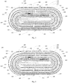
- Fig. 3 illustrates another arrangement of the protective layer 120, in which different from Fig. 2 , surfaces of the second straight segment 225 and the third bent segment 226 towards the center of the battery cell 200 are further provided with the protective layer 120, respectively.
- the second current collector 240 may include a fourth bent segment 242, a third straight segment 243, a fifth bent segment 244, a fourth straight segment 245, a sixth bent segment 246, and a second tail segment 247 connected sequentially.
- the third straight segment 243 is disposed between the fourth bent segment 242 and the fifth bent segment 244, the sixth bent segment 246 is opposite to the fourth bent segment 242, the fourth straight segment 245 is disposed between the fifth bent segment 244 and the sixth bent segment 246, and the second tail segment 247 is connected with the sixth bent segment 246.
- the first current collector 220 includes a first tail segment 227, two surfaces of the first tail segment 227 are provided with the first active material layer 228, and along the winding direction of the battery cell 200, the first tail segment 227 is disposed between the fifth bent segment 244 and the sixth bent segment 246.
- the protective layer 120 may be disposed on at least a part of a surface of the second uncoated region 251 from the fourth bent segment 242 to the second tail segment 247.
- the protective layer 120 may avoid a short-circuit due to direct contact between the steel nail and the second current collector 240 and the first active material layer 228, reduce the discharge power of the internal short circuit, and avoid the thermal runaway, thereby improving the safety performance of the battery cell 200.
- ends of the first tail segment 227 and the second tail segment 247 may be respectively provided with an insulation paste to enhance the safety performance of the battery cell 200.
- a surface of the second uncoated region 251 from the fifth bent segment 244 to the sixth bent segment 246 is provided with the protective layer 120. It is understood that surfaces of the fifth bent segment 244, the fourth straight segment 245 and the sixth bent segment 246 are provided with the protective layer 120.
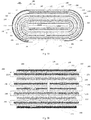
- Fig. 5 shows another arrangement of the protective layer 120, in which different from Fig. 4 , and in the direction away from the center of the battery cell 200, the protective layer 120 is also provided on the surface of the second uncoated region 251 of the fourth bent segment 242.
- Fig. 6 shows another arrangement of the protective layer 120, in which different from Fig.
- the protective layer 120 is also provided on the surface of the second uncoated region 251 of the third straight segment 243 and the second tail segment 247 in the direction away from the center of the battery cell 200.
- Fig. 7 shows another arrangement of the protective layer 120, in which different from Fig. 6 , the protective layer 120 is also provided on the surface of the second uncoated region 251 of the sixth bent segment 246 in a direction facing the center of the battery cell 200.
- the protective layer 120 may also be respectively provided on surfaces of the first uncoated region 229 and the second uncoated region 251 at the same time to further enhance the safety performance of the battery cell 200.
- the protective layer 120 may be provided on at least a part of the surface of the first uncoated region 229 from the first starting segment 221 to the third bent segment 226; meanwhile, the protective layer 120 may also be provided on at least a part of the surface of the second uncoated region 251 from the fourth bent segment 242 to the second tail segment 247. The more the protective layer 120 is disposed on the surfaces of the first uncoated region 229 and the second uncoated region 251, the less the probability that the corresponding current collector participates in the internal short circuit is, and the higher the safety performance of the battery cell is.
- the protective layer 120 is provided on two surfaces of the first uncoated region 229 of the first starting segment 221 and the first bent segment 222, and the protective layer 120 is also provided on the surface of the first straight segment 223 and the second bent segment 224 towards the center of the battery cell 200. Meanwhile, in the direction away from the center of the battery cell 200, the surface of the second uncoated region 251 from the fifth bent segment 244 to the sixth bent segment 246 is also provided with the protective layer 120.
- Fig. 9 shows another arrangement of the protective layer 120, in which different from Fig. 8 , the protective layer 120 is also provided on the surface of the second uncoated region 251 of the fourth bent segment 242.
- Fig. 10 shows another arrangement of the protective layer 120, in which different from Fig. 9 , and in the direction away from the center of the battery cell 200, the protective layer 120 is also provided on the surface of the second uncoated region 251 of the third straight segment 243 and the second tail segment 247.
- Fig. 11 shows another arrangement of the protective layer 120, in which different from Fig. 10 , and in the direction facing the center of the battery cell 200, the protective layer 120 is also provided on the surface of the second uncoated region 251 of the sixth bent segment 246.
- Fig. 12 shows another arrangement of the protective layer 120, in which different from Fig. 8 , and in the direction towards the center of the battery cell 200, the protective layer 120 is also provided on the surface of the first uncoated region 229 of the second straight segment 225 and the third bent segment 226.
- Fig. 13 shows another arrangement of the protective layer 120, in which different from Fig. 12 , and in the direction away from the center of the battery cell 200, the protective layer 120 is also provided on the surface of the second uncoated region 251 of the fourth bent segment 242.
- Fig. 14 shows another arrangement of the protective layer 120, in which different from Fig.
- Fig. 15 shows another arrangement of the protective layer 120, in which different from Fig. 14 , and in the direction facing the center of the battery cell 200, the protective layer 120 is also provided on the surface of the second uncoated region 251 of the sixth bent segment 246.
- a ratio of the thickness of the protective layer 120 to the thickness of the first current collector 220 is greater than or equal to 0.5 and less than or equal to 20. In some embodiments, a ratio of the thickness of the protective layer 120 to the thickness of the first active material layer 228 is greater than or equal to 0.25 and less than or equal to 1. In some embodiments, a ratio of the thickness of the protective layer 120 provided on the separator 260 to the thickness of the separator 260 is greater than or equal to 0.4 and less than or equal to 1.5.
- the battery cell 200 may further include a first electrode tab 270 and a second electrode tab 280, as shown in Figs. 16 to 19 .
- the first active material layer 228 is provided with a first groove 271, and the first electrode tab 270 is disposed within the first groove 271 to improve the energy density of the battery cell 200; alternatively, the first electrode tab 270 may be provided on the surface of the first uncoated region 229.
- the second active material layer 250 is provided with a second groove 281, and the second electrode tab 280 is disposed within the second groove 281 to improve the energy density of the battery cell 200; alternatively, the second electrode tab 280 may be provided on the surface of the second uncoated region 251.
- the first electrode tab 270 is disposed in the first groove 271 of the first active material layer 228 at the first straight segment 223, and the second electrode tab 280 is disposed in the second groove 281 of the second active material layer 250 at the second starting segment 241.
- the first electrode tab 270 is disposed in the first groove 271 of the first active material layer 228 at other positions, and the second electrode tab 280 is disposed in the second groove 281 of the second active material layer 250 at the second starting segment 241.
- Fig. 16 the first electrode tab 270 is disposed in the first groove 271 of the first active material layer 228 at the first straight segment 223, and the second electrode tab 280 is disposed in the second groove 281 of the second active material layer 250 at the second starting segment 241.
- the first electrode tab 270 is disposed in the first groove 271 of the first active material layer 228 at other positions
- the second electrode tab 280 is disposed in the second groove 281 of the second active material layer 250 at the second starting segment 241.
- the first electrode tab 270 is disposed in the first groove 271 of the first active material layer 228 at the first straight segment 223, and the second electrode tab 280 is disposed in the second groove 281 of the second active material layer 250 at other positions.
- the battery cell 200 illustrated in Figs. 1 to 15 may select any one of electrode tab arrangements in Figs. 16 to 20 based on actual needs.
- the first electrode tab 270 and the second electrode tab 280 may be arranged in the following way.
- the second current collector 240 may include an extension portion 248, and the extension portion 248 is connected with the second starting segment 241 and extends into the first starting segment 221 in the winding direction of the battery cell 200 (and along a direction opposite to the winding direction of the battery cell).
- the first electrode tab 270 is disposed on a surface of the first starting segment 221, and the second electrode tab 280 may be disposed on a surface of the extension portion 248.
- the arrangement position of the electrode tab may be arbitrarily changed based on the impedance design of the battery cell 200, and a thickness of the electrode tab may be ensured at the same time in such a way that the thickness of the electrode tab is smaller than the thickness of the separator, thereby preventing the electrode tab from being pressed, so as to reduce a risk of internal short-circuits caused by welding burrs piercing the separator after the electrode tab is pressed, thereby reducing the short-circuit points significantly, and enhancing the safety performance of the battery cell 200.
- the electrode tab may be formed by cutting the current collector, and finally welded at the head of the battery cell, thereby preventing the electrode tab from being pressed, significantly reducing the short-circuit points of the electrode tab, and improving the safety performance of the battery cell 200.
- the electrode tab adopts these two arrangements to reduce the internal resistance of the battery cell, and compensate for the discharge performance of the battery cell, so as to improve the safety performance of the battery cell while the discharge performance of the battery cell does not deteriorate.
- the battery cell 200 is formed by sequentially stacking a plurality of first electrode sheets 210, a plurality of separators 260, and a plurality of second electrode sheets 230.
- Each first electrode sheet 210 is provided with the first electrode tab 270
- each second electrode sheet 230 is provided with the second electrode tab 280.
- a plurality of first electrode tabs 270 are welded to form one first electrode tab
- a plurality of second electrode tabs 280 are welded to form one second electrode tab.
- the second electrode sheet 230 is disposed at the outermost side of the battery cell 200, and a surface of the second current collector 240 towards the outermost side of the battery cell 200 is provided with the second uncoated region 251, the protective layer 120 is provided on at least a part of the surface of the second uncoated region 251. In some embodiments, the protective layer 120 may be provided on the uppermost surface and the lowermost surface of the battery cell 200.
- the second electrode sheet may be a cathode electrode sheet or may be an anode electrode sheet.
- the present application further discloses a battery, and the battery includes a packaging case and a battery cell 200.
- the battery cell 200 is disposed within the packaging case, and the battery cell 200 includes a first electrode sheet 210, a second electrode sheet 230, and a separator 260.
- the first electrode sheet 210 includes a first current collector 220, the first current collector 220 includes a first coated region provided with a first active material layer 228 and a first uncoated region 229 that is not provided with the first active material layer 228.
- the second electrode sheet 230 includes a second current collector 240, the second current collector 240 includes a second coated region provided with a second active material layer 250 and a second uncoated region 251 that is not provided with the second active material layer 250.
- the separator 260 is disposed between the first electrode sheet 210 and the second electrode sheet 230.
- the battery cell 200 is formed by winding or stacking the first electrode sheet 210, the separator 260 and the second electrode sheet 230 in sequence.
- a surface of at least one of the first uncoated region 229 and the second uncoated region 251 is provided with the protective layer 120, and the protective layer 120 has a porosity of 0% to 95%.
- the contact resistance of the electrode sheet may be increased, the discharge power may be lowered, and the thermal runaway probability of the battery cell 200 may be reduced, thereby improving the safety performance of the battery cell 200 and the battery.
- the thermal shrinkage of the separator 260 of the battery cell 200 may be improved, and the safety performance of the battery may be further enhanced.
- the thickness of the protective layer/ the thickness of the current collector, and the thickness of the protective layer/the thickness of the active material layer in the following embodiments refer to a ratio of the thickness of the protective layer to the thickness of the first current collector or the second current collector, and a ratio of the thickness of the protective layer to the thickness of the first active material layer or the second active material layer, respectively, in which the protective layer is provided on the uncoated region of the first current collector or the second current collector.
- the battery cells manufactured by the above embodiments 1-48 and comparative examples 1-3 are subjected to performance tests, including nail pass rate, ignition ratio, discharging ratio, battery cell internal resistance, energy density (ED), etc., and various performances may be tested by referring to the following test methods.
- the test method and judgment conditions for the nail pass rate include: 1 charging process: charging the battery cell to 4.4V with a constant current of 0.7C, and then charging the battery cell to a charge current of 0.02C with a constant voltage of 4.4V; 2 nailing process: at a temperature of 25°C, using a steel nail with a diameter of 4 mm to pierce the center of the surface of the battery cell at a speed of 30 mm/s; 3 counting the battery cell burning situations: if the battery cell does not burn, it is recorded as passing the nail test; otherwise, it is invalid.
- the test method and judgment conditions for the ignition of the battery cell caused by the pressure cycle include: 1 disposing the battery cell between two flat glass plates while applying a pressure of 0.3 MPa; 2 charging and discharging process: charging the battery cell to 4.4V with a constant current of 0.7C, charging the battery cell to a charge current of 0.02C with a constant voltage of 4.4V, leaving it to stand still for 5 minutes, discharging the battery cell to 3V with a constant discharge current of 0.5C, and repeating this charging and discharging process for 20 times; 3 counting battery cell burning situations.
- the test method for internal resistance (impedance) of the battery cell includes: applying 1000Hz and 50mA disturbance to the battery cell by means of a battery internal resistance tester (AT520L) to obtain the AC (alternating current) internal resistance of the battery cell.
- AT520L battery internal resistance tester
- the calculation method of energy density includes: measuring the thickness of the battery cell with a battery thickness gauge, and calculating the energy density of the battery cell (see the following formula):
- ED min capacity ⁇ plateform voltage a length of the cell ⁇ a width of the cell ⁇ a thickness of the cell in which, the cell capacity is 3.3Ah, and the cell platform voltage is 3.88V.
- the protective layer 120 is provided on the uncoated region of the current collector, or the protective layer 120 is provided on the surfaces of both of the uncoated region and the separator so as to improve the nail pass rate of the battery cell, i.e., enhance the safety performance of the battery cell.
- the battery cell coated with the protective layer on the surfaces of both of the uncoated region and the separator has a higher nail pass rate than the battery cell only coated with the protective layer on the surface of the uncoated region, that is, the safety performance of the battery cell coated with the protective layer on the surfaces of the uncoated region and the separator is better than that of the battery cell only coated with the protective layer on the surface of the uncoated region.
Landscapes
- Chemical & Material Sciences (AREA)
- Chemical Kinetics & Catalysis (AREA)
- Electrochemistry (AREA)
- General Chemical & Material Sciences (AREA)
- Engineering & Computer Science (AREA)
- Manufacturing & Machinery (AREA)
- Materials Engineering (AREA)
- Composite Materials (AREA)
- Secondary Cells (AREA)
- Battery Electrode And Active Subsutance (AREA)
- Connection Of Batteries Or Terminals (AREA)
- Cell Electrode Carriers And Collectors (AREA)
Abstract
Description
- The present application relates to a field of electrochemical devices, more particularly to an electrode sheet, a battery cell, and a battery.
- With the intelligent development of terminal equipment, a lithium-ion battery adaptive has a constantly increased volumetric energy density, and the resulting safety problem is increasingly prominent, such as an explosion event due to a short circuit inside the battery or a puncture of the battery during the disassembly. There is no mature solution in the industry regarding how to effectively prevent an internal short circuit of a battery cell from causing severe thermal runaway, which leads to the explosion of the battery cell.
- The present application aims to solve at least one of the technical problems existing in the related art. Accordingly, one aspect of the present application proposes an electrode sheet.
- The electrode sheet according to embodiments of the present application includes a current collector and a protective layer. The current collector includes a coated region provided with an active material layer and an uncoated region without being provided with the active material layer. The protective layer is provided on at least a part of a surface of the uncoated region, and in which the protective layer has a porosity of 0% to 95%.
- In some embodiments, the protective layer has a conductivity of 0 S/m to 3.5×10⁷ S/m, and a material of the protective layer includes at least one of an inorganic oxide, a high molecular polymer or a non-metallic simple substance.
- Another aspect of the present application also provides a battery cell that may effectively reduce its internal short circuit points and improve its safety performance.
- The battery cell according to embodiments of the present application includes a first electrode sheet, a second electrode sheet, and a separator. The first electrode sheet includes a first current collector, and the first current collector includes a first coated region provided with a first active material layer and a first uncoated region without being provided with the first active material layer. The second electrode sheet includes a second current collector, and the second current collector includes a second coated region provided with a second active material layer and a second uncoated region without being provided with the second active material layer. The separator is disposed between the first electrode sheet and the second electrode sheet. The battery cell is formed by winding or stacking the first electrode sheet, the separator, and the second electrode sheet in sequence. A protective layer is provided on a surface of at least one of the first uncoated region and the second uncoated region, and the protective layer has a porosity of 0% to 95%.
- For the battery cell according to embodiments of the present application, by providing the current collector with the protective layer, the contact resistance of the electrode sheet may be increased when this battery cell is internally short-circuited, and the discharge power and the thermal runaway probability of the battery cell may be reduced when the battery cell is internally short-circuited, thereby improving the safety performance of the battery cell. Additionally, the separator may also be provided with the protective layer to improve the thermal shrinkage of the separator, thereby further enhancing the safety performance of the battery cell.
- In some embodiments, the protective layer has a conductivity of 0 S/m to 3.5×10⁷ S/m, and a material of the protective layer includes at least one of an inorganic oxide, a high molecular polymer or a non-metallic simple substance.
- In some embodiments, the battery cell is formed by winding. The first current collector includes a first starting segment, a first bent segment, a first straight segment, a second bent segment, a second straight segment, and a third bent segment. The first bent segment is connected with the first starting segment, and a current collector opposite to the first starting segment and the first bent segment is defined as the first current collector. The first bent segment is disposed between the first starting segment and the first straight segment. The second bent segment is disposed between the first straight segment and the second straight segment. The third bent segment is connected with the second straight segment and opposite to the first bent segment. In a direction away from a center of the battery cell, a surface from the first straight segment to the third bent segment is provided with the first active material layer. The second current collector includes a second starting segment, two surfaces of the second starting segment are provided with the second active material layer, and along a winding direction of the battery cell, the second starting segment is disposed between the first bent segment and the second bent segment.
- In some embodiments, the protective layer is provided on two surfaces of the first uncoated region of the first starting segment, the protective layer is provided on two surfaces of the first uncoated region of the first bent segment, and in a direction facing the center of the battery cell, the protective layer is provided on at least a part of a surface of the first uncoated region from the first starting segment to the third bent segment.
- In some embodiments, the second current collector includes a fourth bent segment, a third straight segment, a fifth bent segment, a fourth straight segment, a sixth bent segment, and a second tail segment. The third straight segment is disposed between the fourth bent segment and the fifth bent segment. The sixth bent segment is opposite to the fourth bent segment, and the fourth straight segment is disposed between the fifth bent segment and the sixth bent segment. The second tail segment is connected with the sixth bent segment. The first current collector includes a first tail segment, two surfaces of the first tail segment are provided with the first active material layer, and along the winding direction of the battery cell, the first tail segment is disposed between the fifth bent segment and the sixth bent segment.
- In some embodiments, in the direction away from the center of the battery cell, the protective layer is provided on at least a part of a surface of the second uncoated region from the fourth bent segment to the second tail segment.
- In some embodiments, in a direction facing the center of the battery cell, the protective layer is provided on at least a part of a surface of the second uncoated region from the sixth bent segment to the second tail segment.
- In some embodiments, a thickness ratio of the protective layer to the first current collector is greater than or equal to 0.05 and less than or equal to 20. And a thickness ratio of the protective layer to the first active material layer is greater than or equal to 0.0025 and less than or equal to 1.
- In some embodiments, the battery cell further includes: a first electrode tab and a second electrode tab. The first active material layer is provided with a first groove, and the first electrode tab is disposed within the first groove or on a surface of the first uncoated region. The second active material layer is provided with a second groove, and the second electrode tab is disposed within the second groove or on a surface of the second uncoated region.
- In some embodiments, the second current collector further includes an extension portion connected with the second starting segment, and in the winding direction of the battery cell, the extension portion extends into the first starting segment.
- In some embodiments, the battery cell is formed by sequentially stacking a plurality of the first electrode sheets, a plurality of the separators, and a plurality of the second electrode sheets, the first electrode sheet is disposed at the outermost side of the battery cell, and a surface of the first current collector towards the outermost side of the battery cell is provided with the first uncoated region, the protective layer is provided on at least a part of a surface of the first uncoated region.
- In some embodiments, the protective layer is further provided on at least a part of a surface of the separator.
- Still another aspect of the present application provides a battery that has better safety performance.
- The battery according to embodiments of the present application includes a packaging case and a battery cell according to the above embodiments, and the battery cell is disposed within the packaging case.
- For the battery according to embodiments of the present application, by providing the current collector of the electrode sheet with the protective layer, the contact resistance of the electrode sheet may be increased when this battery is internally short-circuited, and the discharge power and the thermal runaway probability of the battery may be reduced when the battery is internally short-circuited, thereby improving the safety performance of the battery. Additionally, the separator may also be provided with the protective layer to improve the thermal shrinkage of the separator, thereby further enhancing the safety performance of the battery.
- These and other aspects and advantages of embodiments of the present application will become apparent and more readily appreciated from the following descriptions made with reference to the drawings, in which:
-
Fig. 1 is a sectional view of an electrode sheet according to an embodiment of the present application. -
Fig. 2 is a sectional view of a battery cell according to an embodiment of the present application. -
Fig. 3 is a sectional view of a battery cell according to another embodiment of the present application. -
Fig. 4 is a sectional view of a battery cell according to another embodiment of the present application. -
Fig. 5 is a sectional view of a battery cell according to another embodiment of the present application. -
Fig. 6 is a sectional view of a battery cell according to another embodiment of the present application. -
Fig. 7 is a sectional view of a battery cell according to another embodiment of the present application. -
Fig. 8 is a sectional view of a battery cell according to another embodiment of the present application. -
Fig. 9 is a sectional view of a battery cell according to another embodiment of the present application. -
Fig. 10 is a sectional view of a battery cell according to another embodiment of the present application. -
Fig. 1 1 is a sectional view of a battery cell according to another embodiment of the present application. -
Fig. 12 is a sectional view of a battery cell according to another embodiment of the present application. -
Fig. 13 is a sectional view of a battery cell according to another embodiment of the present application. -
Fig. 14 is a sectional view of a battery cell according to another embodiment of the present application. -
Fig. 15 is a sectional view of a battery cell according to another embodiment of the present application. -
Fig. 16 is a sectional view of a battery cell according to another embodiment of the present application. -
Fig. 17 is a sectional view of a battery cell according to another embodiment of the present application. -
Fig. 18 is a sectional view of a battery cell according to another embodiment of the present application. -
Fig. 19 is a sectional view of a battery cell according to another embodiment of the present application. -
Fig. 20 is a sectional view of a battery cell according to another embodiment of the present application. -
-
electrode sheet 100,current collector 110,active material layer 111,uncoated region 112,protective layer 120, -
battery cell 200,first electrode sheet 210, firstcurrent collector 220, - first starting
segment 221, firstbent segment 222, firststraight segment 223, secondbent segment 224, secondstraight segment 225, thirdbent segment 226,first tail segment 227, firstactive material layer 228, firstuncoated region 229, -
second electrode sheet 230, secondcurrent collector 240, -
second starting segment 241, fourthbent segment 242, thirdstraight segment 243, fifthbent segment 244, fourthstraight segment 245, sixthbent segment 246,second tail segment 247,extension portion 248, - second
active material layer 250, seconduncoated region 251, -
separator 260, -
first electrode tab 270,first groove 271,second electrode tab 280,second groove 281. - Embodiments of the present application will be described in detail and examples of the embodiments will be illustrated in the accompanying drawings, where same or similar reference numerals are used to indicate same or similar elements or elements with same or similar functions. The embodiments described herein with reference to the accompanying drawings are explanatory, illustrative, and used to generally understand the present application. The embodiments shall not be construed to limit the present application.
- An electrode sheet, a
battery cell 200, and a battery 300 according to embodiments of the present application will be described below with reference to the accompanying drawings. - As illustrated in
Fig. 2 , theelectrode sheet 100 according to embodiments of the present application includes acurrent collector 110 and aprotective layer 120. Thecurrent collector 110 includes a coated region provided with anactive material layer 111 and anuncoated region 112 without being provided with theactive material layer 111. Theprotective layer 120 is provided on at least a part of a surface of theuncoated region 112, and theprotective layer 120 may also be provided on the entire surface of theuncoated region 112, in which theprotective layer 120 has a porosity of 0% to 95%. - For the
electrode sheet 100 according to the embodiments of the present application, by providing thecurrent collector 110 with theprotective layer 120, the contact resistance of the electrode sheet may be increased when thebattery cell 200 wound or stacked by the electrode sheet is internally short-circuited, and the discharge power and the thermal runaway probability of thebattery cell 200 may be reduced when thebattery cell 200 is internally short-circuited, thereby improving the safety performance of thebattery cell 200. - According to some embodiments of the present application, the porosity of the
protective layer 120 may be 0% to 50%. That is, the porosity of theprotective layer 120 may be greater than or equal to 0 and less than or equal to 50%. It should be noted that when the porosity of theprotective layer 120 has a value range of 0% to 50%, the contact resistance may be increased better when the battery cell is internally short-circuited, and the discharge power and the thermal runaway probability of thebattery cell 200 may be reduced when thebattery cell 200 is internally short-circuited, thereby better improving the safety performance of thebattery cell 200. In some embodiments, the porosity of theprotective layer 120 may be 0% to 50%. In some embodiments, the porosity of theprotective layer 120 may be 0% to 19%. In some embodiments, the porosity of theprotective layer 120 may be 0% to 15%. In some embodiments, the porosity of theprotective layer 120 may be 0% to 10%. As the porosity of theprotective layer 120 is decreased, the safety performance of thebattery cell 200 is better. - According to some embodiments of the present application, the
protective layer 120 may have a conductivity of 0 S/m to 3.5×10⁷ S/m. That is, the conductivity of theprotective layer 120 may have a value range which is greater than or equal to 0 S/m, and less than or equal to 3.5×10⁷ S/m. In some embodiments, when the conductivity of theprotective layer 120 has a value range of 0 S/m to 9.9×10⁵ S/m, the contact resistance of the electrode sheet may be increased better when the battery cell is internally short-circuited, and the discharge power and the thermal runaway probability of thebattery cell 200 may be reduced when thebattery cell 200 is internally short-circuited, thereby improving the safety performance of the battery cell better. In some embodiments, the conductivity of theprotective layer 120 may be 0 S/m to 4×10⁵ S/m. In some embodiments, the conductivity of theprotective layer 120 may be 0 S/m to 9×10-14 S/m. In some embodiments, the conductivity of theprotective layer 120 may be 0 S/m to 4×10-14 S/m. - According to some embodiments of the present application, a material of the
protective layer 120 includes at least one of an inorganic oxide, a high molecular polymer or a non-metallic simple substance. It should be understood that, in some embodiments, the material of theprotective layer 120 may be a combination of an inorganic oxide and a high molecular polymer, or a combination of an inorganic oxide and a non-metallic simple substance. In some embodiments, the inorganic oxide may be at least one of magnesium oxide, calcium oxide, silicon oxide, lithium cobalt oxide or boehmite, etc. In some embodiments, the high molecular polymer may be at least one of polypropylene, polyvinyl chloride, polyethylene, epoxy resin, polyacrylate, or urethane rubber, etc. In some embodiments, the non-metallic simple substance may be graphite. Additionally, in some embodiments, the protective layer may also be an adhesive tape, a major ingredient of the adhesive tape is a mixture composed of polyethylene terephthalate, butyl rubber, aluminum oxide, etc., or may also be a mixture composed of other polymers, inorganic oxides, non-metallic simple substances, etc., for example, a mixture composed of two or more of polypropylene, polyvinyl chloride, polyethylene, epoxy resin, polyacrylate, urethane rubber, magnesium oxide, calcium oxide, silicon oxide, boehmite, graphite, etc. - As illustrated in
Figs. 2 to 20 , a plurality of battery cells of different structures prepared using the electrode sheet structure described inFig. 1 are shown. Thebattery cell 200 includes afirst electrode sheet 210, asecond electrode sheet 230, and aseparator 260. At least one of thefirst electrode sheet 210 and thesecond electrode sheet 230 adopts the electrode sheet structure having theprotective layer 120, as illustrated inFig. 1 . Specifically, as shown inFig. 2 , thefirst electrode sheet 210 includes a firstcurrent collector 220, the firstcurrent collector 220 includes a first coated region provided with a firstactive material layer 228, and a firstuncoated region 229 that is not provided with the firstactive material layer 228. Thesecond electrode sheet 230 includes a secondcurrent collector 240, the secondcurrent collector 240 includes a second coated region provided with a secondactive material layer 250, and a seconduncoated region 251 that is not provided with the secondactive material layer 250. Theseparator 260 is disposed between thefirst electrode sheet 210 and thesecond electrode sheet 230. Theprotective layer 120 is provided on a surface of at least one of the firstuncoated region 229 and the seconduncoated region 251, and theprotective layer 120 has a porosity of 0% to 95%. In some embodiments, the porosity of theprotective layer 120 may be 0% to 19%. - The
battery cell 200 may be formed by winding or stacking thefirst electrode sheet 210, theseparator 260 and thesecond electrode sheet 230 in sequence. For example, as illustrated inFig. 2 , thebattery cell 200 may be formed by sequentially winding thefirst electrode sheet 210, theseparator 260 and thesecond electrode sheet 230. For another example, as illustrated inFig. 20 , thebattery cell 200 is formed by sequentially stacking thefirst electrode sheet 210, theseparator 260 and thesecond electrode sheet 230. - For the
battery cell 200 according to the embodiments of the present application, by providing a surface of at least one of the firstuncoated region 229 and the seconduncoated region 251 with theprotective layer 120, when thebattery cell 200 is internally short-circuited, the contact resistance of the electrode sheet may be increased, the discharge power may be lowered, and the thermal runaway probability of thebattery cell 200 may be reduced, thereby improving the safety performance of thebattery cell 200. - According to some embodiments of the present application, the conductivity of the
protective layer 120 may be 0 S/m to 3.5×10⁷ S/m. The lower the conductivity of theprotective layer 120 is, when thebattery cell 200 is internally short-circuited, the greater the contact resistance of theelectrode sheet 100 is, the lower the thermal runaway probability of thebattery cell 200 is, and thus the higher the safety performance of thebattery cell 200 is. According to some embodiments of the present application, the material of theprotective layer 120 includes at least one of an inorganic oxide, a high molecular polymer or a non-metallic simple substance, and the material of the protective layer may include the above-mentioned materials. In some embodiments, theprotective layer 120 has a pore size ranging from 1 nm to 100 µm. In some embodiments, theprotective layer 120 has a pore size ranging from 1 nm to 50 µm. - In some embodiments, the
protective layer 120 may have a thickness of 0.1 µm to 200 µm. When the thickness of theprotective layer 120 is greater than 200 µm, the energy density of the battery cell is greatly affected. When the thickness of theprotective layer 120 is smaller than 0.1 µm, the safety performance of the battery cell may not be improved significantly. The thicker the protective layer is, the smaller the probability that the current collector of the electrode sheet participates in the internal short circuit will be, and the higher the safety performance of the battery cell will be. In some embodiments, the thickness of theprotective layer 120 may be 0.5 µm to 100 µm. In some embodiments, the thickness of theprotective layer 120 may be 5 µm to 50 µm. The thickness of the protective layer is equal to or greater than a thickness of the current collector/20, and equal to or less than a thickness of the active material layer, and in such a case, the energy density of the battery cell will not be affected. - In some embodiments, the thickness of the
current collector 110 may be 5 µm to 13 µm. According to some embodiments of the present application, a ratio of the thickness of theprotective layer 120 to the thickness of thecurrent collector 110 ranges from 0.05 to 20, in which the current collector herein may be understood as the firstcurrent collector 220 or the secondcurrent collector 240, and theprotective layer 120 is a protective layer provided on the corresponding current collector. In some embodiments, the ratio of the thickness of theprotective layer 120 to thecurrent collector 110 ranges from 0.5 to 10. According to some embodiments of the present application, a ratio of the thickness of theprotective layer 120 to the thickness of theactive material layer 111 ranges from 0.0025 to 1, in which the active material layer herein may be understood as the firstactive material layer 228 or the secondactive material layer 250, and theprotective layer 120 is a protective layer provided on the same current collector as the active material layer. In some embodiments, the ratio of the thickness of theprotective layer 120 to the thickness of theactive material layer 111 ranges from 0.1 to 1. In some embodiments, the ratio of the thickness of theprotective layer 120 to the thickness of theactive material layer 111 ranges from 0.25 to 1. - In some embodiments, in the battery cell structure shown in
Figs. 2 to 20 , theprotective layer 120 may also be provided on at least a part or all of a surface of the separator 260 (not illustrated). It could be understood that theprotective layer 120 may be provided on at least a part or all of one surface of theseparator 260, or theprotective layer 120 may be provided on at least a part or all of two surfaces of theseparator 260. By providing theprotective layer 120 on at least a part of the surface of theseparator 260, the thermal shrinkage of theseparator 260 may be improved, and the safety performance of thebattery cell 200 may be further improved. In some embodiments, a ratio of the thickness of theprotective layer 120 on theseparator 260 to the thickness of theseparator 260 ranges from 0.4 to 1.5. If the ratio is less than 0.4, the thermal shrinkage of the separator may not be improved significantly, the internal short-circuit point may not be reduced effectively, and the nail performance of the battery cell is not improved. If the ratio is greater than 1.5, the volumetric energy density of the battery cell will be affected, and at the same time, the transmission distance of Li+ (lithium ion) is increased, which affects the discharge performance of the battery cell. In some embodiments, the thickness of theseparator 260 is 3 to 10 µm. In some embodiments, the ratio of the thickness of theprotective layer 120 on theseparator 260 to the thickness of theseparator 260 ranges from 0.4 to 1. The thicker the protective layer on the separator is, the higher the safety performance of the battery cell is. - In some embodiments of the present application, as illustrated in
Fig. 2 , thebattery cell 200 may be formed by winding, and along a winding direction of the firstcurrent collector 220, the firstcurrent collector 220 may include afirst starting segment 221, a firstbent segment 222, a firststraight segment 223, a secondbent segment 224, a secondstraight segment 225, and a thirdbent segment 226 connected in sequence. The firstbent segment 222 is connected with thefirst starting segment 221, and a current collector opposite to thefirst starting segment 221 and the firstbent segment 222 is defined as the firstcurrent collector 220, that is, thebattery cell 200 is not internally provided with an area where the firstcurrent collector 220 is opposite to the secondcurrent collector 240. In other words, after thefirst starting segment 221 and the firstbent segment 222 of the firstcurrent collector 220 finish the winding, asecond starting segment 241 of the secondcurrent collector 240 starts to wind. At this time, the firstcurrent collector 220 is wound together with the secondcurrent collector 240. When the secondstraight segment 225 and the thirdbent segment 226 of the firstcurrent collector 220 are wound, a partial structure of the secondstraight segment 225 is opposite to thefirst starting segment 221, and the thirdbent segment 226 is opposite to the firstbent segment 222. With this structure, no internal short-circuit will occur between the firstcurrent collector 220 and the secondcurrent collector 240, and a plurality of separator layers may be omitted, which may not only enhance the safety performance of thebattery cell 200, but also improve the energy density of thebattery cell 200. - As illustrated in
Fig. 2 , the firstbent segment 222 is disposed between thefirst starting segment 221 and the firststraight segment 223, the secondbent segment 224 is disposed between the firststraight segment 223 and the secondstraight segment 225, the thirdbent segment 226 is connected with the secondstraight segment 225, and the thirdbent segment 226 is opposite to the firstbent segment 222. In a direction away from a center of thebattery cell 200, a surface from the firststraight segment 223 to the thirdbent segment 226 is provided with the firstactive material layer 228. The secondcurrent collector 240 may include thesecond starting segment 241, two surfaces of thesecond starting segment 241 are provided with the secondactive material layer 250, and along a winding direction of thebattery cell 200, thesecond starting segment 241 is disposed between the firstbent segment 222 and the secondbent segment 224. Theprotective layer 120 may be disposed on at least a part of a surface of the firstuncoated region 229 from thefirst starting segment 221 to the thirdbent segment 226. - In some embodiments, as illustrated in
Fig. 2 , theprotective layer 120 is provided on two surfaces of the firstuncoated region 229 of thefirst starting segment 221, theprotective layer 120 is provided on two surfaces of the firstuncoated region 229 of the firstbent segment 222, and surfaces of the firststraight segment 223 and the secondbent segment 224 towards a center of thebattery cell 200 are respectively provided with theprotective layer 120.Fig. 3 illustrates another arrangement of theprotective layer 120, in which different fromFig. 2 , surfaces of the secondstraight segment 225 and the thirdbent segment 226 towards the center of thebattery cell 200 are further provided with theprotective layer 120, respectively. - According to some embodiments of the present application, in a winding direction of the second
current collector 240, the secondcurrent collector 240 may include a fourthbent segment 242, a thirdstraight segment 243, a fifthbent segment 244, a fourthstraight segment 245, a sixthbent segment 246, and asecond tail segment 247 connected sequentially. The thirdstraight segment 243 is disposed between the fourthbent segment 242 and the fifthbent segment 244, the sixthbent segment 246 is opposite to the fourthbent segment 242, the fourthstraight segment 245 is disposed between the fifthbent segment 244 and the sixthbent segment 246, and thesecond tail segment 247 is connected with the sixthbent segment 246. The firstcurrent collector 220 includes afirst tail segment 227, two surfaces of thefirst tail segment 227 are provided with the firstactive material layer 228, and along the winding direction of thebattery cell 200, thefirst tail segment 227 is disposed between the fifthbent segment 244 and the sixthbent segment 246. Theprotective layer 120 may be disposed on at least a part of a surface of the seconduncoated region 251 from the fourthbent segment 242 to thesecond tail segment 247. When a sharp object (like a steel nail) pierces thebattery cell 200, theprotective layer 120 may avoid a short-circuit due to direct contact between the steel nail and the secondcurrent collector 240 and the firstactive material layer 228, reduce the discharge power of the internal short circuit, and avoid the thermal runaway, thereby improving the safety performance of thebattery cell 200. In some embodiments, ends of thefirst tail segment 227 and thesecond tail segment 247 may be respectively provided with an insulation paste to enhance the safety performance of thebattery cell 200. - In some embodiments, as illustrated in
Fig. 4 , in a direction away from the center of thebattery cell 200, a surface of the seconduncoated region 251 from the fifthbent segment 244 to the sixthbent segment 246 is provided with theprotective layer 120. It is understood that surfaces of the fifthbent segment 244, the fourthstraight segment 245 and the sixthbent segment 246 are provided with theprotective layer 120. In some embodiments,Fig. 5 shows another arrangement of theprotective layer 120, in which different fromFig. 4 , and in the direction away from the center of thebattery cell 200, theprotective layer 120 is also provided on the surface of the seconduncoated region 251 of the fourthbent segment 242. In some embodiments,Fig. 6 shows another arrangement of theprotective layer 120, in which different fromFig. 5 , theprotective layer 120 is also provided on the surface of the seconduncoated region 251 of the thirdstraight segment 243 and thesecond tail segment 247 in the direction away from the center of thebattery cell 200. In some embodiments,Fig. 7 shows another arrangement of theprotective layer 120, in which different fromFig. 6 , theprotective layer 120 is also provided on the surface of the seconduncoated region 251 of the sixthbent segment 246 in a direction facing the center of thebattery cell 200. - In some embodiments, the
protective layer 120 may also be respectively provided on surfaces of the firstuncoated region 229 and the seconduncoated region 251 at the same time to further enhance the safety performance of thebattery cell 200. For example, theprotective layer 120 may be provided on at least a part of the surface of the firstuncoated region 229 from thefirst starting segment 221 to the thirdbent segment 226; meanwhile, theprotective layer 120 may also be provided on at least a part of the surface of the seconduncoated region 251 from the fourthbent segment 242 to thesecond tail segment 247. The more theprotective layer 120 is disposed on the surfaces of the firstuncoated region 229 and the seconduncoated region 251, the less the probability that the corresponding current collector participates in the internal short circuit is, and the higher the safety performance of the battery cell is. - Specifically, as illustrated in
Fig. 8 , theprotective layer 120 is provided on two surfaces of the firstuncoated region 229 of thefirst starting segment 221 and the firstbent segment 222, and theprotective layer 120 is also provided on the surface of the firststraight segment 223 and the secondbent segment 224 towards the center of thebattery cell 200. Meanwhile, in the direction away from the center of thebattery cell 200, the surface of the seconduncoated region 251 from the fifthbent segment 244 to the sixthbent segment 246 is also provided with theprotective layer 120. - In some embodiments,
Fig. 9 shows another arrangement of theprotective layer 120, in which different fromFig. 8 , theprotective layer 120 is also provided on the surface of the seconduncoated region 251 of the fourthbent segment 242.Fig. 10 shows another arrangement of theprotective layer 120, in which different fromFig. 9 , and in the direction away from the center of thebattery cell 200, theprotective layer 120 is also provided on the surface of the seconduncoated region 251 of the thirdstraight segment 243 and thesecond tail segment 247.Fig. 11 shows another arrangement of theprotective layer 120, in which different fromFig. 10 , and in the direction facing the center of thebattery cell 200, theprotective layer 120 is also provided on the surface of the seconduncoated region 251 of the sixthbent segment 246. - In some embodiments,
Fig. 12 shows another arrangement of theprotective layer 120, in which different fromFig. 8 , and in the direction towards the center of thebattery cell 200, theprotective layer 120 is also provided on the surface of the firstuncoated region 229 of the secondstraight segment 225 and the thirdbent segment 226.Fig. 13 shows another arrangement of theprotective layer 120, in which different fromFig. 12 , and in the direction away from the center of thebattery cell 200, theprotective layer 120 is also provided on the surface of the seconduncoated region 251 of the fourthbent segment 242.Fig. 14 shows another arrangement of theprotective layer 120, in which different fromFig. 13 , and in the direction away from the center of thebattery cell 200, theprotective layer 120 is also provided on the surface of the seconduncoated region 251 of the thirdstraight segment 243 and thesecond tail segment 247.Fig. 15 shows another arrangement of theprotective layer 120, in which different fromFig. 14 , and in the direction facing the center of thebattery cell 200, theprotective layer 120 is also provided on the surface of the seconduncoated region 251 of the sixthbent segment 246. - According to some embodiments of the present application, a ratio of the thickness of the
protective layer 120 to the thickness of the firstcurrent collector 220 is greater than or equal to 0.5 and less than or equal to 20. In some embodiments, a ratio of the thickness of theprotective layer 120 to the thickness of the firstactive material layer 228 is greater than or equal to 0.25 and less than or equal to 1. In some embodiments, a ratio of the thickness of theprotective layer 120 provided on theseparator 260 to the thickness of theseparator 260 is greater than or equal to 0.4 and less than or equal to 1.5. - According to some embodiments of the present application, the
battery cell 200 may further include afirst electrode tab 270 and asecond electrode tab 280, as shown inFigs. 16 to 19 . In some embodiments, the firstactive material layer 228 is provided with afirst groove 271, and thefirst electrode tab 270 is disposed within thefirst groove 271 to improve the energy density of thebattery cell 200; alternatively, thefirst electrode tab 270 may be provided on the surface of the firstuncoated region 229. In some embodiments, the secondactive material layer 250 is provided with asecond groove 281, and thesecond electrode tab 280 is disposed within thesecond groove 281 to improve the energy density of thebattery cell 200; alternatively, thesecond electrode tab 280 may be provided on the surface of the seconduncoated region 251. - Specifically, as illustrated in
Fig. 16 , thefirst electrode tab 270 is disposed in thefirst groove 271 of the firstactive material layer 228 at the firststraight segment 223, and thesecond electrode tab 280 is disposed in thesecond groove 281 of the secondactive material layer 250 at thesecond starting segment 241. In some embodiments, as illustrated inFig. 17 , thefirst electrode tab 270 is disposed in thefirst groove 271 of the firstactive material layer 228 at other positions, and thesecond electrode tab 280 is disposed in thesecond groove 281 of the secondactive material layer 250 at thesecond starting segment 241. In some embodiments, as illustrated inFig. 18 , thefirst electrode tab 270 is disposed in thefirst groove 271 of the firstactive material layer 228 at the firststraight segment 223, and thesecond electrode tab 280 is disposed in thesecond groove 281 of the secondactive material layer 250 at other positions. Thebattery cell 200 illustrated inFigs. 1 to 15 may select any one of electrode tab arrangements inFigs. 16 to 20 based on actual needs. - The
first electrode tab 270 and thesecond electrode tab 280 may be arranged in the following way. As illustrated inFig. 19 , the secondcurrent collector 240 may include anextension portion 248, and theextension portion 248 is connected with thesecond starting segment 241 and extends into thefirst starting segment 221 in the winding direction of the battery cell 200 (and along a direction opposite to the winding direction of the battery cell). Thefirst electrode tab 270 is disposed on a surface of thefirst starting segment 221, and thesecond electrode tab 280 may be disposed on a surface of theextension portion 248. - Thus, the arrangement position of the electrode tab may be arbitrarily changed based on the impedance design of the
battery cell 200, and a thickness of the electrode tab may be ensured at the same time in such a way that the thickness of the electrode tab is smaller than the thickness of the separator, thereby preventing the electrode tab from being pressed, so as to reduce a risk of internal short-circuits caused by welding burrs piercing the separator after the electrode tab is pressed, thereby reducing the short-circuit points significantly, and enhancing the safety performance of thebattery cell 200. Additionally, the electrode tab may be formed by cutting the current collector, and finally welded at the head of the battery cell, thereby preventing the electrode tab from being pressed, significantly reducing the short-circuit points of the electrode tab, and improving the safety performance of thebattery cell 200. The electrode tab adopts these two arrangements to reduce the internal resistance of the battery cell, and compensate for the discharge performance of the battery cell, so as to improve the safety performance of the battery cell while the discharge performance of the battery cell does not deteriorate. - According to some embodiments of the present application, as illustrated in
Fig. 20 , thebattery cell 200 is formed by sequentially stacking a plurality offirst electrode sheets 210, a plurality ofseparators 260, and a plurality ofsecond electrode sheets 230. Eachfirst electrode sheet 210 is provided with thefirst electrode tab 270, and eachsecond electrode sheet 230 is provided with thesecond electrode tab 280. A plurality offirst electrode tabs 270 are welded to form one first electrode tab, and a plurality ofsecond electrode tabs 280 are welded to form one second electrode tab. Thesecond electrode sheet 230 is disposed at the outermost side of thebattery cell 200, and a surface of the secondcurrent collector 240 towards the outermost side of thebattery cell 200 is provided with the seconduncoated region 251, theprotective layer 120 is provided on at least a part of the surface of the seconduncoated region 251. In some embodiments, theprotective layer 120 may be provided on the uppermost surface and the lowermost surface of thebattery cell 200. The second electrode sheet may be a cathode electrode sheet or may be an anode electrode sheet. - In some embodiments, the present application further discloses a battery, and the battery includes a packaging case and a
battery cell 200. Thebattery cell 200 is disposed within the packaging case, and thebattery cell 200 includes afirst electrode sheet 210, asecond electrode sheet 230, and aseparator 260. Thefirst electrode sheet 210 includes a firstcurrent collector 220, the firstcurrent collector 220 includes a first coated region provided with a firstactive material layer 228 and a firstuncoated region 229 that is not provided with the firstactive material layer 228. Thesecond electrode sheet 230 includes a secondcurrent collector 240, the secondcurrent collector 240 includes a second coated region provided with a secondactive material layer 250 and a seconduncoated region 251 that is not provided with the secondactive material layer 250. Theseparator 260 is disposed between thefirst electrode sheet 210 and thesecond electrode sheet 230. Thebattery cell 200 is formed by winding or stacking thefirst electrode sheet 210, theseparator 260 and thesecond electrode sheet 230 in sequence. A surface of at least one of the firstuncoated region 229 and the seconduncoated region 251 is provided with theprotective layer 120, and theprotective layer 120 has a porosity of 0% to 95%. - For the battery according to the embodiments of the present application, by providing the surface of at least one of the first
uncoated region 229 and the seconduncoated region 251 with theprotective layer 120, when thebattery cell 200 is internally short-circuited, the contact resistance of the electrode sheet may be increased, the discharge power may be lowered, and the thermal runaway probability of thebattery cell 200 may be reduced, thereby improving the safety performance of thebattery cell 200 and the battery. In addition, by providing the aboveprotective layer 120 on theseparator 260, the thermal shrinkage of theseparator 260 of thebattery cell 200 may be improved, and the safety performance of the battery may be further enhanced. - Next, some specific embodiments are given to elaborate the present application. For example, in a case where the first
current collector 220 is a copper foil, thefirst electrode tab 270 is a nickel (Ni) electrode tab, the secondcurrent collector 240 is an aluminum (Al) foil, and thesecond electrode tab 280 is an aluminum (Al) electrode tab, the thickness of the protective layer/ the thickness of the current collector, and the thickness of the protective layer/the thickness of the active material layer in the following embodiments refer to a ratio of the thickness of the protective layer to the thickness of the first current collector or the second current collector, and a ratio of the thickness of the protective layer to the thickness of the first active material layer or the second active material layer, respectively, in which the protective layer is provided on the uncoated region of the first current collector or the second current collector. - Embodiment 1
Using the battery cell structure as shown inFig. 2 , a battery cell is manufactured after encapsulation, liquid injection, and formation. Theprotective layer 120 is an aluminum oxide layer. And theprotective layer 120 has a porosity of 19%, a thickness of 20 µm, and a conductivity of 8×10-14 S/m. A ratio of a thickness of theprotective layer 120 to a thickness of the current collector is 200%, while a ratio of the thickness of theprotective layer 120 to the thickness of the active material layer is 10%, it is understood that the current collector refers to the corresponding current collector provided with the protective layer 120 (i.e., the first current collector 220), and theprotective layer 120 and the active material layer refer to that disposed on the same current collector (i.e., the first active material layer 228). One surface of theseparator 260 is provided with theprotective layer 120, and a thickness of theprotective layer 120 to a thickness of theseparator 260 is 50%. - Embodiment 2
Theprotective layer 120 has the same parameters as that in Embodiment 1, the difference is that the battery cell structure shown inFig. 3 is adopted. - Embodiment 3
Theprotective layer 120 has the same parameters as that in Embodiment 1, the difference is that the battery cell structure shown inFig. 4 is adopted. - Embodiment 4
Theprotective layer 120 has the same parameters as that in Embodiment 1, the difference is that the battery cell structure shown inFig. 5 is adopted. - Embodiment 5
Theprotective layer 120 has the same parameters as that in Embodiment 1, the difference is that the battery cell structure shown inFig. 6 is adopted. - Embodiment 6
Theprotective layer 120 has the same parameters as that in Embodiment 1, the difference is that the battery cell structure shown inFig. 7 is adopted. - Embodiment 7
Theprotective layer 120 has the same parameters as that in Embodiment 1, the difference is that the battery cell structure shown inFig. 8 is adopted. - Embodiment 8
Theprotective layer 120 has the same parameters as that in Embodiment 1, the difference is that the battery cell structure shown inFig. 9 is adopted. - Embodiment 9
Theprotective layer 120 has the same parameters as that in Embodiment 1, the difference is that the battery cell structure shown inFig. 10 is adopted. - Embodiment 10
Theprotective layer 120 has the same parameters as that in Embodiment 1, the difference is that the battery cell structure shown inFig. 11 is adopted. - Embodiment 11
Theprotective layer 120 has the same parameters as that in Embodiment 1, the difference is that the battery cell structure shown inFig. 12 is adopted. - Embodiment 12
Theprotective layer 120 has the same parameters as that in Embodiment 1, the difference is that the battery cell structure shown inFig. 13 is adopted. - Embodiment 13
Theprotective layer 120 has the same parameters as that in Embodiment 1, the difference is that the battery cell structure shown inFig. 14 is adopted. - Embodiment 14
Theprotective layer 120 has the same parameters as that in Embodiment 1, the difference is that the battery cell structure shown inFig. 15 is adopted. - Embodiment 15
Theprotective layer 120 has the same parameters as that in Embodiment 1, the difference is that the battery cell structure shown inFig. 16 is adopted. - Embodiment 16
Theprotective layer 120 has the same parameters as that in Embodiment 1, the difference is that the battery cell structure shown inFig. 17 is adopted. - Embodiment 17
Theprotective layer 120 has the same parameters as that in Embodiment 1, the difference is that the battery cell structure shown inFig. 18 is adopted. - Embodiment 18
This embodiment is the same as Embodiment 14, except that theprotective layer 120 is a magnesium oxide layer having a conductivity of 7×10-14 S/m. - Embodiment 19
This embodiment is the same as Embodiment 14, except that theprotective layer 120 is a lithium cobalt oxide layer having a conductivity of 6×10⁻² S/m. - Embodiment 20
This embodiment is the same as Embodiment 14, except that theprotective layer 120 is a graphite layer having a conductivity of 4×10⁵ S/m. - Embodiment 21
This embodiment is the same as Embodiment 8, except that theprotective layer 120 is an adhesive tape, a major ingredient of the adhesive tape is a mixture composed of polyethylene terephthalate, butyl rubber and aluminum oxide, and the adhesive tape has a porosity of 0%, a thickness of 20 µm, and a conductivity of 9×10-14 S/m. - Embodiment 22
This embodiment is the same as Embodiment 8, except that theprotective layer 120 is a boehmite layer having a porosity of 5% and a conductivity of 5×10-14 S/m. - Embodiment 23
This embodiment is the same as Embodiment 22, except that theprotective layer 120 has a porosity of 10%. - Embodiment 24
This embodiment is the same as Embodiment 22, except that theprotective layer 120 has a porosity of 15%. - Embodiment 25
This embodiment is the same as Embodiment 22, except that theprotective layer 120 has a porosity of 19%. - Embodiment 26
This embodiment is the same as Embodiment 22, except that theprotective layer 120 has a porosity of 50%. - Embodiment 27
This embodiment is the same as Embodiment 22, except that theprotective layer 120 has a porosity of 70%. - Embodiment 28
This embodiment is the same as Embodiment 22, except that theprotective layer 120 has a porosity of 95%. - Embodiment 29
This embodiment is the same as Embodiment 8, except that theprotective layer 120 is a zirconium oxide layer having a porosity of 15%, a thickness of 20µm, and a conductivity of 6×10-14 S/m. - Embodiment 30
This embodiment is the same as Embodiment 29, except that theprotective layer 120 is a silicon oxide layer having a conductivity of 4×10-14 S/m. - Embodiment 31
This embodiment is the same as Embodiment 29, except that theprotective layer 120 is a calcium oxide layer having a conductivity of 7×10-14 S/m. - Embodiment 32
Using the battery cell structure as shown inFig. 8 , a battery cell is manufactured after encapsulation, liquid injection, and formation. Theprotective layer 120 is a boehmite layer having a porosity of 19%, a thickness of 0.5 µm, and a conductivity of 5×10-14 S/m. A ratio of a thickness of the protective layer to a thickness of the current collector is 5%, while a ratio of a thickness of the protective layer to a thickness of the active material layer is 0.25%. It is understood that the current collector refers to the corresponding current collector provided with the protective layer 120 (i.e., the firstcurrent collector 220 and the second current collector 240), and theprotective layer 120 and the active material layer refer to that disposed on the same current collector (i.e., the firstactive material layer 228 and the secondactive material layer 250).The ratio of the thickness of theprotective layer 120 on theseparator 260 to a thickness of a separator is 50%. - Embodiment 33
This embodiment is the same as Embodiment 32, except that theprotective layer 120 has a thickness of 5 µm, a ratio of the thickness of theprotective layer 120 to the thickness of the current collector is 50%, while a ratio of the thickness of the protective layer to the thickness of the active material layer is 2.5%, and a ratio of the thickness of theprotective layer 120 on theseparator 260 to the thickness of theseparator 260 is 50%. - Embodiment 34
This embodiment is the same as Embodiment 32, except that theprotective layer 120 has a thickness of 10 µm, a ratio of the thickness of the protective layer to the thickness of the current collector is 100%, while a ratio of the thickness of the protective layer to the thickness of the active material layer is 5%, and a ratio of the thickness of the protective layer on theseparator 260 to the thickness of the separator is 50%. - Embodiment 35
This embodiment is the same as Embodiment 32, except that theprotective layer 120 has a thickness of 20 µm, a ratio of the thickness of the protective layer to the thickness of the current collector is 200%, while a ratio of the thickness of the protective layer to the thickness of the active material layer is 10%, and a ratio of the thickness of the protective layer on theseparator 260 to the thickness of the separator is 50%. - Embodiment 36
This embodiment is the same as Embodiment 32, except that theprotective layer 120 has a thickness of 50 µm, a ratio of the thickness of the protective layer to the thickness of the current collector is 500%, while a ratio of the thickness of the protective layer to the thickness of the active material layer is 25%, and a ratio of the thickness of the protective layer on theseparator 260 to the thickness of the separator is 50%. - Embodiment 37
This embodiment is the same as Embodiment 32, except that theprotective layer 120 has a thickness of 100 µm, a ratio of the thickness of the protective layer to the thickness of the current collector is 1000%, while a ratio of the thickness of the protective layer to the thickness of the active material layer is 50%, and a ratio of the thickness of the protective layer on theseparator 260 to the thickness of the separator is 50%. - Embodiment 38
This embodiment is the same as Embodiment 32, except that theprotective layer 120 has a thickness of 200 µm, a ratio of the thickness of the protective layer to the thickness of the current collector is 2000%, while a ratio of the thickness of the protective layer to the thickness of the active material layer is 100%, and a ratio of the thickness of the protective layer on theseparator 260 to the thickness of the separator is 50%. - Embodiment 39
This embodiment is the same as Embodiment 3, except that a ratio of the thickness of the protective layer on theseparator 260 to the thickness of the separator is 40%. - Embodiment 40
This embodiment is the same as Embodiment 3, except that a ratio of the thickness of the protective layer on theseparator 260 to the thickness of the separator is 60%. - Embodiment 41
This embodiment is the same as Embodiment 3, except that a ratio of the thickness of the protective layer on theseparator 260 to the thickness of the separator is 80%. - Embodiment 42
This embodiment is the same as Embodiment 3, except that a ratio of the thickness of the protective layer on theseparator 260 to the thickness of the separator is 100%. - Embodiment 43
This embodiment is the same as Embodiment 3, except that a ratio of the thickness of the protective layer on theseparator 260 to the thickness of the separator is 150%. - Embodiment 44
Theprotective layer 120 has the same parameters as that in Embodiment 1, the difference is that the battery cell structure shown inFig. 19 is adopted. - Embodiment 45
Theprotective layer 120 has the same parameters as that in Embodiment 1, the difference is that the battery cell structure shown inFig. 20 is adopted. - Embodiment 46
This embodiment is the same as Embodiment 15, except that theseparator 260 is not provided with theprotective layer 120. - Embodiment 47
This embodiment is the same as Embodiment 44, except that theseparator 260 is not provided with theprotective layer 120. - Embodiment 48
This embodiment is the same as Embodiment 45, except that theseparator 260 is not provided with theprotective layer 120. - Comparative example 1
This example is the same as Embodiment 1, i.e., adopting the battery cell structure shown inFig. 2 , except that theprotective layer 120 is not provided. - Comparative example 2
This example is the same as Embodiment 18, i.e., adopting the battery cell structure shown inFig. 19 , except that theprotective layer 120 is not provided. - Comparative example 3
This example is the same as Embodiment 45, i.e., adopting the battery cell structure shown inFig. 20 , except that theprotective layer 120 is not provided. - The battery cells manufactured by the above embodiments 1-48 and comparative examples 1-3 are subjected to performance tests, including nail pass rate, ignition ratio, discharging ratio, battery cell internal resistance, energy density (ED), etc., and various performances may be tested by referring to the following test methods.
- The test method and judgment conditions for the nail pass rate include: ① charging process: charging the battery cell to 4.4V with a constant current of 0.7C, and then charging the battery cell to a charge current of 0.02C with a constant voltage of 4.4V; ② nailing process: at a temperature of 25°C, using a steel nail with a diameter of 4 mm to pierce the center of the surface of the battery cell at a speed of 30 mm/s; ③ counting the battery cell burning situations: if the battery cell does not burn, it is recorded as passing the nail test; otherwise, it is invalid.
- The test method and judgment conditions for the ignition of the battery cell caused by the pressure cycle include: ① disposing the battery cell between two flat glass plates while applying a pressure of 0.3 MPa; ② charging and discharging process: charging the battery cell to 4.4V with a constant current of 0.7C, charging the battery cell to a charge current of 0.02C with a constant voltage of 4.4V, leaving it to stand still for 5 minutes, discharging the battery cell to 3V with a constant discharge current of 0.5C, and repeating this charging and discharging process for 20 times; ③ counting battery cell burning situations.
- The test method for the discharging ratio includes: ① charging process: charging the battery cell to 4.4V with a constant current of 0.7C, and charging the battery cell with a constant voltage of 4.4V to a charge current of 0.02C; ② discharging process: discharging the battery cell to 3V with a constant discharge current of 0.2C, recording the discharge capacity, and defining it as a first discharge capacity; ③ charging process: charging the battery cell to 4.4V with a constant current of 0.7C, and charging the battery cell with a constant voltage of 4.4V to a charge current of 0.02C; ④ discharging process: discharging the battery cell to 3V with a constant discharge current of 0.2C, recording the discharge capacity, and defining it as a second discharge capacity; ⑤ calculating a discharging ratio at 2C: discharging ratio = the second discharge capacity / the first discharge capacity.
- The test method for internal resistance (impedance) of the battery cell includes: applying 1000Hz and 50mA disturbance to the battery cell by means of a battery internal resistance tester (AT520L) to obtain the AC (alternating current) internal resistance of the battery cell.
- The conductivity test method includes: using a four-wire two-terminal method, that is, measuring the voltage and current at both ends of a sample to be tested under a pressure of 5t (ton), determining the resistance R, and calculating the conductivity by the following formula:

- The calculation method of energy density (ED) includes: measuring the thickness of the battery cell with a battery thickness gauge, and calculating the energy density of the battery cell (see the following formula):

- After the battery cells of the above embodiments and comparative examples are subjected to the above performance tests, the test results are respectively listed in Table 1 below.
Table 1 Performance test results of battery cells of embodiments 1-48 and comparative examples 1-3 Parameters of protective layer Performance of battery cell Conductivity (S/m) Porosity Thickness (um) Protective layer/current collector thickness ratio Protective layer/active material thickness ratio Protective layer/separator thickness ratio Nail pass rate Cell ignition ratio 2C discharging ratio Cell internal resistance (mohm) ED (Wh/L) Example 1 none none none 0 0 0 0% 0% 91% 18 650 Example 2 none none none 0 0 0 0% 2% 86% 30 650 Example 3 none none none 0 0 0 0% 0% 96% 8 650 Embodiment 1 8×10-14 19% 20 200% 10% 50% 75% 0% 88% 18 642 Embodiment 2 8×10-14 19% 20 200% 10% 50% 85% 0% 88% 18 634 Embodiment 3 8×10-14 19% 20 200% 10% 50% 90% 0% 88% 18 646 Embodiment 4 8×10-14 19% 20 200% 10% 50% 90% 0% 88% 18 646 Embodiment 5 8×10-14 19% 20 200% 10% 50% 95% 0% 88% 18 638 Embodiment 6 8×10-14 19% 20 200% 10% 50% 95% 0% 88% 18 634 Embodiment 7 8×10-14 19% 20 200% 10% 50% 95% 0% 88% 18 638 Embodiment 8 8×10-14 19% 20 200% 10% 50% 95% 0% 88% 18 638 Embodiment 9 8×10-14 19% 20 200% 10% 50% 95% 0% 88% 18 630 Embodiment 10 8×10-14 19% 20 200% 10% 50% 95% 0% 88% 18 626 Embodiment 11 8×10-14 19% 20 200% 10% 50% 95% 0% 88% 18 630 Embodiment 12 8×10-14 19% 20 200% 10% 50% 95% 0% 88% 18 630 Embodiment 13 8×10-14 19% 20 200% 10% 50% 95% 0% 88% 18 622 Embodiment 14 8×10-14 19% 20 200% 10% 50% 100% 0% 88% 18 618 Embodiment 15 8×10-14 19% 20 200% 10% 50% 90% 0% 83% 27 646 Embodiment 16 8×10-14 19% 20 200% 10% 50% 90% 0% 86% 22 646 Embodiment 17 8×10-14 19% 20 200% 10% 50% 90% 0% 88% 18 646 Embodiment 18 7×10-14 19% 20 200% 10% 50% 100% 0% 88% 18 618 Embodiment 19 6×10⁻² 19% 20 200% 10% 50% 95% 0% 88% 18 618 Embodiment 20 4×10⁵ 19% 20 200% 10% 50% 90% 0% 88% 18 618 Embodiment 21 9×10-14 0% 20 200% 10% 50% 100% 0% 88% 18 638 Embodiment 22 5×10-14 5% 20 200% 10% 50% 100% 0% 88% 18 638 Embodiment 23 5×10-14 10% 20 200% 10% 50% 100% 0% 88% 18 638 Embodiment 24 5×10-14 15% 20 200% 10% 50% 100% 0% 88% 18 638 Embodiment 25 5×10-14 19% 20 200% 10% 50% 90% 0% 88% 18 638 Embodiment 26 5×10-14 50% 20 200% 10% 50% 90% 0% 88% 18 638 Embodiment 27 5×10-14 70% 20 200% 10% 50% 80% 0% 88% 18 638 Embodiment 28 5×10-14 95% 20 200% 10% 50% 75% 0% 88% 18 638 Embodiment 29 6×10-14 15% 20 200% 10% 50% 100% 0% 88% 18 638 Embodiment 30 4×10-14 15% 20 200% 10% 50% 100% 0% 88% 18 638 Embodiment 31 7×10-14 15% 20 200% 10% 50% 100% 0% 88% 18 638 Embodiment 32 5×10-14 19% 0.5 5% 0.25% 50% 80% 0% 88% 18 649 Embodiment 33 5×10-14 19% 5 50% 2.50% 50% 85% 0% 88% 18 646 Embodiment 34 5×10-14 19% 10 100% 5% 50% 90% 0% 88% 18 642 Embodiment 35 5×10-14 19% 20 200% 10% 50% 90% 0% 88% 18 638 Embodiment 36 5×10-14 19% 50 500% 25% 50% 95% 0% 88% 18 620 Embodiment 37 5×10-14 19% 100 1000% 50% 50% 100% 0% 88% 18 590 Embodiment 38 5×10-14 19% 200 2000% 100% 50% 100% 0% 88% 18 530 Embodiment 39 8×10-14 19% 20 200% 10% 40% 85% 0% 93% 18 650 Embodiment 40 8×10-14 19% 20 200% 10% 60% 95% 0% 89% 18 643 Embodiment 41 8×10-14 19% 20 200% 10% 80% 100% 0% 85% 18 637 Embodiment 42 8×10-14 19% 20 200% 10% 100% 100% 0% 83% 18 630 Embodiment 43 8×10-14 19% 20 200% 10% 150% 100% 0% 80% 18 615 Embodiment 44 8×10-14 19% 20 200% 10% 50% 90% 2% 83% 30 646 Embodiment 45 8×10-14 19% 20 200% 10% 50% 90% 0% 93% 8 646 Embodiment 46 8×10-14 19% 20 200% 10% 0 70% 0% 96% 8 658 Embodiment 47 8×10-14 19% 20 200% 10% 0 70% 2% 86% 30 658 Embodiment 48 8×10-14 19% 20 200% 10% 0 70% 0% 96% 8 658 - It may be seen from embodiments 1-48 and examples 1-3 of Table 1 that the
protective layer 120 is provided on the uncoated region of the current collector, or theprotective layer 120 is provided on the surfaces of both of the uncoated region and the separator so as to improve the nail pass rate of the battery cell, i.e., enhance the safety performance of the battery cell. By comparison between embodiments 1-45 and embodiments 46-48 in Table 1, it may be seen that the battery cell coated with the protective layer on the surfaces of both of the uncoated region and the separator has a higher nail pass rate than the battery cell only coated with the protective layer on the surface of the uncoated region, that is, the safety performance of the battery cell coated with the protective layer on the surfaces of the uncoated region and the separator is better than that of the battery cell only coated with the protective layer on the surface of the uncoated region. - It may be seen from embodiments 1-14 of Table 1 that the more the
protective layer 120 is applied on the surface of the uncoated region and the separator, the higher the nail pass rate of the battery cell is, i.e., the higher the safety performance of the battery cell is. It may be seen from embodiments 18-20 of Table 1 that the lower the conductivity of the protective layer is, the higher the nail pass rate of the battery cell is, i.e., the higher the safety performance of the battery cell is. It may be seen from embodiments 21-28 of Table 1 that the smaller the porosity of the protective layer is, the higher the nail pass rate of the battery cell is, i.e., the higher the safety performance of the battery cell is. It may be seen from embodiments 32-38 of Table 1 that the thicker the protective layer is coated on the surface of the uncoated region, the higher the nail pass rate of the battery cell is, i.e., the higher the safety performance of the battery cell is. It may be seen from embodiments 39-43 of Table 1 that the thicker the protective layer is coated on the surface of the separator, the higher the nail pass rate of the battery cell is, i.e., the higher the safety performance of the battery cell is. - In the specification, it is to be understood that terms such as "central," "thickness," "upper," "lower," "inner," "outer," and the like should be construed to refer to the orientation or position relationship as then described or as shown in the drawings under discussion. These relative terms are only for convenience and simplicity of description and do not indicate or imply that the referred device or element must have a particular orientation or be constructed or operated in a particular orientation. Thus, these terms shall not be construed to limit the present application. In the description of the present invention, "a plurality of' means two or more than two, unless specified otherwise.
- Reference throughout this specification to "an embodiment," "some embodiments," "an exemplary embodiment," "an example," "a specific example," or "some examples," means that a particular feature, structure, material, or characteristic described in connection with the embodiment or example is included in at least one embodiment or example of the present application. Thus, the appearances of the phrases throughout this specification are not necessarily referring to the same embodiment or example. Furthermore, the particular features, structures, materials, or characteristics may be combined in any suitable manner in one or more embodiments or examples.
- Although embodiments of the present application have been shown and described, it would be appreciated by those skilled in the art that various changes, modifications, alternatives and variations may be made to the embodiments of the present application without departing from the principle and scope of the present application. The scope of the present application is defined by the claims or the like.
Claims (15)
- An electrode sheet (100), comprising:a current collector (110) comprising a coated region provided with an active material layer (111) and an uncoated region (112) without being provided with the active material layer (111); anda protective layer (120) provided on at least a part of a surface of the uncoated region (112),wherein the protective layer (120) has a porosity of 0% to 95%.
- The electrode sheet (100) according to claim 1, wherein the protective layer (120) has a conductivity of 0 S/m to 3.5×10⁷ S/m, and a material of the protective layer (120) comprises at least one of an inorganic oxide, a high molecular polymer or a non-metallic simple substance.
- A battery cell (200), comprising:a first electrode sheet (210) comprising a first current collector (220), the first current collector (220) comprising a first coated region provided with a first active material layer (228) and a first uncoated region (229) without being provided with the first active material layer (228);a second electrode sheet (230) comprising a second current collector (240), the second current collector (240) comprising a second coated region provided with a second active material layer (250) and a second uncoated region (251) without being provided with the second active material layer (250); anda separator (260) disposed between the first electrode sheet (210) and the second electrode sheet (230);the battery cell (200) formed by winding or stacking the first electrode sheet (210), the separator (260), and the second electrode sheet (230) in sequence;wherein a protective layer (120) is provided on a surface of at least one of the first uncoated region (229) and the second uncoated region (251), and the protective layer (120) has a porosity of 0% to 95%.
- The battery cell (200) according to claim 3, wherein the protective layer (120) has a conductivity of 0 S/m to 3.5×10⁷ S/m, and a material of the protective layer (120) comprises at least one of an inorganic oxide, a high molecular polymer or a non-metallic simple substance.
- The battery cell (200) according to claim 3 or 4, wherein the battery cell (200) is formed by winding,
the first current collector (220) comprises:a first starting segment (221);a first bent segment (222) connected with the first starting segment (221), a current collector opposite to the first starting segment (221) and the first bent segment (222) is defined as the first current collector (220);a first straight segment (223), the first bent segment (222) is disposed between the first starting segment (221) and the first straight segment (223);a second bent segment (224);a second straight segment (225), the second bent segment (224) is disposed between the first straight segment (223) and the second straight segment (225); anda third bent segment (226) connected with the second straight segment (225) and opposite to the first bent segment (222),in a direction away from a center of the battery cell (200), a surface from the first straight segment (223) to the third bent segment (226) is provided with the first active material layer (228); andthe second current collector (240) comprises a second starting segment (241), two surfaces of the second starting segment (241) are provided with the second active material layer (250), and along a winding direction of the battery cell (200), the second starting segment (241) is disposed between the first bent segment (222) and the second bent segment (224). - The battery cell (200) according to claim 5, wherein the protective layer (120) is provided on two surfaces of the first uncoated region (229) of the first starting segment (221), the protective layer (120) is provided on two surfaces of the first uncoated region (229) of the first bent segment (222), and in a direction facing the center of the battery cell (200), the protective layer (120) is provided on at least a part of a surface of the first uncoated region (229) from the first starting segment (221) to the third bent segment (226).
- The battery cell (200) according to any one of claims 3 to 6, wherein the second current collector (240) comprises:a fourth bent segment (242);a third straight segment (243);a fifth bent segment (244), the third straight segment (243) is disposed between the fourth bent segment (242) and the fifth bent segment (244);a fourth straight segment (245);a sixth bent segment (246) opposite to the fourth bent segment (242), the fourth straight segment (245) is disposed between the fifth bent segment (244) and the sixth bent segment (246); anda second tail segment (247) connected with the sixth bent segment (246); andthe first current collector (220) comprises a first tail segment (227), two surfaces of the first tail segment (227) are provided with the first active material layer (228), and along the winding direction of the battery cell (200), the first tail segment (227) is disposed between the fifth bent segment (244) and the sixth bent segment (246).
- The battery cell (200) according to claim 7, wherein in the direction away from the center of the battery cell (200), the protective layer (120) is provided on at least a part of a surface of the second uncoated region (251) from the fourth bent segment (242) to the second tail segment (247).
- The battery cell (200) according to claim 7 or 8, wherein in a direction facing the center of the battery cell (200), the protective layer (120) is provided on at least a part of a surface of the second uncoated region (251) from the sixth bent segment (246) to the second tail segment (247).
- The battery cell (200) according to any one of claims 3 to 9, wherein a thickness ratio of the protective layer (120) to the first current collector (220) is greater than or equal to 0.05, and less than or equal to 20; and
a thickness ratio of the protective layer (120) to the first active material layer (228) is greater than or equal to 0.0025, and less than or equal to 1. - The battery cell (200) according to any one of claims 3 to 10, further comprising:a first electrode tab (270), the first active material layer (228) is provided with a first groove (271), and the first electrode tab (270) is disposed within the first groove (271) or on a surface of the first uncoated region (229); anda second electrode tab (280), the second active material layer (250) is provided with a second groove (281), and the second electrode tab (280) is disposed within the second groove (281) or on a surface of the second uncoated region (251).
- The battery cell (200) according to any one of claims 5 to 11, wherein the second current collector (240) further comprises an extension portion (248) connected with the second starting segment (241), and in the winding direction of the battery cell (200), the extension portion (248) extends into the first starting segment (221).
- The battery cell (200) according to claim 3 or 4, wherein the battery cell (200) is formed by sequentially stacking a plurality of the first electrode sheets (210), a plurality of the separators (260), and a plurality of the second electrode sheets (230), the first electrode sheet (210) is disposed at the outermost side of the battery cell (200), a surface of the first current collector (220) towards the outermost side of the battery cell (200) is provided with the first uncoated region (229), and the protective layer (120) is provided on at least a part of a surface of the first uncoated region (229).
- The battery cell (200) according to any one of claims 3 to 13, wherein the protective layer (120) is further provided on at least a part of a surface of the separator (260).
- A battery, comprising a packaging case and a battery cell (200) according to any one of claims 1 to 14, the battery cell (200) being disposed within the packaging case.
Applications Claiming Priority (1)
| Application Number | Priority Date | Filing Date | Title |
|---|---|---|---|
| CN201811309302.1A CN109524606B (en) | 2018-11-05 | 2018-11-05 | Pole piece, battery cell and battery |
Publications (1)
| Publication Number | Publication Date |
|---|---|
| EP3648202A1 true EP3648202A1 (en) | 2020-05-06 |
Family
ID=65773503
Family Applications (1)
| Application Number | Title | Priority Date | Filing Date |
|---|---|---|---|
| EP19194249.9A Pending EP3648202A1 (en) | 2018-11-05 | 2019-08-29 | Electrode sheet, battery cell and battery |
Country Status (3)
| Country | Link |
|---|---|
| US (1) | US12166213B2 (en) |
| EP (1) | EP3648202A1 (en) |
| CN (1) | CN109524606B (en) |
Cited By (4)
| Publication number | Priority date | Publication date | Assignee | Title |
|---|---|---|---|---|
| CN112186273A (en) * | 2020-10-29 | 2021-01-05 | 珠海冠宇电池股份有限公司 | Winding core capable of reducing internal temperature rise for winding type lithium ion battery |
| EP4195347A4 (en) * | 2021-10-14 | 2024-08-14 | Contemporary Amperex Technology Co., Limited | ELECTRODE PLATE, ELECTRODE ASSEMBLY, BATTERY CELL, BATTERY AND ELECTRICAL DEVICE |
| EP4266447A4 (en) * | 2021-03-25 | 2024-11-27 | Zhuhai CosMX Battery Co., Ltd. | Winding cell and pouch battery |
| EP4525127B1 (en) * | 2022-12-05 | 2026-05-06 | Zhuhai CosMX Battery Co., Ltd. | Electrode assembly and battery |
Families Citing this family (18)
| Publication number | Priority date | Publication date | Assignee | Title |
|---|---|---|---|---|
| WO2021146870A1 (en) * | 2020-01-20 | 2021-07-29 | 宁德新能源科技有限公司 | Electrode assembly and battery |
| KR102826755B1 (en) | 2020-04-28 | 2025-06-27 | 닝더 엠프렉스 테크놀로지 리미티드 | Electrochemical device and electronic device comprising the electrochemical device |
| CN111525194B (en) * | 2020-04-28 | 2022-05-20 | 宁德新能源科技有限公司 | Electrochemical device and electronic device including the same |
| KR102914039B1 (en) | 2020-07-22 | 2026-01-16 | 삼성전자주식회사 | Battery and electronic device comprising thereof |
| CN119208760A (en) | 2020-08-21 | 2024-12-27 | 宁德时代新能源科技股份有限公司 | Electrode assembly, battery cell, battery, and method and device for manufacturing electrode assembly |
| CN112331927B (en) * | 2020-11-10 | 2022-05-20 | 珠海冠宇电池股份有限公司 | Battery lamination electricity core and battery |
| CN114520303B (en) * | 2020-11-19 | 2024-10-18 | 宁德新能源科技有限公司 | Electrochemical device and electronic device |
| CN214043710U (en) * | 2020-12-28 | 2021-08-24 | 珠海冠宇电池股份有限公司 | Positive plate and lithium ion battery |
| CN112768623A (en) * | 2020-12-31 | 2021-05-07 | Oppo广东移动通信有限公司 | Battery and electric core thereof |
| CN115176372A (en) * | 2021-01-07 | 2022-10-11 | 宁德时代新能源科技股份有限公司 | Electrode assembly, battery cell, battery, and method and apparatus for manufacturing electrode assembly |
| EP4060783B1 (en) * | 2021-02-04 | 2026-04-15 | Jiangsu Contemporary Amperex Technology Limited | Electrode assembly, battery cell, and battery |
| ES3063949T3 (en) | 2021-02-04 | 2026-04-21 | Contemporary Amperex Technology Hong Kong Ltd | Electrode assembly and manufacturing method and system therefor, and battery cell and battery |
| EP4293788A4 (en) * | 2021-02-09 | 2024-05-01 | Ningde Amperex Technology Ltd. | Cell and electronic device using same |
| CN215896624U (en) * | 2021-08-19 | 2022-02-22 | 宁德时代新能源科技股份有限公司 | Electrode assembly, battery monomer, battery and consumer |
| CN121484231A (en) * | 2021-11-26 | 2026-02-06 | 宁德新能源科技有限公司 | Batteries and electronic devices |
| CN118281160A (en) * | 2022-10-09 | 2024-07-02 | 宁德新能源科技有限公司 | Electrochemical devices and electrical devices |
| CN116435714B (en) * | 2023-06-09 | 2024-02-02 | 宁德时代新能源科技股份有限公司 | Electrode assembly, manufacturing method, battery cell, battery and electric equipment |
| CN118173984A (en) * | 2024-03-31 | 2024-06-11 | 宁德新能源科技有限公司 | Secondary batteries and electrical equipment |
Citations (9)
| Publication number | Priority date | Publication date | Assignee | Title |
|---|---|---|---|---|
| US20050277018A1 (en) * | 2004-05-25 | 2005-12-15 | Kim Cheon S | Secondary battery |
| US20070196732A1 (en) * | 2006-02-22 | 2007-08-23 | Yoshinao Tatebayashi | Nonaqueous electrolyte battery, battery pack and vehicle |
| JP4245429B2 (en) * | 2003-08-11 | 2009-03-25 | 三洋電機株式会社 | Battery with spiral electrode group |
| US20100285342A1 (en) * | 2008-01-28 | 2010-11-11 | Lg Chem, Ltd. | Battery having enhanced electrical insulation capability |
| US20160036009A1 (en) * | 2014-07-30 | 2016-02-04 | Samsung Sdi Co., Ltd. | Rechargeable battery and manufacturing method thereof |
| US20160133934A1 (en) * | 2013-07-01 | 2016-05-12 | Sanyo Electric Co., Ltd. | Nonaqueous electrolyte secondary battery |
| EP3226338A1 (en) * | 2016-03-31 | 2017-10-04 | Ningde Amperex Technology Limited | Wound-type cell |
| US20170288201A1 (en) * | 2013-06-21 | 2017-10-05 | Nec Energy Devices, Ltd. | Secondary battery and electrode production method |
| US20170301959A1 (en) * | 2015-06-09 | 2017-10-19 | Sony Corporation | Battery, battery pack, electronic device, electric vehicle, electricity storage device, and power system |
Family Cites Families (17)
| Publication number | Priority date | Publication date | Assignee | Title |
|---|---|---|---|---|
| KR100449757B1 (en) * | 2001-11-23 | 2004-09-22 | 삼성에스디아이 주식회사 | Battery unit and secondary battery applying the such |
| JP2004119176A (en) * | 2002-09-26 | 2004-04-15 | Toshiba Corp | Negative electrode active material for non-aqueous electrolyte secondary battery and non-aqueous electrolyte secondary battery |
| JP4739958B2 (en) | 2004-01-09 | 2011-08-03 | パナソニック株式会社 | Lithium ion secondary battery |
| US20060093922A1 (en) * | 2004-09-22 | 2006-05-04 | Kim Cheon S | Composite material tape for lithium secondary battery and lithium secondary battery using the same |
| JP2007134149A (en) * | 2005-11-10 | 2007-05-31 | Sony Corp | Non-aqueous electrolyte battery |
| JP2009032668A (en) * | 2007-06-22 | 2009-02-12 | Panasonic Corp | Non-aqueous secondary battery, battery pack, power supply system, and electric device |
| JP4527191B1 (en) * | 2009-01-16 | 2010-08-18 | パナソニック株式会社 | Non-aqueous battery electrode group and manufacturing method thereof, cylindrical non-aqueous secondary battery and manufacturing method thereof |
| KR101055536B1 (en) * | 2009-04-10 | 2011-08-08 | 주식회사 엘지화학 | Separator comprising a porous coating layer, a method of manufacturing the same and an electrochemical device having the same |
| CN101894937A (en) * | 2010-07-02 | 2010-11-24 | 东莞新能源科技有限公司 | Lithium ion battery and positive plate thereof |
| CN202434660U (en) * | 2011-11-25 | 2012-09-12 | 深圳市比亚迪锂电池有限公司 | Pole core of lithium ion battery and lithium ion battery |
| CN103700807B (en) | 2013-11-29 | 2016-01-06 | 徐敖奎 | A kind of high-voltage lithium ion batteries and preparation method thereof |
| CN103956520B (en) | 2014-04-30 | 2017-01-11 | 泉州师范学院 | Preparation method of high-performance lithium ion battery based on three-dimensional graphene bracket structure |
| JP6770952B2 (en) | 2014-09-09 | 2020-10-21 | シオン・パワー・コーポレーション | Protective layer in lithium-ion electrochemical cells, and related electrodes and methods |
| CN205355186U (en) * | 2015-12-29 | 2016-06-29 | 宁德新能源科技有限公司 | Battery in winding structure |
| CN106058296B (en) * | 2016-08-05 | 2019-02-05 | 东莞新能源科技有限公司 | Secondary battery core |
| US10615391B2 (en) | 2016-10-12 | 2020-04-07 | Prologium Technology Co., Ltd. | Lithium metal electrode and its related lithium metal battery |
| CN112042030A (en) * | 2018-04-27 | 2020-12-04 | 株式会社村田制作所 | Battery |
-
2018
- 2018-11-05 CN CN201811309302.1A patent/CN109524606B/en active Active
-
2019
- 2019-03-26 US US16/365,449 patent/US12166213B2/en active Active
- 2019-08-29 EP EP19194249.9A patent/EP3648202A1/en active Pending
Patent Citations (9)
| Publication number | Priority date | Publication date | Assignee | Title |
|---|---|---|---|---|
| JP4245429B2 (en) * | 2003-08-11 | 2009-03-25 | 三洋電機株式会社 | Battery with spiral electrode group |
| US20050277018A1 (en) * | 2004-05-25 | 2005-12-15 | Kim Cheon S | Secondary battery |
| US20070196732A1 (en) * | 2006-02-22 | 2007-08-23 | Yoshinao Tatebayashi | Nonaqueous electrolyte battery, battery pack and vehicle |
| US20100285342A1 (en) * | 2008-01-28 | 2010-11-11 | Lg Chem, Ltd. | Battery having enhanced electrical insulation capability |
| US20170288201A1 (en) * | 2013-06-21 | 2017-10-05 | Nec Energy Devices, Ltd. | Secondary battery and electrode production method |
| US20160133934A1 (en) * | 2013-07-01 | 2016-05-12 | Sanyo Electric Co., Ltd. | Nonaqueous electrolyte secondary battery |
| US20160036009A1 (en) * | 2014-07-30 | 2016-02-04 | Samsung Sdi Co., Ltd. | Rechargeable battery and manufacturing method thereof |
| US20170301959A1 (en) * | 2015-06-09 | 2017-10-19 | Sony Corporation | Battery, battery pack, electronic device, electric vehicle, electricity storage device, and power system |
| EP3226338A1 (en) * | 2016-03-31 | 2017-10-04 | Ningde Amperex Technology Limited | Wound-type cell |
Non-Patent Citations (1)
| Title |
|---|
| R BRDICKA ET AL: "Surface area and pore size determination Modern Methods in Heterogeneous Catalysis Research", HANDBOOK OF HETEROGENEOUS CATALYSIS, VCH, WEINHEIM HANDBOOK OF POROUS SOLIDS, 1 January 2004 (2004-01-01), XP055643749, Retrieved from the Internet <URL:http://www.fhi-berlin.mpg.de/acnew/department/pages/teaching/pages/teaching__wintersemester__2013_2014/annette_trunschke__surface_area_and_pore_analysis__131101.pdf> [retrieved on 20210129] * |
Cited By (5)
| Publication number | Priority date | Publication date | Assignee | Title |
|---|---|---|---|---|
| CN112186273A (en) * | 2020-10-29 | 2021-01-05 | 珠海冠宇电池股份有限公司 | Winding core capable of reducing internal temperature rise for winding type lithium ion battery |
| EP4266447A4 (en) * | 2021-03-25 | 2024-11-27 | Zhuhai CosMX Battery Co., Ltd. | Winding cell and pouch battery |
| EP4611162A3 (en) * | 2021-03-25 | 2025-09-17 | Zhuhai CosMX Battery Co., Ltd. | Jelly roll and pouch cell |
| EP4195347A4 (en) * | 2021-10-14 | 2024-08-14 | Contemporary Amperex Technology Co., Limited | ELECTRODE PLATE, ELECTRODE ASSEMBLY, BATTERY CELL, BATTERY AND ELECTRICAL DEVICE |
| EP4525127B1 (en) * | 2022-12-05 | 2026-05-06 | Zhuhai CosMX Battery Co., Ltd. | Electrode assembly and battery |
Also Published As
| Publication number | Publication date |
|---|---|
| CN109524606A (en) | 2019-03-26 |
| CN109524606B (en) | 2022-07-26 |
| US12166213B2 (en) | 2024-12-10 |
| US20200144624A1 (en) | 2020-05-07 |
Similar Documents
| Publication | Publication Date | Title |
|---|---|---|
| US12166213B2 (en) | Electrode sheet, battery cell and battery | |
| US11804604B2 (en) | Positive electrode piece in a battery, electrochemical device and apparatus | |
| US20220367919A1 (en) | Electrochemical device | |
| EP4086982A1 (en) | Positive electrode plate and lithium ion battery | |
| KR101913383B1 (en) | Electrochemical energy storage device | |
| US20150303414A1 (en) | Secondary battery having improved energy density | |
| US7435507B2 (en) | Lithium ion secondary battery and method for manufacturing the same | |
| US20140045008A1 (en) | Large format lithium-ion battery cell with improved saftey against crush and puncture | |
| US10553852B2 (en) | Method for manufacturing electrode and method for manufacturing secondary battery | |
| CN107431179A (en) | Cylindrical battery | |
| EP3890088B1 (en) | Non-aqueous electrolyte secondary battery | |
| KR102823289B1 (en) | Electrode current collector and secondary battery | |
| EP3989314A1 (en) | Positive electrode plate, and lithium ion battery and device associated therewith | |
| CN110890521A (en) | High-energy high-safety lithium ion battery | |
| EP4503246A1 (en) | Wound core and battery | |
| CN114883633A (en) | Battery core, battery module and battery pack | |
| CN116014361A (en) | Lithium battery diaphragm, lithium battery and preparation method | |
| EP3933995A1 (en) | Non-aqueous electrolyte secondary battery | |
| US11101528B2 (en) | Lithium ion secondary battery | |
| CN115428196B (en) | Electrode for energy storage device and lithium ion secondary battery | |
| CN114864952A (en) | Battery core, battery module and battery pack | |
| EP3764417B1 (en) | Secondary battery | |
| CN110603684A (en) | Lithium ion secondary battery element and lithium ion secondary battery | |
| JP4439870B2 (en) | Nonaqueous electrolyte secondary battery | |
| KR102119050B1 (en) | Non-aqueous electrolyte rechargeable battery pack |
Legal Events
| Date | Code | Title | Description |
|---|---|---|---|
| PUAI | Public reference made under article 153(3) epc to a published international application that has entered the european phase |
Free format text: ORIGINAL CODE: 0009012 |
|
| STAA | Information on the status of an ep patent application or granted ep patent |
Free format text: STATUS: THE APPLICATION HAS BEEN PUBLISHED |
|
| AK | Designated contracting states |
Kind code of ref document: A1 Designated state(s): AL AT BE BG CH CY CZ DE DK EE ES FI FR GB GR HR HU IE IS IT LI LT LU LV MC MK MT NL NO PL PT RO RS SE SI SK SM TR |
|
| AX | Request for extension of the european patent |
Extension state: BA ME |
|
| STAA | Information on the status of an ep patent application or granted ep patent |
Free format text: STATUS: REQUEST FOR EXAMINATION WAS MADE |
|
| 17P | Request for examination filed |
Effective date: 20201106 |
|
| RBV | Designated contracting states (corrected) |
Designated state(s): AL AT BE BG CH CY CZ DE DK EE ES FI FR GB GR HR HU IE IS IT LI LT LU LV MC MK MT NL NO PL PT RO RS SE SI SK SM TR |
|
| STAA | Information on the status of an ep patent application or granted ep patent |
Free format text: STATUS: EXAMINATION IS IN PROGRESS |
|
| 17Q | First examination report despatched |
Effective date: 20210204 |