EP3647934A1 - Information processing apparatus and method for controlling the same - Google Patents
Information processing apparatus and method for controlling the same Download PDFInfo
- Publication number
- EP3647934A1 EP3647934A1 EP19203803.2A EP19203803A EP3647934A1 EP 3647934 A1 EP3647934 A1 EP 3647934A1 EP 19203803 A EP19203803 A EP 19203803A EP 3647934 A1 EP3647934 A1 EP 3647934A1
- Authority
- EP
- European Patent Office
- Prior art keywords
- setting
- setting item
- displayed
- image
- image related
- Prior art date
- Legal status (The legal status is an assumption and is not a legal conclusion. Google has not performed a legal analysis and makes no representation as to the accuracy of the status listed.)
- Granted
Links
Images







Classifications
-
- G—PHYSICS
- G06—COMPUTING OR CALCULATING; COUNTING
- G06F—ELECTRIC DIGITAL DATA PROCESSING
- G06F3/00—Input arrangements for transferring data to be processed into a form capable of being handled by the computer; Output arrangements for transferring data from processing unit to output unit, e.g. interface arrangements
- G06F3/12—Digital output to print unit, e.g. line printer, chain printer
- G06F3/1201—Dedicated interfaces to print systems
- G06F3/1223—Dedicated interfaces to print systems specifically adapted to use a particular technique
- G06F3/1237—Print job management
- G06F3/1253—Configuration of print job parameters, e.g. using UI at the client
-
- G—PHYSICS
- G06—COMPUTING OR CALCULATING; COUNTING
- G06F—ELECTRIC DIGITAL DATA PROCESSING
- G06F3/00—Input arrangements for transferring data to be processed into a form capable of being handled by the computer; Output arrangements for transferring data from processing unit to output unit, e.g. interface arrangements
- G06F3/12—Digital output to print unit, e.g. line printer, chain printer
- G06F3/1201—Dedicated interfaces to print systems
- G06F3/1223—Dedicated interfaces to print systems specifically adapted to use a particular technique
- G06F3/1237—Print job management
- G06F3/1253—Configuration of print job parameters, e.g. using UI at the client
- G06F3/1258—Configuration of print job parameters, e.g. using UI at the client by updating job settings at the printer
-
- G—PHYSICS
- G06—COMPUTING OR CALCULATING; COUNTING
- G06F—ELECTRIC DIGITAL DATA PROCESSING
- G06F3/00—Input arrangements for transferring data to be processed into a form capable of being handled by the computer; Output arrangements for transferring data from processing unit to output unit, e.g. interface arrangements
- G06F3/12—Digital output to print unit, e.g. line printer, chain printer
- G06F3/1201—Dedicated interfaces to print systems
- G06F3/1223—Dedicated interfaces to print systems specifically adapted to use a particular technique
- G06F3/1237—Print job management
- G06F3/1253—Configuration of print job parameters, e.g. using UI at the client
- G06F3/1256—User feedback, e.g. print preview, test print, proofing, pre-flight checks
-
- G—PHYSICS
- G06—COMPUTING OR CALCULATING; COUNTING
- G06F—ELECTRIC DIGITAL DATA PROCESSING
- G06F3/00—Input arrangements for transferring data to be processed into a form capable of being handled by the computer; Output arrangements for transferring data from processing unit to output unit, e.g. interface arrangements
- G06F3/01—Input arrangements or combined input and output arrangements for interaction between user and computer
- G06F3/048—Interaction techniques based on graphical user interfaces [GUI]
- G06F3/0481—Interaction techniques based on graphical user interfaces [GUI] based on specific properties of the displayed interaction object or a metaphor-based environment, e.g. interaction with desktop elements like windows or icons, or assisted by a cursor's changing behaviour or appearance
- G06F3/04812—Interaction techniques based on cursor appearance or behaviour, e.g. being affected by the presence of displayed objects
-
- G—PHYSICS
- G06—COMPUTING OR CALCULATING; COUNTING
- G06F—ELECTRIC DIGITAL DATA PROCESSING
- G06F3/00—Input arrangements for transferring data to be processed into a form capable of being handled by the computer; Output arrangements for transferring data from processing unit to output unit, e.g. interface arrangements
- G06F3/01—Input arrangements or combined input and output arrangements for interaction between user and computer
- G06F3/048—Interaction techniques based on graphical user interfaces [GUI]
- G06F3/0484—Interaction techniques based on graphical user interfaces [GUI] for the control of specific functions or operations, e.g. selecting or manipulating an object, an image or a displayed text element, setting a parameter value or selecting a range
- G06F3/04842—Selection of displayed objects or displayed text elements
-
- G—PHYSICS
- G06—COMPUTING OR CALCULATING; COUNTING
- G06F—ELECTRIC DIGITAL DATA PROCESSING
- G06F3/00—Input arrangements for transferring data to be processed into a form capable of being handled by the computer; Output arrangements for transferring data from processing unit to output unit, e.g. interface arrangements
- G06F3/12—Digital output to print unit, e.g. line printer, chain printer
- G06F3/1201—Dedicated interfaces to print systems
- G06F3/1202—Dedicated interfaces to print systems specifically adapted to achieve a particular effect
- G06F3/1203—Improving or facilitating administration, e.g. print management
- G06F3/1205—Improving or facilitating administration, e.g. print management resulting in increased flexibility in print job configuration, e.g. job settings, print requirements, job tickets
-
- G—PHYSICS
- G06—COMPUTING OR CALCULATING; COUNTING
- G06F—ELECTRIC DIGITAL DATA PROCESSING
- G06F3/00—Input arrangements for transferring data to be processed into a form capable of being handled by the computer; Output arrangements for transferring data from processing unit to output unit, e.g. interface arrangements
- G06F3/12—Digital output to print unit, e.g. line printer, chain printer
- G06F3/1201—Dedicated interfaces to print systems
- G06F3/1223—Dedicated interfaces to print systems specifically adapted to use a particular technique
- G06F3/1237—Print job management
-
- G—PHYSICS
- G06—COMPUTING OR CALCULATING; COUNTING
- G06F—ELECTRIC DIGITAL DATA PROCESSING
- G06F3/00—Input arrangements for transferring data to be processed into a form capable of being handled by the computer; Output arrangements for transferring data from processing unit to output unit, e.g. interface arrangements
- G06F3/12—Digital output to print unit, e.g. line printer, chain printer
- G06F3/1201—Dedicated interfaces to print systems
- G06F3/1223—Dedicated interfaces to print systems specifically adapted to use a particular technique
- G06F3/1237—Print job management
- G06F3/125—Page layout or assigning input pages onto output media, e.g. imposition
-
- G—PHYSICS
- G06—COMPUTING OR CALCULATING; COUNTING
- G06F—ELECTRIC DIGITAL DATA PROCESSING
- G06F3/00—Input arrangements for transferring data to be processed into a form capable of being handled by the computer; Output arrangements for transferring data from processing unit to output unit, e.g. interface arrangements
- G06F3/12—Digital output to print unit, e.g. line printer, chain printer
- G06F3/1201—Dedicated interfaces to print systems
- G06F3/1223—Dedicated interfaces to print systems specifically adapted to use a particular technique
- G06F3/1275—Print workflow management, e.g. defining or changing a workflow, cross publishing
-
- G—PHYSICS
- G06—COMPUTING OR CALCULATING; COUNTING
- G06F—ELECTRIC DIGITAL DATA PROCESSING
- G06F3/00—Input arrangements for transferring data to be processed into a form capable of being handled by the computer; Output arrangements for transferring data from processing unit to output unit, e.g. interface arrangements
- G06F3/12—Digital output to print unit, e.g. line printer, chain printer
- G06F3/1201—Dedicated interfaces to print systems
- G06F3/1202—Dedicated interfaces to print systems specifically adapted to achieve a particular effect
- G06F3/1203—Improving or facilitating administration, e.g. print management
- G06F3/1208—Improving or facilitating administration, e.g. print management resulting in improved quality of the output result, e.g. print layout, colours, workflows, print preview
Definitions
- the present disclosure relates to settings in commercial printing.
- a work flow is generated by assigning parts (cover, body, title page, book band, etc.) required to produce a commercial material (book, flier, card, etc.) and processes (layout, bar code attachment, printing, folding, perfect binding, three-way cutting, etc.) required for each part.
- An ordered job is automatically processed based on the generated work flow.
- Commercial material generation software discussed in Japanese Patent Application Laid-Open No. 2014-191388 makes it possible to perform a layout work on a virtual print product in consideration of the form of a print product and a final product.
- the present disclosure features, among other things, offering a technique for making it easier for a user to recognize which setting item is being set for a product when performing setting a plurality of setting items for generating a product.
- an information processing apparatus as specified in claims 1 to 7.
- a control method as specified in claims 8 to 14.
- a computer-readable medium as specified in claim 15.
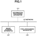
- Fig. 1 illustrates a system configuration according to an exemplary embodiment of the present disclosure.
- the system configuration according to a first exemplary embodiment includes an information processing apparatus 101, an image forming apparatus 102, and a post-processing apparatus 103.
- the information processing apparatus 101, the image forming apparatus 102, and the post-processing apparatus 103 are connected with each other via a network 100.
- the image forming apparatus 102 analyzes print data transmitted from the information processing apparatus 101, converts the print data into a dot image on a per-page basis, and performs printing.
- a print product output from the image forming apparatus 102 may be manually carried to the post-processing apparatus 103 by an operator or by using a belt conveyor (not illustrated).
- the post-processing apparatus 103 is capable of communicating with the image forming apparatus 102 and the information processing apparatus 101 via the network 100.
- the post-processing apparatus 103 processes the transferred print product through cutting, creasing, folding, bookbinding, and perfect binding. It is also possible to perform cutting after book binding by using a plurality of post-processing apparatuses.
- the system configuration includes one information processing apparatus 101, one image forming apparatus 102, and one post-processing apparatus 103
- the system may include any number of apparatuses.
- print products output by a plurality of the image forming apparatuses 102 may be processed by a plurality of the post-processing apparatuses 103.
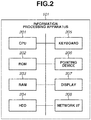
- Fig. 2 illustrates a hardware configuration of the information processing apparatus 101.
- a central processing unit (CPU) 201 reads a control program stored in a read only memory (ROM) 202 and performs various control processing.
- a random access memory (RAM) 203 is used as the main memory of the CPU 201 and as a temporary storage area of a work area.
- a hard disk drive (HDD) 204 stores image data and various programs.
- a keyboard 205 an input apparatus serving as an instruction input unit, is used to input a control command and a text to an application (described below) of the present disclosure.
- a pointing device 206 an input apparatus serving as an instruction input unit like the keyboard 205, issues a control command to an application (described below) of the present disclosure.
- a display 207 an output apparatus serving as a display unit, displays and control display of commands input from the keyboard 205 and the pointing device 206 and the status of an application (described below) of the present disclosure.
- a network I/F 208 connects the information processing apparatus 101 to networks (Local Area Network and the Internet). The information processing apparatus 101 transmits and receives various information to/from other apparatuses on the network by using the network I/F 208.
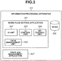
- Fig. 3 illustrates a software configuration of the information processing apparatus 101.
- a work flow setting application 301 is a program module installed in the information processing apparatus 101, loaded into the RAM 203, and executed by the CPU 201.
- a user interface (UI) unit 302 configures a graphical user interface (GUI) and issues an instruction for performing processing for various input operations received from a user.
- a UI control unit 303 generates and displays an assist image (described below) for making it easier for the user to image how each setting is reflected to the final product.
- a work flow control unit 304 performs various edit processing (generation, editing, and registration of a work flow) of the work flow setting application 301.
- a data management unit 305 accesses a work flow database (DB) (described below) and refers to various information related to UIs and work flow control.
- a work flow DB 306 is a database for managing UI and work flow control information (described below).
- the work flow DB 306 may be configured to store information not only in the HDD 204 of the information processing apparatus 101 but also in another information processing apparatus (such as a database server) connected via a network.
- a print job management application 307 is a program module installed in the information processing apparatus 101. The print job management application 307 receives orders for print product generation from the user via an ordering system (not illustrated), acquires work flow information registered by the work flow setting application 301 from the work flow DB 306, and generates a print job corresponding to the order.
- the print job management application 307 transmits the generated print job to a predetermined image forming apparatus 102 and the post-processing apparatus 103.
- the print job management application 307 and the work flow setting application 301 may be configured as one application.
- the print job management application 307 and the work flow setting application 301 may be installed in another information processing apparatus 101.
- the work flow setting application 301 is an application for performing process setting, process order setting, and process setting value setting in pre-print processing (prepress), print processing (press), and post-print processing (postpress).
- Fig. 16 is a flowchart illustrating UI processing of the work flow setting application 301.
- the work flow setting application 301 displays a setting screen.
- the setting screen is used to perform setting to a plurality of setting items for generating a product.
- the plurality of setting items relates to the pre-print processing (prepress), print processing (press), and post-print processing (postpress).
- Fig. 18 illustrates an example of a UI screen for layout setting in the prepress process of the body part.
- An editing target part 1801 indicates that the body is subjected to editing.
- Tab controls 1802 are used to specify an editing target process from prepress (layout), press (printing), and postpress (post-processing) as a setting target process in the work flow.
- the tab controls 1802 indicate a state where prepress is currently being edited.
- Buttons 1803 are used to set various processes. For prepress, buttons for setting the bar code, text, image, register mark, and mark processes are displayed.
- Setting controls 1804 are used to perform advanced layout setting.
- the present exemplary embodiment is on the premise that, when the setting screen is displayed, default values are already input to the setting items of the setting controls 1804.
- the default values of setting items of the setting controls 1804 are acquired from a default value information table determined according to each commercial material (part) illustrated in Fig. 6D .
- the default value information table is stored in the work flow DB 306, read by the data management unit 305, and transferred to the UI unit 302 to be displayed thereon.
- the UI screen includes a preview image 1805.
- step S1602 the work flow setting application 301 determines whether the setting item is selected.
- the work flow setting application 301 determines that the setting item is selected. This determination method is to be considered as an example. Alternatively, when one setting item is selected so that input can be made, the work flow setting application 301 may determine that the setting item is selected. Referring to Fig. 20 , a cursor 2002 is located on OUTPUT PAPER SIZE (WIDTH), for example.
- the work flow setting application 301 determines whether the cursor is located on a setting item based on whether the cursor is located on the input box of the setting item or within a predetermined rectangular range around the setting item.
- step S1602 determines that the setting item is selected (YES in step S1602)
- the processing proceeds to step S1603.
- the work flow setting application 301 does not determine that the setting item is selected (NO in step S1602)
- the processing exits this flowchart.
- step S1603 the work flow setting application 301 displays an assist image for the setting item.
- an image 2001 is an example of an assist image for the output paper size (width). Any assisting method is applicable as long as the user can recognize the current setting position, for example, with an arrow, line, or coloring, like the present exemplary embodiment. Displaying an assist image for the currently selected setting item enables the user to determine the current setting item. Each step for displaying an assist image will be described below with reference to Fig. 17 .
- step S1604 the work flow setting application 301 determines whether the setting value is changed for the currently selected setting item. More specifically, when the user inputs (changes) the setting value, the work flow setting application 301 determines that the setting value is changed.
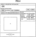
- Fig. 4 illustrates is an example 401 where the output paper size (width) is changed from 329 to 529.
- the changed setting value is stored in the work flow DB 306, the RAM 203, or the HDD 204.
- step S1605 the work flow setting application 301 displays an assist image corresponding to the setting item by using the changed setting value.
- Each step for displaying an assist image will be described below with reference to Fig. 17 .
- the changed setting value of the output paper size (width), 529, is reflected.
- step S1606 the work flow setting application 301 reflects the changed setting value to the preview image.
- the changed setting value of the output paper size (width), 529, is reflected.
- step S1607 the work flow setting application 301 determines whether the setting item is deselected. If the setting item is not focused or not pointed to by the cursor, the work flow setting application 301 determines that the setting item is deselected. If the work flow setting application 301 determines that the setting item is deselected (YES in step S1607), the processing proceeds to step S1608. On the other hand, if the work flow setting application 301 does not determine that the setting item is deselected (NO in step S1607), the processing exits this flowchart.
- step S 1608 the work flow setting application 301 erases the assist image.
- Fig. 4 illustrates an example of a state where the assist image is erased.
- the work flow setting application 301 repeats steps S1602 to S1608 until setting is completed for all setting values. When setting is completed for all setting values, the work flow setting application 301 terminates the processing. Although, in the present exemplary embodiment, the work flow setting application 301 determines that setting is completed for all setting values when the SAVE button is selected, other determination methods may also be employed.
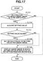
- Fig. 17 is a sub flowchart illustrating processing for displaying an assist image. This sub flowchart corresponds to steps S1603 and S1605 illustrated in Fig. 16 .
- step S1701 the work flow setting application 301 determines whether the currently selected setting item is a setting item for which an assist image is to be displayed. If the work flow setting application 301 determines that the selected setting is a setting item for which an assist image is to be displayed (YES in step S1701), the processing proceeds to step S1702. On the other hand, if the work flow setting application 301 does not determine that the selected setting is not a setting item for which an assist image is to be displayed (NO in step S1701), the processing exit this sub flowchart. The work flow setting application 301 determines whether the currently selected setting is a setting item for which an assist image is to be displayed based on an assist image information table determined according to the commercial materials (parts) illustrated in Fig. 6E .
- the example illustrated in Fig. 6E indicates that the setting items OUTPUT PAPER SIZE (WIDTH), OUTPUT PAPER SIZE (HEIGHT), FINISHING SIZE (WIDTH), and FINISHING SIZE (HEIGHT) are setting items for which assist image is to be displayed.
- the assist image information table is stored in the work flow DB 306, read by the data management unit 305, and transferred to the UI unit 302 to be used for the determination.
- step S1702 the work flow setting application 301 acquires the setting value of the currently selected setting item.
- the cursor 2002 points to the setting value of the setting item OUTPUT PAPER SIZE (WIDTH), 329, and the work flow setting application 301 acquires this setting value.
- step S1703 the work flow setting application 301 determines whether the setting value of the selected setting item is a blank (setting value is absent). If the work flow setting application 301 determines that the setting value is a blank (YES in step S1703), the processing proceeds to step S1704. In step S1704, the work flow setting application 301 sets the default value as the setting value for the assist image. Then, the processing proceeds to step S1705. On the other hand, if the work flow setting application 301 determines that a setting value is present (NO in step S1703), the processing skips step S1704 and proceeds to step S1705.
- step S1705 the work flow setting application 301 displays an assist image in which the setting value is reflected at the setting position on the preview (page preview image).
- the assist image 2001 reflects the output paper size (width), 329 mm.
- the length of the arrow changes according to the setting value of the output paper size (width). Any assisting method is applicable as long as the user can recognize the current setting position, for example, with an arrow, line, or coloring, like the present exemplary embodiment.
- the work flow setting application 301 sets the default value as the setting value of the assist image in step S1704 because the setting value of a blank (setting value is absent) cannot generate an assist image in which the setting value is reflected. Also, by setting the default value, an assist image is displayed even when the setting value is a blank.
- an assist image is displayed separately from the preview image so that the setting item can be identified.
- the assist image 2001 (arrow image) illustrated in Fig. 20 is an example of an assist image.
- the assist image is not limited to an image of an arrow and may be an image of a line, wavy line, mark, or symbol. A different image may be displayed according to the assist position.
- the assist image of the setting item is displayed. This makes it easier for the user to recognize which setting of the product the selected setting item corresponds to.
- Figs. 16 and 17 illustrate examples where, when a setting value is changed, the assist image is corrected according to the changed setting value.
- the first modification will be described below centering on an example where, even when a setting value is changed, an assist image is displayed by using the default setting value.
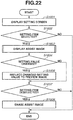
- Fig. 22 is a flowchart illustrating UI processing for inputting a setting value. This flowchart differs from the flowchart illustrated in Fig. 16 in that the processing in step S1605 illustrated in Fig. 16 is absent. More specifically, even when the setting value is changed in step S1604 illustrated in Fig. 22 , the assist image remains unchanged.
- Fig. 19 is a sub flowchart illustrating processing for displaying an assist image. This sub flowchart corresponds to step S1603 illustrated in Fig. 16 .
- step S2301 the work flow setting application 301 acquires the default value of the selected setting item from the default value information table.
- step S2302 the work flow setting application 301 displays an assist image in which the default setting value is reflected at the setting position on the preview.
- an assist image can be displayed while improving the performance of the UI processing.
- Fig. 17 illustrates an example where an assist image displayable in the display area for preview image display is displayed.
- a second modification will be described below centering on an example where an assist image is displayed in an area different from the display area for preview image display.
- a page preview (first preview) is displayed in the display area for preview image display, and an assist image is displayed on an image representing a product from a viewpoint different from the viewpoint of the page.
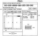
- Fig. 5 illustrates an example of a UI screen for perfect binding setting in the postpress process of the body part.
- An editing target part 501 indicates that the body is subjected to editing.
- Tab controls 502 are used to specify an editing target process from prepress (layout), press (printing), and postpress (post-processing) as a setting target process in the work flow.
- the tab controls 502 indicate a state where postpress is currently being edited.
- Buttons 503 are used to set various processes. For postpress, buttons for setting the folding, cut & crease, saddle stitch, perfect binding, and three-way cutting processes are displayed.
- Setting controls 504 are used to perform advanced perfect binding setting.
- Default values of setting items of the setting controls 1804 are acquired from a default value information table determined according to each commercial material (part) illustrated in Fig. 6A .
- the default value information table is stored in the work flow DB 306, read by the data management unit 305, and transferred to the UI unit 302.
- Fig. 6B illustrates an assist image information table indicating whether each setting item is a setting item for which an assist image is to be displayed. This table is determined according to each commercial material (part).
- Fig. 7 is a sub flowchart illustrating processing for displaying an assist image according to the second modification. Steps other than steps S701 to S703 are similar to steps illustrated in Fig. 17 . Steps similar to steps illustrated in Fig. 17 are assigned the same reference numerals, and redundant descriptions thereof will be omitted.
- step S701 the work flow setting application 301 determines whether the item pointed to and selected by the cursor relates to the normal preview (page preview and first preview).
- the normal preview (page preview) is equivalent to a preview 507 illustrated in Fig. 5 .
- the processing proceeds to step S1705.
- the work flow setting application 301 determines that the selected item does not relate to the normal preview (NO in step S701), the processing proceeds to step S702.
- step S702 the work flow setting application 301 determines whether the item pointed to and selected by the cursor is a setting related to a preview from a different viewpoint.
- a preview 508 illustrated in Fig. 5 is an example of a preview from a different viewpoint (second preview).
- the preview 508 is a preview from a viewpoint at which effects of the settings of the body thickness and gluing thickness are recognizable for a product with the perfect binding setting in the postpress process of the body part.
- a preview from a different viewpoint is prepared for each setting value according to each commercial material (part) and prestored in the work flow DB 306.
- step S702 If the work flow setting application 301 determines that the selected item is a setting related to a preview from a different viewpoint (YES in step S702), the processing proceeds to step S703. On the other hand, if the work flow setting application 301 determines that the selected item is not a setting related to a preview from a different viewpoint (NO in step S702), the processing exits this flowchart.
- the work flow setting application 301 determines whether the item pointed to and selected by the cursor is a setting related to the normal preview or a setting related to a preview from a different viewpoint in steps S701 and S702, based on the preview information table determined according to each commercial material (part) illustrated in Fig. 6C .
- the preview information table is stored in the work flow DB 306, read by the data management unit 305, and transferred to the UI unit 302 to be displayed thereon.
- the preview information table indicates that the body paper size (height) relates only to the normal preview, and the gluing thickness relates only to a preview from a different viewpoint.
- the preview information table also indicates that the body thickness relates to both the normal preview and a preview from a different viewpoint.
- step S703 the work flow setting application 301 displays an assist image in which the setting value is reflected at the setting position on a preview from a different viewpoint.
- an assist image 509 illustrated in Fig. 5 the body paper size (width) 165 mm is reflected.
- the length of the arrow changes reflecting the magnitude of the setting value. Any assisting method is applicable as long as the user can recognize the current setting position, for example, with an arrow, line, or coloring, like the present exemplary embodiment.
- the body paper size (width) relates to both the normal preview (page preview) and a preview from a different viewpoint like the present exemplary embodiment. Therefore, an assist image is displayed in both previews as the assist images 506 and 509.
- some setting items relate to either one of the normal preview and a preview from a different viewpoint.
- the gluing thickness is one of such setting items.
- Fig. 9 illustrates a screen displayed when the setting item PASTING THICKNESS is selected.
- the gluing thickness is set by the setting item at a cursor 901.
- Fig. 9 illustrates a UI at the time of perfect binding setting in the postpress process of the body part.
- the gluing thickness does not appear in the normal preview.
- the gluing thickness can be displayed like an assist image 902, enabling the user to recognize how the setting value is reflected. Adding an assist image from a different viewpoint in this way makes it easier for the user to image how the setting value is reflected to a product.
- a register mark position is a setting item which does not appear in a preview from a different viewpoint but appears only in the normal preview. This mark position indicates the position for cutting with a setting value (not illustrated) set in the prepress process.
- a register mark appears like an image 903 in the normal preview enabling the user to image a product but does not appear in a preview from a different viewpoint.
- an assist image is displayed in a preview image from a different viewpoint.
- an assist image may be displayed in an icon image from a different viewpoint, instead of a preview image from a different viewpoint. More specifically, if the product is a book, an assist image is added to the book to enable the user to grasp the setting position to the product. In addition, if the setting value cannot be expressed in the normal preview image, an assist image may be displayed only in an image from a different viewpoint.
- the final finishing size (width) is used as a setting item.
- the final finishing size (width) is a setting item related to the normal preview and also is a setting item related to a preview from a different viewpoint.
- Fig. 14 illustrates an example of a UI screen of saddle stitch setting (right binding) in the postpress process of the body part.
- Setting controls 1401 are used to perform advanced saddle stitch setting.
- a button 1402 indicates that the right binding setting is selected as the binding direction.
- a cursor 1403 is located on the setting item FINAL FINISHING SIZE (WIDTH).
- An image 1404 is an example of a normal preview. The right binding being set, the left page is the first page (page 1) and the right page is the last page (page 200 in this example).
- An image 1405 is an example of an assist image on the normal preview of the final finishing size (width).
- An image 1406 is an example of a preview from a different viewpoint, and an image 1407 is an example of an assist image on the preview from a different viewpoint for the final finishing size (width).
- Fig. 15 illustrates an example of a UI screen of saddle stitch setting (left binding) in the postpress process of the body part.
- a button 1501 indicates that the left binding setting is selected as the binding direction.
- a cursor 1502 is located on the setting item FINAL FINISHING SIZE (WIDTH).
- An image 1503 is an example of a normal preview. The left binding being set, the right page is the first page (page 1) and the left page is the last page (page 200 in this example) in contrary to the case of the right binding (the preview 1404).
- An image 1504 is an example of an assist image on the normal preview of the final finishing size (width).
- An image 1505 is an example of a preview from a different viewpoint for the left binding in a different direction from the right binding (the image 1407).
- An image 1506 is an example of an assist image on a preview from a different viewpoint with the final finishing size (width).
- a preview from a different viewpoint makes it possible to display a preview closer to the product according to a setting, enabling the user to image how the setting is set to the product.
- a preview from a different viewpoint is prepared for each setting value according to each commercial material (part) and prestored in the work flow DB 306.
- the third modification will be described below centering on processing for displaying a preview of a plurality of parts related to the commercial material type and displaying an assist image of each setting.
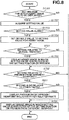
- Fig. 8 is a sub flowchart illustrating processing for displaying an assist image according to the third modification. Steps other than steps S801 and S802 are similar to steps illustrated in Figs. 7 and 17 . Steps similar to steps illustrated in Figs. 7 and 17 are assigned the same reference numerals, and redundant descriptions thereof will be omitted.
- step S801 the work flow setting application 301 determines whether the setting also relates to other parts.
- the processing proceeds to step S802.
- the work flow setting application 301 determines that the setting does not relate to other parts (NO in step S801), the processing proceeds to step S703.
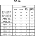
- Fig. 10 illustrates the related part information table for each setting value of folding setting in the postpress process of the jacket part and book commercial materials.
- BASE POINT OF CUT BLOCK: X1 relates no other parts
- CREASE 1: X2 relates to the body, cover, title page, and book band parts.
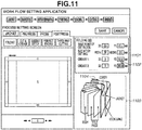
- Fig. 11 illustrates an example case where the setting pointed to by the cursor also relates to other parts.
- a setting control 1101 is used to perform advanced folding setting.
- a cursor 1102 is located on CREASE 1: Y2 (FOLDING).
- Y2 of crease 1 indicates the folding width of the jacket. Collectively displaying related parts such as the body, title page, cover, and book band in this way makes it easier for the user to image the effect of the setting.
- the related part information table illustrated in Fig. 10 describes that Y2 of crease 1 relates to the body, cover, title page, and book band parts.
- An image 1103 is an example of an assist image where the related body, title page, cover, and book band parts are displayed together with the jacket part.
- An image 1104 is an assist image of Y2 of crease 1 which enables the user to image the effect of the setting on the final product.
- An image 1202 illustrated in Fig. 12 is an example of an assist image where only the jacket part is displayed and related parts are not in a preview from a different viewpoint. With this assist image, the final product is hard to image.
- Fig. 13 illustrates an example where the cursor is located on HEIGHT for SIZE AFTER CUTTING in a case where the setting does not relate to other parts.
- An image 1303 indicates an assist image of only the jacket part in a preview from a different viewpoint. For the height of the size after cutting, only a preview of the jacket part from a different viewpoint enables the user to easily image how the setting is reflected to the final product.
- the preview may constantly display both the target part and related parts.
- Embodiment(s) can also be realized by a computer of a system or apparatus that reads out and executes computer executable instructions (e.g., one or more programs) recorded on a storage medium (which may also be referred to more fully as a 'non-transitory computer-readable storage medium') to perform the functions of one or more of the above-described embodiment(s) and/or that includes one or more circuits (e.g., application specific integrated circuit (ASIC)) for performing the functions of one or more of the above-described embodiment(s), and by a method performed by the computer of the system or apparatus by, for example, reading out and executing the computer executable instructions from the storage medium to perform the functions of one or more of the above-described embodiment(s) and/or controlling the one or more circuits to perform the functions of one or more of the above-described embodiment(s).
- computer executable instructions e.g., one or more programs
- a storage medium which may also be referred to more fully as a 'n
- the computer may comprise one or more processors (e.g., central processing unit (CPU), micro processing unit (MPU)) and may include a network of separate computers or separate processors to read out and execute the computer executable instructions.
- the computer executable instructions may be provided to the computer, for example, from a network or the storage medium.
- the storage medium may include, for example, one or more of a hard disk, a random-access memory (RAM), a read only memory (ROM), a storage of distributed computing systems, an optical disk (such as a compact disc (CD), digital versatile disc (DVD), or Blu-ray Disc (BD)TM), a flash memory device, a memory card, and the like. While the present disclosure has been described with reference to exemplary embodiments, it is to be understood that the invention is not limited to the disclosed exemplary embodiments. The scope of the following claims is to be accorded the broadest interpretation so as to encompass all such modifications and equivalent structures and functions.
Landscapes
- Engineering & Computer Science (AREA)
- Theoretical Computer Science (AREA)
- General Engineering & Computer Science (AREA)
- Human Computer Interaction (AREA)
- Physics & Mathematics (AREA)
- General Physics & Mathematics (AREA)
- Quality & Reliability (AREA)
- User Interface Of Digital Computer (AREA)
- Accessory Devices And Overall Control Thereof (AREA)
Abstract
Description
- The present disclosure relates to settings in commercial printing.
- In commercial printing, a work flow is generated by assigning parts (cover, body, title page, book band, etc.) required to produce a commercial material (book, flier, card, etc.) and processes (layout, bar code attachment, printing, folding, perfect binding, three-way cutting, etc.) required for each part. An ordered job is automatically processed based on the generated work flow. Commercial material generation software discussed in Japanese Patent Application Laid-Open No.
2014-191388 - Although the conventional commercial material generation software discussed in Japanese Patent Application Laid-Open No.
2014-191388 - In consideration of the above-discussed points, the present disclosure features, among other things, offering a technique for making it easier for a user to recognize which setting item is being set for a product when performing setting a plurality of setting items for generating a product.
- According to a first aspect of the present invention, there is provided an information processing apparatus as specified in
claims 1 to 7. According to a second aspect of the present invention, there is provided a control method as specified in claims 8 to 14. According to a third aspect of the present invention, there is provided a computer-readable medium as specified in claim 15. - Further features of the present disclosure will become apparent from the following description of exemplary embodiments with reference to the attached drawings.
-
-
Fig. 1 illustrates a system configuration of the present disclosure. -
Fig. 2 illustrates a hardware configuration of an information processing apparatus of the present disclosure. -
Fig. 3 illustrates a software configuration of the present disclosure. -
Fig. 4 illustrates an example of a setting screen. -
Fig. 5 illustrates an example of a work flow process setting screen. -
Figs. 6A, 6B, 6C, 6D, and 6E illustrate examples of information tables. -
Fig. 7 is a sub flowchart illustrating processing for displaying an assist image according to a second modification. -
Fig. 8 is a sub flowchart illustrating processing for displaying an assist image according to a third modification. -
Fig. 9 illustrates an example of a user interface (UI) at the time of perfect binding setting in a postpress process. -
Fig. 10 illustrates an example of a related parts information table. -
Fig. 11 illustrates an example of a postpress process setting screen. -
Fig. 12 illustrates another example of the postpress process setting screen. -
Fig. 13 illustrates still another example of the postpress process setting screen. -
Fig. 14 illustrates an example of a UI screen for right binding of a saddle stitch setting in the postpress process. -
Fig. 15 illustrates an example of a UI screen for left binding of a saddle stitch setting in the postpress process. -
Fig. 16 is a flowchart illustrating UI processing related to work flow generation. -
Fig. 17 is a sub flowchart illustrating processing for displaying an assist image. -
Fig. 18 illustrates an example of a UI for layout setting in a prepress process. -
Fig. 19 is a sub flowchart illustrating processing for displaying an assist image according to a first modification. -
Fig. 20 illustrates an example of a setting screen. -
Fig. 21 illustrates another example of the setting screen. -
Fig. 22 is a flowchart illustrating UI processing related to work flow generation according to the first modification. - Exemplary embodiments of the present disclosure will be described below with reference to the accompanying drawings.
-
Fig. 1 illustrates a system configuration according to an exemplary embodiment of the present disclosure. The system configuration according to a first exemplary embodiment includes aninformation processing apparatus 101, animage forming apparatus 102, and apost-processing apparatus 103. Theinformation processing apparatus 101, theimage forming apparatus 102, and thepost-processing apparatus 103 are connected with each other via anetwork 100. Theimage forming apparatus 102 analyzes print data transmitted from theinformation processing apparatus 101, converts the print data into a dot image on a per-page basis, and performs printing. A print product output from theimage forming apparatus 102 may be manually carried to thepost-processing apparatus 103 by an operator or by using a belt conveyor (not illustrated). Thepost-processing apparatus 103 is capable of communicating with theimage forming apparatus 102 and theinformation processing apparatus 101 via thenetwork 100. Thepost-processing apparatus 103 processes the transferred print product through cutting, creasing, folding, bookbinding, and perfect binding. It is also possible to perform cutting after book binding by using a plurality of post-processing apparatuses. Although, inFig. 1 , the system configuration includes oneinformation processing apparatus 101, oneimage forming apparatus 102, and onepost-processing apparatus 103, the system may include any number of apparatuses. For example, print products output by a plurality of theimage forming apparatuses 102 may be processed by a plurality of thepost-processing apparatuses 103. -
Fig. 2 illustrates a hardware configuration of theinformation processing apparatus 101. A central processing unit (CPU) 201 reads a control program stored in a read only memory (ROM) 202 and performs various control processing. A random access memory (RAM) 203 is used as the main memory of theCPU 201 and as a temporary storage area of a work area. A hard disk drive (HDD) 204 stores image data and various programs. Akeyboard 205, an input apparatus serving as an instruction input unit, is used to input a control command and a text to an application (described below) of the present disclosure. Apointing device 206, an input apparatus serving as an instruction input unit like thekeyboard 205, issues a control command to an application (described below) of the present disclosure. Adisplay 207, an output apparatus serving as a display unit, displays and control display of commands input from thekeyboard 205 and thepointing device 206 and the status of an application (described below) of the present disclosure. A network I/F 208 connects theinformation processing apparatus 101 to networks (Local Area Network and the Internet). Theinformation processing apparatus 101 transmits and receives various information to/from other apparatuses on the network by using the network I/F 208. -
Fig. 3 illustrates a software configuration of theinformation processing apparatus 101. A workflow setting application 301 is a program module installed in theinformation processing apparatus 101, loaded into theRAM 203, and executed by theCPU 201. A user interface (UI)unit 302 configures a graphical user interface (GUI) and issues an instruction for performing processing for various input operations received from a user. AUI control unit 303 generates and displays an assist image (described below) for making it easier for the user to image how each setting is reflected to the final product. A workflow control unit 304 performs various edit processing (generation, editing, and registration of a work flow) of the workflow setting application 301. Adata management unit 305 accesses a work flow database (DB) (described below) and refers to various information related to UIs and work flow control. Awork flow DB 306 is a database for managing UI and work flow control information (described below). Thework flow DB 306 may be configured to store information not only in theHDD 204 of theinformation processing apparatus 101 but also in another information processing apparatus (such as a database server) connected via a network. A printjob management application 307 is a program module installed in theinformation processing apparatus 101. The printjob management application 307 receives orders for print product generation from the user via an ordering system (not illustrated), acquires work flow information registered by the workflow setting application 301 from thework flow DB 306, and generates a print job corresponding to the order. Then, the printjob management application 307 transmits the generated print job to a predeterminedimage forming apparatus 102 and thepost-processing apparatus 103. The printjob management application 307 and the workflow setting application 301 may be configured as one application. The printjob management application 307 and the workflow setting application 301 may be installed in anotherinformation processing apparatus 101. The workflow setting application 301 is an application for performing process setting, process order setting, and process setting value setting in pre-print processing (prepress), print processing (press), and post-print processing (postpress). -
Fig. 16 is a flowchart illustrating UI processing of the workflow setting application 301. - In step S1601, the work
flow setting application 301 displays a setting screen. The setting screen is used to perform setting to a plurality of setting items for generating a product. The plurality of setting items relates to the pre-print processing (prepress), print processing (press), and post-print processing (postpress).Fig. 18 illustrates an example of a UI screen for layout setting in the prepress process of the body part. Anediting target part 1801 indicates that the body is subjected to editing. Tab controls 1802 are used to specify an editing target process from prepress (layout), press (printing), and postpress (post-processing) as a setting target process in the work flow. The tab controls 1802 indicate a state where prepress is currently being edited.Buttons 1803 are used to set various processes. For prepress, buttons for setting the bar code, text, image, register mark, and mark processes are displayed. Setting controls 1804 are used to perform advanced layout setting. - The present exemplary embodiment is on the premise that, when the setting screen is displayed, default values are already input to the setting items of the setting controls 1804. The default values of setting items of the setting controls 1804 are acquired from a default value information table determined according to each commercial material (part) illustrated in
Fig. 6D . The default value information table is stored in thework flow DB 306, read by thedata management unit 305, and transferred to theUI unit 302 to be displayed thereon. The UI screen includes apreview image 1805. - In step S1602, the work
flow setting application 301 determines whether the setting item is selected. When the cursor is located in a predetermined range of a setting item or when a setting item is focused, the workflow setting application 301 determines that the setting item is selected. This determination method is to be considered as an example. Alternatively, when one setting item is selected so that input can be made, the workflow setting application 301 may determine that the setting item is selected. Referring toFig. 20 , acursor 2002 is located on OUTPUT PAPER SIZE (WIDTH), for example. The workflow setting application 301 determines whether the cursor is located on a setting item based on whether the cursor is located on the input box of the setting item or within a predetermined rectangular range around the setting item. If the workflow setting application 301 determines that the setting item is selected (YES in step S1602), the processing proceeds to step S1603. On the other hand, if the workflow setting application 301 does not determine that the setting item is selected (NO in step S1602), the processing exits this flowchart. - In step S1603, the work
flow setting application 301 displays an assist image for the setting item. Referring toFig. 20 , for example, animage 2001 is an example of an assist image for the output paper size (width). Any assisting method is applicable as long as the user can recognize the current setting position, for example, with an arrow, line, or coloring, like the present exemplary embodiment. Displaying an assist image for the currently selected setting item enables the user to determine the current setting item. Each step for displaying an assist image will be described below with reference toFig. 17 . - In step S1604, the work
flow setting application 301 determines whether the setting value is changed for the currently selected setting item. More specifically, when the user inputs (changes) the setting value, the workflow setting application 301 determines that the setting value is changed.Fig. 4 illustrates is an example 401 where the output paper size (width) is changed from 329 to 529. The changed setting value is stored in thework flow DB 306, theRAM 203, or theHDD 204. - In step S1605, the work
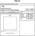
flow setting application 301 displays an assist image corresponding to the setting item by using the changed setting value. Each step for displaying an assist image will be described below with reference toFig. 17 . In anassist image 2101 illustrated inFig. 21 , the changed setting value of the output paper size (width), 529, is reflected. - In step S1606, the work
flow setting application 301 reflects the changed setting value to the preview image. In apreview 2102 illustrated inFig. 21 , the changed setting value of the output paper size (width), 529, is reflected. - In step S1607, the work
flow setting application 301 determines whether the setting item is deselected. If the setting item is not focused or not pointed to by the cursor, the workflow setting application 301 determines that the setting item is deselected. If the workflow setting application 301 determines that the setting item is deselected (YES in step S1607), the processing proceeds to step S1608. On the other hand, if the workflow setting application 301 does not determine that the setting item is deselected (NO in step S1607), the processing exits this flowchart. - In step S 1608, the work
flow setting application 301 erases the assist image.Fig. 4 illustrates an example of a state where the assist image is erased. - The work
flow setting application 301 repeats steps S1602 to S1608 until setting is completed for all setting values. When setting is completed for all setting values, the workflow setting application 301 terminates the processing. Although, in the present exemplary embodiment, the workflow setting application 301 determines that setting is completed for all setting values when the SAVE button is selected, other determination methods may also be employed. -
Fig. 17 is a sub flowchart illustrating processing for displaying an assist image. This sub flowchart corresponds to steps S1603 and S1605 illustrated inFig. 16 . - In step S1701, the work
flow setting application 301 determines whether the currently selected setting item is a setting item for which an assist image is to be displayed. If the workflow setting application 301 determines that the selected setting is a setting item for which an assist image is to be displayed (YES in step S1701), the processing proceeds to step S1702. On the other hand, if the workflow setting application 301 does not determine that the selected setting is not a setting item for which an assist image is to be displayed (NO in step S1701), the processing exit this sub flowchart. The workflow setting application 301 determines whether the currently selected setting is a setting item for which an assist image is to be displayed based on an assist image information table determined according to the commercial materials (parts) illustrated inFig. 6E . The example illustrated inFig. 6E indicates that the setting items OUTPUT PAPER SIZE (WIDTH), OUTPUT PAPER SIZE (HEIGHT), FINISHING SIZE (WIDTH), and FINISHING SIZE (HEIGHT) are setting items for which assist image is to be displayed. The assist image information table is stored in thework flow DB 306, read by thedata management unit 305, and transferred to theUI unit 302 to be used for the determination. - In step S1702, the work
flow setting application 301 acquires the setting value of the currently selected setting item. Referring toFig. 20 , thecursor 2002 points to the setting value of the setting item OUTPUT PAPER SIZE (WIDTH), 329, and the workflow setting application 301 acquires this setting value. - In step S1703, the work
flow setting application 301 determines whether the setting value of the selected setting item is a blank (setting value is absent). If the workflow setting application 301 determines that the setting value is a blank (YES in step S1703), the processing proceeds to step S1704. In step S1704, the workflow setting application 301 sets the default value as the setting value for the assist image. Then, the processing proceeds to step S1705. On the other hand, if the workflow setting application 301 determines that a setting value is present (NO in step S1703), the processing skips step S1704 and proceeds to step S1705. - In step S1705, the work
flow setting application 301 displays an assist image in which the setting value is reflected at the setting position on the preview (page preview image). Referring toFig. 20 , theassist image 2001 reflects the output paper size (width), 329 mm. The length of the arrow changes according to the setting value of the output paper size (width). Any assisting method is applicable as long as the user can recognize the current setting position, for example, with an arrow, line, or coloring, like the present exemplary embodiment. The workflow setting application 301 sets the default value as the setting value of the assist image in step S1704 because the setting value of a blank (setting value is absent) cannot generate an assist image in which the setting value is reflected. Also, by setting the default value, an assist image is displayed even when the setting value is a blank. - According to the present exemplary embodiment, an assist image is displayed separately from the preview image so that the setting item can be identified. The assist image 2001 (arrow image) illustrated in
Fig. 20 is an example of an assist image. However, the assist image is not limited to an image of an arrow and may be an image of a line, wavy line, mark, or symbol. A different image may be displayed according to the assist position. - When the user inputs a setting value, the assist image of the setting item is displayed. This makes it easier for the user to recognize which setting of the product the selected setting item corresponds to.
- A first modification of the first exemplary embodiment will be described below.
-
Figs. 16 and17 illustrate examples where, when a setting value is changed, the assist image is corrected according to the changed setting value. The first modification will be described below centering on an example where, even when a setting value is changed, an assist image is displayed by using the default setting value. -
Fig. 22 is a flowchart illustrating UI processing for inputting a setting value. This flowchart differs from the flowchart illustrated inFig. 16 in that the processing in step S1605 illustrated inFig. 16 is absent. More specifically, even when the setting value is changed in step S1604 illustrated inFig. 22 , the assist image remains unchanged. -
Fig. 19 is a sub flowchart illustrating processing for displaying an assist image. This sub flowchart corresponds to step S1603 illustrated inFig. 16 . - In step S2301, the work
flow setting application 301 acquires the default value of the selected setting item from the default value information table. In step S2302, the workflow setting application 301 displays an assist image in which the default setting value is reflected at the setting position on the preview. - According to a first modification, since an assist image is not corrected and displayed according to the changed setting value, an assist image can be displayed while improving the performance of the UI processing.
- A second modification of the first exemplary embodiment will be described below.
-
Fig. 17 illustrates an example where an assist image displayable in the display area for preview image display is displayed. A second modification will be described below centering on an example where an assist image is displayed in an area different from the display area for preview image display. According to the present modification, a page preview (first preview) is displayed in the display area for preview image display, and an assist image is displayed on an image representing a product from a viewpoint different from the viewpoint of the page. -
Fig. 5 illustrates an example of a UI screen for perfect binding setting in the postpress process of the body part. An editing target part 501 indicates that the body is subjected to editing. Tab controls 502 are used to specify an editing target process from prepress (layout), press (printing), and postpress (post-processing) as a setting target process in the work flow. The tab controls 502 indicate a state where postpress is currently being edited.Buttons 503 are used to set various processes. For postpress, buttons for setting the folding, cut & crease, saddle stitch, perfect binding, and three-way cutting processes are displayed. Setting controls 504 are used to perform advanced perfect binding setting. Default values of setting items of the setting controls 1804 are acquired from a default value information table determined according to each commercial material (part) illustrated inFig. 6A . The default value information table is stored in thework flow DB 306, read by thedata management unit 305, and transferred to theUI unit 302.Fig. 6B illustrates an assist image information table indicating whether each setting item is a setting item for which an assist image is to be displayed. This table is determined according to each commercial material (part). -
Fig. 7 is a sub flowchart illustrating processing for displaying an assist image according to the second modification. Steps other than steps S701 to S703 are similar to steps illustrated inFig. 17 . Steps similar to steps illustrated inFig. 17 are assigned the same reference numerals, and redundant descriptions thereof will be omitted. - In step S701, the work
flow setting application 301 determines whether the item pointed to and selected by the cursor relates to the normal preview (page preview and first preview). The normal preview (page preview) is equivalent to apreview 507 illustrated inFig. 5 . When the workflow setting application 301 determines that the selected item relates to the normal preview (YES in step S701), the processing proceeds to step S1705. On the other hand, when the workflow setting application 301 determines that the selected item does not relate to the normal preview (NO in step S701), the processing proceeds to step S702. - In step S702, the work
flow setting application 301 determines whether the item pointed to and selected by the cursor is a setting related to a preview from a different viewpoint. Apreview 508 illustrated inFig. 5 is an example of a preview from a different viewpoint (second preview). For example, thepreview 508 is a preview from a viewpoint at which effects of the settings of the body thickness and gluing thickness are recognizable for a product with the perfect binding setting in the postpress process of the body part. A preview from a different viewpoint is prepared for each setting value according to each commercial material (part) and prestored in thework flow DB 306. If the workflow setting application 301 determines that the selected item is a setting related to a preview from a different viewpoint (YES in step S702), the processing proceeds to step S703. On the other hand, if the workflow setting application 301 determines that the selected item is not a setting related to a preview from a different viewpoint (NO in step S702), the processing exits this flowchart. - The work
flow setting application 301 determines whether the item pointed to and selected by the cursor is a setting related to the normal preview or a setting related to a preview from a different viewpoint in steps S701 and S702, based on the preview information table determined according to each commercial material (part) illustrated inFig. 6C . The preview information table is stored in thework flow DB 306, read by thedata management unit 305, and transferred to theUI unit 302 to be displayed thereon. Referring toFig. 6C , the preview information table indicates that the body paper size (height) relates only to the normal preview, and the gluing thickness relates only to a preview from a different viewpoint. The preview information table also indicates that the body thickness relates to both the normal preview and a preview from a different viewpoint. - In step S703, the work
flow setting application 301 displays an assist image in which the setting value is reflected at the setting position on a preview from a different viewpoint. In anassist image 509 illustrated inFig. 5 , the body paper size (width) 165 mm is reflected. The length of the arrow changes reflecting the magnitude of the setting value. Any assisting method is applicable as long as the user can recognize the current setting position, for example, with an arrow, line, or coloring, like the present exemplary embodiment. - The body paper size (width) relates to both the normal preview (page preview) and a preview from a different viewpoint like the present exemplary embodiment. Therefore, an assist image is displayed in both previews as the assist
images - In contrast, some setting items relate to either one of the normal preview and a preview from a different viewpoint.
- For example, the gluing thickness is one of such setting items.
-
Fig. 9 illustrates a screen displayed when the setting item PASTING THICKNESS is selected. Referring toFig. 9 , the gluing thickness is set by the setting item at acursor 901.Fig. 9 illustrates a UI at the time of perfect binding setting in the postpress process of the body part. The gluing thickness does not appear in the normal preview. In a preview from a different viewpoint, the gluing thickness can be displayed like anassist image 902, enabling the user to recognize how the setting value is reflected. Adding an assist image from a different viewpoint in this way makes it easier for the user to image how the setting value is reflected to a product. - A register mark position is a setting item which does not appear in a preview from a different viewpoint but appears only in the normal preview. This mark position indicates the position for cutting with a setting value (not illustrated) set in the prepress process. A register mark appears like an
image 903 in the normal preview enabling the user to image a product but does not appear in a preview from a different viewpoint. - In the above-described example, an assist image is displayed in a preview image from a different viewpoint. Alternatively, an assist image may be displayed in an icon image from a different viewpoint, instead of a preview image from a different viewpoint. More specifically, if the product is a book, an assist image is added to the book to enable the user to grasp the setting position to the product. In addition, if the setting value cannot be expressed in the normal preview image, an assist image may be displayed only in an image from a different viewpoint.
- In this way, by displaying an image from a different viewpoint in addition to the normal preview image and displaying an assist image with the setting value reflected in both images, it becomes easier for the user to recognize how the setting value is reflected to the final product.
- Other examples of previews from a different viewpoint are illustrated in
Figs. 14 and15 . In this example, the final finishing size (width) is used as a setting item. The final finishing size (width) is a setting item related to the normal preview and also is a setting item related to a preview from a different viewpoint. -
Fig. 14 illustrates an example of a UI screen of saddle stitch setting (right binding) in the postpress process of the body part. Setting controls 1401 are used to perform advanced saddle stitch setting. Abutton 1402 indicates that the right binding setting is selected as the binding direction. Acursor 1403 is located on the setting item FINAL FINISHING SIZE (WIDTH). - An
image 1404 is an example of a normal preview. The right binding being set, the left page is the first page (page 1) and the right page is the last page (page 200 in this example). Animage 1405 is an example of an assist image on the normal preview of the final finishing size (width). Animage 1406 is an example of a preview from a different viewpoint, and animage 1407 is an example of an assist image on the preview from a different viewpoint for the final finishing size (width). -
Fig. 15 illustrates an example of a UI screen of saddle stitch setting (left binding) in the postpress process of the body part. Abutton 1501 indicates that the left binding setting is selected as the binding direction. Acursor 1502 is located on the setting item FINAL FINISHING SIZE (WIDTH). Animage 1503 is an example of a normal preview. The left binding being set, the right page is the first page (page 1) and the left page is the last page (page 200 in this example) in contrary to the case of the right binding (the preview 1404). Animage 1504 is an example of an assist image on the normal preview of the final finishing size (width). Animage 1505 is an example of a preview from a different viewpoint for the left binding in a different direction from the right binding (the image 1407). Animage 1506 is an example of an assist image on a preview from a different viewpoint with the final finishing size (width). A preview from a different viewpoint makes it possible to display a preview closer to the product according to a setting, enabling the user to image how the setting is set to the product. A preview from a different viewpoint is prepared for each setting value according to each commercial material (part) and prestored in thework flow DB 306. - A third modification of the first exemplary embodiment will be described below.
- The third modification will be described below centering on processing for displaying a preview of a plurality of parts related to the commercial material type and displaying an assist image of each setting.
-
Fig. 8 is a sub flowchart illustrating processing for displaying an assist image according to the third modification. Steps other than steps S801 and S802 are similar to steps illustrated inFigs. 7 and17 . Steps similar to steps illustrated inFigs. 7 and17 are assigned the same reference numerals, and redundant descriptions thereof will be omitted. - In step S801, the work
flow setting application 301 determines whether the setting also relates to other parts. When the workflow setting application 301 determines that the setting also relates to other parts (YES in step S801), the processing proceeds to step S802. On the other hand, the workflow setting application 301 determines that the setting does not relate to other parts (NO in step S801), the processing proceeds to step S703. - Determination as to whether the setting relates to other parts can be determined based on the related part information table determined according to the setting for each part illustrated in
Fig. 10. Fig. 10 illustrates the related part information table for each setting value of folding setting in the postpress process of the jacket part and book commercial materials. For example, BASE POINT OF CUT BLOCK: X1 relates no other parts, and CREASE 1: X2 relates to the body, cover, title page, and book band parts. -
Fig. 11 illustrates an example case where the setting pointed to by the cursor also relates to other parts. In the folding setting in the postpress process of the jacket part, asetting control 1101 is used to perform advanced folding setting. Acursor 1102 is located on CREASE 1: Y2 (FOLDING). - Y2 of
crease 1 indicates the folding width of the jacket. Collectively displaying related parts such as the body, title page, cover, and book band in this way makes it easier for the user to image the effect of the setting. The related part information table illustrated inFig. 10 describes that Y2 ofcrease 1 relates to the body, cover, title page, and book band parts. Animage 1103 is an example of an assist image where the related body, title page, cover, and book band parts are displayed together with the jacket part. Animage 1104 is an assist image of Y2 ofcrease 1 which enables the user to image the effect of the setting on the final product. - An
image 1202 illustrated inFig. 12 is an example of an assist image where only the jacket part is displayed and related parts are not in a preview from a different viewpoint. With this assist image, the final product is hard to image. -
Fig. 13 illustrates an example where the cursor is located on HEIGHT for SIZE AFTER CUTTING in a case where the setting does not relate to other parts. Animage 1303 indicates an assist image of only the jacket part in a preview from a different viewpoint. For the height of the size after cutting, only a preview of the jacket part from a different viewpoint enables the user to easily image how the setting is reflected to the final product. - Although, according to the present exemplary embodiment, a preview of the target part from a different viewpoint is displayed with or without other related parts, the preview may constantly display both the target part and related parts.
- According to the above-described exemplary embodiment, when inputting a setting value in a preview of the setting screen, it is made easier for the user to recognize which setting value corresponds to which setting in the product, by providing an assist image for the setting position.
- While the present disclosure has been described with reference to exemplary embodiments, it is to be understood that the invention is not limited to the disclosed exemplary embodiments. The scope of the following claims is to be accorded the broadest interpretation so as to encompass all such modifications and equivalent structures and functions.
- Embodiment(s) can also be realized by a computer of a system or apparatus that reads out and executes computer executable instructions (e.g., one or more programs) recorded on a storage medium (which may also be referred to more fully as a 'non-transitory computer-readable storage medium') to perform the functions of one or more of the above-described embodiment(s) and/or that includes one or more circuits (e.g., application specific integrated circuit (ASIC)) for performing the functions of one or more of the above-described embodiment(s), and by a method performed by the computer of the system or apparatus by, for example, reading out and executing the computer executable instructions from the storage medium to perform the functions of one or more of the above-described embodiment(s) and/or controlling the one or more circuits to perform the functions of one or more of the above-described embodiment(s). The computer may comprise one or more processors (e.g., central processing unit (CPU), micro processing unit (MPU)) and may include a network of separate computers or separate processors to read out and execute the computer executable instructions. The computer executable instructions may be provided to the computer, for example, from a network or the storage medium. The storage medium may include, for example, one or more of a hard disk, a random-access memory (RAM), a read only memory (ROM), a storage of distributed computing systems, an optical disk (such as a compact disc (CD), digital versatile disc (DVD), or Blu-ray Disc (BD)™), a flash memory device, a memory card, and the like. While the present disclosure has been described with reference to exemplary embodiments, it is to be understood that the invention is not limited to the disclosed exemplary embodiments. The scope of the following claims is to be accorded the broadest interpretation so as to encompass all such modifications and equivalent structures and functions.
Claims (15)
- An information processing apparatus comprising:display control means for displaying a setting screen for performing setting for a plurality of setting items for generating a product; anddetermination means for determining whether a setting item of the plurality of setting items is selected in the setting screen,wherein, in the setting screen, in a case where the setting item is determined to be selected, an image related to the setting item selected is displayed, and in a case where the setting item is determined to be not selected, the image related to the setting item is not displayed.
- The information processing apparatus according to claim 1,
wherein the setting screen displays an image related to a product, and
wherein the image related to the setting item is displayed on the image related to the product. - The information processing apparatus according to claim 1,
wherein the setting screen displays a page preview image of a product, and
wherein the image related to the setting item is displayed on the page preview image. - The information processing apparatus according to claim 1, wherein the determination means determines that the setting item is selected in a case where a cursor is located within a predetermined range of the setting item.
- The information processing apparatus according to claim 1, wherein the determination means determines that the setting item is selected in a case where the setting item is focused.
- The information processing apparatus according to claim 1,
wherein, in a case where the determination means determines that the setting item is selected, the determination means further determines whether the selected setting item is one for which an image related to the setting item is to be displayed,
wherein, in a case where the selected setting item is determined to be one for which an image related to the setting item is set to be displayed, the image related to the selected setting item and set to be displayed is displayed, and
wherein, in a case where the selected setting item is determined not to be one for which the image related to the setting item is set to be displayed, the image related to the setting item and not set to be displayed is not displayed. - The information processing apparatus according to claim 1, wherein the plurality of setting items includes setting items related to any one of pre-print processing, print processing, and post-print processing.
- A method for controlling an information processing apparatus, the method comprising:displaying a setting screen for performing setting for a plurality of setting items for generating a product; anddetermining whether a setting item of the plurality of setting items is selected in the setting screen,wherein, in the setting screen, in a case where the setting item is determined to be selected, an image related to the setting item selected is displayed, and in a case where the setting item is determined to be not selected, the image related to the setting item is not displayed.
- The method for controlling an information processing apparatus according to claim 8,
wherein the setting screen displays an image related to a product, and
wherein the image related to the setting item is displayed on the image related to the product. - The method for controlling an information processing apparatus according to claim 8,
wherein the setting screen displays a page preview image of a product, and
wherein the image related to the setting item is displayed on the page preview image. - The method for controlling an information processing apparatus according to claim 8, wherein, in the determining, the setting item is determined to be selected in a case where a cursor is located within a predetermined range of the setting item.
- The method for controlling an information processing apparatus according to claim 8, wherein, in the determining, the setting item is determined to be selected in a case where the setting item is focused.
- The method for controlling an information processing apparatus according to claim 8,
wherein, in the determining, in a case where the setting item is determined to be selected, whether the selected setting item is one for which an image related to the setting item is set to be displayed is further determined,
wherein, in a case where the selected setting item is determined to be one for which the image related to the setting item is set to be displayed, the image related to the selected setting item and set to be displayed is displayed, and
wherein, in a case where the selected setting item is determined not to be one for which the image related to the setting item is set to be displayed, the image related to the setting item and not set to be displayed is not displayed. - The method for controlling an information processing apparatus according to claim 8, wherein the plurality of setting items includes setting items related to any one of pre-print processing, print processing, and post-print processing.
- A non-transitory computer-readable medium storing a program for causing a computer to implement:display control means for displaying a setting screen for performing setting for a plurality of setting items for generating a product; anddetermination means for determining whether a setting item of the plurality of setting items is selected in the setting screen,wherein, in the setting screen, in a case where the setting item is determined to be selected, an image related to the setting item selected is displayed, and when the setting item is determined to be not selected, the image related to the setting item is not displayed.
Applications Claiming Priority (1)
| Application Number | Priority Date | Filing Date | Title |
|---|---|---|---|
| JP2018205870A JP7195878B2 (en) | 2018-10-31 | 2018-10-31 | Information processing device and its control method |
Publications (2)
| Publication Number | Publication Date |
|---|---|
| EP3647934A1 true EP3647934A1 (en) | 2020-05-06 |
| EP3647934B1 EP3647934B1 (en) | 2025-12-17 |
Family
ID=68281302
Family Applications (1)
| Application Number | Title | Priority Date | Filing Date |
|---|---|---|---|
| EP19203803.2A Active EP3647934B1 (en) | 2018-10-31 | 2019-10-17 | Information processing apparatus and method for controlling the same |
Country Status (5)
| Country | Link |
|---|---|
| US (1) | US11500599B2 (en) |
| EP (1) | EP3647934B1 (en) |
| JP (1) | JP7195878B2 (en) |
| KR (1) | KR102649885B1 (en) |
| CN (1) | CN111124320B (en) |
Families Citing this family (2)
| Publication number | Priority date | Publication date | Assignee | Title |
|---|---|---|---|---|
| JP7707806B2 (en) * | 2021-09-29 | 2025-07-15 | ブラザー工業株式会社 | Installer program, information processing device, and file distribution method |
| EP4258098B1 (en) * | 2022-04-06 | 2026-03-11 | Canon Production Printing Holding B.V. | Method for processing a print job by a printer with less waste |
Citations (3)
| Publication number | Priority date | Publication date | Assignee | Title |
|---|---|---|---|---|
| US20080218776A1 (en) * | 2007-03-07 | 2008-09-11 | Junichi Takami | Image processing apparatus, computer program product, and preview image displaying method |
| US20140132978A1 (en) * | 2012-11-14 | 2014-05-15 | Konica Minolta, Inc. | Print system, print preview displaying method and tangible computer-readable recording medium |
| JP2014191388A (en) | 2013-03-26 | 2014-10-06 | Fujifilm Corp | Data generation device, data generation method, and program |
Family Cites Families (11)
| Publication number | Priority date | Publication date | Assignee | Title |
|---|---|---|---|---|
| EP1098266A3 (en) * | 1999-11-02 | 2003-01-22 | Canon Kabushiki Kaisha | Print control method and apparatus |
| JP2005141729A (en) | 2003-10-17 | 2005-06-02 | Fuji Xerox Co Ltd | Method, device, and program for peripheral apparatus and control and method, device, and program for display control |
| JP4609538B2 (en) * | 2008-07-01 | 2011-01-12 | コニカミノルタビジネステクノロジーズ株式会社 | Notch forming device, bookbinding device and bookbinding system |
| JP5282488B2 (en) | 2008-08-29 | 2013-09-04 | 株式会社リコー | Image processing apparatus, program, and image processing method |
| JP5921111B2 (en) * | 2011-08-16 | 2016-05-24 | キヤノン株式会社 | Printing control apparatus, printing method, and program |
| JP2014220560A (en) * | 2013-05-01 | 2014-11-20 | 株式会社リコー | Image forming apparatus |
| US10098598B2 (en) * | 2013-06-13 | 2018-10-16 | Samsung Electronics Co., Ltd. | X-ray imaging apparatus and method for controlling the same |
| JP6257307B2 (en) * | 2013-12-18 | 2018-01-10 | キヤノン株式会社 | Information processing method and paper size setting method |
| JP6202051B2 (en) * | 2015-06-29 | 2017-09-27 | コニカミノルタ株式会社 | Image forming apparatus |
| JP6762823B2 (en) * | 2016-09-21 | 2020-09-30 | キヤノン株式会社 | Image forming apparatus, control method of image forming apparatus, and program |
| US10635134B2 (en) * | 2018-05-11 | 2020-04-28 | Apple Inc. | Systems and methods for customizing display modes for a touch-sensitive secondary display |
-
2018
- 2018-10-31 JP JP2018205870A patent/JP7195878B2/en active Active
-
2019
- 2019-10-14 US US16/600,972 patent/US11500599B2/en active Active
- 2019-10-17 EP EP19203803.2A patent/EP3647934B1/en active Active
- 2019-10-21 KR KR1020190130374A patent/KR102649885B1/en active Active
- 2019-10-28 CN CN201911029806.2A patent/CN111124320B/en active Active
Patent Citations (3)
| Publication number | Priority date | Publication date | Assignee | Title |
|---|---|---|---|---|
| US20080218776A1 (en) * | 2007-03-07 | 2008-09-11 | Junichi Takami | Image processing apparatus, computer program product, and preview image displaying method |
| US20140132978A1 (en) * | 2012-11-14 | 2014-05-15 | Konica Minolta, Inc. | Print system, print preview displaying method and tangible computer-readable recording medium |
| JP2014191388A (en) | 2013-03-26 | 2014-10-06 | Fujifilm Corp | Data generation device, data generation method, and program |
Also Published As
| Publication number | Publication date |
|---|---|
| JP7195878B2 (en) | 2022-12-26 |
| JP2020071722A (en) | 2020-05-07 |
| US11500599B2 (en) | 2022-11-15 |
| US20200133601A1 (en) | 2020-04-30 |
| CN111124320A (en) | 2020-05-08 |
| KR102649885B1 (en) | 2024-03-22 |
| CN111124320B (en) | 2024-06-18 |
| KR20200049549A (en) | 2020-05-08 |
| EP3647934B1 (en) | 2025-12-17 |
Similar Documents
| Publication | Publication Date | Title |
|---|---|---|
| EP1892616B1 (en) | Document processing apparatus and document processing method | |
| US8736873B2 (en) | Information processing apparatus, information processing apparatus control method, and storage medium | |
| US8693037B2 (en) | Computer readable information recording medium storing printing setting editing program, printing setting editing apparatus and printing setting editing method | |
| US8339654B2 (en) | Document processing system, document processing method, and computer-readable storage medium | |
| US11726733B2 (en) | Information processing apparatus and method of controlling the same | |
| US11093193B2 (en) | Information processing device for generating of a workflow and method for controlling the same | |
| US20140064882A1 (en) | Information processing apparatus and information processing method thereof | |
| US10832103B2 (en) | Print control apparatus, image forming apparatus and method to select sheet type and test chart for performing different types of test printing | |
| EP3647934B1 (en) | Information processing apparatus and method for controlling the same | |
| US9141895B2 (en) | Information processing apparatus, data editing method, and computer program product | |
| JP2016030371A (en) | Printing equipment, control method therefor, and program | |
| US11106470B2 (en) | Updating setting values in a print presetting and selectively applying the presetting updates to parts of print workflows | |
| US11614903B2 (en) | Information processing apparatus for indicating a quality requirement for a product | |
| US20120307301A1 (en) | Non-transitory computer readable recording medium stored with print job display program and print job display apparatus | |
| US11216232B2 (en) | Information processing apparatus, control method thereof, and storage medium | |
| US8836979B2 (en) | Printing management program, printing management apparatus, printing management method, and printing system | |
| US20150169259A1 (en) | Information processing apparatus, printing controlling method, and program | |
| US12492094B2 (en) | Information processing apparatus, method for controlling information processing apparatus, and storage medium | |
| JP2013144417A (en) | Apparatus and method for forming image | |
| JP6638580B2 (en) | Information processing apparatus, its control method, and program, and information processing system, its control method, and program | |
| JP6721828B2 (en) | Information processing apparatus, control method and program therefor, information processing system, control method therefor, and program | |
| JP2007272632A (en) | Changing the saddle stitch binding setting |
Legal Events
| Date | Code | Title | Description |
|---|---|---|---|
| PUAI | Public reference made under article 153(3) epc to a published international application that has entered the european phase |
Free format text: ORIGINAL CODE: 0009012 |
|
| STAA | Information on the status of an ep patent application or granted ep patent |
Free format text: STATUS: THE APPLICATION HAS BEEN PUBLISHED |
|
| AK | Designated contracting states |
Kind code of ref document: A1 Designated state(s): AL AT BE BG CH CY CZ DE DK EE ES FI FR GB GR HR HU IE IS IT LI LT LU LV MC MK MT NL NO PL PT RO RS SE SI SK SM TR |
|
| AX | Request for extension of the european patent |
Extension state: BA ME |
|
| STAA | Information on the status of an ep patent application or granted ep patent |
Free format text: STATUS: REQUEST FOR EXAMINATION WAS MADE |
|
| 17P | Request for examination filed |
Effective date: 20201106 |
|
| RBV | Designated contracting states (corrected) |
Designated state(s): AL AT BE BG CH CY CZ DE DK EE ES FI FR GB GR HR HU IE IS IT LI LT LU LV MC MK MT NL NO PL PT RO RS SE SI SK SM TR |
|
| STAA | Information on the status of an ep patent application or granted ep patent |
Free format text: STATUS: EXAMINATION IS IN PROGRESS |
|
| 17Q | First examination report despatched |
Effective date: 20211208 |
|
| GRAP | Despatch of communication of intention to grant a patent |
Free format text: ORIGINAL CODE: EPIDOSNIGR1 |
|
| STAA | Information on the status of an ep patent application or granted ep patent |
Free format text: STATUS: GRANT OF PATENT IS INTENDED |
|
| INTG | Intention to grant announced |
Effective date: 20250722 |
|
| GRAS | Grant fee paid |
Free format text: ORIGINAL CODE: EPIDOSNIGR3 |
|
| GRAA | (expected) grant |
Free format text: ORIGINAL CODE: 0009210 |
|
| STAA | Information on the status of an ep patent application or granted ep patent |
Free format text: STATUS: THE PATENT HAS BEEN GRANTED |
|
| AK | Designated contracting states |
Kind code of ref document: B1 Designated state(s): AL AT BE BG CH CY CZ DE DK EE ES FI FR GB GR HR HU IE IS IT LI LT LU LV MC MK MT NL NO PL PT RO RS SE SI SK SM TR |
|
| REG | Reference to a national code |
Ref country code: CH Ref legal event code: F10 Free format text: ST27 STATUS EVENT CODE: U-0-0-F10-F00 (AS PROVIDED BY THE NATIONAL OFFICE) Effective date: 20251217 Ref country code: GB Ref legal event code: FG4D |
|
| REG | Reference to a national code |
Ref country code: DE Ref legal event code: R096 Ref document number: 602019079258 Country of ref document: DE |
|
| REG | Reference to a national code |
Ref country code: LT Ref legal event code: MG9D |
|
| PG25 | Lapsed in a contracting state [announced via postgrant information from national office to epo] |
Ref country code: NO Free format text: LAPSE BECAUSE OF FAILURE TO SUBMIT A TRANSLATION OF THE DESCRIPTION OR TO PAY THE FEE WITHIN THE PRESCRIBED TIME-LIMIT Effective date: 20260317 |
|
| PG25 | Lapsed in a contracting state [announced via postgrant information from national office to epo] |
Ref country code: FI Free format text: LAPSE BECAUSE OF FAILURE TO SUBMIT A TRANSLATION OF THE DESCRIPTION OR TO PAY THE FEE WITHIN THE PRESCRIBED TIME-LIMIT Effective date: 20251217 Ref country code: HR Free format text: LAPSE BECAUSE OF FAILURE TO SUBMIT A TRANSLATION OF THE DESCRIPTION OR TO PAY THE FEE WITHIN THE PRESCRIBED TIME-LIMIT Effective date: 20251217 |
|
| PG25 | Lapsed in a contracting state [announced via postgrant information from national office to epo] |
Ref country code: RS Free format text: LAPSE BECAUSE OF FAILURE TO SUBMIT A TRANSLATION OF THE DESCRIPTION OR TO PAY THE FEE WITHIN THE PRESCRIBED TIME-LIMIT Effective date: 20260317 |
|
| REG | Reference to a national code |
Ref country code: NL Ref legal event code: MP Effective date: 20251217 |
|
| PG25 | Lapsed in a contracting state [announced via postgrant information from national office to epo] |
Ref country code: LV Free format text: LAPSE BECAUSE OF FAILURE TO SUBMIT A TRANSLATION OF THE DESCRIPTION OR TO PAY THE FEE WITHIN THE PRESCRIBED TIME-LIMIT Effective date: 20251217 |
|
| PG25 | Lapsed in a contracting state [announced via postgrant information from national office to epo] |
Ref country code: BG Free format text: LAPSE BECAUSE OF FAILURE TO SUBMIT A TRANSLATION OF THE DESCRIPTION OR TO PAY THE FEE WITHIN THE PRESCRIBED TIME-LIMIT Effective date: 20251217 |