EP3647865A1 - Lens driving device, and camera module and optical device comprising same - Google Patents
Lens driving device, and camera module and optical device comprising same Download PDFInfo
- Publication number
- EP3647865A1 EP3647865A1 EP18825086.4A EP18825086A EP3647865A1 EP 3647865 A1 EP3647865 A1 EP 3647865A1 EP 18825086 A EP18825086 A EP 18825086A EP 3647865 A1 EP3647865 A1 EP 3647865A1
- Authority
- EP
- European Patent Office
- Prior art keywords
- housing
- bobbin
- disposed
- magnet
- coil
- Prior art date
- Legal status (The legal status is an assumption and is not a legal conclusion. Google has not performed a legal analysis and makes no representation as to the accuracy of the status listed.)
- Granted
Links
- 230000003287 optical effect Effects 0.000 title claims description 46
- 239000000853 adhesive Substances 0.000 description 92
- 230000001070 adhesive effect Effects 0.000 description 92
- 230000008878 coupling Effects 0.000 description 86
- 238000010168 coupling process Methods 0.000 description 86
- 238000005859 coupling reaction Methods 0.000 description 86
- 238000002347 injection Methods 0.000 description 38
- 239000007924 injection Substances 0.000 description 38
- 230000006870 function Effects 0.000 description 18
- 238000004891 communication Methods 0.000 description 14
- 229910000679 solder Inorganic materials 0.000 description 13
- 230000003993 interaction Effects 0.000 description 12
- 238000006073 displacement reaction Methods 0.000 description 7
- 230000007423 decrease Effects 0.000 description 6
- 230000000694 effects Effects 0.000 description 6
- 239000007767 bonding agent Substances 0.000 description 5
- 230000003247 decreasing effect Effects 0.000 description 5
- 239000000463 material Substances 0.000 description 5
- 238000000926 separation method Methods 0.000 description 5
- 230000004927 fusion Effects 0.000 description 4
- 230000005484 gravity Effects 0.000 description 4
- 239000003381 stabilizer Substances 0.000 description 4
- 101001045744 Sus scrofa Hepatocyte nuclear factor 1-beta Proteins 0.000 description 3
- 239000010408 film Substances 0.000 description 3
- 230000002401 inhibitory effect Effects 0.000 description 3
- 238000012986 modification Methods 0.000 description 3
- 230000004048 modification Effects 0.000 description 3
- 238000005192 partition Methods 0.000 description 3
- 238000012545 processing Methods 0.000 description 3
- 230000035807 sensation Effects 0.000 description 3
- 238000005476 soldering Methods 0.000 description 3
- 239000000725 suspension Substances 0.000 description 3
- 238000012546 transfer Methods 0.000 description 3
- 239000004593 Epoxy Substances 0.000 description 2
- 230000008859 change Effects 0.000 description 2
- 239000004020 conductor Substances 0.000 description 2
- 238000010276 construction Methods 0.000 description 2
- 239000010949 copper Substances 0.000 description 2
- 230000000994 depressogenic effect Effects 0.000 description 2
- 238000001746 injection moulding Methods 0.000 description 2
- 239000004973 liquid crystal related substance Substances 0.000 description 2
- 239000000696 magnetic material Substances 0.000 description 2
- 230000010355 oscillation Effects 0.000 description 2
- BASFCYQUMIYNBI-UHFFFAOYSA-N platinum Chemical compound [Pt] BASFCYQUMIYNBI-UHFFFAOYSA-N 0.000 description 2
- 230000000007 visual effect Effects 0.000 description 2
- QNRATNLHPGXHMA-XZHTYLCXSA-N (r)-(6-ethoxyquinolin-4-yl)-[(2s,4s,5r)-5-ethyl-1-azabicyclo[2.2.2]octan-2-yl]methanol;hydrochloride Chemical compound Cl.C([C@H]([C@H](C1)CC)C2)CN1[C@@H]2[C@H](O)C1=CC=NC2=CC=C(OCC)C=C21 QNRATNLHPGXHMA-XZHTYLCXSA-N 0.000 description 1
- RYGMFSIKBFXOCR-UHFFFAOYSA-N Copper Chemical compound [Cu] RYGMFSIKBFXOCR-UHFFFAOYSA-N 0.000 description 1
- ATJFFYVFTNAWJD-UHFFFAOYSA-N Tin Chemical compound [Sn] ATJFFYVFTNAWJD-UHFFFAOYSA-N 0.000 description 1
- 238000010521 absorption reaction Methods 0.000 description 1
- 230000001133 acceleration Effects 0.000 description 1
- 229910000828 alnico Inorganic materials 0.000 description 1
- XAGFODPZIPBFFR-UHFFFAOYSA-N aluminium Chemical compound [Al] XAGFODPZIPBFFR-UHFFFAOYSA-N 0.000 description 1
- 229910052782 aluminium Inorganic materials 0.000 description 1
- 230000002457 bidirectional effect Effects 0.000 description 1
- 230000015572 biosynthetic process Effects 0.000 description 1
- 229910052802 copper Inorganic materials 0.000 description 1
- 238000012937 correction Methods 0.000 description 1
- 238000005516 engineering process Methods 0.000 description 1
- 230000006872 improvement Effects 0.000 description 1
- 238000009434 installation Methods 0.000 description 1
- 230000005389 magnetism Effects 0.000 description 1
- 230000007257 malfunction Effects 0.000 description 1
- 238000004519 manufacturing process Methods 0.000 description 1
- 238000005259 measurement Methods 0.000 description 1
- 238000010295 mobile communication Methods 0.000 description 1
- 238000003909 pattern recognition Methods 0.000 description 1
- 239000004033 plastic Substances 0.000 description 1
- 229910052697 platinum Inorganic materials 0.000 description 1
- 229920001296 polysiloxane Polymers 0.000 description 1
- 239000000047 product Substances 0.000 description 1
- 229910052761 rare earth metal Inorganic materials 0.000 description 1
- 150000002910 rare earth metals Chemical class 0.000 description 1
- 238000011160 research Methods 0.000 description 1
- 239000011347 resin Substances 0.000 description 1
- 229920005989 resin Polymers 0.000 description 1
- 239000000243 solution Substances 0.000 description 1
- 230000005236 sound signal Effects 0.000 description 1
- 230000006641 stabilisation Effects 0.000 description 1
- 238000011105 stabilization Methods 0.000 description 1
- 239000013589 supplement Substances 0.000 description 1
- 239000010409 thin film Substances 0.000 description 1
- 229910000859 α-Fe Inorganic materials 0.000 description 1
Images


Classifications
-
- G—PHYSICS
- G02—OPTICS
- G02B—OPTICAL ELEMENTS, SYSTEMS OR APPARATUS
- G02B27/00—Optical systems or apparatus not provided for by any of the groups G02B1/00 - G02B26/00, G02B30/00
- G02B27/64—Imaging systems using optical elements for stabilisation of the lateral and angular position of the image
-
- G—PHYSICS
- G03—PHOTOGRAPHY; CINEMATOGRAPHY; ANALOGOUS TECHNIQUES USING WAVES OTHER THAN OPTICAL WAVES; ELECTROGRAPHY; HOLOGRAPHY
- G03B—APPARATUS OR ARRANGEMENTS FOR TAKING PHOTOGRAPHS OR FOR PROJECTING OR VIEWING THEM; APPARATUS OR ARRANGEMENTS EMPLOYING ANALOGOUS TECHNIQUES USING WAVES OTHER THAN OPTICAL WAVES; ACCESSORIES THEREFOR
- G03B5/00—Adjustment of optical system relative to image or object surface other than for focusing
- G03B5/02—Lateral adjustment of lens
-
- G—PHYSICS
- G02—OPTICS
- G02B—OPTICAL ELEMENTS, SYSTEMS OR APPARATUS
- G02B27/00—Optical systems or apparatus not provided for by any of the groups G02B1/00 - G02B26/00, G02B30/00
- G02B27/64—Imaging systems using optical elements for stabilisation of the lateral and angular position of the image
- G02B27/646—Imaging systems using optical elements for stabilisation of the lateral and angular position of the image compensating for small deviations, e.g. due to vibration or shake
-
- G—PHYSICS
- G02—OPTICS
- G02B—OPTICAL ELEMENTS, SYSTEMS OR APPARATUS
- G02B7/00—Mountings, adjusting means, or light-tight connections, for optical elements
- G02B7/02—Mountings, adjusting means, or light-tight connections, for optical elements for lenses
- G02B7/04—Mountings, adjusting means, or light-tight connections, for optical elements for lenses with mechanism for focusing or varying magnification
- G02B7/08—Mountings, adjusting means, or light-tight connections, for optical elements for lenses with mechanism for focusing or varying magnification adapted to co-operate with a remote control mechanism
-
- G—PHYSICS
- G02—OPTICS
- G02B—OPTICAL ELEMENTS, SYSTEMS OR APPARATUS
- G02B7/00—Mountings, adjusting means, or light-tight connections, for optical elements
- G02B7/02—Mountings, adjusting means, or light-tight connections, for optical elements for lenses
- G02B7/04—Mountings, adjusting means, or light-tight connections, for optical elements for lenses with mechanism for focusing or varying magnification
- G02B7/09—Mountings, adjusting means, or light-tight connections, for optical elements for lenses with mechanism for focusing or varying magnification adapted for automatic focusing or varying magnification
-
- G—PHYSICS
- G03—PHOTOGRAPHY; CINEMATOGRAPHY; ANALOGOUS TECHNIQUES USING WAVES OTHER THAN OPTICAL WAVES; ELECTROGRAPHY; HOLOGRAPHY
- G03B—APPARATUS OR ARRANGEMENTS FOR TAKING PHOTOGRAPHS OR FOR PROJECTING OR VIEWING THEM; APPARATUS OR ARRANGEMENTS EMPLOYING ANALOGOUS TECHNIQUES USING WAVES OTHER THAN OPTICAL WAVES; ACCESSORIES THEREFOR
- G03B13/00—Viewfinders; Focusing aids for cameras; Means for focusing for cameras; Autofocus systems for cameras
- G03B13/32—Means for focusing
- G03B13/34—Power focusing
- G03B13/36—Autofocus systems
-
- G—PHYSICS
- G03—PHOTOGRAPHY; CINEMATOGRAPHY; ANALOGOUS TECHNIQUES USING WAVES OTHER THAN OPTICAL WAVES; ELECTROGRAPHY; HOLOGRAPHY
- G03B—APPARATUS OR ARRANGEMENTS FOR TAKING PHOTOGRAPHS OR FOR PROJECTING OR VIEWING THEM; APPARATUS OR ARRANGEMENTS EMPLOYING ANALOGOUS TECHNIQUES USING WAVES OTHER THAN OPTICAL WAVES; ACCESSORIES THEREFOR
- G03B17/00—Details of cameras or camera bodies; Accessories therefor
- G03B17/02—Bodies
- G03B17/12—Bodies with means for supporting objectives, supplementary lenses, filters, masks, or turrets
-
- G—PHYSICS
- G03—PHOTOGRAPHY; CINEMATOGRAPHY; ANALOGOUS TECHNIQUES USING WAVES OTHER THAN OPTICAL WAVES; ELECTROGRAPHY; HOLOGRAPHY
- G03B—APPARATUS OR ARRANGEMENTS FOR TAKING PHOTOGRAPHS OR FOR PROJECTING OR VIEWING THEM; APPARATUS OR ARRANGEMENTS EMPLOYING ANALOGOUS TECHNIQUES USING WAVES OTHER THAN OPTICAL WAVES; ACCESSORIES THEREFOR
- G03B3/00—Focusing arrangements of general interest for cameras, projectors or printers
- G03B3/10—Power-operated focusing
-
- G—PHYSICS
- G03—PHOTOGRAPHY; CINEMATOGRAPHY; ANALOGOUS TECHNIQUES USING WAVES OTHER THAN OPTICAL WAVES; ELECTROGRAPHY; HOLOGRAPHY
- G03B—APPARATUS OR ARRANGEMENTS FOR TAKING PHOTOGRAPHS OR FOR PROJECTING OR VIEWING THEM; APPARATUS OR ARRANGEMENTS EMPLOYING ANALOGOUS TECHNIQUES USING WAVES OTHER THAN OPTICAL WAVES; ACCESSORIES THEREFOR
- G03B30/00—Camera modules comprising integrated lens units and imaging units, specially adapted for being embedded in other devices, e.g. mobile phones or vehicles
-
- H—ELECTRICITY
- H02—GENERATION; CONVERSION OR DISTRIBUTION OF ELECTRIC POWER
- H02K—DYNAMO-ELECTRIC MACHINES
- H02K41/00—Propulsion systems in which a rigid body is moved along a path due to dynamo-electric interaction between the body and a magnetic field travelling along the path
- H02K41/02—Linear motors; Sectional motors
- H02K41/035—DC motors; Unipolar motors
- H02K41/0352—Unipolar motors
- H02K41/0354—Lorentz force motors, e.g. voice coil motors
- H02K41/0356—Lorentz force motors, e.g. voice coil motors moving along a straight path
-
- H—ELECTRICITY
- H04—ELECTRIC COMMUNICATION TECHNIQUE
- H04M—TELEPHONIC COMMUNICATION
- H04M1/00—Substation equipment, e.g. for use by subscribers
- H04M1/02—Constructional features of telephone sets
- H04M1/0202—Portable telephone sets, e.g. cordless phones, mobile phones or bar type handsets
- H04M1/026—Details of the structure or mounting of specific components
- H04M1/0264—Details of the structure or mounting of specific components for a camera module assembly
-
- H—ELECTRICITY
- H04—ELECTRIC COMMUNICATION TECHNIQUE
- H04N—PICTORIAL COMMUNICATION, e.g. TELEVISION
- H04N23/00—Cameras or camera modules comprising electronic image sensors; Control thereof
- H04N23/50—Constructional details
- H04N23/51—Housings
-
- H—ELECTRICITY
- H04—ELECTRIC COMMUNICATION TECHNIQUE
- H04N—PICTORIAL COMMUNICATION, e.g. TELEVISION
- H04N23/00—Cameras or camera modules comprising electronic image sensors; Control thereof
- H04N23/50—Constructional details
- H04N23/55—Optical parts specially adapted for electronic image sensors; Mounting thereof
-
- G—PHYSICS
- G02—OPTICS
- G02B—OPTICAL ELEMENTS, SYSTEMS OR APPARATUS
- G02B7/00—Mountings, adjusting means, or light-tight connections, for optical elements
- G02B7/02—Mountings, adjusting means, or light-tight connections, for optical elements for lenses
- G02B7/023—Mountings, adjusting means, or light-tight connections, for optical elements for lenses permitting adjustment
-
- G—PHYSICS
- G03—PHOTOGRAPHY; CINEMATOGRAPHY; ANALOGOUS TECHNIQUES USING WAVES OTHER THAN OPTICAL WAVES; ELECTROGRAPHY; HOLOGRAPHY
- G03B—APPARATUS OR ARRANGEMENTS FOR TAKING PHOTOGRAPHS OR FOR PROJECTING OR VIEWING THEM; APPARATUS OR ARRANGEMENTS EMPLOYING ANALOGOUS TECHNIQUES USING WAVES OTHER THAN OPTICAL WAVES; ACCESSORIES THEREFOR
- G03B2205/00—Adjustment of optical system relative to image or object surface other than for focusing
- G03B2205/0007—Movement of one or more optical elements for control of motion blur
- G03B2205/0015—Movement of one or more optical elements for control of motion blur by displacing one or more optical elements normal to the optical axis
-
- G—PHYSICS
- G03—PHOTOGRAPHY; CINEMATOGRAPHY; ANALOGOUS TECHNIQUES USING WAVES OTHER THAN OPTICAL WAVES; ELECTROGRAPHY; HOLOGRAPHY
- G03B—APPARATUS OR ARRANGEMENTS FOR TAKING PHOTOGRAPHS OR FOR PROJECTING OR VIEWING THEM; APPARATUS OR ARRANGEMENTS EMPLOYING ANALOGOUS TECHNIQUES USING WAVES OTHER THAN OPTICAL WAVES; ACCESSORIES THEREFOR
- G03B2205/00—Adjustment of optical system relative to image or object surface other than for focusing
- G03B2205/0053—Driving means for the movement of one or more optical element
- G03B2205/0069—Driving means for the movement of one or more optical element using electromagnetic actuators, e.g. voice coils
Definitions
- Embodiments relate to a lens moving apparatus, and a camera module and an optical instrument including the same.
- VCM voice coil motor
- a camera for mobile phones is on a trend of increased resolution and miniaturization.
- an actuator has also been miniaturized, increased in diameter, and had multifunctionality.
- improvement in performance of the camera for mobile phones and additional functions thereof, such as autofocus, handshake correction, and zooming, are required.
- Embodiments provide a lens moving apparatus capable of preventing spatial interference with a housing and a supporting member and spatial interference with the housing and an upper spring and realizing an optical image stabilizer having a small height, and a camera module and an optical instrument including the same.
- a lens moving apparatus includes a lens moving apparatus including a housing including a hole, a bobbin disposed in the housing, a first coil disposed on the bobbin, a magnet disposed on the housing, an upper elastic member coupled to an upper portion of the housing, a supporting member coupled to the upper elastic member through the hole, and a base disposed under the housing, wherein the housing includes a first surface, to which the upper elastic member is coupled, a second surface disposed higher than a bottom surface of the housing and lower than the first surface, and an inclined surface adjacent to the second surface and having a predetermined angle relative to the second surface, and the hole is formed in at least one of the second surface or the inclined surface.
- the hole may be formed over the inclined surface and the second surface.
- the inclined surface may extend from the second surface.
- the inclined surface may be formed at an edge of the housing.
- the hole may be formed in a corner of the housing.
- the second surface may further include a horizontal surface connected to the inclined surface, the inclined surface may be located outside the horizontal surface based on an optical axis, and the hole may be formed over the inclined surface and the horizontal surface.
- the inclined surface may be inclined downwards from the horizontal surface.
- the upper elastic member may be spaced apart from the horizontal surface and the inclined surface.
- the magnet may be disposed at each corner of the housing.
- the lens moving apparatus may further include a damper disposed on the horizontal surface and the inclined surface.
- a lens moving apparatus which is capable of preventing spatial interference with a housing and a supporting member and spatial interference with the housing and an upper spring, which has the function of an optical image stabilizer, and which has a small height.
- an x axis and a y axis are directions perpendicular to a z axis, which is an optical-axis direction.
- the z-axis direction which is the optical-axis direction, may be referred to as a "first direction”
- the x-axis direction may be referred to as a "second direction”
- the y-axis direction may be referred to as a "third direction.”
- the lens moving apparatus may perform an "autofocus function."
- the autofocus function means a function of automatically focusing an image of a subject on the surface of an image sensor.
- the lens moving apparatus may perform a "handshake compensation function."
- the handshake compensation function means a function of preventing the contour of a captured still image from being blurred due to vibration caused by handshake of a user when capturing the still image.
- FIG. 1 is a perspective view of a lens moving apparatus 100 according to an embodiment
- FIG. 2 is an exploded view of the lens moving apparatus 100 of FIG. 1
- FIG. 3 is a perspective view of the lens moving apparatus 100 of FIG. 1 with a cover member 300 removed.
- the lens moving apparatus 100 includes a bobbin 110, a first coil 120, a magnet 130, a housing 140, an upper elastic member 150, and a lower elastic member 160.
- the lens moving apparatus 100 may further include a supporting member 220, a second coil 230, and an OIS position sensor 240.
- the lens moving apparatus 100 may further include a base 210, a circuit board 250, and a cover member 300.
- the lens moving apparatus 100 may further include an AF position sensor 170, a circuit board 190, a sensing magnet 180, and a balancing magnet 185 in order to perform AF feedback driving.
- the bobbin 110 will be described.
- the bobbin 110 is disposed inside the housing 140, and may be moved in an optical-axis (OA) direction or a first direction (e.g. a Z-axis direction) as the result of electromagnetic interaction between the first coil 120 and the magnet 130.
- OA optical-axis
- first direction e.g. a Z-axis direction
- FIG. 4A is a perspective view of the bobbin 110 shown in FIG. 1
- FIG. 4B is a perspective view of the bobbin 110 at which the first coil 120 is disposed.
- the bobbin 110 may have an opening, in which a lens or a lens barrel is mounted.
- the shape of the opening of the bobbin 110 may be circular, oval, or polygonal.
- the disclosure is not limited thereto.
- the lens may be directly mounted in the opening of the bobbin 110.
- a lens barrel in which at least one lens is mounted or coupled, may be coupled or mounted in the opening of the bobbin 110.
- the lens or the lens barrel may be coupled to an inner circumferential surface 110a of the bobbin 110 in various manners.
- the bobbin 110 may include first edges 110b-1 to 110b-4 spaced apart from each other and second edges 110c-1 to 110c-4 spaced apart from each other. Each of the second edges 110c-1 to 110c-4 may interconnect two adjacent first edges.
- the first edges 110b-1 to 110b-4 of the bobbin 110 may correspond to, or may be opposite, edges 141-1 to 141-4 of the housing 140, and the second edges 110c-1 to 110c-4 of the bobbin 110 may correspond to, or may be opposite, corners 142-1 to 142-4 of the housing 140.
- the bobbin 110 may include a protrusion 115 provided on the outer surface of each of the first edges 110b-1 to 110b-4.
- the protrusion 115 may pass through the center of the opening of the bobbin, and may protrude in a direction parallel to a straight line perpendicular to an optical axis.
- the disclosure is not limited thereto.
- the protrusions 115 of the bobbin 110 may correspond to recesses 25a1 to 25a4 of the housing 140, may be inserted into or disposed in the recesses 25a1 to 25a4 of the housing 140, and may inhibit or prevent the bobbin 110 from being rotated about the optical axis while deviating from a predetermined range.
- the protrusions 115 may serve as stoppers for inhibiting and preventing the lower surface of the bobbin 110 from directly colliding with the base 210, the second coil 230, or the circuit board 250 even when the bobbin 110 is moved in the optical-axis direction (e.g. the direction from the upper elastic member 150 to the lower elastic member 160) while deviating from a predetermined range due to external impact.
- An escape recess 112a for avoiding spatial interference with an inner frame 151 of the upper elastic member 150 may be provided in the upper surface of each of the second edges 110c-1 to 110c-4 of the bobbin 110.
- the bobbin 110 may include a first stopper 116 protruding from the upper surface thereof.
- the stopper 116 may serve to prevent the upper surface of the bobbin 110 from directly colliding with the inside of an upper plate of the cover member 300 even in the case in which the bobbin 110 is moved while deviating from the predetermined range due to external impact when the bobbin 110 is moved in a first direction in order to perform an autofocus function.
- the bobbin 110 may include a second stopper (not shown) protruding from the lower surface thereof, and the second stopper of the bobbin 110 may prevent the lower surface of the bobbin 110 from directly colliding with the base 210, the second coil 230, or the circuit board 250 even in the case in which the bobbin 110 is moved while deviating from the predetermined range due to external impact when the bobbin 110 is moved in the first direction in order to perform the autofocus function.
- a first coupling portion 113 which is coupled and fixed to the upper elastic member 150, may be provided at the upper surface of the bobbin 110.
- a second coupling portion 117 which is coupled and fixed to the lower elastic member 160, may be provided at the lower surface of the bobbin 110.
- the first and second coupling portions 113 and 117 of FIGs. 4A and 4B are protrusions.
- the disclosure is not limited thereto.
- the first and second coupling portions of the bobbin 110 may be recesses or planes.
- a coil settlement recess 102 in which the first coil 120 is settled, inserted, or disposed, may be provided in the outer circumferential surface of the bobbin 110.
- the coil settlement recess 102 may be a recess formed inwardly from the outer surfaces of the first and second edges 110b-1 to 110b-4 and 110c-1 to 110c-4 of the bobbin 110, and may have a shape coinciding with the shape of the first coil 120 or a closed-loop shape (e.g. a ring shape).
- the first coil 120 is disposed on the outer surface of the bobbin 110.
- the first coil 120 may be located under the protrusion 115 of the bobbin 110. However, the disclosure is not limited thereto. For example, the first coil 120 may be disposed in the coil settlement recess 102 of the bobbin 110.
- the first coil 120 may wrap the outer surface of the bobbin 110 in a direction that rotates about the optical axis OA.
- the first coil 120 may be directly wound around the outer surface of the bobbin 110. However, the disclosure is not limited thereto. In another embodiment, the first coil 120 may be wound around the bobbin 110 using a coil ring, or may be configured as an angular ring-shaped coil block.
- a driving signal e.g. driving current
- electromagnetic force may be formed through electromagnetic interaction between the first coil 120 and the magnet 130, and the bobbin 110 may be moved by the formed electromagnetic force in the optical-axis (OA) direction.
- the bobbin 110 may be moved in an upward or downward direction (e.g. the Z-axis direction), which is referred to as bidirectional driving of the AF operation unit.
- the bobbin 110 may be moved in the upward direction, which is referred to as unidirectional driving of the AF operation unit.
- the first coil 120 may be disposed so as to correspond to or overlap the magnet 130 disposed at the housing 140 in a direction perpendicular to the optical axis OA and parallel to a straight line passing through the optical axis.
- the AF operation unit may include the bobbin 110 and components coupled to the bobbin 110 (e.g. the first coil 120).
- the initial position of the AF operation unit may be the original position of the AF operation unit in the state in which no electric power is applied to the first coil 120 or the position at which the AF operation unit is located as the result of the upper and lower elastic members 150 and 160 being elastically deformed due only to the weight of the AF operation unit.
- the initial position of the bobbin 110 may be the position at which the AF operation unit is located when gravity acts in the direction from the bobbin 110 to the base 210 or when gravity acts in the direction from the base 210 to the bobbin 110.
- the housing 140 receives the bobbin 110 therein, and supports the magnet 130.
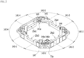
- FIG. 5 is a perspective view of the housing 140 shown in FIG. 1
- FIG. 6 is a perspective view of the magnet 130 disposed at the housing 140.
- the housing 140 may generally have a hollow pillar shape.
- the housing 140 may have a polygonal (e.g. quadrangular or octagonal) or circular opening.
- the housing 140 may include a plurality of edges 141-1 to 141-4 and a plurality of corners 142-1 to 142-4.
- the housing 140 may include first to fourth edges 141-1 to 141-4 spaced apart from each other and first to fourth corners 142-1 to 142-4 spaced apart from each other.
- Each of the corners 142-1 to 142-4 of the housing 140 may be disposed or located between two adjacent edges 141-1 and 141-2, 141-2 and 141-3, 141-3 and 141-4, or 141-4 and 141-1, and may interconnect the edges 141-1 to 141-4.
- the corners 142-1 to 142-4 may be located at the corner portions of the housing 140.
- the number of edges of the housing 140 may be four, and the number of corners thereof may be four. However, the disclosure is not limited thereto. In another embodiment, the number of edges or the corners of the housing may be four or more.
- Each of the edges 141-1 to 141-4 of the housing 140 may be disposed parallel to a corresponding one of the side plates of the cover member 300.
- each of the edges 141-1 to 141-4 of the housing 140 may be larger than the horizontal length of each of the corners 142-1 to 142-4 thereof.
- the disclosure is not limited thereto.
- edges 141-1 to 141-4 of the housing 140 may correspond respectively to the first edges 110b-1 of the bobbin 110, and the corners 142-1 to 142-4 of the housing 140 may correspond respectively to the second edges 110b-2 of the bobbin 110.
- the housing 140 may be provided on the upper portion, the upper end, or the upper surface thereof with a stopper 145 in order to prevent the housing from directly colliding with the inner surface of the upper plate of the cover member 300.
- the stopper 145 may be provided at the upper surface (e.g. a first surface 51a) of each of the corners 142-1 to 142-4 of the housing 140.
- the disclosure is not limited thereto.
- the housing 140 may be provided on the upper portion, the upper end, or the upper surface of each of the corners 142-1 to 142-4 thereof with a guide protrusion 144 for guiding a first frame connection portion 153 of the upper elastic member 150.
- the housing 140 may be provided on the upper portion, the upper end, or the upper surface thereof with at least one first coupling portion 143 coupled to an outer frame 152 of the upper elastic member 150.
- the first coupling portion 143 of the housing 140 may be disposed at at least one of the edges 141-1 to 141-4 or the corners 142-1 to 142-4 of the housing 140.
- the housing 140 may be provided on the lower portion, the lower end, or the lower surface thereof with at least one second coupling portion 149 coupled and fixed to an outer frame 162 of the lower elastic member 160.
- the second coupling portion 149 of the housing 140 may be a protrusion.
- the disclosure is not limited thereto.
- the second coupling portion may be a recess or a plane.
- the first coupling portion 143 of the housing 140 may be coupled into a hole 152a of the first outer frame 152 of the upper elastic member 150 by soldering or thermal fusion
- the second coupling portion 149 of the housing 140 may be coupled into a hole 152a of the second outer frame 162 of the lower elastic member 160 by soldering or thermal fusion.
- the magnet 130 may be disposed or installed at each of the corners 142-1 to 142-4 of the housing 140.
- a settlement portion 141a or a receiving portion for receiving the magnet 130 may be provided in each of the corners 142-1 to 142-4 of the housing 140.
- the settlement portion 141a of the housing 140 may be provided in at least one of the corners 142-1 to 142-4 of the housing 140.
- the settlement portion 141a of the housing 140 may be provided in each of the four corners 142-1 to 142-4.
- the settlement portion 141a of the housing 140 may be a recess having a shape corresponding to the magnet 130, e.g. a concave recess.
- the disclosure is not limited thereto.
- a first opening may be formed in the side surface of the settlement portion 141a of the housing 140 facing the first coil 120, and a second opening may be formed in the lower surface of the settlement portion 141a of the housing 140 facing the second coil 230, for easy mounting of the magnet 130.
- a first surface 11a of the magnet 130 fixed or disposed in the settlement portion 141a of the housing 140 may be exposed through the first opening of the settlement portion 141a.
- the lower surface of the magnet 130 fixed or disposed in the settlement portion 141a of the housing 140 may be exposed through the second opening of the settlement portion 141a.
- the magnet 130 may be fixed in the settlement portion 141a using an adhesive.
- Supporting members 220-1 to 220-4 may be disposed at the corners 142-1 to 142-4 of the housing 140.
- Holes 147 defining paths along which the supporting members 220-1 to 220-4 extend may be provided in the corners 142-1 to 142-4 of the housing 140.
- the housing 140 may include holes 147 formed through the upper portions of the corners 142-1 to 142-4.
- the holes provided in the corners 142-1 to 142-4 of the housing 140 may be depressed the outer surfaces of the corners of the housing 140, and at least a portion of each of the holes may be open toward the outer surface of a corresponding one of the corners.
- the number of holes 147 of the housing 140 may be equal to the number of summer members.
- One end of the supporting member 220 may be connected or bonded to the upper elastic member 150 via a corresponding one of the holes 147.
- the housing 140 may be provided with at least one stopper (not shown) protruding from the outer surfaces of the edges 141-1 to 141-4.
- the at least one stopper may prevent the housing from colliding with the cover member 300 when moved in a direction perpendicular to the optical axis.
- the housing 140 may be further provided with a stopper (not shown) protruding from the lower surface thereof.
- the magnet 130 may be disposed at at least one of the corners 142-1 to 142-4 of the housing 140.
- the magnet 130 may be disposed at each of the corners of the housing 140.
- magnets 130-1 to 130-4 may be disposed at the housing 140 such that at least a portion of each of the magnets overlaps the first coil 120 in a direction perpendicular to the optical axis OA.
- each of the magnets 130-1 to 130-4 may be inserted into or disposed in the settlement portion 141a of a corresponding one of the corners 142-1 to 142-4 of the housing 140.
- the magnets 130-1 to 130-4 may be disposed at the outer surfaces of the corners 142-1 to 142-4 of the housing 140.
- each of the magnets 130-1 to 130-4 may be polyhedral such that the magnets are easily settled in the corners of the housing 140.
- the area of the first surface 11a (see FIG. 13 ) of each of the magnets 130-1 to 130-4 may be larger than the area of a second surface 11b thereof.
- the first surface 11a (see FIG. 13 ) of each of the magnets 130-1 to 130-4 may be a surface facing one surface of the first coil 120 (or the outer surface of the bobbin 110), and the second surface 11b (see FIG. 13 ) may be opposite the first surface 11a.
- the horizontal length of the second surface 11b of each of the magnets 130-1 to 130-4 may be smaller than the horizontal length of the first surface 11a thereof.
- the horizontal direction of the first surface 11a may be a direction of the first surface 11a perpendicular to the direction from the lower surface to the upper surface of each of the magnets 130-1 to 130-4 or a direction of the first surface 11a perpendicular to the optical-axis direction.
- the horizontal direction of the second surface 11b may be a direction of the second surface 11b perpendicular to the direction from the lower surface to the upper surface of each of the magnets 130-1 to 130-4 or a direction of the second surface 11b perpendicular to the optical-axis direction.
- each of the magnets 130-1 to 130-4 may include a portion having a horizontal length L1 (see FIG. 13 ) gradually decreasing from the center of the housing 140 to the corner 142-1, 142-2, 142-3, or 142-4 of the housing 140.
- each of the magnets 130-1 to 130-4 may include a portion having a horizontal length L1 (see FIG. 13 ) decreasing from the first surface 11a to the second surface 11b.
- the horizontal direction may be a direction parallel to the first surface 11a of each of the magnets 130-1 to 130-4.
- Each of the magnets 130-1 to 130-4 may be configured in a single body, and may be disposed such that the first surface 11a facing the first coil 120 has an S pole and the second surface 11b has an N pole.
- the disclosure is not limited thereto.
- the first surface 11a of each of the magnets 130-1 to 130-4 may have an N pole, and the second surface 11b thereof may have an S pole.
- the magnets may be disposed or installed at the corners of the housing 140 such that at least two thereof face each other.
- each of the magnets 130-1 to 130-4 may be disposed at the corners 142-1 to 142-4 of the housing 140.
- the planar shape of each of the magnets 130-1 to 130-4 may be triangular, pentagonal, rhombic, or the like.
- a pair of magnets facing each other may be disposed at only two corners of the housing 140 facing each other.
- FIG. 7A is a plan view of the upper elastic member 150
- FIG. 7B is a plan view of the lower elastic member 160
- FIG. 8 is an assembled perspective view of the upper elastic member 150, the lower elastic member 160, the base 210, the supporting member 220, the second coil 230, and the circuit board 250
- FIG. 9 is a separated perspective view of the second coil 230, the circuit board 250, the base 210, and the OIS position sensor 240.
- the upper elastic member 150 may be coupled to the upper portion, the upper surface, or the upper end of the bobbin 110 or to the upper portion, the upper surface, or the upper end of the housing 140.
- the lower elastic member 160 may be coupled to the upper portion, the upper surface, or the upper end of the bobbin 110 and to the upper portion, the upper surface, or the upper end of the housing 140.
- the upper elastic member 150 and the lower elastic member 160 may elastically support the bobbin 110 relative to the housing 140.
- the supporting member 220 may movably support the housing 140 relative to the base 210 in a direction perpendicular to the optical axis, and the supporting member 220 may connect at least one of the upper or lower elastic member 150 or 160 to the circuit board 250.
- the upper elastic member 150 may include a plurality of upper springs 150-1 and 150-2 separated from each other. In FIG. 7A , two upper springs separated from each other are shown. However, the disclosure is not limited thereto. In another embodiment, the number of upper springs may be three or more.
- the first upper spring 150-1 may be disposed on the first corner 142-1, the first edge 141-1, and the fourth corner 142-4 of the housing 140.
- the second upper spring 150-2 may be disposed on the third corner 142-2, the third edge 141-3, and the second corner 142-2 of the housing 140.
- At least one of the first or second upper spring 150-1 or 150-2 may further include a first inner frame 151 coupled to the bobbin 110, a first outer frame 152 coupled to the housing 140, and a first frame connection portion 153 interconnecting the first inner frame 151 and the first outer frame 152.
- the first inner frame 151 may be referred to as a "first inner portion”
- the first outer frame 152 may be referred to as a "first outer portion.”
- the first inner frame 151 may be provided with a hole 151a, into which the first coupling portion 113 of the bobbin 110 is coupled.
- the disclosure is not limited thereto.
- the first outer frame 152 may be provided with a hole 152a, into which the first coupling portion 143 of the housing 140 is coupled.
- the first outer frame 152 of the first upper spring 150-1 may include a first coupling portion 510a coupled to the first supporting member 220-1, a second coupling portion 520a coupled to the first corner 142-1, and a first connection portion 530a interconnecting the first coupling portion 510a and the second coupling portion 520a.
- the first connection portion 530a may include a first portion 530-1a interconnecting the first coupling portion 510a and a first region of the second coupling portion 520a and a second portion 530-2a interconnecting the first coupling portion 510a and a second region of the second coupling portion 520a.
- first outer frame 152 of the first upper spring 150-1 may include a third coupling portion 510b coupled to the second supporting member 220-2, a fourth coupling portion 520b coupled to the fourth corner 142-4, and a second connection portion 530b interconnecting the third coupling portion 510b and the fourth coupling portion 520b.
- the second connection portion 530b may include a first portion 530-1b interconnecting the third coupling portion 510b and a first region of the fourth coupling portion 520b and a second portion 530-2b interconnecting the third coupling portion 510b and a second region of the fourth coupling portion 520b.
- the second coupling portion 520a and the fourth coupling portion 520b may be connected to each other.
- first supporting member 220-1 may be coupled to the first coupling portion 510a of the first upper spring 150-1
- second supporting member 220-2 may be coupled to the third coupling portion 510b of the first upper spring 150-1, via solder or a conductive adhesive member.
- the first outer frame 152 of the second upper spring 150-2 may include a fifth coupling portion coupled to a third supporting member 220-3, a sixth coupling portion coupled to the third corner 142-3, and a third connection portion interconnecting the fifth coupling portion and the sixth coupling portion.
- the third connection portion may include a first portion interconnecting the fifth coupling portion and a first region of the sixth coupling portion and a second portion interconnecting the fifth coupling portion and a second region of the sixth coupling portion.
- first outer frame 152 of the second upper spring 150-2 may include a seventh coupling portion coupled to a fourth supporting member 220-4, an eighth coupling portion coupled to the second corner 142-2, and a fourth connection portion interconnecting the seventh coupling portion and the eighth coupling portion.
- the fourth connection portion may include a first portion interconnecting the seventh coupling portion and a first region of the eighth coupling portion and a second portion interconnecting the seventh coupling portion and a second region of the eighth coupling portion.
- the sixth coupling portion and the eighth coupling portion may be connected to each other.
- one end of the third supporting member 220-2 may be coupled to the fifth coupling portion of the second upper spring 150-2, and one end of the fourth supporting member 220-4 may be coupled to the seventh coupling portion of the second upper spring 150-2, via solder or a conductive adhesive member.
- the first and third coupling portions 510a and 510b of the first upper spring 150-1 and the fifth and seventh coupling portions of the second upper spring 150-2 may be provided with holes 52, through which the supporting members 220-1 to 220-4 extend.
- each of the supporting members 220-1 to 220-4 extending through the holes 52 may be directly coupled, and may be connected, to a corresponding one of the first, third, fifth, and seventh coupling portions, via a conductive adhesive member or solder 901 (see FIG. 8 ) .
- the first, third, fifth, and seventh coupling portions are regions at which the solder 901 is disposed for coupling with the supporting members 220-1 to 220-4, and may include the holes 52 and regions around the holes 52.
- Each of the first and second portions of the first to fourth connection portions may include a bent portion that is bent at least once or a curved portion that is curved at least once.
- each of the first and second portions may be straight.
- each of the second, fourth, sixth, and eighth coupling portions of the first and second upper springs 150-1 and 150-2 may be disposed on the upper portion, the upper surface, or the upper end of a corresponding one of the corners 142-1 to 142-4 of the housing 140.
- Each of the second, fourth, sixth, and eighth coupling portions of the first and second upper springs 150-1 and 150-2 may contact the upper surface of a corresponding one of the corners 142-1 to 142-4 of the housing 140, and may be supported by a corresponding one of the corners 142-1 to 142-4 of the housing 140.
- first to fourth connection portions of the first and second upper springs 150-1 and 150-2 are not supported by the upper surface of the housing 140, and may be spaced apart from the housing 140.
- a damper (not shown) may be disposed in an empty space between the first to fourth connection portions of the first and second upper springs and the housing 140 in order to prevent oscillation due to vibration.
- upper spring may be referred to as an "upper elastic unit” or an elastic unit
- lower spring may be referred to as a “lower elastic unit” or an elastic unit
- the lower elastic member 160 may include a single lower spring. However, the disclosure is not limited thereto. In another embodiment, the lower elastic member may include two or more lower springs.
- the lower elastic member 160 may include a second inner frame 161 coupled or fixed to the lower portion, the lower surface, or the lower end of the bobbin 110, second outer frames 162-1 to 162-3 coupled or fixed to the lower portion, the lower surface, or the lower end of the housing 140, and a second frame connection portion interconnecting the second inner frame 161 and the second outer frames 162-1 to 162-3.
- the second inner frame 161 may be provided with a hole 161a, into which the second coupling portion 117 of the bobbin 110 is coupled, and each of the second outer frames 162-1 to 162-3 may be provided with a hole 162a, into which the second coupling portion 149 of the housing 140 is coupled.
- the lower elastic member may include four second outer frames coupled to the bobbin 110, four second outer frames coupled to the housing 140, and four second frame connection portions.
- the disclosure is not limited thereto.
- the lower elastic member 160 may include connection frames 164-1 interconnecting four second outer frames 162.
- the lower elastic member 1600 may include four connection frames 164-1.
- the disclosure is not limited thereto.
- connection frames 164-1 may be located outside OIS coils 230-1 to 230-4 (see FIG. 9 ) and the magnets 130-1 to 130-4 based on the OIS coils 230-1 to 230-4 and the magnets 130-1 to 130-4 in order to avoid spatial interference with the OIS coils 230-1 to 230-4 and the magnets 130-1 to 130-4.
- the outside of the OIS coils 230-1 to 230-4 and the magnets 130-1 to 130-4 may be opposite a region in which the center of the bobbin 110 or the center of the housing 140 is located based on the OIS coils 230-1 to 230-4 and the magnets 130-1 to 130-4.
- connection frames 164-1 may be located so as not to overlap the second coils 230-1 to 230-4 and/or the magnets 130-1 to 130-4 in the optical-axis direction.
- the disclosure is not limited thereto.
- at least portions of the connection frames 164-1 may be aligned with or overlap the OIS coils 230-1 to 230-4 and/or the magnets 130-1 to 130-4 in the optical-axis direction.
- Each of the upper springs 150-1 and 150-2 and the lower spring 160 may be realized as a leaf spring; however, the disclosure is not limited thereto.
- Each of the upper springs and the lower spring may be realized as a coil spring or the like.
- the supporting members 220-1 to 220-4 may be disposed so as to correspond to the corners 142-1 to 142-4 of the housing 140, and may interconnect the first and second upper springs 150-1 and 150-2 and the circuit board 250.
- the first and second supporting members 220-1 and 220-2 connected to the first upper spring 150-1 and the third and fourth supporting members 220-3 and 220-4 connected to the second upper spring 150-2 may be independently connected to the circuit board 250.
- the first to fourth supporting members 220-1 to 220-4 may be spaced apart from the housing 140, not fixed to the housing 140, and one end of each of the first to fourth supporting members 220-1 to 220-4 may be directly connected or coupled to a corresponding one of the first coupling portion 510a, the third coupling portion 510b, the fifth coupling portion, and the seventh coupling portion of the upper elastic member 150.
- each of the first to fourth supporting members 220-1 to 220-4 may be directly connected or coupled to the circuit board 250.
- each of the first to fourth supporting members 220-1 to 220-4 may extend through a hole 147 formed in a corresponding one of the corners 142-1 to 142-4 of the housing 140.
- the disclosure is not limited thereto.
- the supporting members may be disposed adjacent to boundary lines between the first edges 141-1 to 141-4 and the corners 142 of the housing 140, and may not extend through the corners 142-1 to 142-4 of the housing 140.
- the first coil 120 may be directly connected or coupled to a corresponding one of the first inner frames of the first and second upper springs 150-1 and 150-2.
- one end of the first coil 120 may be connected to a first bonding portion 19a provided at one end of the first inner frame of the first upper spring 150-1, and the other end of the first coil 120 may be connected to a second bonding portion 19b provided at one end of the first inner frame of the second upper spring 150-2.
- a driving signal may be provided from the circuit board 250 to the first coil 120 through the first and second upper springs 150-1, one of the first and second supporting members 220-1 and 220-2, and one of the third and fourth supporting members 220-3 and 220-4.
- the supporting member 220 may be realized as an elastic supporting member, such as a suspension wire, a leaf spring, or a coil spring.
- the supporting member 220 may be integrally formed with the upper elastic member 150.
- the base 210 may have an opening corresponding to the opening of the bobbin 110 and/or the opening of the housing 140, and may be configured in a shape coinciding with or corresponding to the shape of the cover member 300, such as a quadrangular shape.
- the base 210 may be provided with a stair 211, to which an adhesive may be coated when fixing the cover member 300 by adhesion.
- the stair 211 may guide the side plate of the cover member 300 coupled to the upper side thereof, and the lower end of the side plate of the cover member 300 may contact the stair 211.
- the stair 211 of the base 210 may be fixed to the lower end of the side plate of the cover member 300 by adhesion using an adhesive.
- a support portion 255 or a supporting portion may be provided at a region of the base 210 facing a terminal 251 of the circuit board 250.
- the support portion 255 may support a terminal surface 253 of the circuit board 250 at which the terminal 251 is formed.
- the base 210 may be provided in each corner thereof with a concave recess 212 in order to avoid spatial interference with the other end of a corresponding one of the supporting members 220-1 to 220-4 coupled to the circuit board 250.
- the base 210 may be provided in the upper surface thereof with settlement recesses 215-1 and 215-2, in which first and second OIS position sensors 240a and 240b are disposed.
- a settlement portion (not shown), in which a filter 610 of a camera module 200 is installed, may be formed in the lower surface of the base 210.
- the base 210 may be provided in the upper surface thereof with protrusions 21, which are coupled into a recess 23a provided in a side surface of the circuit board 250 and a recess 23b provided in a side surface of a circuit member 231.
- the base 210 may be provided on the upper surface thereof around the opening thereof with protrusions 19, which are coupled into the opening of the circuit board 250 and an opening of the circuit member 231.
- the second coil 230 may be disposed at the upper portion of the circuit board 250, and the OIS position sensor 240 may be disposed in the settlement recesses 215-1 and 215-2 of the base 210 located under the circuit board 250.
- the OIS position sensor 240 may include first and second OIS position sensors 240a and 240b, and the first and second OIS position sensors 240a and 240b may sense displacement of an OIS operation unit in a direction perpendicular to the optical axis.
- the OIS operation unit may include the AF operation unit and components mounted at the housing 140.
- the OIS operation unit may include the AF operation unit and the housing 140.
- the magnets 130-1 to 130-4 may be further included.
- the AF operation unit may include the bobbin 110 and components mounted at the bobbin 110 so as to be movable with the bobbin 110.
- the AF operation unit may include the bobbin 110 and the lens (not shown) and the first coil 120 mounted at the bobbin 110.
- the circuit board 250 is disposed on the upper surface of the base 210, and may have an opening corresponding to the opening of the bobbin 110, the opening of the housing 140, and/or the opening of the base 210.
- the circuit board 250 may be configured in a shape coinciding with or corresponding to the shape of the upper surface of the base 210, such as a quadrangular shape.
- the circuit board 250 may be provided with at least one terminal surface 253 at which a plurality of terminals 251 or pins for receiving electrical signals from outside is provided.
- the second coil 230 may be disposed under the bobbin 110 and/or the housing 140.
- the second coil 230 is disposed at the upper portion of the circuit board 250 so as to correspond to the magnets 130-1 to 130-4 disposed at the housing 140.
- the second coil 230 may be disposed so as to correspond to or overlap the magnets 130-1 to 130-4 disposed at the corners 142-1 to 142-4 of the housing 140 in the optical-axis direction.
- the second coil 230 may include four OIS coils 230-1 to 230-4 disposed or formed at four corners of the quadrangular circuit member 231.
- the OIS coils 230-1 to 230-4 may be referred to as "coil units.”
- the second coil 230 may include two OIS coils 230-1 and 230-3 for a second direction and two OIS coils 230-2 and 230-4 for a third direction.
- the disclosure is not limited thereto.
- the second coil 230 may include a single OIS coil for the second direction and a single OIS coil for the third direction, and may include four or more OIS coils.
- Each of the OIS coils 230-1 to 230-4 may be connected to the circuit board 250, for example, to a corresponding one of the terminals of the circuit board 250.
- the circuit board 250 may include bonding portions or pads S1 to S4 (see FIG. 9 ) connected to the OIS coils 230-1 to 230-4.
- the housing 140 may be moved in a direction perpendicular to the optical axis, for example, in the x-axis direction and/or the y-axis direction, due to interaction between the magnets 130-1 to 130-4 and the OIS coils 230-1 to 230-4, whereby handshake compensation may be performed.
- the OIS coils 230-1 to 230-4 may be provided at the circuit member 231, rather than the circuit board 250.
- each of the OIS coils 230-1 to 230-4 may be configured in the form of a ring-shaped coil block or an FP coil.
- each of the OIS coils may be configured in the form of a circuit pattern formed on the circuit board 250.
- the circuit member 231 may be referred to as a "board” or a "coil board.”
- circuit board 250 and the circuit member 231 are separate components, which are referred to individually. However, the disclosure is not limited thereto.
- the circuit board 250 and the circuit member 231 may be commonly referred to as a "circuit member” or a "board.” In this case, the other end of each of the supporting members may be coupled to the "circuit member” (e.g. the lower surface of the circuit member).
- recesses 24 may be provided in the corners of the circuit member 231, and the supporting members 220-1 to 220-4 may extend through the recesses 24 of the circuit member 231.
- the circuit member may be provided with holes formed through the circuit member instead of the recesses.
- Each of the first and second OIS position sensors 240a and 240b may be a Hall sensor. Any sensor may be used as long as the sensor is capable of sensing the intensity of a magnetic field.
- each of the first and second OIS position sensors 240a and 240b may be configured in the form of a driver including a Hall sensor, or may be realized as a position sensor, such as a Hall sensor, alone.
- Each of the first and second OIS position sensors 240a and 240b may be connected to the circuit board 250, and may receive a driving signal through the circuit board 250. In addition, output signals of the first and second OIS position sensors 240a and 240b may be transmitted to the circuit board 250.
- Terminals 251 may be provided at the terminal surface 253 of the circuit board 250.
- a driving signal may be provided to the first coil 120 through a plurality of terminals 251 provided at the terminal surface 253 of the circuit board 250.
- the circuit board 250 may be an FPCB.
- the terminals of the circuit board 250 may be directly formed on the surface of the base 210 using a surface electrode scheme or the like.
- the circuit board 250 may include holes 250a through which the supporting members 220-1 to 220-4 extend.
- the position and number of holes 250a may correspond to or coincide with the position and number of supporting members 220-1 to 220-4.
- the circuit board 250 may be provided in the corners thereof with escape recesses instead of the holes 250a.
- One end of each of the supporting members 220-1 to 220-4 may be coupled to the first outer frame of the upper elastic member 140 via solder, and the other end of each of the supporting members 220-1 to 220-4 may be coupled to the lower surface of the circuit board 250.
- the supporting members 220-1 to 220-4 may extend through the holes 250a of the circuit board 250 and may be connected to circuit patterns disposed on the lower surface of the circuit board 250 via solder.
- the disclosure is not limited thereto.
- the circuit board 250 may have no holes, and the supporting members 220-1 to 220-4 may be connected to circuit patterns or pads formed on the upper surface of the circuit board 250.
- the supporting members 220-1 to 220-4 may be connected to the circuit member 231, and the circuit member 231 may connect the supporting members 220-1 to 220-4 to the circuit board.
- the cover member 300 may receive the bobbin 110, the first coil 120, the magnet 130, the housing 140, the upper elastic member 150, the lower elastic member 160, the supporting member 220, the second coil 230, the OIS position sensor 240, and the circuit board 250 in a receiving space formed together with the base 210.
- the cover member 300 may be formed in the shape of a box, the lower portion of which is open and which includes an upper plate and side plates.
- the lower portion of the cover member 300 may be coupled to the upper portion of the base 210.
- the shape of the upper plate of the cover member 300 may be polygonal, for example, quadrangular or octagonal.
- the cover member 300 may be provided in the upper plate thereof with an opening, through which the lens (not shown) coupled to the bobbin 110 is exposed to external light.
- the cover member 300 may be made of a nonmagnetic material, such as SUS in order to prevent a phenomenon in which the magnet 130 attracts the cover member.
- the cover member may be made of a magnetic material so as to perform the function of a yoke that increases electromagnetic force between the first coil 120 and the magnet 130.
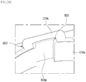
- FIG. 10A is a first perspective view of the first corner 142-1 of the housing 140
- FIG. 10B is an EF sectional view of the first corner of the housing of FIG. 10A
- FIG. 11 is a second perspective view of the first corner 142-1 of the housing 140 shown in FIG. 10 .
- the description of the first corner 142-1 may be equally applied to the other corners 142-2 to 142-4.
- each of the corners 142-1 to 142-4 of the housing 140 may have an upper surface including at least one stair surface in the optical-axis direction.
- the housing 140 includes a first surface 51a, to which the upper elastic member 150 (e.g. the first outer frame 152) is coupled, a second surface 31a disposed higher than the bottom surface 51b of the housing 140 and lower than the first surface 51a thereof, and an inclined surface 31b adjacent to the second surface 31a (or the hole 147) and having a predetermined angle ⁇ 1 relative to the second surface 31a.
- the upper elastic member 150 e.g. the first outer frame 152
- second surface 31a disposed higher than the bottom surface 51b of the housing 140 and lower than the first surface 51a thereof
- the upper surface 51 of each of the corners 142-1 to 142-3 may include a first surface 51a, to which the upper elastic member 150 (e.g. the first outer frame 152) is coupled, a second surface 31a having a first stair relative to the first surface 51a in the optical-axis direction, and an inclined surface 31b having a predetermined angle relative to the first surface 51a or the second surface 31b.
- the upper elastic member 150 e.g. the first outer frame 152
- the second surface 31a having a first stair relative to the first surface 51a in the optical-axis direction
- an inclined surface 31b having a predetermined angle relative to the first surface 51a or the second surface 31b.
- the inclined surface 31b may be formed at each corner of the housing 140.
- the inclined surface 31b may abut the second surface 31a, and may extend from the second surface 31a.
- the housing 140 may further include a third surface 51c having a second stair relative to the first surface 51a in the optical-axis direction.
- the first stair and the second stair may be identical to each other.
- the disclosure is not limited thereto.
- the first stair and the second stair may be different from each other.
- the second surface 31a may be a horizontal surface parallel to the first surface 51a
- the third surface 51c may be parallel to the first surface 51a.
- the disclosure is not limited thereto. In another embodiment, both may not be parallel to each other.
- the inclined surface 31b may be spaced apart from the first surface 51a, and may be inclined downwards from the second surface 31a, which is a horizontal surface.
- the second surface 31a may be located outside the first surface 51a, and the third surface 51c may be located inside the first surface 51a.
- the width of the inclined surface 31b may gradually decrease from a boundary line between the second surface 31a and the inclined surface 31b to the tip end of the inclined surface 31b. This serves to avoid spatial interference with the cover member 300.
- the width of the inclined surface 31b (or the maximum value of the width of the inclined surface 31b) may be smaller than or equal to the width of the second surface 31a (or the minimum value of the width of the second surface 31a).
- the ratio W2:W1 of the width W2 of the distal end of the inclined surface 31b to the first width W1 of the inclined surface 31b abutting the second surface 31a may be 1:2 to 1:5.
- the ratio W2:W1 may be 1:3 to 1:4.
- the length L2 of the inclined surface 31b may be smaller than or equal to the length L1 of the second surface 31a (L2 ⁇ L1). This serves to secure a space necessary to form the hole 147 in the second surface 31a and to inhibit spatial interference between the inclined surface 31b and the cover member 300.
- the ratio L2:L1 of the length L2 of the inclined surface 31b to the length L1 of the second surface 31a may be 1:1.03 to 1:1.5.
- the value L1/L2 is less than 1.03, it is not possible to secure a sufficient space to form the hole 147 in the second surface 31a.
- spatial interference may occur between the cover member 300 and the housing 140.
- the length L2 of the inclined surface 31b may be larger than the length L1 of the second surface 31a.
- the first surface 51a of each of the corners 142-1 to 142-4 may be located higher than the second surface 31a and the third surface 51c. This serves to prevent an adhesive or a damper from flowing to the third surface 51c when the adhesive is injected into adhesive injection recesses 146a and 146b or when the damper is coated on the second surface 31a.
- the guide protrusion 144 of the housing 140 may be disposed at the third surface 51c of each of the corners 142-1 to 142-4.
- the disclosure is not limited thereto.
- the first coupling portion 143 of the housing 140 may be disposed at the first surface 51a of each of the corners 142-1 to 142-4 of the housing 140, and may be a protrusion.
- the disclosure is not limited thereto.
- the first coupling portion may be a recess or a plane.
- At least one adhesive injection recess 146a and 146b may be provided in each of the corners 142-1 to 142-4 of the housing 140.
- the at least one adhesive injection recess 146a and 146b may be depressed the upper surface 51 of each of the corners 142-1 to 142-4.
- the at least one adhesive injection recess 146a and 146b may be disposed in the second surface 31a of each of the corners 142-1 to 142-4 of the housing 140.
- the at least one adhesive injection recess 145a and 146b may abut the first surface 51a of each of the corners 142-1 to 142-4 of the housing 140.
- both may be spaced apart from each other.
- the at least one adhesive injection recess 146a and 146b may include through holes 46a and 46b formed through each of the corners 142-1 to 142-4.
- the through holes 46a and 46b may expose at least a portion of the magnet 130 (e.g. at least a portion of the upper surface of the magnet 130).
- the adhesive may be sufficiently coated on the magnet 130, whereby force of fixing between the magnet 130 and the housing 140 may be increased.
- each of the adhesive injection recesses 146a and 146b may be 0.3 mm to 0.8 mm.
- the diameter of each of the adhesive injection recesses 146a and 146b may be 0.4 mm to 0.6 mm.
- each of the adhesive injection recesses 146a and 146b is less than 0.3 mm, the size thereof is too small, whereby the adhesive may not be smoothly injected thereinto.
- the diameter of each of the adhesive injection recesses 146a and 146b exceeds 0.8 mm, the size thereof is too large, whereby it is not possible to secure a sufficient space to form the hole 147 of the housing 140.
- the through holes 46a and 46b may be provided in a portion of the bottom and a portion of the side surface of the at least one adhesive injection recess 145a and 146b.
- the adhesive injected into the adhesive injection recesses 145a and 146b is slowly supplied to the settlement portion 141a through the through holes 46a and 46b, whereby the adhesive is uniformly coated on the settlement portion 141a.
- Two adhesive injection recesses 146a and 146b which are spaced apart from each other, may be disposed in each of the corners 142-1 to 142-4 of the housing 140, and a stair, a projection, or a protrusion 47 protruding from the second surface 31a in the optical-axis direction may be disposed between the two adhesive injection recesses 146a and 146b.
- the protrusion 47 may serve to uniformly inject the adhesive into the two adhesive injection recesses 146a and 146b.
- the upper surface of the protrusion 47 may form a stair with the first surface 51a in the optical-axis direction, and may be disposed lower than the first surface 51a and higher than the second surface 31a. However, the disclosure is not limited thereto. In another embodiment, the upper surface of the protrusion 47 may be the same level as the first surface 51a.
- the protrusion 47 may be located between a side surface 33a and the hole 147, and may be spaced apart from the hole 147. However, the disclosure is not limited thereto. In another embodiment, both may abut each other.
- the diameter of the hole 147 of the housing may gradually increase in the direction from the lower surface to the upper surface of the housing 140 for easy application of the damper.
- the disclosure is not limited thereto.
- the diameter of the hole 147 of the housing may be uniform.
- the diameter of the uppermost end of the hole 147 of the housing 140 may be 0.4 mm to 0.6 mm, and the diameter of the lowermost end of the hole 147 of the housing 140 may be 0.3 mm to 0.4 mm.
- the hole 147 of the housing 140 may be disposed so as to be located outside the adhesive injection recesses 146a and 146b.
- the hole 147 of the housing 140 may be formed in at least one of the second surface 31a or the inclined surface 31b.
- the hole 147 of the housing 140 may be formed over the second surface 31a and the inclined surface 31b of the housing 140.
- a portion of the hole 147 of the housing 140 may be formed in the second surface 31a, and the remaining portion thereof may be formed in the inclined surface 31b.
- the hole 147 of the housing 140 may be located between the corner of the upper surface 51 of each of the corners 142-1 to 142-4 and the stopper 145.
- the corners 142-1 to 142-4 of the housing 140 may correspond to corners of the cover member 300.
- the housing 140 may include a body and a protrusion 71a protruding from a side surface of the body.
- the body of the housing 140 may include edges 141-1 to 141-4 and corners 142-1 to 142-4.
- the protrusion 71a may be disposed at each corner or corner portion of the housing 140, and may include an inclined surface 31b formed on the upper surface of the protrusion 71a and a hole 147, at least a portion of which is disposed in the inclined surface 31b.
- the supporting member 220 may be disposed at each corner of the housing 140.
- the protrusion 71a may protrude from a side surface 148 (or the outer surface) of each of the corners 142-1 to 142-4 in a diagonal direction.
- the diagonal direction may be a direction from the center of the housing 140 to each corner of the housing 140.
- the diagonal direction may be a direction from the center of the housing 140 to a corresponding one of the corners 142-1 to 142-4 of the housing 140.
- the hole 147 of the housing 140 may be formed through the protrusion 71a.
- the protrusion 71a of the housing 140 may be chamfered.
- the inclined surface 31b of the housing 140 may be formed at the upper surface of the protrusion 71a.
- the housing 140 may include an upper plate and a side plate extending downwards from the upper plate.
- the supporting member 220 may be disposed at each corner of the upper plate of the housing 140, and may be coupled to the upper elastic member 150.
- the upper plate of the housing 140 may include a hole 147 which is formed in each corner of the upper plate and through which the supporting member 220 extends.
- a portion of the upper plate of the housing 140 may include a protrusion 71a protruding from the side plate of the housing 140.
- the protrusion 71a may be formed at each corner of the upper plate of the housing 140.
- the protrusion 71a may include an inclined surface 31b formed at the upper surface of the protrusion 71a.
- the thickness of the protrusion 71a of the housing 140 (the length thereof in the optical-axis direction) is decreased in order to realize a lens moving apparatus having a small height, whereby strength of the protrusion 71a may be reduced.
- the thickness of the protrusion 71a according to the embodiment(the length thereof in the optical-axis direction) may be decreased in the direction from the center of the housing 140 to each of the corners 142-1 to 142-4 of the housing 140. That is, the upper surface of the protrusion 71a may have both a second surface 31a and an inclined surface 31b.
- the embodiment is capable of securing rigidity of the protrusion 71a of the housing 140 and realizing a lens moving apparatus having a small height.
- a lower surface 72 of the protrusion 71a and the outer surface 148 of each of the corners 142-1 to 142-4 may be a concave recess.
- an escape recess 148a may be provided in the outer surface 148 of each of the corners 142-1 to 142-4.
- the escape recess 148a may be connected to the hole 147 of the housing 140, and may be hemispherical or semi-oval. However, the disclosure is not limited thereto.
- the lower portion or the lower end of the escape recess 148a may be connected to the lower surface of the housing 140.
- the diameter of the escape recess 148a may gradually decrease in the direction from the upper portion to the lower portion thereof.
- the disclosure is not limited thereto.
- FIG. 12 is a perspective view of the settlement portion when viewed from the lower side of the housing 140, and FIG. 13 shows the magnet 130-1 disposed in the settlement portion 141a of FIG. 12 .
- the settlement portion 141a may include an upper surface 41a and a side surface 41b.
- At least one guide recess P1 to P5 may be provided in at least one of the upper surface 41a or the side surface 41b of the settlement portion 141a.
- the at least one guide recess P1 to P5 may guide flow of an adhesive injected through the adhesive injection recesses 146a and 146b such that the adhesive is uniformly coated on the settlement portion 141a.
- the diameter of the adhesive injection recesses 146a and 146b may decrease.
- the guide recesses P1 to P5 may enable the adhesive to sufficiently flow into the settlement portion 141a of the housing 140 through the adhesive injection recesses 146a and 146b having the small diameter.
- At least one first guide recess P1 to P4 may be provided in a side surface 41b1 of the settlement portion 141a abutting or adjacent to the adhesive injection recesses 146a and 146b.
- a plurality of first guide recesses P1 to P4 may be provided.
- the first guide recesses P1 to P4 may be connected to the adhesive injection recesses 146a and 146b in order to guide the adhesive.
- the first guide recesses P1 to P4 may be connected to the through holes 46a and 46b of the adhesive injection recesses 146a and 146b.
- At least one second guide recess P5 may be provided in the upper surface 41a of the settlement portion 141a.
- the second guide recess P5 may be connected to the through holes 46a and 46b of the adhesive injection recesses 146a and 146b.
- An adhesive 80 injected through the adhesive injection recesses 146a and 146b in order to fix the magnet 130 in the settlement portion 141a of the housing 140 may be disposed in the guide recesses P1 to P5.
- a catching protrusion 18 protruding toward the center of a first opening of the settlement portion 141a may be provided on one end and/or the other end of the first opening of the settlement portion 141a.
- the catching protrusion 18 may serve to prevent each of the magnets 130-1 to 130-4 from being separated from the settlement portion 141a due to external force or external impact.
- FIG. 14 shows the first upper spring 150-1 and the first supporting member 220-1 disposed at the first corner 142-1
- FIG. 15A is a side perspective view of the first corner 142-1 of FIG. 14
- FIG. 15B shows a damper 45 disposed between the first outer frame 152 and the first corner 142-1 of the housing 140 shown in FIGs. 14 and 15A
- FIG. 17 is a sectional view of the lens moving apparatus 100 shown in FIG. 3 when viewed in an AB direction
- FIG. 18 is a sectional view of the lens moving apparatus 100 shown in FIG. 3 when viewed in a CD direction.
- first corner 142-1 of FIGs. 14 , 15A and 15B may be equally applied to the second to fourth corners 142-2 to 142-4, and the description of the first supporting member 220-1 of FIGs. 14 , 15A and 15B may be equally applied to the second to fourth supporting members 220-2 to 220-4.
- the first corner 142-1 of the housing 140 may include a first surface 51a, a second surface 31a, and an inclined surface 31b.
- the first corner 142-1 of the housing 140 may further include a third surface 51c.
- the second surface 31a may be a plane perpendicular to the optical axis, and the second surface 31a and the inclined surface 31b may be connected to each other or may abut each other.
- At least one of the first to fourth corners 142-1 to 142-4 may include a first surface 51a, a second surface 31a, and an inclined surface 31b.
- a center line 10-1 of the hole 147 of the housing 140 may be located closer to the first surface 51a based on a boundary line between the second surface 31a and the inclined surface 31b.
- the disclosure is not limited thereto.
- the distance from a center line 190-1 of the hole 147 to the boundary line between the second surface 31a and the inclined surface 31b may be a predetermined value or less.
- the predetermined value may be 0.1 mm to 0.3 mm.
- the disclosure is not limited thereto.
- the center of the hole 147 of the housing 140 may overlap or may be aligned with the boundary line between the second surface 31a and the inclined surface 31b.
- the hole 147 of the housing 140 may not overlap the magnet 130 in the optical-axis direction.
- An angle ⁇ at which the inclined surface 31b is inclined downwards from the second surface 31a may be 10 degrees to 30 degrees.
- the angle ⁇ may be 12 degrees to 25 degrees.
- the angle ⁇ may be 12.8 degrees.
- the angle ⁇ may be a value obtained by subtracting the angle ⁇ 1 of FIG. 10B from 180 degrees.
- spatial interference may occur between the upper springs 150-1 and 150-2 and the corners 142-1 to 142-4 of the housing 140 and/or spatial interference may occur between the supporting members 220-1 to 220-4 and the corners 142-1 to 142-4 of the housing 140, whereby the lens moving apparatus may malfunction or may be damaged.
- the thickness of the protrusion 71a may be decreased, whereby strength of the protrusion 71a may be reduced.
- the thickness of the lower end of the protrusion 71a (the length thereof in the optical-axis direction) may be increased so as to be larger than the thickness of the upper end of the protrusion 71a (the length thereof in the optical-axis direction) in order to increase the strength of the protrusion 71a.
- the thickness of the damper 45 located between each of the upper springs 150-1 and 150-2 and the inclined surface may be increased, whereby shock-absorbing force of the damper may vary and thus AF operation and/or OIS operation may be abnormally performed.
- the second surface 31a and the inclined surface 31b may have a stair formed from the upper surface 51a of the first corner 142-1 in the optical-axis direction.
- the housing 140 may further include a side surface connected between the first surface 51a and the second surface 31a, e.g. a stair surface.
- the upper elastic member 150 (e.g. the first outer frame 152) may be spaced apart from the second surface 31a and the inclined surface 31b of the first corner 142-1.
- a first distance H1 from the lower surface of the first outer frame 152 of each of the upper springs 150-1 and 150-2 to the second surface 31a of each of the corners 142-1 to 142-4 in the optical-axis direction may be smaller than a second distance H2 from the lower surface of the first outer frame 152 of each of the upper springs 150-1 and 150-2 to the inclined surface 31a of each of the corners 142-1 to 142-4 in the optical-axis direction (H1 ⁇ H2).
- the first distance H1 may be 0.01 mm to 0.02 mm.
- the first distance H1 may be 0.15 mm.
- the second distance H2 may be 0.25 mm to 0.3 mm.
- the second distance H2 may be 0.27 mm.
- the embodiment is capable of preventing spatial interference between the upper springs 150-1 and 150-2 and the corners 142-1 to 142-4 of the housing 140 and/or spatial interference between the supporting members 220-1 to 220-4 and the corners 142-1 to 142-4 of the housing 140 due to the inclined surface 31b provided at each of corners 142-1 to 142-4.
- the damper 45 may be disposed on the second surface 31a and the inclined surface 31b of the housing 140 (e.g. each of the corners 142-1 to 142-4).
- the damper 45 may be disposed between the lower surface of the first outer frame 152 of each of the upper springs 150-1 and 150-2 and the second surface 31a of each of corners 142-1 to 142-4 and between the lower surface of the first outer frame 152 and the inclined surface 31b of each of corners 142-1 to 142-4.
- the damper 45 may serve to absorb or alleviate vibration of each of the upper elastic members 150-1 and 150-2.
- a portion of the damper 45 may be disposed on a portion of the upper surface of the first outer frame 152 of each of the upper elastic members 150-1 and 150-2.
- a portion of the damper 45 may be disposed in the hole 147 of the housing 140, whereby vibration of each of the supporting members 220-1 to 220-4 may be absorbed or alleviated.
- the thickness of the damper 45 (the length thereof in the optical-axis direction) may increase in the direction from the second surface 31a to the inclined surface 31b.
- a portion of the damper 45 may be disposed in the adhesive injection recesses 146a and 146b of the housing 140.
- the damper 45 may be injected between the first outer frame 152 of each of the upper springs 150-1 and 150-2 and the horizontal surface of each of the corners 142-1 to 142-4 and between the first outer frame 152 and the inclined surface 31b.
- the damper 45 When the damper 45 is coated on the adhesive injection recesses 146a and 146b, the second surface 31a, and the inclined surface 31b, the damper 45 may be uniformly coated on the opposite side of the adhesive injection recesses 146a and 146b along the inclined surface 31b.
- a portion of the damper 45 may be disposed on the adhesive injection recesses 146a and 146b.
- the damper 45 may fill the through holes 46a and 46b of the adhesive injection recesses 146a and 146b in order to cover the same, whereby it is possible to reduce or minimize the amount of foreign matter discharged from the adhesive (e.g. bonding resin).
- the adhesive e.g. bonding resin
- FIG. 16A shows a first upper spring 150-1 and a first supporting member 220-1 disposed at a housing 140-1 according to another embodiment.
- the housing 140-1 may include a first surface 51a, to which an upper elastic member 150 (e.g. a first outer frame 152) is coupled, and an inclined surface 31b1 disposed higher than a bottom surface 51b of the housing 140 and lower than the first surface 51a thereof.
- an upper elastic member 150 e.g. a first outer frame 152
- an inclined surface 31b1 disposed higher than a bottom surface 51b of the housing 140 and lower than the first surface 51a thereof.
- the housing 140-1 may include a protrusion 71a1 including a first surface 51a and an inclined surface 31b1.
- the protrusion 71a1 may further include a first side surface 33a.
- a first hole 147 may be formed in the inclined surface 31b1.
- the inclined surface 31b1 may be inclined downwards from the first surface 51a of the housing 140-1 at a predetermined angle.
- the inclined surface 31b1 may be spaced apart from the first surface 51a, and may have a stair formed from the first surface 51a in the optical-axis direction.
- a damper may be disposed between the inclined surface 31b1 and the lower surface of the upper elastic member 150.
- the housing 140-1 may further include a first side surface 33a connected between the first surface 51a and the inclined surface 31b1 and a second side surface 33b connected to the inclined surface 31b1, and the inclined surface 31b1 may be disposed between the first side surface 33a and the second side surface 33b.
- FIG. 16B shows a first upper spring 150-1 and a first supporting member 220-1 disposed at a housing 140-2 according to another embodiment.
- the housing 140-2 may include a first surface 51a, to which an upper elastic member 150 (e.g. a first outer frame 152) is coupled, and an inclined surface 31b2 extending from the first surface 51a and inclined downwards from the first surface 51a at a predetermined angle ⁇ .
- an upper elastic member 150 e.g. a first outer frame 152
- an inclined surface 31b2 extending from the first surface 51a and inclined downwards from the first surface 51a at a predetermined angle ⁇ .
- the housing 140-2 may include a protrusion 71a2 including a first surface 51a and an inclined surface 31b2.
- the inclined surface 31b2 may abut the first surface 51a, and a damper may be disposed between the inclined surface 31b2 and the lower surface of the upper elastic member 150.
- a first hole 147 may be formed in the inclined surface 31b2.
- the inclined surface 31b2 may be inclined downwards from the first surface 51a of the housing 140-1 at the predetermined angle ⁇ .
- FIG. 16C shows a first upper spring 150-1 and a first supporting member 220-1 disposed at a housing 140-3 according to a further embodiment.
- the housing 140-3 may include a first surface 51a, to which an upper elastic member 150 (e.g. a first outer frame 152) is coupled, a second surface 31a disposed higher than a bottom surface 51b of the housing 140 and lower than the first surface 51a thereof, and an inclined surface 31b3 spaced apart from the second surface 31a and inclined by a predetermined angle.
- an upper elastic member 150 e.g. a first outer frame 152
- a second surface 31a disposed higher than a bottom surface 51b of the housing 140 and lower than the first surface 51a thereof
- an inclined surface 31b3 spaced apart from the second surface 31a and inclined by a predetermined angle.
- the housing 140-3 may include a protrusion 71a2 including a first surface 51a, a second surface 31a, and an inclined surface 31b3.
- the protrusion 71a2 may further include first to third side surfaces 33a to 33c, a description of which will follow.
- the inclined surface 31b3 may be inclined downwards from the first surface 51a or the second surface 31a by the predetermined angle.
- the inclined surface 31b3 may have a stair H3 formed from the second surface 31a in the optical-axis direction.
- the description of the angle ⁇ of FIGs. 16A and 16B may be equally applied to the angle of the inclined surface 31b3.
- a first hole 147 may be formed in at least one of the second surface 31a or the inclined surface 31b3.
- the housing 140-3 may further include a first side surface 33a connected between the first surface 51a and the second surface 31a, the second surface 31a, a second side surface 33b connected to the inclined surface 31b1, and a third side surface 33c connected between the second surface 31a and the inclined surface 31b3, and the inclined surface 31b3 may be disposed between the second side surface 33b and the third side surface 33c.
- each of the first side surface 33a and the third side surface 33c may be a stair surface in the optical-axis direction.
- each of the housings 140-1 to 140-3 may further include a third surface 51c of FIG. 10A .
- the description of the first corner 142-1 of each of the housings 140-1 to 140-3 of FIGs. 16A to 16C may be equally applied to the second to fourth corners 142-2 to 142-4 of each of the housings 140-1 to 140-3, and the description of the first supporting member 220-1 of FIGs. 16A to 16C may be equally applied to the second to fourth supporting members 220-2 to 220-4.
- the lens moving apparatus 100 may further include a sensing magnet for feedback AF driving, an AF position sensor, a circuit board connected to the AF position sensor, and a balancing magnet.
- FIG. 19 shows magnets 130-1 to 130-4, a sensing magnet 180, an AF position sensor 170, a circuit board 190, and a balancing magnet 185 of the lens moving apparatus according to the embodiment.
- the sensing magnet 180 and the balancing magnet 185 may be disposed at the bobbin 110.
- the bobbin 110 may be provided with settlement recesses, in which the sensing magnet 180 and the balancing magnet 185 are disposed.
- the interface between an N pole and an S pole of each of the sensing magnet 180 and the balancing magnet 185 disposed at the bobbin 110 may be parallel to a direction perpendicular to the optical axis OA.
- surfaces of each of the sensing magnet 180 facing the first position sensor 170 and the balancing magnet 185 may be divided into an N pole and an S pole.
- the disclosure is not limited thereto.
- the interface between an N pole and an S pole of each of the sensing magnet 180 and the balancing magnet 185 disposed at the bobbin 110 may be parallel to the optical axis OA.
- each of the sensing magnet 180 and the balancing magnet 185 may be a monopolar magnetized magnet or a bipolar magnetized magnet.
- the AF position sensor 170 and the circuit board 190 may be disposed at the housing 140.
- the AF position sensor 170 may be disposed or mounted on the circuit board 190 disposed at the housing 140, and may be connected to the circuit board 190
- the AF position sensor 170 may be realized as a Hall sensor alone, or may be configured in the form of a driver IC including a Hall sensor.
- the sensing magnet 180 may be moved together with the bobbin 110 in the optical-axis direction as the result of electromagnetic interaction between the first coil 120 and the magnets 130-1 to 130-4, and the AF position sensor 170 may sense the intensity of a magnetic field of the sensing magnet 180 moved in the optical-axis direction. Since the intensity of the magnetic field sensed by the AF position sensor 170 varies depending on the displacement of the bobbin 110 in the optical-axis direction, the displacement of the bobbin 110 in the optical-axis direction may be sensed based on the intensity of the magnetic field sensed by the AF position sensor 170.
- the AF position sensor 170 and the circuit board 190 may be disposed at one edge 141-1 of the housing 140.
- the first position sensor 170 may be located between two magnets 130-1 and 130-4 disposed at two corners 142-1 and 142-4 of the housing 140.
- the sensing magnet 180 may be located between the magnet 130-1 disposed at the first corner 142-1 and the fourth magnet 130-4 disposed at the fourth corner 142-4.
- the sensing magnet 180 may overlap the first surface 11a of each of the first and fourth magnets 130-1 and 130-4 in a direction parallel to the direction from the first corner 142-1 to the fourth corner 142-4 of the housing 140.
- the balancing magnet 185 may be located between the second magnet 130-2 disposed at the second corner 142-2 and the third magnet 130-3 disposed at the third corner 142-3.
- the balancing magnet 185 may overlap the first surface 11a of the second and third magnets 130-2 and 130-3 in a direction parallel to the direction from the first corner 142-1 to the fourth corner 142-4 of the housing 140.
- the first position sensor 170 may overlap the corner 51a of each of the first and fourth magnets 130-1 and 130-4 in a direction parallel to the direction from the first corner 142-1 to the fourth corner 142-4 of the housing 140.
- each of magnets 130-1 to 130-4 decreases in the direction from the center of the housing 140 to a corresponding one of the corners 142-2 to 142-4 of the housing 140, magnetic field interference between the sensing magnet 180 and the magnets 130-1 and 130-4 and magnetic field interference between the balancing magnet 185 and the magnets 130-1 and 130-4 may be reduced.
- the sensing magnet 180 and the balancing magnet 185 may be disposed or aligned at the bobbin 110 so as to face the first position sensor 170. As a result, the sensing magnet 180 and the balancing magnet 185 may be balanced in weight, the influence on the first coil 120 may be offset, and accuracy in autofocus (AF) driving may be improved.
- AF autofocus
- the circuit board 190 may be connected to at least one of the upper elastic member 150 or the lower elastic member 160, and may be connected to a plurality of terminals of the circuit board 250.
- the upper elastic member 150 may include a plurality of upper springs
- the lower elastic member 160 may include a plurality of lower springs
- the lens moving apparatus may include supporting members corresponding to the upper springs.
- the AF position sensor 170 may include two input terminals and two output terminals, which is referred to as "Case 1.”
- the first coil 120 may be connected to two of the upper springs, and may be connected to two of the terminals of the circuit board 250 through two supporting members connected to the two upper springs.
- the two input terminals and the two output terminals of the AF position sensor 170 may be connected to four of the upper springs, and may be connected to four of the terminals of the circuit board 250 through four supporting members connected to the four upper springs.
- the AF position sensor 170 may include four communication terminals for transmitting a clock signal LCLK, electric power signals VCC and GND, and data in order to perform I2C communication and two electric power provision terminals for providing a driving signal to the first coil, which is referred to as "Case 2.”
- the first coil 120 may be connected to two of the lower springs.
- the four communication terminals of the AF position sensor may be connected to four of the upper springs, and may be connected to four of the terminals of the circuit board 250 through supporting members connected to the four upper springs.
- the two electric power provision terminals of the AF position sensor may be connected to the two lower springs, and the AF position sensor may directly provide a driving signal to the first coil 120.
- FIG. 20 is an exploded perspective view of a camera module 200 according to an embodiment.
- the camera module may include a lens unit 400, a lens moving apparatus 100, an adhesive member 710, a filter 610, a first holder 600, a second holder 800, an image sensor 810, a motion sensor 820, a controller 830, and a connector 840.
- the lens unit 400 may be mounted to the bobbin 110 of the lens moving apparatus 100.
- the lens unit 400 may include a lens and/or a lens barrel.
- the first holder 600 may be disposed under the base 210 of the lens moving apparatus 100.
- the filter 610 may be mounted to the first holder 600, and the first holder 600 may be provided with a protrusion 500, on which the filter 610 is settled.
- the adhesive member 612 may couple or adhere the base 210 of the lens moving apparatus 100 to the first holder 600.
- the adhesive member 710 may serve to prevent foreign matter from being introduced into the lens moving apparatus 100, in addition to the adhesive function thereof.
- the adhesive member 612 may be an epoxy, a thermo-hardening adhesive, or an ultraviolet-hardening adhesive.
- the filter 610 may function to prevent a specific-frequency-band component of light passing through the lens unit 400 from being incident on the image sensor 810.
- the filter 610 may be an infrared cutoff filter; however, the disclosure is not limited thereto. At this time, the filter 610 may be disposed parallel to the x-y plane.
- An opening, through which light passing through the filter 610 is incident on the image sensor 810, may be formed in the region of the first holder 600 on which the filter 610 is mounted.
- the second holder 800 may be disposed under the first holder 600, and the image sensor 810 may be mounted on the second holder 600.
- the image sensor 810 is a region on which light passing through the filter 610 is incident in order to form an image including the light.
- the second holder 800 may be provided with various circuits, elements, and a controller in order to convert an image formed on the image sensor 810 into an electrical signal and transfer the electrical signal to an external apparatus.
- the second holder 800 may be realized as a circuit board, on which the image sensor may be mounted, on which a circuit pattern may be formed, and on which various elements are coupled to each other.
- the first holder 600 may also be referred to as a "holder” or a "sensor base,” and the second holder 800 may also be referred to as a "board” or a "circuit board.”
- the image sensor 810 may receive an image included in light incident through the lens moving apparatus 100, and may convert the received image into an electrical signal.
- the filter 610 and the image sensor 810 may be disposed so as to be spaced apart from each other in the state of being opposite each other in the first direction.
- the motion sensor 820 may be mounted on the second holder 800, and may be connected to the controller 830 via the circuit pattern provided on the second holder 800.
- the motion sensor 820 outputs information about rotational angular velocity based on movement of the camera module 200.
- the motion sensor 820 may be realized as a two-axis or three-axis gyro sensor or an angular velocity sensor.
- the controller 830 is mounted on the second holder 800, and may be connected to the OIS position sensor 240 and the second coil 230 of the lens moving apparatus 100.
- the second holder 800 may be connected to the circuit board 250 of the lens moving apparatus 100, and the controller 830 mounted on the second holder 800 may be connected to the first coil 120, the second coil 230, and the OIS position sensor 240 via the circuit board 250.
- the controller 830 may provide a driving signal to the first coil 120 for AF driving, and may provide a driving signal to the second coil 230 for OIS driving.
- controller 830 may provide a driving signal to the OIS position sensor 240 for OIS feedback driving, and may receive an output signal output from the OIS position sensor 240.
- the controller 830 may provide a driving signal to the AF position sensor 170, and may receive an output signal output from the AF position sensor 170.
- the connector 840 may be connected to the second holder 800, and may have a port for connection with an external apparatus.
- FIG. 21 is a perspective view of a camera module 1200 according to another embodiment
- FIG. 22 is a separated perspective view of the camera module 1200 of FIG. 21
- FIG. 23 is a perspective view of the camera module 1200 of FIG. 21 with a cover member 1300 removed
- FIG. 24A is a first perspective view of a bobbin 1110 shown in FIG. 23
- FIG. 24B is a coupled perspective view of the bobbin 1110 and a coil 1120
- FIG. 25A is a perspective view of a housing 1140 of FIG. 23
- FIG. 25B is a coupled perspective view of the housing 1140 and a magnet 1130 of FIG. 23
- FIG. 26 is a perspective view of the housing 1140, the magnet 1130, and an upper elastic member 1150
- FIG. 27 is a perspective view of the housing 1140, the magnet 1130, and a lower elastic member 1160
- FIG. 28A is a first perspective view of a base 1210 and the lower elastic member 1160
- FIG. 28B is a second perspective view of the base 1210 and the lower elastic member 1160.
- the camera module 1200 may include a lens unit 1400 and a lens moving apparatus 1100.
- the lens unit 1400 may include at least one lens, and is mounted to the lens moving apparatus 1100.
- the lens moving apparatus 100 includes a bobbin 1110, a coil 1120, a magnet 1130, a housing 1140, an upper elastic member 1150, a lower elastic member 1160, a cover member 1300, and a base 1210.
- the cover member 1300 receives the other components 1110, 1120, 1130, 1140, 1150, 1160, and 1400 in a receiving space formed together with the base 1210.
- the cover member 1300 may be formed in the shape of a box, the lower portion of which is open and which includes an upper plate and side plates. The lower ends of the side plates of the cover member 1300 may be coupled to the upper portion of the base 1210.
- the shape of the upper plate of the cover member 1300 may be polygonal, for example, quadrangular or octagonal.
- the cover member 1300 may be provided in the upper plate thereof with an opening, through which the lens unit 1400 coupled to the bobbin 1110 is exposed to external light.
- the cover member 1300 may be made of a nonmagnetic material, such as SUS, aluminum (Al), copper (Cu), tin (Sn), or platinum.
- a nonmagnetic material such as SUS, aluminum (Al), copper (Cu), tin (Sn), or platinum.
- the embodiment is capable of preventing a phenomenon in which the magnet 1130 attracts the cover member 1330.
- the cover member 1300 may be made of a magnetic material or a plastic material.
- the bobbin 1110 may be disposed in the housing 1140, and may be moved in the first direction (e.g. the Z-axis direction) due to electromagnetic interaction between the coil 1120 and the magnet 1130.
- the bobbin 1110 may have an opening in which the lens unit 1400 is mounted.
- the shape of the opening of the bobbin 1110 may coincide with the shape of the lens unit 1400 mounted in the bobbin.
- the shape of the opening may be circular, oval, or polygonal.
- the disclosure is not limited thereto.
- the bobbin 1110 may be provided in an inner surface 1110a thereof with at least one first recess 1036a to 1036d, into which at least one protrusion 1081a to 1081d of the lens unit 1400 is coupled.
- the bobbin 1110 may include at least one first upper protrusion 1113, disposed at the upper surface thereof and coupled and fixed to an inner frame 1151 of the upper elastic member 1150, and at least one first lower protrusion 1117, disposed at the lower surface thereof and coupled and fixed to an inner frame 1161 of the lower elastic member 1160.
- the bobbin 1110 may include a stopper 1114 protruding upwards from the upper surface thereof.
- the bobbin 1110 may have an upper escape recess 1112a, which is provided in a region of the upper surface thereof that corresponds to or is aligned with a first frame connection portion 1153 of the upper elastic member 1150.
- the bobbin 1110 may have a lower escape recess 1112b, which is provided in a region of the lower surface thereof that corresponds to or is aligned with a second frame connection portion 1163 of the lower elastic member 1160.
- the bobbin 110 When the bobbin 110 is moved in the first direction, spatial interference between the first frame connection portion 1153 and the bobbin 1110 and between the second frame connection portion 1163 and the bobbin 110 may be avoided by the upper escape recess 1112a and the lower escape recess 1112b of the bobbin 1110, whereby the first frame connection portion 1153 of the upper elastic member 1150 and the second frame connection portion 1163 of the lower elastic member 1160 may be easily elastically deformed.
- the bobbin 1110 may be provided in the outer surface 1110b thereof with at least one settlement recess 1105, and the coil 1120 may be disposed or settled in the settlement recess 1105 of the bobbin 1110.
- the settlement recess 1105 may have the shape of a ring rotated about the optical axis OA; however, the disclosure is not limited thereto.
- the shape and number of settlement recesses 1105 may correspond to the shape and number of coils disposed around the outer surface 1110b of the bobbin 1110.
- the bobbin 1110 may have no recess for coil settlement.
- the outer surface 1110b of the bobbin 1110 may include a first edge 1110b-1 corresponding to a first edge 11141 of the housing 1140 and a second edge 1110b-2 corresponding to a second edge 11142 of the housing 140.
- a rim 1037 protruding upwards from the first escape recess 1112a may be provided around each of the first recesses 1036a to 1036d of the bobbin 1110.
- the rim 1037 is provided to supplement durability of the first edge 1110b-1 of the bobbin 1110 due to formation of the first recesses 1036a to 1036d.
- the description of the first recesses 1036a to 1036d and the rim 1037 of the bobbin 1110 may be equally applied to the bobbin 110 shown in FIG. 1 .
- the coil 1120 is disposed around the outer surface 1110b of the bobbin 1110, and electromagnetically interacts with the magnet 1130, which is disposed at the housing 1140.
- a driving signal may be applied to the coil 1120.
- the driving signal may be a direct-current signal, or may have a voltage or current form.
- An AF operation unit which is elastically supported by the upper elastic member 1150 and the lower elastic member 1160, may be moved in the first direction by electromagnetic force due to electromagnetic interaction between the coil 1120 and the magnet 1130.
- the electromagnetic force may be adjusted to control movement of the bobbin 1110 in the first direction, whereby an autofocus function may be performed.
- the AF operation unit may include the bobbin 1110, which is elastically supported by the upper elastic member 1150 and the lower elastic member 1160, and components mounted to the bobbin 110 so as to be movable together with the bobbin 1110.
- the AF operation unit may include the bobbin 1110, the coil 1120, and the lens unit 1400.
- the coil 1120 may be wound so as to wrap the outer surface 1110b of the bobbin 1110 in order to be rotated about the optical axis OA in the clockwise direction or in the counterclockwise direction.
- the coil 1120 may be disposed or wound in the settlement recess 1105 provided in the outer surface 1110b of the bobbin 1110.
- the coil 1120 may have the shape of a ring that wraps the outer surface 1110b of the bobbin 1110 about the optical axis OA in the clockwise direction or in the counterclockwise direction.
- the coil 1120 may have the shape of a single ring; however, the disclosure is not limited thereto. Two or more coil rings may be included.
- the coil 1120 may be realized as a coil ring wound about an axis perpendicular to the optical axis OA in the clockwise direction or in the counterclockwise direction.
- the number of coil rings may be equal to the number of magnets 1130; however, the disclosure is not limited thereto.
- the coil 1120 may be connected to at least one of the upper elastic member 1150 or the lower elastic member 1160.
- the coil 1120 may be connected to lower springs 1160a and 1160b, and a driving signal may be applied to the coil 1120 through the lower springs 1160a and 1160b.
- the housing 1140 supports the magnet 1130, and receives the bobbin 1110 therein such that the AF operation unit is movable in the first direction.
- the housing 1140 may generally have a pillar shape including an opening, and may include a plurality of edges 1141 and 1142 that define the opening.
- the housing 1140 may have a plurality of edges 1141 and 1142 that define a polygonal (e.g. quadrangular or octagonal) or circular opening.
- the upper surfaces of the edges 1141 and 1142 may define the upper surface of the housing 1140.
- the housing 1140 may include first edges 1141 spaced apart from each other and second edges 1142 spaced apart from each other.
- Each of the second edges 1142 may be disposed between two adjacent first edges.
- each of the first edges 1141 of the housing 1140 may be longer than the length of each of the second edges 1142.
- the first edges 1141 of the housing 1140 may be portions corresponding to the sides of the housing 1140
- the second edges 1142 of the housing 1140 may be portions corresponding to the corners of the housing 1140.
- the second edges 1142 of the housing 1140 may be referred to as "corners.”
- the magnet 1130 may be disposed or installed at each of the first edges 1141 of the housing 1140.
- a recess 1141a in which the magnet 1130 is settled, disposed, or fixed, may be provided in each of the first edges 1141 of the housing 1140.
- the recesses 1141a are through holes formed through the first edges 1141 of the housing 1140; however, the disclosure is not limited thereto.
- the recesses may be concave recesses.
- the housing 1140 may have adhesive injection recesses 1016, which are provided in the first edges 1141, in which magnets 1130-1 and 1130-2 are disposed, and which are located adjacent to the recesses 1141a. Adhesive for adhering the magnets 140 to the recesses 1141a may be injected through the adhesive injection recesses 1016.
- the housing 1140 may have stoppers 1024a and 1024b disposed adjacent to the recesses 1141a in order to support the first magnet 1130-1 and the second magnet 1130-1 inserted into the recesses 1141a.
- the stoppers 1024a and 1024b may protrude from the inner surface of the first edge 1141 of the housing 1140 in which the recesses 1141a are provided.
- a stair portion 1029 forming a stair with the upper surface of the housing 1140 in the optical-axis direction may be provided at each of the corners 1142 of the housing 1140.
- the stair portion 1029 is a portion that corresponds to an injection gate for injection molding of the housing, and is provided in order to avoid spatial interference with burrs generated as the result of injection molding.
- the housing 1140 may have a first stopper 1143, which protrudes from the upper portion or the upper surface thereof.
- the first stopper 1143 of the housing 1140 prevents collision between the cover member 1130 and the housing 1140. When external impact occurs, it is possible to prevent the upper surface of the housing 1140 from directly colliding with the inner surface of the upper plate of the cover member 1300.
- a second upper protrusion 1144 to which an outer frame 1152 of the upper elastic member 1150 is coupled, may be provided on the upper portion or the upper surface of the housing 1140.
- the second upper protrusion 1144 may be disposed on the upper surface of each of the second edges 1142 of the housing 1140; however, the disclosure is not limited thereto.
- the second upper protrusion may be disposed on the upper surface of each of the first edges 1141 of the housing 1140.
- the housing 1140 may be provided on the lower portion or the lower surface thereof with a second lower protrusion 1147, to which an outer frame 1162 of the lower elastic member 1160 is coupled.
- the second lower protrusion 1147 may be disposed on the lower portion or the lower surface of at least one of the first edges 1141 or the second edges 1142 of the housing 1140.
- a guide recess 1148 into which a guide member 1216 of the base 1210 is inserted, fastened, or coupled, may be provided in the lower portion or the lower surface of each of the second edges 1142 of the housing 1140.
- the guide recess 1148 of the housing 1140 and the guide member 1216 of the base 1210 may be coupled to each other via an adhesive member (not shown), and the housing 1140 may be coupled to the base 1210.
- the magnet 1130 may be disposed at each of the first edges 1141 of the housing 1140.
- the magnet 1130 may be disposed in the recess 1141a provided in each of two facing first edges of the housing 1140.
- the magnet 1130 may include a first magnet 1130-1 disposed at one of the two facing first edges of the housing 1140 and a second magnet 1130-2 disposed at the other of the two facing first edges of the housing 1140.
- magnets may be disposed at the second edges of the housing 1140.
- the magnet 1130 disposed at the housing 1140 may overlap at least a portion of the coil 1120 in a direction perpendicular to the optical axis.
- the initial position of the AF operation unit e.g. the bobbin 1110, may be the original position of the AF operation unit in the state in which no electric power is applied to the coil 1120 or the position at which the AF operation unit is located as the result of the upper and lower elastic members 1150 and 1160 being elastically deformed due only to the weight of the AF operation unit.
- the initial position of the AF operation unit may be the position at which the AF operation unit is located when gravity acts in the direction from the bobbin 1110 to the base 1210 or when gravity acts in the direction from the base 1210 to the bobbin 1110.
- the magnet 1130 may be disposed in the recess 1141a of each of the first edges 1141 of the housing 1140 so as to overlap the coil 1120 in the second direction or the third direction.
- no recess 1141a or hole may be formed in each of the first edges 1141 of the housing 1140, or the magnet 1130 may be disposed in one of the outer surface and the inner surface of each of the first edges 1141 of the housing 1140.
- the magnet 1130 may have a shape corresponding to each of the first edges 1141 of the housing 1140, for example, a rectangular parallelepiped shape; however, the disclosure is not limited thereto.
- the magnet 1130 may be a monopolar magnetized magnet disposed such that a first surface thereof facing the coil 1120 has an S pole and a second surface opposite the first surface has an N pole.
- the magnet 1130 may be a bipolar magnetized magnet divided into two parts in a direction perpendicular to the optical axis. At this time, the magnet 1130 may be realized by a ferrite, alnico, or rare-earth magnet.
- the magnet 1130 having a bipolar magnetized structure may include a first magnet portion including an N pole and an S pole, a second magnet portion including an N pole and an S pole, and a nonmagnetic partition.
- the first magnet portion and the second magnet portion may be spaced apart from each other, and the nonmagnetic partition may be located between the first magnet portion and the second magnet portion.
- the nonmagnetic partition may be a portion having substantially no magnetism, may include a section having little polarity, and may be filled with air or may be made of a nonmagnetic material.
- the number of magnets 1130 may be plural.
- the magnet 1130 may include a first magnet 1130-1 and a second magnet 1130-2.
- the number of magnets 1130 is two; however, the disclosure is not limited thereto. In another embodiment, the number of magnets 130 may be at least two.
- the surface of each of the magnets 1130 that face the coil 1120 may be planar; however, the disclosure is not limited thereto.
- the surface of each magnet may be curved.
- the upper elastic member 1150 and the lower elastic member 1160 are coupled to the bobbin 1110 and to the housing 1140, and flexibly support the bobbin 1110.
- the upper elastic member 1150 may be coupled to the upper portion, the upper surface, or the upper end of the bobbin 1110 and to the upper portion, the upper surface, or the upper end of the housing 1140.
- the lower elastic member 1160 may be coupled to the lower portion, the lower surface, or the lower end of the bobbin 1110 and to the lower portion, the lower surface, or the lower end of the housing 1140.
- the upper elastic member 1150 shown in FIG. 26 is constituted by an upper spring having a single structure; however, the disclosure is not limited thereto. In another embodiment, the upper elastic member may include a plurality of upper springs that are spaced apart or separated from each other.
- Each of the upper elastic member 1150 and the lower elastic member 1160 may be realized as a leaf spring; however, the disclosure is not limited thereto.
- Each of the upper elastic member and the lower elastic member may be realized as a coil spring or a suspension wire.
- the upper elastic member 1150 may include a first inner frame 1151 coupled to the first upper protrusion 1113 of the bobbin 1110, a first outer frame 1152 coupled to the second upper protrusion 1144 of the housing 1140, and a first frame connection portion 1153 connecting the first inner frame 1151 and the first outer frame 1152 to each other.
- the upper elastic member 1150 is realized as a single upper spring; however, the disclosure is not limited thereto. In another embodiment, the upper elastic member may include two or more upper springs.
- a through hole 1151a or recess which is coupled to the first upper protrusion 1113 of the bobbin 1110, may be provided in the first inner frame 1151 of the upper elastic member 1150, and a through hole 1152a or recess, which is coupled to the upper protrusion 1144 of the housing 1140, may be provided in the first outer frame 1152 thereof.
- the lower elastic member 1160 may include first and second lower springs 1160a and 1160b that are spaced apart from each other.
- the first and second lower springs 1160a and 1160b may be spaced apart from each other, and may be separated from each other.
- Each of the first and second lower springs 1160a and 1160b may include a second inner frame 1161 coupled to the first lower protrusion 1117 of the bobbin 1110, a second outer frame 1162 coupled to the second lower protrusion 1147 of the housing 1140, and a second frame connection portion 1163 connecting the second inner frame 1161 and the second outer frame 1162 to each other.
- a through hole 1161a or recess which is coupled to the first lower protrusion 1117 of the bobbin 1110, may be provided in the second inner frame 1161 of each of the first and second lower springs 1160a and 1160b, and a through hole 1162a or recess, which is coupled to the second lower protrusion 1147 of the housing 1140, may be provided in the second outer frame 1162 thereof.
- the first upper protrusion 1113 of the bobbin 1110 and the through hole 1151a of the first inner frame, the first lower protrusion 1117 of the bobbin 1110 and the through hole 1161a of the second inner frame, the second upper protrusion 1144 of the housing 1140 and the through hole 1161a of the first outer frame, the second lower protrusion 1147 of the housing 1140 and the through hole 1162a of the second outer frame, and the protrusions 1015a and 1015b of the housing 1140 and the through holes 1025a and 1025b of the first outer frame may be adhered to each other by an adhesive member or through thermal fusion.
- Each of the first and second frame connection portions 1153 and 1163 may be formed so as to be bent or curved (or crooked) at least once in order to form a predetermined pattern.
- the upward and/or downward movement of the bobbin 1110 in the first direction may be flexibly (or elastically) supported through positional change and minute deformation of the first and second frame connection portions 1153 and 1163.
- the coil 1120 may be coupled to the second inner frames 161 of the first and second lower springs 1160a and 1160b, and may be connected to the first and second lower springs 1160a and 1160b.
- a first bonding portion 1019a to which one end of the coil 1120 is bonded, may be provided at the upper surface of one end of the second inner frame 1161 of the first lower spring 160a
- a second bonding portion 1019b to which the other end of the coil 1120 is bonded, may be provided at the upper surface of one end of the second inner frame 1161 of the second lower spring 160b.
- a recess for guiding the coil 1120 may be formed in each of the first bonding portion 1019a and the second bonding portion 1019b.
- the coil 1120 may be bonded to the first and second bonding portions 1019a and 1019b by a conductive adhesive member, such as solder.
- a conductive adhesive member such as solder.
- the "bonding portions” may also be referred to as pad portions, connection terminals, solder portions, or electrode portions.
- recesses 1007a and 1007b may be provided in the second outer frame 1162 of each of the first and second lower springs 1160a and 1160b.
- a damper may be disposed between the first frame connection portion 1153 of the upper elastic member 1150 and the upper surface of the bobbin 1110 (e.g. the first escape recess 1112a.
- a damper (not shown) may also be disposed between the second frame connection portion 1163 of the lower elastic member 1160 and the lower surface of the bobbin 1110, e.g. the second escape recess 1112b.
- a damper may be coated on a portion between the upper elastic member 1150 and each of the bobbin 1110 and/or the housing 1140 or on a portion between the lower elastic member 1160 and each of the bobbin 1110 and/or the housing 1140.
- the damper may be gel-type silicone; however, the disclosure is not limited thereto.
- Each of the first and second lower springs 1160a and 1160b may be disposed at the upper surface of the base 1210.
- Each of the first and second lower springs 1160a and 1160b may include first and second connection terminals 1164a and 1164b for connection with the outside.
- the "connection terminals” may also be referred to as pad portions, bonding portions, solder portions, or electrode portions.
- each of the first and second connection terminals 1164a and 1164b may be connected to the outer surface of the second outer frame 163 of a corresponding one of the first and second lower springs 1160a and 1160b, and may be bent and extend toward the base 1210.
- the first and second connection terminals 1164a and 1164b of the first and second lower springs 1160a and 1160b may be disposed at a first outer surface of the base 1210 so as to be spaced apart from each other, and may abut the first outer surface of the base 1210.
- first and second connection terminals 1164a and 1164b may be disposed at one of the outer surfaces of the base 1210. In this case, soldering for connection with the outside is easily performed.
- the disclosure is not limited thereto.
- the first and second connection terminals of the first and second lower springs may be disposed at two different outer surfaces of the base 1210.
- the base 1210 may be disposed under the housing 1140, and may be coupled to the housing 1140.
- the base 1210 may be disposed under the lower elastic member, and may define a space for receiving the bobbin 1110 and the housing 1140 together with the cover member 1300.
- the base 1210 may have an opening corresponding to the opening of the bobbin 1110 and/or the opening of the housing 1140.
- the base may have a shape coinciding with or corresponding to the shape of the cover member 1300, for example, a quadrangular shape.
- the base 1210 may include a guide member 1216 protruding upwards from each of the four corners thereof by a predetermined height.
- the guide member 1216 may have a polygonal prismatic shape protruding from the upper surface of the base 1210 so as to be perpendicular to the upper surface of the base 1210; however, the disclosure is not limited thereto.
- the guide member 1216 may be inserted into the guide recess 1148 of the housing 1140, and may be fastened or coupled to the guide recess 1148 by an adhesive member (not shown), such as a UV bonding agent.
- First and second concave portions 1205a and 1205b which correspond to the first and second connection terminals 164a and 164b of the first and second lower springs 1160a and 1160b, may be provided in the outer surface of the base 1210.
- first and second concave portions 1205a and 1205b may be disposed at the outer surface of one of the edges of the base 1210 so as to be spaced apart from each other.
- each of the first and second concave portions 1205a and 1205b may include an upper opening that is open to the upper surface of the base 1210 and a lower opening that is open to the lower surface of the base 1210.
- each of the first and second connection terminals 1164a and 1164b may abut one surface (e.g. the bottom surface) of a corresponding one of the first and second concave portions 1205a and 1205b.
- each of the first and second connection terminals 1164a and 1164b which are disposed in the first and second concave portions 1205a and 1205b, may be exposed from the outer surface of the base 1210.
- each of the first and second connection terminals 1164a and 1164b may be exposed from the lower surface of the base 1210; however, the disclosure is not limited thereto. In another embodiment, the lower end of each of the first and second connection terminals may not be exposed from the lower surface of the base 1210.
- Each of the first and second connection terminals 1164a and 1164b may be connected to external wires or external elements by a conductive material, such as solder, in order to supply electric power or a signal from the outside.
- a conductive material such as solder
- stairs 211 may be provided at the lower end of the outer surface of the base 1210, and the stairs 211 may contact the lower ends of the side plates of the cover member 1300 and may guide the cover member 1300. At this time, the stairs 1211 of the base 1210 and the lower ends of the side plates of the cover member 1300 may be adhered, fixed, and sealed by an adhesive.
- Each of the first and second connection terminals 1164a and 1164b of the first and second lower springs 1160a shown in FIGs. 28A and 28B is integrally formed with the second inner frame 1161, the second outer frame 1162, and the second frame connection portion 1163; however, the disclosure is not limited thereto.
- each of the first and second lower springs may include only the second inner frame 1161, the second outer frame 1162, and the second frame connection portion 1163, and each of the first and second connection terminals may be separately disposed at the outer surface of the base 1210.
- each of the first and second connection terminals disposed at the outer surface of the base 1210 may be coupled or bonded to the second outer frame of a corresponding one of the first and second lower springs by a conductive material, such as solder.
- FIG. 29A is a perspective view of the lens unit 1400 shown in FIG. 21
- FIG. 29B is a plan view of the lens unit 1400 of FIG. 29A .
- the lens unit 400 may include a lens barrel 1008 and at least one lens 1009 or a lens array mounted in the lens barrel 1008.
- lens unit 400 may include a protrusion 1081a to 1081d disposed at the outer surface of the lens barrel 1008.
- the lens barrel 1008 may include an upper portion 1008b, a lower portion 1008a having a larger diameter than the upper portion 1008b, and a middle portion 1008c interconnecting the lower portion 1008a and the upper portion 1008b.
- the upper portion 1008b may be referred to as a "first portion”
- the lower portion 1008b may be referred to as a "second portion”
- the middle portion 1008c may be referred to as a "third portion.”
- the lower portion 1008a is a portion coupled to the bobbin 1110, and may have a cylindrical or polyhedral structure.
- the section of the lower portion in a direction perpendicular to the optical axis may be circular, oval, or polygonal.
- the lower portion 1008a may include a first opening, through which the at least one lens 1009 or a portion of the lens array is exposed.
- the diameter of the lower portion 1008a may be smaller than the diameter of the opening of the bobbin 1110.
- the upper portion 1008b is located at the upper side of the lower portion 1008a, and may have a cylindrical or polyhedral structure.
- the section of the upper portion in a direction perpendicular to the direction from the lower portion 1008a to the upper portion 1008b may be circular, oval, or polygonal.
- the upper portion 1008b may include a second opening, through which the at least one lens 1009 or another portion of the lens array is exposed.
- the diameter of the upper portion 1008b may be smaller than the diameter of the lower portion 1008a.
- the middle portion 1008c is located between the lower portion 1008a and the upper portion 1008b, and the outer surface of the middle portion 1008c may be an inclined surface that is inclined relative to the upper surface of the upper portion 1008b or the lower surface of the lower portion 1008a.
- the diameter of the middle portion 1008c may gradually decrease in the direction from the lower portion 1008a to the upper portion 1008b, and the diameter of the middle portion 1008c may be larger than or equal to the diameter of the upper portion 1008b and may be smaller than or equal to the diameter of the lower portion 1008a.
- each of the diameter of the lower portion 1008a, the diameter of the upper portion 1008b, and the diameter of the middle portion 1008c may be the length of each of the portions 1008a, 1008b, and 1008c in a direction perpendicular to the direction from the lower portion 1008a to the upper portion 1008b.
- At least one of the length of the lower portion 1008a, the length of the upper portion 1008b, or the length of the middle portion 1008c in the direction from the lower portion 1008a to the upper portion 1008b may be different from each other.
- the length of the lower portion 1008a may be longer than the length of the middle portion 1008c, and the length of the middle portion 1008c may be longer than the length of the upper portion 1008b.
- the lens barrel 1008 may include at least one protrusion protruding from the outer surface of the lower portion 1008a in a direction perpendicular to the optical axis.
- the lens barrel 1008 may include a plurality of protrusions 1081a to 1081d protruding from the outer surface of the lower portion 1008a.
- the protrusions 1081a to 1081d may be disposed at the same interval or at the same angle.
- the angle may be an interior angle between planes, and each of the planes may be an imaginary plane passing through the central axis of the lens barrel 1008 and the center of each of the protrusions 1081a to 1081d.
- the lens barrel 1008 may include four protrusions 1081a to 1081d disposed at the outer surface thereof at an angle of 90 degrees; however, the number of protrusions is not limited thereto.
- each of the protrusions 1081a to 1081d may have a quadrangular shape, e.g. a rectangular shape. However, the disclosure is not limited thereto.
- the outer surface of each of the protrusions may have a shape coinciding with the shape of a corresponding one of the first recesses 1036a to 1036d provided in the inner surface of the bobbin 1110.
- At least one protrusion may be disposed between a first boundary line 1011a and a second boundary line 1011b.
- first boundary line 1011a may be a boundary line at which the outer surface of the lower portion 1008a and the outer surface of the middle portion 1008c join each other
- second boundary line 1011b may be a boundary line at which the outer surface of the lower portion 1008a and the lower surface of the lower portion 1008a join each other.
- Each of the protrusions 1081a to 1081d may extend from the upper end of the lower portion 1008a to the lower end of the lower portion 1008a.
- the protrusions 1081a to 1081d may extend in the direction from the inner surface to the outer surface of the lens barrel 1008, and may extend in the direction from the first boundary line 1011a to the second boundary line 1011b.
- each of the protrusions 1081a to 1081d may extend from the first boundary line 1011a to the second boundary line 1011b.
- the protrusions 1081a to 1081d may directly contact the first boundary line 1011a and the second boundary line 1011b. This serves to increase the area of coupling between the protrusions 1081a to 1081d and the first recesses 36a to 36d of the bobbin 1110, whereby it is possible to improve the effect of inhibiting separation of the lens unit 400 due to impact.
- each of the protrusions 1081a to 1081d may be located spaced apart from at least one of the first boundary line 1011a or the second boundary line 1011b.
- the diameter of the middle portion 1008c of the lens barrel 1400 gradually decreases in order to easily inject an adhesive member into a gap between the lower portion 1008a and the inner surface of the bobbin 1110 using an adhesive application apparatus (e.g. an adhesive injection needle).
- an adhesive application apparatus e.g. an adhesive injection needle
- FIG. 30A is a perspective view of an embodiment of the lens unit 1400 and the bobbin 1110
- FIG. 31 is a coupled plan view of the lens unit 1400 and the bobbin 1110 of FIG. 30A
- FIG. 32 is a sectional view of a camera module including the lens unit 1400 and the bobbin 1110 shown in FIG. 31 when viewed in an AB direction of FIG. 23 .
- the bobbin 1110 may be provided in an inner surface 1110a thereof with a plurality of first recesses 1036a to 1036d corresponding to the protrusions 1081a to 1081d of the lens unit 400 is coupled.
- Each of the first recesses 1036a to 1036d may extend in the direction from the upper surface of the bobbin 1110 to the lower surface of the bobbin 1110.
- Each of the first recesses 1036a to 1036d may include a first opening that is open to the upper surface of the bobbin 1110 and a second opening that is open to the lower surface of the bobbin 1110.
- the lens unit 1400 When the lens unit 1400 is mounted to the bobbin 1110, spatial interference between the protrusions 1081a to 1081d of the lens unit 1400 and the inner surface 1110a of the bobbin 1110 may be avoided by the first opening or the second opening.
- the first recesses 1036a to 1036d may be disposed in the inner surface of the bobbin 1110 at the same interval or at the same angle.
- the angle may be an interior angle between planes, and each of the planes may be an imaginary plane passing through the central axis of the bobbin 1110 and the center of each of the first recesses.
- the bobbin 1110 may include four first recesses 1036a to 1036d disposed in the inner surface 1110a thereof at an angle of 90 degrees; however, the number of first recesses is not limited thereto.
- Each of the first recesses 1036a to 1036d may have a quadrangular shape, e.g. a rectangular shape. However, the disclosure is not limited thereto.
- each of the first recesses 1036a to 1036d may extend from the lower end of the inner surface 1110a of the bobbin 1110 to the upper end of the inner surface 1110a of the bobbin 1110.
- each of the first recesses 1036a to 1036d may extend in the direction from the upper surface of the bobbin 1110 to the lower surface of the bobbin 1110.
- each of the first recesses 1036a to 1036d may extend from a third boundary line at which the inner surface of the bobbin 1110 and the upper surface of bobbin 1110 join each other to a fourth boundary line at which the inner surface of the bobbin 1110 and the lower surface of bobbin 1110 join each other.
- first recesses 1036a to 1036d may directly contact the third boundary line and the fourth boundary line. This serves to increase the area of coupling between the protrusions 1081a to 1081d of the lens unit 1400 and the first recesses 1036a to 1036d of the bobbin 1110, whereby it is possible to improve the effect of inhibiting separation of the lens unit 400 due to impact.
- each of the first recesses 1036a to 1036d may be located spaced apart from at least one of the third boundary line or the fourth boundary line.
- the first recesses 1036a to 1036d and the settlement recess 1105 of the bobbin 1110 for coil settlement may overlap each other in a direction perpendicular to the optical axis.
- the disclosure is not limited thereto.
- the first recesses 1036a to 1036d and the settlement recess 1105 may not communicate with each other, and a portion of the bobbin 1110 may be located between the first recesses 1036a to 1036d and the settlement recess 1105.
- the disclosure is not limited thereto.
- the first recesses 1036a to 1036d and the settlement recess 1105 may communicate with each other or may be open to each other.
- Each of the protrusions 1081a to 1081d of the lens unit 1400 may be inserted into or disposed in a corresponding one of the first recesses 1036a to 1036d of the bobbin 1110.
- Corresponding ones of the protrusions of the lens barrel and the first recesses of the bobbin may overlap each other in the optical-axis direction and a direction perpendicular to the optical axis.
- an adhesive member such as a UV bonding agent
- an adhesive injection needle or to prevent separation between the lens barrel 1008 and the bobbin 1110, whereby it is possible to prevent poor assembly.
- the upper portion (or the upper end) of the lower portion 1008a of the lens barrel 1008 or the first boundary line 1011a may be located under the upper portion (or the upper end) of the inner surface 1110a of the bobbin 1110 or the stair portion 1021 of the bobbin 1110.
- the first boundary line 1011a may be located under the upper portion of each of the first recesses 1036a to 1036d of the bobbin 1110.
- each of the first recesses 1036a to 1036d of the bobbin 1110 may be located above the upper end of the lower portion 1008a of the lens barrel 1008 or the first boundary line 1011a.
- each of the protrusions 1081a to 1081d of the lens unit 1400-2 may be coupled into the first recesses 1036a to 1036d of the bobbin 1110
- the upper end of each of the protrusions 1081a to 1081d may be located under the upper portion or the upper end of a corresponding one of the first recesses 1036a to 1036d of the bobbin 1110. That is, each of the protrusions 1081a to 1081d may be disposed in only a portion of the entire region of a corresponding one of the first recesses 1036a to 1036d of the bobbin 1110.
- the disclosure is not limited thereto.
- FIG. 30B is a perspective view of a lens unit 1400-1 and a bobbin 1110-1 according to another embodiment.
- protrusions 1081a-1 to 1081d-1 of the lens unit 1400-1 may be spaced apart from the lower end of the lens barrel 1008.
- the protrusions 1081a-1 to 1081d-1 may be spaced apart from the second boundary line 1011b.
- each of first recesses 1036a-1 to 1036d-1 of the bobbin 1110 include a first opening open to the upper surface of the bobbin 1110, but is not open to the lower surface of the bobbin 1110.
- the camera module 1200 may include an adhesive member 1088 disposed between each of the first recesses 1036a to 1036d of the bobbin 1110 and a corresponding one of the protrusions 1081a to 1081d of the lens unit 1400.
- the adhesive member 1088 may be located between the outer surface of each of the protrusions 1081a to 1081d and a corresponding one of the first recesses of the bobbin 1110. In addition, for example, the adhesive member 1088 may be located on the upper surface of each of the protrusions 1081a to 1081d.
- the adhesive member 1088 may be disposed between the outer surface of the lower portion 1008a of the lens barrel 1008 and the inner surface 1110a of the bobbin 1110.
- the adhesive member 1088 may adhere the lens unit 1400, e.g. the lens barrel 1008, to the bobbin 1110.
- the protrusions of the lens unit 1400 are adhered to the first recesses 1036a to 1036d of the bobbin 1110 by the adhesive member 1088, whereby a locked structure is provided. In the locked structure, poor assembly is prevented, whereby it is possible to prevent the lens unit 1400 from being separated from the bobbin 1110.
- the adhesive member 1088 may be a UV bonding agent. However, the disclosure is not limited thereto.
- FIG. 30C is a partially enlarged view of the bobbin 1110 shown in FIG. 30A .
- the stair portion 1021 may be formed between the upper surface of the bobbin 1110 and the upper end of the inner surface 1110a of the bobbin 1110.
- the stair portion 1021 may be formed along the upper end of the inner surface 1110a of the bobbin 1110.
- the stair portion 1021 may have a uniform stair formed from the upper surface of the bobbin 1110 or an upper surface 1110c of the rim 1037 in the optical-axis direction or in the direction from the upper surface of the bobbin 1110 or the upper surface 1110c of the rim 1037 to the lower surface of the bobbin 1110.
- the stair portion 1021 may inhibit the adhesive member 1088, injected between the outer surface of the lower portion 1008a of the lens barrel 1008 and the inner surface 1110a of the bobbin 1110, from overflowing to the upper surface 1110c of the bobbin 1110.
- the outer diameter of the lens may be smaller than the inner surface of the bobbin, and a screw thread may be formed in the inner surface of the bobbin. In this case, both are securely locked; however, matching is difficult, and foreign matter may be easily generated at the time of fastening the lens.
- the degree of freedom of the lens unit in moving in the rotational direction is high when the lens unit is coupled to the bobbin. Consequently, the lens unit may be easily rotated due to impact caused by an adhesive injection needle or viscosity of an adhesive member, and the lens unit may be moved in the upward direction due to an adhesive (e.g. a UV bonding agent) attached to the adhesive injection needle. As a result, the assembly height of the lens unit may be changed, and no AF operation may be performed due to contact between the adhesive and the cover member. That is, no operation may be performed.
- an adhesive e.g. a UV bonding agent
- the bobbin and the lens unit have no screw threads for coupling, and it is possible to prevent rotation of the lens unit 1400 and to inhibit separation thereof by the protrusions 1081a to 1081d and the first recesses 1036a to 1036d.
- FIG. 33 is a perspective view of a lens unit 1400-2 according to another embodiment.
- FIG. 33 is a modification of the lens units 1400 and 1400-1 shown in FIGs. 29A and 30B .
- a lens barrel 1008 of the lens unit 1400-2 may include at least one second recess or adhesive member settlement recess formed in the outer surface thereof.
- the lens barrel 1008 of FIG. 33 may include a plurality of second recesses 1082a and 1082b formed in the outer surface thereof so as to be spaced apart from each other.
- the second recesses 1082a and 1082d may be located between a first boundary line 1011a and a second boundary line 1011b and between a plurality of protrusions 1081a to 1081d.
- the second recesses 1082a and 1082d may extend in a direction perpendicular to the direction from the first boundary line 1011a to the second boundary line 1011b.
- the second recesses 1082a and 1082d may be located spaced apart from the first boundary line 1011a to the second boundary line 1011b, and the second recesses 1082a and 1082d may abut the protrusions 1081a to 1081d.
- the second recesses 1082a and 1082d may be isolated or spaced apart from each other by the protrusions 1081a to 1081d.
- the protrusions 1081a to 1081d may abut the side surfaces and the bottoms of the second recesses 1082a and 1082d.
- the second recesses 1082a and 1082d may serve as a path for uniformly distributing an adhesive member (e.g. a UV bonding agent) injected between the lower portion 1008a and the inner surface of the bobbin 1110 to the outer surface of the lens barrel 1008.
- an adhesive member e.g. a UV bonding agent
- the adhesive member 1088 of FIG. 31 may be disposed in the second recesses 1082a and 1082b of the lens barrel 1008.
- FIG. 34A is a perspective view of a lens unit 1400-3 according to a further embodiment
- FIG. 34B is a coupled plan view of the lens unit 1400-3 shown in FIG. 34A and the bobbin 1110
- FIG. 35 is a sectional view of a camera module including the lens unit 1400-3 and the bobbin 1110 shown in FIG. 34B when viewed in an AB direction of FIG. 23 .
- the lens unit 1400-3 shown in FIGs. 34A to 35 may be a modification of the lens unit 1400-2.
- Protrusions 1081a-2 to 1081d-2 of the lens unit 1400-3 may protrude from a first boundary line 1011a in the optical-axis direction or in the direction from a lower portion 1008a to an upper portion 1008b thereof.
- each of the protrusions 1081a-2 to 1081d-2 may be located above the upper end of the lower portion 1008a or the first boundary line 1011a
- the upper end of the lower portion 1008a of the lens barrel 1008 or the first boundary line 1011a may be located under the upper end of the inner surface 1110a of the bobbin 1110 or the stair portion 1021 of the bobbin 1110.
- the upper end of each of the first recesses 1081a-2 to 1081d-2 of the bobbin 1110 may be located above the upper end of the lower portion 1008a of the lens barrel 1008 or the first boundary line 1011a.
- each of the protrusions 1081a-2 to 1081d-2 of the lens unit 1400-3 may extend from the first boundary line 1011a to the upper end of a corresponding one of the first recesses 1036a to 1036d.
- each of the protrusions 1081a-2 to 1081d-2 of the lens unit 1400-3 may be located in the same plane as the upper end of a corresponding one of the first recesses 1036a to 1036d.
- the upper end portion of each of the protrusions 1081a-2 to 1081d-2 of the lens unit 1400-3 may be located higher than the upper surface of a corresponding one of the magnets 1130-1 and 113-2 disposed at the housing 1140.
- the upper end portion of each of the protrusions 1081a-2 to 1081d-2 of the lens unit 1400-3 may be located higher than the coil 1120 disposed at the bobbin 1110.
- the upper end portion of each of the protrusions 1081a-2 to 1081d-2 of the lens unit 1400-3 may be located lower than the second stopper 1143 and/or the second upper protrusion 1144 of the housing 1140.
- each of the protrusions 1081a-2 to 1081d-2 of the lens unit 1400-3 may protrude from the first opening of a corresponding one of the first recesses 1036a to 1036d or from the upper end of a corresponding one of the first recesses 1036a to 1036d.
- the portion of each of the protrusions 1081a-2 to 1081d-2 of the lens unit 1400-3 protruding from the first boundary line 1011a may increase the area of coupling with the first recesses 1036a to 1036d, whereby it is possible to inhibit separation of the lens unit 1400-3 and rotation of the lens unit 1400-3 due to impact.
- protrusions 1081a-2 to 1081d-2 described with reference to FIGs. 34A to 35 may also be applied to the lens units 1400 and 1400-1 according to other embodiments.
- FIGs. 21 to 35 the embodiments in which the protrusions are formed in the lens barrel 1008 of each of the lens units 1400, 1400-1, 1400-2, and 1400-3 and the first recesses are formed in the inner surface 1110a of the bobbin 1110 have been described. However, the disclosure is not limited thereto.
- first recesses may be formed in the outer surface of the lens barrel 1008 of each of the lens units 1400, 1400-1, 1400-2, and 1400-3, and protrusions corresponding to the first recesses of the lens barrel 1008 may be provided on the inner surface 1110a of the bobbin 1110, and the description of the protrusions and the first recesses in FIGs. 21 to 35 may also be applied to the other embodiment.
- a first coupling portion may be provided at the outer surface of the lens barrel 1008, and a second coupling portion may be provided at the inner surface 1110a of the bobbin 1110, the first coupling portion may be a protrusion or a recess, and the second coupling portion may be a recess corresponding to the protrusion of the lens barrel or a protrusion corresponding to the recess of the lens barrel.
- each of the protrusions 1081a-2 to 1081d-2 does not contact the outer surface, i.e. the inclined surface, of the middle portion 1008c and the outer surface of the upper portion 1008b.
- each protrusion may contact the outer surface of the middle portion 1008c, or may contact the outer surface of the middle portion 1008c and the outer surface of the upper portion 1008b. This serves to increase the area of contact between the protrusions and the outer surface of the lens barrel, thereby improving durability of the protrusions.
- the description of the first recesses 1036a to 1036d or 1036a-1 to 1036d-1 given with reference to FIG. 24A or 30B may be applied to the bobbin 110 of the lens moving apparatus 100 shown in FIGs. 1 to 19 , and the description of the lens units 1400, 1400-1, 1400-2, and 1400-3 according to the embodiments shown in FIGs. 29A to 35 may be applied to the lens unit 400 of the camera module 200 shown in FIG. 20 .
- FIG. 36 is an exploded perspective view of a camera module 2000 according to another embodiment.
- the camera module 2000 may include a lens unit 1400 and a lens moving apparatus.
- the camera module 2000 shown in FIG. 36 may perform an optical image stabilization function as well as an autofocus function.
- the lens unit 1400 may be the embodiment described with reference to FIGs. 29A to 30A .
- a camera module according to another embodiment may include one of the lens units 1400-1, 1400-2, and 1400-3 described with reference to FIGs. 30B to 35 , instead of the lens unit 1400.
- the lens moving apparatus includes a bobbin 2110, a first coil 2120, a first magnet 2130, a housing 2140, an upper elastic member 2150, a lower elastic member 2160, a supporting member 2220, a second circuit board 2250, and a base 2210.
- the lens moving apparatus may further include a first circuit board 2190 and a first position sensor 2170 for AF feedback driving.
- the lens moving apparatus may further include a second magnet 2180 and a third magnet 2185.
- the lens moving apparatus may further include a second coil 2230 for optical image stabilizer (OIS) driving, and may further include a second position sensor 2240 for OIS feedback driving.
- the lens moving apparatus may further include a cover member 2300.
- cover member 1300 of FIG. 21 may be applied to the cover member 2300.
- the lens unit may be mounted to the bobbin 2100, the bobbin may be provided with the first recesses 1036a to 1036d or 1036a-1 to 1036d-1 described above, and the description thereof will be applied.
- the bobbin 2100 may be provided with a first settlement recess, in which the second magnet 2180 is settled, and a second settlement recess, in which the third magnet 2185 is settled.
- the first coil 2120 is disposed at the outer circumferential surface or the outer surface of the bobbin 2110, and may be disposed in the housing 2140.
- the description of the coil 1120 of FIG. 22 may be applied.
- the first coil 2120 may be connected to at least one of the upper elastic member 2150 or the lower elastic member 2160, and may be connected to the second circuit board 2250 via the upper elastic member 2150 or the lower elastic member 2160 and the supporting member 2220.
- the housing 2140 may receive therein the bobbin 2110 at which the first coil 2120 is disposed, and the description of the housing 1140 of FIG. 22 may be applied to the housing 2140.
- the housing 2140 may include edges and corners located between the edges.
- the housing 2140 may include at least one first stopper disposed at the upper surface thereof, and may include at least one second stopper disposed at the lower surface thereof.
- the housing 2140 may include a guide for guiding installation of a first outer frame of the upper elastic member.
- the housing 2140 may be provided at the upper surface thereof with at least one first coupling portion for coupling with the first outer frame.
- the housing 2140 may be provided at the lower surface thereof with a second coupling portion for coupling with a second outer frame of the lower elastic member 2160.
- Each of the first coupling portion and the second coupling portion may be a protrusion or a recess.
- the housing 2140 may be provided at each corner thereof with a hole through which the supporting member 2220 extends.
- the housing 2140 may be provided with a first settlement recess for receiving the first circuit board 2190 and a second settlement recess for receiving the first position sensor 2170.
- the first settlement recess may be provided in the upper portion or the upper end of one of the corners of the housing 1140.
- the second settlement recess may be provided in the inner surface of one of the corners of the housing 2140, may have an opening open to the inside of the housing 2140, and may abut the first settlement recess.
- the disclosure is not limited thereto.
- the first magnet 2130 may be disposed at each of the edges of the housing 2140, and the description of the magnet 1130 of FIG. 22 may be applied to the first magnet 2130.
- the second magnet 2180 and the third magnet 2185 may be disposed at the outer surface of the bobbin 2110, and may be disposed so as to face each other.
- the interface between an N pole and an S pole of each of the second magnet 2180 and the third magnet 2185 may be parallel to a direction perpendicular to the optical axis.
- the disclosure is not limited thereto.
- the interface between the N pole and the S pole may be parallel to the optical axis.
- the second magnet 2180 may be moved together with the bobbin 1110 in the optical-axis (OA) direction as the result of interaction between the first coil 2120 and the first magnet 2130, and the first position sensor 2170 may sense the intensity of a magnetic field of the second magnet 2180 moved in the optical-axis direction and may output an output signal based on the result of sensing.
- a controller 830 of the camera module or a controller 780 of a terminal may detect the displacement of the bobbin 2110 in the optical-axis direction based on the output signal from the first position sensor 2170.
- the magnetic field of the second magnet 2180 may influence interaction between the first magnet 2130 and the second coil 230.
- the third magnet 2185 may serve to alleviate or remove the influence of the magnetic field of the second magnet 2180 on interaction between the first magnet 2130 and the second coil 2230.
- the third magnet 2185 and the second magnet 2180 may be disposed in a symmetrical fashion, whereby an AF operation unit may be balanced and thus accurate AF operation may be performed.
- the second magnet 2180 and the third magnet 2185 may be omitted, the first position sensor may be mounted to the bobbin 2110, rather than the housing, and the bobbin 2110 and the first position sensor are moved in the optical-axis direction due to interaction between the first coil 2120 and the first magnet 2130, whereby the first position sensor may sense the intensity of the magnetic field of the first magnet and may output an output signal based on the result of sensing.
- the first position sensor 2170 and the first circuit board 2190 may be disposed at one of the corners of the housing 2140 so as to correspond to or face the second magnet 2180.
- the first position sensor 2170 may be opposite and overlap the second magnet 2180 in a direction perpendicular to the optical axis.
- the first circuit board 2190 may be disposed in the first settlement recess of the housing 2140.
- the first position sensor 2170 may be mounted to the first circuit board 2190 disposed at the housing 2140.
- the first position sensor 2170 may sense the intensity of the magnetic field of the second magnet 2180 mounted to the bobbin 2110 due to movement of the bobbin 2110, and may output an output signal (e.g. output voltage) based on the result of sensing.
- an output signal e.g. output voltage
- the first position sensor 2170 may be configured in the form of a driver including a Hall sensor, or may be realized as a position sensor, such as a Hall sensor, alone.
- the first position sensor 2170 may include two input terminals and two output terminals, and each of the input terminals and the output terminals of the first position sensor 2170 may be connected to a corresponding one of pads of the first circuit board 1190.
- the first circuit board 2190 may include four pads and a circuit pattern or wiring (not shown) interconnecting the first position sensor 2170 and the four pads.
- the first circuit board 2190 may be a printed circuit board or an FPCB.
- the four pads of the first circuit board 2190 may be connected to the second circuit board 2250 via four upper springs of the upper elastic member 2150 and four supporting members 2220, and the first position sensor 2170 may be connected to the second circuit board 2250.
- both ends of the first coil 2120 may be connected to the inner frames of two different upper springs, and may be connected to the second circuit board 2250 via two different upper springs and two supporting members.
- the upper elastic member 2150 and the lower elastic member 2160 are coupled to the bobbin 2110 and the housing 2140, and support the bobbin 2110.
- the description of the upper elastic member 1150 and the lower elastic member 1160 of FIG. 22 may be applied to the upper elastic member 2150 and the lower elastic member 2160.
- the supporting member 2220 may support the housing 2140 relative to the base 2210, and may connect at least one of the upper elastic member 2150 or the lower elastic member 2160 to the second circuit board 2250.
- At least one of the upper elastic member 2150 or the lower elastic member 2160 may be divided or separated into two or more portions.
- One end of the supporting member 2220 may be coupled to the upper elastic member 2150, and the other end of the supporting member 2220 may be coupled to the second circuit board 2250 or a circuit member 2231, via solder or a conductive adhesive member.
- a plurality of supporting members 2220 may be provided, and each of the supporting members may be coupled and connected to a corresponding one of the upper springs via solder.
- the supporting members may be disposed at four corners of the housing 2140.
- the supporting members may support the bobbin 2110 and the housing 2140 such that the bobbin 2110 and the housing 2140 are movable in a direction perpendicular to the first direction.
- one or two supporting members are disposed at each of the corners of the housing 2140.
- the disclosure is not limited thereto.
- two or more supporting members may be disposed at each of the second corners of the housing 2140, and one supporting member may be disposed at each of the second corners of the housing 2140.
- Each of the supporting members may be spaced apart from the housing 2140, and may be directly connected to the first outer frame of a corresponding one of the upper springs, rather than fixed to the housing 2140.
- a driving signal may be transmitted from the second circuit board 2250 to the first coil 2120 via the supporting members and the upper springs, a driving signal may be provided from the second circuit board 2250 to the first position sensor 2170, and an output signal from the first position sensor 2170 may be transmitted to the second circuit board 2250.
- Each of the supporting members may be formed of a member that is separate from the upper elastic member 2150, and may be realized as an elastic supporting member, such as a leaf spring, a coil spring, or a suspension wire.
- the supporting members may be integrally formed with the upper elastic member 2150.
- the base 2210 is disposed under the lower elastic member 2160, may have an opening corresponding to the opening of the bobbin 2110 and/or the opening of the housing 1140, and may have a shape coinciding with or corresponding to the shape of the cover member 300, such as a quadrangular shape.
- the description of the base 1210 of FIG. 22 may be applied to the base 2210.
- the base 2210 may have a stair, to which an adhesive is applied in order to fix the cover member 2300 by adhesion.
- a prop portion having a corresponding size may be provided at a surface of the base 2210 facing a portion of the second circuit board 2250 at which a terminal is formed.
- the prop portion of the base 2210 may support a terminal surface of the second circuit board 2250.
- the base 2210 may be provided in the upper surface thereof with settlement recesses 2215-1 and 2215-2, in which the second position sensor 2240 mounted to the second circuit board 2250 may be disposed. According to the embodiment, the base 2210 may be provided with two settlement recesses 2215-1 and 2215-2.
- the second circuit board 2250 is disposed on the upper surface of the base 2210.
- the second coil 2230 may be disposed about the second circuit board 2250, and the second position sensor 2240 may be disposed under the second circuit board 2250.
- the second position sensor 2240 may be mounted to the lower surface of the second circuit board 2250, and the lower surface of the second circuit board 2250 may be a surface facing the upper surface of the base 2210.
- the second position sensor 2240 may sense the intensity of the magnetic field of the first magnet 2130 disposed at the housing 2140 due to movement of the housing 2140 in a direction perpendicular to the optical axis, and may output an output signal (e.g. output voltage) based on the result of sensing.
- an output signal e.g. output voltage
- the displacement of the housing 1140 relative to the base 1210 in a direction (e.g. the X axis or the Y axis) perpendicular to the optical axis (e.g. the Z axis) may be detected based on the output signal from the second position sensor 2240.
- the second position sensor 2240 may include two OIS position sensors 2240a and 2240b in order to detect the displacement of the housing 1140 in a second direction (e.g. the X axis) perpendicular to the optical axis and a third (e.g. the Y axis) perpendicular to the optical axis.
- a second direction e.g. the X axis
- a third e.g. the Y axis
- the OIS position sensor 2240a may sense the intensity of the magnetic field of the first magnet 2130 due to movement of the housing 2140 and may output a first output signal based on the result of sensing
- the OIS position sensor 2240b may sense the intensity of the magnetic field of the first magnet 2130 due to movement of the housing 2140 and may output a second output signal based on the result of sensing.
- the controller 830 of the camera module or a controller 780 of a portable terminal 200A may detect the displacement or tilt of the housing 2140 based on the first output signal and the second output signal.
- the second circuit board 2250 is disposed under the housing 2140, may be disposed on the upper surface of the base 2210, and may have an opening corresponding to the opening of the bobbin 2110, the opening of the housing 2140, and/or the opening of the base 2210.
- the shape of the outer surface of the second circuit board 2250 may be a shape coinciding with or corresponding to the shape of the upper surface of the base 1210, such as a quadrangular shape.
- the second circuit board 2250 may be provided with a through hole, through which the supporting member 2220 extends.
- the second circuit board 2250 may be provided in each corner thereof with an escape recess in order to exclude spatial interference with the supporting member.
- the escape recess of the second circuit board 2250 may be formed by chamfering each corner thereof.
- the second circuit board 2250 may be provided with at least one terminal surface which is bent from the upper surface thereof and at which a plurality of terminals or pins for connection with the outside is provided.
- the terminals may be installed at the terminal surface of the second circuit board 2250.
- external driving signals may be provided to the first and second coils 2120 and 2230 and the first and second position sensors 2170 and 2240 via the terminals installed at the terminal surface of the second circuit board 2250, and output signals from the first and second position sensors 2170 and 2240 may be output to the outside.
- the circuit board 2250 may be an FPCB.
- the terminals of the second circuit board 2250 may be directly formed on the surface of the base 2210 using a surface electrode scheme or the like.
- the second coil 2230 may be disposed on the upper surface of the second circuit board 2250, and is formed at a circuit member 2231 that is separate from the second circuit board 2250.
- the disclosure is not limited thereto.
- the second coil 2230 may be configured in the form of a ring-shaped coil block located on the circuit board or an FP coil.
- the second coil 1230 may be configured in the form of a circuit pattern formed on the second circuit board 2250.
- An escape recess may be provided at each corner of the circuit member 2231 at which the second coil 2230 is provided.
- the escape recess of the circuit member 2231 may be formed by chamfering each corner of the circuit member 2231.
- a hole, through which the supporting member 2220 extends, may be provided in each corner of the circuit member 2231.
- the second coil 2230 is disposed at the upper portion of the second circuit board 2250 so as to correspond to the first magnet 2130 disposed at the housing 2140.
- the circuit board 2250 may include a second coil opposite the first magnet 2130.
- the second coil 2230 may include four OIS coils disposed so as to correspond to four sides of the circuit board 2250.
- the disclosure is not limited thereto.
- One OIS coil for a second direction and two OIS coils for a third direction may be installed, and four or more OIS coils may be installed.
- the housing 2140 may be moved in the second direction and/or the third direction due to interaction between the first magnet 2130 and the second coil 2230 corresponding thereto, whereby handshake compensation may be performed.
- each of the OIS position sensors 2240a and 2240b may be configured in the form of a driver including a Hall sensor, or may be realized as a position sensor, such as a Hall sensor, alone.
- Each of the OIS position sensors 2240a and 2240b is mounted on the second circuit board 2250, and the second circuit board 2250 may be provided with terminals connected to the OIS position sensors 2240a and 2240b.
- a coupling protrusion (not shown) may be provided on the upper surface of the base 1210, a hole (not shown), into which the coupling protrusion of the base 2210 is coupled, may be provided in the second circuit board 2250, and both may be fixed to each other by thermal fusion or using an adhesive member such as an epoxy.
- FIG. 37 is an exploded perspective view of a camera module 1200-1 according to a further embodiment.
- the camera module 1200-1 may include a lens unit 1400, a lens moving apparatus 1100, an adhesive member 612, a filter 610, a first holder 600, a second holder 800, an image sensor 810, a motion sensor 820, a controller 830, and a connector 840.
- the lens unit 1400 is the same as the above embodiment, and a camera module according to another embodiment may include one of the lens units 1400-1, 1400-2, and 1400-3, instead of the lens unit 1400.
- the lens moving apparatus 1100 is the same as the above embodiment, and a camera module according to another embodiment may include the lens moving apparatus 2000, instead of the lens moving apparatus 1100.
- FIG. 20 may be applied to the first holder 600, the adhesive member 612, the filter 610, the second holder 800, the image sensor 810, the motion sensor 820, the controller 830, and the connector 840.
- the lens moving apparatus 100 may be included in an optical instrument configured to form an image of an object in a space using reflection, refraction, absorption, interference, diffraction, etc., which are characteristics of light, to increase the visual power of the eyes, to record or reproduce an image formed by a lens, to perform optical measurement, or to propagate or transfer an image.
- an optical instrument may include a smartphone or a portable terminal equipped with a camera.
- FIG. 38 is a perspective view of a portable terminal 200A according to an embodiment, and FIG. 39 shows the construction of the portable terminal shown in FIG. 38 .
- the portable terminal 200A may include a body 850, a wireless communication unit 710, an A/V input unit 720, a sensing unit 740, an input/output unit 750, a memory unit 760, an interface unit 770, a controller 780, and a power supply unit 790.
- the body 850 shown in FIG. 38 has a bar shape; however, the disclosure is not limited thereto.
- the body may have any of various structures, such as a slide type structure, a folder type structure, a swing type structure, and a swivel type structure, in which two or more sub-bodies are coupled so as to be movable relative to each other.
- the body 850 may include a case (casing, housing, cover, etc.) that defines the external appearance thereof.
- the body 850 may be divided into a front case 851 and a rear case 852.
- Various electronic parts of the terminal may be mounted in a space defined between the front case 851 and the rear case 852.
- the wireless communication unit 710 may include one or more modules that enable wireless communication between the terminal 200A and a wireless communication system or between the terminal 200A and a network in which the terminal 200A is located.
- the wireless communication unit 710 may include a broadcast receiving module 711, a mobile communication module 712, a wireless Internet module 713, a nearfield communication module 714, and a location information module 715.
- the A/V (audio/video) input unit 720 which is provided to input an audio signal or a video signal, may include a camera 721 and a microphone 722.
- the camera 721 may include the camera module according to the above embodiment.
- the sensing unit 740 may sense the current state of the terminal 200A, such as the opening and closing state of the terminal 200A, the position of the terminal 200A, whether a user contacts the terminal, the orientation of the terminal 200A, and acceleration/deceleration of the terminal 200A, in order to generate a sensing signal for controlling the operation of the terminal 200A.
- the sensing unit may sense whether the slide phone is open or closed.
- the sensing unit senses whether power is supplied from the power supply unit 790 and whether the interface unit 770 is coupled to an external instrument.
- the input/output unit 750 is provided to generate input or output related to visual sensation, audible sensation, or tactile sensation.
- the input/output unit 750 may generate input data for controlling the operation of the terminal 200A, and may display information processed by the terminal 200A.
- the input/output unit 750 may include a keypad unit 730, a display panel 751, a sound output module 752, and a touchscreen panel 753.
- the keypad unit 730 may generate input data through keypad input.
- the display panel 751 may include a plurality of pixels, the color of which is changed according to an electrical signal.
- the display panel 751 may include at least one of a liquid crystal display, a thin film transistor-liquid crystal display, an organic light-emitting diode, a flexible display, or a three-dimensional (3D) display.
- the sound output module 752 may output audio data received from the wireless communication unit 710 in a call signal reception mode, a telephone communication mode, a recording mode, a voice recognition mode, or a broadcast reception mode, or may output audio data stored in the memory unit 760.
- the touchscreen panel 753 may convert a change in capacitance due to a user's touch on a specific region of the touchscreen into an electrical input signal.
- the memory unit 760 may store a program for processing and control of the controller 780, and may temporarily store input/output data (for example, a telephone directory, messages, audio, still images, photographs, and video). For example, the memory unit 760 may store images, such as photographs or video, captured by the camera 721.
- input/output data for example, a telephone directory, messages, audio, still images, photographs, and video.
- the memory unit 760 may store images, such as photographs or video, captured by the camera 721.
- the interface unit 770 functions as a path for connection between the terminal 200A and an external instrument.
- the interface unit 770 may receive data from the external instrument, may receive electric power and transmit the received electric power to internal components of the terminal 200A, or may transfer data in the terminal 200A to the external instrument.
- the interface unit 770 may include a wired/wireless headset port, an external charger port, a wired/wireless data port, a memory card port, a port for connection with an apparatus having an identification module, an audio input/output (I/O) port, a video input/output (I/O) port, and an earphone port.
- the controller 780 may control the overall operation of the terminal 200A.
- the controller 780 may perform related control and processing for voice communication, data communication, and video communication.
- the controller 780 may have a multimedia module 781 for multimedia reproduction.
- the multimedia module 781 may be realized in the controller 780 or may be realized separately from the controller 780.
- the controller 780 may perform pattern recognition processing that is capable of recognizing writing input or drawing input performed on the touchscreen as text or an image, respectively.
- the controller 780 of the optical instrument 200A may provide a signal for driving the first coil 120 and/or the second coil 120, may provide a signal for controlling the first position sensor 170 and/or the second position sensor 240, and may perform AF feedback driving and/or OIS feedback driving using a signal output from the first position sensor 170 and/or the second position sensor 240.
- the controller 830 of the camera module 200 and the controller 780 of the optical instrument 200A may perform the above operations together.
- the power supply unit 790 may receive external power and internal power and supply required power to respective components under control of the controller 780.
- Embodiments may be used in a lens moving apparatus capable of preventing spatial interference with a housing and a supporting member and spatial interference with the housing and an upper spring and realizing an optical image stabilizer having a small height, and a camera module and an optical instrument including the same.
Abstract
Description
- Embodiments relate to a lens moving apparatus, and a camera module and an optical instrument including the same.
- It is difficult to apply technology of a voice coil motor (VCM) used in existing general camera modules to a subminiature, low-power camera module, and therefore research related thereto has been actively conducted.
- Demand for and production of electronic products, such as smartphones and mobile phones equipped with cameras have increased. A camera for mobile phones is on a trend of increased resolution and miniaturization. As a result, an actuator has also been miniaturized, increased in diameter, and had multifunctionality. In order to realize a high-resolution camera for mobile phones, improvement in performance of the camera for mobile phones and additional functions thereof, such as autofocus, handshake correction, and zooming, are required.
- Embodiments provide a lens moving apparatus capable of preventing spatial interference with a housing and a supporting member and spatial interference with the housing and an upper spring and realizing an optical image stabilizer having a small height, and a camera module and an optical instrument including the same.
- In one embodiment, a lens moving apparatus includes a lens moving apparatus including a housing including a hole, a bobbin disposed in the housing, a first coil disposed on the bobbin, a magnet disposed on the housing, an upper elastic member coupled to an upper portion of the housing, a supporting member coupled to the upper elastic member through the hole, and a base disposed under the housing, wherein the housing includes a first surface, to which the upper elastic member is coupled, a second surface disposed higher than a bottom surface of the housing and lower than the first surface, and an inclined surface adjacent to the second surface and having a predetermined angle relative to the second surface, and the hole is formed in at least one of the second surface or the inclined surface.
- The hole may be formed over the inclined surface and the second surface.
- The inclined surface may extend from the second surface.
- The inclined surface may be formed at an edge of the housing.
- The hole may be formed in a corner of the housing.
- The second surface may further include a horizontal surface connected to the inclined surface, the inclined surface may be located outside the horizontal surface based on an optical axis, and the hole may be formed over the inclined surface and the horizontal surface.
- The inclined surface may be inclined downwards from the horizontal surface.
- The upper elastic member may be spaced apart from the horizontal surface and the inclined surface.
- The magnet may be disposed at each corner of the housing.
- The lens moving apparatus may further include a damper disposed on the horizontal surface and the inclined surface.
- According to embodiments, it is possible to realize a lens moving apparatus which is capable of preventing spatial interference with a housing and a supporting member and spatial interference with the housing and an upper spring, which has the function of an optical image stabilizer, and which has a small height.
-
-
FIG. 1 is a perspective view of a lens moving apparatus according to an embodiment. -
FIG. 2 is an exploded view of the lens moving apparatus ofFIG. 1 . -
FIG. 3 is a perspective view of the lens moving apparatus ofFIG. 1 with a cover member removed. -
FIG. 4A is a perspective view of a bobbin shown inFIG. 1 . -
FIG. 4B is a perspective view of the bobbin at which a first coil is disposed. -
FIG. 5 is a perspective view of a housing shown inFIG. 1 . -
FIG. 6 is a perspective view of a magnet disposed at the housing. -
FIG. 7A is a plan view of an upper elastic member. -
FIG. 7B is a plan view of a lower elastic member. -
FIG. 8 is an assembled perspective view of the upper elastic member, the lower elastic member, a base, a supporting member, a second coil, and a circuit board. -
FIG. 9 is a separated perspective view of the second coil, the circuit board, the base, and an OIS position sensor. -
FIG. 10A is a first perspective view of a first corner of the housing. -
FIG. 10B is an EF sectional view of the first corner of the housing ofFIG. 10A . -
FIG. 11 is a second perspective view of the first corner of the housing shown inFIG. 10 . -
FIG. 12 is a perspective view of a settlement portion when viewed from the lower side of the housing. -
FIG. 13 shows a magnet disposed in the settlement portion ofFIG. 12 . -
FIG. 14 shows a first upper spring and a first supporting member disposed at the first corner. -
FIG. 15A is a side perspective view of the first corner ofFIG. 14 . -
FIG. 15B shows a damper disposed between a first outer frame and the first corner of the housing shown inFIGs. 14 and15A . -
FIG. 16A shows a first upper spring and a first supporting member disposed at a housing according to another embodiment. -
FIG. 16B shows a first upper spring and a first supporting member disposed at a housing according to another embodiment. -
FIG. 16C shows a first upper spring and a first supporting member disposed at a housing according to a further embodiment. -
FIG. 17 is a sectional view of the lens moving apparatus shown inFIG. 3 when viewed in an AB direction. -
FIG. 18 is a sectional view of the lens moving apparatus shown inFIG. 3 when viewed in a CD direction. -
FIG. 19 shows a magnet, a sensing magnet, an AF position sensor, a circuit board, and a balancing magnet of the lens moving apparatus according to the embodiment. -
FIG. 20 is an exploded perspective view of a camera module according to an embodiment. -
FIG. 21 is a perspective view of a camera module according to another embodiment. -
FIG. 22 is a separated perspective view of the camera module ofFIG. 21 . -
FIG. 23 is a perspective view of the camera module ofFIG. 21 with a cover member removed. -
FIG. 24A is a first perspective view of a bobbin shown inFIG. 23 . -
FIG. 24B is a coupled perspective view of the bobbin and a coil. -
FIG. 25A is a perspective view of a housing ofFIG. 23 . -
FIG. 25B is a coupled perspective view of the housing and a magnet ofFIG. 23 . -
FIG. 26 is a perspective view of the housing, the magnet, and an upper elastic member. -
FIG. 27 is a perspective view of the housing, the magnet, and a lower elastic member. -
FIG. 28A is a first perspective view of a base and the lower elastic member. -
FIG. 28B is a second perspective view of the base and the lower elastic member. -
FIG. 29A is a perspective view of a lens unit shown inFIG. 21 . -
FIG. 29B is a plan view of the lens unit ofFIG. 29A . -
FIG. 30A is a perspective view of an embodiment of a lens unit and a bobbin. -
FIG. 30B is a perspective view of a lens unit and a bobbin according to another embodiment. -
FIG. 30C is a partially enlarged view of the bobbin shown inFIG. 30A . -
FIG. 31 is a coupled plan view of the lens unit and the bobbin ofFIG. 30A . -
FIG. 32 is a sectional view of a camera module including the lens unit and the bobbin shown inFIG. 31 when viewed in an AB direction ofFIG. 23 . -
FIG. 33 is a perspective view of a lens unit according to another embodiment. -
FIG. 34A is a perspective view of a lens unit according to a further embodiment. -
FIG. 34B is a coupled plan view of the lens unit shown inFIG. 34A and the bobbin. -
FIG. 35 is a sectional view of a camera module including the lens unit and the bobbin shown inFIG. 34B when viewed in an AB direction ofFIG. 23 . -
FIG. 36 is an exploded perspective view of a camera module according to another embodiment. -
FIG. 37 is an exploded perspective view of a camera module according to a further embodiment. -
FIG. 38 is a perspective view of a portable terminal according to an embodiment. -
FIG. 39 shows the construction of the portable terminal shown inFIG. 38 . - Reference will now be made in detail to embodiments, examples of which are illustrated in the accompanying drawings. In the following description of the embodiments, it will be understood that, when a layer (film), region, pattern, or structure is referred to as being "on" or "under" another layer (film), region, pattern, or structure, it can be "directly" on or under the other layer (film), region, pattern, or structure or can be "indirectly" formed such that an intervening element is also present. In addition, terms such as "on" or "under" should be understood on the basis of the drawings.
- In the drawings, the sizes of respective elements are exaggerated, omitted, or schematically illustrated for convenience and clarity of description. Further, the sizes of the respective elements do not denote the actual sizes thereof. In addition, wherever possible, the same reference numbers will be used throughout the drawings to refer to the same or like parts.
- Hereinafter, a lens moving apparatus according to an embodiment will be described with reference to the accompanying drawings. For convenience of description, the lens moving apparatus according to the embodiment will be described using a Cartesian coordinate system (x, y, z). However, the disclosure is not limited thereto. Other different coordinate systems may be used. In the drawings, an x axis and a y axis are directions perpendicular to a z axis, which is an optical-axis direction. The z-axis direction, which is the optical-axis direction, may be referred to as a "first direction," the x-axis direction may be referred to as a "second direction," and the y-axis direction may be referred to as a "third direction."
- The lens moving apparatus according to the embodiment may perform an "autofocus function." Here, the autofocus function means a function of automatically focusing an image of a subject on the surface of an image sensor.
- In addition, the lens moving apparatus according to the embodiment may perform a "handshake compensation function." Here, the handshake compensation function means a function of preventing the contour of a captured still image from being blurred due to vibration caused by handshake of a user when capturing the still image.
-
FIG. 1 is a perspective view of alens moving apparatus 100 according to an embodiment,FIG. 2 is an exploded view of thelens moving apparatus 100 ofFIG. 1 , andFIG. 3 is a perspective view of thelens moving apparatus 100 ofFIG. 1 with acover member 300 removed. - Referring to
FIGs. 1 to 3 , thelens moving apparatus 100 includes abobbin 110, afirst coil 120, amagnet 130, ahousing 140, an upperelastic member 150, and a lowerelastic member 160. - In order to perform a handshake compensation function, the
lens moving apparatus 100 may further include a supportingmember 220, asecond coil 230, and an OIS position sensor 240. - In addition, the
lens moving apparatus 100 may further include abase 210, acircuit board 250, and acover member 300. - In addition, as will be described with reference to
FIG. 19 , thelens moving apparatus 100 may further include anAF position sensor 170, acircuit board 190, asensing magnet 180, and abalancing magnet 185 in order to perform AF feedback driving. - The
bobbin 110 will be described. - The
bobbin 110 is disposed inside thehousing 140, and may be moved in an optical-axis (OA) direction or a first direction (e.g. a Z-axis direction) as the result of electromagnetic interaction between thefirst coil 120 and themagnet 130. -
FIG. 4A is a perspective view of thebobbin 110 shown inFIG. 1 , andFIG. 4B is a perspective view of thebobbin 110 at which thefirst coil 120 is disposed. - Referring to
FIGs. 4A and 4B , thebobbin 110 may have an opening, in which a lens or a lens barrel is mounted. For example, the shape of the opening of thebobbin 110 may be circular, oval, or polygonal. However, the disclosure is not limited thereto. - The lens may be directly mounted in the opening of the
bobbin 110. However, the disclosure is not limited thereto. In another embodiment, a lens barrel, in which at least one lens is mounted or coupled, may be coupled or mounted in the opening of thebobbin 110. The lens or the lens barrel may be coupled to an innercircumferential surface 110a of thebobbin 110 in various manners. - The
bobbin 110 may includefirst edges 110b-1 to 110b-4 spaced apart from each other andsecond edges 110c-1 to 110c-4 spaced apart from each other. Each of thesecond edges 110c-1 to 110c-4 may interconnect two adjacent first edges. - The first edges 110b-1 to 110b-4 of the
bobbin 110 may correspond to, or may be opposite, edges 141-1 to 141-4 of thehousing 140, and thesecond edges 110c-1 to 110c-4 of thebobbin 110 may correspond to, or may be opposite, corners 142-1 to 142-4 of thehousing 140. - The
bobbin 110 may include aprotrusion 115 provided on the outer surface of each of thefirst edges 110b-1 to 110b-4. Theprotrusion 115 may pass through the center of the opening of the bobbin, and may protrude in a direction parallel to a straight line perpendicular to an optical axis. However, the disclosure is not limited thereto. - The
protrusions 115 of thebobbin 110 may correspond to recesses 25a1 to 25a4 of thehousing 140, may be inserted into or disposed in the recesses 25a1 to 25a4 of thehousing 140, and may inhibit or prevent thebobbin 110 from being rotated about the optical axis while deviating from a predetermined range. - In addition, the
protrusions 115 may serve as stoppers for inhibiting and preventing the lower surface of thebobbin 110 from directly colliding with thebase 210, thesecond coil 230, or thecircuit board 250 even when thebobbin 110 is moved in the optical-axis direction (e.g. the direction from the upperelastic member 150 to the lower elastic member 160) while deviating from a predetermined range due to external impact. - An
escape recess 112a for avoiding spatial interference with aninner frame 151 of the upperelastic member 150 may be provided in the upper surface of each of thesecond edges 110c-1 to 110c-4 of thebobbin 110. - The
bobbin 110 may include afirst stopper 116 protruding from the upper surface thereof. Thestopper 116 may serve to prevent the upper surface of thebobbin 110 from directly colliding with the inside of an upper plate of thecover member 300 even in the case in which thebobbin 110 is moved while deviating from the predetermined range due to external impact when thebobbin 110 is moved in a first direction in order to perform an autofocus function. - The
bobbin 110 may include a second stopper (not shown) protruding from the lower surface thereof, and the second stopper of thebobbin 110 may prevent the lower surface of thebobbin 110 from directly colliding with thebase 210, thesecond coil 230, or thecircuit board 250 even in the case in which thebobbin 110 is moved while deviating from the predetermined range due to external impact when thebobbin 110 is moved in the first direction in order to perform the autofocus function. - A
first coupling portion 113, which is coupled and fixed to the upperelastic member 150, may be provided at the upper surface of thebobbin 110. In addition, asecond coupling portion 117, which is coupled and fixed to the lowerelastic member 160, may be provided at the lower surface of thebobbin 110. For example, the first andsecond coupling portions FIGs. 4A and 4B are protrusions. However, the disclosure is not limited thereto. In another embodiment, the first and second coupling portions of thebobbin 110 may be recesses or planes. - A
coil settlement recess 102, in which thefirst coil 120 is settled, inserted, or disposed, may be provided in the outer circumferential surface of thebobbin 110. Thecoil settlement recess 102 may be a recess formed inwardly from the outer surfaces of the first andsecond edges 110b-1 to 110b-4 and 110c-1 to 110c-4 of thebobbin 110, and may have a shape coinciding with the shape of thefirst coil 120 or a closed-loop shape (e.g. a ring shape). - Next, the
first coil 120 will be described. - The
first coil 120 is disposed on the outer surface of thebobbin 110. - The
first coil 120 may be located under theprotrusion 115 of thebobbin 110. However, the disclosure is not limited thereto. For example, thefirst coil 120 may be disposed in thecoil settlement recess 102 of thebobbin 110. - The
first coil 120 may wrap the outer surface of thebobbin 110 in a direction that rotates about the optical axis OA. - The
first coil 120 may be directly wound around the outer surface of thebobbin 110. However, the disclosure is not limited thereto. In another embodiment, thefirst coil 120 may be wound around thebobbin 110 using a coil ring, or may be configured as an angular ring-shaped coil block. - When a driving signal (e.g. driving current) is supplied to the
first coil 120, electromagnetic force may be formed through electromagnetic interaction between thefirst coil 120 and themagnet 130, and thebobbin 110 may be moved by the formed electromagnetic force in the optical-axis (OA) direction. - At an initial position of an AF operation unit, the
bobbin 110 may be moved in an upward or downward direction (e.g. the Z-axis direction), which is referred to as bidirectional driving of the AF operation unit. Alternatively, at the initial position of the AF operation unit, thebobbin 110 may be moved in the upward direction, which is referred to as unidirectional driving of the AF operation unit. - At the initial position of the AF operation unit, the
first coil 120 may be disposed so as to correspond to or overlap themagnet 130 disposed at thehousing 140 in a direction perpendicular to the optical axis OA and parallel to a straight line passing through the optical axis. - For example, the AF operation unit may include the
bobbin 110 and components coupled to the bobbin 110 (e.g. the first coil 120). The initial position of the AF operation unit may be the original position of the AF operation unit in the state in which no electric power is applied to thefirst coil 120 or the position at which the AF operation unit is located as the result of the upper and lowerelastic members - In addition, the initial position of the
bobbin 110 may be the position at which the AF operation unit is located when gravity acts in the direction from thebobbin 110 to the base 210 or when gravity acts in the direction from the base 210 to thebobbin 110. - Next, the
housing 140 will be described. - The
housing 140 receives thebobbin 110 therein, and supports themagnet 130. -
FIG. 5 is a perspective view of thehousing 140 shown inFIG. 1 , andFIG. 6 is a perspective view of themagnet 130 disposed at thehousing 140. - Referring to
FIGs. 5 and6 , thehousing 140 may generally have a hollow pillar shape. For example, thehousing 140 may have a polygonal (e.g. quadrangular or octagonal) or circular opening. - The
housing 140 may include a plurality of edges 141-1 to 141-4 and a plurality of corners 142-1 to 142-4. - For example, the
housing 140 may include first to fourth edges 141-1 to 141-4 spaced apart from each other and first to fourth corners 142-1 to 142-4 spaced apart from each other. - Each of the corners 142-1 to 142-4 of the
housing 140 may be disposed or located between two adjacent edges 141-1 and 141-2, 141-2 and 141-3, 141-3 and 141-4, or 141-4 and 141-1, and may interconnect the edges 141-1 to 141-4. - For example, the corners 142-1 to 142-4 may be located at the corner portions of the
housing 140. - For example, the number of edges of the
housing 140 may be four, and the number of corners thereof may be four. However, the disclosure is not limited thereto. In another embodiment, the number of edges or the corners of the housing may be four or more. - Each of the edges 141-1 to 141-4 of the
housing 140 may be disposed parallel to a corresponding one of the side plates of thecover member 300. - The horizontal length of each of the edges 141-1 to 141-4 of the
housing 140 may be larger than the horizontal length of each of the corners 142-1 to 142-4 thereof. However, the disclosure is not limited thereto. - For example, the edges 141-1 to 141-4 of the
housing 140 may correspond respectively to thefirst edges 110b-1 of thebobbin 110, and the corners 142-1 to 142-4 of thehousing 140 may correspond respectively to thesecond edges 110b-2 of thebobbin 110. - The
housing 140 may be provided on the upper portion, the upper end, or the upper surface thereof with astopper 145 in order to prevent the housing from directly colliding with the inner surface of the upper plate of thecover member 300. - For example, the
stopper 145 may be provided at the upper surface (e.g. afirst surface 51a) of each of the corners 142-1 to 142-4 of thehousing 140. However, the disclosure is not limited thereto. - In addition, the
housing 140 may be provided on the upper portion, the upper end, or the upper surface of each of the corners 142-1 to 142-4 thereof with aguide protrusion 144 for guiding a firstframe connection portion 153 of the upperelastic member 150. - The
housing 140 may be provided on the upper portion, the upper end, or the upper surface thereof with at least onefirst coupling portion 143 coupled to anouter frame 152 of the upperelastic member 150. - The
first coupling portion 143 of thehousing 140 may be disposed at at least one of the edges 141-1 to 141-4 or the corners 142-1 to 142-4 of thehousing 140. - The
housing 140 may be provided on the lower portion, the lower end, or the lower surface thereof with at least onesecond coupling portion 149 coupled and fixed to anouter frame 162 of the lowerelastic member 160. For example, thesecond coupling portion 149 of thehousing 140 may be a protrusion. However, the disclosure is not limited thereto. In another embodiment, the second coupling portion may be a recess or a plane. - The
first coupling portion 143 of thehousing 140 may be coupled into ahole 152a of the firstouter frame 152 of the upperelastic member 150 by soldering or thermal fusion, and thesecond coupling portion 149 of thehousing 140 may be coupled into ahole 152a of the secondouter frame 162 of the lowerelastic member 160 by soldering or thermal fusion. - The
magnet 130 may be disposed or installed at each of the corners 142-1 to 142-4 of thehousing 140. - A
settlement portion 141a or a receiving portion for receiving themagnet 130 may be provided in each of the corners 142-1 to 142-4 of thehousing 140. - The
settlement portion 141a of thehousing 140 may be provided in at least one of the corners 142-1 to 142-4 of thehousing 140. - For example, the
settlement portion 141a of thehousing 140 may be provided in each of the four corners 142-1 to 142-4. - The
settlement portion 141a of thehousing 140 may be a recess having a shape corresponding to themagnet 130, e.g. a concave recess. However, the disclosure is not limited thereto. - For example, a first opening may be formed in the side surface of the
settlement portion 141a of thehousing 140 facing thefirst coil 120, and a second opening may be formed in the lower surface of thesettlement portion 141a of thehousing 140 facing thesecond coil 230, for easy mounting of themagnet 130. - For example, a
first surface 11a of themagnet 130 fixed or disposed in thesettlement portion 141a of thehousing 140 may be exposed through the first opening of thesettlement portion 141a. In addition, the lower surface of themagnet 130 fixed or disposed in thesettlement portion 141a of thehousing 140 may be exposed through the second opening of thesettlement portion 141a. - The
magnet 130 may be fixed in thesettlement portion 141a using an adhesive. - Supporting members 220-1 to 220-4 may be disposed at the corners 142-1 to 142-4 of the
housing 140. -
Holes 147 defining paths along which the supporting members 220-1 to 220-4 extend may be provided in the corners 142-1 to 142-4 of thehousing 140. - For example, the
housing 140 may includeholes 147 formed through the upper portions of the corners 142-1 to 142-4. - In another embodiment, the holes provided in the corners 142-1 to 142-4 of the
housing 140 may be depressed the outer surfaces of the corners of thehousing 140, and at least a portion of each of the holes may be open toward the outer surface of a corresponding one of the corners. The number ofholes 147 of thehousing 140 may be equal to the number of summer members. - One end of the supporting
member 220 may be connected or bonded to the upperelastic member 150 via a corresponding one of theholes 147. - The
housing 140 may be provided with at least one stopper (not shown) protruding from the outer surfaces of the edges 141-1 to 141-4. The at least one stopper may prevent the housing from colliding with thecover member 300 when moved in a direction perpendicular to the optical axis. - In order to prevent the lower surface of the
housing 140 from colliding with thebase 210 and/or thecircuit board 250, thehousing 140 may be further provided with a stopper (not shown) protruding from the lower surface thereof. - Next, the
magnet 130 will be described. - The
magnet 130 may be disposed at at least one of the corners 142-1 to 142-4 of thehousing 140. For example, themagnet 130 may be disposed at each of the corners of thehousing 140. - At the initial position of the AF operation unit, magnets 130-1 to 130-4 may be disposed at the
housing 140 such that at least a portion of each of the magnets overlaps thefirst coil 120 in a direction perpendicular to the optical axis OA. - For example, each of the magnets 130-1 to 130-4 may be inserted into or disposed in the
settlement portion 141a of a corresponding one of the corners 142-1 to 142-4 of thehousing 140. - In another embodiment, the magnets 130-1 to 130-4 may be disposed at the outer surfaces of the corners 142-1 to 142-4 of the
housing 140. - The shape of each of the magnets 130-1 to 130-4 may be polyhedral such that the magnets are easily settled in the corners of the
housing 140. - For example, the area of the
first surface 11a (seeFIG. 13 ) of each of the magnets 130-1 to 130-4 may be larger than the area of asecond surface 11b thereof. Thefirst surface 11a (seeFIG. 13 ) of each of the magnets 130-1 to 130-4 may be a surface facing one surface of the first coil 120 (or the outer surface of the bobbin 110), and thesecond surface 11b (seeFIG. 13 ) may be opposite thefirst surface 11a. - For example, the horizontal length of the
second surface 11b of each of the magnets 130-1 to 130-4 may be smaller than the horizontal length of thefirst surface 11a thereof. - For example, the horizontal direction of the
first surface 11a may be a direction of thefirst surface 11a perpendicular to the direction from the lower surface to the upper surface of each of the magnets 130-1 to 130-4 or a direction of thefirst surface 11a perpendicular to the optical-axis direction. - For example, the horizontal direction of the
second surface 11b may be a direction of thesecond surface 11b perpendicular to the direction from the lower surface to the upper surface of each of the magnets 130-1 to 130-4 or a direction of thesecond surface 11b perpendicular to the optical-axis direction. - For example, each of the magnets 130-1 to 130-4 may include a portion having a horizontal length L1 (see
FIG. 13 ) gradually decreasing from the center of thehousing 140 to the corner 142-1, 142-2, 142-3, or 142-4 of thehousing 140. - For example, each of the magnets 130-1 to 130-4 may include a portion having a horizontal length L1 (see
FIG. 13 ) decreasing from thefirst surface 11a to thesecond surface 11b. - For example, the horizontal direction may be a direction parallel to the
first surface 11a of each of the magnets 130-1 to 130-4. - Each of the magnets 130-1 to 130-4 may be configured in a single body, and may be disposed such that the
first surface 11a facing thefirst coil 120 has an S pole and thesecond surface 11b has an N pole. However, the disclosure is not limited thereto. In another embodiment, thefirst surface 11a of each of the magnets 130-1 to 130-4 may have an N pole, and thesecond surface 11b thereof may have an S pole. - The magnets may be disposed or installed at the corners of the
housing 140 such that at least two thereof face each other. - For example, two pairs of magnets 130-1 to 130-4 facing each other so as to intersect each other may be disposed at the corners 142-1 to 142-4 of the
housing 140. At this time, the planar shape of each of the magnets 130-1 to 130-4 may be triangular, pentagonal, rhombic, or the like. - In another embodiment, a pair of magnets facing each other may be disposed at only two corners of the
housing 140 facing each other. - Next, the upper
elastic member 150, the lowerelastic member 160, the supportingmember 220, thesecond coil 230, thecircuit board 250, and the base 210 will be described. -
FIG. 7A is a plan view of the upperelastic member 150,FIG. 7B is a plan view of the lowerelastic member 160,FIG. 8 is an assembled perspective view of the upperelastic member 150, the lowerelastic member 160, thebase 210, the supportingmember 220, thesecond coil 230, and thecircuit board 250, andFIG. 9 is a separated perspective view of thesecond coil 230, thecircuit board 250, thebase 210, and the OIS position sensor 240. - Referring to
FIGs. 7A to 9 , the upperelastic member 150 may be coupled to the upper portion, the upper surface, or the upper end of thebobbin 110 or to the upper portion, the upper surface, or the upper end of thehousing 140. - The lower
elastic member 160 may be coupled to the upper portion, the upper surface, or the upper end of thebobbin 110 and to the upper portion, the upper surface, or the upper end of thehousing 140. - The upper
elastic member 150 and the lowerelastic member 160 may elastically support thebobbin 110 relative to thehousing 140. - The supporting
member 220 may movably support thehousing 140 relative to the base 210 in a direction perpendicular to the optical axis, and the supportingmember 220 may connect at least one of the upper or lowerelastic member circuit board 250. - Referring to
FIG. 7A , the upperelastic member 150 may include a plurality of upper springs 150-1 and 150-2 separated from each other. InFIG. 7A , two upper springs separated from each other are shown. However, the disclosure is not limited thereto. In another embodiment, the number of upper springs may be three or more. - For example, the first upper spring 150-1 may be disposed on the first corner 142-1, the first edge 141-1, and the fourth corner 142-4 of the
housing 140. - For example, the second upper spring 150-2 may be disposed on the third corner 142-2, the third edge 141-3, and the second corner 142-2 of the
housing 140. - At least one of the first or second upper spring 150-1 or 150-2 may further include a first
inner frame 151 coupled to thebobbin 110, a firstouter frame 152 coupled to thehousing 140, and a firstframe connection portion 153 interconnecting the firstinner frame 151 and the firstouter frame 152. In another embodiment, the firstinner frame 151 may be referred to as a "first inner portion," and the firstouter frame 152 may be referred to as a "first outer portion." - For example, the first
inner frame 151 may be provided with ahole 151a, into which thefirst coupling portion 113 of thebobbin 110 is coupled. However, the disclosure is not limited thereto. - For example, the first
outer frame 152 may be provided with ahole 152a, into which thefirst coupling portion 143 of thehousing 140 is coupled. - The first
outer frame 152 of the first upper spring 150-1 may include afirst coupling portion 510a coupled to the first supporting member 220-1, asecond coupling portion 520a coupled to the first corner 142-1, and afirst connection portion 530a interconnecting thefirst coupling portion 510a and thesecond coupling portion 520a. - For example, the
first connection portion 530a may include a first portion 530-1a interconnecting thefirst coupling portion 510a and a first region of thesecond coupling portion 520a and a second portion 530-2a interconnecting thefirst coupling portion 510a and a second region of thesecond coupling portion 520a. - In addition, the first
outer frame 152 of the first upper spring 150-1 may include athird coupling portion 510b coupled to the second supporting member 220-2, afourth coupling portion 520b coupled to the fourth corner 142-4, and asecond connection portion 530b interconnecting thethird coupling portion 510b and thefourth coupling portion 520b. - For example, the
second connection portion 530b may include a first portion 530-1b interconnecting thethird coupling portion 510b and a first region of thefourth coupling portion 520b and a second portion 530-2b interconnecting thethird coupling portion 510b and a second region of thefourth coupling portion 520b. - For example, the
second coupling portion 520a and thefourth coupling portion 520b may be connected to each other. - For example, one end of the first supporting member 220-1 may be coupled to the
first coupling portion 510a of the first upper spring 150-1, and one end of the second supporting member 220-2 may be coupled to thethird coupling portion 510b of the first upper spring 150-1, via solder or a conductive adhesive member. - The first
outer frame 152 of the second upper spring 150-2 may include a fifth coupling portion coupled to a third supporting member 220-3, a sixth coupling portion coupled to the third corner 142-3, and a third connection portion interconnecting the fifth coupling portion and the sixth coupling portion. - For example, the third connection portion may include a first portion interconnecting the fifth coupling portion and a first region of the sixth coupling portion and a second portion interconnecting the fifth coupling portion and a second region of the sixth coupling portion.
- In addition, the first
outer frame 152 of the second upper spring 150-2 may include a seventh coupling portion coupled to a fourth supporting member 220-4, an eighth coupling portion coupled to the second corner 142-2, and a fourth connection portion interconnecting the seventh coupling portion and the eighth coupling portion. - For example, the fourth connection portion may include a first portion interconnecting the seventh coupling portion and a first region of the eighth coupling portion and a second portion interconnecting the seventh coupling portion and a second region of the eighth coupling portion.
- For example, the sixth coupling portion and the eighth coupling portion may be connected to each other.
- For example, one end of the third supporting member 220-2 may be coupled to the fifth coupling portion of the second upper spring 150-2, and one end of the fourth supporting member 220-4 may be coupled to the seventh coupling portion of the second upper spring 150-2, via solder or a conductive adhesive member.
- The first and
third coupling portions holes 52, through which the supporting members 220-1 to 220-4 extend. - One end of each of the supporting members 220-1 to 220-4 extending through the
holes 52 may be directly coupled, and may be connected, to a corresponding one of the first, third, fifth, and seventh coupling portions, via a conductive adhesive member or solder 901 (seeFIG. 8 ) . - For example, the first, third, fifth, and seventh coupling portions are regions at which the
solder 901 is disposed for coupling with the supporting members 220-1 to 220-4, and may include theholes 52 and regions around theholes 52. - Each of the first and second portions of the first to fourth connection portions may include a bent portion that is bent at least once or a curved portion that is curved at least once. However, the disclosure is not limited thereto. In another embodiment, each of the first and second portions may be straight.
- For example, each of the second, fourth, sixth, and eighth coupling portions of the first and second upper springs 150-1 and 150-2 may be disposed on the upper portion, the upper surface, or the upper end of a corresponding one of the corners 142-1 to 142-4 of the
housing 140. - Each of the second, fourth, sixth, and eighth coupling portions of the first and second upper springs 150-1 and 150-2 may contact the upper surface of a corresponding one of the corners 142-1 to 142-4 of the
housing 140, and may be supported by a corresponding one of the corners 142-1 to 142-4 of thehousing 140. - For example, the first to fourth connection portions of the first and second upper springs 150-1 and 150-2 are not supported by the upper surface of the
housing 140, and may be spaced apart from thehousing 140. In addition, a damper (not shown) may be disposed in an empty space between the first to fourth connection portions of the first and second upper springs and thehousing 140 in order to prevent oscillation due to vibration. - The term "upper spring" may be referred to as an "upper elastic unit" or an elastic unit, and the term "lower spring" may be referred to as a "lower elastic unit" or an elastic unit.
- Referring to
FIG. 7B , the lowerelastic member 160 may include a single lower spring. However, the disclosure is not limited thereto. In another embodiment, the lower elastic member may include two or more lower springs. - For example, the lower
elastic member 160 may include a secondinner frame 161 coupled or fixed to the lower portion, the lower surface, or the lower end of thebobbin 110, second outer frames 162-1 to 162-3 coupled or fixed to the lower portion, the lower surface, or the lower end of thehousing 140, and a second frame connection portion interconnecting the secondinner frame 161 and the second outer frames 162-1 to 162-3. - The second
inner frame 161 may be provided with ahole 161a, into which thesecond coupling portion 117 of thebobbin 110 is coupled, and each of the second outer frames 162-1 to 162-3 may be provided with ahole 162a, into which thesecond coupling portion 149 of thehousing 140 is coupled. - For example, the lower elastic member may include four second outer frames coupled to the
bobbin 110, four second outer frames coupled to thehousing 140, and four second frame connection portions. However, the disclosure is not limited thereto. - In addition, the lower
elastic member 160 may include connection frames 164-1 interconnecting four second outer frames 162. For example, the lower elastic member 1600 may include four connection frames 164-1. However, the disclosure is not limited thereto. - The connection frames 164-1 may be located outside OIS coils 230-1 to 230-4 (see
FIG. 9 ) and the magnets 130-1 to 130-4 based on the OIS coils 230-1 to 230-4 and the magnets 130-1 to 130-4 in order to avoid spatial interference with the OIS coils 230-1 to 230-4 and the magnets 130-1 to 130-4. At this time, the outside of the OIS coils 230-1 to 230-4 and the magnets 130-1 to 130-4 may be opposite a region in which the center of thebobbin 110 or the center of thehousing 140 is located based on the OIS coils 230-1 to 230-4 and the magnets 130-1 to 130-4. - In addition, for example, the connection frames 164-1 may be located so as not to overlap the second coils 230-1 to 230-4 and/or the magnets 130-1 to 130-4 in the optical-axis direction. However, the disclosure is not limited thereto. In another embodiment, at least portions of the connection frames 164-1 may be aligned with or overlap the OIS coils 230-1 to 230-4 and/or the magnets 130-1 to 130-4 in the optical-axis direction.
- Each of the upper springs 150-1 and 150-2 and the
lower spring 160 may be realized as a leaf spring; however, the disclosure is not limited thereto. Each of the upper springs and the lower spring may be realized as a coil spring or the like. - Next, the supporting members 220-1 to 220-4 will be described.
- The supporting members 220-1 to 220-4 may be disposed so as to correspond to the corners 142-1 to 142-4 of the
housing 140, and may interconnect the first and second upper springs 150-1 and 150-2 and thecircuit board 250. - The first and second supporting members 220-1 and 220-2 connected to the first upper spring 150-1 and the third and fourth supporting members 220-3 and 220-4 connected to the second upper spring 150-2 may be independently connected to the
circuit board 250. - The first to fourth supporting members 220-1 to 220-4 may be spaced apart from the
housing 140, not fixed to thehousing 140, and one end of each of the first to fourth supporting members 220-1 to 220-4 may be directly connected or coupled to a corresponding one of thefirst coupling portion 510a, thethird coupling portion 510b, the fifth coupling portion, and the seventh coupling portion of the upperelastic member 150. - In addition, the other end of each of the first to fourth supporting members 220-1 to 220-4 may be directly connected or coupled to the
circuit board 250. - For example, each of the first to fourth supporting members 220-1 to 220-4 may extend through a
hole 147 formed in a corresponding one of the corners 142-1 to 142-4 of thehousing 140. However, the disclosure is not limited thereto. In another embodiment, the supporting members may be disposed adjacent to boundary lines between the first edges 141-1 to 141-4 and the corners 142 of thehousing 140, and may not extend through the corners 142-1 to 142-4 of thehousing 140. - The
first coil 120 may be directly connected or coupled to a corresponding one of the first inner frames of the first and second upper springs 150-1 and 150-2. - For example, one end of the
first coil 120 may be connected to afirst bonding portion 19a provided at one end of the first inner frame of the first upper spring 150-1, and the other end of thefirst coil 120 may be connected to asecond bonding portion 19b provided at one end of the first inner frame of the second upper spring 150-2. - For example, a driving signal may be provided from the
circuit board 250 to thefirst coil 120 through the first and second upper springs 150-1, one of the first and second supporting members 220-1 and 220-2, and one of the third and fourth supporting members 220-3 and 220-4. - The supporting
member 220 may be realized as an elastic supporting member, such as a suspension wire, a leaf spring, or a coil spring. In addition, in another embodiment, the supportingmember 220 may be integrally formed with the upperelastic member 150. - Next, the
base 210, thecircuit board 250, and thesecond coil 230 will be described. - Referring to
FIG. 9 , thebase 210 may have an opening corresponding to the opening of thebobbin 110 and/or the opening of thehousing 140, and may be configured in a shape coinciding with or corresponding to the shape of thecover member 300, such as a quadrangular shape. - The base 210 may be provided with a
stair 211, to which an adhesive may be coated when fixing thecover member 300 by adhesion. At this time, thestair 211 may guide the side plate of thecover member 300 coupled to the upper side thereof, and the lower end of the side plate of thecover member 300 may contact thestair 211. Thestair 211 of the base 210 may be fixed to the lower end of the side plate of thecover member 300 by adhesion using an adhesive. - A
support portion 255 or a supporting portion may be provided at a region of the base 210 facing aterminal 251 of thecircuit board 250. Thesupport portion 255 may support aterminal surface 253 of thecircuit board 250 at which the terminal 251 is formed. - The base 210 may be provided in each corner thereof with a
concave recess 212 in order to avoid spatial interference with the other end of a corresponding one of the supporting members 220-1 to 220-4 coupled to thecircuit board 250. - In addition, the
base 210 may be provided in the upper surface thereof with settlement recesses 215-1 and 215-2, in which first and secondOIS position sensors filter 610 of acamera module 200 is installed, may be formed in the lower surface of thebase 210. - In addition, the
base 210 may be provided in the upper surface thereof withprotrusions 21, which are coupled into arecess 23a provided in a side surface of thecircuit board 250 and arecess 23b provided in a side surface of acircuit member 231. - In addition, the
base 210 may be provided on the upper surface thereof around the opening thereof withprotrusions 19, which are coupled into the opening of thecircuit board 250 and an opening of thecircuit member 231. - The
second coil 230 may be disposed at the upper portion of thecircuit board 250, and the OIS position sensor 240 may be disposed in the settlement recesses 215-1 and 215-2 of the base 210 located under thecircuit board 250. - The OIS position sensor 240 may include first and second
OIS position sensors OIS position sensors housing 140. - For example, the OIS operation unit may include the AF operation unit and the
housing 140. In some embodiments, the magnets 130-1 to 130-4 may be further included. For example, the AF operation unit may include thebobbin 110 and components mounted at thebobbin 110 so as to be movable with thebobbin 110. For example, the AF operation unit may include thebobbin 110 and the lens (not shown) and thefirst coil 120 mounted at thebobbin 110. - The
circuit board 250 is disposed on the upper surface of thebase 210, and may have an opening corresponding to the opening of thebobbin 110, the opening of thehousing 140, and/or the opening of thebase 210. Thecircuit board 250 may be configured in a shape coinciding with or corresponding to the shape of the upper surface of thebase 210, such as a quadrangular shape. - The
circuit board 250 may be provided with at least oneterminal surface 253 at which a plurality ofterminals 251 or pins for receiving electrical signals from outside is provided. - For example, the
second coil 230 may be disposed under thebobbin 110 and/or thehousing 140. - The
second coil 230 is disposed at the upper portion of thecircuit board 250 so as to correspond to the magnets 130-1 to 130-4 disposed at thehousing 140. - The
second coil 230 may be disposed so as to correspond to or overlap the magnets 130-1 to 130-4 disposed at the corners 142-1 to 142-4 of thehousing 140 in the optical-axis direction. - For example, the
second coil 230 may include four OIS coils 230-1 to 230-4 disposed or formed at four corners of thequadrangular circuit member 231. Here, the OIS coils 230-1 to 230-4 may be referred to as "coil units." - For example, the
second coil 230 may include two OIS coils 230-1 and 230-3 for a second direction and two OIS coils 230-2 and 230-4 for a third direction. However, the disclosure is not limited thereto. In another embodiment, thesecond coil 230 may include a single OIS coil for the second direction and a single OIS coil for the third direction, and may include four or more OIS coils. - Each of the OIS coils 230-1 to 230-4 may be connected to the
circuit board 250, for example, to a corresponding one of the terminals of thecircuit board 250. - The
circuit board 250 may include bonding portions or pads S1 to S4 (seeFIG. 9 ) connected to the OIS coils 230-1 to 230-4. - The
housing 140 may be moved in a direction perpendicular to the optical axis, for example, in the x-axis direction and/or the y-axis direction, due to interaction between the magnets 130-1 to 130-4 and the OIS coils 230-1 to 230-4, whereby handshake compensation may be performed. - In
FIG. 9 , the OIS coils 230-1 to 230-4 may be provided at thecircuit member 231, rather than thecircuit board 250. However, the disclosure is not limited thereto. In another embodiment, each of the OIS coils 230-1 to 230-4 may be configured in the form of a ring-shaped coil block or an FP coil. In a further embodiment, each of the OIS coils may be configured in the form of a circuit pattern formed on thecircuit board 250. Thecircuit member 231 may be referred to as a "board" or a "coil board." - The
circuit board 250 and thecircuit member 231 are separate components, which are referred to individually. However, the disclosure is not limited thereto. In another embodiment, thecircuit board 250 and thecircuit member 231 may be commonly referred to as a "circuit member" or a "board." In this case, the other end of each of the supporting members may be coupled to the "circuit member" (e.g. the lower surface of the circuit member). - In order to avoid spatial interference with the supporting members 220-1 to 220-4, recesses 24 may be provided in the corners of the
circuit member 231, and the supporting members 220-1 to 220-4 may extend through therecesses 24 of thecircuit member 231. In another embodiment, the circuit member may be provided with holes formed through the circuit member instead of the recesses. - Each of the first and second
OIS position sensors OIS position sensors - Each of the first and second
OIS position sensors circuit board 250, and may receive a driving signal through thecircuit board 250. In addition, output signals of the first and secondOIS position sensors circuit board 250. -
Terminals 251 may be provided at theterminal surface 253 of thecircuit board 250. - A driving signal may be provided to the
first coil 120 through a plurality ofterminals 251 provided at theterminal surface 253 of thecircuit board 250. - According to the embodiment, the
circuit board 250 may be an FPCB. However, the disclosure is not limited thereto. The terminals of thecircuit board 250 may be directly formed on the surface of the base 210 using a surface electrode scheme or the like. - The
circuit board 250 may includeholes 250a through which the supporting members 220-1 to 220-4 extend. The position and number ofholes 250a may correspond to or coincide with the position and number of supporting members 220-1 to 220-4. In another embodiment, thecircuit board 250 may be provided in the corners thereof with escape recesses instead of theholes 250a. - One end of each of the supporting members 220-1 to 220-4 may be coupled to the first outer frame of the upper
elastic member 140 via solder, and the other end of each of the supporting members 220-1 to 220-4 may be coupled to the lower surface of thecircuit board 250. - For example, the supporting members 220-1 to 220-4 may extend through the
holes 250a of thecircuit board 250 and may be connected to circuit patterns disposed on the lower surface of thecircuit board 250 via solder. However, the disclosure is not limited thereto. - In another embodiment, the
circuit board 250 may have no holes, and the supporting members 220-1 to 220-4 may be connected to circuit patterns or pads formed on the upper surface of thecircuit board 250. - In a further embodiment, the supporting members 220-1 to 220-4 may be connected to the
circuit member 231, and thecircuit member 231 may connect the supporting members 220-1 to 220-4 to the circuit board. - Next, the
cover member 300 will be described. - The
cover member 300 may receive thebobbin 110, thefirst coil 120, themagnet 130, thehousing 140, the upperelastic member 150, the lowerelastic member 160, the supportingmember 220, thesecond coil 230, the OIS position sensor 240, and thecircuit board 250 in a receiving space formed together with thebase 210. - The
cover member 300 may be formed in the shape of a box, the lower portion of which is open and which includes an upper plate and side plates. The lower portion of thecover member 300 may be coupled to the upper portion of thebase 210. The shape of the upper plate of thecover member 300 may be polygonal, for example, quadrangular or octagonal. - The
cover member 300 may be provided in the upper plate thereof with an opening, through which the lens (not shown) coupled to thebobbin 110 is exposed to external light. Thecover member 300 may be made of a nonmagnetic material, such as SUS in order to prevent a phenomenon in which themagnet 130 attracts the cover member. Alternatively, the cover member may be made of a magnetic material so as to perform the function of a yoke that increases electromagnetic force between thefirst coil 120 and themagnet 130. -
FIG. 10A is a first perspective view of the first corner 142-1 of thehousing 140,FIG. 10B is an EF sectional view of the first corner of the housing ofFIG. 10A , andFIG. 11 is a second perspective view of the first corner 142-1 of thehousing 140 shown inFIG. 10 . Hereinafter, the description of the first corner 142-1 may be equally applied to the other corners 142-2 to 142-4. - Referring to
FIGs. 10A to 11 , each of the corners 142-1 to 142-4 of thehousing 140 may have an upper surface including at least one stair surface in the optical-axis direction. - The
housing 140 includes afirst surface 51a, to which the upper elastic member 150 (e.g. the first outer frame 152) is coupled, asecond surface 31a disposed higher than thebottom surface 51b of thehousing 140 and lower than thefirst surface 51a thereof, and aninclined surface 31b adjacent to thesecond surface 31a (or the hole 147) and having a predetermined angle θ1 relative to thesecond surface 31a. - For example, the
upper surface 51 of each of the corners 142-1 to 142-3 may include afirst surface 51a, to which the upper elastic member 150 (e.g. the first outer frame 152) is coupled, asecond surface 31a having a first stair relative to thefirst surface 51a in the optical-axis direction, and aninclined surface 31b having a predetermined angle relative to thefirst surface 51a or thesecond surface 31b. - For example, the
inclined surface 31b may be formed at each corner of thehousing 140. In addition, theinclined surface 31b may abut thesecond surface 31a, and may extend from thesecond surface 31a. - In addition, the
housing 140 may further include athird surface 51c having a second stair relative to thefirst surface 51a in the optical-axis direction. For example, the first stair and the second stair may be identical to each other. However, the disclosure is not limited thereto. In another embodiment, the first stair and the second stair may be different from each other. - For example, the
second surface 31a may be a horizontal surface parallel to thefirst surface 51a, and thethird surface 51c may be parallel to thefirst surface 51a. However, the disclosure is not limited thereto. In another embodiment, both may not be parallel to each other. - For example, the
inclined surface 31b may be spaced apart from thefirst surface 51a, and may be inclined downwards from thesecond surface 31a, which is a horizontal surface. - For example, the
second surface 31a may be located outside thefirst surface 51a, and thethird surface 51c may be located inside thefirst surface 51a. - The width of the
inclined surface 31b may gradually decrease from a boundary line between thesecond surface 31a and theinclined surface 31b to the tip end of theinclined surface 31b. This serves to avoid spatial interference with thecover member 300. - For example, the width of the
inclined surface 31b (or the maximum value of the width of theinclined surface 31b) may be smaller than or equal to the width of thesecond surface 31a (or the minimum value of the width of thesecond surface 31a). - For example, the ratio W2:W1 of the width W2 of the distal end of the
inclined surface 31b to the first width W1 of theinclined surface 31b abutting thesecond surface 31a (or the maximum value of the width of theinclined surface 31b) may be 1:2 to 1:5. In addition, for example, the ratio W2:W1 may be 1:3 to 1:4. - In the case in which the value W1/W2 obtained by dividing the first width W1 by the second width S2 is less than 2, it is difficult to secure a sufficient space to provide the
hole 147 in theinclined surface 31b. In the case in which the value W1/W2 exceeds 5, spatial interference between thecover member 300 and thehousing 140 may occur. - The length L2 of the
inclined surface 31b may be smaller than or equal to the length L1 of thesecond surface 31a (L2≤L1). This serves to secure a space necessary to form thehole 147 in thesecond surface 31a and to inhibit spatial interference between theinclined surface 31b and thecover member 300. - For example, the ratio L2:L1 of the length L2 of the
inclined surface 31b to the length L1 of thesecond surface 31a may be 1:1.03 to 1:1.5. In the case in which the value L1/L2 is less than 1.03, it is not possible to secure a sufficient space to form thehole 147 in thesecond surface 31a. In the case in which value L1/L2 exceeds 1.5, spatial interference may occur between thecover member 300 and thehousing 140. - In another embodiment, however, the length L2 of the
inclined surface 31b may be larger than the length L1 of thesecond surface 31a. - For example, the
first surface 51a of each of the corners 142-1 to 142-4 may be located higher than thesecond surface 31a and thethird surface 51c. This serves to prevent an adhesive or a damper from flowing to thethird surface 51c when the adhesive is injected intoadhesive injection recesses second surface 31a. - For example, the
guide protrusion 144 of thehousing 140 may be disposed at thethird surface 51c of each of the corners 142-1 to 142-4. However, the disclosure is not limited thereto. - For example, the
first coupling portion 143 of thehousing 140 may be disposed at thefirst surface 51a of each of the corners 142-1 to 142-4 of thehousing 140, and may be a protrusion. However, the disclosure is not limited thereto. In another embodiment, the first coupling portion may be a recess or a plane. - At least one
adhesive injection recess housing 140. The at least oneadhesive injection recess upper surface 51 of each of the corners 142-1 to 142-4. - For example, the at least one
adhesive injection recess second surface 31a of each of the corners 142-1 to 142-4 of thehousing 140. For example, the at least oneadhesive injection recess 145a and 146b may abut thefirst surface 51a of each of the corners 142-1 to 142-4 of thehousing 140. However, the disclosure is not limited thereto. In another embodiment, both may be spaced apart from each other. - The at least one
adhesive injection recess holes holes - As the through
holes magnet 130, whereby force of fixing between themagnet 130 and thehousing 140 may be increased. - For example, the diameter of each of the
adhesive injection recesses adhesive injection recesses - In the case in which the diameter of each of the
adhesive injection recesses adhesive injection recesses hole 147 of thehousing 140. - For example, the through
holes adhesive injection recess 145a and 146b. In this case, the adhesive injected into theadhesive injection recesses 145a and 146b is slowly supplied to thesettlement portion 141a through the throughholes settlement portion 141a. - Two
adhesive injection recesses housing 140, and a stair, a projection, or aprotrusion 47 protruding from thesecond surface 31a in the optical-axis direction may be disposed between the twoadhesive injection recesses protrusion 47 may serve to uniformly inject the adhesive into the twoadhesive injection recesses - The upper surface of the
protrusion 47 may form a stair with thefirst surface 51a in the optical-axis direction, and may be disposed lower than thefirst surface 51a and higher than thesecond surface 31a. However, the disclosure is not limited thereto. In another embodiment, the upper surface of theprotrusion 47 may be the same level as thefirst surface 51a. - The
protrusion 47 may be located between aside surface 33a and thehole 147, and may be spaced apart from thehole 147. However, the disclosure is not limited thereto. In another embodiment, both may abut each other. - For example, the diameter of the
hole 147 of the housing may gradually increase in the direction from the lower surface to the upper surface of thehousing 140 for easy application of the damper. However, the disclosure is not limited thereto. In another embodiment, the diameter of thehole 147 of the housing may be uniform. - For example, in order to avoid spatial interference with each of the supporting members 220-1 to 220-4, the diameter of the uppermost end of the
hole 147 of thehousing 140 may be 0.4 mm to 0.6 mm, and the diameter of the lowermost end of thehole 147 of thehousing 140 may be 0.3 mm to 0.4 mm. - For example, the
hole 147 of thehousing 140 may be disposed so as to be located outside theadhesive injection recesses - The
hole 147 of thehousing 140 may be formed in at least one of thesecond surface 31a or theinclined surface 31b. - For example, the
hole 147 of thehousing 140 may be formed over thesecond surface 31a and theinclined surface 31b of thehousing 140. - For example, a portion of the
hole 147 of thehousing 140 may be formed in thesecond surface 31a, and the remaining portion thereof may be formed in theinclined surface 31b. - For example, the
hole 147 of thehousing 140 may be located between the corner of theupper surface 51 of each of the corners 142-1 to 142-4 and thestopper 145. - The corners 142-1 to 142-4 of the
housing 140 may correspond to corners of thecover member 300. - The
housing 140 may include a body and aprotrusion 71a protruding from a side surface of the body. For example, the body of thehousing 140 may include edges 141-1 to 141-4 and corners 142-1 to 142-4. - The
protrusion 71a may be disposed at each corner or corner portion of thehousing 140, and may include aninclined surface 31b formed on the upper surface of theprotrusion 71a and ahole 147, at least a portion of which is disposed in theinclined surface 31b. The supportingmember 220 may be disposed at each corner of thehousing 140. - For example, the
protrusion 71a may protrude from a side surface 148 (or the outer surface) of each of the corners 142-1 to 142-4 in a diagonal direction. - For example, the diagonal direction may be a direction from the center of the
housing 140 to each corner of thehousing 140. For example, the diagonal direction may be a direction from the center of thehousing 140 to a corresponding one of the corners 142-1 to 142-4 of thehousing 140. - For example, the
hole 147 of thehousing 140 may be formed through theprotrusion 71a. - The
protrusion 71a of thehousing 140 may be chamfered. Theinclined surface 31b of thehousing 140 may be formed at the upper surface of theprotrusion 71a. - Alternatively, the
housing 140 may include an upper plate and a side plate extending downwards from the upper plate. The supportingmember 220 may be disposed at each corner of the upper plate of thehousing 140, and may be coupled to the upperelastic member 150. - The upper plate of the
housing 140 may include ahole 147 which is formed in each corner of the upper plate and through which the supportingmember 220 extends. A portion of the upper plate of thehousing 140 may include aprotrusion 71a protruding from the side plate of thehousing 140. Theprotrusion 71a may be formed at each corner of the upper plate of thehousing 140. Theprotrusion 71a may include aninclined surface 31b formed at the upper surface of theprotrusion 71a. - In general, the thickness of the
protrusion 71a of the housing 140 (the length thereof in the optical-axis direction) is decreased in order to realize a lens moving apparatus having a small height, whereby strength of theprotrusion 71a may be reduced. - However, the thickness of the
protrusion 71a according to the embodiment(the length thereof in the optical-axis direction) may be decreased in the direction from the center of thehousing 140 to each of the corners 142-1 to 142-4 of thehousing 140. That is, the upper surface of theprotrusion 71a may have both asecond surface 31a and aninclined surface 31b. - As the
protrusion 71a has the above form, the embodiment is capable of securing rigidity of theprotrusion 71a of thehousing 140 and realizing a lens moving apparatus having a small height. - A
lower surface 72 of theprotrusion 71a and theouter surface 148 of each of the corners 142-1 to 142-4 may be a concave recess. - In order to define a path along which the supporting
member 220 extends and to avoid spatial interference between the supportingmember 220 and the each of the corners 142-1 to 142-4 of thehousing 140, anescape recess 148a may be provided in theouter surface 148 of each of the corners 142-1 to 142-4. Theescape recess 148a may be connected to thehole 147 of thehousing 140, and may be hemispherical or semi-oval. However, the disclosure is not limited thereto. The lower portion or the lower end of theescape recess 148a may be connected to the lower surface of thehousing 140. - For example, the diameter of the
escape recess 148a may gradually decrease in the direction from the upper portion to the lower portion thereof. However, the disclosure is not limited thereto. -
FIG. 12 is a perspective view of the settlement portion when viewed from the lower side of thehousing 140, andFIG. 13 shows the magnet 130-1 disposed in thesettlement portion 141a ofFIG. 12 . - Referring to
FIGs. 12 and13 , thesettlement portion 141a may include anupper surface 41a and aside surface 41b. - At least one guide recess P1 to P5 may be provided in at least one of the
upper surface 41a or theside surface 41b of thesettlement portion 141a. The at least one guide recess P1 to P5 may guide flow of an adhesive injected through theadhesive injection recesses settlement portion 141a. - Particularly, in the case in which the
adhesive injection recesses adhesive injection recesses settlement portion 141a of thehousing 140 through theadhesive injection recesses - For example, at least one first guide recess P1 to P4 may be provided in a side surface 41b1 of the
settlement portion 141a abutting or adjacent to theadhesive injection recesses - The first guide recesses P1 to P4 may be connected to the
adhesive injection recesses holes adhesive injection recesses - In addition, at least one second guide recess P5 may be provided in the
upper surface 41a of thesettlement portion 141a. For example, the second guide recess P5 may be connected to the throughholes adhesive injection recesses - An adhesive 80 injected through the
adhesive injection recesses magnet 130 in thesettlement portion 141a of thehousing 140 may be disposed in the guide recesses P1 to P5. - A catching
protrusion 18 protruding toward the center of a first opening of thesettlement portion 141a may be provided on one end and/or the other end of the first opening of thesettlement portion 141a. - The catching
protrusion 18 may serve to prevent each of the magnets 130-1 to 130-4 from being separated from thesettlement portion 141a due to external force or external impact. -
FIG. 14 shows the first upper spring 150-1 and the first supporting member 220-1 disposed at the first corner 142-1,FIG. 15A is a side perspective view of the first corner 142-1 ofFIG. 14 ,FIG. 15B shows adamper 45 disposed between the firstouter frame 152 and the first corner 142-1 of thehousing 140 shown inFIGs. 14 and15A ,FIG. 17 is a sectional view of thelens moving apparatus 100 shown inFIG. 3 when viewed in an AB direction, andFIG. 18 is a sectional view of thelens moving apparatus 100 shown inFIG. 3 when viewed in a CD direction. - The description of the first corner 142-1 of
FIGs. 14 ,15A and15B may be equally applied to the second to fourth corners 142-2 to 142-4, and the description of the first supporting member 220-1 ofFIGs. 14 ,15A and15B may be equally applied to the second to fourth supporting members 220-2 to 220-4. - Referring to
FIGs. 14 ,15A ,15B ,17, and 18 , the first corner 142-1 of thehousing 140 may include afirst surface 51a, asecond surface 31a, and aninclined surface 31b. In addition, the first corner 142-1 of thehousing 140 may further include athird surface 51c. - The
second surface 31a may be a plane perpendicular to the optical axis, and thesecond surface 31a and theinclined surface 31b may be connected to each other or may abut each other. - For example, at least one of the first to fourth corners 142-1 to 142-4 may include a
first surface 51a, asecond surface 31a, and aninclined surface 31b. - For example, a center line 10-1 of the
hole 147 of thehousing 140 may be located closer to thefirst surface 51a based on a boundary line between thesecond surface 31a and theinclined surface 31b. However, the disclosure is not limited thereto. - For example, the distance from a center line 190-1 of the
hole 147 to the boundary line between thesecond surface 31a and theinclined surface 31b may be a predetermined value or less. Here, the predetermined value may be 0.1 mm to 0.3 mm. However, the disclosure is not limited thereto. - In another embodiment, the center of the
hole 147 of thehousing 140 may overlap or may be aligned with the boundary line between thesecond surface 31a and theinclined surface 31b. As a result, it is possible to improve the effect of avoiding spatial interference between the supporting member and the housing, whereby thedamper 45 may be uniformly coated along theinclined surface 31b. - The
hole 147 of thehousing 140 may not overlap themagnet 130 in the optical-axis direction. - An angle θ at which the
inclined surface 31b is inclined downwards from thesecond surface 31a may be 10 degrees to 30 degrees. For example, the angle θ may be 12 degrees to 25 degrees. For example, the angle θ may be 12.8 degrees. For example, the angle θ may be a value obtained by subtracting the angle θ1 ofFIG. 10B from 180 degrees. - In the case in which the angle θ is less than 10 degrees, spatial interference may occur between the upper springs 150-1 and 150-2 and the corners 142-1 to 142-4 of the
housing 140 and/or spatial interference may occur between the supporting members 220-1 to 220-4 and the corners 142-1 to 142-4 of thehousing 140, whereby the lens moving apparatus may malfunction or may be damaged. - In the case in which the angle θ exceeds 30 degrees, the thickness of the
protrusion 71a may be decreased, whereby strength of theprotrusion 71a may be reduced. In another embodiment, the thickness of the lower end of theprotrusion 71a (the length thereof in the optical-axis direction) may be increased so as to be larger than the thickness of the upper end of theprotrusion 71a (the length thereof in the optical-axis direction) in order to increase the strength of theprotrusion 71a. - Also, in the case in which the angle θ exceeds 30 degrees, the thickness of the damper 45 (see
FIG. 15B ) located between each of the upper springs 150-1 and 150-2 and the inclined surface may be increased, whereby shock-absorbing force of the damper may vary and thus AF operation and/or OIS operation may be abnormally performed. - The
second surface 31a and theinclined surface 31b may have a stair formed from theupper surface 51a of the first corner 142-1 in the optical-axis direction. - The
housing 140 may further include a side surface connected between thefirst surface 51a and thesecond surface 31a, e.g. a stair surface. - The upper elastic member 150 (e.g. the first outer frame 152) may be spaced apart from the
second surface 31a and theinclined surface 31b of the first corner 142-1. - At the initial position of the operation unit (e.g. the bobbin 110), a first distance H1 from the lower surface of the first
outer frame 152 of each of the upper springs 150-1 and 150-2 to thesecond surface 31a of each of the corners 142-1 to 142-4 in the optical-axis direction may be smaller than a second distance H2 from the lower surface of the firstouter frame 152 of each of the upper springs 150-1 and 150-2 to theinclined surface 31a of each of the corners 142-1 to 142-4 in the optical-axis direction (H1<H2). - For example, the first distance H1 may be 0.01 mm to 0.02 mm. For example, the first distance H1 may be 0.15 mm.
- For example, the second distance H2 may be 0.25 mm to 0.3 mm. For example, the second distance H2 may be 0.27 mm.
- The embodiment is capable of preventing spatial interference between the upper springs 150-1 and 150-2 and the corners 142-1 to 142-4 of the
housing 140 and/or spatial interference between the supporting members 220-1 to 220-4 and the corners 142-1 to 142-4 of thehousing 140 due to theinclined surface 31b provided at each of corners 142-1 to 142-4. - The
damper 45 may be disposed on thesecond surface 31a and theinclined surface 31b of the housing 140 (e.g. each of the corners 142-1 to 142-4). - For example, the
damper 45 may be disposed between the lower surface of the firstouter frame 152 of each of the upper springs 150-1 and 150-2 and thesecond surface 31a of each of corners 142-1 to 142-4 and between the lower surface of the firstouter frame 152 and theinclined surface 31b of each of corners 142-1 to 142-4. - The
damper 45 may serve to absorb or alleviate vibration of each of the upper elastic members 150-1 and 150-2. In addition, a portion of thedamper 45 may be disposed on a portion of the upper surface of the firstouter frame 152 of each of the upper elastic members 150-1 and 150-2. - A portion of the
damper 45 may be disposed in thehole 147 of thehousing 140, whereby vibration of each of the supporting members 220-1 to 220-4 may be absorbed or alleviated. - The thickness of the damper 45 (the length thereof in the optical-axis direction) may increase in the direction from the
second surface 31a to theinclined surface 31b. - A portion of the
damper 45 may be disposed in theadhesive injection recesses housing 140. - After the adhesive 80 is injected into the
settlement portion 141a of thehousing 140 through theadhesive injection recesses damper 45 may be injected between the firstouter frame 152 of each of the upper springs 150-1 and 150-2 and the horizontal surface of each of the corners 142-1 to 142-4 and between the firstouter frame 152 and theinclined surface 31b. - When the
damper 45 is coated on theadhesive injection recesses second surface 31a, and theinclined surface 31b, thedamper 45 may be uniformly coated on the opposite side of theadhesive injection recesses inclined surface 31b. - A portion of the
damper 45 may be disposed on theadhesive injection recesses - For example, the
damper 45 may fill the throughholes adhesive injection recesses -
FIG. 16A shows a first upper spring 150-1 and a first supporting member 220-1 disposed at a housing 140-1 according to another embodiment. - Referring to
FIG. 16A , the housing 140-1 may include afirst surface 51a, to which an upper elastic member 150 (e.g. a first outer frame 152) is coupled, and an inclined surface 31b1 disposed higher than abottom surface 51b of thehousing 140 and lower than thefirst surface 51a thereof. - For example, the housing 140-1 may include a protrusion 71a1 including a
first surface 51a and an inclined surface 31b1. The protrusion 71a1 may further include afirst side surface 33a. - A
first hole 147 may be formed in the inclined surface 31b1. The inclined surface 31b1 may be inclined downwards from thefirst surface 51a of the housing 140-1 at a predetermined angle. - For example, the inclined surface 31b1 may be spaced apart from the
first surface 51a, and may have a stair formed from thefirst surface 51a in the optical-axis direction. A damper may be disposed between the inclined surface 31b1 and the lower surface of the upperelastic member 150. - The housing 140-1 may further include a
first side surface 33a connected between thefirst surface 51a and the inclined surface 31b1 and asecond side surface 33b connected to the inclined surface 31b1, and the inclined surface 31b1 may be disposed between thefirst side surface 33a and thesecond side surface 33b. -
FIG. 16B shows a first upper spring 150-1 and a first supporting member 220-1 disposed at a housing 140-2 according to another embodiment. - Referring to
FIG. 16B , the housing 140-2 may include afirst surface 51a, to which an upper elastic member 150 (e.g. a first outer frame 152) is coupled, and an inclined surface 31b2 extending from thefirst surface 51a and inclined downwards from thefirst surface 51a at a predetermined angle θ. - For example, the housing 140-2 may include a protrusion 71a2 including a
first surface 51a and an inclined surface 31b2. - For example, the inclined surface 31b2 may abut the
first surface 51a, and a damper may be disposed between the inclined surface 31b2 and the lower surface of the upperelastic member 150. - A
first hole 147 may be formed in the inclined surface 31b2. The inclined surface 31b2 may be inclined downwards from thefirst surface 51a of the housing 140-1 at the predetermined angle θ. -
FIG. 16C shows a first upper spring 150-1 and a first supporting member 220-1 disposed at a housing 140-3 according to a further embodiment. - Referring to
FIG. 16C , the housing 140-3 may include afirst surface 51a, to which an upper elastic member 150 (e.g. a first outer frame 152) is coupled, asecond surface 31a disposed higher than abottom surface 51b of thehousing 140 and lower than thefirst surface 51a thereof, and an inclined surface 31b3 spaced apart from thesecond surface 31a and inclined by a predetermined angle. - For example, the housing 140-3 may include a protrusion 71a2 including a
first surface 51a, asecond surface 31a, and an inclined surface 31b3. The protrusion 71a2 may further include first to third side surfaces 33a to 33c, a description of which will follow. - For example, the inclined surface 31b3 may be inclined downwards from the
first surface 51a or thesecond surface 31a by the predetermined angle. The inclined surface 31b3 may have a stair H3 formed from thesecond surface 31a in the optical-axis direction. The description of the angle θ ofFIGs. 16A and16B may be equally applied to the angle of the inclined surface 31b3. - A
first hole 147 may be formed in at least one of thesecond surface 31a or the inclined surface 31b3. - The housing 140-3 may further include a
first side surface 33a connected between thefirst surface 51a and thesecond surface 31a, thesecond surface 31a, asecond side surface 33b connected to the inclined surface 31b1, and athird side surface 33c connected between thesecond surface 31a and the inclined surface 31b3, and the inclined surface 31b3 may be disposed between thesecond side surface 33b and thethird side surface 33c. For example of each of thefirst side surface 33a and thethird side surface 33c may be a stair surface in the optical-axis direction. - In
FIGs. 16A to 16C , each of the housings 140-1 to 140-3 may further include athird surface 51c ofFIG. 10A . - The description of the first corner 142-1 of each of the housings 140-1 to 140-3 of
FIGs. 16A to 16C may be equally applied to the second to fourth corners 142-2 to 142-4 of each of the housings 140-1 to 140-3, and the description of the first supporting member 220-1 ofFIGs. 16A to 16C may be equally applied to the second to fourth supporting members 220-2 to 220-4. - The
lens moving apparatus 100 according to the embodiment may further include a sensing magnet for feedback AF driving, an AF position sensor, a circuit board connected to the AF position sensor, and a balancing magnet. -
FIG. 19 shows magnets 130-1 to 130-4, asensing magnet 180, anAF position sensor 170, acircuit board 190, and abalancing magnet 185 of the lens moving apparatus according to the embodiment. - Referring to
FIG. 19 , thesensing magnet 180 and thebalancing magnet 185 may be disposed at thebobbin 110. Thebobbin 110 may be provided with settlement recesses, in which thesensing magnet 180 and thebalancing magnet 185 are disposed. - For example, the interface between an N pole and an S pole of each of the
sensing magnet 180 and thebalancing magnet 185 disposed at thebobbin 110 may be parallel to a direction perpendicular to the optical axis OA. For example, surfaces of each of thesensing magnet 180 facing thefirst position sensor 170 and thebalancing magnet 185 may be divided into an N pole and an S pole. However, the disclosure is not limited thereto. - For example, in another embodiment, the interface between an N pole and an S pole of each of the
sensing magnet 180 and thebalancing magnet 185 disposed at thebobbin 110 may be parallel to the optical axis OA. - For example, each of the
sensing magnet 180 and thebalancing magnet 185 may be a monopolar magnetized magnet or a bipolar magnetized magnet. - The
AF position sensor 170 and thecircuit board 190 may be disposed at thehousing 140. - For example, the
AF position sensor 170 may be disposed or mounted on thecircuit board 190 disposed at thehousing 140, and may be connected to thecircuit board 190 - The
AF position sensor 170 may be realized as a Hall sensor alone, or may be configured in the form of a driver IC including a Hall sensor. - The
sensing magnet 180 may be moved together with thebobbin 110 in the optical-axis direction as the result of electromagnetic interaction between thefirst coil 120 and the magnets 130-1 to 130-4, and theAF position sensor 170 may sense the intensity of a magnetic field of thesensing magnet 180 moved in the optical-axis direction. Since the intensity of the magnetic field sensed by theAF position sensor 170 varies depending on the displacement of thebobbin 110 in the optical-axis direction, the displacement of thebobbin 110 in the optical-axis direction may be sensed based on the intensity of the magnetic field sensed by theAF position sensor 170. - For example, the
AF position sensor 170 and thecircuit board 190 may be disposed at one edge 141-1 of thehousing 140. - For example, the
first position sensor 170 may be located between two magnets 130-1 and 130-4 disposed at two corners 142-1 and 142-4 of thehousing 140. - In addition, the
sensing magnet 180 may be located between the magnet 130-1 disposed at the first corner 142-1 and the fourth magnet 130-4 disposed at the fourth corner 142-4. - The
sensing magnet 180 may overlap thefirst surface 11a of each of the first and fourth magnets 130-1 and 130-4 in a direction parallel to the direction from the first corner 142-1 to the fourth corner 142-4 of thehousing 140. - In addition, the
balancing magnet 185 may be located between the second magnet 130-2 disposed at the second corner 142-2 and the third magnet 130-3 disposed at the third corner 142-3. - The
balancing magnet 185 may overlap thefirst surface 11a of the second and third magnets 130-2 and 130-3 in a direction parallel to the direction from the first corner 142-1 to the fourth corner 142-4 of thehousing 140. - For example, the
first position sensor 170 may overlap thecorner 51a of each of the first and fourth magnets 130-1 and 130-4 in a direction parallel to the direction from the first corner 142-1 to the fourth corner 142-4 of thehousing 140. - Since the length L1 of each of magnets 130-1 to 130-4 decreases in the direction from the center of the
housing 140 to a corresponding one of the corners 142-2 to 142-4 of thehousing 140, magnetic field interference between thesensing magnet 180 and the magnets 130-1 and 130-4 and magnetic field interference between the balancingmagnet 185 and the magnets 130-1 and 130-4 may be reduced. - The
sensing magnet 180 and thebalancing magnet 185 may be disposed or aligned at thebobbin 110 so as to face thefirst position sensor 170. As a result, thesensing magnet 180 and thebalancing magnet 185 may be balanced in weight, the influence on thefirst coil 120 may be offset, and accuracy in autofocus (AF) driving may be improved. - The
circuit board 190 may be connected to at least one of the upperelastic member 150 or the lowerelastic member 160, and may be connected to a plurality of terminals of thecircuit board 250. - For example, the upper
elastic member 150 may include a plurality of upper springs, and the lowerelastic member 160 may include a plurality of lower springs. In addition, the lens moving apparatus may include supporting members corresponding to the upper springs. - In the case in which the
AF position sensor 170 is a single Hall sensor, theAF position sensor 170 may include two input terminals and two output terminals, which is referred to as "Case 1." - In
Case 1, thefirst coil 120 may be connected to two of the upper springs, and may be connected to two of the terminals of thecircuit board 250 through two supporting members connected to the two upper springs. - In
Case 1, the two input terminals and the two output terminals of theAF position sensor 170 may be connected to four of the upper springs, and may be connected to four of the terminals of thecircuit board 250 through four supporting members connected to the four upper springs. - In the case in which the
AF position sensor 170 is configured in the form of a driver IC including a Hall sensor, theAF position sensor 170 may include four communication terminals for transmitting a clock signal LCLK, electric power signals VCC and GND, and data in order to perform I2C communication and two electric power provision terminals for providing a driving signal to the first coil, which is referred to as "Case 2." - In
Case 2, thefirst coil 120 may be connected to two of the lower springs. - In
Case 2, the four communication terminals of the AF position sensor may be connected to four of the upper springs, and may be connected to four of the terminals of thecircuit board 250 through supporting members connected to the four upper springs. - In
Case 2, the two electric power provision terminals of the AF position sensor may be connected to the two lower springs, and the AF position sensor may directly provide a driving signal to thefirst coil 120. -
FIG. 20 is an exploded perspective view of acamera module 200 according to an embodiment. - Referring to
FIG. 20 , the camera module may include alens unit 400, alens moving apparatus 100, anadhesive member 710, afilter 610, afirst holder 600, asecond holder 800, animage sensor 810, amotion sensor 820, acontroller 830, and aconnector 840. - The
lens unit 400 may be mounted to thebobbin 110 of thelens moving apparatus 100. Thelens unit 400 may include a lens and/or a lens barrel. - The
first holder 600 may be disposed under thebase 210 of thelens moving apparatus 100. Thefilter 610 may be mounted to thefirst holder 600, and thefirst holder 600 may be provided with aprotrusion 500, on which thefilter 610 is settled. - The
adhesive member 612 may couple or adhere thebase 210 of thelens moving apparatus 100 to thefirst holder 600. Theadhesive member 710 may serve to prevent foreign matter from being introduced into thelens moving apparatus 100, in addition to the adhesive function thereof. - For example, the
adhesive member 612 may be an epoxy, a thermo-hardening adhesive, or an ultraviolet-hardening adhesive. - The
filter 610 may function to prevent a specific-frequency-band component of light passing through thelens unit 400 from being incident on theimage sensor 810. Thefilter 610 may be an infrared cutoff filter; however, the disclosure is not limited thereto. At this time, thefilter 610 may be disposed parallel to the x-y plane. - An opening, through which light passing through the
filter 610 is incident on theimage sensor 810, may be formed in the region of thefirst holder 600 on which thefilter 610 is mounted. - The
second holder 800 may be disposed under thefirst holder 600, and theimage sensor 810 may be mounted on thesecond holder 600. Theimage sensor 810 is a region on which light passing through thefilter 610 is incident in order to form an image including the light. - The
second holder 800 may be provided with various circuits, elements, and a controller in order to convert an image formed on theimage sensor 810 into an electrical signal and transfer the electrical signal to an external apparatus. - The
second holder 800 may be realized as a circuit board, on which the image sensor may be mounted, on which a circuit pattern may be formed, and on which various elements are coupled to each other. Thefirst holder 600 may also be referred to as a "holder" or a "sensor base," and thesecond holder 800 may also be referred to as a "board" or a "circuit board." - The
image sensor 810 may receive an image included in light incident through thelens moving apparatus 100, and may convert the received image into an electrical signal. - The
filter 610 and theimage sensor 810 may be disposed so as to be spaced apart from each other in the state of being opposite each other in the first direction. - The
motion sensor 820 may be mounted on thesecond holder 800, and may be connected to thecontroller 830 via the circuit pattern provided on thesecond holder 800. - The
motion sensor 820 outputs information about rotational angular velocity based on movement of thecamera module 200. Themotion sensor 820 may be realized as a two-axis or three-axis gyro sensor or an angular velocity sensor. - The
controller 830 is mounted on thesecond holder 800, and may be connected to the OIS position sensor 240 and thesecond coil 230 of thelens moving apparatus 100. For example, thesecond holder 800 may be connected to thecircuit board 250 of thelens moving apparatus 100, and thecontroller 830 mounted on thesecond holder 800 may be connected to thefirst coil 120, thesecond coil 230, and the OIS position sensor 240 via thecircuit board 250. - The
controller 830 may provide a driving signal to thefirst coil 120 for AF driving, and may provide a driving signal to thesecond coil 230 for OIS driving. - In addition, the
controller 830 may provide a driving signal to the OIS position sensor 240 for OIS feedback driving, and may receive an output signal output from the OIS position sensor 240. - In the case in which the
lens moving apparatus 100 includes anAF position sensor 170, thecontroller 830 may provide a driving signal to theAF position sensor 170, and may receive an output signal output from theAF position sensor 170. - The
connector 840 may be connected to thesecond holder 800, and may have a port for connection with an external apparatus. -
FIG. 21 is a perspective view of acamera module 1200 according to another embodiment,FIG. 22 is a separated perspective view of thecamera module 1200 ofFIG. 21 ,FIG. 23 is a perspective view of thecamera module 1200 ofFIG. 21 with acover member 1300 removed,FIG. 24A is a first perspective view of abobbin 1110 shown inFIG. 23 ,FIG. 24B is a coupled perspective view of thebobbin 1110 and acoil 1120,FIG. 25A is a perspective view of ahousing 1140 ofFIG. 23 ,FIG. 25B is a coupled perspective view of thehousing 1140 and amagnet 1130 ofFIG. 23 ,FIG. 26 is a perspective view of thehousing 1140, themagnet 1130, and an upperelastic member 1150,FIG. 27 is a perspective view of thehousing 1140, themagnet 1130, and a lowerelastic member 1160,FIG. 28A is a first perspective view of abase 1210 and the lowerelastic member 1160, andFIG. 28B is a second perspective view of thebase 1210 and the lowerelastic member 1160. - Referring to
FIGs. 21 to 28B , thecamera module 1200 may include alens unit 1400 and alens moving apparatus 1100. - The
lens unit 1400 may include at least one lens, and is mounted to thelens moving apparatus 1100. - The
lens moving apparatus 100 includes abobbin 1110, acoil 1120, amagnet 1130, ahousing 1140, an upperelastic member 1150, a lowerelastic member 1160, acover member 1300, and abase 1210. - Next, the
cover member 1300 will be described. - The
cover member 1300 receives theother components base 1210. - The
cover member 1300 may be formed in the shape of a box, the lower portion of which is open and which includes an upper plate and side plates. The lower ends of the side plates of thecover member 1300 may be coupled to the upper portion of thebase 1210. The shape of the upper plate of thecover member 1300 may be polygonal, for example, quadrangular or octagonal. - The
cover member 1300 may be provided in the upper plate thereof with an opening, through which thelens unit 1400 coupled to thebobbin 1110 is exposed to external light. - For example, the
cover member 1300 may be made of a nonmagnetic material, such as SUS, aluminum (Al), copper (Cu), tin (Sn), or platinum. As thecover member 1300 made of the nonmagnetic material is used, the embodiment is capable of preventing a phenomenon in which themagnet 1130 attracts the cover member 1330. In another embodiment, thecover member 1300 may be made of a magnetic material or a plastic material. - Next, the
bobbin 110 will be described. - Referring to
FIGs. 24A and 24B , thebobbin 1110 may be disposed in thehousing 1140, and may be moved in the first direction (e.g. the Z-axis direction) due to electromagnetic interaction between thecoil 1120 and themagnet 1130. - The
bobbin 1110 may have an opening in which thelens unit 1400 is mounted. The shape of the opening of thebobbin 1110 may coincide with the shape of thelens unit 1400 mounted in the bobbin. For example, the shape of the opening may be circular, oval, or polygonal. However, the disclosure is not limited thereto. - The
bobbin 1110 may be provided in aninner surface 1110a thereof with at least onefirst recess 1036a to 1036d, into which at least oneprotrusion 1081a to 1081d of thelens unit 1400 is coupled. - The
bobbin 1110 may include at least one firstupper protrusion 1113, disposed at the upper surface thereof and coupled and fixed to an inner frame 1151 of the upperelastic member 1150, and at least one firstlower protrusion 1117, disposed at the lower surface thereof and coupled and fixed to aninner frame 1161 of the lowerelastic member 1160. - The
bobbin 1110 may include astopper 1114 protruding upwards from the upper surface thereof. - The
bobbin 1110 may have anupper escape recess 1112a, which is provided in a region of the upper surface thereof that corresponds to or is aligned with a first frame connection portion 1153 of the upperelastic member 1150. - In addition, the
bobbin 1110 may have alower escape recess 1112b, which is provided in a region of the lower surface thereof that corresponds to or is aligned with a secondframe connection portion 1163 of the lowerelastic member 1160. - When the
bobbin 110 is moved in the first direction, spatial interference between the first frame connection portion 1153 and thebobbin 1110 and between the secondframe connection portion 1163 and thebobbin 110 may be avoided by theupper escape recess 1112a and thelower escape recess 1112b of thebobbin 1110, whereby the first frame connection portion 1153 of the upperelastic member 1150 and the secondframe connection portion 1163 of the lowerelastic member 1160 may be easily elastically deformed. - The
bobbin 1110 may be provided in theouter surface 1110b thereof with at least onesettlement recess 1105, and thecoil 1120 may be disposed or settled in thesettlement recess 1105 of thebobbin 1110. For example, as shown inFIG. 24A , thesettlement recess 1105 may have the shape of a ring rotated about the optical axis OA; however, the disclosure is not limited thereto. - The shape and number of
settlement recesses 1105 may correspond to the shape and number of coils disposed around theouter surface 1110b of thebobbin 1110. In another embodiment, thebobbin 1110 may have no recess for coil settlement. - The
outer surface 1110b of thebobbin 1110 may include afirst edge 1110b-1 corresponding to a first edge 11141 of thehousing 1140 and asecond edge 1110b-2 corresponding to a second edge 11142 of thehousing 140. - A
rim 1037 protruding upwards from thefirst escape recess 1112a may be provided around each of thefirst recesses 1036a to 1036d of thebobbin 1110. Therim 1037 is provided to supplement durability of thefirst edge 1110b-1 of thebobbin 1110 due to formation of thefirst recesses 1036a to 1036d. - In another embodiment, the description of the
first recesses 1036a to 1036d and therim 1037 of thebobbin 1110 may be equally applied to thebobbin 110 shown inFIG. 1 . - Next, the
coil 1120 will be described. - The
coil 1120 is disposed around theouter surface 1110b of thebobbin 1110, and electromagnetically interacts with themagnet 1130, which is disposed at thehousing 1140. - In order to generate electromagnetic force due to electromagnetic interaction with the
magnet 1130, a driving signal may be applied to thecoil 1120. At this time, the driving signal may be a direct-current signal, or may have a voltage or current form. - An AF operation unit, which is elastically supported by the upper
elastic member 1150 and the lowerelastic member 1160, may be moved in the first direction by electromagnetic force due to electromagnetic interaction between thecoil 1120 and themagnet 1130. The electromagnetic force may be adjusted to control movement of thebobbin 1110 in the first direction, whereby an autofocus function may be performed. - The AF operation unit may include the
bobbin 1110, which is elastically supported by the upperelastic member 1150 and the lowerelastic member 1160, and components mounted to thebobbin 110 so as to be movable together with thebobbin 1110. For example, the AF operation unit may include thebobbin 1110, thecoil 1120, and thelens unit 1400. - Referring to
FIG. 24B , thecoil 1120 may be wound so as to wrap theouter surface 1110b of thebobbin 1110 in order to be rotated about the optical axis OA in the clockwise direction or in the counterclockwise direction. - For example, the
coil 1120 may be disposed or wound in thesettlement recess 1105 provided in theouter surface 1110b of thebobbin 1110. - For example, the
coil 1120 may have the shape of a ring that wraps theouter surface 1110b of thebobbin 1110 about the optical axis OA in the clockwise direction or in the counterclockwise direction. InFIG. 23A , thecoil 1120 may have the shape of a single ring; however, the disclosure is not limited thereto. Two or more coil rings may be included. - In another embodiment, the
coil 1120 may be realized as a coil ring wound about an axis perpendicular to the optical axis OA in the clockwise direction or in the counterclockwise direction. The number of coil rings may be equal to the number ofmagnets 1130; however, the disclosure is not limited thereto. - The
coil 1120 may be connected to at least one of the upperelastic member 1150 or the lowerelastic member 1160. For example, thecoil 1120 may be connected to lowersprings coil 1120 through thelower springs - Next, the
housing 1140 will be described. - Referring to
FIGs. 25A and 25B , thehousing 1140 supports themagnet 1130, and receives thebobbin 1110 therein such that the AF operation unit is movable in the first direction. - The
housing 1140 may generally have a pillar shape including an opening, and may include a plurality ofedges - For example, the
housing 1140 may have a plurality ofedges edges housing 1140. - For example, the
housing 1140 may includefirst edges 1141 spaced apart from each other andsecond edges 1142 spaced apart from each other. Each of thesecond edges 1142 may be disposed between two adjacent first edges. - For example, the length of each of the
first edges 1141 of thehousing 1140 may be longer than the length of each of thesecond edges 1142. For example, thefirst edges 1141 of thehousing 1140 may be portions corresponding to the sides of thehousing 1140, and thesecond edges 1142 of thehousing 1140 may be portions corresponding to the corners of thehousing 1140. Thesecond edges 1142 of thehousing 1140 may be referred to as "corners." - The
magnet 1130 may be disposed or installed at each of thefirst edges 1141 of thehousing 1140. For example, arecess 1141a, in which themagnet 1130 is settled, disposed, or fixed, may be provided in each of thefirst edges 1141 of thehousing 1140. InFIG. 25A , therecesses 1141a are through holes formed through thefirst edges 1141 of thehousing 1140; however, the disclosure is not limited thereto. The recesses may be concave recesses. - The
housing 1140 may haveadhesive injection recesses 1016, which are provided in thefirst edges 1141, in which magnets 1130-1 and 1130-2 are disposed, and which are located adjacent to therecesses 1141a. Adhesive for adhering themagnets 140 to therecesses 1141a may be injected through the adhesive injection recesses 1016. - In addition, the
housing 1140 may havestoppers recesses 1141a in order to support the first magnet 1130-1 and the second magnet 1130-1 inserted into therecesses 1141a. Thestoppers first edge 1141 of thehousing 1140 in which therecesses 1141a are provided. - In addition, a
stair portion 1029 forming a stair with the upper surface of thehousing 1140 in the optical-axis direction may be provided at each of thecorners 1142 of thehousing 1140. Thestair portion 1029 is a portion that corresponds to an injection gate for injection molding of the housing, and is provided in order to avoid spatial interference with burrs generated as the result of injection molding. - The
housing 1140 may have afirst stopper 1143, which protrudes from the upper portion or the upper surface thereof. - The
first stopper 1143 of thehousing 1140 prevents collision between thecover member 1130 and thehousing 1140. When external impact occurs, it is possible to prevent the upper surface of thehousing 1140 from directly colliding with the inner surface of the upper plate of thecover member 1300. - In addition, a second
upper protrusion 1144, to which anouter frame 1152 of the upperelastic member 1150 is coupled, may be provided on the upper portion or the upper surface of thehousing 1140. For example, the secondupper protrusion 1144 may be disposed on the upper surface of each of thesecond edges 1142 of thehousing 1140; however, the disclosure is not limited thereto. In another embodiment, the second upper protrusion may be disposed on the upper surface of each of thefirst edges 1141 of thehousing 1140. - The
housing 1140 may be provided on the lower portion or the lower surface thereof with a secondlower protrusion 1147, to which anouter frame 1162 of the lowerelastic member 1160 is coupled. For example, the secondlower protrusion 1147 may be disposed on the lower portion or the lower surface of at least one of thefirst edges 1141 or thesecond edges 1142 of thehousing 1140. - In addition, a
guide recess 1148, into which aguide member 1216 of thebase 1210 is inserted, fastened, or coupled, may be provided in the lower portion or the lower surface of each of thesecond edges 1142 of thehousing 1140. Theguide recess 1148 of thehousing 1140 and theguide member 1216 of thebase 1210 may be coupled to each other via an adhesive member (not shown), and thehousing 1140 may be coupled to thebase 1210. - Next, the
magnet 1130 will be described. - Referring to
FIG. 25B , themagnet 1130 may be disposed at each of thefirst edges 1141 of thehousing 1140. For example, themagnet 1130 may be disposed in therecess 1141a provided in each of two facing first edges of thehousing 1140. - For example, the
magnet 1130 may include a first magnet 1130-1 disposed at one of the two facing first edges of thehousing 1140 and a second magnet 1130-2 disposed at the other of the two facing first edges of thehousing 1140. In another embodiment, magnets may be disposed at the second edges of thehousing 1140. - At an initial position of the AF operation unit, e.g. the
bobbin 1110, themagnet 1130 disposed at thehousing 1140 may overlap at least a portion of thecoil 1120 in a direction perpendicular to the optical axis. Here, the initial position of the AF operation unit, e.g. thebobbin 1110, may be the original position of the AF operation unit in the state in which no electric power is applied to thecoil 1120 or the position at which the AF operation unit is located as the result of the upper and lowerelastic members - In addition, the initial position of the AF operation unit may be the position at which the AF operation unit is located when gravity acts in the direction from the
bobbin 1110 to thebase 1210 or when gravity acts in the direction from thebase 1210 to thebobbin 1110. - For example, the
magnet 1130 may be disposed in therecess 1141a of each of thefirst edges 1141 of thehousing 1140 so as to overlap thecoil 1120 in the second direction or the third direction. - In another embodiment, no
recess 1141a or hole may be formed in each of thefirst edges 1141 of thehousing 1140, or themagnet 1130 may be disposed in one of the outer surface and the inner surface of each of thefirst edges 1141 of thehousing 1140. - Disposition of the
magnet 1130 at each of the first edges of thehousing 1140 will be described below. - The
magnet 1130 may have a shape corresponding to each of thefirst edges 1141 of thehousing 1140, for example, a rectangular parallelepiped shape; however, the disclosure is not limited thereto. - The
magnet 1130 may be a monopolar magnetized magnet disposed such that a first surface thereof facing thecoil 1120 has an S pole and a second surface opposite the first surface has an N pole. - In addition, for example, the
magnet 1130 may be a bipolar magnetized magnet divided into two parts in a direction perpendicular to the optical axis. At this time, themagnet 1130 may be realized by a ferrite, alnico, or rare-earth magnet. - The
magnet 1130 having a bipolar magnetized structure may include a first magnet portion including an N pole and an S pole, a second magnet portion including an N pole and an S pole, and a nonmagnetic partition. The first magnet portion and the second magnet portion may be spaced apart from each other, and the nonmagnetic partition may be located between the first magnet portion and the second magnet portion. The nonmagnetic partition may be a portion having substantially no magnetism, may include a section having little polarity, and may be filled with air or may be made of a nonmagnetic material. - The number of
magnets 1130 may be plural. For example, themagnet 1130 may include a first magnet 1130-1 and a second magnet 1130-2. - In an embodiment, the number of
magnets 1130 is two; however, the disclosure is not limited thereto. In another embodiment, the number ofmagnets 130 may be at least two. The surface of each of themagnets 1130 that face thecoil 1120 may be planar; however, the disclosure is not limited thereto. The surface of each magnet may be curved. - Next, the upper
elastic member 1150 and the lowerelastic member 1160 will be described. - Referring to
FIGs. 26 and27 , the upperelastic member 1150 and the lowerelastic member 1160 are coupled to thebobbin 1110 and to thehousing 1140, and flexibly support thebobbin 1110. - For example, the upper
elastic member 1150 may be coupled to the upper portion, the upper surface, or the upper end of thebobbin 1110 and to the upper portion, the upper surface, or the upper end of thehousing 1140. - The lower
elastic member 1160 may be coupled to the lower portion, the lower surface, or the lower end of thebobbin 1110 and to the lower portion, the lower surface, or the lower end of thehousing 1140. - The upper
elastic member 1150 shown inFIG. 26 is constituted by an upper spring having a single structure; however, the disclosure is not limited thereto. In another embodiment, the upper elastic member may include a plurality of upper springs that are spaced apart or separated from each other. - Each of the upper
elastic member 1150 and the lowerelastic member 1160 may be realized as a leaf spring; however, the disclosure is not limited thereto. Each of the upper elastic member and the lower elastic member may be realized as a coil spring or a suspension wire. - The upper
elastic member 1150 may include a first inner frame 1151 coupled to the firstupper protrusion 1113 of thebobbin 1110, a firstouter frame 1152 coupled to the secondupper protrusion 1144 of thehousing 1140, and a first frame connection portion 1153 connecting the first inner frame 1151 and the firstouter frame 1152 to each other. - In
FIG. 26 , the upperelastic member 1150 is realized as a single upper spring; however, the disclosure is not limited thereto. In another embodiment, the upper elastic member may include two or more upper springs. - For example, a through hole 1151a or recess, which is coupled to the first
upper protrusion 1113 of thebobbin 1110, may be provided in the first inner frame 1151 of the upperelastic member 1150, and a throughhole 1152a or recess, which is coupled to theupper protrusion 1144 of thehousing 1140, may be provided in the firstouter frame 1152 thereof. - The lower
elastic member 1160 may include first and secondlower springs lower springs - Each of the first and second
lower springs inner frame 1161 coupled to the firstlower protrusion 1117 of thebobbin 1110, a secondouter frame 1162 coupled to the secondlower protrusion 1147 of thehousing 1140, and a secondframe connection portion 1163 connecting the secondinner frame 1161 and the secondouter frame 1162 to each other. - For example, a through
hole 1161a or recess, which is coupled to the firstlower protrusion 1117 of thebobbin 1110, may be provided in the secondinner frame 1161 of each of the first and secondlower springs hole 1162a or recess, which is coupled to the secondlower protrusion 1147 of thehousing 1140, may be provided in the secondouter frame 1162 thereof. - The first
upper protrusion 1113 of thebobbin 1110 and the through hole 1151a of the first inner frame, the firstlower protrusion 1117 of thebobbin 1110 and the throughhole 1161a of the second inner frame, the secondupper protrusion 1144 of thehousing 1140 and the throughhole 1161a of the first outer frame, the secondlower protrusion 1147 of thehousing 1140 and the throughhole 1162a of the second outer frame, and the protrusions 1015a and 1015b of thehousing 1140 and the through holes 1025a and 1025b of the first outer frame may be adhered to each other by an adhesive member or through thermal fusion. - Each of the first and second
frame connection portions 1153 and 1163 may be formed so as to be bent or curved (or crooked) at least once in order to form a predetermined pattern. The upward and/or downward movement of thebobbin 1110 in the first direction may be flexibly (or elastically) supported through positional change and minute deformation of the first and secondframe connection portions 1153 and 1163. - The
coil 1120 may be coupled to the secondinner frames 161 of the first and secondlower springs lower springs - Referring to
FIG. 28A , afirst bonding portion 1019a, to which one end of thecoil 1120 is bonded, may be provided at the upper surface of one end of the secondinner frame 1161 of the first lower spring 160a, and asecond bonding portion 1019b, to which the other end of thecoil 1120 is bonded, may be provided at the upper surface of one end of the secondinner frame 1161 of the second lower spring 160b. - A recess for guiding the
coil 1120 may be formed in each of thefirst bonding portion 1019a and thesecond bonding portion 1019b. - The
coil 1120 may be bonded to the first andsecond bonding portions second bonding portions - In order to avoid spatial interference between the base 1210 and the
guide member 1216,recesses 1007a and 1007b may be provided in the secondouter frame 1162 of each of the first and secondlower springs - In order to prevent an oscillation phenomenon when the
bobbin 1110 is moved, a damper may be disposed between the first frame connection portion 1153 of the upperelastic member 1150 and the upper surface of the bobbin 1110 (e.g. thefirst escape recess 1112a. Alternatively, a damper (not shown) may also be disposed between the secondframe connection portion 1163 of the lowerelastic member 1160 and the lower surface of thebobbin 1110, e.g. thesecond escape recess 1112b. - Alternatively, a damper may be coated on a portion between the upper
elastic member 1150 and each of thebobbin 1110 and/or thehousing 1140 or on a portion between the lowerelastic member 1160 and each of thebobbin 1110 and/or thehousing 1140. For example, the damper may be gel-type silicone; however, the disclosure is not limited thereto. - Each of the first and second
lower springs base 1210. - Each of the first and second
lower springs second connection terminals second connection terminals - For example, each of the first and
second connection terminals outer frame 163 of a corresponding one of the first and secondlower springs base 1210. - The first and
second connection terminals lower springs base 1210. - For example, the first and
second connection terminals base 1210. In this case, soldering for connection with the outside is easily performed. However, the disclosure is not limited thereto. In another embodiment, the first and second connection terminals of the first and second lower springs may be disposed at two different outer surfaces of thebase 1210. - The
base 1210 may be disposed under thehousing 1140, and may be coupled to thehousing 1140. - For example, the
base 1210 may be disposed under the lower elastic member, and may define a space for receiving thebobbin 1110 and thehousing 1140 together with thecover member 1300. Thebase 1210 may have an opening corresponding to the opening of thebobbin 1110 and/or the opening of thehousing 1140. The base may have a shape coinciding with or corresponding to the shape of thecover member 1300, for example, a quadrangular shape. - The
base 1210 may include aguide member 1216 protruding upwards from each of the four corners thereof by a predetermined height. - For example, the
guide member 1216 may have a polygonal prismatic shape protruding from the upper surface of the base 1210 so as to be perpendicular to the upper surface of thebase 1210; however, the disclosure is not limited thereto. - The
guide member 1216 may be inserted into theguide recess 1148 of thehousing 1140, and may be fastened or coupled to theguide recess 1148 by an adhesive member (not shown), such as a UV bonding agent. - First and second
concave portions lower springs base 1210. - For example, the first and second
concave portions - For example, each of the first and second
concave portions base 1210 and a lower opening that is open to the lower surface of thebase 1210. - For example, the inner surface of each of the first and
second connection terminals concave portions - The outer surface of each of the first and
second connection terminals concave portions base 1210. - In addition, the lower end of each of the first and
second connection terminals base 1210; however, the disclosure is not limited thereto. In another embodiment, the lower end of each of the first and second connection terminals may not be exposed from the lower surface of thebase 1210. - Each of the first and
second connection terminals - In addition,
stairs 211 may be provided at the lower end of the outer surface of thebase 1210, and thestairs 211 may contact the lower ends of the side plates of thecover member 1300 and may guide thecover member 1300. At this time, thestairs 1211 of thebase 1210 and the lower ends of the side plates of thecover member 1300 may be adhered, fixed, and sealed by an adhesive. - Each of the first and
second connection terminals lower springs 1160a shown inFIGs. 28A and28B is integrally formed with the secondinner frame 1161, the secondouter frame 1162, and the secondframe connection portion 1163; however, the disclosure is not limited thereto. - In another embodiment, each of the first and second lower springs may include only the second
inner frame 1161, the secondouter frame 1162, and the secondframe connection portion 1163, and each of the first and second connection terminals may be separately disposed at the outer surface of thebase 1210. - In this case, one end of each of the first and second connection terminals disposed at the outer surface of the
base 1210 may be coupled or bonded to the second outer frame of a corresponding one of the first and second lower springs by a conductive material, such as solder. -
FIG. 29A is a perspective view of thelens unit 1400 shown inFIG. 21 , andFIG. 29B is a plan view of thelens unit 1400 ofFIG. 29A . - Referring to
FIGs. 29A and29B , thelens unit 400 may include alens barrel 1008 and at least onelens 1009 or a lens array mounted in thelens barrel 1008. In addition,lens unit 400 may include aprotrusion 1081a to 1081d disposed at the outer surface of thelens barrel 1008. - The
lens barrel 1008 may include anupper portion 1008b, alower portion 1008a having a larger diameter than theupper portion 1008b, and amiddle portion 1008c interconnecting thelower portion 1008a and theupper portion 1008b. - Here, the
upper portion 1008b may be referred to as a "first portion," thelower portion 1008b may be referred to as a "second portion," and themiddle portion 1008c may be referred to as a "third portion." - The
lower portion 1008a is a portion coupled to thebobbin 1110, and may have a cylindrical or polyhedral structure. The section of the lower portion in a direction perpendicular to the optical axis may be circular, oval, or polygonal. In addition, thelower portion 1008a may include a first opening, through which the at least onelens 1009 or a portion of the lens array is exposed. - The diameter of the
lower portion 1008a may be smaller than the diameter of the opening of thebobbin 1110. - The
upper portion 1008b is located at the upper side of thelower portion 1008a, and may have a cylindrical or polyhedral structure. The section of the upper portion in a direction perpendicular to the direction from thelower portion 1008a to theupper portion 1008b may be circular, oval, or polygonal. In addition, theupper portion 1008b may include a second opening, through which the at least onelens 1009 or another portion of the lens array is exposed. The diameter of theupper portion 1008b may be smaller than the diameter of thelower portion 1008a. - The
middle portion 1008c is located between thelower portion 1008a and theupper portion 1008b, and the outer surface of themiddle portion 1008c may be an inclined surface that is inclined relative to the upper surface of theupper portion 1008b or the lower surface of thelower portion 1008a. - The diameter of the
middle portion 1008c may gradually decrease in the direction from thelower portion 1008a to theupper portion 1008b, and the diameter of themiddle portion 1008c may be larger than or equal to the diameter of theupper portion 1008b and may be smaller than or equal to the diameter of thelower portion 1008a. At this time, each of the diameter of thelower portion 1008a, the diameter of theupper portion 1008b, and the diameter of themiddle portion 1008c may be the length of each of theportions lower portion 1008a to theupper portion 1008b. - At least one of the length of the
lower portion 1008a, the length of theupper portion 1008b, or the length of themiddle portion 1008c in the direction from thelower portion 1008a to theupper portion 1008b may be different from each other. - For example, the length of the
lower portion 1008a may be longer than the length of themiddle portion 1008c, and the length of themiddle portion 1008c may be longer than the length of theupper portion 1008b. - The
lens barrel 1008 may include at least one protrusion protruding from the outer surface of thelower portion 1008a in a direction perpendicular to the optical axis. - For example, the
lens barrel 1008 may include a plurality ofprotrusions 1081a to 1081d protruding from the outer surface of thelower portion 1008a. - The
protrusions 1081a to 1081d may be disposed at the same interval or at the same angle. Here, the angle may be an interior angle between planes, and each of the planes may be an imaginary plane passing through the central axis of thelens barrel 1008 and the center of each of theprotrusions 1081a to 1081d. - For example, the
lens barrel 1008 may include fourprotrusions 1081a to 1081d disposed at the outer surface thereof at an angle of 90 degrees; however, the number of protrusions is not limited thereto. - The outer surface of each of the
protrusions 1081a to 1081d may have a quadrangular shape, e.g. a rectangular shape. However, the disclosure is not limited thereto. The outer surface of each of the protrusions may have a shape coinciding with the shape of a corresponding one of thefirst recesses 1036a to 1036d provided in the inner surface of thebobbin 1110. - At least one protrusion may be disposed between a
first boundary line 1011a and asecond boundary line 1011b. For example, thefirst boundary line 1011a may be a boundary line at which the outer surface of thelower portion 1008a and the outer surface of themiddle portion 1008c join each other, and thesecond boundary line 1011b may be a boundary line at which the outer surface of thelower portion 1008a and the lower surface of thelower portion 1008a join each other. - Each of the
protrusions 1081a to 1081d may extend from the upper end of thelower portion 1008a to the lower end of thelower portion 1008a. - The
protrusions 1081a to 1081d may extend in the direction from the inner surface to the outer surface of thelens barrel 1008, and may extend in the direction from thefirst boundary line 1011a to thesecond boundary line 1011b. - For example, each of the
protrusions 1081a to 1081d may extend from thefirst boundary line 1011a to thesecond boundary line 1011b. - For example, the
protrusions 1081a to 1081d may directly contact thefirst boundary line 1011a and thesecond boundary line 1011b. This serves to increase the area of coupling between theprotrusions 1081a to 1081d and the first recesses 36a to 36d of thebobbin 1110, whereby it is possible to improve the effect of inhibiting separation of thelens unit 400 due to impact. - In another embodiment, each of the
protrusions 1081a to 1081d may be located spaced apart from at least one of thefirst boundary line 1011a or thesecond boundary line 1011b. - As shown in
FIG. 29A , the diameter of themiddle portion 1008c of thelens barrel 1400 gradually decreases in order to easily inject an adhesive member into a gap between thelower portion 1008a and the inner surface of thebobbin 1110 using an adhesive application apparatus (e.g. an adhesive injection needle). -
FIG. 30A is a perspective view of an embodiment of thelens unit 1400 and thebobbin 1110,FIG. 31 is a coupled plan view of thelens unit 1400 and thebobbin 1110 ofFIG. 30A , andFIG. 32 is a sectional view of a camera module including thelens unit 1400 and thebobbin 1110 shown inFIG. 31 when viewed in an AB direction ofFIG. 23 . - Referring to
FIGs. 30A ,31, and 32 , thebobbin 1110 may be provided in aninner surface 1110a thereof with a plurality offirst recesses 1036a to 1036d corresponding to theprotrusions 1081a to 1081d of thelens unit 400 is coupled. - Each of the
first recesses 1036a to 1036d may extend in the direction from the upper surface of thebobbin 1110 to the lower surface of thebobbin 1110. - Each of the
first recesses 1036a to 1036d may include a first opening that is open to the upper surface of thebobbin 1110 and a second opening that is open to the lower surface of thebobbin 1110. - When the
lens unit 1400 is mounted to thebobbin 1110, spatial interference between theprotrusions 1081a to 1081d of thelens unit 1400 and theinner surface 1110a of thebobbin 1110 may be avoided by the first opening or the second opening. - The
first recesses 1036a to 1036d may be disposed in the inner surface of thebobbin 1110 at the same interval or at the same angle. Here, the angle may be an interior angle between planes, and each of the planes may be an imaginary plane passing through the central axis of thebobbin 1110 and the center of each of the first recesses. - For example, the
bobbin 1110 may include fourfirst recesses 1036a to 1036d disposed in theinner surface 1110a thereof at an angle of 90 degrees; however, the number of first recesses is not limited thereto. - Each of the
first recesses 1036a to 1036d may have a quadrangular shape, e.g. a rectangular shape. However, the disclosure is not limited thereto. - For example, each of the
first recesses 1036a to 1036d may extend from the lower end of theinner surface 1110a of thebobbin 1110 to the upper end of theinner surface 1110a of thebobbin 1110. - Alternatively, for example, each of the
first recesses 1036a to 1036d may extend in the direction from the upper surface of thebobbin 1110 to the lower surface of thebobbin 1110. - For example, each of the
first recesses 1036a to 1036d may extend from a third boundary line at which the inner surface of thebobbin 1110 and the upper surface ofbobbin 1110 join each other to a fourth boundary line at which the inner surface of thebobbin 1110 and the lower surface ofbobbin 1110 join each other. - For example, the
first recesses 1036a to 1036d may directly contact the third boundary line and the fourth boundary line. This serves to increase the area of coupling between theprotrusions 1081a to 1081d of thelens unit 1400 and thefirst recesses 1036a to 1036d of thebobbin 1110, whereby it is possible to improve the effect of inhibiting separation of thelens unit 400 due to impact. - In another embodiment, each of the
first recesses 1036a to 1036d may be located spaced apart from at least one of the third boundary line or the fourth boundary line. - The
first recesses 1036a to 1036d and thesettlement recess 1105 of thebobbin 1110 for coil settlement may overlap each other in a direction perpendicular to the optical axis. However, the disclosure is not limited thereto. - The
first recesses 1036a to 1036d and thesettlement recess 1105 may not communicate with each other, and a portion of thebobbin 1110 may be located between thefirst recesses 1036a to 1036d and thesettlement recess 1105. However, the disclosure is not limited thereto. In another embodiment, thefirst recesses 1036a to 1036d and thesettlement recess 1105 may communicate with each other or may be open to each other. - Each of the
protrusions 1081a to 1081d of thelens unit 1400 may be inserted into or disposed in a corresponding one of thefirst recesses 1036a to 1036d of thebobbin 1110. - Corresponding ones of the protrusions of the lens barrel and the first recesses of the bobbin may overlap each other in the optical-axis direction and a direction perpendicular to the optical axis. As a result, it is possible to prevent rotation of the
lens barrel 1008 due to viscosity of an adhesive member, such as a UV bonding agent, and an adhesive injection needle or to prevent separation between thelens barrel 1008 and thebobbin 1110, whereby it is possible to prevent poor assembly. - For example, in the state in which the protrusions of the
lens unit 1400 are coupled into the first recesses of thebobbin 1110, the upper portion (or the upper end) of thelower portion 1008a of thelens barrel 1008 or thefirst boundary line 1011a may be located under the upper portion (or the upper end) of theinner surface 1110a of thebobbin 1110 or thestair portion 1021 of thebobbin 1110. - For example, in the state in which the protrusions of the
lens unit 1400 are coupled into the first recesses of thebobbin 1110, thefirst boundary line 1011a may be located under the upper portion of each of thefirst recesses 1036a to 1036d of thebobbin 1110. - In addition, for example, in the state in which the protrusions of the lens unit 1400-2 are coupled into the first recesses of the
bobbin 1110, the upper end of each of thefirst recesses 1036a to 1036d of thebobbin 1110 may be located above the upper end of thelower portion 1008a of thelens barrel 1008 or thefirst boundary line 1011a. - In addition, for example, in the state in which the
protrusions 1081a to 1081d of the lens unit 1400-2 are coupled into thefirst recesses 1036a to 1036d of thebobbin 1110, the upper end of each of theprotrusions 1081a to 1081d may be located under the upper portion or the upper end of a corresponding one of thefirst recesses 1036a to 1036d of thebobbin 1110. That is, each of theprotrusions 1081a to 1081d may be disposed in only a portion of the entire region of a corresponding one of thefirst recesses 1036a to 1036d of thebobbin 1110. However, the disclosure is not limited thereto. -
FIG. 30B is a perspective view of a lens unit 1400-1 and a bobbin 1110-1 according to another embodiment. - Referring to
FIG. 30B ,protrusions 1081a-1 to 1081d-1 of the lens unit 1400-1 may be spaced apart from the lower end of thelens barrel 1008. For example, theprotrusions 1081a-1 to 1081d-1 may be spaced apart from thesecond boundary line 1011b. - In addition, each of
first recesses 1036a-1 to 1036d-1 of thebobbin 1110 include a first opening open to the upper surface of thebobbin 1110, but is not open to the lower surface of thebobbin 1110. - Referring to
FIG. 31 , thecamera module 1200 may include anadhesive member 1088 disposed between each of thefirst recesses 1036a to 1036d of thebobbin 1110 and a corresponding one of theprotrusions 1081a to 1081d of thelens unit 1400. - For example, the
adhesive member 1088 may be located between the outer surface of each of theprotrusions 1081a to 1081d and a corresponding one of the first recesses of thebobbin 1110. In addition, for example, theadhesive member 1088 may be located on the upper surface of each of theprotrusions 1081a to 1081d. - In addition, for example, the
adhesive member 1088 may be disposed between the outer surface of thelower portion 1008a of thelens barrel 1008 and theinner surface 1110a of thebobbin 1110. - The
adhesive member 1088 may adhere thelens unit 1400, e.g. thelens barrel 1008, to thebobbin 1110. The protrusions of thelens unit 1400 are adhered to thefirst recesses 1036a to 1036d of thebobbin 1110 by theadhesive member 1088, whereby a locked structure is provided. In the locked structure, poor assembly is prevented, whereby it is possible to prevent thelens unit 1400 from being separated from thebobbin 1110. Theadhesive member 1088 may be a UV bonding agent. However, the disclosure is not limited thereto. -
FIG. 30C is a partially enlarged view of thebobbin 1110 shown inFIG. 30A . - Referring to
FIG. 30C , thestair portion 1021 may be formed between the upper surface of thebobbin 1110 and the upper end of theinner surface 1110a of thebobbin 1110. - The
stair portion 1021 may be formed along the upper end of theinner surface 1110a of thebobbin 1110. - The
stair portion 1021 may have a uniform stair formed from the upper surface of thebobbin 1110 or anupper surface 1110c of therim 1037 in the optical-axis direction or in the direction from the upper surface of thebobbin 1110 or theupper surface 1110c of therim 1037 to the lower surface of thebobbin 1110. - The
stair portion 1021 may inhibit theadhesive member 1088, injected between the outer surface of thelower portion 1008a of thelens barrel 1008 and theinner surface 1110a of thebobbin 1110, from overflowing to theupper surface 1110c of thebobbin 1110. - In general, for convenience in assembly, the outer diameter of the lens may be smaller than the inner surface of the bobbin, and a screw thread may be formed in the inner surface of the bobbin. In this case, both are securely locked; however, matching is difficult, and foreign matter may be easily generated at the time of fastening the lens.
- In contrast, in a camera module including a lens unit and a bobbin having no screw threads for coupling, the degree of freedom of the lens unit in moving in the rotational direction is high when the lens unit is coupled to the bobbin. Consequently, the lens unit may be easily rotated due to impact caused by an adhesive injection needle or viscosity of an adhesive member, and the lens unit may be moved in the upward direction due to an adhesive (e.g. a UV bonding agent) attached to the adhesive injection needle. As a result, the assembly height of the lens unit may be changed, and no AF operation may be performed due to contact between the adhesive and the cover member. That is, no operation may be performed.
- In the embodiment, the bobbin and the lens unit have no screw threads for coupling, and it is possible to prevent rotation of the
lens unit 1400 and to inhibit separation thereof by theprotrusions 1081a to 1081d and thefirst recesses 1036a to 1036d. -
FIG. 33 is a perspective view of a lens unit 1400-2 according to another embodiment.FIG. 33 is a modification of thelens units 1400 and 1400-1 shown inFIGs. 29A and30B . - Referring to
FIG. 33 , alens barrel 1008 of the lens unit 1400-2 may include at least one second recess or adhesive member settlement recess formed in the outer surface thereof. For example, thelens barrel 1008 ofFIG. 33 may include a plurality ofsecond recesses - The
second recesses 1082a and 1082d may be located between afirst boundary line 1011a and asecond boundary line 1011b and between a plurality ofprotrusions 1081a to 1081d. - The
second recesses 1082a and 1082d may extend in a direction perpendicular to the direction from thefirst boundary line 1011a to thesecond boundary line 1011b. - The
second recesses 1082a and 1082d may be located spaced apart from thefirst boundary line 1011a to thesecond boundary line 1011b, and thesecond recesses 1082a and 1082d may abut theprotrusions 1081a to 1081d. - The
second recesses 1082a and 1082d may be isolated or spaced apart from each other by theprotrusions 1081a to 1081d. For example, theprotrusions 1081a to 1081d may abut the side surfaces and the bottoms of thesecond recesses 1082a and 1082d. - In addition, the
second recesses 1082a and 1082d may serve as a path for uniformly distributing an adhesive member (e.g. a UV bonding agent) injected between thelower portion 1008a and the inner surface of thebobbin 1110 to the outer surface of thelens barrel 1008. In addition, theadhesive member 1088 ofFIG. 31 may be disposed in thesecond recesses lens barrel 1008. - The description of the
embodiments 1400 and 1400-1 ofFIGs. 29A to 32 ,15A and 15B may be equally applied to the embodiment 1400-2 ofFIG. 33 . -
FIG. 34A is a perspective view of a lens unit 1400-3 according to a further embodiment,FIG. 34B is a coupled plan view of the lens unit 1400-3 shown inFIG. 34A and thebobbin 1110, andFIG. 35 is a sectional view of a camera module including the lens unit 1400-3 and thebobbin 1110 shown inFIG. 34B when viewed in an AB direction ofFIG. 23 . - The lens unit 1400-3 shown in
FIGs. 34A to 35 may be a modification of the lens unit 1400-2.Protrusions 1081a-2 to 1081d-2 of the lens unit 1400-3 may protrude from afirst boundary line 1011a in the optical-axis direction or in the direction from alower portion 1008a to anupper portion 1008b thereof. - For example, the upper end of each of the
protrusions 1081a-2 to 1081d-2 may be located above the upper end of thelower portion 1008a or thefirst boundary line 1011a - For example, in the state in which the
protrusions 1081a-2 to 1081d-2 of the lens unit 400-3 are coupled into thefirst recesses 1036a to 1036d of thebobbin 1110, the upper end of thelower portion 1008a of thelens barrel 1008 or thefirst boundary line 1011a may be located under the upper end of theinner surface 1110a of thebobbin 1110 or thestair portion 1021 of thebobbin 1110. - In addition, for example, in the state in which the
protrusions 1081a-2 to 1081d-2 of the lens unit 1400-3 are coupled into thefirst recesses 1036a to 1036d of thebobbin 1110, the upper end of each of thefirst recesses 1081a-2 to 1081d-2 of thebobbin 1110 may be located above the upper end of thelower portion 1008a of thelens barrel 1008 or thefirst boundary line 1011a. - In addition, for example, the protruding portion of each of the
protrusions 1081a-2 to 1081d-2 of the lens unit 1400-3 may extend from thefirst boundary line 1011a to the upper end of a corresponding one of thefirst recesses 1036a to 1036d. - In addition, for example, the upper end portion of each of the
protrusions 1081a-2 to 1081d-2 of the lens unit 1400-3 may be located in the same plane as the upper end of a corresponding one of thefirst recesses 1036a to 1036d. - In addition, for example, in the state in which the
protrusions 1081a-2 to 1081d-2 of the lens unit 1400-3 are coupled into thefirst recesses 1036a to 1036d of thebobbin 1110, the upper end portion of each of theprotrusions 1081a-2 to 1081d-2 of the lens unit 1400-3 may be located higher than the upper surface of a corresponding one of the magnets 1130-1 and 113-2 disposed at thehousing 1140. - In addition, for example, in the state in which the
protrusions 1081a-2 to 1081d-2 of the lens unit 1400-3 are coupled into thefirst recesses 1036a to 1036d of thebobbin 1110, the upper end portion of each of theprotrusions 1081a-2 to 1081d-2 of the lens unit 1400-3 may be located higher than thecoil 1120 disposed at thebobbin 1110. - In addition, for example, in the state in which the
protrusions 1081a-2 to 1081d-2 of the lens unit 1400-3 are coupled into thefirst recesses 1036a to 1036d of thebobbin 1110, the upper end portion of each of theprotrusions 1081a-2 to 1081d-2 of the lens unit 1400-3 may be located lower than thesecond stopper 1143 and/or the secondupper protrusion 1144 of thehousing 1140. - Alternatively, in another embodiment, for example, the upper end portion of each of the
protrusions 1081a-2 to 1081d-2 of the lens unit 1400-3 may protrude from the first opening of a corresponding one of thefirst recesses 1036a to 1036d or from the upper end of a corresponding one of thefirst recesses 1036a to 1036d. - In the embodiment shown in
FIG. 34B , the portion of each of theprotrusions 1081a-2 to 1081d-2 of the lens unit 1400-3 protruding from thefirst boundary line 1011a may increase the area of coupling with thefirst recesses 1036a to 1036d, whereby it is possible to inhibit separation of the lens unit 1400-3 and rotation of the lens unit 1400-3 due to impact. - The
protrusions 1081a-2 to 1081d-2 described with reference toFIGs. 34A to 35 may also be applied to thelens units 1400 and 1400-1 according to other embodiments. - In
FIGs. 21 to 35 , the embodiments in which the protrusions are formed in thelens barrel 1008 of each of thelens units 1400, 1400-1, 1400-2, and 1400-3 and the first recesses are formed in theinner surface 1110a of thebobbin 1110 have been described. However, the disclosure is not limited thereto. - In another embodiment, first recesses may be formed in the outer surface of the
lens barrel 1008 of each of thelens units 1400, 1400-1, 1400-2, and 1400-3, and protrusions corresponding to the first recesses of thelens barrel 1008 may be provided on theinner surface 1110a of thebobbin 1110, and the description of the protrusions and the first recesses inFIGs. 21 to 35 may also be applied to the other embodiment. - That is, according to an embodiment, a first coupling portion may be provided at the outer surface of the
lens barrel 1008, and a second coupling portion may be provided at theinner surface 1110a of thebobbin 1110, the first coupling portion may be a protrusion or a recess, and the second coupling portion may be a recess corresponding to the protrusion of the lens barrel or a protrusion corresponding to the recess of the lens barrel. - In the embodiment of
FIGs. 34A and34B , each of theprotrusions 1081a-2 to 1081d-2 does not contact the outer surface, i.e. the inclined surface, of themiddle portion 1008c and the outer surface of theupper portion 1008b. In another embodiment, however, each protrusion may contact the outer surface of themiddle portion 1008c, or may contact the outer surface of themiddle portion 1008c and the outer surface of theupper portion 1008b. This serves to increase the area of contact between the protrusions and the outer surface of the lens barrel, thereby improving durability of the protrusions. - The description of the
first recesses 1036a to 1036d or 1036a-1 to 1036d-1 given with reference toFIG. 24A or30B may be applied to thebobbin 110 of thelens moving apparatus 100 shown inFIGs. 1 to 19 , and the description of thelens units 1400, 1400-1, 1400-2, and 1400-3 according to the embodiments shown inFIGs. 29A to 35 may be applied to thelens unit 400 of thecamera module 200 shown inFIG. 20 . -
FIG. 36 is an exploded perspective view of acamera module 2000 according to another embodiment. - Referring to
FIG. 36 , thecamera module 2000 may include alens unit 1400 and a lens moving apparatus. Thecamera module 2000 shown inFIG. 36 may perform an optical image stabilization function as well as an autofocus function. - The
lens unit 1400 may be the embodiment described with reference toFIGs. 29A to 30A . A camera module according to another embodiment may include one of the lens units 1400-1, 1400-2, and 1400-3 described with reference toFIGs. 30B to 35 , instead of thelens unit 1400. - The lens moving apparatus includes a
bobbin 2110, afirst coil 2120, afirst magnet 2130, ahousing 2140, an upperelastic member 2150, a lowerelastic member 2160, a supportingmember 2220, asecond circuit board 2250, and abase 2210. - In addition, the lens moving apparatus may further include a
first circuit board 2190 and afirst position sensor 2170 for AF feedback driving. In addition, the lens moving apparatus may further include asecond magnet 2180 and athird magnet 2185. - In addition, the lens moving apparatus may further include a
second coil 2230 for optical image stabilizer (OIS) driving, and may further include asecond position sensor 2240 for OIS feedback driving. In addition, the lens moving apparatus may further include acover member 2300. - The description of the
cover member 1300 ofFIG. 21 may be applied to thecover member 2300. - The lens unit may be mounted to the bobbin 2100, the bobbin may be provided with the
first recesses 1036a to 1036d or 1036a-1 to 1036d-1 described above, and the description thereof will be applied. - The bobbin 2100 may be provided with a first settlement recess, in which the
second magnet 2180 is settled, and a second settlement recess, in which thethird magnet 2185 is settled. - The
first coil 2120 is disposed at the outer circumferential surface or the outer surface of thebobbin 2110, and may be disposed in thehousing 2140. The description of thecoil 1120 ofFIG. 22 may be applied. - The
first coil 2120 may be connected to at least one of the upperelastic member 2150 or the lowerelastic member 2160, and may be connected to thesecond circuit board 2250 via the upperelastic member 2150 or the lowerelastic member 2160 and the supportingmember 2220. - The
housing 2140 may receive therein thebobbin 2110 at which thefirst coil 2120 is disposed, and the description of thehousing 1140 ofFIG. 22 may be applied to thehousing 2140. - For example, the
housing 2140 may include edges and corners located between the edges. Thehousing 2140 may include at least one first stopper disposed at the upper surface thereof, and may include at least one second stopper disposed at the lower surface thereof. Thehousing 2140 may include a guide for guiding installation of a first outer frame of the upper elastic member. - The
housing 2140 may be provided at the upper surface thereof with at least one first coupling portion for coupling with the first outer frame. Thehousing 2140 may be provided at the lower surface thereof with a second coupling portion for coupling with a second outer frame of the lowerelastic member 2160. Each of the first coupling portion and the second coupling portion may be a protrusion or a recess. - The
housing 2140 may be provided at each corner thereof with a hole through which the supportingmember 2220 extends. - The
housing 2140 may be provided with a first settlement recess for receiving thefirst circuit board 2190 and a second settlement recess for receiving thefirst position sensor 2170. For example, the first settlement recess may be provided in the upper portion or the upper end of one of the corners of thehousing 1140. - The second settlement recess may be provided in the inner surface of one of the corners of the
housing 2140, may have an opening open to the inside of thehousing 2140, and may abut the first settlement recess. However, the disclosure is not limited thereto. - The
first magnet 2130 may be disposed at each of the edges of thehousing 2140, and the description of themagnet 1130 ofFIG. 22 may be applied to thefirst magnet 2130. - The
second magnet 2180 and thethird magnet 2185 may be disposed at the outer surface of thebobbin 2110, and may be disposed so as to face each other. - The interface between an N pole and an S pole of each of the
second magnet 2180 and thethird magnet 2185 may be parallel to a direction perpendicular to the optical axis. However, the disclosure is not limited thereto. For example, in another embodiment, the interface between the N pole and the S pole may be parallel to the optical axis. - The
second magnet 2180 may be moved together with thebobbin 1110 in the optical-axis (OA) direction as the result of interaction between thefirst coil 2120 and thefirst magnet 2130, and thefirst position sensor 2170 may sense the intensity of a magnetic field of thesecond magnet 2180 moved in the optical-axis direction and may output an output signal based on the result of sensing. For example, acontroller 830 of the camera module or acontroller 780 of a terminal may detect the displacement of thebobbin 2110 in the optical-axis direction based on the output signal from thefirst position sensor 2170. - The magnetic field of the
second magnet 2180 may influence interaction between thefirst magnet 2130 and thesecond coil 230. Thethird magnet 2185 may serve to alleviate or remove the influence of the magnetic field of thesecond magnet 2180 on interaction between thefirst magnet 2130 and thesecond coil 2230. - In addition, the
third magnet 2185 and thesecond magnet 2180 may be disposed in a symmetrical fashion, whereby an AF operation unit may be balanced and thus accurate AF operation may be performed. - In another embodiment, the
second magnet 2180 and thethird magnet 2185 may be omitted, the first position sensor may be mounted to thebobbin 2110, rather than the housing, and thebobbin 2110 and the first position sensor are moved in the optical-axis direction due to interaction between thefirst coil 2120 and thefirst magnet 2130, whereby the first position sensor may sense the intensity of the magnetic field of the first magnet and may output an output signal based on the result of sensing. - The
first position sensor 2170 and thefirst circuit board 2190 may be disposed at one of the corners of thehousing 2140 so as to correspond to or face thesecond magnet 2180. For example, at an initial position of thebobbin 2110 thefirst position sensor 2170 may be opposite and overlap thesecond magnet 2180 in a direction perpendicular to the optical axis. - For example, the
first circuit board 2190 may be disposed in the first settlement recess of thehousing 2140. Thefirst position sensor 2170 may be mounted to thefirst circuit board 2190 disposed at thehousing 2140. - The
first position sensor 2170 may sense the intensity of the magnetic field of thesecond magnet 2180 mounted to thebobbin 2110 due to movement of thebobbin 2110, and may output an output signal (e.g. output voltage) based on the result of sensing. - The
first position sensor 2170 may be configured in the form of a driver including a Hall sensor, or may be realized as a position sensor, such as a Hall sensor, alone. - The
first position sensor 2170 may include two input terminals and two output terminals, and each of the input terminals and the output terminals of thefirst position sensor 2170 may be connected to a corresponding one of pads of the first circuit board 1190. - The
first circuit board 2190 may include four pads and a circuit pattern or wiring (not shown) interconnecting thefirst position sensor 2170 and the four pads. For example, thefirst circuit board 2190 may be a printed circuit board or an FPCB. - For example, the four pads of the
first circuit board 2190 may be connected to thesecond circuit board 2250 via four upper springs of the upperelastic member 2150 and four supportingmembers 2220, and thefirst position sensor 2170 may be connected to thesecond circuit board 2250. - In addition, both ends of the
first coil 2120 may be connected to the inner frames of two different upper springs, and may be connected to thesecond circuit board 2250 via two different upper springs and two supporting members. - The upper
elastic member 2150 and the lowerelastic member 2160 are coupled to thebobbin 2110 and thehousing 2140, and support thebobbin 2110. The description of the upperelastic member 1150 and the lowerelastic member 1160 ofFIG. 22 may be applied to the upperelastic member 2150 and the lowerelastic member 2160. - The supporting
member 2220 may support thehousing 2140 relative to thebase 2210, and may connect at least one of the upperelastic member 2150 or the lowerelastic member 2160 to thesecond circuit board 2250. - At least one of the upper
elastic member 2150 or the lowerelastic member 2160 may be divided or separated into two or more portions. - One end of the supporting
member 2220 may be coupled to the upperelastic member 2150, and the other end of the supportingmember 2220 may be coupled to thesecond circuit board 2250 or a circuit member 2231, via solder or a conductive adhesive member. - A plurality of supporting
members 2220 may be provided, and each of the supporting members may be coupled and connected to a corresponding one of the upper springs via solder. For example, the supporting members may be disposed at four corners of thehousing 2140. - The supporting members may support the
bobbin 2110 and thehousing 2140 such that thebobbin 2110 and thehousing 2140 are movable in a direction perpendicular to the first direction. InFIG. 36 , one or two supporting members are disposed at each of the corners of thehousing 2140. However, the disclosure is not limited thereto. - In another embodiment, two or more supporting members may be disposed at each of the second corners of the
housing 2140, and one supporting member may be disposed at each of the second corners of thehousing 2140. - Each of the supporting members may be spaced apart from the
housing 2140, and may be directly connected to the first outer frame of a corresponding one of the upper springs, rather than fixed to thehousing 2140. - A driving signal may be transmitted from the
second circuit board 2250 to thefirst coil 2120 via the supporting members and the upper springs, a driving signal may be provided from thesecond circuit board 2250 to thefirst position sensor 2170, and an output signal from thefirst position sensor 2170 may be transmitted to thesecond circuit board 2250. - Each of the supporting members may be formed of a member that is separate from the upper
elastic member 2150, and may be realized as an elastic supporting member, such as a leaf spring, a coil spring, or a suspension wire. In addition, in another embodiment, the supporting members may be integrally formed with the upperelastic member 2150. - The
base 2210 is disposed under the lowerelastic member 2160, may have an opening corresponding to the opening of thebobbin 2110 and/or the opening of thehousing 1140, and may have a shape coinciding with or corresponding to the shape of thecover member 300, such as a quadrangular shape. The description of thebase 1210 ofFIG. 22 may be applied to thebase 2210. - For example, the
base 2210 may have a stair, to which an adhesive is applied in order to fix thecover member 2300 by adhesion. - A prop portion having a corresponding size may be provided at a surface of the base 2210 facing a portion of the
second circuit board 2250 at which a terminal is formed. The prop portion of thebase 2210 may support a terminal surface of thesecond circuit board 2250. - The
base 2210 may be provided in the upper surface thereof with settlement recesses 2215-1 and 2215-2, in which thesecond position sensor 2240 mounted to thesecond circuit board 2250 may be disposed. According to the embodiment, thebase 2210 may be provided with two settlement recesses 2215-1 and 2215-2. - The
second circuit board 2250 is disposed on the upper surface of thebase 2210. - The
second coil 2230 may be disposed about thesecond circuit board 2250, and thesecond position sensor 2240 may be disposed under thesecond circuit board 2250. - For example, the
second position sensor 2240 may be mounted to the lower surface of thesecond circuit board 2250, and the lower surface of thesecond circuit board 2250 may be a surface facing the upper surface of thebase 2210. - The
second position sensor 2240 may sense the intensity of the magnetic field of thefirst magnet 2130 disposed at thehousing 2140 due to movement of thehousing 2140 in a direction perpendicular to the optical axis, and may output an output signal (e.g. output voltage) based on the result of sensing. - The displacement of the
housing 1140 relative to thebase 1210 in a direction (e.g. the X axis or the Y axis) perpendicular to the optical axis (e.g. the Z axis) may be detected based on the output signal from thesecond position sensor 2240. - The
second position sensor 2240 may include twoOIS position sensors housing 1140 in a second direction (e.g. the X axis) perpendicular to the optical axis and a third (e.g. the Y axis) perpendicular to the optical axis. - For example, the
OIS position sensor 2240a may sense the intensity of the magnetic field of thefirst magnet 2130 due to movement of thehousing 2140 and may output a first output signal based on the result of sensing, and theOIS position sensor 2240b may sense the intensity of the magnetic field of thefirst magnet 2130 due to movement of thehousing 2140 and may output a second output signal based on the result of sensing. Thecontroller 830 of the camera module or acontroller 780 of aportable terminal 200A may detect the displacement or tilt of thehousing 2140 based on the first output signal and the second output signal. - For example, the
second circuit board 2250 is disposed under thehousing 2140, may be disposed on the upper surface of thebase 2210, and may have an opening corresponding to the opening of thebobbin 2110, the opening of thehousing 2140, and/or the opening of thebase 2210. The shape of the outer surface of thesecond circuit board 2250 may be a shape coinciding with or corresponding to the shape of the upper surface of thebase 1210, such as a quadrangular shape. - The
second circuit board 2250 may be provided with a through hole, through which the supportingmember 2220 extends. In another embodiment, thesecond circuit board 2250 may be provided in each corner thereof with an escape recess in order to exclude spatial interference with the supporting member. At this time, the escape recess of thesecond circuit board 2250 may be formed by chamfering each corner thereof. - The
second circuit board 2250 may be provided with at least one terminal surface which is bent from the upper surface thereof and at which a plurality of terminals or pins for connection with the outside is provided. - The terminals may be installed at the terminal surface of the
second circuit board 2250. For example, external driving signals may be provided to the first andsecond coils second position sensors second circuit board 2250, and output signals from the first andsecond position sensors - According to the embodiment, the
circuit board 2250 may be an FPCB. However, the disclosure is not limited thereto. The terminals of thesecond circuit board 2250 may be directly formed on the surface of thebase 2210 using a surface electrode scheme or the like. - The
second coil 2230 may be disposed on the upper surface of thesecond circuit board 2250, and is formed at a circuit member 2231 that is separate from thesecond circuit board 2250. However, the disclosure is not limited thereto. In another embodiment, thesecond coil 2230 may be configured in the form of a ring-shaped coil block located on the circuit board or an FP coil. - Alternatively, in another embodiment, the second coil 1230 may be configured in the form of a circuit pattern formed on the
second circuit board 2250. - An escape recess may be provided at each corner of the circuit member 2231 at which the
second coil 2230 is provided. The escape recess of the circuit member 2231 may be formed by chamfering each corner of the circuit member 2231. In addition, in another embodiment, a hole, through which the supportingmember 2220 extends, may be provided in each corner of the circuit member 2231. - The
second coil 2230 is disposed at the upper portion of thesecond circuit board 2250 so as to correspond to thefirst magnet 2130 disposed at thehousing 2140. Alternatively, in another embodiment, thecircuit board 2250 may include a second coil opposite thefirst magnet 2130. - For example, the
second coil 2230 may include four OIS coils disposed so as to correspond to four sides of thecircuit board 2250. However, the disclosure is not limited thereto. One OIS coil for a second direction and two OIS coils for a third direction may be installed, and four or more OIS coils may be installed. - As described above, the
housing 2140 may be moved in the second direction and/or the third direction due to interaction between thefirst magnet 2130 and thesecond coil 2230 corresponding thereto, whereby handshake compensation may be performed. - Any sensor may be used as each of the
OIS position sensors OIS position sensors 2240 may be configured in the form of a driver including a Hall sensor, or may be realized as a position sensor, such as a Hall sensor, alone. - Each of the
OIS position sensors second circuit board 2250, and thesecond circuit board 2250 may be provided with terminals connected to theOIS position sensors - For coupling between the
second circuit board 2250 and thebase 2210, a coupling protrusion (not shown) may be provided on the upper surface of thebase 1210, a hole (not shown), into which the coupling protrusion of thebase 2210 is coupled, may be provided in thesecond circuit board 2250, and both may be fixed to each other by thermal fusion or using an adhesive member such as an epoxy. -
FIG. 37 is an exploded perspective view of a camera module 1200-1 according to a further embodiment. - Referring to
FIG. 37 , the camera module 1200-1 may include alens unit 1400, alens moving apparatus 1100, anadhesive member 612, afilter 610, afirst holder 600, asecond holder 800, animage sensor 810, amotion sensor 820, acontroller 830, and aconnector 840. - The
lens unit 1400 is the same as the above embodiment, and a camera module according to another embodiment may include one of the lens units 1400-1, 1400-2, and 1400-3, instead of thelens unit 1400. - The
lens moving apparatus 1100 is the same as the above embodiment, and a camera module according to another embodiment may include thelens moving apparatus 2000, instead of thelens moving apparatus 1100. - The description of
FIG. 20 may be applied to thefirst holder 600, theadhesive member 612, thefilter 610, thesecond holder 800, theimage sensor 810, themotion sensor 820, thecontroller 830, and theconnector 840. - In addition, the lens moving apparatus 100 ("1100"
 ) according to the embodiment may be included in an optical instrument configured to form an image of an object in a space using reflection, refraction, absorption, interference, diffraction, etc., which are characteristics of light, to increase the visual power of the eyes, to record or reproduce an image formed by a lens, to perform optical measurement, or to propagate or transfer an image. For example, an optical instrument according to an embodiment may include a smartphone or a portable terminal equipped with a camera.
-
FIG. 38 is a perspective view of aportable terminal 200A according to an embodiment, andFIG. 39 shows the construction of the portable terminal shown inFIG. 38 . - Referring to
FIGs. 38 and39 , theportable terminal 200A (hereinafter referred to as a "terminal") may include abody 850, awireless communication unit 710, an A/V input unit 720, asensing unit 740, an input/output unit 750, amemory unit 760, aninterface unit 770, acontroller 780, and apower supply unit 790. - The
body 850 shown inFIG. 38 has a bar shape; however, the disclosure is not limited thereto. The body may have any of various structures, such as a slide type structure, a folder type structure, a swing type structure, and a swivel type structure, in which two or more sub-bodies are coupled so as to be movable relative to each other. - The
body 850 may include a case (casing, housing, cover, etc.) that defines the external appearance thereof. For example, thebody 850 may be divided into afront case 851 and arear case 852. Various electronic parts of the terminal may be mounted in a space defined between thefront case 851 and therear case 852. - The
wireless communication unit 710 may include one or more modules that enable wireless communication between the terminal 200A and a wireless communication system or between the terminal 200A and a network in which theterminal 200A is located. For example, thewireless communication unit 710 may include abroadcast receiving module 711, amobile communication module 712, awireless Internet module 713, anearfield communication module 714, and alocation information module 715. - The A/V (audio/video)
input unit 720, which is provided to input an audio signal or a video signal, may include acamera 721 and amicrophone 722. - The
camera 721 may include the camera module according to the above embodiment. - The
sensing unit 740 may sense the current state of the terminal 200A, such as the opening and closing state of the terminal 200A, the position of the terminal 200A, whether a user contacts the terminal, the orientation of the terminal 200A, and acceleration/deceleration of the terminal 200A, in order to generate a sensing signal for controlling the operation of the terminal 200A. For example, in the case in which theterminal 200A is a slide phone, the sensing unit may sense whether the slide phone is open or closed. In addition, the sensing unit senses whether power is supplied from thepower supply unit 790 and whether theinterface unit 770 is coupled to an external instrument. - The input/
output unit 750 is provided to generate input or output related to visual sensation, audible sensation, or tactile sensation. The input/output unit 750 may generate input data for controlling the operation of the terminal 200A, and may display information processed by the terminal 200A. - The input/
output unit 750 may include akeypad unit 730, adisplay panel 751, asound output module 752, and atouchscreen panel 753. Thekeypad unit 730 may generate input data through keypad input. - The
display panel 751 may include a plurality of pixels, the color of which is changed according to an electrical signal. For example, thedisplay panel 751 may include at least one of a liquid crystal display, a thin film transistor-liquid crystal display, an organic light-emitting diode, a flexible display, or a three-dimensional (3D) display. - The
sound output module 752 may output audio data received from thewireless communication unit 710 in a call signal reception mode, a telephone communication mode, a recording mode, a voice recognition mode, or a broadcast reception mode, or may output audio data stored in thememory unit 760. - The
touchscreen panel 753 may convert a change in capacitance due to a user's touch on a specific region of the touchscreen into an electrical input signal. - The
memory unit 760 may store a program for processing and control of thecontroller 780, and may temporarily store input/output data (for example, a telephone directory, messages, audio, still images, photographs, and video). For example, thememory unit 760 may store images, such as photographs or video, captured by thecamera 721. - The
interface unit 770 functions as a path for connection between the terminal 200A and an external instrument. Theinterface unit 770 may receive data from the external instrument, may receive electric power and transmit the received electric power to internal components of the terminal 200A, or may transfer data in the terminal 200A to the external instrument. For example, theinterface unit 770 may include a wired/wireless headset port, an external charger port, a wired/wireless data port, a memory card port, a port for connection with an apparatus having an identification module, an audio input/output (I/O) port, a video input/output (I/O) port, and an earphone port. - The
controller 780 may control the overall operation of the terminal 200A. For example, thecontroller 780 may perform related control and processing for voice communication, data communication, and video communication. - The
controller 780 may have amultimedia module 781 for multimedia reproduction. Themultimedia module 781 may be realized in thecontroller 780 or may be realized separately from thecontroller 780. - The
controller 780 may perform pattern recognition processing that is capable of recognizing writing input or drawing input performed on the touchscreen as text or an image, respectively. - Instead of the
controller 830 of thecamera module 200, thecontroller 780 of theoptical instrument 200A may provide a signal for driving thefirst coil 120 and/or thesecond coil 120, may provide a signal for controlling thefirst position sensor 170 and/or the second position sensor 240, and may perform AF feedback driving and/or OIS feedback driving using a signal output from thefirst position sensor 170 and/or the second position sensor 240. Alternatively, thecontroller 830 of thecamera module 200 and thecontroller 780 of theoptical instrument 200A may perform the above operations together. - The
power supply unit 790 may receive external power and internal power and supply required power to respective components under control of thecontroller 780. - The features, structures, and effects described in the above embodiments are included in at least one embodiment, but are not limited only to one embodiment. Furthermore, features, structures, and effects illustrated in each embodiment may be combined or modified in other embodiments by those skilled in the art to which the embodiments pertain. Therefore, it is to be understood that such combinations and modifications fall within the scope of the present disclosure.
- Embodiments may be used in a lens moving apparatus capable of preventing spatial interference with a housing and a supporting member and spatial interference with the housing and an upper spring and realizing an optical image stabilizer having a small height, and a camera module and an optical instrument including the same.
Claims (10)
- A lens moving apparatus comprising:a housing comprising a hole;a bobbin disposed in the housing;a first coil disposed at the bobbin;a magnet disposed at the housing;an upper elastic member coupled to an upper portion of the housing;a supporting member coupled to the upper elastic member through the hole; anda base disposed under the housing, whereinthe housing comprises a first surface, to which the upper elastic member is coupled, a second surface disposed higher than a bottom surface of the housing and lower than the first surface, and an inclined surface adjacent to the second surface and having a predetermined angle relative to the second surface, andthe hole is formed in at least one of the second surface or the inclined surface.
- The lens moving apparatus according to claim 1, wherein the hole is formed over the inclined surface and the second surface.
- The lens moving apparatus according to claim 1, wherein the inclined surface extends from the second surface.
- The lens moving apparatus according to claim 1, wherein the inclined surface is formed at an edge of the housing.
- The lens moving apparatus according to claim 1, wherein the hole is formed in a corner of the housing.
- The lens moving apparatus according to claim 1, wherein
the second surface further comprises a horizontal surface connected to the inclined surface,
the inclined surface is located outside the horizontal surface based on an optical axis, and
the hole is formed over the inclined surface and the horizontal surface. - The lens moving apparatus according to claim 6, wherein the inclined surface is inclined downwards from the horizontal surface.
- The lens moving apparatus according to claim 6, wherein the upper elastic member is spaced apart from the horizontal surface and the inclined surface.
- The lens moving apparatus according to claim 1, wherein the magnet is disposed at each corner of the housing.
- The lens moving apparatus according to claim 6, further comprising a damper disposed on the horizontal surface and the inclined surface.
Priority Applications (1)
| Application Number | Priority Date | Filing Date | Title |
|---|---|---|---|
| EP22205004.9A EP4160306A1 (en) | 2017-06-30 | 2018-06-29 | Lens driving device, and camera module and optical device comprising same |
Applications Claiming Priority (3)
| Application Number | Priority Date | Filing Date | Title |
|---|---|---|---|
| KR1020170083121A KR102493389B1 (en) | 2017-06-30 | 2017-06-30 | Camera module and optical instrument including the same |
| KR1020170159338A KR102463864B1 (en) | 2017-11-27 | 2017-11-27 | A lens moving unit, and camera module and optical instrument including the same |
| PCT/KR2018/007387 WO2019004765A1 (en) | 2017-06-30 | 2018-06-29 | Lens driving device, and camera module and optical device comprising same |
Related Child Applications (2)
| Application Number | Title | Priority Date | Filing Date |
|---|---|---|---|
| EP22205004.9A Division EP4160306A1 (en) | 2017-06-30 | 2018-06-29 | Lens driving device, and camera module and optical device comprising same |
| EP22205004.9A Division-Into EP4160306A1 (en) | 2017-06-30 | 2018-06-29 | Lens driving device, and camera module and optical device comprising same |
Publications (3)
| Publication Number | Publication Date |
|---|---|
| EP3647865A1 true EP3647865A1 (en) | 2020-05-06 |
| EP3647865A4 EP3647865A4 (en) | 2020-08-05 |
| EP3647865B1 EP3647865B1 (en) | 2022-12-14 |
Family
ID=64742413
Family Applications (2)
| Application Number | Title | Priority Date | Filing Date |
|---|---|---|---|
| EP22205004.9A Pending EP4160306A1 (en) | 2017-06-30 | 2018-06-29 | Lens driving device, and camera module and optical device comprising same |
| EP18825086.4A Active EP3647865B1 (en) | 2017-06-30 | 2018-06-29 | Lens driving device, and camera module and optical device comprising same |
Family Applications Before (1)
| Application Number | Title | Priority Date | Filing Date |
|---|---|---|---|
| EP22205004.9A Pending EP4160306A1 (en) | 2017-06-30 | 2018-06-29 | Lens driving device, and camera module and optical device comprising same |
Country Status (4)
| Country | Link |
|---|---|
| US (2) | US11327333B2 (en) |
| EP (2) | EP4160306A1 (en) |
| CN (3) | CN110998432B (en) |
| WO (1) | WO2019004765A1 (en) |
Families Citing this family (7)
| Publication number | Priority date | Publication date | Assignee | Title |
|---|---|---|---|---|
| US11327333B2 (en) * | 2017-06-30 | 2022-05-10 | Lg Innotek Co., Ltd. | Lens driving device, and camera module and optical device comprising same |
| KR102476403B1 (en) * | 2017-11-30 | 2022-12-12 | 엘지이노텍 주식회사 | Lens driving device, camera module and optical apparatus |
| TWI673531B (en) * | 2018-05-03 | 2019-10-01 | 大陽科技股份有限公司 | Lens assembly actuating module and electronic device |
| CN209803439U (en) * | 2018-07-25 | 2019-12-17 | 台湾东电化股份有限公司 | Driving mechanism |
| US11424374B2 (en) * | 2019-04-19 | 2022-08-23 | Tdk Taiwan Corp. | Camera module optical system |
| CN112631037B (en) * | 2019-09-21 | 2022-07-19 | 华为技术有限公司 | Anti-shake automatic focusing device and camera equipment |
| CN115514834B (en) * | 2021-06-23 | 2024-01-16 | Oppo广东移动通信有限公司 | Camera assembly and electronic equipment |
Family Cites Families (30)
| Publication number | Priority date | Publication date | Assignee | Title |
|---|---|---|---|---|
| KR101079411B1 (en) | 2009-07-21 | 2011-11-02 | 삼성전기주식회사 | Lens assembly and camera module |
| JP5849830B2 (en) | 2012-03-30 | 2016-02-03 | ミツミ電機株式会社 | Lens holder driving device, camera module, and portable terminal with camera |
| KR101453006B1 (en) | 2011-12-01 | 2014-10-21 | 삼성전기주식회사 | Camera module |
| KR20140011850A (en) * | 2012-07-20 | 2014-01-29 | 삼성전기주식회사 | Camera module |
| CN103809263B (en) | 2013-04-19 | 2017-01-18 | 香港应用科技研究院有限公司 | Novel lens moving device |
| EP2937726B1 (en) * | 2014-04-24 | 2017-08-23 | LG Innotek Co., Ltd. | Lens moving apparatus |
| KR102220503B1 (en) * | 2014-08-22 | 2021-02-25 | 엘지이노텍 주식회사 | Lens moving unit |
| US9977219B2 (en) * | 2014-07-11 | 2018-05-22 | Lg Innotek Co., Ltd. | Unit for actuating lens, camera module, and optical apparatus |
| EP2983026B1 (en) * | 2014-08-07 | 2022-12-28 | LG Innotek Co., Ltd. | Lens moving apparatus and camera module including the same |
| KR102374075B1 (en) * | 2014-10-17 | 2022-03-14 | 엘지이노텍 주식회사 | Lens driving unit and camera module including the same |
| EP3413119A1 (en) | 2014-12-17 | 2018-12-12 | Lg Innotek Co. Ltd | Lens moving apparatus |
| CN112492134B (en) * | 2014-12-17 | 2022-05-03 | Lg伊诺特有限公司 | Camera module |
| KR102441779B1 (en) * | 2014-12-26 | 2022-09-08 | 미쓰미덴기가부시기가이샤 | Lens-driving device, camera module, and camera mount device |
| EP3040753B1 (en) | 2014-12-30 | 2024-02-21 | LG Innotek Co., Ltd. | Lens moving apparatus |
| CN105807538B (en) * | 2015-01-20 | 2020-10-09 | Lg伊诺特有限公司 | Lens driving device, camera module and optical apparatus |
| KR20150054719A (en) * | 2015-01-30 | 2015-05-20 | (주)아이엠 | Camera module |
| KR102391890B1 (en) * | 2015-02-02 | 2022-04-28 | 엘지이노텍 주식회사 | A lens moving unit and a camera module including the same |
| EP3070514B1 (en) | 2015-03-19 | 2020-01-15 | LG Innotek Co., Ltd. | Lens moving apparatus, camera module and mobile device including the same |
| KR102400657B1 (en) | 2015-07-09 | 2022-05-20 | 엘지이노텍 주식회사 | camera module and optical apparatus |
| KR102560084B1 (en) | 2015-12-09 | 2023-07-27 | 엘지이노텍 주식회사 | Lens driving device, camera module and optical apparatus |
| KR102542645B1 (en) * | 2015-08-18 | 2023-06-14 | 엘지이노텍 주식회사 | Lens driving device, camera module and optical apparatus |
| CN114114594A (en) | 2015-09-21 | 2022-03-01 | Lg伊诺特有限公司 | Lens driving unit |
| CN108351487B (en) * | 2015-11-03 | 2021-08-17 | Lg伊诺特有限公司 | Lens driving device, camera module, and optical device |
| KR20170068807A (en) * | 2015-12-10 | 2017-06-20 | 엘지이노텍 주식회사 | Lens driving device, camera module and optical apparatus |
| KR102631962B1 (en) | 2015-11-04 | 2024-01-31 | 엘지이노텍 주식회사 | Lens driving unit and camera module including the same |
| JP6008038B2 (en) | 2015-12-01 | 2016-10-19 | ミツミ電機株式会社 | Lens driving device, camera module and camera |
| CN109923849B (en) * | 2016-11-01 | 2022-05-17 | Lg伊诺特有限公司 | Dual-camera module, optical device and method for manufacturing dual-camera module |
| JP6365647B2 (en) | 2016-12-07 | 2018-08-01 | ミツミ電機株式会社 | Lens driving device, camera module, and mobile terminal with camera |
| JP6882675B2 (en) * | 2017-06-19 | 2021-06-02 | ミツミ電機株式会社 | Lens drive, camera module, and camera mount |
| US11327333B2 (en) * | 2017-06-30 | 2022-05-10 | Lg Innotek Co., Ltd. | Lens driving device, and camera module and optical device comprising same |
-
2018
- 2018-06-29 US US16/627,186 patent/US11327333B2/en active Active
- 2018-06-29 EP EP22205004.9A patent/EP4160306A1/en active Pending
- 2018-06-29 CN CN201880049912.4A patent/CN110998432B/en active Active
- 2018-06-29 CN CN202210539876.8A patent/CN115268172B/en active Active
- 2018-06-29 EP EP18825086.4A patent/EP3647865B1/en active Active
- 2018-06-29 CN CN202210539856.0A patent/CN115268171B/en active Active
- 2018-06-29 WO PCT/KR2018/007387 patent/WO2019004765A1/en active Application Filing
-
2022
- 2022-03-16 US US17/655,094 patent/US20220206308A1/en active Pending
Also Published As
| Publication number | Publication date |
|---|---|
| CN115268172B (en) | 2024-03-12 |
| CN115268172A (en) | 2022-11-01 |
| CN115268171A (en) | 2022-11-01 |
| US11327333B2 (en) | 2022-05-10 |
| CN110998432A (en) | 2020-04-10 |
| EP4160306A1 (en) | 2023-04-05 |
| CN110998432B (en) | 2022-06-07 |
| EP3647865A4 (en) | 2020-08-05 |
| US20200166770A1 (en) | 2020-05-28 |
| CN115268171B (en) | 2024-03-15 |
| EP3647865B1 (en) | 2022-12-14 |
| WO2019004765A1 (en) | 2019-01-03 |
| US20220206308A1 (en) | 2022-06-30 |
Similar Documents
| Publication | Publication Date | Title |
|---|---|---|
| EP3647865B1 (en) | Lens driving device, and camera module and optical device comprising same | |
| US9740020B2 (en) | Lens moving apparatus, camera module and optical appliance including the same | |
| CN110488449B (en) | Lens driving device and camera module including the same | |
| EP3798724B1 (en) | Lens driving apparatus, and camera module and optical device comprising same | |
| EP3428704B1 (en) | Lens driving device | |
| CN116299940A (en) | Lens driving device, camera module and optical apparatus including the same | |
| US20230024071A1 (en) | Lens driving device, and camera module and optical device comprising same | |
| CN115167061B (en) | Lens moving device, camera module and optical device including the same | |
| KR20230019481A (en) | Camera module and optical instrument including the same | |
| KR102463864B1 (en) | A lens moving unit, and camera module and optical instrument including the same | |
| KR102657120B1 (en) | A lens moving unit, and camera module and optical instrument including the same | |
| KR20190136270A (en) | A lens moving unit, and camera module and optical instrument including the same |
Legal Events
| Date | Code | Title | Description |
|---|---|---|---|
| STAA | Information on the status of an ep patent application or granted ep patent |
Free format text: STATUS: THE INTERNATIONAL PUBLICATION HAS BEEN MADE |
|
| PUAI | Public reference made under article 153(3) epc to a published international application that has entered the european phase |
Free format text: ORIGINAL CODE: 0009012 |
|
| STAA | Information on the status of an ep patent application or granted ep patent |
Free format text: STATUS: REQUEST FOR EXAMINATION WAS MADE |
|
| 17P | Request for examination filed |
Effective date: 20200128 |
|
| AK | Designated contracting states |
Kind code of ref document: A1 Designated state(s): AL AT BE BG CH CY CZ DE DK EE ES FI FR GB GR HR HU IE IS IT LI LT LU LV MC MK MT NL NO PL PT RO RS SE SI SK SM TR |
|
| AX | Request for extension of the european patent |
Extension state: BA ME |
|
| A4 | Supplementary search report drawn up and despatched |
Effective date: 20200708 |
|
| RIC1 | Information provided on ipc code assigned before grant |
Ipc: G03B 5/02 20060101AFI20200702BHEP Ipc: G02B 27/64 20060101ALI20200702BHEP Ipc: G03B 17/02 20060101ALI20200702BHEP Ipc: G03B 17/12 20060101ALI20200702BHEP Ipc: G02B 7/02 20060101ALI20200702BHEP Ipc: H04N 5/225 20060101ALI20200702BHEP |
|
| DAV | Request for validation of the european patent (deleted) | ||
| DAX | Request for extension of the european patent (deleted) | ||
| GRAP | Despatch of communication of intention to grant a patent |
Free format text: ORIGINAL CODE: EPIDOSNIGR1 |
|
| STAA | Information on the status of an ep patent application or granted ep patent |
Free format text: STATUS: GRANT OF PATENT IS INTENDED |
|
| INTG | Intention to grant announced |
Effective date: 20220704 |
|
| GRAS | Grant fee paid |
Free format text: ORIGINAL CODE: EPIDOSNIGR3 |
|
| GRAA | (expected) grant |
Free format text: ORIGINAL CODE: 0009210 |
|
| STAA | Information on the status of an ep patent application or granted ep patent |
Free format text: STATUS: THE PATENT HAS BEEN GRANTED |
|
| AK | Designated contracting states |
Kind code of ref document: B1 Designated state(s): AL AT BE BG CH CY CZ DE DK EE ES FI FR GB GR HR HU IE IS IT LI LT LU LV MC MK MT NL NO PL PT RO RS SE SI SK SM TR |
|
| REG | Reference to a national code |
Ref country code: GB Ref legal event code: FG4D |
|
| REG | Reference to a national code |
Ref country code: CH Ref legal event code: EP |
|
| REG | Reference to a national code |
Ref country code: DE Ref legal event code: R096 Ref document number: 602018044323 Country of ref document: DE |
|
| REG | Reference to a national code |
Ref country code: IE Ref legal event code: FG4D |
|
| REG | Reference to a national code |
Ref country code: AT Ref legal event code: REF Ref document number: 1538048 Country of ref document: AT Kind code of ref document: T Effective date: 20230115 |
|
| REG | Reference to a national code |
Ref country code: LT Ref legal event code: MG9D |
|
| REG | Reference to a national code |
Ref country code: NL Ref legal event code: MP Effective date: 20221214 |
|
| PG25 | Lapsed in a contracting state [announced via postgrant information from national office to epo] |
Ref country code: SE Free format text: LAPSE BECAUSE OF FAILURE TO SUBMIT A TRANSLATION OF THE DESCRIPTION OR TO PAY THE FEE WITHIN THE PRESCRIBED TIME-LIMIT Effective date: 20221214 Ref country code: NO Free format text: LAPSE BECAUSE OF FAILURE TO SUBMIT A TRANSLATION OF THE DESCRIPTION OR TO PAY THE FEE WITHIN THE PRESCRIBED TIME-LIMIT Effective date: 20230314 Ref country code: LT Free format text: LAPSE BECAUSE OF FAILURE TO SUBMIT A TRANSLATION OF THE DESCRIPTION OR TO PAY THE FEE WITHIN THE PRESCRIBED TIME-LIMIT Effective date: 20221214 Ref country code: FI Free format text: LAPSE BECAUSE OF FAILURE TO SUBMIT A TRANSLATION OF THE DESCRIPTION OR TO PAY THE FEE WITHIN THE PRESCRIBED TIME-LIMIT Effective date: 20221214 |
|
| REG | Reference to a national code |
Ref country code: AT Ref legal event code: MK05 Ref document number: 1538048 Country of ref document: AT Kind code of ref document: T Effective date: 20221214 |
|
| PG25 | Lapsed in a contracting state [announced via postgrant information from national office to epo] |
Ref country code: RS Free format text: LAPSE BECAUSE OF FAILURE TO SUBMIT A TRANSLATION OF THE DESCRIPTION OR TO PAY THE FEE WITHIN THE PRESCRIBED TIME-LIMIT Effective date: 20221214 Ref country code: LV Free format text: LAPSE BECAUSE OF FAILURE TO SUBMIT A TRANSLATION OF THE DESCRIPTION OR TO PAY THE FEE WITHIN THE PRESCRIBED TIME-LIMIT Effective date: 20221214 Ref country code: HR Free format text: LAPSE BECAUSE OF FAILURE TO SUBMIT A TRANSLATION OF THE DESCRIPTION OR TO PAY THE FEE WITHIN THE PRESCRIBED TIME-LIMIT Effective date: 20221214 Ref country code: GR Free format text: LAPSE BECAUSE OF FAILURE TO SUBMIT A TRANSLATION OF THE DESCRIPTION OR TO PAY THE FEE WITHIN THE PRESCRIBED TIME-LIMIT Effective date: 20230315 |
|
| PG25 | Lapsed in a contracting state [announced via postgrant information from national office to epo] |
Ref country code: NL Free format text: LAPSE BECAUSE OF FAILURE TO SUBMIT A TRANSLATION OF THE DESCRIPTION OR TO PAY THE FEE WITHIN THE PRESCRIBED TIME-LIMIT Effective date: 20221214 |
|
| PG25 | Lapsed in a contracting state [announced via postgrant information from national office to epo] |
Ref country code: SM Free format text: LAPSE BECAUSE OF FAILURE TO SUBMIT A TRANSLATION OF THE DESCRIPTION OR TO PAY THE FEE WITHIN THE PRESCRIBED TIME-LIMIT Effective date: 20221214 Ref country code: RO Free format text: LAPSE BECAUSE OF FAILURE TO SUBMIT A TRANSLATION OF THE DESCRIPTION OR TO PAY THE FEE WITHIN THE PRESCRIBED TIME-LIMIT Effective date: 20221214 Ref country code: PT Free format text: LAPSE BECAUSE OF FAILURE TO SUBMIT A TRANSLATION OF THE DESCRIPTION OR TO PAY THE FEE WITHIN THE PRESCRIBED TIME-LIMIT Effective date: 20230414 Ref country code: ES Free format text: LAPSE BECAUSE OF FAILURE TO SUBMIT A TRANSLATION OF THE DESCRIPTION OR TO PAY THE FEE WITHIN THE PRESCRIBED TIME-LIMIT Effective date: 20221214 Ref country code: EE Free format text: LAPSE BECAUSE OF FAILURE TO SUBMIT A TRANSLATION OF THE DESCRIPTION OR TO PAY THE FEE WITHIN THE PRESCRIBED TIME-LIMIT Effective date: 20221214 Ref country code: CZ Free format text: LAPSE BECAUSE OF FAILURE TO SUBMIT A TRANSLATION OF THE DESCRIPTION OR TO PAY THE FEE WITHIN THE PRESCRIBED TIME-LIMIT Effective date: 20221214 Ref country code: AT Free format text: LAPSE BECAUSE OF FAILURE TO SUBMIT A TRANSLATION OF THE DESCRIPTION OR TO PAY THE FEE WITHIN THE PRESCRIBED TIME-LIMIT Effective date: 20221214 |
|
| PGFP | Annual fee paid to national office [announced via postgrant information from national office to epo] |
Ref country code: FR Payment date: 20230522 Year of fee payment: 6 Ref country code: DE Payment date: 20230522 Year of fee payment: 6 |
|
| PG25 | Lapsed in a contracting state [announced via postgrant information from national office to epo] |
Ref country code: SK Free format text: LAPSE BECAUSE OF FAILURE TO SUBMIT A TRANSLATION OF THE DESCRIPTION OR TO PAY THE FEE WITHIN THE PRESCRIBED TIME-LIMIT Effective date: 20221214 Ref country code: PL Free format text: LAPSE BECAUSE OF FAILURE TO SUBMIT A TRANSLATION OF THE DESCRIPTION OR TO PAY THE FEE WITHIN THE PRESCRIBED TIME-LIMIT Effective date: 20221214 Ref country code: IS Free format text: LAPSE BECAUSE OF FAILURE TO SUBMIT A TRANSLATION OF THE DESCRIPTION OR TO PAY THE FEE WITHIN THE PRESCRIBED TIME-LIMIT Effective date: 20230414 Ref country code: AL Free format text: LAPSE BECAUSE OF FAILURE TO SUBMIT A TRANSLATION OF THE DESCRIPTION OR TO PAY THE FEE WITHIN THE PRESCRIBED TIME-LIMIT Effective date: 20221214 |
|
| REG | Reference to a national code |
Ref country code: DE Ref legal event code: R097 Ref document number: 602018044323 Country of ref document: DE |
|
| PLBE | No opposition filed within time limit |
Free format text: ORIGINAL CODE: 0009261 |
|
| STAA | Information on the status of an ep patent application or granted ep patent |
Free format text: STATUS: NO OPPOSITION FILED WITHIN TIME LIMIT |
|
| PG25 | Lapsed in a contracting state [announced via postgrant information from national office to epo] |
Ref country code: DK Free format text: LAPSE BECAUSE OF FAILURE TO SUBMIT A TRANSLATION OF THE DESCRIPTION OR TO PAY THE FEE WITHIN THE PRESCRIBED TIME-LIMIT Effective date: 20221214 |
|
| PGFP | Annual fee paid to national office [announced via postgrant information from national office to epo] |
Ref country code: GB Payment date: 20230523 Year of fee payment: 6 |
|
| 26N | No opposition filed |
Effective date: 20230915 |
|
| PG25 | Lapsed in a contracting state [announced via postgrant information from national office to epo] |
Ref country code: SI Free format text: LAPSE BECAUSE OF FAILURE TO SUBMIT A TRANSLATION OF THE DESCRIPTION OR TO PAY THE FEE WITHIN THE PRESCRIBED TIME-LIMIT Effective date: 20221214 |
|
| PG25 | Lapsed in a contracting state [announced via postgrant information from national office to epo] |
Ref country code: MC Free format text: LAPSE BECAUSE OF FAILURE TO SUBMIT A TRANSLATION OF THE DESCRIPTION OR TO PAY THE FEE WITHIN THE PRESCRIBED TIME-LIMIT Effective date: 20221214 |
|
| PG25 | Lapsed in a contracting state [announced via postgrant information from national office to epo] |
Ref country code: MC Free format text: LAPSE BECAUSE OF FAILURE TO SUBMIT A TRANSLATION OF THE DESCRIPTION OR TO PAY THE FEE WITHIN THE PRESCRIBED TIME-LIMIT Effective date: 20221214 |
|
| REG | Reference to a national code |
Ref country code: CH Ref legal event code: PL |
|
| REG | Reference to a national code |
Ref country code: BE Ref legal event code: MM Effective date: 20230630 |
|
| PG25 | Lapsed in a contracting state [announced via postgrant information from national office to epo] |
Ref country code: LU Free format text: LAPSE BECAUSE OF NON-PAYMENT OF DUE FEES Effective date: 20230629 |
|
| REG | Reference to a national code |
Ref country code: IE Ref legal event code: MM4A |
|
| PG25 | Lapsed in a contracting state [announced via postgrant information from national office to epo] |
Ref country code: LU Free format text: LAPSE BECAUSE OF NON-PAYMENT OF DUE FEES Effective date: 20230629 |
|
| PG25 | Lapsed in a contracting state [announced via postgrant information from national office to epo] |
Ref country code: IE Free format text: LAPSE BECAUSE OF NON-PAYMENT OF DUE FEES Effective date: 20230629 |