EP3647842A1 - Method for manufacturing optical device - Google Patents
Method for manufacturing optical device Download PDFInfo
- Publication number
- EP3647842A1 EP3647842A1 EP17915764.9A EP17915764A EP3647842A1 EP 3647842 A1 EP3647842 A1 EP 3647842A1 EP 17915764 A EP17915764 A EP 17915764A EP 3647842 A1 EP3647842 A1 EP 3647842A1
- Authority
- EP
- European Patent Office
- Prior art keywords
- fan
- core
- multicore fiber
- fiber
- out device
- Prior art date
- Legal status (The legal status is an assumption and is not a legal conclusion. Google has not performed a legal analysis and makes no representation as to the accuracy of the status listed.)
- Withdrawn
Links
Images




Classifications
-
- G—PHYSICS
- G02—OPTICS
- G02B—OPTICAL ELEMENTS, SYSTEMS OR APPARATUS
- G02B6/00—Light guides; Structural details of arrangements comprising light guides and other optical elements, e.g. couplings
- G02B6/02—Optical fibres with cladding with or without a coating
- G02B6/02042—Multicore optical fibres
-
- G—PHYSICS
- G01—MEASURING; TESTING
- G01M—TESTING STATIC OR DYNAMIC BALANCE OF MACHINES OR STRUCTURES; TESTING OF STRUCTURES OR APPARATUS, NOT OTHERWISE PROVIDED FOR
- G01M11/00—Testing of optical apparatus; Testing structures by optical methods not otherwise provided for
- G01M11/30—Testing of optical devices, constituted by fibre optics or optical waveguides
-
- G—PHYSICS
- G02—OPTICS
- G02B—OPTICAL ELEMENTS, SYSTEMS OR APPARATUS
- G02B6/00—Light guides; Structural details of arrangements comprising light guides and other optical elements, e.g. couplings
- G02B6/04—Light guides; Structural details of arrangements comprising light guides and other optical elements, e.g. couplings formed by bundles of fibres
-
- G—PHYSICS
- G02—OPTICS
- G02B—OPTICAL ELEMENTS, SYSTEMS OR APPARATUS
- G02B6/00—Light guides; Structural details of arrangements comprising light guides and other optical elements, e.g. couplings
- G02B6/24—Coupling light guides
- G02B6/255—Splicing of light guides, e.g. by fusion or bonding
-
- G—PHYSICS
- G02—OPTICS
- G02B—OPTICAL ELEMENTS, SYSTEMS OR APPARATUS
- G02B6/00—Light guides; Structural details of arrangements comprising light guides and other optical elements, e.g. couplings
- G02B6/24—Coupling light guides
- G02B6/255—Splicing of light guides, e.g. by fusion or bonding
- G02B6/2552—Splicing of light guides, e.g. by fusion or bonding reshaping or reforming of light guides for coupling using thermal heating, e.g. tapering, forming of a lens on light guide ends
-
- G—PHYSICS
- G02—OPTICS
- G02B—OPTICAL ELEMENTS, SYSTEMS OR APPARATUS
- G02B6/00—Light guides; Structural details of arrangements comprising light guides and other optical elements, e.g. couplings
- G02B6/24—Coupling light guides
- G02B6/26—Optical coupling means
-
- G—PHYSICS
- G02—OPTICS
- G02B—OPTICAL ELEMENTS, SYSTEMS OR APPARATUS
- G02B6/00—Light guides; Structural details of arrangements comprising light guides and other optical elements, e.g. couplings
- G02B6/44—Mechanical structures for providing tensile strength and external protection for fibres, e.g. optical transmission cables
- G02B6/4439—Auxiliary devices
- G02B6/4471—Terminating devices ; Cable clamps
- G02B6/44715—Fan-out devices
Definitions
- the present invention relates to a method for manufacturing an optical device
- Priority is claimed on Japanese Patent Application No. 2017-126964, filed June 29, 2017 , the contents of which are incorporated herein by reference.
- Multicore fiber which is an optical fiber having a structure including a plurality of cores and a common cladding covering the periphery of the plurality of cores.
- Multicore fibers are attracting attention as transmission media capable of increasing the transmission capacity of an optical communication system because they can transmit individual information to each core.
- a multicore fiber may be used as an optical fiber sensor (for example, an optical fiber sensor of an FBG type).
- An optical fiber sensor measures various physical quantities (for example, stress, strain, temperature, and the like) using an optical fiber (including a multicore fiber) as a sensor.
- a Fiber Bragg Grating (FBG) is formed in the core of an optical fiber (including a multicore fiber).
- a fan-in/fan-out device is connected to such a multicore fiber as an input/output device for connecting each core and an external optical fiber.
- the fan-in/fan-out device is manufactured such that a plurality of holes are formed in a glass preform (capillary) where a single mode fiber is inserted into a hole, a single mode fiber is inserted in each of the plurality of holes formed in the glass preform, and an elongated portion (portion elongated while the diameter is reduced) is formed by fusing and elongating a portion of the glass preform in which the single mode fiber is inserted while heating.
- Each of the above-described single mode fiber is an optical fiber, a plurality of which is provided in the fan-in/fan-out device, and an external optical fiber is connected to one end of the single mode fiber and one core of a multicore fiber is connected to the other end of the same.
- Patent Document 1 described below discloses a shape sensing technique for measuring a shape of the optical fiber sensor (a shape of an object where the optical fiber sensor is attached) by an Optical Frequency Domain Reflectometry (OFDR) method using an FBG type optical fiber sensor using a multicore fiber.
- Patent Documents 2 to 4 described below disclose examples of fan-in/fan-out devices that connect each core of a multicore fiber to an external optical fiber.
- an optical device in which a fan-in/fan-out device is connected (fused) to a multicore fiber has a small light loss.
- the occurrence of light loss is inevitable due to the following causes.
- the present invention has been made in view of the above circumstances, and provides a method for manufacturing an optical device capable of manufacturing an optical device having a small optical loss due to a manufacturing error.
- a first aspect of the present invention is a method for manufacturing an optical device including, a multicore fiber comprising a plurality of cores, and a fan-in /fan-out device including a plurality of single-core fibers arranged so as to be connectable to the cores respectively based on a plurality of combinations when the multicore fiber is rotated, the method comprising: a first step of determining an optical loss for each core while changing a combination of the single-core fibers of the fan-in/fan-out device to be connected to the cores of the multicore fiber; and a second step of selecting one combination of the single-core fibers of the fan-in/fan-out device to be connected to the cores of the multicore fiber according to a result of the first step, and connecting an end portion of the multicore fiber and an end portion of the fan-in/fan-out device so that the single-core fibers and the core of the multicore fibers of the selected combination are connected.
- a second aspect of the present invention is the method for manufacturing an optical device according to the first aspect, in which in the first step, the optical loss is determined by measuring an intensity of an optical signal for each core input from either one of the multicore fiber or the fan-in/fan-out device and output from another one of the multicore fiber or the fan-in/fan-out device in a state where the end portion of the multicore fiber and the end portion of the fan-in/fan-out device are in proximity.
- a third aspect of the present invention is the method for manufacturing an optical device according to the first aspect, in which in the first step, in which in the first step, the optical loss is determined by determining a difference between a distance of the cores of the multicore fiber and a distance of the single core fibers of the fan-in/fan-out device from respective images obtained by capturing the end portion of the multicore fiber and the end portion of the fan-in/fan-out device.
- a fourth aspect of the present invention is the method for manufacturing an optical device according to the first aspect, in which in the first step, the optical loss is determined by determining a difference between a core diameter of the multicore fiber and a core diameter of the single-core fibers of the fan-in/fan-out device from respective images obtained by capturing the end portion of the multicore fiber and the end portion of the fan-in/fan-out device.
- a fifth aspect of the present invention is the method for manufacturing an optical device according to the first aspect, in which in the second step, the optical loss is determined by determining a difference between a mode field diameter of the multicore fiber and a mode field diameter of the single-core fibers of the fan-in/fan-out device obtained by a method of measuring optical characteristics at the end portion of the multicore fiber and the end portion of the fan-in/fan-out device.
- a sixth aspect of the present invention is the method for manufacturing an optical device according to any one of the first to fifth aspects, in which a distance between the single core fibers of the fan-in/fan-out device is different for each combination of the single-core fibers of the fan-in/fan-out device that are connected to the core of the multicore fiber.
- a seventh aspect of the present invention is the method for manufacturing an optical device according to any one of the first to sixth aspects, in which a core diameter of the single core fiber of the fan-in/fan-out device is different for each combination of the single-core fibers of the fan-in/fan-out device that are connected to the core of the multicore fiber.
- FIG. 1 is a schematic view showing an optical device of the first embodiment of the present invention.
- the optical device 1 of the present embodiment includes a multicore fiber 10, a fan-in/fan-out device 20, and a plurality of signal transmission fibers 30.
- Such an optical device 1 makes an optical signal propagated through the signal transmission fiber 30 enter the multicore fiber 10 via the fan-in/fan-out device 20 or makes an optical signal propagated through the multicore fiber 10 enter the signal transmission fiber 30 through the fan-in/fan-out device 20.
- the optical device 1 shown in FIG. 1 is applicable to an optical fiber sensor using, for example, a multicore fiber 10 as a sensor.
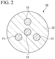
- FIG. 2 is a cross-sectional view showing one example of the multicore fiber in the first embodiment of the present invention.
- the multicore fiber 10 has a plurality of cores 11 and a common cladding 12 covering the periphery of the cores 11.
- the multicore fiber 10 illustrated in FIG. 2 includes a total of four cores 11 where one core 11 is disposed at the center of the multicore fiber 10 and three cores 11 are disposed concentrically around the center core 11.
- Such a multicore fiber 10 can propagate individual optical signals to the respective cores 11.
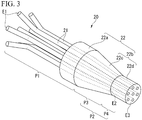
- FIG. 3 is a perspective view showing a fan-in/fan-out device according to the first embodiment of the present invention.
- the fan-in/fan-out device 20 includes a plurality of single-core fibers 21 and a capillary 22, and relay-connects the multicore fiber 10 and a plurality of signal transmission fibers 30. That is, the fan-in/fan-out device 20 causes optical signals propagated through the plurality of signal transmission fibers 30 to be incident on the plurality of cores 11 of the multicore fiber 10 and causes optical signals propagated through the plurality of cores 11 of the multicore fiber 10 to be incident on the plurality of signal transmission fibers 30, respectively.
- FIG. 4 is a cross-sectional view showing an example of a single-core fiber according to the first embodiment of the present invention.
- the single-core fiber 21 includes a core C and a cladding CL covering the periphery of the core C.
- the cladding CL has a lower refractive index than the core C.
- the number of the single-core fibers 21 is greater than the number of cores 11 of the multicore fibers 10, and can be connected to the cores 11 based on a plurality of combinations when the multicore fibers 10 are rotated. With such an arrangement, it is possible to realize an optical device 1 with a small optical loss due to a manufacturing error.
- FIG. 5 is a cross-sectional view showing an example of the arrangement of single-core fibers in the first embodiment of the present invention.
- one single-core fiber 21 (21a) is disposed at the center of the fan-in/fan-out device 20, and six single-core fibers 21 (21b, 21c) are arranged concentrically around the single-core fiber 21a.
- the single-core fibers 21b and the single-core fibers 21c are alternately arranged along the circumferential direction.
- combinations capable of being connected to the plurality of cores 11 are i) a combination of a single-core fiber 21a and three single-core fibers 21b, and ii) a combination of a single-core fiber 21a and three single-core fibers 21c.
- the splice is possible when, for example, the core 11 of the multicore fiber 10 is in a state shown in FIG. 2
- the combination ii) the splice is possible when, for example, the core 11 of the multicore fiber 10 is rotated by 180° from a state shown in FIG. 2 .
- the combination i) and the combination ii) can be referred to as rotationally symmetric (or substantially rotationally symmetric in consideration of manufacturing errors and the like).
- the single-core fibers 21 it is also possible to arrange the single-core fibers 21 so that connection with the core 11 becomes possible in a plurality of combinations when the multicore fiber 10 is moved in parallel in the radial direction.
- the multicore fiber 10 and the fan-in/fan-out device 20 may be connected in a state of being eccentric in the radial direction (state of axial deviation), and the mechanical strength may be reduced.
- the multicore fiber 10 and the fan-in/fan-out device 20 are connected without causing the above-mentioned axial deviation by arranging in rotational symmetry (or substantially rotational symmetry) and the mechanical strength can be increased.
- the arrangement of the single-core fibers 21 be a rotationally symmetrical (or substantially rotationally symmetrical) arrangement as in the present embodiment.
- the single-core fiber 21 has a large diameter portion P1 which is one end side portion, and an elongated portion P2 which is the other end side portion extending in the length direction from the large diameter portion P1.
- the large diameter portion P1 is a portion which is not extended, and an outer diameter thereof is constant in the length direction.
- the end portion E1 of the large diameter portion P1 of the single-core fiber 21 to be connected to the core 11 of the multicore fiber 10 is connected to the end portion E10 of the signal transmission fiber 30 at the connection portion C1.
- the large diameter portion P1 may be fusion-spliced to the signal transmission fiber 30.
- the end portion E1 of the large diameter portion P1 of each of the four single-core fibers 21 is respectively connected to the end portions E10 of each of the four signal transmission fibers 30.
- the end portion E1 of the large diameter portion P1 of the remaining single-core fibers 21 (the single-core fibers 21 which are not connected to the cores 11 of the multicore fiber 10) is not connected to the end portions E10 of the signal transmission fiber 30.
- Such a large diameter portion P1 which is not connected to the end portion E10 of the signal transmission fiber 30 may be cut so as to shorten its length (or not to extend from the capillary 22) as necessary.
- the elongated portion P2 includes a diameter-reduced portion P3 extending from the large diameter portion P1 while reducing the diameter in the length direction, and a small diameter portion P4 extending from the diameter-reduced portion P3.
- the core diameter of the single-core fiber 21 gradually decreases along the extending direction.
- the ratio (minimum outer diameter / maximum outer diameter) of the minimum outer diameter to the maximum outer diameter of the single-core fiber 21 at the diameter-reduced portion P3 may fall into a range of, for example, 1/1.5 to 1/2.5.
- the maximum outer diameter of the diameter-reduced portion P3 may be the same as the outer diameter of the large diameter portion P1.
- the small diameter portion P4 is a portion of a constant diameter which is formed to extend in the same direction from the end portion E2 in the extension direction of the diameter-reduced portion P3.
- the end portion E3 in the extension direction of the small diameter portion P4 is connected to the core 11 (see FIG. 2 ) of the multicore fiber 10 at the connection point C2.
- the small diameter portion P4 may be fusion-spliced to the multicore fiber 10.
- four single-core fibers 21 in the small diameter portion P4 of the seven single-core fibers 21 are connected to the cores 11 of the multicore fiber 10, respectively.
- the outer diameter of the small diameter portion P4 may be the same as the minimum outer diameter of the diameter-reduced portion P3 and may be the same as the outer diameter of the multicore fiber 10.
- the single-core fiber 21 of the fan-in/fan-out device of the present embodiment includes a structure including a large diameter portion P1 and an elongated portion P2, and the elongated portion P2 includes a diameter-reduced portion P3 and a small diameter portion P4.
- the structure can be, one or both of the large diameter portion P1 and the small diameter portion P4 may be omitted.
- the elongated portion P2 is formed of only the diameter-reduced portion P3.
- the capillary 22 holds a plurality of single-core fibers 21 in a substantially bundled state, and is formed of glass or the like.
- the capillary 22 is provided in a portion of or all of the single-core fiber 21 in the length direction.
- the capillary 22 includes a base 22a and an extension portion 22b extending from the base 22a.
- the extension portion 22b includes a tapered portion 22c extending from the base portion 22a while reducing the diameter in the length direction, and a tip portion 22d extending from the tapered portion 22c.
- the base 22a can be formed on a portion of the large diameter portion P1 of the single-core fiber 21.
- the tapered portion 22c and the tip portion 22d are formed at positions corresponding to the diameter-reduced portion P3 and the diameter-reduced portion P4 of the single-core fiber 21, respectively.
- the signal transmission fibers 30 are optical fibers respectively connected to the plurality of cores 11 of the multicore fiber 10 via the fan-in/fan-out device 20.
- the signal transmission fiber 30 transmits an optical signal to be incident on the plurality of cores 11 of the multicore fiber 10 or transmits an optical signal propagated through the plurality of cores 11 of the multicore fiber 10.
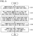
- FIG. 6 is a flowchart showing an example of a method for manufacturing an optical device according to the first embodiment of the present invention. As shown in FIG. 6 , when the manufacture of the optical device 1 is started, the process of manufacturing the fan-in/fan-out device 20 having the plurality of single-core fibers 21 described with reference to FIGS. 1 and 3 (Step S11).
- Step S11 the process that the single-core fiber 21 is inserted in each of a plurality of holes of the cylindrical capillary 22 having the plurality of holes in which the single-core fiber 21 is inserted, and the process of melt-drawing the capillary 22 while partially heating the capillary 22 where the plurality of single-core fibers 21 is inserted therein to form the elongated portion P2 (extension portion 22b) are sequentially performed.
- the holes of the capillary 22 are formed such that the single-core fibers 21 to be inserted are arranged as shown in FIG. 5 .
- the fan-in/fan-out device 20 shown in FIG. 3 is manufactured.
- Step S12 first step.
- an end portion of the multicore fiber 10 and an end portion (end portion E3) of the elongated portion P2 of the fan-in/fan-out device 20 are respectively captured, and one combination of single-core fibers 21 to be connected to the plurality of cores 11 of the multicore fiber 10 is set based on the obtained image. For example, a combination of a single-core fiber 21a and three single-core fibers 21b shown in FIG. 5 is set.
- the end portion of the multicore fiber 10 and the end portion (end portion E3) of the extension portion 22b of the fan-in/fan-out device 20 is brought into a state of being in proximity so that the core of the single-core fiber 21 in the set combination faces the core 11 of the multicore fiber 10. Then, when an optical signal is individually incident from the other end portion of the single-core fiber 21 (single-core fiber 21 disposed so that one end portion faces the core 11 of the multicore fiber 10), the light intensity of the light signal emitted from the opposed core 11 is separately measured.
- another combination of the single-core fibers 21 to be connected to the plurality of cores 11 of the multicore fiber 10 is set.
- a combination of a single-core fiber 21a and three single-core fibers 21c shown in FIG. 5 is set.
- the multicore fiber 10 which is brought into a state of being in proximity to the end portion (end portion E3) of the elongated portion P2 of the fan-in/fan-out device 20, is rotated such that the core of the fiber 21 of the set combination faces the core 11 of the multicore fiber 10.
- the optical signal is again separately incident from the other end of the single-core fiber 21 (single-core fiber 21 disposed so that one end faces the core 11 of the multicore fiber 10), the light intensity of the optical signal emitted from the facing core 11 is separately measured.
- the light intensity emitted from each core 11 of the multicore fiber 10 is measured when the combination of the single-core fiber 21 to be connected to the plurality of cores 11 of the multicore fiber 10 is changed.
- the measured light intensity reflects the coupling loss between the core 11 of the multicore fiber 10 and the single-core fiber 21. For this reason, the coupling loss for each core 11 is determined when the combination of the single-core fibers 21 to be connected to the plurality of cores 11 of the multicore fiber 10 is changed.
- a combination of single-core fibers 21 to be connected to each core 11 of the multicore fiber 10 is selected according to the determined coupling loss (Step S13: second step). For example, the measurement results for each combination of single-core fibers 21 are compared, and a combination of single-core fibers 21 with high intensity of the optical signal emitted from each core 11 and small variation is selected.
- a combination of the single-core fiber 21a and the three single-core fibers 21b shown in FIG. 5 is selected.
- Step S14 the process of connecting the end portion of the multicore fiber 10 and the end portion (end portion E3) of the elongated portion P2 of the fan-in/fan-out device 20 is performed so that the single-core fiber 21 and the core 11 of the multicore fiber 10 of the selected combination are connected.
- the end portion of the multicore fiber 10 and the end portion (end portion E3) of the elongated portion P2 of the fan-in/fan-out device 20 are fusion-spliced such that the combination of the single-core fiber 21a and the three single-core fibers 21b shown in FIG. 5 and the core 11 of the multicore fiber 10 are connected.
- Step S15 the process is performed such that the end portion E10 of the signal transmission fiber 30 is connected to the end portion E1 of the single-core fiber 21 connected to the core 11 of the multicore fiber 10 (Step S15).
- the end portion E10 of the signal transmission fiber 30 may be connected to the end portion E1 of all the single-core fibers 21 after the fan-in/fan-out device 20 is manufactured in Step S11. In such a case, Step S15 is omitted.
- Step S12 optical signals are individually incident from the other end of the single-core fiber 21 (the single-core fiber 21 disposed so that one end faces the core 11 of the multicore fiber 10). Occasionally, the light intensity of the light signal emitted from the opposing core 11 is measured individually. However, conversely to this, optical signals may be made incident from a side of the multicore fiber 10, and optical signals emitted from the other end of the single-core fiber 21 may be individually measured.
- a fan-in/fan-out device 20 is manufactured that has a plurality of single-core fibers 21 arranged so as to enable splicing with the core 11 in a plurality of combinations when the multicore fiber 10 is rotated, and the coupling loss for each core 11 is determined while changing the combination of the single-core fibers 21 to be connected to the core 11 of the multicore fiber 10. Then, according to the result, one combination of the single-core fibers 21 is selected, and the end portion of the multicore fiber 10 and the end portion E3 of the elongated portion P2 of the fan-in/fan-out device 20 is connected so that the single-core fiber 21 and the core 11 of the multicore fiber 10 of the selected combination are connected.
- the optical device 1 can be manufactured with a small optical loss due to the manufacturing error.
- the example of selecting the combination of the single-core fibers 21 in which the coupling loss decreases is described.
- the combination of the single-core fibers 21 in which the variation of the coupling loss decreases may be selected.
- FIGS. 7A and 7B are cross-sectional views showing an example of a multicore fiber and a fan-in/fan-out device according to the second embodiment of the present invention.
- FIG.7A is a cross-sectional view of the multicore fiber 10 at the connection point C2
- FIG. 7B is a cross-sectional view of the fan-in/fan-out device 20 at the connection point C2.
- the optical device of this embodiment is manufactured basically through the steps shown in the flow chart of FIG. 6 as in the optical device of the first embodiment.
- the configuration of the fan-in/fan-out device 20 manufactured in Step S11 in FIG. 6 and the method of obtaining the coupling loss in Step S12 in FIG. 6 are different from those in the first embodiment.
- the distance between the single-core fibers 21 is different for each combination of single-core fibers 21 to be connected to the core 11 of the multicore fiber 10.
- the coupling loss is estimated from an image obtained by capturing the end portion of the multicore fiber 10 and the fan-in/fan-out device 20.
- the combination that can be connected to the plurality of cores 11 when the multicore fiber 10 is rotated is the same as that of the first embodiment. That is, i) a combination of a single-core fiber 21a and three single-core fibers 21b, and ii) a combination of a single-core fiber 21a and three single-core fibers 21c.
- the inter-core distance (inter-core distance between the single-core fiber 21a and the three single-core fibers 21b) of the combination i) is set to r1
- the inter-core distance (inter-core distance between the core fiber 21a and the three single-core fibers 21c) of the combination ii) is set to r2.
- the inter-core distance (distance between the cores 11) of the multicore fiber 10 is set to r3.
- D is the core diameter
- ⁇ is the positional displacement amount between the cores to be connected.
- steps S13 to S15 in FIG. 6 are sequentially performed.
- the end portion of the multicore fiber 10 and the end portion (end portion E3) of the fan-in/fan-out device 20 are fusion-spliced so that the combination of the single-core fiber 21a and the three single-core fibers 21b shown in FIG. 7B and the core 11 of the multicore fiber 10 are connected.
- the end portion of the multicore fiber 10 and the end portion (end portion E3) of the fan-in/fan-out device 20 are fusion-spliced so that the combination of the single-core fiber 21a and the three single-core fibers 21c shown in FIG. 7B and the core 11 of the multicore fiber 10 are connected.
- the coupling loss is determined.
- an optical signal may be made incident on the multicore fiber 10 and the fan-in/fan-out device 20 to determine the coupling loss.
- the inter-core distance indicates a distance between the core (core 11, single-core fiber 21a) disposed at the center of the multicore fiber 10 or the fan-in/fan-out device 20 and the other cores (core 11, single-core 21b or single-core fiber 21c). If there is no centrally placed core, the inter-core distance may be a distance from the center of the multicore fiber 10 or the fan-in/fan-out device 20, or a distance between two adjacent cores.
- a combination of the single-core fibers 21 where the coupling loss or the variation of the coupling loss is small can be selected and connected to the core 11 of the multicore fiber 10. For this reason, it is possible to manufacture an optical device with a small optical loss due to a manufacturing error.
- FIGS. 8A and 8B are cross-sectional views showing an example of a multicore fiber and a fan-in/fan-out device according to a third embodiment of the present invention.
- FIG. 8A is a cross-sectional view of the multicore fiber 10 at the connection point C2
- FIG. 8B is a cross-sectional view of the fan-in/fan-out device 20 at the connection point C2.
- the configuration of the fan-in/fan-out device 20 manufactured in Step S11 in FIG. 6 and the method of obtaining the coupling loss in Step S12 in FIG. 6 are different from those in the first embodiment.
- the diameter of the single-core fiber 21 is different for each combination of the single-core fibers 21 to be connected to the core 11 of the multicore fiber 10.
- the coupling loss is estimated from an image obtained by capturing the end portions of the multicore fiber 10 and the fan-in/fan-out device 20.
- the loss due to the difference in the core diameter can be estimated, for example, by using the proportion to the square of the core diameter ratio when light is transmitted from the larger core diameter to the smaller core diameter.
- the combinations that can be connected to the plurality of cores 11 when the multicore fiber 10 is rotated are the same as that of the first embodiment. That is, the combinations are: i) a combination of single-core fiber 21a and three single-core fibers 21b, and ii) a combination of single-core fiber 21a and three single-core fibers 21c.
- the core diameter (core diameter of the three single-core fibers 21b) in the combination i) is set to a1
- the core diameter (core diameter of the three single-core fibers 21c) in the combination ii) is set to a2.
- the diameter of the single-core fiber 21a common to the combinations i) and ii) can be arbitrarily set, but is set to, for example, (a1+a2)/2.
- the core diameter a3 of the core 11 of the multicore fiber 10 is set.
- the coupling loss for each core 11 of the multicore fiber 10 shown in FIG. 8A and the fan-in/fan-out device 20 shown in FIG. 8B As in the second embodiment, first, the end portion of the multicore fiber 10 and the end portion E2 of the fan-in/fan-out device 20 are captured. Next, the difference between the core diameter of the core 11 of the multicore fiber 10 and the core diameter of the single-core fiber 21 of the fan-in/fan-out device 20 is determined from each image obtained by capturing. Then, the coupling loss for each core 11 is estimated based on the difference.
- steps S13 to S15 in FIG. 6 are sequentially performed.
- the end portion of the multicore fiber 10 and the end portion (end portion E3) of the fan-in/fan-out device 20 are fusion-spliced so that the combination of the single-core fiber 21a and the three single-core fibers 21b shown in FIG. 8B and the core 11 of the multicore fiber 10 are connected.
- the end portion of the multicore fiber 10 and the end portion (end portion E3) of the fan-in/fan-out device 20 are fusion-spliced so that the combination of the single-core fiber 21a and the three single-core fibers 21c shown in FIG. 8B and the core 11 of the multicore fiber 10 are connected.
- the loss is estimated using the core diameter; however, a mode field diameter may be used instead.
- the mode field diameter can be measured by an optical characteristic measurement method (for example, a far-field scanning method, a near-field scanning method, or the like) at the end portion E2 of the fan-in/fan-out device 20.
- the coupling loss L can be expressed by the following equation (2) in consideration of the positional displacement amount by the image observation.
- w1 and w2 are the respective mode field diameters (corresponding to the above-mentioned core diameters a1 and a2)
- ⁇ is the positional displacement amount between the cores.
- the coupling loss is determined.
- an optical signal may be made incident on the multicore fiber 10 and the fan-in/fan-out device 20 to determine the coupling loss.
- a combination of the single-core fibers 21 where the coupling loss or the variation of the coupling loss is small can be selected and connected to the core 11 of the multicore fiber 10. For this reason, it is possible to manufacture an optical device with a small optical loss due to a manufacturing error.
- the first to third embodiments described above may be combined appropriately.
- the method of determining the coupling loss described in the second and third embodiments described above may be applied to the first embodiment.
- the distance between the single-core fibers 21 may be different, and also the core diameter and the mode field diameter may be different.
- FIGS. 9A to 10B are cross-sectional views showing another examples of a multicore fiber and a fan-in/fan-out device.
- FIGS. 9A, 9B , and 10A are cross-sectional views at the connection point C2 of the multicore fiber 10
- FIG. 10B is a cross-sectional view at the connection point C2 of the fan-in/fan-out device 20.
- the multicore fiber 10 shown in FIG. 9A has two cores 11 arranged concentrically around the center of the multicore fiber 10.
- a fan-in/fan-out device 20 shown in FIG. 9B is used for example.
- four single-core fibers 21 (21b, 21c) are arranged concentrically around the center of the fan-in/fan-out device 20.
- the single-core fibers 21b and the single-core fibers 21c are alternately arranged along the circumferential direction.
- combinations that can be connected to the plurality of cores 11 are: iii) a combination of two single-core fibers 21b, and iv) a combination of two single-core fibers 21c.
- the combination iii) is possible, for example, in a case of the core 11 of the multicore fiber 10 shown in FIG. 9A
- the combination iv) is possible, for example, when the core 11 of the multicore fiber 10 shown in FIG. 9A is rotated by 90°.
- the multicore fiber 10 shown in FIG. 10A has three cores 11 arranged concentrically around the center of the multicore fiber 10.
- a fan-in/fan-out device 20 shown in FIG. 10B is used for example.
- six single-core fibers 21 (21b, 21c) are arranged concentrically around the center of the fan-in/fan-out device 20.
- the single-core fibers 21b and the single-core fibers 21c are alternately arranged along the circumferential direction.
- the combinations that can be connected to the plurality of cores 11 when the multicore fiber 10 is rotated are: v) a combination of three single-core fibers 21b, and vi) a combination of three single-core fibers 21c.
- the combination v) is possible, for example, in a case of the core 11 of the multicore fiber 10 shown in FIG. 10A
- the combination vi) is possible, for example, when the core 11 of the multicore fiber 10 shown in FIG. 10A is rotated by 180°.
Landscapes
- Physics & Mathematics (AREA)
- Optics & Photonics (AREA)
- General Physics & Mathematics (AREA)
- Engineering & Computer Science (AREA)
- Plasma & Fusion (AREA)
- Chemical & Material Sciences (AREA)
- Analytical Chemistry (AREA)
- Optical Couplings Of Light Guides (AREA)
- Optical Fibers, Optical Fiber Cores, And Optical Fiber Bundles (AREA)
Abstract
Description
- The present invention relates to a method for manufacturing an optical device
Priority is claimed on Japanese Patent Application No.2017-126964, filed June 29, 2017 - In recent years, research and development of a multicore fiber (MCF), which is an optical fiber having a structure including a plurality of cores and a common cladding covering the periphery of the plurality of cores, has been actively conducted. Multicore fibers are attracting attention as transmission media capable of increasing the transmission capacity of an optical communication system because they can transmit individual information to each core.
- In addition, a multicore fiber may be used as an optical fiber sensor (for example, an optical fiber sensor of an FBG type). An optical fiber sensor measures various physical quantities (for example, stress, strain, temperature, and the like) using an optical fiber (including a multicore fiber) as a sensor. In the above-mentioned FBG-type optical fiber sensor, a Fiber Bragg Grating (FBG) is formed in the core of an optical fiber (including a multicore fiber). By using the reflection characteristics that the FBG changes according to the surrounding environment, distributions of various physical quantities in the length direction of the optical fiber are measured.
- A fan-in/fan-out device is connected to such a multicore fiber as an input/output device for connecting each core and an external optical fiber. The fan-in/fan-out device is manufactured such that a plurality of holes are formed in a glass preform (capillary) where a single mode fiber is inserted into a hole, a single mode fiber is inserted in each of the plurality of holes formed in the glass preform, and an elongated portion (portion elongated while the diameter is reduced) is formed by fusing and elongating a portion of the glass preform in which the single mode fiber is inserted while heating. Each of the above-described single mode fiber is an optical fiber, a plurality of which is provided in the fan-in/fan-out device, and an external optical fiber is connected to one end of the single mode fiber and one core of a multicore fiber is connected to the other end of the same.
-
Patent Document 1 described below discloses a shape sensing technique for measuring a shape of the optical fiber sensor (a shape of an object where the optical fiber sensor is attached) by an Optical Frequency Domain Reflectometry (OFDR) method using an FBG type optical fiber sensor using a multicore fiber. In addition,Patent Documents 2 to 4 described below disclose examples of fan-in/fan-out devices that connect each core of a multicore fiber to an external optical fiber. -
- [Patent Document 1]
US Patent No. 7781724 - [Patent Document 2] Japanese Patent No.
5782104 - [Patent Document 3] Japanese Unexamined Patent Application, First Publication No.
2015-1673 - [Patent Document 4] Japanese Unexamined Patent Application, First Publication No.
2015-152774 - It is desirable that an optical device in which a fan-in/fan-out device is connected (fused) to a multicore fiber has a small light loss. However, in such an optical device, the occurrence of light loss is inevitable due to the following causes.
- For example, the positional deviation of the hole formed in the glass preform, variation in inter-core distance in an elongating portion (due to the positional deviation in the hole of single-core fiber generated at the time of melting and elongating),and misalignment of the core in the elongated portion (caused by variation in a diameter reduction ratio)
- For example, there is a loss due to a mismatch between the core diameter of the elongated portion and the core diameter of the multicore fiber fused to the elongated portion. Such a mismatch essentially occurs in the manufacture of a fan-in/fan-out device having an elongated portion, and occurs due to the variation of the diameter reduction ratio of the elongated portion when melting and elongating a glass preform in which a single-core fiber is inserted.
- The present invention has been made in view of the above circumstances, and provides a method for manufacturing an optical device capable of manufacturing an optical device having a small optical loss due to a manufacturing error.
- A first aspect of the present invention is a method for manufacturing an optical device including, a multicore fiber comprising a plurality of cores, and a fan-in /fan-out device including a plurality of single-core fibers arranged so as to be connectable to the cores respectively based on a plurality of combinations when the multicore fiber is rotated, the method comprising: a first step of determining an optical loss for each core while changing a combination of the single-core fibers of the fan-in/fan-out device to be connected to the cores of the multicore fiber; and a second step of selecting one combination of the single-core fibers of the fan-in/fan-out device to be connected to the cores of the multicore fiber according to a result of the first step, and connecting an end portion of the multicore fiber and an end portion of the fan-in/fan-out device so that the single-core fibers and the core of the multicore fibers of the selected combination are connected.
- A second aspect of the present invention is the method for manufacturing an optical device according to the first aspect, in which in the first step, the optical loss is determined by measuring an intensity of an optical signal for each core input from either one of the multicore fiber or the fan-in/fan-out device and output from another one of the multicore fiber or the fan-in/fan-out device in a state where the end portion of the multicore fiber and the end portion of the fan-in/fan-out device are in proximity.
- A third aspect of the present invention is the method for manufacturing an optical device according to the first aspect, in which in the first step, in which in the first step, the optical loss is determined by determining a difference between a distance of the cores of the multicore fiber and a distance of the single core fibers of the fan-in/fan-out device from respective images obtained by capturing the end portion of the multicore fiber and the end portion of the fan-in/fan-out device.
- A fourth aspect of the present invention is the method for manufacturing an optical device according to the first aspect, in which in the first step, the optical loss is determined by determining a difference between a core diameter of the multicore fiber and a core diameter of the single-core fibers of the fan-in/fan-out device from respective images obtained by capturing the end portion of the multicore fiber and the end portion of the fan-in/fan-out device.
- A fifth aspect of the present invention is the method for manufacturing an optical device according to the first aspect, in which in the second step, the optical loss is determined by determining a difference between a mode field diameter of the multicore fiber and a mode field diameter of the single-core fibers of the fan-in/fan-out device obtained by a method of measuring optical characteristics at the end portion of the multicore fiber and the end portion of the fan-in/fan-out device.
- A sixth aspect of the present invention is the method for manufacturing an optical device according to any one of the first to fifth aspects, in which a distance between the single core fibers of the fan-in/fan-out device is different for each combination of the single-core fibers of the fan-in/fan-out device that are connected to the core of the multicore fiber.
- A seventh aspect of the present invention is the method for manufacturing an optical device according to any one of the first to sixth aspects, in which a core diameter of the single core fiber of the fan-in/fan-out device is different for each combination of the single-core fibers of the fan-in/fan-out device that are connected to the core of the multicore fiber.
- According to the above aspects of the present invention, it is possible to manufacture an optical device having a small light loss due to a manufacturing error.
-
-
FIG. 1 is a schematic view showing an optical device of the first embodiment of the present invention. -
FIG. 2 is a cross-sectional view showing one example of a multicore fiber of the first embodiment of the present invention. -
FIG. 3 is a perspective view showing a fan-in/fan-out device of the first embodiment of the present invention. -
FIG. 4 is a cross-sectional view showing one example of a single-core fiber of the first embodiment of the present invention. -
FIG. 5 is a cross-sectional view showing one example of an arrangement of a single-core fiber of the first embodiment of the present invention. -
FIG. 6 is a flowchart showing one example of a manufacturing method of the optical device of the first embodiment of the present invention. -
FIG. 7A is a cross-sectional view showing one example of a multicore fiber and a fan-in/fan-out device of the second embodiment of the present invention. -
FIG. 7B is a cross-sectional view showing one example of a multicore fiber and a fan-in/fan-out device of the second embodiment of the present invention. -
FIG. 8A is a cross-sectional view showing one example of a multicore fiber and a fan-in/fan-out device of the third embodiment of the present invention. -
FIG. 8B is a cross-sectional view showing one example of a multicore fiber and a fan-in/fan-out device of the third embodiment of the present invention. -
FIG. 9A is a cross-sectional view showing another example of a multicore fiber and a fan-in/fan-out device. -
FIG. 9B is a cross-sectional view showing another example of a multicore fiber and a fan-in/fan-out device. -
FIG. 10A is a cross-sectional view showing another example of a multicore fiber and a fan-in/fan-out device. -
FIG. 10B is a cross-sectional view showing another example of a multicore fiber and a fan-in/fan-out device. - Hereinafter, a method for manufacturing an optical device according to an embodiment of the present invention will be described in detail with reference to the drawings. In the drawings referred to in the following, in order to facilitate understanding, the scale of dimensions of each member is appropriately changed and illustrated as necessary.
-
FIG. 1 is a schematic view showing an optical device of the first embodiment of the present invention. As shown inFIG. 1 , theoptical device 1 of the present embodiment includes amulticore fiber 10, a fan-in/fan-outdevice 20, and a plurality ofsignal transmission fibers 30. Such anoptical device 1 makes an optical signal propagated through thesignal transmission fiber 30 enter themulticore fiber 10 via the fan-in/fan-outdevice 20 or makes an optical signal propagated through themulticore fiber 10 enter thesignal transmission fiber 30 through the fan-in/fan-outdevice 20. Theoptical device 1 shown inFIG. 1 is applicable to an optical fiber sensor using, for example, amulticore fiber 10 as a sensor. -
FIG. 2 is a cross-sectional view showing one example of the multicore fiber in the first embodiment of the present invention. As shown inFIG. 2 , themulticore fiber 10 has a plurality ofcores 11 and acommon cladding 12 covering the periphery of thecores 11. Themulticore fiber 10 illustrated inFIG. 2 includes a total of fourcores 11 where onecore 11 is disposed at the center of themulticore fiber 10 and threecores 11 are disposed concentrically around thecenter core 11. Such amulticore fiber 10 can propagate individual optical signals to therespective cores 11. -
FIG. 3 is a perspective view showing a fan-in/fan-out device according to the first embodiment of the present invention. As shown inFIGS. 1 and3 , the fan-in/fan-outdevice 20 includes a plurality of single-core fibers 21 and a capillary 22, and relay-connects themulticore fiber 10 and a plurality ofsignal transmission fibers 30. That is, the fan-in/fan-outdevice 20 causes optical signals propagated through the plurality ofsignal transmission fibers 30 to be incident on the plurality ofcores 11 of themulticore fiber 10 and causes optical signals propagated through the plurality ofcores 11 of themulticore fiber 10 to be incident on the plurality ofsignal transmission fibers 30, respectively. -
FIG. 4 is a cross-sectional view showing an example of a single-core fiber according to the first embodiment of the present invention. As shown inFIG. 4 , the single-core fiber 21 includes a core C and a cladding CL covering the periphery of the core C. The cladding CL has a lower refractive index than the core C. The number of the single-core fibers 21 is greater than the number ofcores 11 of themulticore fibers 10, and can be connected to thecores 11 based on a plurality of combinations when themulticore fibers 10 are rotated. With such an arrangement, it is possible to realize anoptical device 1 with a small optical loss due to a manufacturing error. -
FIG. 5 is a cross-sectional view showing an example of the arrangement of single-core fibers in the first embodiment of the present invention. In the fan-in/fan-outdevice 20 illustrated inFIG. 5 , one single-core fiber 21 (21a) is disposed at the center of the fan-in/fan-outdevice 20, and six single-core fibers 21 (21b, 21c) are arranged concentrically around the single-core fiber 21a. In the example shown inFIG. 5 , the single-core fibers 21b and the single-core fibers 21c are alternately arranged along the circumferential direction. - In the example shown in
FIG. 5 , when themulticore fiber 10 is rotated, combinations capable of being connected to the plurality ofcores 11 are i) a combination of a single-core fiber 21a and three single-core fibers 21b, and ii) a combination of a single-core fiber 21a and three single-core fibers 21c. In the combination i),the splice is possible when, for example, thecore 11 of themulticore fiber 10 is in a state shown inFIG. 2 , and in the combination ii),the splice is possible when, for example, thecore 11 of themulticore fiber 10 is rotated by 180° from a state shown inFIG. 2 . The combination i) and the combination ii) can be referred to as rotationally symmetric (or substantially rotationally symmetric in consideration of manufacturing errors and the like). - In addition, it is also possible to arrange the single-
core fibers 21 so that connection with thecore 11 becomes possible in a plurality of combinations when themulticore fiber 10 is moved in parallel in the radial direction. However, in the case of such an arrangement, themulticore fiber 10 and the fan-in/fan-outdevice 20 may be connected in a state of being eccentric in the radial direction (state of axial deviation), and the mechanical strength may be reduced. On the other hand, as in the present embodiment, themulticore fiber 10 and the fan-in/fan-outdevice 20 are connected without causing the above-mentioned axial deviation by arranging in rotational symmetry (or substantially rotational symmetry) and the mechanical strength can be increased. For this reason, it is desirable that the arrangement of the single-core fibers 21 be a rotationally symmetrical (or substantially rotationally symmetrical) arrangement as in the present embodiment. - As shown in
FIGS. 1 and3 , the single-core fiber 21 has a large diameter portion P1 which is one end side portion, and an elongated portion P2 which is the other end side portion extending in the length direction from the large diameter portion P1. The large diameter portion P1 is a portion which is not extended, and an outer diameter thereof is constant in the length direction. Among the single-core fibers 21, the end portion E1 of the large diameter portion P1 of the single-core fiber 21 to be connected to thecore 11 of themulticore fiber 10 is connected to the end portion E10 of thesignal transmission fiber 30 at the connection portion C1. The large diameter portion P1 may be fusion-spliced to thesignal transmission fiber 30. In the example shown inFIG. 1 , the end portion E1 of the large diameter portion P1 of each of the four single-core fibers 21 is respectively connected to the end portions E10 of each of the foursignal transmission fibers 30. - The end portion E1 of the large diameter portion P1 of the remaining single-core fibers 21 (the single-
core fibers 21 which are not connected to thecores 11 of the multicore fiber 10) is not connected to the end portions E10 of thesignal transmission fiber 30. Such a large diameter portion P1 which is not connected to the end portion E10 of thesignal transmission fiber 30 may be cut so as to shorten its length (or not to extend from the capillary 22) as necessary. - The elongated portion P2 includes a diameter-reduced portion P3 extending from the large diameter portion P1 while reducing the diameter in the length direction, and a small diameter portion P4 extending from the diameter-reduced portion P3. At the diameter-reduced portion P3, the core diameter of the single-
core fiber 21 gradually decreases along the extending direction. The ratio (minimum outer diameter / maximum outer diameter) of the minimum outer diameter to the maximum outer diameter of the single-core fiber 21 at the diameter-reduced portion P3 may fall into a range of, for example, 1/1.5 to 1/2.5. The maximum outer diameter of the diameter-reduced portion P3 may be the same as the outer diameter of the large diameter portion P1. - The small diameter portion P4 is a portion of a constant diameter which is formed to extend in the same direction from the end portion E2 in the extension direction of the diameter-reduced portion P3. The end portion E3 in the extension direction of the small diameter portion P4 is connected to the core 11 (see
FIG. 2 ) of themulticore fiber 10 at the connection point C2. The small diameter portion P4 may be fusion-spliced to themulticore fiber 10. In the present embodiment, four single-core fibers 21 in the small diameter portion P4 of the seven single-core fibers 21 are connected to thecores 11 of themulticore fiber 10, respectively. The outer diameter of the small diameter portion P4 may be the same as the minimum outer diameter of the diameter-reduced portion P3 and may be the same as the outer diameter of themulticore fiber 10. - The single-
core fiber 21 of the fan-in/fan-out device of the present embodiment includes a structure including a large diameter portion P1 and an elongated portion P2, and the elongated portion P2 includes a diameter-reduced portion P3 and a small diameter portion P4. However, the structure can be, one or both of the large diameter portion P1 and the small diameter portion P4 may be omitted. When there is no small diameter portion P4 the elongated portion P2 is formed of only the diameter-reduced portion P3. - As shown in
FIG. 3 , the capillary 22 holds a plurality of single-core fibers 21 in a substantially bundled state, and is formed of glass or the like. The capillary 22 is provided in a portion of or all of the single-core fiber 21 in the length direction. The capillary 22 includes abase 22a and anextension portion 22b extending from thebase 22a. Theextension portion 22b includes a taperedportion 22c extending from thebase portion 22a while reducing the diameter in the length direction, and atip portion 22d extending from the taperedportion 22c. Thebase 22a can be formed on a portion of the large diameter portion P1 of the single-core fiber 21. The taperedportion 22c and thetip portion 22d are formed at positions corresponding to the diameter-reduced portion P3 and the diameter-reduced portion P4 of the single-core fiber 21, respectively. - The
signal transmission fibers 30 are optical fibers respectively connected to the plurality ofcores 11 of themulticore fiber 10 via the fan-in/fan-outdevice 20. Thesignal transmission fiber 30 transmits an optical signal to be incident on the plurality ofcores 11 of themulticore fiber 10 or transmits an optical signal propagated through the plurality ofcores 11 of themulticore fiber 10. -
FIG. 6 is a flowchart showing an example of a method for manufacturing an optical device according to the first embodiment of the present invention. As shown inFIG. 6 , when the manufacture of theoptical device 1 is started, the process of manufacturing the fan-in/fan-outdevice 20 having the plurality of single-core fibers 21 described with reference toFIGS. 1 and3 (Step S11). - In Step S11, the process that the single-
core fiber 21 is inserted in each of a plurality of holes of thecylindrical capillary 22 having the plurality of holes in which the single-core fiber 21 is inserted, and the process of melt-drawing the capillary 22 while partially heating the capillary 22 where the plurality of single-core fibers 21 is inserted therein to form the elongated portion P2 (extension portion 22b) are sequentially performed. The holes of the capillary 22 are formed such that the single-core fibers 21 to be inserted are arranged as shown inFIG. 5 . Thus, the fan-in/fan-outdevice 20 shown inFIG. 3 is manufactured. - Next, while changing the combination of the single-
core fibers 21 to be connected to each of the plurality ofcores 11 of themulticore fiber 10, a step of obtaining the coupling loss for each core 11 is performed (Step S12: first step). In Step S12, first, an end portion of themulticore fiber 10 and an end portion (end portion E3) of the elongated portion P2 of the fan-in/fan-outdevice 20 are respectively captured, and one combination of single-core fibers 21 to be connected to the plurality ofcores 11 of themulticore fiber 10 is set based on the obtained image. For example, a combination of a single-core fiber 21a and three single-core fibers 21b shown inFIG. 5 is set. - When the setting described above is completed, the end portion of the
multicore fiber 10 and the end portion (end portion E3) of theextension portion 22b of the fan-in/fan-outdevice 20 is brought into a state of being in proximity so that the core of the single-core fiber 21 in the set combination faces thecore 11 of themulticore fiber 10. Then, when an optical signal is individually incident from the other end portion of the single-core fiber 21 (single-core fiber 21 disposed so that one end portion faces thecore 11 of the multicore fiber 10), the light intensity of the light signal emitted from the opposedcore 11 is separately measured. - Subsequently, another combination of the single-
core fibers 21 to be connected to the plurality ofcores 11 of themulticore fiber 10 is set. For example, a combination of a single-core fiber 21a and three single-core fibers 21c shown inFIG. 5 is set. When the setting is completed, for example, themulticore fiber 10, which is brought into a state of being in proximity to the end portion (end portion E3) of the elongated portion P2 of the fan-in/fan-outdevice 20, is rotated such that the core of thefiber 21 of the set combination faces thecore 11 of themulticore fiber 10. Then, when the optical signal is again separately incident from the other end of the single-core fiber 21 (single-core fiber 21 disposed so that one end faces thecore 11 of the multicore fiber 10), the light intensity of the optical signal emitted from the facingcore 11 is separately measured. - Based on the above, the light intensity emitted from each core 11 of the
multicore fiber 10 is measured when the combination of the single-core fiber 21 to be connected to the plurality ofcores 11 of themulticore fiber 10 is changed. The measured light intensity reflects the coupling loss between the core 11 of themulticore fiber 10 and the single-core fiber 21. For this reason, the coupling loss for each core 11 is determined when the combination of the single-core fibers 21 to be connected to the plurality ofcores 11 of themulticore fiber 10 is changed. - Next, a combination of single-
core fibers 21 to be connected to eachcore 11 of themulticore fiber 10 is selected according to the determined coupling loss (Step S13: second step). For example, the measurement results for each combination of single-core fibers 21 are compared, and a combination of single-core fibers 21 with high intensity of the optical signal emitted from each core 11 and small variation is selected. Here, it is assumed that a combination of the single-core fiber 21a and the three single-core fibers 21b shown inFIG. 5 is selected. - Next, the process of connecting the end portion of the
multicore fiber 10 and the end portion (end portion E3) of the elongated portion P2 of the fan-in/fan-outdevice 20 is performed so that the single-core fiber 21 and thecore 11 of themulticore fiber 10 of the selected combination are connected (Step S14: second step). For example, the end portion of themulticore fiber 10 and the end portion (end portion E3) of the elongated portion P2 of the fan-in/fan-outdevice 20 are fusion-spliced such that the combination of the single-core fiber 21a and the three single-core fibers 21b shown inFIG. 5 and thecore 11 of themulticore fiber 10 are connected. - When the process described above is completed, the process is performed such that the end portion E10 of the
signal transmission fiber 30 is connected to the end portion E1 of the single-core fiber 21 connected to thecore 11 of the multicore fiber 10 (Step S15). The end portion E10 of thesignal transmission fiber 30 may be connected to the end portion E1 of all the single-core fibers 21 after the fan-in/fan-outdevice 20 is manufactured in Step S11. In such a case, Step S15 is omitted. - In the embodiment described above, in Step S12, optical signals are individually incident from the other end of the single-core fiber 21 (the single-
core fiber 21 disposed so that one end faces thecore 11 of the multicore fiber 10). Occasionally, the light intensity of the light signal emitted from the opposingcore 11 is measured individually. However, conversely to this, optical signals may be made incident from a side of themulticore fiber 10, and optical signals emitted from the other end of the single-core fiber 21 may be individually measured. - As described above, in the present embodiment, a fan-in/fan-out
device 20 is manufactured that has a plurality of single-core fibers 21 arranged so as to enable splicing with the core 11 in a plurality of combinations when themulticore fiber 10 is rotated, and the coupling loss for each core 11 is determined while changing the combination of the single-core fibers 21 to be connected to thecore 11 of themulticore fiber 10. Then, according to the result, one combination of the single-core fibers 21 is selected, and the end portion of themulticore fiber 10 and the end portion E3 of the elongated portion P2 of the fan-in/fan-outdevice 20 is connected so that the single-core fiber 21 and thecore 11 of themulticore fiber 10 of the selected combination are connected. - Thus, in the present embodiment, among the combinations of the plurality of single-
core fibers 21 that can be connected to thecore 11 of themulticore fiber 10, the combination of the single-core fibers 21 with small coupling loss is selected to connect to thecore 11 of themulticore fiber 10. Therefore, theoptical device 1 can be manufactured with a small optical loss due to the manufacturing error. - In the embodiment described above, the example of selecting the combination of the single-
core fibers 21 in which the coupling loss decreases is described. However, the combination of the single-core fibers 21 in which the variation of the coupling loss decreases may be selected. By selecting such a combination, variations in intensity among the cores can be reduced and optical signals with uniform intensity can be obtained which is desirable from the point of view of a Signal to Noise (S/N) ratio. -
FIGS. 7A and 7B are cross-sectional views showing an example of a multicore fiber and a fan-in/fan-out device according to the second embodiment of the present invention.FIG.7A is a cross-sectional view of themulticore fiber 10 at the connection point C2, andFIG. 7B is a cross-sectional view of the fan-in/fan-outdevice 20 at the connection point C2. - The optical device of this embodiment is manufactured basically through the steps shown in the flow chart of
FIG. 6 as in the optical device of the first embodiment. However, in the present embodiment, the configuration of the fan-in/fan-outdevice 20 manufactured in Step S11 inFIG. 6 and the method of obtaining the coupling loss in Step S12 inFIG. 6 are different from those in the first embodiment. In particular, in the fan-in/fan-outdevice 20 manufactured in the present embodiment, the distance between the single-core fibers 21 is different for each combination of single-core fibers 21 to be connected to thecore 11 of themulticore fiber 10. Furthermore, in the present embodiment, without making an optical signal incident on themulticore fiber 10 and the fan-in/fan-outdevice 20, the coupling loss is estimated from an image obtained by capturing the end portion of themulticore fiber 10 and the fan-in/fan-outdevice 20. - In the fan-in/fan-out
device 20 of the present embodiment, the combination that can be connected to the plurality ofcores 11 when themulticore fiber 10 is rotated is the same as that of the first embodiment. That is, i) a combination of a single-core fiber 21a and three single-core fibers 21b, and ii) a combination of a single-core fiber 21a and three single-core fibers 21c. - As shown in
FIG. 7B , the inter-core distance (inter-core distance between the single-core fiber 21a and the three single-core fibers 21b) of the combination i) is set to r1, and the inter-core distance (inter-core distance between thecore fiber 21a and the three single-core fibers 21c) of the combination ii) is set to r2. As shown inFIG. 7A , the inter-core distance (distance between the cores 11) of themulticore fiber 10 is set to r3. - When obtaining the coupling loss of each core 11 of the
multicore fiber 10 shown inFIG. 7A and the fan-in/fan-outdevice 20 shown inFIG. 7B , first, the end portion of themulticore fiber 10 and the end portion E2 of the fan-in/fan-outdevice 20 are captured. Next, the difference between the distance between thecores 11 of themulticore fiber 10 and the distance between the single-core fibers 21 of the fan-in/fan-outdevice 20 is determined from the respective images obtained by capturing. Then, the coupling loss for each core 11 is estimated based on the difference. In the case of step index type fiber, for example, the following equation (1) can be used to estimate the coupling loss.
(Equation 1)
- In the equation (1) described above, D is the core diameter, and σ is the positional displacement amount between the cores to be connected.
- When the coupling loss for each core 11 is determined, for example, steps S13 to S15 in
FIG. 6 are sequentially performed. For example, when the relationship |r3-r1|≤|r3-r2| is satisfied, the end portion of themulticore fiber 10 and the end portion (end portion E3) of the fan-in/fan-outdevice 20 are fusion-spliced so that the combination of the single-core fiber 21a and the three single-core fibers 21b shown inFIG. 7B and thecore 11 of themulticore fiber 10 are connected. On the other hand, when the relationship of |r3-r1|>|r3-r2| is satisfied, the end portion of themulticore fiber 10 and the end portion (end portion E3) of the fan-in/fan-outdevice 20 are fusion-spliced so that the combination of the single-core fiber 21a and the three single-core fibers 21c shown inFIG. 7B and thecore 11 of themulticore fiber 10 are connected. - In the present embodiment, based on an image obtained by capturing the end portion of the
multicore fiber 10 and the fan-in/fan-outdevice 20 without making the optical signal incident on themulticore fiber 10 and the fan-in/fan-outdevice 20, the coupling loss is determined. However, as in the first embodiment, an optical signal may be made incident on themulticore fiber 10 and the fan-in/fan-outdevice 20 to determine the coupling loss. - Further, in the embodiment described above, the inter-core distance indicates a distance between the core (
core 11, single-core fiber 21a) disposed at the center of themulticore fiber 10 or the fan-in/fan-outdevice 20 and the other cores (core 11, single-core 21b or single-core fiber 21c). If there is no centrally placed core, the inter-core distance may be a distance from the center of themulticore fiber 10 or the fan-in/fan-outdevice 20, or a distance between two adjacent cores. - As described above, also in the present embodiment as in the first embodiment, among a plurality of combinations of the single-
core fibers 21 that can be connected to thecore 11 of themulticore fiber 10, a combination of the single-core fibers 21 where the coupling loss or the variation of the coupling loss is small can be selected and connected to thecore 11 of themulticore fiber 10. For this reason, it is possible to manufacture an optical device with a small optical loss due to a manufacturing error. -
FIGS. 8A and 8B are cross-sectional views showing an example of a multicore fiber and a fan-in/fan-out device according to a third embodiment of the present invention.FIG. 8A is a cross-sectional view of themulticore fiber 10 at the connection point C2, andFIG. 8B is a cross-sectional view of the fan-in/fan-outdevice 20 at the connection point C2. - As in the optical device of the second embodiment, in the optical device of the present embodiment, the configuration of the fan-in/fan-out
device 20 manufactured in Step S11 inFIG. 6 and the method of obtaining the coupling loss in Step S12 inFIG. 6 are different from those in the first embodiment. In particular, in the fan-in/fan-outdevice 20 manufactured in the present embodiment, the diameter of the single-core fiber 21 is different for each combination of the single-core fibers 21 to be connected to thecore 11 of themulticore fiber 10. Furthermore, also in the present embodiment, without making an optical signal incident on themulticore fiber 10 and the fan-in/fan-outdevice 20, the coupling loss is estimated from an image obtained by capturing the end portions of themulticore fiber 10 and the fan-in/fan-outdevice 20. The loss due to the difference in the core diameter can be estimated, for example, by using the proportion to the square of the core diameter ratio when light is transmitted from the larger core diameter to the smaller core diameter. - Also in the fan-in/fan-out
device 20 of the present embodiment, the combinations that can be connected to the plurality ofcores 11 when themulticore fiber 10 is rotated are the same as that of the first embodiment. That is, the combinations are: i) a combination of single-core fiber 21a and three single-core fibers 21b, and ii) a combination of single-core fiber 21a and three single-core fibers 21c. - As shown in
FIG. 8B , the core diameter (core diameter of the three single-core fibers 21b) in the combination i) is set to a1, and the core diameter (core diameter of the three single-core fibers 21c) in the combination ii) is set to a2. Here, the diameter of the single-core fiber 21a common to the combinations i) and ii) can be arbitrarily set, but is set to, for example, (a1+a2)/2. As shown inFIG. 8A , the core diameter a3 of thecore 11 of themulticore fiber 10 is set. - When obtaining the coupling loss for each core 11 of the
multicore fiber 10 shown inFIG. 8A and the fan-in/fan-outdevice 20 shown inFIG. 8B , as in the second embodiment, first, the end portion of themulticore fiber 10 and the end portion E2 of the fan-in/fan-outdevice 20 are captured. Next, the difference between the core diameter of thecore 11 of themulticore fiber 10 and the core diameter of the single-core fiber 21 of the fan-in/fan-outdevice 20 is determined from each image obtained by capturing. Then, the coupling loss for each core 11 is estimated based on the difference. - When the coupling loss for each core 11 is determined, for example, steps S13 to S15 in
FIG. 6 are sequentially performed. For example, when the relationship |a3-a1|≤|a3-a2| is satisfied, the end portion of themulticore fiber 10 and the end portion (end portion E3) of the fan-in/fan-outdevice 20 are fusion-spliced so that the combination of the single-core fiber 21a and the three single-core fibers 21b shown inFIG. 8B and thecore 11 of themulticore fiber 10 are connected. On the other hand, when the relationship of |a3-a1|>|a3-a2| is satisfied, the end portion of themulticore fiber 10 and the end portion (end portion E3) of the fan-in/fan-outdevice 20 are fusion-spliced so that the combination of the single-core fiber 21a and the three single-core fibers 21c shown inFIG. 8B and thecore 11 of themulticore fiber 10 are connected. - In the third embodiment described above, the loss is estimated using the core diameter; however, a mode field diameter may be used instead. The mode field diameter can be measured by an optical characteristic measurement method (for example, a far-field scanning method, a near-field scanning method, or the like) at the end portion E2 of the fan-in/fan-out
device 20. At this time, the coupling loss L can be expressed by the following equation (2) in consideration of the positional displacement amount by the image observation.
(Equation 2)

- In the present embodiment, based on an image obtained by capturing the end portion of the
multicore fiber 10 and the fan-in/fan-outdevice 20 without making the optical signal incident on themulticore fiber 10 and the fan-in/fan-outdevice 20, the coupling loss is determined. However, as in the first embodiment, an optical signal may be made incident on themulticore fiber 10 and the fan-in/fan-outdevice 20 to determine the coupling loss. - As described above, also in the present embodiment as in the first embodiment, among a plurality of combinations of the single-
core fibers 21 that can be connected to thecore 11 of themulticore fiber 10, a combination of the single-core fibers 21 where the coupling loss or the variation of the coupling loss is small can be selected and connected to thecore 11 of themulticore fiber 10. For this reason, it is possible to manufacture an optical device with a small optical loss due to a manufacturing error. - As described above, although embodiments of the present invention are described, the present invention can be changed freely within the scope of the present invention, without being limited to the above-mentioned embodiments.
- For example, the first to third embodiments described above may be combined appropriately. For example, the method of determining the coupling loss described in the second and third embodiments described above may be applied to the first embodiment. In addition, for each combination of single-
core fibers 21 connected to thecore 11 of themulticore fiber 10, the distance between the single-core fibers 21 may be different, and also the core diameter and the mode field diameter may be different. - In the first to third embodiments described above, the
multicore fiber 10 having fourcores 11 has been described as an example; however, themulticore fiber 10 is not limited to the aspect having fourcores 11, and amulticore fiber 10 having any number ofcores 11 can be used.FIGS. 9A to 10B are cross-sectional views showing another examples of a multicore fiber and a fan-in/fan-out device.FIGS. 9A, 9B , and10A are cross-sectional views at the connection point C2 of themulticore fiber 10, andFIG. 10B is a cross-sectional view at the connection point C2 of the fan-in/fan-outdevice 20. - The
multicore fiber 10 shown inFIG. 9A has twocores 11 arranged concentrically around the center of themulticore fiber 10. For such amulticore fiber 10, for example, a fan-in/fan-outdevice 20 shown inFIG. 9B is used. In the fan-in/fan-outdevice 20, four single-core fibers 21 (21b, 21c) are arranged concentrically around the center of the fan-in/fan-outdevice 20. In the example shown inFIG. 9B , the single-core fibers 21b and the single-core fibers 21c are alternately arranged along the circumferential direction. - In the example shown in
FIG. 9A and FIG. 9B , when themulticore fiber 10 is rotated, combinations that can be connected to the plurality ofcores 11 are: iii) a combination of two single-core fibers 21b, and iv) a combination of two single-core fibers 21c. The combination iii) is possible, for example, in a case of thecore 11 of themulticore fiber 10 shown inFIG. 9A , and the combination iv) is possible, for example, when thecore 11 of themulticore fiber 10 shown inFIG. 9A is rotated by 90°. - The
multicore fiber 10 shown inFIG. 10A has threecores 11 arranged concentrically around the center of themulticore fiber 10. For such amulticore fiber 10, for example, a fan-in/fan-outdevice 20 shown inFIG. 10B is used. In the fan-in/fan-outdevice 20, six single-core fibers 21 (21b, 21c) are arranged concentrically around the center of the fan-in/fan-outdevice 20. In the example shown inFIG. 10B , the single-core fibers 21b and the single-core fibers 21c are alternately arranged along the circumferential direction. - In the example shown in
FIGS. 10A and 10B , the combinations that can be connected to the plurality ofcores 11 when themulticore fiber 10 is rotated are: v) a combination of three single-core fibers 21b, and vi) a combination of three single-core fibers 21c. The combination v) is possible, for example, in a case of thecore 11 of themulticore fiber 10 shown inFIG. 10A , and the combination vi) is possible, for example, when thecore 11 of themulticore fiber 10 shown inFIG. 10A is rotated by 180°. -
- 1: Optical device
- 10: Multicore fiber
- 11: Core
- 20: Fan-in/fan-out device
- 21: Single-core fiber
- E3: End portion
Claims (7)
- A method for manufacturing an optical device comprising,
a multicore fiber comprising a plurality of cores, and
a fan-in /fan-out device comprising a plurality of single-core fibers arranged so as to be connectable to the cores respectively based on a plurality of combinations when the multicore fiber is rotated,
the method comprising:a first step of determining an optical loss for each core while changing a combination of the single-core fibers of the fan-in/fan-out device to be connected to the cores of the multicore fiber; anda second step of selecting one combination of the single-core fibers of the fan-in/fan-out device to be connected to the cores of the multicore fiber according to a result of the first step, and connecting an end portion of the multicore fiber and an end portion of the fan-in/fan-out device so that the single-core fibers and the core of the multicore fiber of the selected combination are connected. - The method for manufacturing an optical device according to claim 1, wherein in the first step, the optical loss is determined by measuring an intensity of an optical signal for each core input from either one of the multicore fiber or the fan-in/fan-out device and output from another one of the multicore fiber or the fan-in/fan-out device in a state where the end portion of the multicore fiber and the end portion of the fan-in/fan-out device are in proximity.
- The method for manufacturing an optical device according to claim 1, wherein in the first step, the optical loss is determined by determining a difference between a distance of the cores of the multicore fiber and a distance of the single core fibers of the fan-in/fan-out device from respective images obtained by capturing the end portion of the multicore fiber and the end portion of the fan-in/fan-out device.
- The method for manufacturing an optical device according to claim 1, wherein in the first step, the optical loss is determined by determining a difference between a core diameter of the multicore fiber and a core diameter of the single-core fibers of the fan-in/fan-out device from respective images obtained by capturing the end portion of the multicore fiber and the end portion of the fan-in/fan-out device.
- The method for manufacturing an optical device according to claim 1, wherein in the second step, the optical loss is determined by determining a difference between a mode field diameter of the multicore fiber and a mode field diameter of the single-core fibers of the fan-in/fan-out device obtained by a method of measuring optical characteristics at the end portion of the multicore fiber and the end portion of the fan-in/fan-out device.
- The method for manufacturing an optical device according to any one of claims 1-5, wherein a distance between the single core fibers of the fan-in/fan-out device is different for each combination of the single-core fibers of the fan-in/fan-out device that are connected to the core of the multicore fiber.
- The method for manufacturing an optical device according to any one of claims 1-6, wherein a core diameter of the single core fiber of the fan-in/fan-out device is different for each combination of the single-core fibers of the fan-in/fan-out device that are connected to the core of the multicore fiber.
Applications Claiming Priority (2)
| Application Number | Priority Date | Filing Date | Title |
|---|---|---|---|
| JP2017126964A JP6550424B2 (en) | 2017-06-29 | 2017-06-29 | Optical device manufacturing method |
| PCT/JP2017/038171 WO2019003466A1 (en) | 2017-06-29 | 2017-10-23 | Method for manufacturing optical device |
Publications (1)
| Publication Number | Publication Date |
|---|---|
| EP3647842A1 true EP3647842A1 (en) | 2020-05-06 |
Family
ID=64740485
Family Applications (1)
| Application Number | Title | Priority Date | Filing Date |
|---|---|---|---|
| EP17915764.9A Withdrawn EP3647842A1 (en) | 2017-06-29 | 2017-10-23 | Method for manufacturing optical device |
Country Status (5)
| Country | Link |
|---|---|
| US (1) | US11644632B2 (en) |
| EP (1) | EP3647842A1 (en) |
| JP (1) | JP6550424B2 (en) |
| CN (1) | CN110832370B (en) |
| WO (1) | WO2019003466A1 (en) |
Families Citing this family (24)
| Publication number | Priority date | Publication date | Assignee | Title |
|---|---|---|---|---|
| AU2019226568A1 (en) * | 2018-03-02 | 2020-10-22 | Genzyme Corporation | Multivariate spectral analysis and monitoring of biomanufacturing |
| WO2020241655A1 (en) * | 2019-05-31 | 2020-12-03 | 株式会社資生堂 | Human skin tactile presentation device and method for setting vibration source signal in human skin tactile presentation device |
| JP7075917B2 (en) * | 2019-10-18 | 2022-05-26 | 真敬 森下 | Management device, management program, management method, terminal device, and management system |
| CN111061011A (en) * | 2019-11-20 | 2020-04-24 | 桂林电子科技大学 | An improved single-mode fiber and multi-core fiber coupler and preparation method thereof |
| JP7613460B2 (en) * | 2020-03-06 | 2025-01-15 | 住友電気工業株式会社 | Fan-In/Fan-Out device and optical communication system including same |
| CN111290075B (en) * | 2020-03-27 | 2021-04-20 | 华中科技大学 | A single mode fiber and multi-core fiber coupler |
| JP2021182040A (en) * | 2020-05-18 | 2021-11-25 | 住友電気工業株式会社 | Manufacturing method for fan-in fan-out device, and fan-in fan-out device |
| CN111474641A (en) * | 2020-05-29 | 2020-07-31 | 中山市美速光电技术有限公司 | Fan-out joint assembly of multi-core optical fiber |
| CN116529579B (en) * | 2020-12-11 | 2025-07-25 | 日本电信电话株式会社 | Multi-core optical fiber evaluation method and evaluation device |
| DE102021104700B4 (en) * | 2021-02-26 | 2026-04-02 | Schott Ag | Lighting device and optical element for a lighting device |
| CN113433629B (en) * | 2021-06-30 | 2022-03-18 | 长飞光纤光缆股份有限公司 | Multi-channel optical module with double fan-in fan-out based on MPO interface |
| CN113341514A (en) * | 2021-06-30 | 2021-09-03 | 长飞光纤光缆股份有限公司 | Multichannel optical module based on double LC interfaces |
| CN113359252B (en) * | 2021-06-30 | 2022-03-18 | 长飞光纤光缆股份有限公司 | Multi-channel optical module with single fan-in fan-out based on MPO interface |
| CN113253390B (en) * | 2021-07-14 | 2021-09-21 | 武汉长盈通光电技术股份有限公司 | Compatible multi-core optical fiber coupling device and coupling method thereof |
| JPWO2023166542A1 (en) * | 2022-03-01 | 2023-09-07 | ||
| CN114660707A (en) * | 2022-03-18 | 2022-06-24 | 武汉光迅科技股份有限公司 | Multi-core device and manufacturing method thereof |
| JP7800659B2 (en) * | 2022-03-31 | 2026-01-16 | 日本電気株式会社 | MCF connection system and MCF connection method |
| US12242104B2 (en) | 2023-01-17 | 2025-03-04 | Corning Research & Development Corporation | Multicore optical fiber core configuration transformer |
| CN116540361B (en) * | 2023-07-05 | 2023-09-12 | 中国电信股份有限公司 | Multi-core transmission system and multi-core transmission method |
| CN117631136A (en) * | 2024-01-26 | 2024-03-01 | 中山大学 | Multi-core fan-in fan-out chip and preparation method thereof |
| WO2025179509A1 (en) * | 2024-02-28 | 2025-09-04 | Lumentum Operations Llc | Multicore fiber with fan-in fan-out design |
| WO2025192280A1 (en) * | 2024-03-12 | 2025-09-18 | 住友電気工業株式会社 | Optical connection structure and method for manufacturing optical connection structure |
| WO2025263557A1 (en) * | 2024-06-20 | 2025-12-26 | 株式会社フジクラ | Optical communication system for quantum computer, quantum computer, and method for manufacturing quantum computer |
| WO2026004570A1 (en) * | 2024-06-28 | 2026-01-02 | 住友電気工業株式会社 | Optical connection structure and method for manufacturing optical connection structure |
Family Cites Families (20)
| Publication number | Priority date | Publication date | Assignee | Title |
|---|---|---|---|---|
| NL176013C (en) * | 1977-09-19 | 1985-02-01 | Kabel Metallwerke Ghh | END PIECE FOR DISTRIBUTION AND TERMINATION OF A CABLE CONSISTING OF BUNDLED SEPARATE PIPES. |
| JPS5848871A (en) * | 1981-09-02 | 1983-03-22 | Dainichi Nippon Cables Ltd | Electric testing device for multicore cable |
| US6816663B2 (en) * | 2003-04-07 | 2004-11-09 | Fitel Usa Corp. | Unitary fan-out device for optical ribbon cables |
| US7781724B2 (en) | 2004-07-16 | 2010-08-24 | Luna Innovations Incorporated | Fiber optic position and shape sensing device and method relating thereto |
| GB0711822D0 (en) * | 2007-06-19 | 2007-07-25 | Univ Heriot Watt | Waveguide devices |
| EP2548057B1 (en) * | 2010-03-16 | 2019-11-27 | OFS Fitel, LLC | Techniques and devices for low-loss, modefield matched coupling to a multicore fiber |
| JP2011237782A (en) * | 2010-04-13 | 2011-11-24 | Sumitomo Electric Ind Ltd | Optical branch element and optical communication system including the same |
| JP6034284B2 (en) * | 2011-03-09 | 2016-11-30 | 古河電気工業株式会社 | Bundle structure manufacturing method, fiber connection structure manufacturing method, fiber connection method, fiber connection structure |
| CN103443679B (en) * | 2011-03-09 | 2015-11-25 | 古河电气工业株式会社 | Optical connector, multi-core optical fiber and optical fiber bundle structure core adjustment method and optical fiber arrangement conversion parts |
| JP2013054116A (en) * | 2011-09-01 | 2013-03-21 | Konica Minolta Advanced Layers Inc | Method for coupling multi-core fiber |
| JP5990419B2 (en) * | 2012-07-09 | 2016-09-14 | 株式会社フジクラ | Optical input / output device |
| JP6138481B2 (en) * | 2012-12-25 | 2017-05-31 | 株式会社フジクラ | Multi-core fiber |
| US9372304B2 (en) * | 2013-03-28 | 2016-06-21 | Ofs Fitel, Llc | Apparatus for alignment of a multicore fiber in a multifiber connector and method of using same |
| JP5768090B2 (en) | 2013-06-17 | 2015-08-26 | 株式会社フジクラ | Fan-in / fan-out device for multi-core fiber |
| JP6274783B2 (en) * | 2013-08-23 | 2018-02-07 | 株式会社フジクラ | Optical fiber aligning device, connecting device, aligning method, connecting method |
| JP5986594B2 (en) | 2014-02-14 | 2016-09-06 | 株式会社フジクラ | Optical device |
| JP6341788B2 (en) * | 2014-07-28 | 2018-06-13 | シチズン時計株式会社 | Optical fiber connector, optical module, and manufacturing method |
| US9638867B2 (en) * | 2014-10-06 | 2017-05-02 | Corning Incorporated | Skew managed multi-core optical fiber interconnects |
| JP2017126964A (en) | 2016-01-15 | 2017-07-20 | ソニー株式会社 | Imaging control apparatus and imaging apparatus |
| US11500160B2 (en) * | 2020-05-29 | 2022-11-15 | Corning Research & Development Corporation | Multicore optical fiber fan-out assemblies and apparatuses |
-
2017
- 2017-06-29 JP JP2017126964A patent/JP6550424B2/en active Active
- 2017-10-23 US US16/627,047 patent/US11644632B2/en active Active
- 2017-10-23 CN CN201780092535.8A patent/CN110832370B/en active Active
- 2017-10-23 EP EP17915764.9A patent/EP3647842A1/en not_active Withdrawn
- 2017-10-23 WO PCT/JP2017/038171 patent/WO2019003466A1/en not_active Ceased
Also Published As
| Publication number | Publication date |
|---|---|
| WO2019003466A1 (en) | 2019-01-03 |
| CN110832370B (en) | 2021-01-08 |
| CN110832370A (en) | 2020-02-21 |
| US20200124817A1 (en) | 2020-04-23 |
| JP2019012096A (en) | 2019-01-24 |
| US11644632B2 (en) | 2023-05-09 |
| JP6550424B2 (en) | 2019-07-24 |
Similar Documents
| Publication | Publication Date | Title |
|---|---|---|
| US11644632B2 (en) | Method for manufacturing optical device | |
| EP2548057B1 (en) | Techniques and devices for low-loss, modefield matched coupling to a multicore fiber | |
| JP5782502B2 (en) | Multi-core fiber and multi-core fiber connection method using the same | |
| US10761271B2 (en) | Polarization maintaining optical fiber array | |
| US9885825B2 (en) | Pitch reducing optical fiber array and multicore fiber comprising at least one chiral fiber grating | |
| US9766407B2 (en) | Untappable secure optical fiber link component | |
| US9810845B2 (en) | Flexible optical fiber array | |
| US10101536B2 (en) | Multichannel optical coupler array | |
| Hofmann et al. | Detailed investigation of mode-field adapters utilizing multimode-interference in graded index fibers | |
| EP3635459B1 (en) | Optical coupler arrays | |
| US20100008624A1 (en) | Optical fiber coupler array | |
| JPWO2010073821A1 (en) | Multi-core optical fiber | |
| US11609376B2 (en) | Space division multiplexers | |
| JPWO2017217539A1 (en) | Axis alignment method for coupled multi-core optical fiber | |
| JPWO2008007743A1 (en) | Polarization-maintaining optical fiber, method of manufacturing polarization-maintaining optical fiber connector, and polarization-maintaining optical fiber connector | |
| CN113167603A (en) | Optical fiber sensor | |
| CN105698858A (en) | Bending direction judging optical fiber sensor capable of simultaneously measuring curvature and temperature | |
| Cooper et al. | Design and performance of multicore fiber optimized towards communications and sensing applications | |
| CN204630604U (en) | A kind of SMS type parallel multiplex multiplex optical fibre sensor | |
| Sun et al. | A multicore optical fiber for distributed sensing | |
| CN208060761U (en) | Single mode sapphire fiber grating and sensor | |
| US20240345325A1 (en) | Photonic lanterns comprising optical fibers having up-down doped claddings | |
| Tanga et al. | Spatial-division multiplexed optical sensing using MCF and FMF | |
| CN114111642B (en) | Double-air-hole three-core optical fiber bending sensor | |
| EP4667985A1 (en) | Multicore fiber |
Legal Events
| Date | Code | Title | Description |
|---|---|---|---|
| STAA | Information on the status of an ep patent application or granted ep patent |
Free format text: STATUS: THE INTERNATIONAL PUBLICATION HAS BEEN MADE |
|
| PUAI | Public reference made under article 153(3) epc to a published international application that has entered the european phase |
Free format text: ORIGINAL CODE: 0009012 |
|
| STAA | Information on the status of an ep patent application or granted ep patent |
Free format text: STATUS: REQUEST FOR EXAMINATION WAS MADE |
|
| 17P | Request for examination filed |
Effective date: 20200124 |
|
| AK | Designated contracting states |
Kind code of ref document: A1 Designated state(s): AL AT BE BG CH CY CZ DE DK EE ES FI FR GB GR HR HU IE IS IT LI LT LU LV MC MK MT NL NO PL PT RO RS SE SI SK SM TR |
|
| AX | Request for extension of the european patent |
Extension state: BA ME |
|
| STAA | Information on the status of an ep patent application or granted ep patent |
Free format text: STATUS: THE APPLICATION HAS BEEN WITHDRAWN |
|
| 18W | Application withdrawn |
Effective date: 20200812 |