EP3647828A1 - Shielding structure and safety inspection channel of safety inspection device - Google Patents
Shielding structure and safety inspection channel of safety inspection device Download PDFInfo
- Publication number
- EP3647828A1 EP3647828A1 EP19823761.2A EP19823761A EP3647828A1 EP 3647828 A1 EP3647828 A1 EP 3647828A1 EP 19823761 A EP19823761 A EP 19823761A EP 3647828 A1 EP3647828 A1 EP 3647828A1
- Authority
- EP
- European Patent Office
- Prior art keywords
- shielding
- carbon fiber
- channel
- layer
- safety inspection
- Prior art date
- Legal status (The legal status is an assumption and is not a legal conclusion. Google has not performed a legal analysis and makes no representation as to the accuracy of the status listed.)
- Granted
Links
Images



Classifications
-
- G—PHYSICS
- G01—MEASURING; TESTING
- G01V—GEOPHYSICS; GRAVITATIONAL MEASUREMENTS; DETECTING MASSES OR OBJECTS; TAGS
- G01V5/00—Prospecting or detecting by the use of ionising radiation, e.g. of natural or induced radioactivity
- G01V5/20—Detecting prohibited goods, e.g. weapons, explosives, hazardous substances, contraband or smuggled objects
- G01V5/22—Active interrogation, i.e. by irradiating objects or goods using external radiation sources, e.g. using gamma rays or cosmic rays
- G01V5/226—Active interrogation, i.e. by irradiating objects or goods using external radiation sources, e.g. using gamma rays or cosmic rays using tomography
-
- B—PERFORMING OPERATIONS; TRANSPORTING
- B32—LAYERED PRODUCTS
- B32B—LAYERED PRODUCTS, i.e. PRODUCTS BUILT-UP OF STRATA OF FLAT OR NON-FLAT, e.g. CELLULAR OR HONEYCOMB, FORM
- B32B3/00—Layered products comprising a layer with external or internal discontinuities or unevennesses, or a layer of non-planar shape; Layered products comprising a layer having particular features of form
- B32B3/02—Layered products comprising a layer with external or internal discontinuities or unevennesses, or a layer of non-planar shape; Layered products comprising a layer having particular features of form characterised by features of form at particular places, e.g. in edge regions
- B32B3/04—Layered products comprising a layer with external or internal discontinuities or unevennesses, or a layer of non-planar shape; Layered products comprising a layer having particular features of form characterised by features of form at particular places, e.g. in edge regions characterised by at least one layer folded at the edge, e.g. over another layer ; characterised by at least one layer enveloping or enclosing a material
-
- B—PERFORMING OPERATIONS; TRANSPORTING
- B32—LAYERED PRODUCTS
- B32B—LAYERED PRODUCTS, i.e. PRODUCTS BUILT-UP OF STRATA OF FLAT OR NON-FLAT, e.g. CELLULAR OR HONEYCOMB, FORM
- B32B5/00—Layered products characterised by the non- homogeneity or physical structure, i.e. comprising a fibrous, filamentary, particulate or foam layer; Layered products characterised by having a layer differing constitutionally or physically in different parts
- B32B5/22—Layered products characterised by the non- homogeneity or physical structure, i.e. comprising a fibrous, filamentary, particulate or foam layer; Layered products characterised by having a layer differing constitutionally or physically in different parts characterised by the presence of two or more layers which are next to each other and are fibrous, filamentary, formed of particles or foamed
- B32B5/24—Layered products characterised by the non- homogeneity or physical structure, i.e. comprising a fibrous, filamentary, particulate or foam layer; Layered products characterised by having a layer differing constitutionally or physically in different parts characterised by the presence of two or more layers which are next to each other and are fibrous, filamentary, formed of particles or foamed one layer being a fibrous or filamentary layer
- B32B5/26—Layered products characterised by the non- homogeneity or physical structure, i.e. comprising a fibrous, filamentary, particulate or foam layer; Layered products characterised by having a layer differing constitutionally or physically in different parts characterised by the presence of two or more layers which are next to each other and are fibrous, filamentary, formed of particles or foamed one layer being a fibrous or filamentary layer another layer next to it also being fibrous or filamentary
-
- B—PERFORMING OPERATIONS; TRANSPORTING
- B32—LAYERED PRODUCTS
- B32B—LAYERED PRODUCTS, i.e. PRODUCTS BUILT-UP OF STRATA OF FLAT OR NON-FLAT, e.g. CELLULAR OR HONEYCOMB, FORM
- B32B1/00—Layered products having a non-planar shape
- B32B1/08—Tubular products
-
- B—PERFORMING OPERATIONS; TRANSPORTING
- B32—LAYERED PRODUCTS
- B32B—LAYERED PRODUCTS, i.e. PRODUCTS BUILT-UP OF STRATA OF FLAT OR NON-FLAT, e.g. CELLULAR OR HONEYCOMB, FORM
- B32B2250/00—Layers arrangement
- B32B2250/40—Symmetrical or sandwich layers, e.g. ABA, ABCBA, ABCCBA
-
- B—PERFORMING OPERATIONS; TRANSPORTING
- B32—LAYERED PRODUCTS
- B32B—LAYERED PRODUCTS, i.e. PRODUCTS BUILT-UP OF STRATA OF FLAT OR NON-FLAT, e.g. CELLULAR OR HONEYCOMB, FORM
- B32B2255/00—Coating on the layer surface
- B32B2255/02—Coating on the layer surface on fibrous or filamentary layer
-
- B—PERFORMING OPERATIONS; TRANSPORTING
- B32—LAYERED PRODUCTS
- B32B—LAYERED PRODUCTS, i.e. PRODUCTS BUILT-UP OF STRATA OF FLAT OR NON-FLAT, e.g. CELLULAR OR HONEYCOMB, FORM
- B32B2255/00—Coating on the layer surface
- B32B2255/26—Polymeric coating
-
- B—PERFORMING OPERATIONS; TRANSPORTING
- B32—LAYERED PRODUCTS
- B32B—LAYERED PRODUCTS, i.e. PRODUCTS BUILT-UP OF STRATA OF FLAT OR NON-FLAT, e.g. CELLULAR OR HONEYCOMB, FORM
- B32B2262/00—Composition or structural features of fibres which form a fibrous or filamentary layer or are present as additives
- B32B2262/02—Synthetic macromolecular fibres
- B32B2262/0261—Polyamide fibres
-
- B—PERFORMING OPERATIONS; TRANSPORTING
- B32—LAYERED PRODUCTS
- B32B—LAYERED PRODUCTS, i.e. PRODUCTS BUILT-UP OF STRATA OF FLAT OR NON-FLAT, e.g. CELLULAR OR HONEYCOMB, FORM
- B32B2262/00—Composition or structural features of fibres which form a fibrous or filamentary layer or are present as additives
- B32B2262/02—Synthetic macromolecular fibres
- B32B2262/0261—Polyamide fibres
- B32B2262/0269—Aromatic polyamide fibres
-
- B—PERFORMING OPERATIONS; TRANSPORTING
- B32—LAYERED PRODUCTS
- B32B—LAYERED PRODUCTS, i.e. PRODUCTS BUILT-UP OF STRATA OF FLAT OR NON-FLAT, e.g. CELLULAR OR HONEYCOMB, FORM
- B32B2262/00—Composition or structural features of fibres which form a fibrous or filamentary layer or are present as additives
- B32B2262/10—Inorganic fibres
- B32B2262/106—Carbon fibres, e.g. graphite fibres
-
- B—PERFORMING OPERATIONS; TRANSPORTING
- B32—LAYERED PRODUCTS
- B32B—LAYERED PRODUCTS, i.e. PRODUCTS BUILT-UP OF STRATA OF FLAT OR NON-FLAT, e.g. CELLULAR OR HONEYCOMB, FORM
- B32B2307/00—Properties of the layers or laminate
- B32B2307/40—Properties of the layers or laminate having particular optical properties
-
- B—PERFORMING OPERATIONS; TRANSPORTING
- B32—LAYERED PRODUCTS
- B32B—LAYERED PRODUCTS, i.e. PRODUCTS BUILT-UP OF STRATA OF FLAT OR NON-FLAT, e.g. CELLULAR OR HONEYCOMB, FORM
- B32B2307/00—Properties of the layers or laminate
- B32B2307/50—Properties of the layers or laminate having particular mechanical properties
- B32B2307/536—Hardness
-
- B—PERFORMING OPERATIONS; TRANSPORTING
- B32—LAYERED PRODUCTS
- B32B—LAYERED PRODUCTS, i.e. PRODUCTS BUILT-UP OF STRATA OF FLAT OR NON-FLAT, e.g. CELLULAR OR HONEYCOMB, FORM
- B32B2307/00—Properties of the layers or laminate
- B32B2307/50—Properties of the layers or laminate having particular mechanical properties
- B32B2307/554—Wear resistance
-
- B—PERFORMING OPERATIONS; TRANSPORTING
- B32—LAYERED PRODUCTS
- B32B—LAYERED PRODUCTS, i.e. PRODUCTS BUILT-UP OF STRATA OF FLAT OR NON-FLAT, e.g. CELLULAR OR HONEYCOMB, FORM
- B32B2307/00—Properties of the layers or laminate
- B32B2307/70—Other properties
- B32B2307/732—Dimensional properties
-
- B—PERFORMING OPERATIONS; TRANSPORTING
- B32—LAYERED PRODUCTS
- B32B—LAYERED PRODUCTS, i.e. PRODUCTS BUILT-UP OF STRATA OF FLAT OR NON-FLAT, e.g. CELLULAR OR HONEYCOMB, FORM
- B32B2433/00—Closed loop articles
- B32B2433/02—Conveyor belts
-
- B—PERFORMING OPERATIONS; TRANSPORTING
- B32—LAYERED PRODUCTS
- B32B—LAYERED PRODUCTS, i.e. PRODUCTS BUILT-UP OF STRATA OF FLAT OR NON-FLAT, e.g. CELLULAR OR HONEYCOMB, FORM
- B32B25/00—Layered products comprising a layer of natural or synthetic rubber
- B32B25/02—Layered products comprising a layer of natural or synthetic rubber with fibres or particles being present as additives in the layer
-
- B—PERFORMING OPERATIONS; TRANSPORTING
- B32—LAYERED PRODUCTS
- B32B—LAYERED PRODUCTS, i.e. PRODUCTS BUILT-UP OF STRATA OF FLAT OR NON-FLAT, e.g. CELLULAR OR HONEYCOMB, FORM
- B32B2571/00—Protective equipment
-
- B—PERFORMING OPERATIONS; TRANSPORTING
- B32—LAYERED PRODUCTS
- B32B—LAYERED PRODUCTS, i.e. PRODUCTS BUILT-UP OF STRATA OF FLAT OR NON-FLAT, e.g. CELLULAR OR HONEYCOMB, FORM
- B32B27/00—Layered products comprising a layer of synthetic resin
- B32B27/12—Layered products comprising a layer of synthetic resin next to a fibrous or filamentary layer
-
- B—PERFORMING OPERATIONS; TRANSPORTING
- B32—LAYERED PRODUCTS
- B32B—LAYERED PRODUCTS, i.e. PRODUCTS BUILT-UP OF STRATA OF FLAT OR NON-FLAT, e.g. CELLULAR OR HONEYCOMB, FORM
- B32B27/00—Layered products comprising a layer of synthetic resin
- B32B27/40—Layered products comprising a layer of synthetic resin comprising polyurethanes
Definitions
- the present disclosure relates to fields of safety inspection equipment, in particular to a shielding structure of safety inspection equipment and a safety inspection channel.
- a channel carbon fiber shielding structure of a CT imaging system of major security inspection equipment is formed by carbon fiber layers.
- the carbon fiber layer can be configured to be a single-layer, double-layer and multi-layer.
- the single-layer carbon fiber shielding structure (i.e., including a single-layer carbon fiber layer) has a thickness of about 0.2-0.3 mm, with an advantage of having little influence on imaging quality. But the single-layer carbon fiber shielding structure has poor rigidity to easily collapse when luggage passes through it, and has a poor wear resistance.
- the double-layer carbon fiber shielding structure (i.e., including two layers of the carbon fiber layers) has a thickness of about 0.5mm, with an advantage of having less influence on the imaging quality and better rigidity than the single-layer carbon fiber shielding structure. But the double-layer carbon fiber shielding structure has a rigidity not to satisfy occasions with a wider beam surface, and has a poor wear resistance.
- the multi-layer carbon fiber shielding structure (i.e., including more than two layers of the carbon fiber layers) has different thicknesses according to different layers of the carbon fiber.
- the influence on the imaging quality is greater to cause the imaging quality poorer and the wear resistance bad.
- cost of the carbon fiber is calculated based on per square meter of the single-layer, so that as the number of carbon fiber layers increases, the cost can be multiply increased.
- the thinner the carbon fiber shielding plate the better the impact on the imaging quality.
- the carbon fiber shielding plate is better to be thicker.
- the shielding structure and the channel structure of major security inspection equipment are installed by pressing plates, and there are steps between the pressing plate and the shielding layer, on which dust or sundries are easy to be accumulated, and thus affecting imaging.
- the present disclosure provides a shielding structure of a safety inspection equipment and a safety inspection channel, which can improve rigidity of the shielding structure while reducing influence on imaging quality.
- the present disclosure provides a shielding structure of the safety inspection equipment, including a first carbon fiber layer, a polyurethane layer and a second carbon fiber layer sequentially, which are stacked to be configured as a shielding channel with two opened ends; the second carbon fiber layer is an outer layer of the shielding channel; the first carbon fiber layer and the second carbon fiber layer are made of carbon fiber materials; and the polyurethane layer is made of polyurethane materials.
- a safety inspection channel of a safety inspection equipment is further provided.
- the safety inspection channel includes a channel structure and the aforesaid shielding structure, wherein the channel structure is respectively connected and communicated with both ends of the shielding channel to form a through safety inspection channel.
- the present disclosure has the following advantages: in the present disclosure, the polyurethane board layer is added between the two carbon fiber layers, since the carbon fiber layer has good strength, the carbon fiber layers are covered on the both sides of the polyurethane board to ensure the overall strength, so that the rigidity of the shielding structure can be improved. And the rigidity of the shielding structure has little influence on the imaging quality, so that the rigidity of the shielding structure can be improved while reducing the influence on the imaging quality.
- the polyurethane board layer has small density, so that the polyurethane board layer is lighter than the carbon fiber layer, and thus the total weight can be reduced. And, cost of the polyurethane board layer is low, thus reducing the overall cost.
- an outer layer of the shielding channel is a carbon fiber layer, for maintaining the strength of the shielding structure.
- the polyurethane layer is wrapped by the two carbon fiber layers, so that slag and debris of the polyurethane layer 20 can be avoided.
- the present disclosure can improve the multi-layer carbon fiber shielding plate structure, reduce the influence on the imaging quality, reduce the cost, and can improve the rigidity of the single-layer and double-layer carbon fiber shielding plate structures.
- FIG. 1 is a schematic cross-sectional view of a shielding structure in the related arts
- FIG. 2 is a schematic cross-sectional view of a connecting portion of a safety inspection channel in the related arts.
- the shielding structure 1 is composed of two carbon fiber layers 100 and one rubber coating layer 200, each layer of which has a thickness of about 0.2mm, totally having the thickness of about 0.6mm. This shielding structure is thinner and has less influence on the imaging quality, but for occasions with wider beam surface, the shielding structure has un-satisfied rigidity and poor wear resistance.
- the shielding structure 1 has the uniform thickness, when the shielding structure 1 is connected with the adjacent channel structure 2, a pressing plate 3 and a supporting plate 4 are respectively arranged on inner and outer surfaces of the shielding structure 1, so that a step 5 is formed between the pressing plate 3 and the surface of the shielding structure 1. Dust or sundries are easily accumulated at the step 5, and thereby affecting imaging.
- the present disclosure provides the shielding structure 1 of a safety inspection equipment.
- the shielding structure 1 and the channel structure 2 form a safety inspection channel 1000.
- the shielding structure 1 is used for forming a shielding channel 1', and the channel structures 2 are respectively connected and communicated with both ends of the shielding channel 1', so as to form a through safety inspection channel 1000.
- the safety inspection channel 1000 is mainly used in the safety inspection equipment of luggage.
- the safety inspection equipment is mainly used in occasions where safety inspection requirements for luggage are required.
- the shielding structure In the CT imaging system of the safety inspection equipment, the shielding structure has a simple structure, little influence on the imaging quality, light weight, durability and reliability, which are the key elements to affect the equipment imaging system. As shown in FIG.
- the shielding structure 1 of the safety inspection equipment of the present disclosure includes a first carbon fiber layer 10, a polyurethane layer 20 and a second carbon fiber layer 30 sequentially stacked, to form a shielding channel 1' with both ends opened. Since the shielding structure 1 of the present disclosure is used for the safety inspection equipment, the shielding structure 1 is wholly constructed as a channel structure to cooperatively form a safety inspection channel 1000.
- the second carbon fiber layer 30 is an outer layer of the shielding channel 1'.
- the first carbon fiber layer 10 and the second carbon fiber layer 30 are made of carbon fiber materials, and the polyurethane layer 20 is made of polyurethane materials.
- a polyurethane board layer (i.e., a polyurethane layer) is added between the two carbon fiber layers, since the carbon fiber layer has good strength, the carbon fiber layers are covered on the both sides of the polyurethane board to ensure the overall strength, so that the rigidity of the shielding structure can be improved. And the rigidity of the shielding structure has little influence on the imaging quality, so that the rigidity of the shielding structure can be improved while reducing the influence on the imaging quality.
- the polyurethane board layer has small density, so that the polyurethane board layer is lighter than the carbon fiber layer, and thus the total weight can be reduced. And, cost of the polyurethane board layer is low, thus reducing the overall cost.
- an outer layer of the shielding channel 1' is a carbon fiber layer, for maintaining the strength of the shielding structure 1.
- the polyurethane layer 20 is wrapped by the two carbon fiber layers, so that slag and debris of the polyurethane layer 20 can be avoided. Accordingly, compared with the existing carbon fiber shielding plate structure, the present disclosure can improve the multi-layer carbon fiber shielding plate structure, reduce the influence on the imaging quality, reduce the cost, and can improve the rigidity of the single-layer and double-layer carbon fiber shielding plate structures.
- the shielding structure 1 may further include a third carbon fiber layer 40, which is stacked on one side of the first carbon fiber layer 10 away from the polyurethane layer 20. Wherein, there is one or more third carbon fiber layers 40.
- the strength of the shielding structure 1 can be improved, and thus an impact resistance of the shielding structure 1 can be improved.
- the number of the third carbon fiber layers 40 can be determined according to requirement for the strength in different occasions.
- one third carbon fiber layer 40 is provided.
- more than one third carbon fiber layers 40 are provided, and are continuously stacked on one side of the first carbon fiber layer 10 away from the polyurethane layer 20.
- the shielding structure 1 may further include an aramid fiber layer 50, which is stacked on one side of the third carbon fiber layer 40 away from the first carbon fiber layer 10.
- the aramid fiber layer 50 has a good abrasion resistance for improving the abrasion resistance of an inner surface of the shielding structure 1, and the aramid fiber layer 50 has little influence on CT imaging.
- the shielding structure 1 may further include a rubber coating layer 60, which is stacked on one side of the aramid fiber layer 50 away from the third carbon fiber layer 40.
- the side of the rubber coating layer 60 away from the aramid fiber layer 50 which is used as a working surface for the surface of the product, has functions of decoration, weather resistance, crack prevention and the like, and plays a role of protection and decoration for a reinforcing layer, wherein the rubber coating layer 60 can be an improved resin.
- Each of the first carbon fiber layer 10, the second carbon fiber layer 30 and the third carbon fiber layer 40 has a thickness of 0.2 to 0.4 mm
- the polyurethane layer 20 has a thickness of 3 to 6 mm
- the aramid fiber layer 50 has a thickness of 0.3 to 0.5 mm.
- the thickness of the rubber coating layer 60 is 0.2mm
- the thickness of the aramid fiber layer 50 is 0.3mm
- the thicknesses of each of the first carbon fiber layer 10, the second carbon fiber layer 30 and the third carbon fiber layer 40 is 0.2mm
- the thickness of the polyurethane layer 20 is 5mm
- the total thickness of the shielding structure 1, that is, a sum of the thicknesses of the all layers is about 6mm. It should be understood that the thickness range is not limited thereto, and different values of the thickness can be selected according to different layers in different application occasions.
- the shielding channel 1' is of a three-block structure, which has three joints respectively located at two side walls and a bottom of the shielding channel 1'. And the three-block structure has stable support and high strength.
- the shielding channel 1' is of a two-half structure, which has two joints respectively located at the top and bottom portions of the shielding channel 1'. And the two-half structure is simple and easy to be assembled.
- the shielding passage 1' includes a shielding body 11 and two extending portions 12 connected with both opposite ends of the shielding body.
- Each of the extending portion 12 is connected with a portion between the outer surface and the inner surface of the shielding body 11 on both ends of the shielding body 11.
- the extending portion 12 extends along an axis x (the axis in this embodiment is an axis x in an extending direction of a safety inspection channel 1000, i.e., the axis x is parallel to a longitudinal direction of the safety inspection channel 1000 in FIG. 5 ).
- the thickness of the extending portion 12 is smaller than the thickness of the shielding body 11, and the extending portion 12 is disposed between the outer surface and the inner surface of the shielding body 11.
- the safety inspection channel 1000 further includes a pressing plate 3 and a supporting plate 4.
- the pressing plate 3 is pressed on the outer surface of the extending portion 12 and closely adjacent to the shielding body 11 and the channel structure 2.
- the outer surface of the pressing plate 3 is flush with the outer surfaces of the shielding body 11 and the channel structure 2.
- the supporting plate 4 is arranged on the inner surfaces of the extending portion 12 and the channel structure 2, and is flush with the inner surfaces of the extending portion 12 and the channel structure 2.
- the extending portion 12 is formed by extending an edge of the shielding body 11 (the extending portion 12 is formed continuously along the outer periphery of both ends of the shielding body 11).
- the extending portion 12 is structurally different from the shielding body 11 in that the structure of the shielding body 11 is identical to the structure of the aforesaid shielding structure 1, and the polyurethane layer is not contained in the extending portion 12. That is to say, the extending portion 12 is formed by pressing an extending portion of the fiber layer (which may also include a rubber coating layer) of the shielding body 11.
- the extending portion 12 is configured to reduce the thickness of the edge of the shielding structure 1, and furthermore, the extending portion 12 can be provided between the pressing plate 3 and the supporting plate 4, so that the shielding structure 1 can be installed in the safety inspection channel 1000. As shown in FIG. 7 , by optimizing the shielding structure 1, the outer surfaces of the shielding structure 1, the pressing plate 3, and the channel structure 2 are flush, to avoid steps at a junction of the pressing plate 3 and the shielding structure 1, and to avoid accumulating dusts or sundries at the steps.
- a polyurethane board layer is added between the two carbon fiber layers in the present disclosure, since the carbon fiber layer has good strength, the carbon fiber layers are covered on the both sides of the polyurethane board to ensure the overall strength, so that the rigidity of the shielding structure can be improved. And the rigidity of the shielding structure has little influence on the imaging quality, so that the rigidity of the shielding structure can be improved while reducing the influence on the imaging quality.
- the polyurethane board layer has small density, so that the polyurethane board layer is lighter than the carbon fiber layer, and thus the total weight can be reduced. And, cost of the polyurethane board layer is low, thus reducing the overall cost.
- the outer layer of the shielding channel 1' is a carbon fiber layer, for maintaining the strength of the shielding structure 1.
- the polyurethane layer 20 is wrapped by the two carbon fiber layers 10 and 30, so that the slag and debris of the polyurethane layer 20 can be avoided. Accordingly, compared with the existing carbon fiber shielding plate structure, the present disclosure can improve the multi-layer carbon fiber shielding plate structure, reduce the influence on the imaging quality, reduce the cost, and can improve the rigidity of the single-layer and double-layer carbon fiber shielding plate structures.
Landscapes
- Physics & Mathematics (AREA)
- High Energy & Nuclear Physics (AREA)
- Life Sciences & Earth Sciences (AREA)
- General Life Sciences & Earth Sciences (AREA)
- General Physics & Mathematics (AREA)
- Geophysics (AREA)
- Engineering & Computer Science (AREA)
- Mechanical Engineering (AREA)
- Aiming, Guidance, Guns With A Light Source, Armor, Camouflage, And Targets (AREA)
- Laminated Bodies (AREA)
- Geophysics And Detection Of Objects (AREA)
- Health & Medical Sciences (AREA)
- General Health & Medical Sciences (AREA)
- Nuclear Medicine, Radiotherapy & Molecular Imaging (AREA)
- Radiology & Medical Imaging (AREA)
- Filling Or Discharging Of Gas Storage Vessels (AREA)
- Testing Of Devices, Machine Parts, Or Other Structures Thereof (AREA)
- Analysing Materials By The Use Of Radiation (AREA)
- Investigating Materials By The Use Of Optical Means Adapted For Particular Applications (AREA)
Abstract
Description
- This disclosure claims priority to the Chinese patent application No.
201810761941.5 filed on July 12, 2018 - The present disclosure relates to fields of safety inspection equipment, in particular to a shielding structure of safety inspection equipment and a safety inspection channel.
- At present, a channel carbon fiber shielding structure of a CT imaging system of major security inspection equipment is formed by carbon fiber layers. The carbon fiber layer can be configured to be a single-layer, double-layer and multi-layer.
- The single-layer carbon fiber shielding structure (i.e., including a single-layer carbon fiber layer) has a thickness of about 0.2-0.3 mm, with an advantage of having little influence on imaging quality. But the single-layer carbon fiber shielding structure has poor rigidity to easily collapse when luggage passes through it, and has a poor wear resistance.
- The double-layer carbon fiber shielding structure (i.e., including two layers of the carbon fiber layers) has a thickness of about 0.5mm, with an advantage of having less influence on the imaging quality and better rigidity than the single-layer carbon fiber shielding structure. But the double-layer carbon fiber shielding structure has a rigidity not to satisfy occasions with a wider beam surface, and has a poor wear resistance.
- The multi-layer carbon fiber shielding structure (i.e., including more than two layers of the carbon fiber layers) has different thicknesses according to different layers of the carbon fiber.
- The more the layers, the greater the thickness, correspondingly the better the rigidity, and thereby can be applied to the occasions with the wider beam surfaces. However, as the carbon fiber layers increase, the influence on the imaging quality is greater to cause the imaging quality poorer and the wear resistance bad. In addition, cost of the carbon fiber is calculated based on per square meter of the single-layer, so that as the number of carbon fiber layers increases, the cost can be multiply increased.
- Generally, the thinner the carbon fiber shielding plate, the better the impact on the imaging quality. However, in view of the rigidity of the carbon fiber plate, the carbon fiber shielding plate is better to be thicker.
- In addition, the shielding structure and the channel structure of major security inspection equipment are installed by pressing plates, and there are steps between the pressing plate and the shielding layer, on which dust or sundries are easy to be accumulated, and thus affecting imaging.
- Thus, it would be an urgent problem in the art to improve the rigidity of the shielding structure on the premise of reducing the impact on the imaging quality.
- In order to solve the above problems, the present disclosure provides a shielding structure of a safety inspection equipment and a safety inspection channel, which can improve rigidity of the shielding structure while reducing influence on imaging quality.
- To achieve the above object, the technical solutions below are adopted by the present disclosure: The present disclosure provides a shielding structure of the safety inspection equipment, including a first carbon fiber layer, a polyurethane layer and a second carbon fiber layer sequentially, which are stacked to be configured as a shielding channel with two opened ends; the second carbon fiber layer is an outer layer of the shielding channel; the first carbon fiber layer and the second carbon fiber layer are made of carbon fiber materials; and the polyurethane layer is made of polyurethane materials.
- In another aspect of the present disclosure, a safety inspection channel of a safety inspection equipment is further provided. The safety inspection channel includes a channel structure and the aforesaid shielding structure, wherein the channel structure is respectively connected and communicated with both ends of the shielding channel to form a through safety inspection channel.
- The present disclosure has the following advantages: in the present disclosure, the polyurethane board layer is added between the two carbon fiber layers, since the carbon fiber layer has good strength, the carbon fiber layers are covered on the both sides of the polyurethane board to ensure the overall strength, so that the rigidity of the shielding structure can be improved. And the rigidity of the shielding structure has little influence on the imaging quality, so that the rigidity of the shielding structure can be improved while reducing the influence on the imaging quality. In addition, the polyurethane board layer has small density, so that the polyurethane board layer is lighter than the carbon fiber layer, and thus the total weight can be reduced. And, cost of the polyurethane board layer is low, thus reducing the overall cost.
- And, an outer layer of the shielding channel is a carbon fiber layer, for maintaining the strength of the shielding structure. The polyurethane layer is wrapped by the two carbon fiber layers, so that slag and debris of the
polyurethane layer 20 can be avoided. - Accordingly, compared with the existing carbon fiber shielding plate structure, the present disclosure can improve the multi-layer carbon fiber shielding plate structure, reduce the influence on the imaging quality, reduce the cost, and can improve the rigidity of the single-layer and double-layer carbon fiber shielding plate structures.
-
-
FIG. 1 is a schematic cross-sectional view of a shielding structure in related art. -
FIG. 2 is a schematic cross-sectional view of a connecting portion of a safety inspection channel in a related art. -
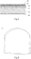
FIG. 3 is a schematic cross-sectional view of a shielding structure according to one embodiment of the present disclosure. -
FIG. 4 is an exploded view of a shielding structure according to one embodiment of the present disclosure. -
FIG. 5 is a perspective view of a safety inspection channel according to one embodiment of the present disclosure. -
FIG. 6 is a side view of a safety inspection channel according to one embodiment of the present disclosure. -
FIG. 7 is a sectional view of part A inFIG. 6 . -
FIG. 8 is an exploded view of a shielding structure according to another embodiment of the present disclosure. - Now, the exemplary implementations will be described more completely with reference to the accompanying drawings. However, the exemplary implementations can be done in various forms and should not be construed as limiting the implementations as set forth herein. Instead, these implementations are provided so that this disclosure will be thorough and complete, and concept of the exemplary implementation will be fully conveyed to those skilled in the art. In the figures, for sake of clarity, thickness of the areas and layers may be exaggerated. Same reference numbers denote the same or similar structures in the figures, and thus the detailed description thereof will be omitted
- Furthermore, the features, structures, or characteristics may be combined in one or more exemplary implementations in any proper manner. Hereinafter, plenty of specific details are set forth in order to facilitate fully understanding the exemplary implementations of the present disclosure. It is aware that those skilled in the art may carry out the technical solutions of the present disclosure even through one or more of the special details are omitted, or by employing other methods, components, and steps, etc. In other instances, the well-known structures, methods, implementations, or operations are not shown or described in detail to avoid obscuring aspects of the present disclosure.
- As shown in
FIGS. 1 and 2, FIG. 1 is a schematic cross-sectional view of a shielding structure in the related arts, andFIG. 2 is a schematic cross-sectional view of a connecting portion of a safety inspection channel in the related arts. - As shown in
FIG. 1 , theshielding structure 1 is composed of twocarbon fiber layers 100 and onerubber coating layer 200, each layer of which has a thickness of about 0.2mm, totally having the thickness of about 0.6mm.This shielding structure is thinner and has less influence on the imaging quality, but for occasions with wider beam surface, the shielding structure has un-satisfied rigidity and poor wear resistance. - And, as shown in
FIG. 2 , theshielding structure 1 has the uniform thickness, when theshielding structure 1 is connected with theadjacent channel structure 2, apressing plate 3 and a supportingplate 4 are respectively arranged on inner and outer surfaces of theshielding structure 1, so that astep 5 is formed between thepressing plate 3 and the surface of theshielding structure 1. Dust or sundries are easily accumulated at thestep 5, and thereby affecting imaging. - The present disclosure provides the
shielding structure 1 of a safety inspection equipment. Theshielding structure 1 and thechannel structure 2 form asafety inspection channel 1000. Specifically, theshielding structure 1 is used for forming a shielding channel 1', and thechannel structures 2 are respectively connected and communicated with both ends of the shielding channel 1', so as to form a through safety inspection channel 1000.Thesafety inspection channel 1000 is mainly used in the safety inspection equipment of luggage. The safety inspection equipment is mainly used in occasions where safety inspection requirements for luggage are required. In the CT imaging system of the safety inspection equipment, the shielding structure has a simple structure, little influence on the imaging quality, light weight, durability and reliability, which are the key elements to affect the equipment imaging system. As shown inFIG. 3 , theshielding structure 1 of the safety inspection equipment of the present disclosure includes a firstcarbon fiber layer 10, apolyurethane layer 20 and a secondcarbon fiber layer 30 sequentially stacked, to form a shielding channel 1' with both ends opened. Since theshielding structure 1 of the present disclosure is used for the safety inspection equipment, theshielding structure 1 is wholly constructed as a channel structure to cooperatively form a safety inspection channel 1000.The secondcarbon fiber layer 30 is an outer layer of the shielding channel 1'. The firstcarbon fiber layer 10 and the secondcarbon fiber layer 30 are made of carbon fiber materials, and thepolyurethane layer 20 is made of polyurethane materials. - In the present disclosure, a polyurethane board layer (i.e., a polyurethane layer) is added between the two carbon fiber layers, since the carbon fiber layer has good strength, the carbon fiber layers are covered on the both sides of the polyurethane board to ensure the overall strength, so that the rigidity of the shielding structure can be improved. And the rigidity of the shielding structure has little influence on the imaging quality, so that the rigidity of the shielding structure can be improved while reducing the influence on the imaging quality. In addition, the polyurethane board layer has small density, so that the polyurethane board layer is lighter than the carbon fiber layer, and thus the total weight can be reduced. And, cost of the polyurethane board layer is low, thus reducing the overall cost.
- And, an outer layer of the shielding channel 1' is a carbon fiber layer, for maintaining the strength of the shielding
structure 1. Thepolyurethane layer 20 is wrapped by the two carbon fiber layers, so that slag and debris of thepolyurethane layer 20 can be avoided. Accordingly, compared with the existing carbon fiber shielding plate structure, the present disclosure can improve the multi-layer carbon fiber shielding plate structure, reduce the influence on the imaging quality, reduce the cost, and can improve the rigidity of the single-layer and double-layer carbon fiber shielding plate structures. - In this embodiment, as shown in
FIG. 3 , the shieldingstructure 1 may further include a thirdcarbon fiber layer 40, which is stacked on one side of the firstcarbon fiber layer 10 away from thepolyurethane layer 20. Wherein, there is one or more third carbon fiber layers 40. By additionally arranging one or more third carbon fiber layers 40 on one side of the firstcarbon fiber layer 10, the strength of the shieldingstructure 1 can be improved, and thus an impact resistance of the shieldingstructure 1 can be improved. The number of the third carbon fiber layers 40 can be determined according to requirement for the strength in different occasions. - For example, in this embodiment, as shown in
FIG. 3 , one thirdcarbon fiber layer 40 is provided. In other embodiments, more than one third carbon fiber layers 40 are provided, and are continuously stacked on one side of the firstcarbon fiber layer 10 away from thepolyurethane layer 20. - In this embodiment, as shown in
FIG. 3 , the shieldingstructure 1 may further include anaramid fiber layer 50, which is stacked on one side of the thirdcarbon fiber layer 40 away from the first carbon fiber layer 10.Thearamid fiber layer 50 has a good abrasion resistance for improving the abrasion resistance of an inner surface of the shieldingstructure 1, and thearamid fiber layer 50 has little influence on CT imaging. - In this embodiment, as shown in
FIG. 3 , the shieldingstructure 1 may further include arubber coating layer 60, which is stacked on one side of thearamid fiber layer 50 away from the third carbon fiber layer 40.The side of therubber coating layer 60 away from thearamid fiber layer 50, which is used as a working surface for the surface of the product, has functions of decoration, weather resistance, crack prevention and the like, and plays a role of protection and decoration for a reinforcing layer, wherein therubber coating layer 60 can be an improved resin. - Each of the first
carbon fiber layer 10, the secondcarbon fiber layer 30 and the thirdcarbon fiber layer 40 has a thickness of 0.2 to 0.4 mm, thepolyurethane layer 20 has a thickness of 3 to 6 mm, and thearamid fiber layer 50 has a thickness of 0.3 to 0.5 mm. - In this embodiment, the thickness of the
rubber coating layer 60 is 0.2mm, the thickness of thearamid fiber layer 50 is 0.3mm, the thicknesses of each of the firstcarbon fiber layer 10, the secondcarbon fiber layer 30 and the thirdcarbon fiber layer 40 is 0.2mm, the thickness of thepolyurethane layer 20 is 5mm, and the total thickness of the shieldingstructure 1, that is, a sum of the thicknesses of the all layers is about 6mm. It should be understood that the thickness range is not limited thereto, and different values of the thickness can be selected according to different layers in different application occasions. - In this embodiment, as shown in
FIG. 4 , the shielding channel 1' is of a three-block structure, which has three joints respectively located at two side walls and a bottom of the shielding channel 1'. And the three-block structure has stable support and high strength. - In another embodiment, as shown in
FIG. 8 , the shielding channel 1' is of a two-half structure, which has two joints respectively located at the top and bottom portions of the shielding channel 1'. And the two-half structure is simple and easy to be assembled. - In this embodiment, as shown in
FIGS. 5-7 , the shielding passage 1' includes a shieldingbody 11 and two extendingportions 12 connected with both opposite ends of the shielding body. Each of the extendingportion 12 is connected with a portion between the outer surface and the inner surface of the shieldingbody 11 on both ends of the shieldingbody 11. The extendingportion 12 extends along an axis x (the axis in this embodiment is an axis x in an extending direction of asafety inspection channel 1000, i.e., the axis x is parallel to a longitudinal direction of thesafety inspection channel 1000 inFIG. 5 ). The thickness of the extendingportion 12 is smaller than the thickness of the shieldingbody 11, and the extendingportion 12 is disposed between the outer surface and the inner surface of the shieldingbody 11. Thesafety inspection channel 1000 further includes apressing plate 3 and a supportingplate 4. Thepressing plate 3 is pressed on the outer surface of the extendingportion 12 and closely adjacent to the shieldingbody 11 and thechannel structure 2. The outer surface of thepressing plate 3 is flush with the outer surfaces of the shieldingbody 11 and thechannel structure 2. The supportingplate 4 is arranged on the inner surfaces of the extendingportion 12 and thechannel structure 2, and is flush with the inner surfaces of the extendingportion 12 and thechannel structure 2. In one embodiment, the extendingportion 12 is formed by extending an edge of the shielding body 11 (the extendingportion 12 is formed continuously along the outer periphery of both ends of the shielding body 11). The extendingportion 12 is structurally different from the shieldingbody 11 in that the structure of the shieldingbody 11 is identical to the structure of theaforesaid shielding structure 1, and the polyurethane layer is not contained in the extendingportion 12. That is to say, the extendingportion 12 is formed by pressing an extending portion of the fiber layer (which may also include a rubber coating layer) of the shieldingbody 11. The extendingportion 12 is configured to reduce the thickness of the edge of the shieldingstructure 1, and furthermore, the extendingportion 12 can be provided between thepressing plate 3 and the supportingplate 4, so that the shieldingstructure 1 can be installed in thesafety inspection channel 1000. As shown inFIG. 7 , by optimizing the shieldingstructure 1, the outer surfaces of the shieldingstructure 1, thepressing plate 3, and thechannel structure 2 are flush, to avoid steps at a junction of thepressing plate 3 and the shieldingstructure 1, and to avoid accumulating dusts or sundries at the steps. - As above described, a polyurethane board layer is added between the two carbon fiber layers in the present disclosure, since the carbon fiber layer has good strength, the carbon fiber layers are covered on the both sides of the polyurethane board to ensure the overall strength, so that the rigidity of the shielding structure can be improved. And the rigidity of the shielding structure has little influence on the imaging quality, so that the rigidity of the shielding structure can be improved while reducing the influence on the imaging quality. In addition, the polyurethane board layer has small density, so that the polyurethane board layer is lighter than the carbon fiber layer, and thus the total weight can be reduced. And, cost of the polyurethane board layer is low, thus reducing the overall cost.
- And, the outer layer of the shielding channel 1' is a carbon fiber layer, for maintaining the strength of the shielding
structure 1. Thepolyurethane layer 20 is wrapped by the two carbon fiber layers 10 and 30, so that the slag and debris of thepolyurethane layer 20 can be avoided. Accordingly, compared with the existing carbon fiber shielding plate structure, the present disclosure can improve the multi-layer carbon fiber shielding plate structure, reduce the influence on the imaging quality, reduce the cost, and can improve the rigidity of the single-layer and double-layer carbon fiber shielding plate structures. - Exemplary embodiments of the present disclosure have been particularly shown and described above. It should be understood that the present disclosure is not limited to the disclosed embodiments. Rather, various modifications and equivalent arrangements within the spirit and scope of the appended claims are intended to be contained.
- Although the present disclosure has been described with reference to a few of typical embodiments, it should be understood that all the terms used are illustrative and exemplary, and nonrestrictive. As the present disclosure may be embodied in a variety of forms without departing from the spirit or scope of the invention, it is to be understood that the above-described embodiments are not limited to any foregoing detail. All changes and modifications within the scope of the claims or their equivalents are intended to be embraced by the appended claims.
Claims (14)
- A shielding structure of a safety inspection equipment, comprising a first carbon fiber layer, a polyurethane layer and a second carbon fiber layer sequentially stacked to be configured as a shielding channel with two opened ends, wherein the second carbon fiber layer is an outer layer of the shielding channel, the first carbon fiber layer and the second carbon fiber layer are made of carbon fiber materials, and the polyurethane layer is made of polyurethane materials.
- The shielding structure of the safety inspection equipment according to claim 1, wherein the shielding structure further comprises a third carbon fiber layer stacked on one side of the first carbon fiber layer away from the polyurethane layer.
- The shielding structure of the safety inspection equipment according to claim 2, wherein number of the third carbon fiber layers is one or more layers.
- The shielding structure of the safety inspection equipment according to claim 2, wherein the third carbon fiber layers are in plural, which are continuously stacked on one side of the first carbon fiber layer away from the polyurethane layer.
- The shielding structure of the safety inspection device according to claim 3, wherein the shielding structure further comprises an aramid fiber layer stacked on one side of the third carbon fiber layer away from the first carbon fiber layer.
- The shielding structure of the safety inspection device according to claim 5, wherein the shielding structure further comprises a rubber coating layer stacked on one side of the aramid fiber layer away from the third carbon fiber layer.
- The shielding structure of safety inspection equipment according to claim 5, wherein a thickness of each of the first carbon fiber layer, the second carbon fiber layer and the third carbon fiber layer is 0.2-0.4mm, a thickness of the polyurethane layer is 3-6mm, and a thickness of the aramid fiber layer is 0.3-0.5 mm.
- The shielding structure of safety inspection equipment according to claim 1, wherein the shielding channel is a three-block structure, having three joints respectively located at two side walls and a bottom portion of the shielding channel.
- The shielding structure of safety inspection equipment according to claim 1, wherein the shielding channel is a two-half structure, having two joints respectively located at a top portion and the bottom portion of the shielding channel.
- The shielding structure of the safety inspection device according to claim 1, wherein the shielding channel comprises a shielding body and an extending portion, the extending portion is connected with a portion between an outer surface and an inner surface of the shielding body on both ends of the shielding body and extends along an axis, and the thickness of the extending portion is smaller than the thickness of the shielding body.
- The shielding structure of the safety inspection device according to claim 1, wherein the shielding channel comprises a shielding body and an extending portion, and the extending portion is formed by extending and pressing fiber layers on both sides of the polyurethane layer of the shielding body.
- A safety inspection channel of a safety inspection equipment, comprising a channel structure and a shielding structure according to any one of claims 1-11, wherein the channel structures are respectively connected and communicated with both ends of the shielding channel, to form a through safety inspection channel.
- The safety inspection channel of the safety inspection device according to claim 1, wherein the shielding channel comprises a shielding body and an extending portion, the extending portion is connected with a portion between the outer surface and the inner surface of the shielding body on both ends of the shielding body and extends along an axis, a thickness of the extending portion is smaller than the thickness of a shielding body; the safety inspection channel further comprises a pressing plate and a supporting plate, the pressing plate is pressed on an outer surface of the extending portion, and closely adjacent to the shielding body and the channel structure; an outer surface of the pressing plate is flush with outer surfaces of the shielding body and the channel structure, and the supporting plate is provided on inner surfaces of the extending portion and the channel structure and flush with inner surfaces of the extending portion and the channel structure.
- The safety inspection channel of the safety inspection equipment according to claim 12, wherein the extending portion is continuously formed along outer peripheries of both ends of the shielding body.
Applications Claiming Priority (2)
| Application Number | Priority Date | Filing Date | Title |
|---|---|---|---|
| CN201810761941.5A CN108614303B (en) | 2018-07-12 | 2018-07-12 | Safety inspection channel |
| PCT/CN2019/089048 WO2020010953A1 (en) | 2018-07-12 | 2019-05-29 | Shielding structure and safety inspection channel of safety inspection device |
Publications (3)
| Publication Number | Publication Date |
|---|---|
| EP3647828A1 true EP3647828A1 (en) | 2020-05-06 |
| EP3647828A4 EP3647828A4 (en) | 2021-04-21 |
| EP3647828B1 EP3647828B1 (en) | 2025-07-09 |
Family
ID=63666384
Family Applications (1)
| Application Number | Title | Priority Date | Filing Date |
|---|---|---|---|
| EP19823761.2A Active EP3647828B1 (en) | 2018-07-12 | 2019-05-29 | Shielding structure and safety inspection channel of safety inspection device |
Country Status (8)
| Country | Link |
|---|---|
| US (1) | US11385377B2 (en) |
| EP (1) | EP3647828B1 (en) |
| JP (1) | JP6976359B2 (en) |
| CN (1) | CN108614303B (en) |
| AU (2) | AU2019299864B2 (en) |
| CA (1) | CA3066392C (en) |
| MY (1) | MY199506A (en) |
| WO (1) | WO2020010953A1 (en) |
Cited By (1)
| Publication number | Priority date | Publication date | Assignee | Title |
|---|---|---|---|---|
| EP4159135A4 (en) * | 2020-05-29 | 2024-07-03 | Tsinghua University | DETECTION PASSAGE, PASSAGE ASSEMBLY AND CT DETECTION DEVICE |
Families Citing this family (2)
| Publication number | Priority date | Publication date | Assignee | Title |
|---|---|---|---|---|
| CN108614303B (en) * | 2018-07-12 | 2024-10-01 | 同方威视技术股份有限公司 | Safety inspection channel |
| CN116773557B (en) * | 2022-12-28 | 2024-02-13 | 清华大学 | Detection channel for CT detection and CT detection device |
Family Cites Families (27)
| Publication number | Priority date | Publication date | Assignee | Title |
|---|---|---|---|---|
| US3737661A (en) * | 1971-03-03 | 1973-06-05 | R Applegate | Portable x-ray radiation shielding device |
| CA985433A (en) * | 1973-07-20 | 1976-03-09 | Melvin L. Foster | High strength low attenuation couch top |
| FR2527920A1 (en) * | 1982-06-04 | 1983-12-09 | Thomson Csf | Composite panels for radiological screens transparent to X=rays - of polyurethane foam between laminated paper covers |
| JPS6082296U (en) * | 1983-11-11 | 1985-06-07 | 石川島播磨重工業株式会社 | radiation shielding sheet |
| JPS62152839A (en) * | 1985-12-27 | 1987-07-07 | 積水化学工業株式会社 | Fiber reinforced resin molded shape and manufacture thereof |
| JPH0651095A (en) * | 1992-07-28 | 1994-02-25 | Sumitomo Metal Ind Ltd | Aromatic material with radiations shelding function |
| US7476889B2 (en) * | 1998-12-07 | 2009-01-13 | Meridian Research And Development | Radiation detectable and protective articles |
| GB0525593D0 (en) * | 2005-12-16 | 2006-01-25 | Cxr Ltd | X-ray tomography inspection systems |
| US7484253B1 (en) * | 2003-05-27 | 2009-02-03 | Qfix Systems, Llc | Patient support element for radiation therapy that reduces skin radiation burn |
| US7991115B2 (en) * | 2007-12-12 | 2011-08-02 | Kabushiki Kaisha Toshiba | Medical image diagnostic device |
| EP2440137A4 (en) * | 2009-06-08 | 2013-01-09 | Oncolog Medical Qa Ab | Table top for radiation therapy |
| DE102009037565A1 (en) * | 2009-08-14 | 2011-02-24 | Mavig Gmbh | Coated microfiber web and method of making the same |
| JP2012093264A (en) * | 2010-10-27 | 2012-05-17 | Nikkiso Co Ltd | Radiation shield cover |
| JP6058883B2 (en) | 2011-11-14 | 2017-01-11 | 恵和株式会社 | Radioactivity protection sheet and method for producing radioactivity protection sheet |
| JP6098086B2 (en) * | 2012-03-28 | 2017-03-22 | 大日本印刷株式会社 | Laminated sheet for carbon fiber reinforced plastic, laminated composite material and method for producing the same |
| CN203015373U (en) * | 2012-11-29 | 2013-06-19 | 成都天奥电子股份有限公司 | A composite layer suitable for the shielding cavity of a microwave circuit |
| CN104325756A (en) | 2013-07-22 | 2015-02-04 | 上海杰事杰新材料(集团)股份有限公司 | Carbon fiber reinforced composite material used for notebook housing and preparation method thereof |
| CN106664816B (en) * | 2014-06-30 | 2020-02-28 | 东丽株式会社 | Laminate and integrated molded article |
| CN204257218U (en) | 2014-10-15 | 2015-04-08 | 扬州锦江有色金属有限公司 | A kind of pipeline nuclear radiation shield bandage |
| KR101633632B1 (en) * | 2015-09-30 | 2016-06-27 | 김동용 | Composite for radiation shielding |
| CN205959627U (en) * | 2016-06-03 | 2017-02-15 | 上海奕瑞光电子科技有限公司 | Carbon fiber product's flat panel detector containing possesses radiation protection ability |
| US20180000432A1 (en) * | 2016-06-29 | 2018-01-04 | Carestream Health, Inc. | Flexible radiopaque apron |
| CN206201589U (en) | 2016-08-23 | 2017-05-31 | 深圳市蓝博威科技有限公司 | A kind of carbon fiber polymer film for processing |
| CN206346423U (en) | 2016-12-19 | 2017-07-21 | 宿迁市金板木业有限公司 | A kind of carbon fiber permanently antistatic thick china |
| CN108001494B (en) * | 2018-01-05 | 2024-09-24 | 同方威视技术股份有限公司 | Luggage cart |
| CN208506272U (en) * | 2018-07-12 | 2019-02-15 | 同方威视技术股份有限公司 | The shielding construction of Security Inspection Equipments and safety inspection channel |
| CN108614303B (en) | 2018-07-12 | 2024-10-01 | 同方威视技术股份有限公司 | Safety inspection channel |
-
2018
- 2018-07-12 CN CN201810761941.5A patent/CN108614303B/en active Active
-
2019
- 2019-05-29 EP EP19823761.2A patent/EP3647828B1/en active Active
- 2019-05-29 MY MYPI2020005754A patent/MY199506A/en unknown
- 2019-05-29 WO PCT/CN2019/089048 patent/WO2020010953A1/en not_active Ceased
- 2019-05-29 US US16/627,426 patent/US11385377B2/en active Active
- 2019-05-29 CA CA3066392A patent/CA3066392C/en active Active
- 2019-05-29 AU AU2019299864A patent/AU2019299864B2/en active Active
- 2019-05-29 JP JP2019568759A patent/JP6976359B2/en active Active
-
2022
- 2022-02-24 AU AU2022201279A patent/AU2022201279B2/en active Active
Cited By (1)
| Publication number | Priority date | Publication date | Assignee | Title |
|---|---|---|---|---|
| EP4159135A4 (en) * | 2020-05-29 | 2024-07-03 | Tsinghua University | DETECTION PASSAGE, PASSAGE ASSEMBLY AND CT DETECTION DEVICE |
Also Published As
| Publication number | Publication date |
|---|---|
| JP2020530100A (en) | 2020-10-15 |
| US11385377B2 (en) | 2022-07-12 |
| AU2019299864A1 (en) | 2020-03-05 |
| CN108614303B (en) | 2024-10-01 |
| CA3066392A1 (en) | 2020-01-12 |
| EP3647828B1 (en) | 2025-07-09 |
| WO2020010953A1 (en) | 2020-01-16 |
| US20210333430A1 (en) | 2021-10-28 |
| CA3066392C (en) | 2022-01-11 |
| MY199506A (en) | 2023-11-02 |
| JP6976359B2 (en) | 2021-12-08 |
| EP3647828A4 (en) | 2021-04-21 |
| AU2022201279A1 (en) | 2022-03-17 |
| AU2022201279B2 (en) | 2023-05-25 |
| CN108614303A (en) | 2018-10-02 |
| AU2019299864B2 (en) | 2021-11-25 |
Similar Documents
| Publication | Publication Date | Title |
|---|---|---|
| AU2022201279B2 (en) | Shielding structure of safety inspection equipment and safety inspection channel | |
| US7040575B2 (en) | Foam composite insulation for aircraft | |
| EP1948503B1 (en) | Integrally damped composite aircraft floor panels | |
| US8317134B2 (en) | Stiffened casing for an aircraft or spacecraft with a laminate stringer of high rigidity and corresponding laminate stringer | |
| US5092618A (en) | Ski comprising damping layers | |
| US20130277372A1 (en) | Carbon-fiber-reinforced plastic structure and fuel tank | |
| CN210479007U (en) | Light wing of small unmanned aerial vehicle | |
| US10259557B2 (en) | Pressure bulkhead for an aircraft fuselage, and an aircraft comprising such a pressure bulkhead | |
| CN117199675A (en) | A battery protective bottom plate, battery pack composite protective structure and vehicle | |
| CN208506272U (en) | The shielding construction of Security Inspection Equipments and safety inspection channel | |
| JP5644329B2 (en) | Honeycomb sandwich structure composite and method for manufacturing honeycomb sandwich structure composite | |
| CN210391133U (en) | A kind of reinforcement board for high-speed rail car ceiling | |
| WO2020253356A1 (en) | Rail vehicle body structure | |
| KR20240098926A (en) | Plate material for battery pack cover | |
| CN110518329B (en) | Exhaust pipe type antenna | |
| KR102521698B1 (en) | Composite material for railway vehicles | |
| CN224117284U (en) | Light sound insulation board of assembled structure | |
| CN219056400U (en) | A PET sandwich composite engine cover structure | |
| US20250158194A1 (en) | Battery pack box and battery pack | |
| CN210890431U (en) | Double-wall glass fiber reinforced plastic-steel composite pipe | |
| KR102240927B1 (en) | Sandwich type CFRP structure inserted with UHSS | |
| CN120879121A (en) | Pallet guard plate structure, battery pallet, battery pack and electric equipment | |
| CN212785806U (en) | Vibrating plate for sound conduction | |
| CN110239661B (en) | A stealth explosion-proof structure | |
| KR101905977B1 (en) | Composite lamination structure, vehicle body panel and partition panel for vehicle |
Legal Events
| Date | Code | Title | Description |
|---|---|---|---|
| STAA | Information on the status of an ep patent application or granted ep patent |
Free format text: STATUS: UNKNOWN |
|
| STAA | Information on the status of an ep patent application or granted ep patent |
Free format text: STATUS: THE INTERNATIONAL PUBLICATION HAS BEEN MADE |
|
| PUAI | Public reference made under article 153(3) epc to a published international application that has entered the european phase |
Free format text: ORIGINAL CODE: 0009012 |
|
| STAA | Information on the status of an ep patent application or granted ep patent |
Free format text: STATUS: REQUEST FOR EXAMINATION WAS MADE |
|
| 17P | Request for examination filed |
Effective date: 20191230 |
|
| AK | Designated contracting states |
Kind code of ref document: A1 Designated state(s): AL AT BE BG CH CY CZ DE DK EE ES FI FR GB GR HR HU IE IS IT LI LT LU LV MC MK MT NL NO PL PT RO RS SE SI SK SM TR |
|
| AX | Request for extension of the european patent |
Extension state: BA ME |
|
| A4 | Supplementary search report drawn up and despatched |
Effective date: 20210323 |
|
| RIC1 | Information provided on ipc code assigned before grant |
Ipc: G01V 5/00 20060101AFI20210317BHEP Ipc: B32B 5/26 20060101ALI20210317BHEP Ipc: B32B 1/08 20060101ALI20210317BHEP Ipc: B32B 3/04 20060101ALI20210317BHEP Ipc: B32B 25/02 20060101ALI20210317BHEP Ipc: B32B 27/12 20060101ALI20210317BHEP Ipc: B32B 27/40 20060101ALI20210317BHEP |
|
| DAV | Request for validation of the european patent (deleted) | ||
| DAX | Request for extension of the european patent (deleted) | ||
| STAA | Information on the status of an ep patent application or granted ep patent |
Free format text: STATUS: EXAMINATION IS IN PROGRESS |
|
| 17Q | First examination report despatched |
Effective date: 20230123 |
|
| GRAP | Despatch of communication of intention to grant a patent |
Free format text: ORIGINAL CODE: EPIDOSNIGR1 |
|
| STAA | Information on the status of an ep patent application or granted ep patent |
Free format text: STATUS: GRANT OF PATENT IS INTENDED |
|
| INTG | Intention to grant announced |
Effective date: 20250130 |
|
| GRAS | Grant fee paid |
Free format text: ORIGINAL CODE: EPIDOSNIGR3 |
|
| GRAA | (expected) grant |
Free format text: ORIGINAL CODE: 0009210 |
|
| STAA | Information on the status of an ep patent application or granted ep patent |
Free format text: STATUS: THE PATENT HAS BEEN GRANTED |
|
| AK | Designated contracting states |
Kind code of ref document: B1 Designated state(s): AL AT BE BG CH CY CZ DE DK EE ES FI FR GB GR HR HU IE IS IT LI LT LU LV MC MK MT NL NO PL PT RO RS SE SI SK SM TR |
|
| REG | Reference to a national code |
Ref country code: GB Ref legal event code: FG4D |
|
| REG | Reference to a national code |
Ref country code: CH Ref legal event code: EP |
|
| REG | Reference to a national code |
Ref country code: IE Ref legal event code: FG4D |
|
| REG | Reference to a national code |
Ref country code: DE Ref legal event code: R096 Ref document number: 602019072376 Country of ref document: DE |
|
| REG | Reference to a national code |
Ref country code: NL Ref legal event code: MP Effective date: 20250709 |
|
| PG25 | Lapsed in a contracting state [announced via postgrant information from national office to epo] |
Ref country code: PT Free format text: LAPSE BECAUSE OF FAILURE TO SUBMIT A TRANSLATION OF THE DESCRIPTION OR TO PAY THE FEE WITHIN THE PRESCRIBED TIME-LIMIT Effective date: 20251110 |
|
| PG25 | Lapsed in a contracting state [announced via postgrant information from national office to epo] |
Ref country code: NL Free format text: LAPSE BECAUSE OF FAILURE TO SUBMIT A TRANSLATION OF THE DESCRIPTION OR TO PAY THE FEE WITHIN THE PRESCRIBED TIME-LIMIT Effective date: 20250709 |
|
| REG | Reference to a national code |
Ref country code: AT Ref legal event code: MK05 Ref document number: 1812326 Country of ref document: AT Kind code of ref document: T Effective date: 20250709 |
|
| PG25 | Lapsed in a contracting state [announced via postgrant information from national office to epo] |
Ref country code: IS Free format text: LAPSE BECAUSE OF FAILURE TO SUBMIT A TRANSLATION OF THE DESCRIPTION OR TO PAY THE FEE WITHIN THE PRESCRIBED TIME-LIMIT Effective date: 20251109 |
|
| PG25 | Lapsed in a contracting state [announced via postgrant information from national office to epo] |
Ref country code: NO Free format text: LAPSE BECAUSE OF FAILURE TO SUBMIT A TRANSLATION OF THE DESCRIPTION OR TO PAY THE FEE WITHIN THE PRESCRIBED TIME-LIMIT Effective date: 20251009 |
|
| REG | Reference to a national code |
Ref country code: LT Ref legal event code: MG9D |
|
| PG25 | Lapsed in a contracting state [announced via postgrant information from national office to epo] |
Ref country code: AT Free format text: LAPSE BECAUSE OF FAILURE TO SUBMIT A TRANSLATION OF THE DESCRIPTION OR TO PAY THE FEE WITHIN THE PRESCRIBED TIME-LIMIT Effective date: 20250709 |
|
| PG25 | Lapsed in a contracting state [announced via postgrant information from national office to epo] |
Ref country code: FI Free format text: LAPSE BECAUSE OF FAILURE TO SUBMIT A TRANSLATION OF THE DESCRIPTION OR TO PAY THE FEE WITHIN THE PRESCRIBED TIME-LIMIT Effective date: 20250709 |
|
| PG25 | Lapsed in a contracting state [announced via postgrant information from national office to epo] |
Ref country code: HR Free format text: LAPSE BECAUSE OF FAILURE TO SUBMIT A TRANSLATION OF THE DESCRIPTION OR TO PAY THE FEE WITHIN THE PRESCRIBED TIME-LIMIT Effective date: 20250709 |
|
| PG25 | Lapsed in a contracting state [announced via postgrant information from national office to epo] |
Ref country code: GR Free format text: LAPSE BECAUSE OF FAILURE TO SUBMIT A TRANSLATION OF THE DESCRIPTION OR TO PAY THE FEE WITHIN THE PRESCRIBED TIME-LIMIT Effective date: 20251010 |
|
| PG25 | Lapsed in a contracting state [announced via postgrant information from national office to epo] |
Ref country code: SE Free format text: LAPSE BECAUSE OF FAILURE TO SUBMIT A TRANSLATION OF THE DESCRIPTION OR TO PAY THE FEE WITHIN THE PRESCRIBED TIME-LIMIT Effective date: 20250709 |
|
| PG25 | Lapsed in a contracting state [announced via postgrant information from national office to epo] |
Ref country code: LV Free format text: LAPSE BECAUSE OF FAILURE TO SUBMIT A TRANSLATION OF THE DESCRIPTION OR TO PAY THE FEE WITHIN THE PRESCRIBED TIME-LIMIT Effective date: 20250709 |
|
| PG25 | Lapsed in a contracting state [announced via postgrant information from national office to epo] |
Ref country code: PL Free format text: LAPSE BECAUSE OF FAILURE TO SUBMIT A TRANSLATION OF THE DESCRIPTION OR TO PAY THE FEE WITHIN THE PRESCRIBED TIME-LIMIT Effective date: 20250709 Ref country code: BG Free format text: LAPSE BECAUSE OF FAILURE TO SUBMIT A TRANSLATION OF THE DESCRIPTION OR TO PAY THE FEE WITHIN THE PRESCRIBED TIME-LIMIT Effective date: 20250709 |
|
| PG25 | Lapsed in a contracting state [announced via postgrant information from national office to epo] |
Ref country code: RS Free format text: LAPSE BECAUSE OF FAILURE TO SUBMIT A TRANSLATION OF THE DESCRIPTION OR TO PAY THE FEE WITHIN THE PRESCRIBED TIME-LIMIT Effective date: 20251009 |
|
| PG25 | Lapsed in a contracting state [announced via postgrant information from national office to epo] |
Ref country code: ES Free format text: LAPSE BECAUSE OF FAILURE TO SUBMIT A TRANSLATION OF THE DESCRIPTION OR TO PAY THE FEE WITHIN THE PRESCRIBED TIME-LIMIT Effective date: 20250709 |
|
| PG25 | Lapsed in a contracting state [announced via postgrant information from national office to epo] |
Ref country code: SM Free format text: LAPSE BECAUSE OF FAILURE TO SUBMIT A TRANSLATION OF THE DESCRIPTION OR TO PAY THE FEE WITHIN THE PRESCRIBED TIME-LIMIT Effective date: 20250709 |
|
| REG | Reference to a national code |
Ref country code: DE Ref legal event code: R097 Ref document number: 602019072376 Country of ref document: DE |
|
| PG25 | Lapsed in a contracting state [announced via postgrant information from national office to epo] |
Ref country code: DK Free format text: LAPSE BECAUSE OF FAILURE TO SUBMIT A TRANSLATION OF THE DESCRIPTION OR TO PAY THE FEE WITHIN THE PRESCRIBED TIME-LIMIT Effective date: 20250709 |
|
| PG25 | Lapsed in a contracting state [announced via postgrant information from national office to epo] |
Ref country code: IT Free format text: LAPSE BECAUSE OF FAILURE TO SUBMIT A TRANSLATION OF THE DESCRIPTION OR TO PAY THE FEE WITHIN THE PRESCRIBED TIME-LIMIT Effective date: 20250709 |
|
| PG25 | Lapsed in a contracting state [announced via postgrant information from national office to epo] |
Ref country code: CZ Free format text: LAPSE BECAUSE OF FAILURE TO SUBMIT A TRANSLATION OF THE DESCRIPTION OR TO PAY THE FEE WITHIN THE PRESCRIBED TIME-LIMIT Effective date: 20250709 |
|
| PG25 | Lapsed in a contracting state [announced via postgrant information from national office to epo] |
Ref country code: EE Free format text: LAPSE BECAUSE OF FAILURE TO SUBMIT A TRANSLATION OF THE DESCRIPTION OR TO PAY THE FEE WITHIN THE PRESCRIBED TIME-LIMIT Effective date: 20250709 Ref country code: SK Free format text: LAPSE BECAUSE OF FAILURE TO SUBMIT A TRANSLATION OF THE DESCRIPTION OR TO PAY THE FEE WITHIN THE PRESCRIBED TIME-LIMIT Effective date: 20250709 |
|
| PLBE | No opposition filed within time limit |
Free format text: ORIGINAL CODE: 0009261 |
|
| STAA | Information on the status of an ep patent application or granted ep patent |
Free format text: STATUS: NO OPPOSITION FILED WITHIN TIME LIMIT |
|
| REG | Reference to a national code |
Ref country code: CH Ref legal event code: L10 Free format text: ST27 STATUS EVENT CODE: U-0-0-L10-L00 (AS PROVIDED BY THE NATIONAL OFFICE) Effective date: 20260521 |
|
| 26N | No opposition filed |
Effective date: 20260410 |
|
| PG25 | Lapsed in a contracting state [announced via postgrant information from national office to epo] |
Ref country code: LT Free format text: LAPSE BECAUSE OF FAILURE TO SUBMIT A TRANSLATION OF THE DESCRIPTION OR TO PAY THE FEE WITHIN THE PRESCRIBED TIME-LIMIT Effective date: 20250709 |