EP3647637A1 - Variable flow controlled diaphragm valve based on shape memory alloy - Google Patents
Variable flow controlled diaphragm valve based on shape memory alloy Download PDFInfo
- Publication number
- EP3647637A1 EP3647637A1 EP19206150.5A EP19206150A EP3647637A1 EP 3647637 A1 EP3647637 A1 EP 3647637A1 EP 19206150 A EP19206150 A EP 19206150A EP 3647637 A1 EP3647637 A1 EP 3647637A1
- Authority
- EP
- European Patent Office
- Prior art keywords
- diaphragm
- wire
- pathway
- valve
- bias
- Prior art date
- Legal status (The legal status is an assumption and is not a legal conclusion. Google has not performed a legal analysis and makes no representation as to the accuracy of the status listed.)
- Granted
Links
Images



Classifications
-
- F—MECHANICAL ENGINEERING; LIGHTING; HEATING; WEAPONS; BLASTING
- F16—ENGINEERING ELEMENTS AND UNITS; GENERAL MEASURES FOR PRODUCING AND MAINTAINING EFFECTIVE FUNCTIONING OF MACHINES OR INSTALLATIONS; THERMAL INSULATION IN GENERAL
- F16K—VALVES; TAPS; COCKS; ACTUATING-FLOATS; DEVICES FOR VENTING OR AERATING
- F16K7/00—Diaphragm valves or cut-off apparatus, e.g. with a member deformed, but not moved bodily, to close the passage ; Pinch valves
- F16K7/12—Diaphragm valves or cut-off apparatus, e.g. with a member deformed, but not moved bodily, to close the passage ; Pinch valves with flat, dished, or bowl-shaped diaphragm
- F16K7/126—Diaphragm valves or cut-off apparatus, e.g. with a member deformed, but not moved bodily, to close the passage ; Pinch valves with flat, dished, or bowl-shaped diaphragm the seat being formed on a rib perpendicular to the fluid line
-
- F—MECHANICAL ENGINEERING; LIGHTING; HEATING; WEAPONS; BLASTING
- F03—MACHINES OR ENGINES FOR LIQUIDS; WIND, SPRING, OR WEIGHT MOTORS; PRODUCING MECHANICAL POWER OR A REACTIVE PROPULSIVE THRUST, NOT OTHERWISE PROVIDED FOR
- F03G—SPRING, WEIGHT, INERTIA OR LIKE MOTORS; MECHANICAL-POWER PRODUCING DEVICES OR MECHANISMS, NOT OTHERWISE PROVIDED FOR OR USING ENERGY SOURCES NOT OTHERWISE PROVIDED FOR
- F03G7/00—Mechanical-power-producing mechanisms, not otherwise provided for or using energy sources not otherwise provided for
- F03G7/06—Mechanical-power-producing mechanisms, not otherwise provided for or using energy sources not otherwise provided for using expansion or contraction of bodies due to heating, cooling, moistening, drying or the like
- F03G7/061—Mechanical-power-producing mechanisms, not otherwise provided for or using energy sources not otherwise provided for using expansion or contraction of bodies due to heating, cooling, moistening, drying or the like characterised by the actuating element
- F03G7/0614—Mechanical-power-producing mechanisms, not otherwise provided for or using energy sources not otherwise provided for using expansion or contraction of bodies due to heating, cooling, moistening, drying or the like characterised by the actuating element using shape memory elements
- F03G7/06143—Wires
-
- F—MECHANICAL ENGINEERING; LIGHTING; HEATING; WEAPONS; BLASTING
- F03—MACHINES OR ENGINES FOR LIQUIDS; WIND, SPRING, OR WEIGHT MOTORS; PRODUCING MECHANICAL POWER OR A REACTIVE PROPULSIVE THRUST, NOT OTHERWISE PROVIDED FOR
- F03G—SPRING, WEIGHT, INERTIA OR LIKE MOTORS; MECHANICAL-POWER PRODUCING DEVICES OR MECHANISMS, NOT OTHERWISE PROVIDED FOR OR USING ENERGY SOURCES NOT OTHERWISE PROVIDED FOR
- F03G7/00—Mechanical-power-producing mechanisms, not otherwise provided for or using energy sources not otherwise provided for
- F03G7/06—Mechanical-power-producing mechanisms, not otherwise provided for or using energy sources not otherwise provided for using expansion or contraction of bodies due to heating, cooling, moistening, drying or the like
- F03G7/064—Mechanical-power-producing mechanisms, not otherwise provided for or using energy sources not otherwise provided for using expansion or contraction of bodies due to heating, cooling, moistening, drying or the like characterised by its use
-
- F—MECHANICAL ENGINEERING; LIGHTING; HEATING; WEAPONS; BLASTING
- F16—ENGINEERING ELEMENTS AND UNITS; GENERAL MEASURES FOR PRODUCING AND MAINTAINING EFFECTIVE FUNCTIONING OF MACHINES OR INSTALLATIONS; THERMAL INSULATION IN GENERAL
- F16K—VALVES; TAPS; COCKS; ACTUATING-FLOATS; DEVICES FOR VENTING OR AERATING
- F16K31/00—Actuating devices; Operating means; Releasing devices
- F16K31/02—Actuating devices; Operating means; Releasing devices electric; magnetic
- F16K31/025—Actuating devices; Operating means; Releasing devices electric; magnetic actuated by thermo-electric means
-
- F—MECHANICAL ENGINEERING; LIGHTING; HEATING; WEAPONS; BLASTING
- F16—ENGINEERING ELEMENTS AND UNITS; GENERAL MEASURES FOR PRODUCING AND MAINTAINING EFFECTIVE FUNCTIONING OF MACHINES OR INSTALLATIONS; THERMAL INSULATION IN GENERAL
- F16K—VALVES; TAPS; COCKS; ACTUATING-FLOATS; DEVICES FOR VENTING OR AERATING
- F16K31/00—Actuating devices; Operating means; Releasing devices
- F16K31/002—Actuating devices; Operating means; Releasing devices actuated by temperature variation
-
- F—MECHANICAL ENGINEERING; LIGHTING; HEATING; WEAPONS; BLASTING
- F16—ENGINEERING ELEMENTS AND UNITS; GENERAL MEASURES FOR PRODUCING AND MAINTAINING EFFECTIVE FUNCTIONING OF MACHINES OR INSTALLATIONS; THERMAL INSULATION IN GENERAL
- F16K—VALVES; TAPS; COCKS; ACTUATING-FLOATS; DEVICES FOR VENTING OR AERATING
- F16K7/00—Diaphragm valves or cut-off apparatus, e.g. with a member deformed, but not moved bodily, to close the passage ; Pinch valves
- F16K7/12—Diaphragm valves or cut-off apparatus, e.g. with a member deformed, but not moved bodily, to close the passage ; Pinch valves with flat, dished, or bowl-shaped diaphragm
Definitions
- circuitry is operably coupled to the wire and configured to cause the wire to be in one of the unheated and the unheated states.
- the circuitry is partially supported in the first body.
- the circuitry includes a switch configured to assume open or closed conditions such that the wire is caused to be in the unheated or the heated states, respectively.
Landscapes
- Engineering & Computer Science (AREA)
- General Engineering & Computer Science (AREA)
- Mechanical Engineering (AREA)
- Chemical & Material Sciences (AREA)
- Combustion & Propulsion (AREA)
- Temperature-Responsive Valves (AREA)
- Indication Of The Valve Opening Or Closing Status (AREA)
Abstract
Description
- This application claims the benefit of Indian Patent Application No.
201811040936, filed October 30, 2018 - The following description relates to valves and, more particularly, to a variable flow control diaphragm valve that is operated based on a response of a shape memory alloy.
- Variable flow valves are commonly used in multiple technologies and applications. They are often reliant upon the operation of a solenoid element, which is activated or deactivated in order to move a diaphragm between open and closed positions.
- It has been found, however, that variable flow valves that rely upon solenoid elements exhibit operational drawbacks. These include, but are not limited to, the fact that solenoids require complex electronics and can be negatively affected by electro-magnetic fields or interference and are also susceptible to dust and moisture infiltration that can degrade performance.
- According to one aspect of the disclosure, a valve is provided and includes a valve body defining a pathway, a diaphragm and a wire. The diaphragm is configured to assume first or second conditions in which the diaphragm blocks or permits fluid flow through the pathway, respectively. The diaphragm is biased toward assumption of the first condition. The wire is coupled to the diaphragm. The wire has an uncontracted length in an unheated state whereby the wire permits assumption of the first condition by the diaphragm due to the bias and a contracted length in a heated state whereby the wire pulls the diaphragm toward assumption of the second condition in opposition to the bias.
- In accordance with additional or alternative embodiments, the valve body defines the pathway and an aperture open to the pathway, the diaphragm is coupled to the valve body at the aperture and the pathway includes a curved inlet portion, a curved outlet portion and a central portion traversable by the diaphragm in which the curved inlet and outlet portions meet.
- In accordance with additional or alternative embodiments, an elastic element is configured to apply the bias to the diaphragm or the diaphragm has an elastic characteristic from which the bias arises.
- In accordance with additional or alternative embodiments, the wire includes shape memory alloy.
- In accordance with additional or alternative embodiments, a difference between the uncontracted and contracted lengths is about 3-4% of the uncontracted length.
- In accordance with additional or alternative embodiments, circuitry is operably coupled to the wire and configured to cause the wire to be in one of the unheated and the unheated states.
- In accordance with additional or alternative embodiments, the circuitry includes a switch configured to assume open or closed conditions such that the wire is caused to be in the unheated or the heated states, respectively.
- In accordance with additional or alternative embodiments, the circuitry includes first and second pulse width modulation (PWM) signals in series.
- In accordance with another aspect of the disclosure, a valve is provided and includes a first body, a second body defining a pathway and an aperture, a diaphragm and a wire. The diaphragm is coupled to the second body at the aperture and is configured to assume first or second conditions in which the diaphragm blocks or permits fluid flow through the pathway, respectively. The diaphragm is biased toward assumption of the first condition. The wire is coupled to the first body and the diaphragm. The wire includes shape memory alloy and has an uncontracted length in an unheated state whereby the wire permits assumption of the first condition by the diaphragm due to the bias and a contracted length in a heated state whereby the wire pulls the diaphragm toward assumption of the second condition in opposition to the bias.
- In accordance with additional or alternative embodiments, pulleys are disposed within the first body and the wire extends about the pulleys.
- In accordance with additional or alternative embodiments, the pulleys are arranged in a staggered formation.
- In accordance with additional or alternative embodiments, the second body defines the aperture to be open to the pathway, the diaphragm is coupled to the valve body at the aperture and the pathway includes a curved inlet portion, a curved outlet portion and a central portion traversable by the diaphragm in which the curved inlet and outlet portions meet.
- In accordance with additional or alternative embodiments, an elastic element is configured to apply the bias to the diaphragm or the diaphragm has an elastic characteristic from which the bias arises.
- In accordance with additional or alternative embodiments, the wire comprises shape memory alloy.
- In accordance with additional or alternative embodiments, a difference between the uncontracted and contracted lengths is about 3-4% of the uncontracted length.
- In accordance with additional or alternative embodiments, circuitry is operably coupled to the wire and configured to cause the wire to be in one of the unheated and the unheated states.
- In accordance with additional or alternative embodiments, the circuitry is partially supported in the first body.
- In accordance with additional or alternative embodiments, the circuitry includes a switch configured to assume open or closed conditions such that the wire is caused to be in the unheated or the heated states, respectively.
- In accordance with additional or alternative embodiments, the circuitry includes first and second pulse width modulation (PWM) signals in series.
- According to yet another aspect of the disclosure, a method of operating a valve in which a diaphragm blocks or permits fluid flow through a pathway, the diaphragm is biased toward permitting the fluid flow and a shape memory alloy wire is coupled to the diaphragm and has an uncontracted length in an unheated state whereby the wire permits the diaphragm to permit the fluid flow due to the bias and a contracted length in a heated state whereby the wire pulls the diaphragm toward blocking the fluid flow in opposition to the bias is provided. The method includes generating a first signal which causes the wire to be placed in the unheated state and generating a second signal which causes the wire to be placed in the heated state.
- These and other advantages and features will become more apparent from the following description taken in conjunction with the drawings.
- The subject matter, which is regarded as the disclosure, is particularly pointed out and distinctly claimed in the claims at the conclusion of the specification. The foregoing and other features, and advantages of the disclosure are apparent from the following detailed description taken in conjunction with the accompanying drawings in which:
-
FIG. 1 is an exploded front view of a valve in accordance with embodiments; -
FIG. 2 is an exploded side view of the valve ofFIG. 1 ; -
FIG. 3 is a front view of a portion of the valve ofFIGS. 1 and2 in a closed state; -
FIG. 4 is a front view of the portion of the valve in an open state; -
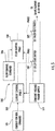
FIG. 5 is a schematic diagram illustrating circuitry to control the valve ofFIGS. 1-4 in accordance with embodiments; -
FIG. 6 is a graphical illustration of pulse width modulation (PWM) signals of the circuitry ofFIG. 5 ; and -
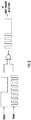
FIG. 7 is a graphical illustration of cycling of the circuitry ofFIG. 5 . - These and other advantages and features will become more apparent from the following description taken in conjunction with the drawings.
- As will be described below, a variable flow control valve is provided and employs shape memory alloy to control operations of a diaphragm.
- With reference to
FIGS. 1-4 , avalve 101 is provided. Thevalve 101 includes a wire housing orfirst body 110 and a valve orsecond body 120. - The
first body 110 includessidewalls 111 that are formed to define a generallyempty interior 112 with anopening 113 and includespulleys 114. Thepulleys 114 can be distributed throughout theinterior 112 and can be independently rotatable. In accordance with embodiments, thepulleys 114 can be disposed in a staggeredformation 115. Of thepulleys 114, afirst pulley 1141 can be provided as aterminal block 116 and afinal pulley 114n can be provided proximate to the opening 113. - The
second body 120 is formed to define apathway 130 and anaperture 140, which is open to thepathway 130. Thepathway 130 has aninlet portion 131 that curvi-linearly extends into and through an interior of thesecond body 120 from afirst side 121 thereof, anoutlet portion 132 that curvi-linearly extends through thesecond body 120 and to asecond side 122 thereof and acentral portion 133 at which theinlet portion 131 and theoutlet portion 132 meet. Thecentral portion 133 extends through a sidewall of thesecond body 120 to form theaperture 140 such that theaperture 140 extends across a substantial length of thecentral portion 133. - The
valve 101 further includes adiaphragm 150 that can be coupled to thesecond body 120. Thediaphragm 150 includes adiaphragm section 151 and aplate section 152 surrounding thediaphragm section 151. Theplate section 152 can be secured to the sidewall of thesecond body 120 by aplate element 153 andfasteners 154, which are extendable through theplate element 153 and into thesecond body 120, such that thediaphragm section 151 is positioned at theaperture 140. Thediaphragm section 151 is sized to extend along and to traverse theaperture 140. In addition, thediaphragm section 151 is flexible and configured to assume a first condition or a second condition. - As shown in
FIG. 3 , when thediaphragm section 151 assumes the first condition, thediaphragm section 151 abuts with the inner and outer sidewalls of theinlet portion 131 and with the inner and outer sidewalls of theoutlet portion 132 to thus block fluid flow through thepathway 130. - As shown in
FIG. 4 , when thediaphragm section 151 assumes the second condition, thediaphragm section 151 is displaced from inner sidewalls of theinlet portion 131 and from inner sidewalls of theoutlet section 132 to thus permit fluid flow through thepathway 130. - A bias can be applied to the
diaphragm section 151 to urge thediaphragm section 151 to normally assume the first condition. This bias can be applied to thediaphragm section 151 by anelastic element 155, such as a compression spring, which is interposed between thediaphragm section 151 and theplate element 153. The bias can also arise from a springiness characteristic of thediaphragm section 151 itself. - The
valve 101 also includes awire 160. Thewire 160 is coupled at a first end thereof to thefirst pulley 1141 in thefirst body 110 and at a second end thereof to ahook 156 extending from thediaphragm section 151. Thewire 160 is also routed to extend around each of the pulleys 114 (in, e.g., a serpentine pathway with thepulleys 114 in the staggered formation 115) including thefinal pulley 114n prior to extending out of thefirst body 110 through theopening 110. Thewire 160 includes shape memory alloy that contracts when thewire 160 is heated and extends when thewire 160 is cooled. As such, thewire 160 has an uncontracted length L1 (seeFIG. 3 ) when thewire 160 is in an unheated state and a contracted length L2 (seeFIG. 4 ) when thewire 160 is in a heated state. When thewire 160 is in the unheated state and has the uncontracted length L1, thewire 160 permits thediaphragm section 151 to assume the first condition due to the bias applied to thediaphragm section 151. Therefore, the provision of thewire 160 in the unheated stated effectively causes thediaphragm section 151 to block fluid flow through thepathway 130. When thewire 160 is in the heated state and the contracted length L2, thewire 160 exerts a pulling force on thediaphragm section 151 and thus pulls thediaphragm section 151 toward assumption of the second condition in opposition to the bias applied to thediaphragm section 151. Therefore, the provision of thewire 160 in the heated state effectively causes thediaphragm section 151 to permit the fluid flow through thepathway 130. - The shape memory alloy of the
wire 160 can include one or more of nickel and titanium (NITI) alloys, copper-zinc-aluminum (CuZnAL) alloys, copper-aluminum-nickel (CuAINi) alloys and iron-based alloys. These and other similar shape memory alloy materials characteristically offer high work performance and provide noise-free and vibration-free motions. They also do not exhibit susceptibility to electromagnetic fields while they do exhibit corrosion resistance and offer resistance against dust or moisture. - The shape memory alloy of the
wire 160 is selected such that a difference between the uncontracted length L1 and the contracted length L2 is about 3-4% of the uncontracted length L1. This being the case, the routing of thewire 160 about each of thepulleys 114 allows for a total length of thewire 160 to be increased regardless of whether thewire 160 is in the unheated or heated state. That is, the routing of thewire 160 about each of thepulleys 114 allows the uncontracted length L1 of thewire 160 to be increased and in turn provides for an increased differential between the uncontracted length L1 and the contracted length L2. This leads to a more controllable operation of thediaphragm section 151 by the contraction of thewire 160. - With continued reference to
FIG. 1 and with additional reference toFIGS. 5-7 , thevalve 101 includescircuitry 170. Thecircuitry 170 is at least partially supported in thefirst body 110, is operably coupled to thewire 160 and is configured to cause thewire 160 to be in one of the unheated and the unheated states. Thecircuitry 170 includes a firstterminal block 171, which may be electrically coupled with thefirst pulley 1141 and thewire 160, a secondterminal block 172, wiring 173 extending between the first and second terminal blocks 171 and 172 and a conductor 174, which extends from the secondterminal block 172 to thewire 160. Thecircuitry 170 further includes aresistive element 175, which limits current that can be carried along thewiring 173, aswitch element 176 and avoltage source 177. Theswitch element 176 and thevoltage source 177 are both disposed along thewiring 173 with thevoltage source 177 disposed in series between theresistive element 175 and theswitch element 176. Theswitch element 176 is configured to assume open or closed conditions. In the open condition, theswitch element 176 prevents current from being applied to thewire 160 whereupon thewire 160 is caused to be in the unheated state. In the closed condition, theswitch element 176 allows current to be applied to thewire 160 whereupon the current heats thewire 160 and thewire 160 is caused to be in the heated state. - Control of the
switch element 176 can be provided bycontrol elements 180, as shown inFIG. 5 , with theswitch element 176 including or being provided asfirst switch 181 andsecond switch 182 in series. The control elements include thevoltage source 177, which supplies a constant voltage power supply signal to acurrent control unit 183 and aflow control unit 184. Thecurrent control unit 183 is receptive of this constant voltage power supply signal and a current control command signal from a potentiometer of a currentcontrol command unit 185 and is configured to generate a first pulse width modulation signal (PWM), PWM1, accordingly. Theflow control unit 184 is receptive of the constant voltage power supply signal and a flow control command signal from a potentiometer of a flowcontrol command unit 186 and is configured to generate a second PWM, PWM2, accordingly. The first and second PWMs, PWM1 andPWM 2, are employed to control the first andsecond switches - As shown in
FIG. 6 , with the first and second PWMs, PWM1 andPWM 2, employed to control the first andsecond switches control elements 180 effectively form an AND gate in which both of the first andsecond switches wire 160. - In accordance with embodiments, the first PWM, PWM1, can be preset and can cycle on an order of 100s of micro seconds or shorter whereas the second PWM, PWM2, can be user defined and can cycle on the order of seconds.
- As shown in
FIG. 7 , thevalve 101 can be controlled to have differing flow conditions in different cycles. For example, the first and second PWMS, PWM1 and PWM2, can be generated such that thevalve 101 is open for 25% of a given time incycle 1, the first and second PWMS, PWM1 and PWM2, can be generated such that thevalve 101 is open for 50% of a given time incycle 2, the first and second PWMS, PWM1 and PWM2, can be generated such that thevalve 101 is open for 75% of a given time incycle 3, the first and second PWMS, PWM1 and PWM2, can be generated such that thevalve 101 is closed for 100% of a given time incycle 4 and the first and second PWMS, PWM1 and PWM2, can be generated such that thevalve 101 is open for 100% of a given time in cycle 5. - Technical effects and benefits of the features described herein are the provision of a lightweight and quiet valve that is simple to use, easy to manufacture and applicable in many cases where there is a need for variable flow. For example, the valve can be used in fuel inerting systems in aircraft, to control hydraulic or pneumatic actuators in aircraft and in implantable/non-implantable medical applications. The valve does not require complex electronics, electro-magnetic interference (EMI) issues are reduced as compared to solenoid valves and dust or contaminations will not affects its operation.
- While the disclosure is provided in detail in connection with only a limited number of embodiments, it should be readily understood that the disclosure is not limited to such disclosed embodiments. Rather, the disclosure can be modified to incorporate any number of variations, alterations, substitutions or equivalent arrangements not heretofore described, but which are commensurate with the scope of the invention as defined by the claims. Additionally, while various embodiments of the disclosure have been described, it is to be understood that the exemplary embodiment(s) may include only some of the described exemplary aspects. Accordingly, the disclosure is not to be seen as limited by the foregoing description, but is only limited by the scope of the appended claims.
Claims (14)
- A valve, comprising:a valve body (110, 120) defining a pathway (130);a diaphragm (150) configured to assume first or second conditions in which the diaphragm blocks or permits fluid flow through the pathway, respectively, the diaphragm being biased toward assumption of the first condition; anda wire (160) coupled to the diaphragm and having an uncontracted length in an unheated state whereby the wire permits assumption of the first condition by the diaphragm due to the bias and a contracted length in a heated state whereby the wire pulls the diaphragm toward assumption of the second condition in opposition to the bias.
- The valve according to claim 1, wherein:the valve body defines the pathway and an aperture (140) open to the pathway,the diaphragm is coupled to the valve body at the aperture, andthe pathway comprises a curved inlet portion (131), a curved outlet portion (132) and a central portion traversable by the diaphragm in which the curved inlet and outlet portions meet.
- The valve according to claim 1 or 2, wherein the wire (160) comprises shape memory alloy.
- A valve, comprising:a first body (110);a second body (120) defining a pathway (130) and an aperture (140);a diaphragm (150) coupled to the second body at the aperture and configured to assume first or second conditions in which the diaphragm blocks or permits fluid flow through the pathway, respectively, the diaphragm being biased toward assumption of the first condition; anda wire (160) coupled to the first body and the diaphragm,the wire comprising shape memory alloy and having an uncontracted length in an unheated state whereby the wire permits assumption of the first condition by the diaphragm due to the bias and a contracted length in a heated state whereby the wire pulls the diaphragm toward assumption of the second condition in opposition to the bias.
- The valve according to claim 4, further comprising pulleys (114) disposed within the first body and about which the wire extends.
- The valve according to claim 5, wherein the pulleys are arranged in a staggered formation.
- The valve according to claim 4, 5 or 6, wherein:the second body (120) defines the aperture to be open to the pathway,the diaphragm (150) is coupled to the valve body at the aperture, andthe pathway (130) comprises a curved inlet portion, a curved outlet portion and a central portion traversable by the diaphragm in which the curved inlet and outlet portions meet.
- The valve according to any preceding claim, wherein:an elastic element (155) is configured to apply the bias to the diaphragm, orthe diaphragm has an elastic characteristic from which the bias arises.
- The valve according to any preceding claim, wherein a difference between the uncontracted and contracted lengths is about 3-4% of the uncontracted length.
- The valve according to any preceding claim, further comprising circuitry (170) operably coupled to the wire and configured to cause the wire to be in one of the unheated and the heated states.
- The valve according to claim 10 when dependent on claim 4, wherein the circuitry is partially supported in the first body.
- The valve according to claim 10, wherein the circuitry comprises a switch (176) configured to assume open or closed conditions such that the wire is caused to be in the unheated or the heated states, respectively.
- The valve according to claim 10, wherein the circuitry comprises first and second pulse width modulation, PWM, signals in series.
- A method of operating a valve in which:a diaphragm blocks or permits fluid flow through a pathway,the diaphragm is biased toward permitting the fluid flow, anda shape memory alloy wire is coupled to the diaphragm and has an uncontracted length in an unheated state whereby the wire permits the diaphragm to permit the fluid flow due to the bias and a contracted length in a heated state whereby the wire pulls the diaphragm toward blocking the fluid flow in opposition to the bias,the method comprising:generating a first signal which causes the wire to be placed in the unheated state; andgenerating a second signal which causes the wire to be placed in the heated state.
Applications Claiming Priority (1)
| Application Number | Priority Date | Filing Date | Title |
|---|---|---|---|
| IN201811040936 | 2018-10-30 |
Publications (2)
| Publication Number | Publication Date |
|---|---|
| EP3647637A1 true EP3647637A1 (en) | 2020-05-06 |
| EP3647637B1 EP3647637B1 (en) | 2022-06-15 |
Family
ID=68392884
Family Applications (1)
| Application Number | Title | Priority Date | Filing Date |
|---|---|---|---|
| EP19206150.5A Active EP3647637B1 (en) | 2018-10-30 | 2019-10-30 | Variable flow controlled diaphragm valve based on shape memory alloy |
Country Status (2)
| Country | Link |
|---|---|
| US (1) | US10982783B2 (en) |
| EP (1) | EP3647637B1 (en) |
Cited By (1)
| Publication number | Priority date | Publication date | Assignee | Title |
|---|---|---|---|---|
| GB2613329A (en) * | 2021-08-18 | 2023-06-07 | Oxford Gas Products Ltd | Valve Actuation Systems |
Families Citing this family (2)
| Publication number | Priority date | Publication date | Assignee | Title |
|---|---|---|---|---|
| US12384515B2 (en) | 2023-09-08 | 2025-08-12 | Hamilton Sundstrand Corporation | Airfoil formed of thermally adaptive materials and a thermoelectric junction |
| US12162606B1 (en) | 2023-09-08 | 2024-12-10 | Hamilton Sundstrand Corporation | Metal plated plastic ACM part with internal thermally adaptive structure |
Citations (6)
| Publication number | Priority date | Publication date | Assignee | Title |
|---|---|---|---|---|
| US6279869B1 (en) * | 1999-11-23 | 2001-08-28 | Tadeusz Olewicz | Proportional flow control valve |
| US20030116737A1 (en) * | 2000-05-24 | 2003-06-26 | Jang Kil Yong | Water saving automatic valve |
| JP2006125445A (en) * | 2004-10-26 | 2006-05-18 | Takasago Electric Inc | Direction selector valve |
| JP2007078028A (en) * | 2005-09-12 | 2007-03-29 | Star Micronics Co Ltd | Valve device |
| US20100108922A1 (en) * | 2008-08-14 | 2010-05-06 | Leonid Foshansky | Multi-stable actuation apparatus and methods for making and using the same |
| US20120153043A1 (en) * | 2010-12-15 | 2012-06-21 | Chaitanya Arekar | Power-efficient actuator assemblies and methods of manufacture |
Family Cites Families (13)
| Publication number | Priority date | Publication date | Assignee | Title |
|---|---|---|---|---|
| US1070027A (en) * | 1912-08-03 | 1913-08-12 | Warren Webster & Co | Multiple-cell thermostat. |
| US2960303A (en) * | 1955-04-22 | 1960-11-15 | Cosby D P Smallpeice | Fluid control valve |
| US3215396A (en) * | 1962-07-27 | 1965-11-02 | King Seeley Thermos Co | Hot wire gas valve |
| DE2717467C3 (en) * | 1977-04-20 | 1980-09-25 | Danfoss A/S, Nordborg (Daenemark) | Servomotor operated with heatable expansion material |
| US4846215A (en) * | 1988-06-07 | 1989-07-11 | Marathon Oil Company | Back pressure regulator |
| US4973024A (en) * | 1989-09-26 | 1990-11-27 | Toki Corporation Kabushiki Kaisha | Valve driven by shape memory alloy |
| US5325880A (en) | 1993-04-19 | 1994-07-05 | Tini Alloy Company | Shape memory alloy film actuated microvalve |
| CA2286277C (en) | 1998-10-16 | 2007-07-24 | Haworth, Inc. | Keyboard pad with reversible mouse pad |
| US6247678B1 (en) | 1999-11-01 | 2001-06-19 | Swagelok Company | Shape memory alloy actuated fluid control valve |
| US7862000B2 (en) * | 2006-02-03 | 2011-01-04 | California Institute Of Technology | Microfluidic method and structure with an elastomeric gas-permeable gasket |
| US7971651B2 (en) | 2007-11-02 | 2011-07-05 | Chevron U.S.A. Inc. | Shape memory alloy actuation |
| PL221673B1 (en) * | 2011-12-20 | 2016-05-31 | Bitron Poland Spółka Z Ograniczoną Odpowiedzialnością | Electrically controlled actuating device and the dispensing device |
| JP2019011804A (en) * | 2017-06-29 | 2019-01-24 | 高砂電気工業株式会社 | Shape memory alloy valve device |
-
2019
- 2019-03-13 US US16/352,603 patent/US10982783B2/en active Active
- 2019-10-30 EP EP19206150.5A patent/EP3647637B1/en active Active
Patent Citations (6)
| Publication number | Priority date | Publication date | Assignee | Title |
|---|---|---|---|---|
| US6279869B1 (en) * | 1999-11-23 | 2001-08-28 | Tadeusz Olewicz | Proportional flow control valve |
| US20030116737A1 (en) * | 2000-05-24 | 2003-06-26 | Jang Kil Yong | Water saving automatic valve |
| JP2006125445A (en) * | 2004-10-26 | 2006-05-18 | Takasago Electric Inc | Direction selector valve |
| JP2007078028A (en) * | 2005-09-12 | 2007-03-29 | Star Micronics Co Ltd | Valve device |
| US20100108922A1 (en) * | 2008-08-14 | 2010-05-06 | Leonid Foshansky | Multi-stable actuation apparatus and methods for making and using the same |
| US20120153043A1 (en) * | 2010-12-15 | 2012-06-21 | Chaitanya Arekar | Power-efficient actuator assemblies and methods of manufacture |
Cited By (2)
| Publication number | Priority date | Publication date | Assignee | Title |
|---|---|---|---|---|
| GB2613329A (en) * | 2021-08-18 | 2023-06-07 | Oxford Gas Products Ltd | Valve Actuation Systems |
| GB2613329B (en) * | 2021-08-18 | 2024-08-14 | Oxford Gas Products Ltd | Valve Actuation Systems |
Also Published As
| Publication number | Publication date |
|---|---|
| US10982783B2 (en) | 2021-04-20 |
| US20200132208A1 (en) | 2020-04-30 |
| EP3647637B1 (en) | 2022-06-15 |
Similar Documents
| Publication | Publication Date | Title |
|---|---|---|
| EP3647637B1 (en) | Variable flow controlled diaphragm valve based on shape memory alloy | |
| US6840257B2 (en) | Proportional valve with shape memory alloy actuator | |
| US6374608B1 (en) | Shape memory alloy wire actuator | |
| EP1014395B1 (en) | Method and apparatus for reducing the noise of electromagnetically operated devices | |
| US5996964A (en) | Magnetic flow controller | |
| DE102013010027A1 (en) | Drive device and method for controlling the drive means for generating an actuating movement | |
| CN103174862A (en) | Shape memory alloy actuator | |
| US11187345B2 (en) | Paraffin actuated diaphragm valve | |
| JP2004308909A (en) | Hydraulic poppet valve with force feedback | |
| DE102011117125A1 (en) | switch panel | |
| EP3366204B1 (en) | Automated non-magnetic medical monitor using shape memory actuators | |
| US20120153043A1 (en) | Power-efficient actuator assemblies and methods of manufacture | |
| DE3221928A1 (en) | ELECTROPNEUMATIC PRE-CONTROL STAGE FOR A PNEUMATIC SERVO VALVE | |
| US8220259B1 (en) | Shape-memory alloy actuator | |
| JP2008508485A (en) | Microvalve actuator control method | |
| CN110580997B (en) | Pulse Width Modulation Control of Solenoid Valve | |
| EP2212494B1 (en) | Solenoid controller for electromechanical lock | |
| US20150377378A1 (en) | A magnetic valve with an armature arranged inside a piston | |
| DE102013225530A1 (en) | Household appliance with a solenoid valve | |
| CN107076312B (en) | Valve assembly with electronic control | |
| EP3152471B1 (en) | Solenoid valve | |
| DE102017106158B4 (en) | Thermostat with hybrid actuator | |
| EP1379782B1 (en) | Actuator comprising a shape memory material | |
| US9976670B2 (en) | Gas cock | |
| JPS63246580A (en) | Valve |
Legal Events
| Date | Code | Title | Description |
|---|---|---|---|
| PUAI | Public reference made under article 153(3) epc to a published international application that has entered the european phase |
Free format text: ORIGINAL CODE: 0009012 |
|
| STAA | Information on the status of an ep patent application or granted ep patent |
Free format text: STATUS: THE APPLICATION HAS BEEN PUBLISHED |
|
| AK | Designated contracting states |
Kind code of ref document: A1 Designated state(s): AL AT BE BG CH CY CZ DE DK EE ES FI FR GB GR HR HU IE IS IT LI LT LU LV MC MK MT NL NO PL PT RO RS SE SI SK SM TR |
|
| AX | Request for extension of the european patent |
Extension state: BA ME |
|
| STAA | Information on the status of an ep patent application or granted ep patent |
Free format text: STATUS: REQUEST FOR EXAMINATION WAS MADE |
|
| 17P | Request for examination filed |
Effective date: 20201106 |
|
| RBV | Designated contracting states (corrected) |
Designated state(s): AL AT BE BG CH CY CZ DE DK EE ES FI FR GB GR HR HU IE IS IT LI LT LU LV MC MK MT NL NO PL PT RO RS SE SI SK SM TR |
|
| STAA | Information on the status of an ep patent application or granted ep patent |
Free format text: STATUS: EXAMINATION IS IN PROGRESS |
|
| 17Q | First examination report despatched |
Effective date: 20210212 |
|
| GRAP | Despatch of communication of intention to grant a patent |
Free format text: ORIGINAL CODE: EPIDOSNIGR1 |
|
| STAA | Information on the status of an ep patent application or granted ep patent |
Free format text: STATUS: GRANT OF PATENT IS INTENDED |
|
| INTG | Intention to grant announced |
Effective date: 20220127 |
|
| GRAS | Grant fee paid |
Free format text: ORIGINAL CODE: EPIDOSNIGR3 |
|
| GRAA | (expected) grant |
Free format text: ORIGINAL CODE: 0009210 |
|
| STAA | Information on the status of an ep patent application or granted ep patent |
Free format text: STATUS: THE PATENT HAS BEEN GRANTED |
|
| AK | Designated contracting states |
Kind code of ref document: B1 Designated state(s): AL AT BE BG CH CY CZ DE DK EE ES FI FR GB GR HR HU IE IS IT LI LT LU LV MC MK MT NL NO PL PT RO RS SE SI SK SM TR |
|
| REG | Reference to a national code |
Ref country code: CH Ref legal event code: EP Ref country code: GB Ref legal event code: FG4D |
|
| REG | Reference to a national code |
Ref country code: IE Ref legal event code: FG4D |
|
| REG | Reference to a national code |
Ref country code: DE Ref legal event code: R096 Ref document number: 602019015854 Country of ref document: DE |
|
| REG | Reference to a national code |
Ref country code: AT Ref legal event code: REF Ref document number: 1498578 Country of ref document: AT Kind code of ref document: T Effective date: 20220715 |
|
| REG | Reference to a national code |
Ref country code: LT Ref legal event code: MG9D |
|
| REG | Reference to a national code |
Ref country code: NL Ref legal event code: MP Effective date: 20220615 |
|
| PG25 | Lapsed in a contracting state [announced via postgrant information from national office to epo] |
Ref country code: SE Free format text: LAPSE BECAUSE OF FAILURE TO SUBMIT A TRANSLATION OF THE DESCRIPTION OR TO PAY THE FEE WITHIN THE PRESCRIBED TIME-LIMIT Effective date: 20220615 Ref country code: NO Free format text: LAPSE BECAUSE OF FAILURE TO SUBMIT A TRANSLATION OF THE DESCRIPTION OR TO PAY THE FEE WITHIN THE PRESCRIBED TIME-LIMIT Effective date: 20220915 Ref country code: LT Free format text: LAPSE BECAUSE OF FAILURE TO SUBMIT A TRANSLATION OF THE DESCRIPTION OR TO PAY THE FEE WITHIN THE PRESCRIBED TIME-LIMIT Effective date: 20220615 Ref country code: HR Free format text: LAPSE BECAUSE OF FAILURE TO SUBMIT A TRANSLATION OF THE DESCRIPTION OR TO PAY THE FEE WITHIN THE PRESCRIBED TIME-LIMIT Effective date: 20220615 Ref country code: GR Free format text: LAPSE BECAUSE OF FAILURE TO SUBMIT A TRANSLATION OF THE DESCRIPTION OR TO PAY THE FEE WITHIN THE PRESCRIBED TIME-LIMIT Effective date: 20220916 Ref country code: FI Free format text: LAPSE BECAUSE OF FAILURE TO SUBMIT A TRANSLATION OF THE DESCRIPTION OR TO PAY THE FEE WITHIN THE PRESCRIBED TIME-LIMIT Effective date: 20220615 Ref country code: BG Free format text: LAPSE BECAUSE OF FAILURE TO SUBMIT A TRANSLATION OF THE DESCRIPTION OR TO PAY THE FEE WITHIN THE PRESCRIBED TIME-LIMIT Effective date: 20220915 |
|
| REG | Reference to a national code |
Ref country code: AT Ref legal event code: MK05 Ref document number: 1498578 Country of ref document: AT Kind code of ref document: T Effective date: 20220615 |
|
| PG25 | Lapsed in a contracting state [announced via postgrant information from national office to epo] |
Ref country code: RS Free format text: LAPSE BECAUSE OF FAILURE TO SUBMIT A TRANSLATION OF THE DESCRIPTION OR TO PAY THE FEE WITHIN THE PRESCRIBED TIME-LIMIT Effective date: 20220615 Ref country code: LV Free format text: LAPSE BECAUSE OF FAILURE TO SUBMIT A TRANSLATION OF THE DESCRIPTION OR TO PAY THE FEE WITHIN THE PRESCRIBED TIME-LIMIT Effective date: 20220615 |
|
| PG25 | Lapsed in a contracting state [announced via postgrant information from national office to epo] |
Ref country code: NL Free format text: LAPSE BECAUSE OF FAILURE TO SUBMIT A TRANSLATION OF THE DESCRIPTION OR TO PAY THE FEE WITHIN THE PRESCRIBED TIME-LIMIT Effective date: 20220615 |
|
| PG25 | Lapsed in a contracting state [announced via postgrant information from national office to epo] |
Ref country code: SM Free format text: LAPSE BECAUSE OF FAILURE TO SUBMIT A TRANSLATION OF THE DESCRIPTION OR TO PAY THE FEE WITHIN THE PRESCRIBED TIME-LIMIT Effective date: 20220615 Ref country code: SK Free format text: LAPSE BECAUSE OF FAILURE TO SUBMIT A TRANSLATION OF THE DESCRIPTION OR TO PAY THE FEE WITHIN THE PRESCRIBED TIME-LIMIT Effective date: 20220615 Ref country code: RO Free format text: LAPSE BECAUSE OF FAILURE TO SUBMIT A TRANSLATION OF THE DESCRIPTION OR TO PAY THE FEE WITHIN THE PRESCRIBED TIME-LIMIT Effective date: 20220615 Ref country code: PT Free format text: LAPSE BECAUSE OF FAILURE TO SUBMIT A TRANSLATION OF THE DESCRIPTION OR TO PAY THE FEE WITHIN THE PRESCRIBED TIME-LIMIT Effective date: 20221017 Ref country code: ES Free format text: LAPSE BECAUSE OF FAILURE TO SUBMIT A TRANSLATION OF THE DESCRIPTION OR TO PAY THE FEE WITHIN THE PRESCRIBED TIME-LIMIT Effective date: 20220615 Ref country code: EE Free format text: LAPSE BECAUSE OF FAILURE TO SUBMIT A TRANSLATION OF THE DESCRIPTION OR TO PAY THE FEE WITHIN THE PRESCRIBED TIME-LIMIT Effective date: 20220615 Ref country code: CZ Free format text: LAPSE BECAUSE OF FAILURE TO SUBMIT A TRANSLATION OF THE DESCRIPTION OR TO PAY THE FEE WITHIN THE PRESCRIBED TIME-LIMIT Effective date: 20220615 Ref country code: AT Free format text: LAPSE BECAUSE OF FAILURE TO SUBMIT A TRANSLATION OF THE DESCRIPTION OR TO PAY THE FEE WITHIN THE PRESCRIBED TIME-LIMIT Effective date: 20220615 |
|
| PG25 | Lapsed in a contracting state [announced via postgrant information from national office to epo] |
Ref country code: PL Free format text: LAPSE BECAUSE OF FAILURE TO SUBMIT A TRANSLATION OF THE DESCRIPTION OR TO PAY THE FEE WITHIN THE PRESCRIBED TIME-LIMIT Effective date: 20220615 Ref country code: IS Free format text: LAPSE BECAUSE OF FAILURE TO SUBMIT A TRANSLATION OF THE DESCRIPTION OR TO PAY THE FEE WITHIN THE PRESCRIBED TIME-LIMIT Effective date: 20221015 |
|
| REG | Reference to a national code |
Ref country code: DE Ref legal event code: R097 Ref document number: 602019015854 Country of ref document: DE |
|
| PG25 | Lapsed in a contracting state [announced via postgrant information from national office to epo] |
Ref country code: AL Free format text: LAPSE BECAUSE OF FAILURE TO SUBMIT A TRANSLATION OF THE DESCRIPTION OR TO PAY THE FEE WITHIN THE PRESCRIBED TIME-LIMIT Effective date: 20220615 |
|
| PLBE | No opposition filed within time limit |
Free format text: ORIGINAL CODE: 0009261 |
|
| STAA | Information on the status of an ep patent application or granted ep patent |
Free format text: STATUS: NO OPPOSITION FILED WITHIN TIME LIMIT |
|
| PG25 | Lapsed in a contracting state [announced via postgrant information from national office to epo] |
Ref country code: DK Free format text: LAPSE BECAUSE OF FAILURE TO SUBMIT A TRANSLATION OF THE DESCRIPTION OR TO PAY THE FEE WITHIN THE PRESCRIBED TIME-LIMIT Effective date: 20220615 |
|
| 26N | No opposition filed |
Effective date: 20230316 |
|
| PG25 | Lapsed in a contracting state [announced via postgrant information from national office to epo] |
Ref country code: SI Free format text: LAPSE BECAUSE OF FAILURE TO SUBMIT A TRANSLATION OF THE DESCRIPTION OR TO PAY THE FEE WITHIN THE PRESCRIBED TIME-LIMIT Effective date: 20220615 Ref country code: MC Free format text: LAPSE BECAUSE OF FAILURE TO SUBMIT A TRANSLATION OF THE DESCRIPTION OR TO PAY THE FEE WITHIN THE PRESCRIBED TIME-LIMIT Effective date: 20220615 |
|
| REG | Reference to a national code |
Ref country code: CH Ref legal event code: PL |
|
| REG | Reference to a national code |
Ref country code: BE Ref legal event code: MM Effective date: 20221031 |
|
| PG25 | Lapsed in a contracting state [announced via postgrant information from national office to epo] |
Ref country code: LU Free format text: LAPSE BECAUSE OF NON-PAYMENT OF DUE FEES Effective date: 20221030 |
|
| P01 | Opt-out of the competence of the unified patent court (upc) registered |
Effective date: 20230603 |
|
| PG25 | Lapsed in a contracting state [announced via postgrant information from national office to epo] |
Ref country code: LI Free format text: LAPSE BECAUSE OF NON-PAYMENT OF DUE FEES Effective date: 20221031 Ref country code: CH Free format text: LAPSE BECAUSE OF NON-PAYMENT OF DUE FEES Effective date: 20221031 |
|
| PG25 | Lapsed in a contracting state [announced via postgrant information from national office to epo] |
Ref country code: BE Free format text: LAPSE BECAUSE OF NON-PAYMENT OF DUE FEES Effective date: 20221031 |
|
| PG25 | Lapsed in a contracting state [announced via postgrant information from national office to epo] |
Ref country code: IE Free format text: LAPSE BECAUSE OF NON-PAYMENT OF DUE FEES Effective date: 20221030 |
|
| PG25 | Lapsed in a contracting state [announced via postgrant information from national office to epo] |
Ref country code: IT Free format text: LAPSE BECAUSE OF FAILURE TO SUBMIT A TRANSLATION OF THE DESCRIPTION OR TO PAY THE FEE WITHIN THE PRESCRIBED TIME-LIMIT Effective date: 20220615 |
|
| PG25 | Lapsed in a contracting state [announced via postgrant information from national office to epo] |
Ref country code: HU Free format text: LAPSE BECAUSE OF FAILURE TO SUBMIT A TRANSLATION OF THE DESCRIPTION OR TO PAY THE FEE WITHIN THE PRESCRIBED TIME-LIMIT; INVALID AB INITIO Effective date: 20191030 |
|
| PG25 | Lapsed in a contracting state [announced via postgrant information from national office to epo] |
Ref country code: CY Free format text: LAPSE BECAUSE OF FAILURE TO SUBMIT A TRANSLATION OF THE DESCRIPTION OR TO PAY THE FEE WITHIN THE PRESCRIBED TIME-LIMIT Effective date: 20220615 |
|
| PG25 | Lapsed in a contracting state [announced via postgrant information from national office to epo] |
Ref country code: MK Free format text: LAPSE BECAUSE OF FAILURE TO SUBMIT A TRANSLATION OF THE DESCRIPTION OR TO PAY THE FEE WITHIN THE PRESCRIBED TIME-LIMIT Effective date: 20220615 |
|
| PG25 | Lapsed in a contracting state [announced via postgrant information from national office to epo] |
Ref country code: MT Free format text: LAPSE BECAUSE OF FAILURE TO SUBMIT A TRANSLATION OF THE DESCRIPTION OR TO PAY THE FEE WITHIN THE PRESCRIBED TIME-LIMIT Effective date: 20220615 |
|
| PG25 | Lapsed in a contracting state [announced via postgrant information from national office to epo] |
Ref country code: BG Free format text: LAPSE BECAUSE OF FAILURE TO SUBMIT A TRANSLATION OF THE DESCRIPTION OR TO PAY THE FEE WITHIN THE PRESCRIBED TIME-LIMIT Effective date: 20220615 |
|
| PG25 | Lapsed in a contracting state [announced via postgrant information from national office to epo] |
Ref country code: BG Free format text: LAPSE BECAUSE OF FAILURE TO SUBMIT A TRANSLATION OF THE DESCRIPTION OR TO PAY THE FEE WITHIN THE PRESCRIBED TIME-LIMIT Effective date: 20220615 |
|
| PGFP | Annual fee paid to national office [announced via postgrant information from national office to epo] |
Ref country code: GB Payment date: 20250923 Year of fee payment: 7 |
|
| PGFP | Annual fee paid to national office [announced via postgrant information from national office to epo] |
Ref country code: FR Payment date: 20250924 Year of fee payment: 7 |
|
| PG25 | Lapsed in a contracting state [announced via postgrant information from national office to epo] |
Ref country code: TR Free format text: LAPSE BECAUSE OF FAILURE TO SUBMIT A TRANSLATION OF THE DESCRIPTION OR TO PAY THE FEE WITHIN THE PRESCRIBED TIME-LIMIT Effective date: 20220615 |
|
| PGFP | Annual fee paid to national office [announced via postgrant information from national office to epo] |
Ref country code: DE Payment date: 20250923 Year of fee payment: 7 |