EP3647618A1 - Verbesserte lamellenanbindung für eine lamellenkupplung und industrie-applikation - Google Patents
Verbesserte lamellenanbindung für eine lamellenkupplung und industrie-applikation Download PDFInfo
- Publication number
- EP3647618A1 EP3647618A1 EP18204362.0A EP18204362A EP3647618A1 EP 3647618 A1 EP3647618 A1 EP 3647618A1 EP 18204362 A EP18204362 A EP 18204362A EP 3647618 A1 EP3647618 A1 EP 3647618A1
- Authority
- EP
- European Patent Office
- Prior art keywords
- fastening means
- plate
- lamella
- plate clutch
- flange
- Prior art date
- Legal status (The legal status is an assumption and is not a legal conclusion. Google has not performed a legal analysis and makes no representation as to the accuracy of the status listed.)
- Granted
Links
- 230000008878 coupling Effects 0.000 title abstract description 9
- 238000010168 coupling process Methods 0.000 title abstract description 9
- 238000005859 coupling reaction Methods 0.000 title abstract description 9
- 241000446313 Lamella Species 0.000 claims abstract description 154
- 239000000463 material Substances 0.000 claims abstract description 28
- 125000006850 spacer group Chemical group 0.000 claims description 29
- 238000003466 welding Methods 0.000 claims description 16
- 238000010894 electron beam technology Methods 0.000 claims description 8
- 239000000853 adhesive Substances 0.000 claims description 3
- 230000001070 adhesive effect Effects 0.000 claims description 3
- 239000011521 glass Substances 0.000 claims description 3
- 238000004519 manufacturing process Methods 0.000 description 10
- 238000010276 construction Methods 0.000 description 3
- 238000000034 method Methods 0.000 description 3
- 230000008569 process Effects 0.000 description 3
- 238000005452 bending Methods 0.000 description 2
- 238000006073 displacement reaction Methods 0.000 description 2
- 230000008439 repair process Effects 0.000 description 2
- 229910000639 Spring steel Inorganic materials 0.000 description 1
- 230000005540 biological transmission Effects 0.000 description 1
- 239000004568 cement Substances 0.000 description 1
- 230000008859 change Effects 0.000 description 1
- 238000002485 combustion reaction Methods 0.000 description 1
- 230000000295 complement effect Effects 0.000 description 1
- 230000001066 destructive effect Effects 0.000 description 1
- 230000001627 detrimental effect Effects 0.000 description 1
- 238000009826 distribution Methods 0.000 description 1
- 230000000694 effects Effects 0.000 description 1
- 230000006872 improvement Effects 0.000 description 1
- 230000007246 mechanism Effects 0.000 description 1
- 239000002184 metal Substances 0.000 description 1
- 239000007769 metal material Substances 0.000 description 1
- 238000003801 milling Methods 0.000 description 1
- 238000005457 optimization Methods 0.000 description 1
- 239000011435 rock Substances 0.000 description 1
- 238000000926 separation method Methods 0.000 description 1
- 230000008719 thickening Effects 0.000 description 1
- 230000007704 transition Effects 0.000 description 1
- 239000002699 waste material Substances 0.000 description 1
Images



Classifications
-
- F—MECHANICAL ENGINEERING; LIGHTING; HEATING; WEAPONS; BLASTING
- F16—ENGINEERING ELEMENTS AND UNITS; GENERAL MEASURES FOR PRODUCING AND MAINTAINING EFFECTIVE FUNCTIONING OF MACHINES OR INSTALLATIONS; THERMAL INSULATION IN GENERAL
- F16D—COUPLINGS FOR TRANSMITTING ROTATION; CLUTCHES; BRAKES
- F16D3/00—Yielding couplings, i.e. with means permitting movement between the connected parts during the drive
- F16D3/50—Yielding couplings, i.e. with means permitting movement between the connected parts during the drive with the coupling parts connected by one or more intermediate members
- F16D3/56—Yielding couplings, i.e. with means permitting movement between the connected parts during the drive with the coupling parts connected by one or more intermediate members comprising elastic metal lamellae, elastic rods, or the like, e.g. arranged radially or parallel to the axis, the members being shear-loaded collectively by the total load
-
- F—MECHANICAL ENGINEERING; LIGHTING; HEATING; WEAPONS; BLASTING
- F16—ENGINEERING ELEMENTS AND UNITS; GENERAL MEASURES FOR PRODUCING AND MAINTAINING EFFECTIVE FUNCTIONING OF MACHINES OR INSTALLATIONS; THERMAL INSULATION IN GENERAL
- F16D—COUPLINGS FOR TRANSMITTING ROTATION; CLUTCHES; BRAKES
- F16D3/00—Yielding couplings, i.e. with means permitting movement between the connected parts during the drive
- F16D3/50—Yielding couplings, i.e. with means permitting movement between the connected parts during the drive with the coupling parts connected by one or more intermediate members
- F16D3/78—Yielding couplings, i.e. with means permitting movement between the connected parts during the drive with the coupling parts connected by one or more intermediate members shaped as an elastic disc or flat ring, arranged perpendicular to the axis of the coupling parts, different sets of spots of the disc or ring being attached to each coupling part, e.g. Hardy couplings
- F16D3/79—Yielding couplings, i.e. with means permitting movement between the connected parts during the drive with the coupling parts connected by one or more intermediate members shaped as an elastic disc or flat ring, arranged perpendicular to the axis of the coupling parts, different sets of spots of the disc or ring being attached to each coupling part, e.g. Hardy couplings the disc or ring being metallic
Definitions
- the invention relates to a multi-plate clutch, which has an improved multi-plate connection.
- the invention also relates to an industrial application in which a corresponding multi-plate clutch is used.
- the previously unpublished European patent application with the application number 18154424.8-1012 discloses a multi-plate clutch in which a plate is clamped to a plate bore with a first flange via a screw.
- a spacer element is provided on the lamella and is designed to support an axial movement of the second flange.
- the document EP 1 347 183 A1 discloses a weld nut which has symmetrically arranged sections on which the weld nut is integrally connectable to a flat base. Such welding nuts can be used in vehicle construction.
- the object of the invention is to provide a coupling which offers an improvement in at least one of the points outlined and can be used in a large number of fields of application, in particular different industrial applications.
- the task is solved by a multi-plate clutch according to the invention.
- the multi-plate clutch comprises a first and a second flange, which are connected to one another via a plate.
- the connection between the first and second flange via the lamella is torque-transmitting, so that shaft power can be transmitted from the first to the second flange or vice versa.
- the lamella is detachably connected to the first flange via a first fastening means which is designed to transmit a tensile force.
- the first fastening means interacts with a second fastening means, so that, for example, the tensile force can be transmitted through the lamella to the second fastening means, and above that to the first fastening means.
- the first and second fastening means together form a releasable connection, which allows a non-destructive separation of the first and second fastening means.
- the second fastening means is connected to the lamella via a material connection.
- the integral connection can be formed selectively or circumferentially around the second fastening means.
- the second fastening means is itself designed to introduce a tensile force and / or transverse force into the lamella.
- Such stresses can be caused, for example, by a rotational movement of the first flange relative to the second flange, or by an axial offset or radial offset between the first and second flange.
- the lamella can thus be constructed more simply and, for this purpose, can have an unbranched cross section, for example, along its entire circumference. This allows greater use of the material used for the slat, and thus a weight-saving and space-saving design of the slat itself Due to the improved material utilization, an increased service life of the slat can also be achieved. Because the plate of a multi-plate clutch determines the size, in particular the respective diameter, of the first and second flange, it is possible to make the multi-plate clutch according to the invention compact in terms of outside diameter.
- the first fastening means can be designed as a screw, as a bolt, threaded bolt, or as a fitting screw.
- Such embodiments of the first fastening means are suitable for absorbing a tensile force, a compressive force and / or a transverse force and can be detached from the first flange and / or the lamella without being destroyed.
- the first fastening means is also to be understood to mean any other structural element that allows a corresponding detachable connection between the lamella and the first flange.
- the second fastening means can be designed as a nut or as a welding nut.
- a nut or weld nut represents a second fastening means which is complementary to the first fastening means and can be detached from the first fastening means without being destroyed. Furthermore, nuts and weld nuts can be attached to a lamella in a simple manner in a cohesive manner.
- a second fastening means is also to be understood to mean any structural element which acts complementarily to the first fastening means, is designed to be detachable from it and can be connected to the lamella in a materially integral manner.
- Such first and second fasteners are readily available in a wide range of dimensions and quality categories and are therefore structurally adaptable to the requirements of a multi-plate clutch.
- the sketched first and second fastening means offer in a simple manner a mechanically stressable connection which is suitable for transmitting a tensile force, a compressive force and / or a transverse force.
- the integral connection between the plate and the second fastening means can be formed in the multi-plate clutch as a welded connection, a soldered connection, a hard-soldered connection, or as an adhesive connection. Combinations of corresponding cohesive connections are also possible.
- Welded connections, soldered connections and brazed connections offer a high degree of strength if the lamella and / or the second fastening means are made at least in sections from a metallic material.
- a welded joint offers increased strength.
- a soldered connection or brazed connection is in turn produced with lower process temperatures than a welded connection, so that structural changes in the lamella are reduced.
- Adhesive connections in turn, can be produced in a particularly simple and economical manner and offer the lowest process temperatures.
- the claimed multi-plate clutch can thus be produced in a simple manner.
- the claimed multi-plate clutch can thus be manufactured with a large number of materials and material combinations and can therefore be adapted for different purposes.
- the integral connection between the lamella and the second fastening means can be produced by electron beam welding or laser welding.
- electron beam welding in particular, there is a reduced heat input into the lamella.
- the lamella can be made, for example, of spring steel, the elasticity of which can be produced by excessive heat input.
- a cohesive connection between the lamella and the second fastening means, which is produced by electron beam welding the material properties of the material of the lamella are preserved.
- the lamella can consequently continue to be produced from materials which can be degraded by the introduction of heat. A change to an expensive one and more sophisticated material for the lamella can be avoided.
- electron beam welding can be carried out quickly, which simplifies the manufacture of the claimed multi-plate clutch.
- the integral connection can also be produced by resistance spot welding. Resistance spot welding offers increased energy efficiency, low component distortion and does not require any additional materials.
- the lamella can be formed without recesses at least in the region of the second fastening means. This means that there are no bores, notches or constrictions in the cross section of the lamella in the lamella directly on the second fastening means or in its vicinity. Due to the fact that in particular no bore is formed in the area of the second fastening means, the lamella has an unbranched cross section there. For example, there are shape numbers and / or notch effect numbers at bores or constrictions that are greater than one.
- the claimed solution makes it possible to specifically reduce the number of shapes and / or the number of notches at the corresponding point by appropriately designing the lamella and / or connecting the fastening means. Detrimental effects due to a soffit are also avoided.
- the claimed multi-plate clutch allows such aspects to be neglected in the design of the plate and thus to make the plate more compact. This in turn makes it possible to build the multi-plate clutch in a space-saving manner.
- the second flange is detachably connected to the lamella via a first fastening means.
- This first fastening means is in turn detachably connected to a second fastening means, which is connected to the lamella by a material connection.
- the connection between the first flange is transmitted to the second flange via the first and second fastening means with the lamella.
- a distance between two adjacent second fastening means, which are attached on opposite sides of the lamella can essentially correspond to a free lamella length.
- a free plate length viewed along a circumferential direction of the plate, is to be understood as the section of the plate which is suitable for transmitting tensile forces in the circumferential direction when the plate clutch is subjected to torsional stress, and for this purpose to transmit flexible forces which are forced by shaft misalignment.
- the shaft offset leads to an axial displacement of the first and second flange or to an inclination of the flanges to one another.
- Under torsional loading of the multi-plate clutch with simultaneous displacement there is an essentially S-shaped deformation of the multi-plate between two adjacent second fastening means. The longer the free slat length, the higher the torsional stress when offset, the slat can absorb.
- the free plate length determines the ability of the multi-plate clutch to move, that is to say the ability to accommodate axial misalignments and / or radial misalignments between the first and second flanges.
- the ability to accommodate angular misalignments between the first and second flanges is also included.
- the claimed solution allows a permanent operation as intended, in which there is a nominal torque and at the same time an angular offset of up to 1 ° and at the same time an axial offset between the first and second flange of up to 2 mm.
- the integral connections between the second fastening means and the plate are each made compact, so that the free plate length is increased compared to known, ie not according to the invention, equally dimensioned plate clutches.
- a spacer can also be between the second fastening means and the plate to be ordered.
- the integral connection is formed between the lamella and the spacer element.
- the spacer element is in turn connected to the second fastening element.
- the connection between the spacer element and the second fastening element can be detachable or non-detachable, for example as a material connection.
- the spacer element can be designed as a washer, bushing, sleeve, washer, or as a washer stack. As a result, the spacer elements are designed as robust construction elements.
- the associated second fastening means can thus be safely separated from the spacer element and replaced by a corresponding spare part, that is to say a new second fastening means.
- the spacer element is suitable for determining a length of the first and / or second fastening means. Furthermore, such a spacer element can be precisely positioned in a separate manufacturing step. The resulting high dimensional accuracy allows the technical advantages of the multi-plate clutch to be achieved to an increased extent.
- the integral connection can be formed directly between the lamella and the second fastening means.
- a direct connection can be designed as a material connection, for example as a welded connection. This reduces the number of components and manufacturing steps and simplifies the manufacture of the multi-plate clutch.
- the multi-plate clutch has an area-specific power density of 100 MW / m 2 to 400 MW / m 2 , preferably 150 MW / m 2 to 350 MW / m 2 , particularly preferably 160 MW / m 2 to 280 MW / m 2 on.
- the claimed solution offers an increased area-specific power density compared to the solutions from the prior art. This means that the multi-plate clutch can also be used in applications where high demands are placed on the strength of a clutch and at the same time small dimensions are required.
- the first fastening means which is accommodated on the first and / or second flange, can be designed to absorb a transverse force.
- deformation of the first fastening means along a circumferential direction is thereby reduced or minimized.
- the lamella is essentially stressed along a circumferential direction.
- the higher the deformation of the first fastening means the greater the S-shaped deformation of the lamella between two second fastening means, which are attached to different sides of the lamella.
- the smaller the S-shaped deformation the lower the mechanisehe in a correspondingly curved section of the lamella Stress, which in turn leads to an increased lifespan of the slat.
- the plate has a maximum radial width which is 1.0 times to 1.8 times, preferably 1.0 times to 1.5 times, particularly preferably 1.0- times to 1.2 times the minimum radial width of the lamella.
- the radial width viewed along an axial direction with respect to an axis of rotation of the multi-plate clutch, is understood to mean a width of a circumferential surface on one side of the multi-plate, which faces the first or second flange.
- the lamella has a substantially constant radial width, which, during normal operation, is essentially subjected to tensile stress in the circumferential direction between two adjacent second fastening means.
- the lamella is formed at least in the area of a second fastening means free of recesses or bores, so that local increases in the radial width are unnecessary. Consequently, the plate in the claimed plate clutch has a reduced outer diameter.
- the plate in the multi-plate clutch claimed can have a substantially constant thickness throughout.
- the plate can be formed essentially in the form of a strip in the claimed plate clutch. This is easier and more economical to manufacture than a lamella that has local thickenings.
- the lamella can be punched out of sheet metal, for example, and can largely be produced automatically. The same applies analogously to lamellae which have lamellae sheets connected to one another in layers. This also further increases the economy of the multi-plate clutch.
- the claimed multi-plate clutch lies between two, viewed in the circumferential direction, adjacent second fastening means in front of a glass-carrying section.
- the glass-carrying section corresponds at least partially in the circumferential direction to the part of the slat that is located between the second fastening means, which can be attached to different sides of the slat.
- a connecting line can be shown between the two adjacent second fastening means, which essentially connects the center points of the second and the associated first fastening means to one another.
- the section of the lamella that supports the glass is formed essentially symmetrically to the connecting line.
- the glass-carrying section is delimited radially on the inside by an inner contour and radially on the outside by an outer contour.
- the inner contour and the outer contour merge along the circumferential direction on both sides into a connecting section, in each of which a second fastening means is integrally connected to the lamella. This allows the tensile stress to be introduced evenly into the lamella, reducing local stress increases.
- the underlying task is also solved by an industrial application according to the invention.
- the industrial application has a drive unit which is connected to an output unit via a coupling in a torque-transmitting manner.
- the drive unit can be designed, for example, as an output shaft of an electric motor.
- the output unit in turn can be designed, for example, as an input shaft of a mechanical application, such as a pump.
- the coupling is subject to axial offsets, radial offsets and / or angular offsets during operation.
- An inconsistent behavior of the drive unit can be caused, for example, by starting, an inconsistent behavior of the output unit, for example, by an idling of a pump.
- the clutch is here formed as a multi-plate clutch according to one of the embodiments outlined above.
- FIG. 1 schematically shows a detailed view of a first embodiment of a multi-plate clutch 10 according to the invention in a longitudinal section.
- the multi-plate clutch 10 has a first and a second flange 12, 14 that face each other along a major axis of rotation 15.
- a torque 25 is introduced into the multi-plate clutch 10 via the first flange 12 and is to be transmitted to the second flange 14.
- a lamella 16 is provided between the first and second flange 12, 14, which comprises a plurality of lamella blades 30.
- a recess 18 is formed in the first flange 12, in which a first fastening means 17 is received.
- the recess 18 is formed on the multi-plate clutch 10 in a radially outer region.
- a radially outer direction is in FIG. 1 represented by the arrow 34, a radially inner direction by the arrow 36.
- the first fastening means 17 is designed as a screw 20.
- the first fastening means 17 extends through the recess 18 and can be detached from the first flange 12.
- An end of the first fastening means 17 facing the second flange 14 is detachably connected to a second fastening means 19.
- the second fastening means 19 is designed as a nut 21. In the assembled state, a tensile force 22 can be transmitted from the second fastening means 19 to the first fastening means 19, the first fastening means 17 being designed to be supported on the first flange 12.
- the second fastening means 19 is designed to be supported in an axial direction, ie along the main axis of rotation 15, on a stop 24 on the first flange 12.
- the stop 24 includes, among other things, a limitation of the recess 18 on an axially inner end face 13 of the first flange 12, in which the first fastening means 17 is received.
- An axially inner direction in FIG. 1 represented by the arrows 33, an axially outer direction by the arrows 31.
- the second fastening means 19 is pressed against the first flange 12 by the first fastening means 17.
- the second fastening means 19 is arranged on an end face 27 of the slat 16 and connected to the slat 16 by a material connection 23.
- the integral connection 23 is designed as a welded connection and can be produced by electron beam welding. Furthermore, the integral connection 23 can be formed selectively or circumferentially around the second fastening means 19.
- the integral connection 23 is made directly between the second fastening means 19 and the lamella 16.
- the torque 25 can be transmitted from the first flange 12 to the second flange 14. Furthermore, the tensile stress 26 caused in the lamella 16 can be absorbed by the first fastening means 17 as a bending stress 41.
- the second fastening means 19 has a small diameter 42, through which one in FIG 3 free slat length 38 described in more detail is increased.
- the lamella 16 is free of bores or recesses in the area of the second fastening means 19. The lamella 16 is thus also free of increases in tension which arise as a result of notch stresses in bores. As a result, the mechanical load-bearing capacity of the lamella 16 can be exploited to a greater extent.
- the embodiment according to FIG. 1 Due to the fact that the integral connection 23 is made directly between the lamella 16 and the second fastening means 19, the embodiment according to FIG. 1 a reduced number of components and is therefore economically producible. Due to the improved utilization of the material used for the lamella 16, the lamella 16 can be made compact. As a result, the lamella 16 has a reduced outer diameter 40 compared to the solutions known from the prior art. The outer diameter 40 also represents the outer diameter 40 of the multi-plate clutch 10.
- FIG 2 a detailed view of a first embodiment of a multi-plate clutch 10 according to the invention is shown schematically in a longitudinal section.
- the multi-plate clutch 10 has a first and a second flange 12, 14, which are face along a main axis of rotation 15.
- a torque 25 is introduced into the multi-plate clutch 10 via the first flange 12 and is to be transmitted to the second flange 14.
- a lamella 16 is arranged between the first and second flange 12, 14, which comprises a plurality of lamella blades 30.
- a recess 18 is formed in the first flange 12, in which a first fastening means 17 is received.
- the recess 18 is formed on the multi-plate clutch 10 in a radially outer region.
- a radially outer direction is in FIG 2 , analogous to FIG. 1 , represented by the arrow 34, a radially inner direction by the arrow 36.
- the first fastening means 17 is designed as a screw 20.
- the first fastening means 17 extends through the recess 18 and can be detached from the first flange 12.
- An end of the first fastening means 17 facing the second flange 14 is detachably connected to a second fastening means 19.
- the second fastening means 19 is designed as a nut 21. In the assembled state, a tensile force 22 can be transmitted from the second fastening means 19 to the first fastening means 19, the first fastening means 17 being designed to be supported on the first flange 12.
- the second fastening means 19 is designed to be supported in an axial direction, ie along the main axis of rotation 15, on a stop 24 on the first flange 12.
- the stop 24 includes, among other things, a limitation of the recess 18 on an axially inner end face 13 of the first flange 12, in which the first fastening means 17 is received.
- An axially inner direction in FIG 2 represented by the arrows 33, an axially outer direction by the arrows 31.
- the second fastening means 19 is pressed against the first flange 12 by the first fastening means 17.
- the second fastening means 19 is arranged on a spacer 28, which in turn is arranged on an end face 27 of the slat 16 and connected to the slat 16 by a material connection 23.
- the second fastener 19 is connected to the spacer element 28 via a spacer element connection 45.
- the spacer element connection 45 is designed as an integral connection 23, which can be produced, for example, by welding, in particular electron beam welding.
- the spacer 28 is designed as an essentially cylindrical bushing 46.
- the spacer element 28 in turn is via a material connection 23, which can also be produced by welding, in particular electron beam welding. An axial position of the lamella 16 can be adjusted by the spacer element 28.
- the spacer element 46 can be fastened to the lamella 16 in a separate manufacturing step and a high positional accuracy for the spacer element 46 can be achieved. Based on this, a high positional accuracy for the second fastening means 17 can be achieved.
- the spacer element 28 has an outer diameter 44 through which a free lamella length 38, as for example in FIG FIG 3 shown, is determined. Furthermore, the spacer element 46 allows the second fastening means 19 to be connected to the lamella 16 over a larger area, which in turn offers increased design freedom. As a result, there is the possibility of a shape optimization for the connection of the second fastening means 19 and the lamella 16.
- the integral connection 23 can be formed selectively or circumferentially around the second fastening means 19 or the spacer element 46.
- the integral connection 23 is established between the spacer element 28 and the lamella 16.
- the cohesive connection 23 between the lamella 16 and the spacer 28 also serves to fasten the second fastening means 19 to the lamella 19. Consequently, in the first fastening means 17, which is received in the recess 18, a torque 25 is applied to the first Flange 12 acts, causing a tensile stress 26 in the lamella 16, which acts on the first fastening means 17 as a transverse force 48. As a result, the torque 25 can be transmitted from the first flange 12 to the second flange 14.
- Tensile stress 26 can be absorbed by the first fastening means 17 as a bending stress 41.
- the second fastening means 19 has a small diameter 42, through which one in FIG 3 free slat length 38 described in more detail is increased.
- the lamella 16 is free of bores or recesses in the area of the second fastening means 19.
- the lamella 16 is thus also free of increases in tension which arise as a result of notch stresses in bores.
- the mechanical load-bearing capacity of the lamella 16 can be exploited to a greater extent. Due to the fact that the lamella 16 is connected indirectly to the second fastening means 19 via the spacer element 28, the embodiment according to FIG FIG 2 improved precision in manufacturing.
- the spacer element 28 can be fastened to the lamella 16 in a separate manufacturing step with high positional accuracy.
- the spacer element 28 can be axially adjusted after connection to the lamella 16, for example by milling or turning. Overall, a high dimensional accuracy can be achieved in the multi-plate clutch 10. Due to the improved utilization of the material used for the lamella 16, the lamella 16 can be made compact. As a result, the lamella 16 has a reduced outer diameter 40 compared to the solutions known from the prior art. The outer diameter 40 also represents the outer diameter 40 of the multi-plate clutch 10.
- FIG 3 another embodiment of the claimed multi-plate clutch 10 is shown in a side view.
- the multi-plate clutch 10 has a first flange 12 and a second flange 14, via which a torque 25 is to be transmitted.
- the first and second flange 12, 14 each have an end face 13 facing each other.
- a lamella 16, which has a plurality of lamella blades 30, is arranged between the end faces 13 of the first and second flange 12, 14.
- a plurality of recesses 18 are formed in each of the first and second flange 12, 14 along an axial direction that extends parallel to a main axis of rotation 15 of the multi-plate clutch 10.
- a first fastening means 17 is detachably received in each case in recesses 18.
- the first fastening means 17 is designed as a screw 20. Furthermore, the respective first fastening means 17 are designed to have a tensile force 22, as in FIG FIG. 1 and FIG 2 outlined to record.
- the first fastening means 17 each interact with a second fastening means 19 which is fastened to the lamella 16.
- the first and second fastening means 17, 19 are detachably connected to one another, the second fastening means 19 being designed to introduce a tensile force load into the first fastening means 17.
- the second fastening means 19 are in FIG 3 further formed as nuts 21.
- the second fastening means 19 are also connected to the lamella 16 via a material connection 23.
- the integral connection 23 is designed as a welded connection and is formed directly on an end face 27 of the lamella 16.
- the lamella 16 Viewed along a circumferential direction of the lamella 16, the lamella 16 is alternately provided on different end faces 27 with second fastening means 19, which in turn are each detachably connected to first fastening means 17.
- the corresponding first fastening means 17, viewed along the circumferential direction of the lamella 16, are alternately accommodated in recesses 18 on the first and second flange 12, 14.
- the lamella 16 in turn is designed to absorb a tensile load 26, by means of which a torque-transmitting connection can be established between the first and second flange 12, 14.
- the free plate length 38 is increased by the compact shape of the second fastening means 19 compared to known multi-plate clutches.
- the sections that define the free lamella length 38 allow an axial offset and / or a radial offset to be accommodated between the first and second flanges.
- An axial offset is caused by a relative movement between the first and second flange 12, 14 possible axially inward or axially outward.
- An axially outer direction is in FIG 3 represented by the arrows 31, an axially inner direction by the arrows 33.
- a radially outer direction is outlined by arrows 34 and a radially inner direction by arrows 36.
- an angular offset between the first and second flange 12, 14 can be absorbed by the lamella 16.
- An angular offset can be caused by a relative rotation between the first and second flange 12, 14 about the main axis of rotation 15. The higher the free lamella length 28, the better the lamella 16 is able to accommodate appropriate forms of offset.
- the second fastening means 19 are integrally connected to the lamella 16 means that the lamella 16 is free of recesses, for example bores. As a result, increased material utilization is possible with the lamella 16. As a result, the plate 16 offers increased mechanical performance with a reduced outside diameter 40.
- the outside diameter 40 is essentially predetermined by the plate 16, which in turn also means the outside diameter 40 of the plate clutch 10. In FIG 3 the multi-plate clutch 10 shown is not loaded, so there is no axial offset, radial offset or angular offset between the first and second flange 12, 14.
- FIG 4 shows schematically in a side view a multi-plate clutch 10 according to FIG 3 which is subjected to an axial offset 37.
- the axial offset 37 between the first and second flange 12, 14 leads to the fact that the lamella 16 assumes an essentially S-shaped curvature.
- the increased free lamella length 38 between the second fastening means 19 reduces mechanical stresses in this area. As a result, the deformability of the lamella 16 between the second fastening means 19 is used to a lesser extent. This leads, starting from constant axial misalignments 37, to an increased service life of the multi-plate clutch 10.
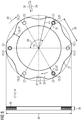
- FIG 5 is shown in a plan view and a longitudinal section of a lamella 16 according to a first embodiment.
- the plate 16 is essentially ring-shaped and, in an assembled state, is mounted in a plate clutch 10 essentially centered on its main axis of rotation 15.
- the lamella 16 comprises a plurality of lamella leaves 30 which are connected to one another in a substantially layer-like manner.
- the lamella 16 has a variable radial width 47 along a circumferential direction 43.
- the slat 16 is in FIG 5 on the end face 27 shown is divided essentially symmetrically with a pitch angle 39 of 120 °.
- the end face 27, as shown for one side of the plate 16, is the surface to which the area-specific power density of the plate clutch 10 is based.
- second fastening means 19 are attached, which are designed as nuts 21.
- the second fastening means 19 are connected to the lamella 16 via a material connection 23, which is designed as a welded connection.
- the second fastening means 19 are designed as nuts 21, which are mounted alternately on both end faces 27 of the lamella 16.
- the lamella 16 is bulged in a radially outer direction.
- a radially outer direction is shown by arrow 34 and a radially inner direction by arrow 36.
- Areas with a minimum radial width 29 are formed between the areas with the maximum radial width 32.
- a free slat length 38 is defined by a distance between two second fastening means 19, which are arranged adjacent to one another in the circumferential direction 43 and are fastened to different end faces 27 of the slat 16.
- the free plate length 38 is the region that is designed to be deformable and is therefore suitable for an offset between a first and a second flange 12, 14 in a plate clutch 10, such as in FIG 3 and FIG 4 outlined to record.
- the ratio between the minimum radial width 29 and the maximum radial width 32 for the lamella 16 is as follows FIG 5 up to 1.8.
- the entire radial width 47 is suitable for transmitting a tensile stress 26, by which a torque-transmitting one Connection between a first and a second flange 12, 14 of a multi-plate clutch 10, as in 1 to 4 shown, enables.
- the lamella 16 is designed to be continuous, that is to say free of recesses, at least in the region of the second fastening means 19, corresponding notch stresses that would require a larger dimensioning of the lamella 16 are avoided.
- the lamella 16 has a reduced outer diameter 40.
- the lamella 16 has a constant lamella thickness 35, viewed at least along the circumferential direction. As a result, the lamella 16 can be produced in a simple manner and, at the same time, a reduced outer diameter 40 can be achieved.
- FIG. 6 A second embodiment of the claimed slat 16 is shown in FIG FIG 6 shown in a top view and a longitudinal section.
- the plate 16 is essentially ring-shaped and, in an assembled state, is mounted in a plate clutch 10 essentially centered on its main axis of rotation 15.
- the lamella 16 comprises a plurality of lamella leaves 30 which are connected to one another in a substantially layer-like manner.
- the lamella 16 has a substantially constant radial width 47 along a circumferential direction 43.
- the slat 16 is in FIG 6 on the end face 27 shown is divided essentially symmetrically with a pitch angle 39 of 120 °.
- the second fastening means 19 on an end face 27 of the lamella 16, which are designed as nuts 21, are positioned essentially along this symmetrical division.
- the second fastening means 19 are connected via a material connection 23, which is designed as a welded connection, to the lamella 16.
- the second fastening means 19 are designed as nuts 21, which are mounted alternately on both end faces 27 of the lamella 16.
- the radial width 47 between the individual second fastening means 19 is essentially constant, so that the lamella 16 essentially has an annular shape.
- a free slat length 38 is defined by a distance between two second fastening means 19, which are arranged adjacent to one another in the circumferential direction 43 and are fastened to different end faces 27 of the slat 16.
- the free plate length 38 is the region which is designed to be deformable and is therefore suitable for an offset between a first and a second flange 12, 14 in a plate clutch 10, as for example in FIG FIG 3 and FIG 4 outlined to record. Due to the essentially constant radial width 47, a minimum radial width 29 of the lamella 16 corresponds to a maximum radial width 32 of the lamella 16. The relationship between the minimum and the maximum radial width 29, 32 in the lamella 16 is thus FIG 6 essentially 1.0.
- the entire radial width 47 is suitable for transmitting a tensile stress 26, through which a torque-transmitting connection between a first and a second flange 12 , 14 of a multi-plate clutch 10, as in 1 to 4 shown, enables.
- the lamella 16 is designed to be continuous, that is to say free of recesses, at least in the region of the second fastening means 19, corresponding notch tensions are avoided which would require a larger dimensioning of the lamella 16.
- the lamella 16 thus has a reduced outer diameter 40 overall.
- the lamella 16 has a constant lamella thickness 35, viewed at least along the circumferential direction. As a result, the lamella 16 is simple producible and at the same time a reduced outer diameter 40 can be achieved.
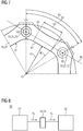
- FIG. 7 A section of a schematic end view of a third embodiment of a lamella 16 is shown in FIG FIG 7 pictured.
- second fastening means 19 are attached alternately on both sides, which are connected to the lamella 16 via a material connection 23.
- the second fastening means 19 are designed as nuts 21.
- Center points 65 of adjacent second fastening means 19 are connected in pairs by a connecting line 60.
- a section 63 of the lamella 16 carrying glass is formed along the connecting line 60 between the second fastening means 19.
- the glass-carrying section 63 becomes one in FIG. 1 subjected to the illustrated tensile stress 26 when a torque 25, as in FIG FIG. 1 shown, is transmitted.
- the glass-carrying section 63 is delimited radially on the outside by an outer contour 61 of the lamella 16.
- the glass-carrying section 63 is delimited radially on the inside by an inner contour 62 of the lamella 16.
- the glass-carrying section 63 is essentially symmetrical with respect to the connecting line 60.
- the inner contour 62 and the outer contour 61 of the lamella 16 between two second fastening means 19 are symmetrical to one another at least in sections.
- the outer contour 61 is essentially designed as an arcuate line concave with an outer diameter 40 of the lamella 16.
- the inner contour 62 is viewed through a variable inner diameter 49 along the circumferential direction 43 of the lamella 16.
- the glass-carrying section 63 merges along the circumferential direction 43 on both sides into transition areas 64 in which the second fastening means 19 are positioned.
- the shape of the glass-carrying section 63 results in an improved, more uniform stress distribution in the lamella 16. As a result, increased material utilization in the lamella 16 can be achieved, which in turn takes account of a lightweight construction concept.
- FIG 8 the structure of an industrial application 50 is shown schematically, which comprises a drive unit 52, which is designed to provide a torque 25 with which an output unit 56 can be operated.
- the drive unit 52 can be designed, for example, as an electric motor, internal combustion engine, hydraulic motor, or as a drive shaft.
- the output unit 56 in turn can be designed, for example, as an output shaft, a mill, vertical mill, sugar mill, cement mill, rock crusher, conveyor belt, pump, roller press, plate belt, tube mill, rotary kiln, rotating mechanism, agitator, lifting device, waste press or as a scrap press.
- a clutch 54 is mounted between the drive unit 52 and the output unit 56, through which the torque 25 can be transmitted from the drive unit 52 to the output unit 56.
- the clutch 54 is designed as a multi-plate clutch 10, which is designed according to at least one of the embodiments outlined above.
- the multi-plate clutch 10 is particularly compact and can be manufactured in a simple manner. As a result, a coupling 54 can be fitted between the drive unit 52 and the output unit 56 even in confined spaces. At the same time, the multi-plate clutch 10 offers an increased degree of service life and essentially no wear, which in turn increases the reliability in the operation of the industrial application 50.
Landscapes
- Engineering & Computer Science (AREA)
- General Engineering & Computer Science (AREA)
- Mechanical Engineering (AREA)
- Connection Of Plates (AREA)
- Mechanical Operated Clutches (AREA)
Abstract
Description
- Die Erfindung betrifft eine Lamellenkupplung, die über eine verbesserte Lamellenanbindung verfügt. Die Erfindung betrifft auch eine Industrie-Applikation, in der eine entsprechende Lamellenkupplung eingesetzt wird.
- Die bisher unveröffentlichte Europäische Patentanmeldung mit der Anmeldungsnummer
18154424.8-1012 - Das Dokument
EP 1 347 183 A1 offenbart eine Schweißmutter, die über symmetrisch angeordnete Abschnitte verfügt, an denen die Schweißmutter stoffschlüssig mit einer ebenen Unterlage verbindbar ist. Derartige Schweißmuttern sind im Fahrzeugbau einsetzbar. - In einer Vielzahl an technischen Anwendungen, in denen Antriebsleistung von einer Welle auf eine andere Welle zu übertragen ist, besteht Bedarf an leistungsfähigen Kupplungen, die kompakte Abmessungen aufweisen. Darüber hinaus wird angestrebt, dass eine entsprechende Kupplung einfach, schnell und kosteneffizient herzustellen sein soll. Ebenso wird für eine entsprechende Kupplung eine hohe Lebensdauer angestrebt. Der Erfindung liegt die Aufgabenstellung zugrunde, eine Kupplung bereitzustellen, die in zumindest einem der skizzierten Punkte eine Verbesserung bietet und in einer Vielzahl an Anwendungsgebieten, insbesondere verschiedenen Industrie-Applikationen, einsetzbar ist.
- Die Aufgabenstellung wird durch eine erfindungsgemäße Lamellenkupplung gelöst. Die Lamellenkupplung umfasst einen ersten und einen zweiten Flansch, die über eine Lamelle miteinander verbunden sind. Die Verbindung zwischen dem ersten und zweiten Flansch über die Lamelle ist drehmomentübertragend, so dass Wellenleistung vom ersten auf den zweiten Flansch oder umgekehrt übertragbar ist. Dabei ist die Lamelle mit dem ersten Flansch über ein erstes Befestigungsmittel lösbar verbunden, das zu einem Übertragen einer Zugkraft ausgebildet ist. Das erste Befestigungsmittel wirkt mit einem zweiten Befestigungsmittel zusammen, so dass beispielsweise die Zugkraft durch die Lamelle auf das zweite Befestigungsmittel übertragbar ist, und darüber auf das erste Befestigungsmittel. Das erste und zweite Befestigungsmittel bilden zusammen eine lösbare Verbindung aus, die ein zerstörungsfreies Trennen des ersten und zweiten Befestigungsmittels erlaubt. Erfindungsgemäß ist das zweite Befestigungsmittel über eine stoffschlüssige Verbindung mit der Lamelle verbunden. Die stoffschlüssige Verbindung kann dabei punktuell oder um das zweite Befestigungsmittel umlaufend ausgebildet sein. Die Einleitung einer Zugkraft und/oder einer Querkraft vom ersten Befestigungsmittel über das zweite Befestigungsmittel in die Lamelle erfordert damit keine weitergehenden Anpassungen der Lamelle. Insbesondere sind Einkerbungen, Ausnehmungen und andere Materialrücknahmen an der Lamelle entbehrlich, die beispielsweise zur Bereitstellung eines Formschlusses oder eines Reibschlusses notwendig sind. Stattdessen ist das zweite Befestigungsmittel selbst dazu ausgebildet, eine Zugkraft und/oder Querkraft in die Lamelle einzuleiten. Derartige Beanspruchungen sind beispielweise durch eine Drehbewegung des ersten Flansches relativ zum zweiten Flansch, oder durch einen Axialversatz oder Radialversatz zwischen dem ersten und zweiten Flansch hervorrufbar. Somit ist die Lamelle erfindungsgemäß einfacher konstruierbar und kann dazu beispielsweise entlang ihres gesamten Umfangs einen unverzweigten Querschnitt aufweisen. Dies erlaubt eine stärkere Ausnutzung des für die Lamelle eingesetzten Materials, und damit eine gewichtsparende und platzsparende Bauform der Lamelle selbst. Ebenso ist durch die verbesserte Materialausnutzung auch eine erhöhte Lebensdauer der Lamelle erreichbar. Dadurch, dass die Lamelle einer Lamellenkupplung die Größe, insbesondere den jeweiligen Durchmesser, des ersten und zweiten Flansches bestimmt, ist es möglich, die erfindungsgemäße Lamellenkupplung in puncto Außendurchmesser kompakt auszubilden.
- In einer weiteren Ausführungsform der beanspruchten Lamellenkupplung kann das erste Befestigungsmittel als Schraube, als Bolzen, Gewindebolzen, oder als Passschraube ausgebildet sein. Derartige Ausführungsformen des ersten Befestigungsmittels sind dazu geeignet, eine Zugkraft, eine Druckkraft, und/oder eine Querkraft aufzunehmen und sind zerstörungsfrei vom ersten Flansch und/oder der Lamelle lösbar. Unter dem ersten Befestigungsmittel ist auch jegliches andere Konstruktionselement zu verstehen, das eine entsprechende lösbare Verbindung zwischen der Lamelle und dem ersten Flansch erlaubt. Alternativ oder ergänzend kann das zweite Befestigungsmittel als Mutter oder als Schweißmutter ausgebildet sein. Eine Mutter oder Schweißmutter stellt ein zweites Befestigungsmittel dar, das komplementär zum ersten Befestigungsmittel ausgebildet ist und vom ersten Befestigungsmittel zerstörungsfrei lösbar ist. Ferner sind Muttern und Schweißmuttern in einfacher Weise stoffschlüssig an einer Lamelle anbringbar. Unter einem zweiten Befestigungsmittel ist auch jegliches Konstruktionselement zu verstehen, das komplementär zum ersten Befestigungsmittel wirkt, von diesem lösbar ausgebildet ist und mit der Lamelle stoffschlüssig verbindbar ist. Derartige erste und zweite Befestigungsmittel sind in einer breiten Spanne an Abmessungen und Gütekategorien einfach verfügbar und sind damit einfach an die Erfordernisse einer Lamellenkupplung konstruktiv anpassbar. Ferner bieten die skizzierten ersten und zweiten Befestigungsmittel in einfacher Weise eine mechanisch beanspruchbare Verbindung, die zur Übertragung einer Zugkraft, einer Druckkraft und/oder einer Querkraft geeignet ist.
- Des Weiteren kann in der Lamellenkupplung die stoffschlüssige Verbindung zwischen der Lamelle und dem zweiten Befestigungsmittel als eine Schweißverbindung, eine Lötverbindung, eine Hartlötverbindung, oder als Klebverbindung ausgebildet sein. Des Weiteren sind auch Kombinationen entsprechender stoffschlüssiger Verbindungen möglich. Schweißverbindungen, Lötverbindungen und Hartlötverbindungen bieten ein hohes Maß an Festigkeit, wenn die Lamelle und/oder das zweite Befestigungsmittel zumindest abschnittsweise aus einem metallischen Werkstoff hergestellt sind. Eine Schweißverbindung bietet hierbei eine erhöhte Festigkeit. Eine Lötverbindung oder Hartlötverbindung wiederum wird mit geringeren Prozesstemperaturen hergestellt als eine Schweißverbindung, so dass Gefügeänderungen in der Lamelle reduziert werden. Klebverbindungen wiederum sind in besonders einfacher und wirtschaftlicher Weise herstellbar und bieten die niedrigsten Prozesstemperaturen. Solche stoffschlüssige Verbindungen sind mit hoher Qualität und Prozesssicherheit herstellbar und sind einfach in einen industriellen Fertigungsprozess integrierbar. Damit kann die beanspruchte Lamellenkupplung in einfacher Weise hergestellt werden. Die beanspruchte Lamellenkupplung ist somit bei einer Vielzahl an Werkstoffen und Werkstoffkombinationen herstellbar und somit für unterschiedliche Einsatzzwecke anpassbar.
- Darüber hinaus kann die stoffschlüssige Verbindung zwischen der Lamelle und dem zweiten Befestigungsmittel durch Elektronenstrahlschweißen oder Laserschweißen hergestellt sein. Insbesondere beim Elektronenstrahlschweißen liegt ein reduzierter Wärmeeintrag in die Lamelle vor. Die Lamelle kann beispielsweise aus einem Federstahl hergestellt sein, dessen Elastizität durch übermäßigen Wärmeeintrag hergesetzt werden kann. Bei einer stoffschlüssigen Verbindung zwischen der Lamelle und dem zweiten Befestigungsmittel, die durch Elektronenstrahlschweißen hergestellt ist, werden die Materialeigenschaften des Werkstoffs der Lamelle bewahrt. Die Lamelle ist folglich weiterhin aus Werkstoffen herstellbar, die durch Wärmeeintrag degradierbar sind. Ein Wechsel zu einem kostenintensiven und anspruchsvoller zu verarbeitenden Werkstoff für die Lamelle ist damit vermeidbar. Darüber hinaus ist ein Elektronenstrahlschweißen schnell durchführbar, was die Herstellung der beanspruchten Lamellenkupplung vereinfacht. Alternativ oder ergänzend kann die stoffschlüssige Verbindung auch durch ein Widerstandspunktschweißen hergestellt werden. Ein Widerstandspunktschweißen bietet eine erhöhte Energieeffizienz, einen geringen Bauteilverzug und kommt ohne zusätzliche Materialien aus.
- Ferner kann die Lamelle zumindest im Bereich des zweiten Befestigungsmittels ausnehmungsfrei ausgebildet sein. Darunter ist zu verstehen, dass in der Lamelle unmittelbar am zweiten Befestigungsmittel oder in dessen Umgebung keine Bohrungen, Einkerbungen oder Einschnürungen des Querschnitts der Lamelle vorliegen. Dadurch, dass im Bereich des zweiten Befestigungsmittels insbesondere keine Bohrung ausgebildet ist, weist die Lamelle dort einen unverzweigten Querschnitt auf. Beispielsweise liegen an Bohrungen oder Einschnürungen Formzahlen und/oder Kerbwirkungszahlen vor, die größer als Eins sind. Die beanspruchte Lösung erlaubt es, durch entsprechende Gestaltung der Lamelle und/oder der Anbindung des Befestigungsmittels die Formzahl und/oder die Kerbwirkungszahl an der entsprechenden Stelle gezielt zu reduzieren. Ebenso werden abträgliche Effekte infolge einer Lochleibung vermieden. Die beanspruchte Lamellenkupplung erlaubt es, derartige Aspekte bei der Auslegung der Lamelle zu vernachlässigen und so die Lamelle kompakter zu konstruieren. Dies wiederum erlaubt es, die Lamellenkupplung platzsparender zu bauen.
- In einer weiteren Ausführungsform ist der zweite Flansch über ein erstes Befestigungsmittel mit der Lamelle lösbar verbunden. Dieses erste Befestigungsmittel wiederum ist lösbar mit einem zweiten Befestigungsmittel verbunden, das durch eine stoffschlüssige Verbindung mit der Lamelle verbunden ist. Dadurch wird die Verbindung zwischen dem ersten Flansch über das erste und zweite Befestigungsmittel mit der Lamelle auf den zweiten Flansch übertragen. Hierdurch ist insbesondere eine durchgehende Anwendung des Prinzips der beanspruchten Lösung in einer Lamellenkupplung möglich. Des Weiteren kann ein Abstand zwischen zwei benachbarten zweiten Befestigungsmitteln, die an entgegengesetzten Seiten der Lamelle angebracht sind, im Wesentlichen einer freien Lamellenlänge entsprechen. Unter einer freien Lamellenlänge ist, entlang einer Umfangsrichtung der Lamelle betrachtet, der Abschnitt der Lamelle zu verstehen, der dazu geeignet ist, bei einer Torsionsbeanspruchung der Lamellenkupplung in Umfangrichtung Zugkräfte und dabei, durch Wellenversatz erzwungene Rückstellkräfte, biegeweich zu übertragen. Der Wellenversatz führt dabei zu einer axialen Verlagerung des ersten und zweiten Flansches bzw. zu einer Neigung der Flansche zueinander. Unter Torsionsbeanspruchung der Lamellenkupplung bei gleichzeitiger Verlagerung liegt eine im Wesentlichen S-förmige Verformung der Lamelle zwischen zwei benachbarten zweiten Befestigungsmitteln vor. Je länger die freie Lamellenlänge ist, umso höhere Torsionsbeanspruchungen bei Versatz kann die Lamelle aufnehmen. Ferner bestimmt die freie Lamellenlänge die Verlagerungsfähigkeit der Lamellenkupplung, also die Fähigkeit, Axialversätze und/oder Radialversätze zwischen dem ersten und zweiten Flansch aufzunehmen. Auch die Fähigkeit zum Aufnehmen von Winkelversätzen zwischen dem ersten und zweiten Flansch gehört zur Versatzfähigkeit. Je höher die Versatzfähigkeit der Lamellenkupplung ist, umso robuster ist sie im Betrieb und für entsprechend hochbeanspruchende Anwendungen geeignet. Insbesondere erlaubt die beanspruchte Lösung einen bestimmungsgemäßen dauerhaften Betrieb, bei dem ein Nenndrehmoment vorliegt und gleichzeitig eine Winkelversatz von bis zu 1° und gleichzeitig ein Axialversatz zwischen dem ersten und zweiten Flansch von bis zu 2 mm. Die stoffschlüssigen Verbindungen zwischen den zweiten Befestigungsmitteln und der Lamelle sind jeweils kompakt ausgebildet, so dass die freie Lamellenlänge gegenüber bekannten, also nicht erfindungsgemä-βen, gleich dimensionierten Lamellenkupplungen erhöht ist.
- Bei der beanspruchten Lamellenkupplung kann auch zwischen dem zweiten Befestigungsmittel und der Lamelle ein Distanzelement angeordnet werden. Die stoffschlüssige Verbindung ist dabei zwischen der Lamelle und dem Distanzelement ausgebildet. Das Distanzelement ist hierbei wiederum mit dem zweiten Befestigungselement verbunden. Die Verbindung zwischen dem Distanzelement und dem zweiten Befestigungselement kann dabei lösbar oder unlösbar ausgebildet sein, beispielsweise als stoffschlüssige Verbindung. Das Distanzelement kann als Scheibe, Buchse, Hülse, Unterlegscheibe, oder als Unterlegscheibenstapel ausgebildet sein. Infolgedessen sind die Distanzelemente als robuste Konstruktionselemente ausgebildet. Das zugehörige zweite Befestigungsmittel ist damit sicher vom Distanzelement trennbar und durch ein entsprechendes Ersatzteil, also ein neues zweites Befestigungsmittel, ersetzbar. Insbesondere kann bei einer solchen Reparatur ein Wärmeeintrag in die Lamelle minimiert oder verhindert werden. Dies erlaubt insgesamt eine einfache und schnelle Reparatur der beanspruchten Lamellenkupplung. Darüber hinaus ist das Distanzelement dazu geeignet, eine Länge des ersten und/oder zweiten Befestigungsmittels zu bestimmen. Des Weiteren ist ein derartiges Distanzelement in einem separaten Fertigungsschritt präzise positionierbar. Die daraus resultierende hohe Maßhaltigkeit erlaubt es, die technischen Vorteile der beanspruchten Lamellenkupplung in erhöhtem Maß zu erzielen.
- Alternativ kann die stoffschlüssige Verbindung unmittelbar zwischen der Lamelle und dem zweiten Befestigungsmittel ausgebildet sein. Insbesondere kann eine solche unmittelbare Verbindung als eine stoffschlüssige Verbindung, beispielsweise als Schweißverbindung, ausgebildet sein. Dadurch wird die Anzahl an Komponenten und Fertigungsschritten reduziert und die Herstellung der Lamellenkupplung vereinfacht.
- In einer weiteren Ausführungsform der Lamellenkupplung weist diese eine flächenspezifische Leistungsdichte von 100 MW/m2 bis 400 MW/m2, bevorzugt 150 MW/m2 bis 350 MW/m2, besonders bevorzugt von 160 MW/m2 bis 280 MW/m2 auf.
- Die flächenspezifische Leistungsdichte ist dabei das Verhältnis zwischen der zulässigen Nennleistung der Lamellenkupplung und der radialen Gesamtquerschnittsfläche der Kupplung, also der Oberfläche der Lamelle im Querschnitt. Die Oberfläche der Lamelle wird dabei nur auf einer Seite berücksichtigt. Die flächenspezifische Leistungsdichte wird formelmäßig definiert durch:

- Φ:= flächenspezifische Leistungsdichte
- M:= Nenndrehmoment
- ω:= Nenndrehzahl
- da:= Außendurchmesser der Lamelle
- di:= Innendurchmesser der Lamelle
- Die beanspruchte Lösung bietet gegenüber den Lösungen aus dem Stand der Technik eine gesteigerte flächenspezifische Leistungsdichte. Damit ist die beanspruchte Lamellenkupplung auch in Anwendungen einsetzbar, bei denen hohe Anforderungen an die Beanspruchbarkeit einer Kupplung gestellt werden und gleichzeitig geringe Abmessungen erforderlich sind.
- Darüber hinaus kann bei der beanspruchten Lamellenkupplung das erste Befestigungsmittel, das am ersten und/oder zweiten Flansch aufgenommen ist, zum Aufnehmen einer Querkraft ausgebildet sein. Neben dem Übertragen einer Zugkraft wird dadurch im Betrieb ein Verformen des ersten Befestigungsmittels entlang einer Umfangsrichtung reduziert oder minimiert. Dadurch wird die Lamelle im Wesentlichen entlang einer Umfangsrichtung beansprucht. Je höher die Verformung des erstens Befestigungsmittels ist, umso stärker ist die S-förmige Verformung der Lamelle zwischen zwei zweiten Befestigungsmitteln, die an unterschiedlichen Seite der Lamelle angebracht sind. Je geringer die S-förmige Verformung ist, umso geringer ist in einem entsprechend gebogenen Abschnitt der Lamelle die mechanisehe Beanspruchung, was wiederum zu einer erhöhten Lebensdauer der Lamelle führt.
- In einer weiteren Ausführungsform der beanspruchten Lamellenkupplung weist die Lamelle eine maximale Radialbreite auf, die dem 1,0-fachen bis 1,8-fachen, bevorzugt dem 1,0-fachen bis 1,5-fachen, besonders bevorzugt dem 1,0-fachen bis 1,2-fachen einer minimalen Radialbreite der Lamelle entspricht. Unter der Radialbreite ist, entlang einer Axialrichtung bezogen auf eine Drehachse der Lamellenkupplung betrachtet, eine Breite einer umlaufenden Oberfläche auf einer Seite der Lamelle zu verstehen, die dem ersten oder zweiten Flansch zugewandt ist. Die Lamelle weist dementsprechend eine im Wesentlichen konstante Radialbreite auf, die im bestimmungsgemäßen Betrieb zwischen zwei benachbarten zweiten Befestigungsmitteln in Umfangsrichtung im Wesentlichen einer Zugbeanspruchung unterworfen ist. Die Lamelle ist dabei zumindest jeweils im Bereich eines zweiten Befestigungsmittels frei von Ausnehmungen oder Bohrungen ausgebildet, so dass lokale Erhöhungen der Radialbreite entbehrlich sind. Folglich weist die Lamelle in der beanspruchten Lamellenkupplung einen reduzierten Außendurchmesser auf.
- Des Weiteren kann die Lamelle in der beanspruchten Lamellenkupplung durchgängig eine im Wesentlichen durchgängig konstante Dicke aufweisen. Die Lamelle ist in der beanspruchten Lamellenkupplung im Wesentlichen streifenförmig ausbildbar. Dies ist einfacher und wirtschaftlicher in der Herstellung als eine Lamelle, die über lokale Aufdickungen verfügt. Die Lamelle ist beispielsweise aus einem Blech ausstanzbar und kann weitestgehend automatisch hergestellt werden. Das Gleiche gilt analog auch für Lamellen, die entsprechend schichtweise miteinander verbundene Lamellenblätter aufweisen. Auch hierdurch wird die Wirtschaftlichkeit der beanspruchten Lamellenkupplung weiter erhöht.
- In einer weiteren Ausführungsform der beanspruchten Lamellenkupplung liegt zwischen zwei, in Umfangsrichtung betrachtet, benachbarten zweiten Befestigungsmitteln ein zuglasttragender Abschnitt vor. In einen derartigen Abschnitt wird im Betrieb die Zugbeanspruchungen eingeleitet, die durch das zu übertragende Drehmoment in der Lamelle hervorgerufen werden. Der zuglasttragende Abschnitt entspricht zumindest teilweise in Umfangsrichtung dem Teil der Lamelle, der sich zwischen den zweiten Befestigungsmitteln, die auf unterschiedlichen Seiten der Lamelle angebracht sein können, befindet. Zwischen den zwei benachbarten zweiten Befestigungsmitteln ist eine Verbindungslinie darstellbar, die im Wesentlichen die Mittelpunkte der zweiten und der zugeordneten ersten Befestigungsmittel miteinander verbindet. Der zuglasttragende Abschnitt der Lamelle ist dabei im Wesentlichen symmetrisch zur Verbindungslinie ausgebildet. Der zuglastragende Abschnitt ist radial innen von einer Innenkontur und radial außen von einer Außenkontur begrenzt. Die Innenkontur und die Außenkontur gehen entlang der Umfangsrichtung beidseitig in einen Anbindungsabschnitt über, in der jeweils ein zweites Befestigungsmittel mit der Lamelle stoffschlüssig verbunden ist. Dies erlaubt eine gleichmäßige Einleitung der Zugbeanspruchung in die Lamelle, bei der lokale Spannungserhöhungen reduziert werden.
- Die zugrundeliegende Aufgabenstellung wird auch durch eine erfindungsgemäße Industrie-Applikation gelöst. Die Industrie-Applikation weist eine Antriebseinheit auf, die über Kupplung mit einer Abtriebseinheit drehmomentübertragend verbunden ist. Die Antriebseinheit kann beispielsweise als Ausgangswelle eines Elektromotors ausgebildet sein. Die Abtriebseinheit wiederum kann beispielsweise als Eingangswelle einer mechanischen Anwendung, wie beispielsweise einer Pumpe, ausgebildet sein. Infolge eines inkonstanten Verhaltens der Antriebseinheit und/oder der Abtriebseinheit ist die Kupplung im Betrieb Axialversätzen, Radialversätzen und/oder Winkelversätzen unterworfen. Ein inkonstantes Verhalten der Antriebseinheit kann beispielsweise durch ein Anfahren verursacht werden, ein inkonstantes Verhalten der Abtriebseinheit beispielsweise durch ein Leerlaufen einer Pumpe. Die Kupplung ist hierbei als eine Lamellenkupplung gemäß einer der oben skizzierten Ausführungsformen ausgebildet.
- Die Erfindung wird im Folgenden anhand einzelner Ausführungsformen beschrieben. Die Merkmale der einzelnen Ausführungsformen sind dabei untereinander kombinierbar. Die Figuren sind insoweit in gegenseitiger Ergänzung zu lesen, dass gleiche Bezugszeichen in den Figuren auch die gleiche technische Bedeutung haben. Es zeigen im Einzelnen:
- FIG 1
- eine Detailansicht einer ersten Ausführungsform der beanspruchten Lamellenkupplung;
- FIG 2
- eine Detailansicht einer zweiten Ausführungsform der beanspruchten Lamellenkupplung;
- FIG 3
- eine schematische Seitenansicht einer Ausführungs-form der beanspruchten unbelasteten Lamellenkupplung;
- FIG 4
- eine schematische Seitenansicht der Lamellenkupplung aus
FIG 3 unter einer Belastung; - FIG 5
- eine schematische Stirnansicht und ein Längsschnitt einer ersten Ausführungsform einer Lamelle;
- FIG 6
- eine schematische Stirnansicht und ein Längsschnitt einer zweiten Ausführungsform einer Lamelle;
- FIG 7
- einen Ausschnitt einer schematischen Stirnansicht einer dritten Ausführungsform einer Lamelle;
- FIG 8
- einen schematischen Aufbau einer Ausführungsform einer beanspruchten Industrie-Applikation.
-
FIG 1 zeigt schematisch eine Detailansicht einer ersten Ausführungsform einer erfindungsgemäßen Lamellenkupplung 10 in einem Längsschnitt. Die Lamellenkupplung 10 weist einen ersten und einen zweiten Flansch 12, 14 auf, die sich entlang einer Hauptdrehachse 15 gegenüberstehen. Über den ersten Flansch 12 wird ein Drehmoment 25 in die Lamellenkupplung 10 eingeleitet, das auf den zweiten Flansch 14 zu übertragen ist. Zwischen dem ersten und zweiten Flansch 12, 14 ist dazu eine Lamelle 16 vorgesehen, die eine Mehrzahl an Lamellenblättern 30 umfasst. Im ersten Flansch 12 ist eine Ausnehmung 18 ausgebildet, in der ein erstes Befestigungsmittel 17 aufgenommen ist. Die Ausnehmung 18 ist an der Lamellenkupplung 10 in einem radial äußeren Bereich ausgebildet. Eine radial äußere Richtung ist inFIG 1 durch den Pfeil 34 dargestellt, eine radial innere Richtung durch den Pfeil 36. Das erste Befestigungsmittel 17 ist als Schraube 20 ausgebildet. Das erste Befestigungsmittel 17 erstreckt sich durch die Ausnehmung 18 und ist vom ersten Flansch 12 lösbar. Ein dem zweiten Flansch 14 zugewandtes Ende des ersten Befestigungsmittels 17 ist mit einem zweiten Befestigungsmittel 19 lösbar verbunden. Das zweite Befestigungsmittel 19 ist dabei als Mutter 21 ausgebildet. Im montierten Zustand sind eine Zugkraft 22 vom zweiten Befestigungsmittel 19 auf das erste Befestigungsmittel 19 übertragbar, wobei das erste Befestigungsmittel 17 zu einem Abstützen am ersten Flansch 12 ausgebildet ist. Ferner ist das zweite Befestigungsmittel 19 dazu ausgebildet, sich in einer Axialrichtung, also entlang der Hauptdrehachse 15, an einem Anschlag 24 an ersten Flansch 12 abzustützen. Der Anschlag 24 umfasst unter anderem eine Begrenzung der Ausnehmung 18 auf einer axial inneren Stirnseite 13 des ersten Flanschs 12, in der das erste Befestigungsmittel 17 aufgenommen ist. Eine axial innere Richtung inFIG 1 durch die Pfeile 33 dargestellt, eine axial äußere Richtung durch die Pfeile 31. Im montierten Zustand wird das zweite Befestigungsmittel 19 durch das erste Befestigungsmittel 17 an den ersten Flansch 12 gedrückt. - Das zweite Befestigungsmittel 19 ist dabei an einer Stirnfläche 27 der Lamelle 16 angeordnet und mit der Lamelle 16 durch eine stoffschlüssige Verbindung 23 verbunden. Die stoffschlüssige Verbindung 23 ist als Schweißverbindung ausgebildet und ist durch Elektronenstrahlschweißen herstellbar. Ferner ist die stoffschlüssige Verbindung 23 punktuell oder um das zweite Befestigungsmittel 19 umlaufend ausbildbar. Die stoffschlüssige Verbindung 23 ist unmittelbar zwischen dem zweiten Befestigungsmittel 19 und der Lamelle 16 hergestellt. Infolge der stoffschlüssigen Verbindung 19 und des ersten Befestigungsmittels 17, das in der Ausnehmung 18 aufgenommen ist, wird durch ein Drehmoment 25, das auf den ersten Flansch 12 einwirkt, in der Lamelle 16 eine Zugbeanspruchung 26 hervorgerufen, die wiederum auf das erste Befestigungsmittel 17 als Querkraft 48 einwirkt. Dadurch ist das Drehmoment 25 vom ersten Flansch 12 auf den zweiten Flansch 14 übertragbar. Des Weiteren ist die in der Lamelle 16 hervorgerufene Zugbeanspruchung 26 durch das erste Befestigungsmittel 17 als Biegebeanspruchung 41 aufnehmbar. Das zweite Befestigungsmittel 19 weist einen geringen Durchmesser 42 auf, durch den eine in
FIG 3 näher beschriebene freie Lamellenlänge 38 erhöht wird. Die Lamelle 16 ist im Bereich des zweiten Befestigungsmittels 19 frei von Bohrungen oder Ausnehmungen. Damit ist die Lamelle 16 auch frei von Spannungserhöhungen, die sich infolge von Kerbspannungen bei Bohrungen ergeben. Infolgedessen ist eine mechanische Tragfähigkeit der Lamelle 16 stärker ausnutzbar. Dadurch, dass die stoffschlüssige Verbindung 23 unmittelbar zwischen der Lamelle 16 und dem zweiten Befestigungsmittel 19 hergestellt ist, erfordert die Ausführungsform gemäßFIG 1 eine reduzierte Anzahl an Bauteilen und ist dadurch wirtschaftlich herstellbar. Durch die verbesserter Ausnutzung des für die Lamelle 16 eingesetzten Materials ist die Lamelle 16 kompakt ausbildbar. Infolgedessen weist die Lamelle 16 einen gegenüber den aus dem Stand der Technik bekannten Lösungen einen reduzierten Außendurchmesser 40 auf. Der Außendurchmesser 40 stellt dabei auch den Außendurchmesser 40 der Lamellenkupplung 10 dar. - In
FIG 2 ist schematisch eine Detailansicht einer ersten Ausführungsform einer erfindungsgemäßen Lamellenkupplung 10 in einem Längsschnitt gezeigt. Die Lamellenkupplung 10 weist einen ersten und einen zweiten Flansch 12, 14 auf, die sich entlang einer Hauptdrehachse 15 gegenüberstehen. Über den ersten Flansch 12 wird ein Drehmoment 25 in die Lamellenkupplung 10 eingeleitet, das auf den zweiten Flansch 14 zu übertragen ist. Zwischen dem ersten und zweiten Flansch 12, 14 ist dazu eine Lamelle 16 angeordnet, die eine Mehrzahl an Lamellenblättern 30 umfasst. Im ersten Flansch 12 ist eine Ausnehmung 18 ausgebildet, in der ein erstes Befestigungsmittel 17 aufgenommen ist. Die Ausnehmung 18 ist an der Lamellenkupplung 10 in einem radial äußeren Bereich ausgebildet. Eine radial äußere Richtung ist inFIG 2 , analog zuFIG 1 , durch den Pfeil 34 dargestellt, eine radial innere Richtung durch den Pfeil 36. Das erste Befestigungsmittel 17 ist als Schraube 20 ausgebildet ist. Das erste Befestigungsmittel 17 erstreckt sich durch die Ausnehmung 18 und ist vom ersten Flansch 12 lösbar. Ein dem zweiten Flansch 14 zugewandtes Ende des ersten Befestigungsmittels 17 ist mit einem zweiten Befestigungsmittel 19 lösbar verbunden. Das zweite Befestigungsmittel 19 ist dabei als Mutter 21 ausgebildet. Im montierten Zustand sind eine Zugkraft 22 vom zweiten Befestigungsmittel 19 auf das erste Befestigungsmittel 19 übertragbar, wobei das erste Befestigungsmittel 17 zu einem Abstützen am ersten Flansch 12 ausgebildet ist. Ferner ist das zweite Befestigungsmittel 19 dazu ausgebildet, sich in einer Axialrichtung, also entlang der Hauptdrehachse 15, an einem Anschlag 24 an ersten Flansch 12 abzustützen. Der Anschlag 24 umfasst unter anderem eine Begrenzung der Ausnehmung 18 auf einer axial inneren Stirnseite 13 des ersten Flanschs 12, in der das erste Befestigungsmittel 17 aufgenommen ist. Eine axial innere Richtung inFIG 2 durch die Pfeile 33 dargestellt, eine axial äußere Richtung durch die Pfeile 31. Im montierten Zustand wird das zweite Befestigungsmittel 19 durch das erste Befestigungsmittel 17 an den ersten Flansch 12 gedrückt. - Das zweite Befestigungsmittel 19 ist dabei an einem Distanzelement 28 angeordnet, das wiederum an einer Stirnfläche 27 der Lamelle 16 angeordnet und mit der Lamelle 16 durch eine stoffschlüssige Verbindung 23 verbunden. Das zweite Befestigungselement 19 ist dabei über eine Distanzelement-Anbindung 45 mit dem Distanzelement 28 verbunden. Die Distanzelement-Anbindung 45 ist als stoffschlüssige Verbindung 23 ausgebildet, die beispielsweise durch Schweißen, insbesondere Elektronenstrahlschweißen, herstellbar ist. Das Distanzelement 28 ist als im Wesentlichen zylindrische Buchse 46 ausgebildet. Das Distanzelement 28 wiederum ist über eine stoffschlüssige Verbindung 23, die auch durch Schweißen, insbesondere Elektronenstrahlschweißen, herstellbar ist. Durch das Distanzelement 28 ist eine axiale Position der Lamelle 16 einstellbar. Das Distanzelement 46 ist in einem separaten Herstellungsschritt auf der Lamelle 16 befestigbar und so eine hohe Positionsgenauigkeit für das Distanzelement 46 erzielbar. Basierend hierauf ist eine hohe Positionsgenauigkeit für das zweite Befestigungsmittel 17 erzielbar. Das Distanzelement 28 weist einen Außendurchmesser 44 auf, durch den eine freie Lamellenlänge 38, wie beispielsweise in
FIG 3 dargestellt, bestimmt ist. Ferner erlaubt das Distanzelement 46 eine großflächigere Anbindung des zweiten Befestigungsmittels 19 an die Lamelle 16, was wiederum eine erhöhte konstruktive Freiheit bietet. Infolgedessen besteht für die Anbindung des zweiten Befestigungsmittels 19 und der Lamelle 16 die Möglichkeit einer Gestaltoptimierung. - Ferner ist die stoffschlüssige Verbindung 23 punktuell oder um das zweite Befestigungsmittel 19 oder das Distanzelement 46 umlaufend ausbildbar. Die stoffschlüssige Verbindung 23 ist zwischen dem Distanzelement 28 und der Lamelle 16 hergestellt. Dadurch dient die stoffschlüssige Verbindung 23 zwischen der Lamelle 16 und des Distanzelement 28 auch der Befestigung des zweiten Befestigungsmittels 19 an der Lamelle 19. Folglich wird im ersten Befestigungsmittel 17, das in der Ausnehmung 18 aufgenommen ist, durch ein Drehmoment 25, das auf den ersten Flansch 12 einwirkt, in der Lamelle 16 eine Zugbeanspruchung 26 hervorgerufen, die auf das erste Befestigungsmittel 17 als Querkraft 48 einwirkt. Dadurch ist das Drehmoment 25 vom ersten Flansch 12 auf den zweiten Flansch 14 übertragbar. Des Weiteren ist die in der Lamelle 16 hervorgerufene Zugbeanspruchung 26 durch das erste Befestigungsmittel 17 als Biegebeanspruchung 41 aufnehmbar. Das zweite Befestigungsmittel 19 weist einen geringen Durchmesser 42 auf, durch den eine in
FIG 3 näher beschriebene freie Lamellenlänge 38 erhöht wird. Die Lamelle 16 ist im Bereich des zweiten Befestigungsmittels 19 frei von Bohrungen oder Ausnehmungen. Damit ist die Lamelle 16 auch frei von Spannungserhöhungen, die sich infolge von Kerbspannungen bei Bohrungen ergeben. Infolgedessen ist eine mechanische Tragfähigkeit der Lamelle 16 stärker ausnutzbar. Dadurch, dass die Lamelle 16 mittelbar über das Distanzelement 28 mit dem zweiten Befestigungsmittel 19 verbunden ist, bietet die Ausführungsform gemäßFIG 2 eine verbesserte Präzision in der Fertigung. Insbesondere ist das Distanzelement 28 in einem separaten Herstellungsschritt mit hoher Positionsgenauigkeit auf der Lamelle 16 befestigbar. Zusätzlich ist das Distanzelement 28 nach dem Verbinden mit der Lamelle 16 axial anpassbar, beispielsweise durch Fräsen oder Drehen. Dadurch ist insgesamt eine hohe Maßhaltigkeit bei der Lamellenkupplung 10 erzielbar. Durch die verbesserter Ausnutzung des für die Lamelle 16 eingesetzten Materials ist die Lamelle 16 kompakt ausbildbar. Infolgedessen weist die Lamelle 16 einen gegenüber den aus dem Stand der Technik bekannten Lösungen einen reduzierten Außendurchmesser 40 auf. Der Außendurchmesser 40 stellt dabei auch den Außendurchmesser 40 der Lamellenkupplung 10 dar. - Darüber hinaus ist in
FIG 3 eine weitere Ausführungsform der beanspruchten Lamellenkupplung 10 in einer Seitenansicht dargestellt. Die Lamellenkupplung 10 weist einen ersten Flansch 12 und einen zweiten Flansch 14 auf, über die ein Drehmoment 25 zu übertragen ist. Der erste und zweite Flansch 12, 14 weisen jeweils einander zugewandt eine Stirnseite 13 auf. Zwischen den Stirnseiten 13 der ersten und zweiten Flansches 12, 14 ist eine Lamelle 16 angeordnet, die eine Mehrzahl an Lamellenblättern 30 aufweist. Im ersten und zweiten Flansch 12, 14 sind jeweils entlang einer Axialrichtung, die sich parallel zu einer Hauptdrehachse 15 der Lamellenkupplung 10 erstreckt, eine Mehrzahl an Ausnehmungen 18 ausgebildet. In den Ausnehmungen 18 ist jeweils ein erstes Befestigungsmittel 17 lösbar aufgenommen. Dabei ist das erste Befestigungsmittel 17 als Schraube 20 ausgebildet. Ferner sind die jeweiligen ersten Befestigungsmittel 17 dazu ausgebildet, eine Zugkraft 22, wie inFIG 1 undFIG 2 skizziert, aufzunehmen. Die ersten Befestigungsmittel 17 wirken jeweils mit einem zweiten Befestigungsmittel 19 zusammen, das an der Lamelle 16 befestigt ist. Das erste und zweite Befestigungsmittel 17, 19 sind lösbar mit einander verbunden, wobei das zweite Befestigungsmittel 19 dazu ausgebildet ist, eine Zugkraftbeanspruchung in das erste Befestigungsmittel 17 einzuleiten. Die zweiten Befestigungsmittel 19 sind inFIG 3 ferner als Muttern 21 ausgebildet. Die zweiten Befestigungsmittel 19 sind ferner über eine stoffschlüssige Verbindung 23 mit der Lamelle 16 verbunden. Die stoffschlüssige Verbindung 23 ist als Schweißverbindung ausgebildet und ist unmittelbar an einer Stirnfläche 27 der Lamelle 16 ausgebildet. - Entlang einer Umfangsrichtung der Lamelle 16 betrachtet, ist die Lamelle 16 alternierend an unterschiedlichen Stirnflächen 27 mit zweiten Befestigungsmitteln 19 versehen, die jeweils wiederum mit ersten Befestigungsmitteln 17 lösbar verbunden sind. Die entsprechenden ersten Befestigungsmittel 17 sind, entlang der Umfangsrichtung der Lamelle 16 betrachtet, in Ausnehmungen 18 alternierend am ersten und zweiten Flansch 12, 14 aufgenommen. Die Lamelle 16 wiederum ist zum Aufnehmen einer Zugbeanspruchung 26 ausgebildet, durch die zwischen dem ersten und zweiten Flansch 12, 14 eine drehmomentübertragende Verbindung herstellbar ist. Zwischen den zweiten Befestigungsmitteln 19 auf den unterschiedlichen Stirnflächen 27 liegt ein Abschnitt der Lamelle 16, durch den eine freie Lamellenlänge 38 definiert ist. Die freie Lamellenlänge 38 ist durch die kompakte Form der zweiten Befestigungsmittel 19 gegenüber bekannten Lamellenkupplungen erhöht. Die Abschnitte, die die freie Lamellenlänge 38 definieren, erlauben ein Aufnehmen eines Axialversatzes und/oder eines Radialversatzes zwischen dem ersten und zweiten Flansch. Ein Axialversatz ist dabei durch eine Relativbewegung zwischen dem ersten und zweiten Flansch 12, 14 nach axial innen oder axial außen möglich. Eine axial äußere Richtung ist in
FIG 3 durch die Pfeile 31, eine axial innere Richtung durch die Pfeile 33 dargestellt. Entsprechend ist eine radial äußere Richtung durch die Pfeile 34 und eine radial innere Richtung durch die Pfeile 36 skizziert. Gleichermaßen ist ein Winkelversatz zwischen dem ersten und zweiten Flansch 12, 14 durch die Lamelle 16 aufnehmbar. Ein Winkelversatz ist dabei durch eine Relativdrehung zwischen dem ersten und zweiten Flansch 12, 14 um die Hauptdrehachse 15 hervorrufbar. Je höher die freie Lamellenlänge 28 ausgebildet ist, umso besser ist die Lamelle 16 geeignet, entsprechende Formen von Versatz aufzunehmen. - Dadurch, dass die zweiten Befestigungsmittel 19 stoffschlüssig mit der Lamelle 16 verbunden sind, ist diese frei von Ausnehmungen, z.B. Bohrungen, ausgebildet. Infolgedessen ist bei der Lamelle 16 eine erhöhte Materialausnutzung möglich. Dadurch bietet die Lamelle 16 eine erhöhte mechanische Leistungsfähigkeit bei reduziertem Außendurchmesser 40. Der Außendurchmesser 40 ist im Wesentlichen durch die Lamelle 16 vorgegeben, wodurch wiederum auch der Außendurchmesser 40 der Lamellenkupplung 10 ist. In
FIG 3 ist die dargestellte Lamellenkupplung 10 unbelastet, es liegt also kein Axialversatz, Radialversatz oder Winkelversatz zwischen dem ersten und zweiten Flansch 12, 14 vor. - Die
FIG 4 zeigt schematisch in einer Seitenansicht eine Lamellenkupplung 10 gemäßFIG 3 , die einem Axialversatz 37 unterworfen ist. Darüber hinaus entsprechen die Bezugszeichen inFIG 3 denen inFIG 4 . Der Axialversatz 37 zwischen dem ersten und zweiten Flansch 12, 14 führt dazu, dass die Lamelle 16 eine im Wesentliche S-förmige Krümmung annimmt. Durch die erhöhte freie Lamellenlänge 38 zwischen den zweiten Befestigungsmitteln 19 werden in diesem Bereich vorliegende mechanische Beanspruchungen reduziert. Infolgedessen wird das Verformungsvermögen der Lamelle 16 zwischen den zweiten Befestigungsmitteln 19 in geringerem Umfang in Anspruch genommen. Dies führt, ausgehend von gleichbleibenden Axialversätzen 37, zu einer gesteigerten Lebensdauer der Lamellenkupplung 10. - In
FIG 5 ist in einer Draufsicht und einem Längsschnitt einer Lamelle 16 gemäß einer ersten Ausführungsform dargestellt. Die Lamelle 16 ist im Wesentlichen ringförmig ausgebildet und in einem montierten Zustand in einer Lamellenkupplung 10 im Wesentlichen auf deren Hauptdrehachse 15 zentriert angebracht. Die Lamelle 16 umfasst eine Mehrzahl von Lamellenblättern 30, die im Wesentlichen schichtförmig miteinander verbunden sind. Die Lamelle 16 weist entlang einer Umfangsrichtung 43 eine veränderliche Radialbreite 47 auf. Die Lamelle 16 ist inFIG 5 auf der gezeigten Stirnfläche 27 im Wesentlichen symmetrisch mit einem Teilungswinkel 39 von 120° eingeteilt. Die Stirnfläche 27, wie für eine Seite der Lamelle 16 dargestellt, ist die Oberfläche, auf die die flächenspezifische Leistungsdichte der Lamellenkupplung 10 bezogen ist. Im Bereich einer maximalen Radialbreite 32 sind zweite Befestigungsmittel 19 angebracht, die als Muttern 21 ausgebildet sind. Die zweiten Befestigungsmittel 19 sind dabei über eine stoffschlüssige Verbindung 23, die als Schweißverbindung ausgebildet ist, mit der Lamelle 16 verbunden. Die zweiten Befestigungsmittel 19 sind dabei als Muttern 21 ausgebildet, die alternierend auf beiden Stirnflächen 27 der Lamelle 16 angebracht sind. In den Bereichen mit maximaler Radialbreite 32 ist die Lamelle 16 in einer radial äußeren Richtung ausgebaucht. Eine radial äußere Richtung ist durch den Pfeil 34 und eine radial innere Richtung durch den Pfeil 36 abgebildet. Zwischen den Bereichen mit maximaler Radialbreite 32 sind Bereiche mit einer minimalen Radialbreite 29 ausgebildet. Ferner wird durch einen Abstand zwischen zwei zweiten Befestigungsmitteln 19, die in Umfangrichtung 43 benachbart zueinander angeordnet sind und sich an unterschiedlichen Stirnflächen 27 der Lamelle 16 befestigt sind, eine freie Lamellenlänge 38 definiert. Die freie Lamellenlänge 38 ist dabei der Bereich, der verformbar ausgebildet ist, und somit dazu geeignet ist, einen Versatz zwischen einem ersten und einem zweiten Flansch 12, 14 in einer Lamellenkupplung 10, wie beispielsweise inFIG 3 undFIG 4 skizziert, aufzunehmen. Das Verhältnis zwischen der minimalen Radialbreite 29 und der maximalen Radialbreite 32 beträgt bei der Lamelle 16 nachFIG 5 bis zu 1,8. Dadurch, dass die Lamelle 16 zumindest im Bereich der maximalen Radialbreite 29, also im Bereich der zweiten Befestigungsmittel 19, frei von Ausnehmungen, wie beispielsweise Bohrungen, ausgebildet ist, ist die gesamte vorhandene Radialbreite 47 zum übertragen einer Zugbeanspruchung 26 geeignet, durch die eine drehmomentübertragende Verbindung zwischen einem ersten und einem zweiten Flansch 12, 14 einer Lamellenkupplung 10, wie inFIG 1 bis FIG 4 dargestellt, ermöglicht. Dadurch, dass die Lamelle 16 zumindest im Bereich der zweiten Befestigungsmittel 19 durchgängig, also frei von Ausnehmungen ausgebildet ist, werden entsprechende Kerbspannungen vermieden, die eine größere Dimensionierung der Lamelle 16 erfordern würden. Infolgedessen weist die Lamelle 16 einen reduzierten Außendurchmesser 40 auf. Darüber hinaus weist die Lamelle 16 zumindest entlang der Umfangsrichtung betrachtet eine gleichbleibende Lamellendicke 35 auf. Dadurch ist die Lamelle 16 in einfacher Weise herstellbar und gleichzeitig ein reduzierter Außendurchmesser 40 erzielbar. - Eine zweite Ausführungsform der beanspruchten Lamelle 16 ist in
FIG 6 in einer Draufsicht und einem Längsschnitt dargestellt. Die Lamelle 16 ist im Wesentlichen ringförmig ausgebildet und in einem montierten Zustand in einer Lamellenkupplung 10 im Wesentlichen auf deren Hauptdrehachse 15 zentriert angebracht. Die Lamelle 16 umfasst eine Mehrzahl von Lamellenblättern 30, die im Wesentlichen schichtförmig miteinander verbunden sind. Die Lamelle 16 weist entlang einer Umfangsrichtung 43 eine im Wesentlichen konstante Radialbreite 47 auf. Die Lamelle 16 ist inFIG 6 auf der gezeigten Stirnfläche 27 im Wesentlichen symmetrisch mit einem Teilungswinkel 39 von 120° eingeteilt. Die zweiten Befestigungsmittel 19 auf einer Stirnseite 27 der Lamelle 16, die als Muttern 21 ausgebildet sind, sind im Wesentlichen entlang dieser symmetrischen Teilung positioniert. Die zweiten Befestigungsmittel 19 sind dabei über eine stoffschlüssige Verbindung 23, die als Schweißverbindung ausgebildet ist, mit der Lamelle 16 verbunden. Die zweiten Befestigungsmittel 19 sind dabei als Muttern 21 ausgebildet, die alternierend auf beiden Stirnflächen 27 der Lamelle 16 angebracht sind. Zwischen den einzelnen zweiten Befestigungsmitteln 19 ist die Radialbreite 47 im Wesentlichen konstant, so dass die Lamelle 16 im Wesentlichen eine Ringform aufweist. Ferner wird durch einen Abstand zwischen zwei zweiten Befestigungsmitteln 19, die in Umfangrichtung 43 benachbart zueinander angeordnet sind und sich an unterschiedlichen Stirnflächen 27 der Lamelle 16 befestigt sind, eine freie Lamellenlänge 38 definiert. Die freie Lamellenlänge 38 ist dabei der Bereich, der verformbar ausgebildet ist, und somit dazu geeignet ist, einen Versatz zwischen einem ersten und einem zweiten Flansch 12, 14 in einer Lamellenkupplung 10, wie beispielsweise inFIG 3 undFIG 4 skizziert, aufzunehmen. Aufgrund der im Wesentlichen konstanten Radialbreite 47, entspricht eine minimale Radialbreite 29 der Lamelle 16 einer maximalen Radialbreite 32 der Lamelle 16. Damit ist das Verhältnis zwischen der minimalen und der maximalen Radialbreite 29, 32 bei der Lamelle 16 nachFIG 6 im Wesentlichen 1,0. Dadurch, dass die Lamelle 16 zumindest im Bereich der zweiten Befestigungsmittel 19 frei von Ausnehmungen, wie beispielsweise Bohrungen, ausgebildet ist, ist die gesamte vorhandene Radialbreite 47 zum übertragen einer Zugbeanspruchung 26 geeignet, durch die eine drehmomentübertragende Verbindung zwischen einem ersten und einem zweiten Flansch 12, 14 einer Lamellenkupplung 10, wie inFIG 1 bis FIG 4 dargestellt, ermöglicht. Dadurch, dass die Lamelle 16 zumindest im Bereich der zweiten Befestigungsmittel 19 durchgängig, also frei von Ausnehmungen ausgebildet ist, werden entsprechende Kerbspannungen vermieden, die eine größere Dimensionierung der Lamelle 16 erfordern würden. Die Lamelle 16 weist dadurch insgesamt einen reduzierten Außendurchmesser 40 auf. Darüber hinaus weist die Lamelle 16 zumindest entlang der Umfangsrichtung betrachtet eine gleichbleibende Lamellendicke 35 auf. Dadurch ist die Lamelle 16 in einfacher Weise herstellbar und gleichzeitig ein reduzierter Außendurchmesser 40 erzielbar. - Ein Ausschnitt einer schematischen Stirnansicht einer dritten Ausführungsform einer Lamelle 16 ist in
FIG 7 abgebildet. Auf den gegenüberliegenden Stirnflächen 27 der Lamelle 16 sind alternierend auf beiden Seiten zweite Befestigungsmittel 19 angebracht, die mit der Lamelle 16 über eine stoffschlüssige Verbindung 23 verbunden sind. Dabei sind die zweiten Befestigungsmittel 19 als Muttern 21 ausgebildet. Zwischen zwei zweiten Befestigungsmitteln 19 liegen, bezogen auf eine Hauptdrehachse 15 einer Lamellenkupplung 10, der die Lamelle 16 zugeordnet ist, im Wesentlichen gleiche große Teilungswinkel 39. Mittelpunkte 65 von benachbarten zweiten Befestigungsmitteln 19 sind paarweise durch eine Verbindungslinie 60 miteinander verbunden. Innerhalb eines Feldes eines Teilungswinkels 39 ist so, entlang der Verbindungslinie 60 zwischen den zweiten Befestigungsmitteln 19 ein zuglasttragender Abschnitt 63 der Lamelle 16 ausgebildet. Der zuglasttragende Abschnitt 63 wird einer inFIG 1 dargestellten Zugbeanspruchung 26 unterworfen, wenn durch die Lamelle 16 ein Drehmoment 25, wie inFIG 1 dargestellt, übertragen wird. Der zuglastragende Abschnitt 63 ist radial außen durch eine Außenkontur 61 der Lamelle 16 begrenzt. Ferner ist der zuglasttragende Abschnitt 63 radial innen durch eine Innenkontur 62 der Lamelle 16 begrenzt. Der zuglastragende Abschnitt 63 ist bezogen auf die Verbindungslinie 60 im Wesentlichen symmetrisch ausgebildet. Dementsprechend sind die Innenkontur 62 und die Außenkontur 61 der Lamelle 16 zwischen zwei zweiten Befestigungsmitteln 19 zumindest abschnittsweise zueinander symmetrisch ausgebildet. Dabei ist die Außenkontur 61 im Wesentlichen als eine zu einem Außendurchmesser 40 der Lamelle 16 konkave Bogenlinie ausgebildet. Die Innenkontur 62 wiederum ist durch einen entlang der Umfangsrichtung 43 der Lamelle 16 betrachtet, einen veränderlichen Innendurchmesser 49 dar. Ferner geht der zuglasttragende Abschnitt 63 entlang der Umfangsrichtung 43 beidseitig in Übergangsbereiche 64 über, in denen die zweiten Befestigungsmittel 19 positioniert sind. - Durch die Form des zuglastragenden Abschnitts 63 wird eine verbesserte, gleichmäßigere Spannungsverteilung in der Lamelle 16 erzielt. Dadurch ist eine erhöhte Materialausnutzung in der Lamelle 16 erreichbar, was wiederum einem Leichtbaukonzept Rechnung trägt.
- In
FIG 8 ist schematisch der Aufbau einer Industrie-Applikation 50 dargestellt, die eine Antriebseinheit 52 umfasst, die dazu ausgebildet ist, ein Drehmoment 25 zur Verfügung zu stellen, mit dem eine Abtriebseinheit 56 betreibbar ist. Die Antriebseinheit 52 kann beispielsweise als Elektromotor, Verbrennungsmotor, Hydraulikmotor, oder als Antriebswelle ausgebildet sein. Die Abtriebseinheit 56 wiederum kann beispielsweise als eine Abtriebswelle, eine Mühle, Vertikalmühle, Zuckermühle, Zementmühle, Gesteinsbrecher, Förderband, Pumpe, Rollenpresse, Plattenband, Rohrmühle, Drehrohrofen, Drehwerk, Rührwerk, Hubvorrichtung, Müllpresse oder als Schrottpresse, ausgebildet sein. Zwischen der Antriebseinheit 52 und der Abtriebseinheit 56 ist eine Kupplung 54 angebracht, durch die das Drehmoment 25 von der Antriebseinheit 52 auf die Abtriebseinheit 56 übertragbar ist. Die Kupplung 54 ist dazu als eine Lamellenkupplung 10 ausgebildet, die nach zumindest einer der oben skizzierten Ausführungsformen ausgebildet ist. Die Lamellenkupplung 10 ist besonders kompakt ausgebildet und kann in einfacher Weise hergestellt werden. Dadurch kann eine Kupplung 54 zwischen der Antriebseinheit 52 und der Abtriebseinheit 56 auch in engen Bauräumen angebracht werden. Gleichzeitig bietet die Lamellenkupplung 10 ein erhöhtes Maß an Lebensdauer und im Wesentlichen Verschleißfreiheit, wodurch wiederum die Zuverlässigkeit im Betrieb der Industrie-Applikation 50 gesteigert wird.
Claims (15)
- Lamellenkupplung (10), umfassend einen ersten und einen zweiten Flansch (12, 14), die über eine Lamelle (16) drehmomentübertragend miteinander verbunden sind, und die Lamelle (16) mit dem ersten Flansch (12) über ein erstes Befestigungsmittel (17) verbunden ist, das mit einem zweiten Befestigungsmittel (19) lösbar verbunden ist, dadurch gekennzeichnet, dass das zweite Befestigungsmittel (19) durch eine stoffschlüssige Verbindung (23) mit der Lamelle (16) verbunden ist.
- Lamellenkupplung (10) nach Anspruch 1, dadurch gekennzeichnet, dass das erste Befestigungsmittel (17) als Schraube, Bolzen, Gewindebolzen, oder Passschraube ausgebildet ist, und/oder das zweite Befestigungsmittel (19) als Mutter oder Schweißmutter ausgebildet ist.
- Lamellenkupplung (10) nach Anspruch 1 oder 2, dadurch gekennzeichnet, dass die stoffschlüssige Verbindung (23) als Schweißverbindung, Lötverbindung, Hartlötverbindung oder Klebung ausgebildet ist.
- Lamellenkupplung (10) nach Anspruch 3, dadurch gekennzeichnet, dass die stoffschlüssige Verbindung (23) durch Elektronenstrahlschweißen oder Laserschweißen hergestellt ist.
- Lamellenkupplung (10) nach einem der Ansprüche 1 bis 4, dadurch gekennzeichnet, dass die Lamelle (16) zumindest im Bereich des zweiten Befestigungsmittels (19) ausnehmungsfrei ausgebildet ist.
- Lamellenkupplung (10) nach einem der Ansprüche 1 bis 4, dadurch gekennzeichnet, dass der zweite Flansch (14) über ein erstes Befestigungsmittel (17) mit der Lamelle (16) lösbar verbunden ist, die mit dem zweiten Befestigungsmittel (19) verbunden ist, das durch eine stoffschlüssige Verbindung (23) mit der Lamelle (16) verbunden ist.
- Lamellenkupplung (10) nach Anspruch 6, dadurch gekennzeichnet, dass ein Abstand zwischen zwei benachbarten zweiten Befestigungsmitteln (19), die jeweils mit der Lamelle (16) stoffschlüssig verbunden sind, einer freien Lamellenlänge (38) entspricht.
- Lamellenkupplung (10) nach einem der Ansprüche 1 bis 7, dadurch gekennzeichnet, dass zwischen zweiten Befestigungsmittel (19) und der Lamelle (16) ein Distanzelement (28) angeordnet ist, und die stoffschlüssige Verbindung (23) zwischen der Lamelle (16) und dem Distanzelement (28) ausgebildet ist.
- Lamellenkupplung (10) nach einem der Ansprüche 1 bis 7, dadurch gekennzeichnet, dass die stoffschlüssige Verbindung (23) unmittelbar zwischen dem ersten Befestigungsmittel (17) und der Lamelle (16) ausgebildet ist.
- Lamellenkupplung (10) nach einem der Ansprüche 1 bis 9, dadurch gekennzeichnet, dass die Lamellenkupplung (10) eine flächenspezifische Leistungsdichte von 100 MQ/m bis 400 MW/m2, bevorzugt von 150 MW/m2 bis 350 MW/m2, weiter bevorzugt von 160 MW/m2 bis 280 MW/m2 aufweist.
- Lamellenkupplung (10) nach einem der Ansprüche 1 bis 9, dadurch gekennzeichnet, dass erste Befestigungsmittel (17) am ersten und/oder zweiten Flansch (12, 14) zur Aufnahme einer Querkraft (48) ausgebildet ist.
- Lamellenkupplung (10) nach einem der Ansprüche 1 bis 11, dadurch gekennzeichnet, dass eine maximale Radialbreite (32) der Lamelle (16) dem 1,0-fachen bis 1,8-fachen, bevorzugt dem 1,-0-fachen bis 1,5-fachen, besonders bevorzugt, dem 1,0-fachen bis 1,2-fachen einer minimalen Radialbreite (29) der Lamelle (19) entspricht.
- Lamellenkupplung (10) nach einem der Ansprüche 1 bis 12, dadurch gekennzeichnet, dass die Lamelle (16) eine durchgängig konstante Lamellendicke (35) aufweist.
- Lamellenkupplung (10) nach einem der Ansprüche 1 bis 13, dadurch gekennzeichnet, dass zwischen zwei benachbarten zweiten Befestigungsmitteln (19) ein zuglastragender Abschnitt (63) der Lamelle (16) ausgebildet ist, der bezüglich einer Verbindungslinie (60) zwischen den zwei benachbarten Befestigungsmitteln (19) symmetrisch ausgebildet ist.
- Industrie-Applikation (50), umfassend eine Antriebseinheit (52), die über eine Kupplung (54) mit einer Abtriebseinheit (56) drehmomentübertragend verbunden ist, dadurch gekennzeichnet, dass die Kupplung (54) als Lamellenkupplung (10) nach einem der Ansprüche 1 bis 14 ausgebildet ist.
Priority Applications (3)
| Application Number | Priority Date | Filing Date | Title |
|---|---|---|---|
| EP18204362.0A EP3647618B1 (de) | 2018-11-05 | 2018-11-05 | Verbesserte lamellenanbindung für eine lamellenkupplung und industrie-applikation |
| US16/673,376 US11193545B2 (en) | 2018-11-05 | 2019-11-04 | Multi-disk connection for a multi-disk coupling and industrial application |
| CN201911066543.2A CN111140602B (zh) | 2018-11-05 | 2019-11-04 | 用于片式联轴器的改善的片连接和工业应用装置 |
Applications Claiming Priority (1)
| Application Number | Priority Date | Filing Date | Title |
|---|---|---|---|
| EP18204362.0A EP3647618B1 (de) | 2018-11-05 | 2018-11-05 | Verbesserte lamellenanbindung für eine lamellenkupplung und industrie-applikation |
Publications (2)
| Publication Number | Publication Date |
|---|---|
| EP3647618A1 true EP3647618A1 (de) | 2020-05-06 |
| EP3647618B1 EP3647618B1 (de) | 2021-05-19 |
Family
ID=64172378
Family Applications (1)
| Application Number | Title | Priority Date | Filing Date |
|---|---|---|---|
| EP18204362.0A Active EP3647618B1 (de) | 2018-11-05 | 2018-11-05 | Verbesserte lamellenanbindung für eine lamellenkupplung und industrie-applikation |
Country Status (3)
| Country | Link |
|---|---|
| US (1) | US11193545B2 (de) |
| EP (1) | EP3647618B1 (de) |
| CN (1) | CN111140602B (de) |
Citations (5)
| Publication number | Priority date | Publication date | Assignee | Title |
|---|---|---|---|---|
| US2928264A (en) * | 1957-03-14 | 1960-03-15 | Hudson Engineering Corp | Drive couplings |
| JPS6145629U (ja) * | 1984-08-29 | 1986-03-26 | 日産自動車株式会社 | 可撓軸継手 |
| GB2222865A (en) * | 1988-09-15 | 1990-03-21 | Ford Motor Co | Drive connection between the flywheel of an internal combustion engine and the housing of a torque converter |
| EP1347183A1 (de) | 2000-10-06 | 2003-09-24 | Youichi Ohta | Schweissmutter |
| JP3755983B2 (ja) * | 1998-02-13 | 2006-03-15 | アイセル株式会社 | 自在軸継手 |
Family Cites Families (14)
| Publication number | Priority date | Publication date | Assignee | Title |
|---|---|---|---|---|
| US1569839A (en) * | 1920-06-26 | 1926-01-12 | Spicer Mfg Corp | Flexible joint |
| DE2453688A1 (de) * | 1974-11-13 | 1976-05-20 | Helmut Hartz | Elastische kupplung |
| DE10017512A1 (de) * | 2000-04-10 | 2001-10-18 | Atec Weiss Gmbh & Co Kg | Ringlamelle für flexible Wellenkupplungen, aus solchen Ringlamellen gebildetes Lamellenpaket und flexible Wellenkupplung mit solchen Ringlamellen |
| DE102011109887A1 (de) * | 2011-08-10 | 2013-02-14 | Deutsches Zentrum für Luft- und Raumfahrt e.V. | Wellenkupplung |
| DE102013014971B4 (de) * | 2013-09-09 | 2019-01-24 | Ifc Composite Gmbh | Elastische Kupplungsvorrichtung zur Verbindung von zwei Antriebswellen |
| DE102014019266A1 (de) * | 2014-12-19 | 2016-06-23 | Rexnord Gmbh | Kupplungselement und Kupplungsanordnung zur axialen Drehmomentübertragung,und Lamellenanordnung für solche |
| CN204729498U (zh) * | 2015-05-07 | 2015-10-28 | 河南省华祥起重机械有限公司 | 一种膜片联轴器 |
| CA2930619A1 (en) * | 2015-05-22 | 2016-11-22 | Ulterra Drilling Technologies, L.P. | Universal joint |
| US20180231062A1 (en) * | 2015-08-25 | 2018-08-16 | Hitachi Automotive Systems, Ltd. | Power transmission device |
| CN105673720A (zh) * | 2016-04-08 | 2016-06-15 | 武汉理工大学 | 十字轴型膜片联轴器 |
| CN206000884U (zh) * | 2016-08-30 | 2017-03-08 | 魏稼丰 | 单元快换式膜片联轴器 |
| EP3385558B1 (de) * | 2017-04-07 | 2019-12-04 | Flender GmbH | Lamellenkupplung |
| ES2830776T3 (es) | 2018-01-31 | 2021-06-04 | Flender Gmbh | Embrague de discos múltiples con tope de desplazamiento axial mejorado y aplicación industrial |
| EP3719335B1 (de) * | 2019-04-03 | 2022-10-12 | Flender GmbH | Lamellenpaket, herstellungsverfahren, lamellenkupplung und industrie-applikation |
-
2018
- 2018-11-05 EP EP18204362.0A patent/EP3647618B1/de active Active
-
2019
- 2019-11-04 US US16/673,376 patent/US11193545B2/en not_active Expired - Fee Related
- 2019-11-04 CN CN201911066543.2A patent/CN111140602B/zh active Active
Patent Citations (5)
| Publication number | Priority date | Publication date | Assignee | Title |
|---|---|---|---|---|
| US2928264A (en) * | 1957-03-14 | 1960-03-15 | Hudson Engineering Corp | Drive couplings |
| JPS6145629U (ja) * | 1984-08-29 | 1986-03-26 | 日産自動車株式会社 | 可撓軸継手 |
| GB2222865A (en) * | 1988-09-15 | 1990-03-21 | Ford Motor Co | Drive connection between the flywheel of an internal combustion engine and the housing of a torque converter |
| JP3755983B2 (ja) * | 1998-02-13 | 2006-03-15 | アイセル株式会社 | 自在軸継手 |
| EP1347183A1 (de) | 2000-10-06 | 2003-09-24 | Youichi Ohta | Schweissmutter |
Also Published As
| Publication number | Publication date |
|---|---|
| EP3647618B1 (de) | 2021-05-19 |
| CN111140602A (zh) | 2020-05-12 |
| US20200141450A1 (en) | 2020-05-07 |
| CN111140602B (zh) | 2022-05-27 |
| US11193545B2 (en) | 2021-12-07 |
Similar Documents
| Publication | Publication Date | Title |
|---|---|---|
| DE8210555U1 (de) | Kupplungsscheibe | |
| EP0372118B1 (de) | Reibelement mit einer Spannbuchsenverbindung von Reibbelagträger und Nabe | |
| DE112007001592T5 (de) | Kontinuierlich veränderliche Toroid-Getriebeeinheit und kontinuierlich veränderliches Getriebe | |
| EP0110065B1 (de) | Drehelastische Kupplung | |
| EP0952374A2 (de) | Torsionsschwingungsdämpfer und Verfahren zu dessen Herstellung | |
| EP3719335B1 (de) | Lamellenpaket, herstellungsverfahren, lamellenkupplung und industrie-applikation | |
| EP0103825A2 (de) | Elastische Kupplung | |
| EP3647618B1 (de) | Verbesserte lamellenanbindung für eine lamellenkupplung und industrie-applikation | |
| DE4108385C2 (de) | ||
| DE4313141A1 (en) | Flange carrier for universal joint - has carrier fork halves with toothing along mounting edges providing form fitting and load carrying assembly | |
| DE102018131322A1 (de) | Mehrflanschtorsionsschwingungsdämpfer mit zumindest zwei gleichteilig ausgebildeten Nabenflanschen und einem Drehmomentbegrenzer | |
| EP1756440A1 (de) | Nutprofil für eine naben - wellenverbindung | |
| WO2011012258A1 (de) | Kupplungslamelle aus zwei trägerteilen | |
| EP1078174A1 (de) | Elastische wellenkupplung | |
| DE102019132234B3 (de) | Wiegedruckstück für ein Wiegedruckstückpaar einer Laschenkette | |
| EP1723345B1 (de) | Kreuzgelenkanordnung | |
| DE102018211054B4 (de) | Kupplungsanordnung für einen Kraftfahrzeugantriebsstrang | |
| EP2565480A1 (de) | Mechanisches Koppelungs- oder Kupplungselement | |
| DE102016205419A1 (de) | Verbindungselemente für ein Doppelflansch-Fliehkraftpendel | |
| EP3712453B1 (de) | Kupplung mit verbesserter buchse-ring-verbindung | |
| DE102004012842A1 (de) | Mitnehmerblech | |
| DE102020128837A1 (de) | Wiegedruckstück für ein Wiegedruckstückpaar einer Laschenkette | |
| DE102015212667A1 (de) | Reibelement für ein Reibschaltelement für ein Getriebe eines Fahrzeuges | |
| DE102020114822A1 (de) | Zweimassenschwungrad für Hybridantrieb | |
| EP4051920B1 (de) | Drehmomentbegrenzer mit einer rotationsachse für einen antriebsstrang |
Legal Events
| Date | Code | Title | Description |
|---|---|---|---|
| PUAI | Public reference made under article 153(3) epc to a published international application that has entered the european phase |
Free format text: ORIGINAL CODE: 0009012 |
|
| STAA | Information on the status of an ep patent application or granted ep patent |
Free format text: STATUS: THE APPLICATION HAS BEEN PUBLISHED |
|
| AK | Designated contracting states |
Kind code of ref document: A1 Designated state(s): AL AT BE BG CH CY CZ DE DK EE ES FI FR GB GR HR HU IE IS IT LI LT LU LV MC MK MT NL NO PL PT RO RS SE SI SK SM TR |
|
| AX | Request for extension of the european patent |
Extension state: BA ME |
|
| STAA | Information on the status of an ep patent application or granted ep patent |
Free format text: STATUS: REQUEST FOR EXAMINATION WAS MADE |
|
| 17P | Request for examination filed |
Effective date: 20201019 |
|
| RBV | Designated contracting states (corrected) |
Designated state(s): AL AT BE BG CH CY CZ DE DK EE ES FI FR GB GR HR HU IE IS IT LI LT LU LV MC MK MT NL NO PL PT RO RS SE SI SK SM TR |
|
| RIC1 | Information provided on ipc code assigned before grant |
Ipc: F16D 3/79 20060101ALI20201029BHEP Ipc: F16D 3/62 20060101ALI20201029BHEP Ipc: F16D 3/52 20060101ALI20201029BHEP Ipc: F16D 3/12 20060101ALI20201029BHEP Ipc: F16D 3/78 20060101ALI20201029BHEP Ipc: F16D 3/00 20060101AFI20201029BHEP Ipc: F16D 3/60 20060101ALI20201029BHEP Ipc: F16D 3/56 20060101ALI20201029BHEP |
|
| GRAP | Despatch of communication of intention to grant a patent |
Free format text: ORIGINAL CODE: EPIDOSNIGR1 |
|
| STAA | Information on the status of an ep patent application or granted ep patent |
Free format text: STATUS: GRANT OF PATENT IS INTENDED |
|
| GRAJ | Information related to disapproval of communication of intention to grant by the applicant or resumption of examination proceedings by the epo deleted |
Free format text: ORIGINAL CODE: EPIDOSDIGR1 |
|
| STAA | Information on the status of an ep patent application or granted ep patent |
Free format text: STATUS: REQUEST FOR EXAMINATION WAS MADE |
|
| INTG | Intention to grant announced |
Effective date: 20201204 |
|
| INTC | Intention to grant announced (deleted) | ||
| GRAP | Despatch of communication of intention to grant a patent |
Free format text: ORIGINAL CODE: EPIDOSNIGR1 |
|
| STAA | Information on the status of an ep patent application or granted ep patent |
Free format text: STATUS: GRANT OF PATENT IS INTENDED |
|
| INTG | Intention to grant announced |
Effective date: 20210122 |
|
| GRAS | Grant fee paid |
Free format text: ORIGINAL CODE: EPIDOSNIGR3 |
|
| GRAA | (expected) grant |
Free format text: ORIGINAL CODE: 0009210 |
|
| STAA | Information on the status of an ep patent application or granted ep patent |
Free format text: STATUS: THE PATENT HAS BEEN GRANTED |
|
| AK | Designated contracting states |
Kind code of ref document: B1 Designated state(s): AL AT BE BG CH CY CZ DE DK EE ES FI FR GB GR HR HU IE IS IT LI LT LU LV MC MK MT NL NO PL PT RO RS SE SI SK SM TR |
|
| REG | Reference to a national code |
Ref country code: GB Ref legal event code: FG4D Free format text: NOT ENGLISH |
|
| REG | Reference to a national code |
Ref country code: CH Ref legal event code: EP |
|
| REG | Reference to a national code |
Ref country code: DE Ref legal event code: R096 Ref document number: 502018005303 Country of ref document: DE |
|
| REG | Reference to a national code |
Ref country code: AT Ref legal event code: REF Ref document number: 1394262 Country of ref document: AT Kind code of ref document: T Effective date: 20210615 |
|
| REG | Reference to a national code |
Ref country code: DE Ref legal event code: R082 Ref document number: 502018005303 Country of ref document: DE Representative=s name: MICHALSKI HUETTERMANN & PARTNER PATENTANWAELTE, DE |
|
| REG | Reference to a national code |
Ref country code: IE Ref legal event code: FG4D Free format text: LANGUAGE OF EP DOCUMENT: GERMAN |
|
| REG | Reference to a national code |
Ref country code: LT Ref legal event code: MG9D |
|
| REG | Reference to a national code |
Ref country code: NL Ref legal event code: MP Effective date: 20210519 |
|
| PG25 | Lapsed in a contracting state [announced via postgrant information from national office to epo] |
Ref country code: BG Free format text: LAPSE BECAUSE OF FAILURE TO SUBMIT A TRANSLATION OF THE DESCRIPTION OR TO PAY THE FEE WITHIN THE PRESCRIBED TIME-LIMIT Effective date: 20210819 Ref country code: FI Free format text: LAPSE BECAUSE OF FAILURE TO SUBMIT A TRANSLATION OF THE DESCRIPTION OR TO PAY THE FEE WITHIN THE PRESCRIBED TIME-LIMIT Effective date: 20210519 Ref country code: LT Free format text: LAPSE BECAUSE OF FAILURE TO SUBMIT A TRANSLATION OF THE DESCRIPTION OR TO PAY THE FEE WITHIN THE PRESCRIBED TIME-LIMIT Effective date: 20210519 Ref country code: HR Free format text: LAPSE BECAUSE OF FAILURE TO SUBMIT A TRANSLATION OF THE DESCRIPTION OR TO PAY THE FEE WITHIN THE PRESCRIBED TIME-LIMIT Effective date: 20210519 |
|
| PG25 | Lapsed in a contracting state [announced via postgrant information from national office to epo] |
Ref country code: PT Free format text: LAPSE BECAUSE OF FAILURE TO SUBMIT A TRANSLATION OF THE DESCRIPTION OR TO PAY THE FEE WITHIN THE PRESCRIBED TIME-LIMIT Effective date: 20210920 Ref country code: NO Free format text: LAPSE BECAUSE OF FAILURE TO SUBMIT A TRANSLATION OF THE DESCRIPTION OR TO PAY THE FEE WITHIN THE PRESCRIBED TIME-LIMIT Effective date: 20210819 Ref country code: PL Free format text: LAPSE BECAUSE OF FAILURE TO SUBMIT A TRANSLATION OF THE DESCRIPTION OR TO PAY THE FEE WITHIN THE PRESCRIBED TIME-LIMIT Effective date: 20210519 Ref country code: LV Free format text: LAPSE BECAUSE OF FAILURE TO SUBMIT A TRANSLATION OF THE DESCRIPTION OR TO PAY THE FEE WITHIN THE PRESCRIBED TIME-LIMIT Effective date: 20210519 Ref country code: RS Free format text: LAPSE BECAUSE OF FAILURE TO SUBMIT A TRANSLATION OF THE DESCRIPTION OR TO PAY THE FEE WITHIN THE PRESCRIBED TIME-LIMIT Effective date: 20210519 Ref country code: SE Free format text: LAPSE BECAUSE OF FAILURE TO SUBMIT A TRANSLATION OF THE DESCRIPTION OR TO PAY THE FEE WITHIN THE PRESCRIBED TIME-LIMIT Effective date: 20210519 Ref country code: GR Free format text: LAPSE BECAUSE OF FAILURE TO SUBMIT A TRANSLATION OF THE DESCRIPTION OR TO PAY THE FEE WITHIN THE PRESCRIBED TIME-LIMIT Effective date: 20210820 Ref country code: IS Free format text: LAPSE BECAUSE OF FAILURE TO SUBMIT A TRANSLATION OF THE DESCRIPTION OR TO PAY THE FEE WITHIN THE PRESCRIBED TIME-LIMIT Effective date: 20210919 |
|
| PG25 | Lapsed in a contracting state [announced via postgrant information from national office to epo] |
Ref country code: NL Free format text: LAPSE BECAUSE OF FAILURE TO SUBMIT A TRANSLATION OF THE DESCRIPTION OR TO PAY THE FEE WITHIN THE PRESCRIBED TIME-LIMIT Effective date: 20210519 |
|
| PG25 | Lapsed in a contracting state [announced via postgrant information from national office to epo] |
Ref country code: RO Free format text: LAPSE BECAUSE OF FAILURE TO SUBMIT A TRANSLATION OF THE DESCRIPTION OR TO PAY THE FEE WITHIN THE PRESCRIBED TIME-LIMIT Effective date: 20210519 Ref country code: DK Free format text: LAPSE BECAUSE OF FAILURE TO SUBMIT A TRANSLATION OF THE DESCRIPTION OR TO PAY THE FEE WITHIN THE PRESCRIBED TIME-LIMIT Effective date: 20210519 Ref country code: CZ Free format text: LAPSE BECAUSE OF FAILURE TO SUBMIT A TRANSLATION OF THE DESCRIPTION OR TO PAY THE FEE WITHIN THE PRESCRIBED TIME-LIMIT Effective date: 20210519 Ref country code: SM Free format text: LAPSE BECAUSE OF FAILURE TO SUBMIT A TRANSLATION OF THE DESCRIPTION OR TO PAY THE FEE WITHIN THE PRESCRIBED TIME-LIMIT Effective date: 20210519 Ref country code: SK Free format text: LAPSE BECAUSE OF FAILURE TO SUBMIT A TRANSLATION OF THE DESCRIPTION OR TO PAY THE FEE WITHIN THE PRESCRIBED TIME-LIMIT Effective date: 20210519 Ref country code: ES Free format text: LAPSE BECAUSE OF FAILURE TO SUBMIT A TRANSLATION OF THE DESCRIPTION OR TO PAY THE FEE WITHIN THE PRESCRIBED TIME-LIMIT Effective date: 20210519 Ref country code: EE Free format text: LAPSE BECAUSE OF FAILURE TO SUBMIT A TRANSLATION OF THE DESCRIPTION OR TO PAY THE FEE WITHIN THE PRESCRIBED TIME-LIMIT Effective date: 20210519 |
|
| REG | Reference to a national code |
Ref country code: DE Ref legal event code: R097 Ref document number: 502018005303 Country of ref document: DE |
|
| PLBE | No opposition filed within time limit |
Free format text: ORIGINAL CODE: 0009261 |
|
| STAA | Information on the status of an ep patent application or granted ep patent |
Free format text: STATUS: NO OPPOSITION FILED WITHIN TIME LIMIT |
|
| 26N | No opposition filed |
Effective date: 20220222 |
|
| PG25 | Lapsed in a contracting state [announced via postgrant information from national office to epo] |
Ref country code: IS Free format text: LAPSE BECAUSE OF FAILURE TO SUBMIT A TRANSLATION OF THE DESCRIPTION OR TO PAY THE FEE WITHIN THE PRESCRIBED TIME-LIMIT Effective date: 20210919 Ref country code: AL Free format text: LAPSE BECAUSE OF FAILURE TO SUBMIT A TRANSLATION OF THE DESCRIPTION OR TO PAY THE FEE WITHIN THE PRESCRIBED TIME-LIMIT Effective date: 20210519 |
|
| PG25 | Lapsed in a contracting state [announced via postgrant information from national office to epo] |
Ref country code: MC Free format text: LAPSE BECAUSE OF FAILURE TO SUBMIT A TRANSLATION OF THE DESCRIPTION OR TO PAY THE FEE WITHIN THE PRESCRIBED TIME-LIMIT Effective date: 20210519 |
|
| REG | Reference to a national code |
Ref country code: CH Ref legal event code: PL |
|
| PG25 | Lapsed in a contracting state [announced via postgrant information from national office to epo] |
Ref country code: LU Free format text: LAPSE BECAUSE OF NON-PAYMENT OF DUE FEES Effective date: 20211105 |
|
| PG25 | Lapsed in a contracting state [announced via postgrant information from national office to epo] |
Ref country code: IE Free format text: LAPSE BECAUSE OF NON-PAYMENT OF DUE FEES Effective date: 20211105 |
|
| PG25 | Lapsed in a contracting state [announced via postgrant information from national office to epo] |
Ref country code: CY Free format text: LAPSE BECAUSE OF FAILURE TO SUBMIT A TRANSLATION OF THE DESCRIPTION OR TO PAY THE FEE WITHIN THE PRESCRIBED TIME-LIMIT Effective date: 20210519 |
|
| PG25 | Lapsed in a contracting state [announced via postgrant information from national office to epo] |
Ref country code: LI Free format text: LAPSE BECAUSE OF NON-PAYMENT OF DUE FEES Effective date: 20220630 Ref country code: HU Free format text: LAPSE BECAUSE OF FAILURE TO SUBMIT A TRANSLATION OF THE DESCRIPTION OR TO PAY THE FEE WITHIN THE PRESCRIBED TIME-LIMIT; INVALID AB INITIO Effective date: 20181105 Ref country code: CH Free format text: LAPSE BECAUSE OF NON-PAYMENT OF DUE FEES Effective date: 20220630 |
|
| PG25 | Lapsed in a contracting state [announced via postgrant information from national office to epo] |
Ref country code: MK Free format text: LAPSE BECAUSE OF FAILURE TO SUBMIT A TRANSLATION OF THE DESCRIPTION OR TO PAY THE FEE WITHIN THE PRESCRIBED TIME-LIMIT Effective date: 20210519 |
|
| PG25 | Lapsed in a contracting state [announced via postgrant information from national office to epo] |
Ref country code: TR Free format text: LAPSE BECAUSE OF FAILURE TO SUBMIT A TRANSLATION OF THE DESCRIPTION OR TO PAY THE FEE WITHIN THE PRESCRIBED TIME-LIMIT Effective date: 20210519 |
|
| PG25 | Lapsed in a contracting state [announced via postgrant information from national office to epo] |
Ref country code: MT Free format text: LAPSE BECAUSE OF FAILURE TO SUBMIT A TRANSLATION OF THE DESCRIPTION OR TO PAY THE FEE WITHIN THE PRESCRIBED TIME-LIMIT Effective date: 20210519 |
|
| PGFP | Annual fee paid to national office [announced via postgrant information from national office to epo] |
Ref country code: DE Payment date: 20241126 Year of fee payment: 7 |
|
| PGFP | Annual fee paid to national office [announced via postgrant information from national office to epo] |
Ref country code: BE Payment date: 20241120 Year of fee payment: 7 |
|
| PGFP | Annual fee paid to national office [announced via postgrant information from national office to epo] |
Ref country code: GB Payment date: 20241120 Year of fee payment: 7 |
|
| PGFP | Annual fee paid to national office [announced via postgrant information from national office to epo] |
Ref country code: FR Payment date: 20241128 Year of fee payment: 7 |
|
| PGFP | Annual fee paid to national office [announced via postgrant information from national office to epo] |
Ref country code: AT Payment date: 20241121 Year of fee payment: 7 |
|
| PGFP | Annual fee paid to national office [announced via postgrant information from national office to epo] |
Ref country code: IT Payment date: 20241126 Year of fee payment: 7 |