EP3647569A1 - Vehicle, vehicle control method, vehicle remote operation device, and vehicle remote operation method - Google Patents
Vehicle, vehicle control method, vehicle remote operation device, and vehicle remote operation method Download PDFInfo
- Publication number
- EP3647569A1 EP3647569A1 EP18823101.3A EP18823101A EP3647569A1 EP 3647569 A1 EP3647569 A1 EP 3647569A1 EP 18823101 A EP18823101 A EP 18823101A EP 3647569 A1 EP3647569 A1 EP 3647569A1
- Authority
- EP
- European Patent Office
- Prior art keywords
- vehicle
- speed
- value
- under control
- operator
- Prior art date
- Legal status (The legal status is an assumption and is not a legal conclusion. Google has not performed a legal analysis and makes no representation as to the accuracy of the status listed.)
- Granted
Links
- 238000000034 method Methods 0.000 title claims description 104
- 238000004891 communication Methods 0.000 claims abstract description 46
- 230000004044 response Effects 0.000 claims abstract description 15
- 230000008859 change Effects 0.000 claims description 22
- 238000012937 correction Methods 0.000 description 122
- 230000008569 process Effects 0.000 description 81
- 238000004364 calculation method Methods 0.000 description 52
- 230000007274 generation of a signal involved in cell-cell signaling Effects 0.000 description 30
- FFBHFFJDDLITSX-UHFFFAOYSA-N benzyl N-[2-hydroxy-4-(3-oxomorpholin-4-yl)phenyl]carbamate Chemical compound OC1=C(NC(=O)OCC2=CC=CC=C2)C=CC(=C1)N1CCOCC1=O FFBHFFJDDLITSX-UHFFFAOYSA-N 0.000 description 24
- 230000001133 acceleration Effects 0.000 description 13
- 239000000470 constituent Substances 0.000 description 12
- 238000010586 diagram Methods 0.000 description 11
- 230000009467 reduction Effects 0.000 description 11
- 230000007423 decrease Effects 0.000 description 10
- 230000005540 biological transmission Effects 0.000 description 7
- 230000008901 benefit Effects 0.000 description 6
- 230000000694 effects Effects 0.000 description 5
- 238000012545 processing Methods 0.000 description 3
- 239000004065 semiconductor Substances 0.000 description 3
- 230000008054 signal transmission Effects 0.000 description 3
- 238000004590 computer program Methods 0.000 description 2
- 230000001934 delay Effects 0.000 description 2
- 238000002474 experimental method Methods 0.000 description 2
- 230000009471 action Effects 0.000 description 1
- 239000012141 concentrate Substances 0.000 description 1
- 230000006872 improvement Effects 0.000 description 1
- 230000010354 integration Effects 0.000 description 1
- 238000011835 investigation Methods 0.000 description 1
- 239000000463 material Substances 0.000 description 1
- 238000012986 modification Methods 0.000 description 1
- 230000004048 modification Effects 0.000 description 1
- 230000000007 visual effect Effects 0.000 description 1
Images


Classifications
-
- B—PERFORMING OPERATIONS; TRANSPORTING
- B60—VEHICLES IN GENERAL
- B60W—CONJOINT CONTROL OF VEHICLE SUB-UNITS OF DIFFERENT TYPE OR DIFFERENT FUNCTION; CONTROL SYSTEMS SPECIALLY ADAPTED FOR HYBRID VEHICLES; ROAD VEHICLE DRIVE CONTROL SYSTEMS FOR PURPOSES NOT RELATED TO THE CONTROL OF A PARTICULAR SUB-UNIT
- B60W50/00—Details of control systems for road vehicle drive control not related to the control of a particular sub-unit, e.g. process diagnostic or vehicle driver interfaces
- B60W50/02—Ensuring safety in case of control system failures, e.g. by diagnosing, circumventing or fixing failures
- B60W50/038—Limiting the input power, torque or speed
-
- G—PHYSICS
- G05—CONTROLLING; REGULATING
- G05D—SYSTEMS FOR CONTROLLING OR REGULATING NON-ELECTRIC VARIABLES
- G05D1/00—Control of position, course or altitude of land, water, air, or space vehicles, e.g. automatic pilot
- G05D1/0011—Control of position, course or altitude of land, water, air, or space vehicles, e.g. automatic pilot associated with a remote control arrangement
- G05D1/0022—Control of position, course or altitude of land, water, air, or space vehicles, e.g. automatic pilot associated with a remote control arrangement characterised by the communication link
-
- F—MECHANICAL ENGINEERING; LIGHTING; HEATING; WEAPONS; BLASTING
- F02—COMBUSTION ENGINES; HOT-GAS OR COMBUSTION-PRODUCT ENGINE PLANTS
- F02D—CONTROLLING COMBUSTION ENGINES
- F02D11/00—Arrangements for, or adaptations to, non-automatic engine control initiation means, e.g. operator initiated
- F02D11/06—Arrangements for, or adaptations to, non-automatic engine control initiation means, e.g. operator initiated characterised by non-mechanical control linkages, e.g. fluid control linkages or by control linkages with power drive or assistance
- F02D11/10—Arrangements for, or adaptations to, non-automatic engine control initiation means, e.g. operator initiated characterised by non-mechanical control linkages, e.g. fluid control linkages or by control linkages with power drive or assistance of the electric type
-
- F—MECHANICAL ENGINEERING; LIGHTING; HEATING; WEAPONS; BLASTING
- F02—COMBUSTION ENGINES; HOT-GAS OR COMBUSTION-PRODUCT ENGINE PLANTS
- F02D—CONTROLLING COMBUSTION ENGINES
- F02D29/00—Controlling engines, such controlling being peculiar to the devices driven thereby, the devices being other than parts or accessories essential to engine operation, e.g. controlling of engines by signals external thereto
- F02D29/02—Controlling engines, such controlling being peculiar to the devices driven thereby, the devices being other than parts or accessories essential to engine operation, e.g. controlling of engines by signals external thereto peculiar to engines driving vehicles; peculiar to engines driving variable pitch propellers
-
- G—PHYSICS
- G05—CONTROLLING; REGULATING
- G05D—SYSTEMS FOR CONTROLLING OR REGULATING NON-ELECTRIC VARIABLES
- G05D1/00—Control of position, course or altitude of land, water, air, or space vehicles, e.g. automatic pilot
-
- G—PHYSICS
- G05—CONTROLLING; REGULATING
- G05D—SYSTEMS FOR CONTROLLING OR REGULATING NON-ELECTRIC VARIABLES
- G05D1/00—Control of position, course or altitude of land, water, air, or space vehicles, e.g. automatic pilot
- G05D1/0011—Control of position, course or altitude of land, water, air, or space vehicles, e.g. automatic pilot associated with a remote control arrangement
- G05D1/0038—Control of position, course or altitude of land, water, air, or space vehicles, e.g. automatic pilot associated with a remote control arrangement by providing the operator with simple or augmented images from one or more cameras located onboard the vehicle, e.g. tele-operation
-
- G—PHYSICS
- G05—CONTROLLING; REGULATING
- G05D—SYSTEMS FOR CONTROLLING OR REGULATING NON-ELECTRIC VARIABLES
- G05D1/00—Control of position, course or altitude of land, water, air, or space vehicles, e.g. automatic pilot
- G05D1/02—Control of position or course in two dimensions
- G05D1/021—Control of position or course in two dimensions specially adapted to land vehicles
- G05D1/0212—Control of position or course in two dimensions specially adapted to land vehicles with means for defining a desired trajectory
- G05D1/0223—Control of position or course in two dimensions specially adapted to land vehicles with means for defining a desired trajectory involving speed control of the vehicle
-
- H—ELECTRICITY
- H04—ELECTRIC COMMUNICATION TECHNIQUE
- H04Q—SELECTING
- H04Q9/00—Arrangements in telecontrol or telemetry systems for selectively calling a substation from a main station, in which substation desired apparatus is selected for applying a control signal thereto or for obtaining measured values therefrom
-
- B—PERFORMING OPERATIONS; TRANSPORTING
- B60—VEHICLES IN GENERAL
- B60W—CONJOINT CONTROL OF VEHICLE SUB-UNITS OF DIFFERENT TYPE OR DIFFERENT FUNCTION; CONTROL SYSTEMS SPECIALLY ADAPTED FOR HYBRID VEHICLES; ROAD VEHICLE DRIVE CONTROL SYSTEMS FOR PURPOSES NOT RELATED TO THE CONTROL OF A PARTICULAR SUB-UNIT
- B60W2540/00—Input parameters relating to occupants
- B60W2540/10—Accelerator pedal position
-
- B—PERFORMING OPERATIONS; TRANSPORTING
- B60—VEHICLES IN GENERAL
- B60W—CONJOINT CONTROL OF VEHICLE SUB-UNITS OF DIFFERENT TYPE OR DIFFERENT FUNCTION; CONTROL SYSTEMS SPECIALLY ADAPTED FOR HYBRID VEHICLES; ROAD VEHICLE DRIVE CONTROL SYSTEMS FOR PURPOSES NOT RELATED TO THE CONTROL OF A PARTICULAR SUB-UNIT
- B60W2540/00—Input parameters relating to occupants
- B60W2540/18—Steering angle
-
- B—PERFORMING OPERATIONS; TRANSPORTING
- B60—VEHICLES IN GENERAL
- B60W—CONJOINT CONTROL OF VEHICLE SUB-UNITS OF DIFFERENT TYPE OR DIFFERENT FUNCTION; CONTROL SYSTEMS SPECIALLY ADAPTED FOR HYBRID VEHICLES; ROAD VEHICLE DRIVE CONTROL SYSTEMS FOR PURPOSES NOT RELATED TO THE CONTROL OF A PARTICULAR SUB-UNIT
- B60W2556/00—Input parameters relating to data
- B60W2556/45—External transmission of data to or from the vehicle
-
- B—PERFORMING OPERATIONS; TRANSPORTING
- B60—VEHICLES IN GENERAL
- B60W—CONJOINT CONTROL OF VEHICLE SUB-UNITS OF DIFFERENT TYPE OR DIFFERENT FUNCTION; CONTROL SYSTEMS SPECIALLY ADAPTED FOR HYBRID VEHICLES; ROAD VEHICLE DRIVE CONTROL SYSTEMS FOR PURPOSES NOT RELATED TO THE CONTROL OF A PARTICULAR SUB-UNIT
- B60W30/00—Purposes of road vehicle drive control systems not related to the control of a particular sub-unit, e.g. of systems using conjoint control of vehicle sub-units, or advanced driver assistance systems for ensuring comfort, stability and safety or drive control systems for propelling or retarding the vehicle
- B60W30/14—Adaptive cruise control
- B60W30/143—Speed control
- B60W30/146—Speed limiting
Landscapes
- Engineering & Computer Science (AREA)
- Automation & Control Theory (AREA)
- Remote Sensing (AREA)
- Radar, Positioning & Navigation (AREA)
- General Physics & Mathematics (AREA)
- Physics & Mathematics (AREA)
- Aviation & Aerospace Engineering (AREA)
- Mechanical Engineering (AREA)
- General Engineering & Computer Science (AREA)
- Chemical & Material Sciences (AREA)
- Combustion & Propulsion (AREA)
- Transportation (AREA)
- Computer Networks & Wireless Communication (AREA)
- Human Computer Interaction (AREA)
- Control Of Position, Course, Altitude, Or Attitude Of Moving Bodies (AREA)
- Selective Calling Equipment (AREA)
- Electric Propulsion And Braking For Vehicles (AREA)
Abstract
Description
- The present disclosure relates to a vehicle remotely operated by an operator, a vehicle control method for controlling the vehicle, a vehicle remote operation apparatus that remotely operates a vehicle, and a vehicle remote operation method of the vehicle remote operation apparatus.
- There is a remote operation system in which a vehicle in which no driver exists or a vehicle that is not operated by a driver is indirectly driven or steered by an operator at a remote location.
- In such a remote operation system, a situation around a vehicle is observed using various sensors installed on the vehicle, such as a millimeter-wave radar, a laser radar, a camera, or the like, and a resultant sensed result is transmitted via communication means from the vehicle (hereinafter referred to as the vehicle under control) to the operator, and a control signal for controlling running of the vehicle is transmitted from the operator to the vehicle under control whereby the operator steers the vehicle under control from a remote location.
- For example,
PTL 1 discloses a technique in which when a steerer issues an instruction from a transmitter to specify a speed, a steering direction, or the like of an unmanned vehicle, the unmanned vehicle starts steering after reducing the vehicle speed to the specified. When the steering is ended, the reduced vehicle speed is returned to the original vehicle speed. - PTL 1: Japanese Unexamined Patent Application Publication No.
7-009969 - However, a further improvement is needed in the remote operation system in which a vehicle under control is steered by an operator at a remote located using a wireless communication such as a wireless LAN, portable telephone line, or the like.
- In an aspect, the present disclosure provides a vehicle operated remotely by an operator, including a communication part that receives, in response to an operation performed by the operator, a vehicle operation signal including an accelerator input value, a steering angle sensor that measures a steering angle of the vehicle, a speed sensor that measures a speed of the vehicle; and a controller that corrects the accelerator input value such that in a case where the absolute value of the steering angle is greater than or equal to a particular angle and the speed is greater than 0, the accelerator input value is corrected so as to reduce the speed to a value smaller than when the absolute value of the steering angle is smaller than the particular angle and the speed is greater than 0.
- In an aspect, the present disclosure provides a vehicle control method for controlling a vehicle operated remotely by an operator, including the steps of, receiving, in response to an operation performed by the operator, a vehicle operation signal including an accelerator input value, and in a case where the absolute value of a steering angle of the vehicle is greater than or equal to a particular angle and a speed of the vehicle is greater than 0, correcting the accelerator input value such that the speed is reduced to a value smaller than when the absolute value of the steering angle is smaller than the particular angle and the speed is greater than 0.
- In an aspect, the present disclosure provides a vehicle remote operation apparatus used by an operator to remotely operate a vehicle, including an accelerator input part that outputs an accelerator input value in accordance with an operation performed by the operator to control a speed of the vehicle, a communication part that receives the speed of the vehicle, and a controller that corrects the accelerator input value such that in a case where the absolute value of a steering angle of the vehicle is greater than or equal to a particular angle and the speed is greater than 0, the accelerator input value is corrected so as to reduce the speed to a value smaller than when the absolute value of the steering angle is smaller than the particular angle and the speed is greater than 0.
- In an aspect, the present disclosure provides a vehicle remote operation method for remotely operating a vehicle by an operator, including the steps of acquiring an accelerator input value, which controls a speed of the vehicle, in accordance with an operation performed by the operator, receiving the speed of the vehicle, and correcting the accelerator input value such that in a case where the absolute value of a steering angle of the vehicle is greater than or equal to a particular angle and the speed is greater than 0, the accelerator input value is corrected so as to reduce the speed to a value smaller than when the absolute value of the steering angle is smaller than the particular angle and the speed is greater than 0.
- The present disclosure provides a vehicle with improved operability, a vehicle control method for controlling the vehicle, a vehicle remote operation apparatus for remotely steering the vehicle, and a vehicle remote operation method of the vehicle remote operation apparatus.
- Additional benefits and advantages of the present disclosure will become apparent from the specification and drawings. The benefits and advantages may be individually obtained by the various embodiments and features of the specification and drawings. However, it does not necessarily need to provide all such benefits and advantages.
-
- [
Fig. 1] Fig. 1 is a diagram illustrating an example of a remote operation system according to a first embodiment. - [
Fig. 2] Fig. 2 is a block diagram illustrating an example of a configuration of a vehicle under control in a remote operation system according to a first embodiment. - [
Fig. 3] Fig. 3 is a block diagram illustrating an example of a configuration of a remote operation apparatus in a remote operation system according to the first embodiment. - [
Fig. 4] Fig. 4 is a flow chart illustrating an example of a process, performed in a remote control unit, on a vehicle operation signal received from a remote operation apparatus according to the first embodiment. - [
Fig. 5] Fig. 5 is a flow chart illustrating an example of a correction process on an accelerator input value included in a vehicle operation signal. - [
Fig. 6] Fig. 6 is a flow chart illustrating an example of a correctionfactor calculation process 1. - [
Fig. 7] Fig. 7 is a flow chart illustrating an example of a correctionfactor calculation process 2. - [
Fig. 8] Fig. 8 is a flow chart illustrating an example of a correctionfactor calculation process 3. - [
Fig. 9] Fig. 9 is a flow chart illustrating an example of a process of changing a steering angle threshold value. - [
Fig. 10] Fig. 10 is a block diagram illustrating an example of a configuration of a remote operation unit in a remote operation system according to a second embodiment. - [
Fig. 11] Fig. 11 is a flow chart illustrating an example of a process performed by a vehicle operation signal generation unit to generate an accelerator input value included in a vehicle operation signal to be transmitted to a vehicle under control according to the second embodiment. - [
Fig. 12] Fig. 12 is a flow chart illustrating an example of a process of correcting an accelerator input value included in a vehicle operation signal. - [
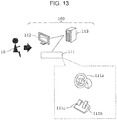
Fig. 13] Fig. 13 is a diagram illustrating a conventional remote operation apparatus. - [
Fig. 14] Fig. 14 is a graph illustrating a problem in a conventional remote operation apparatus. - [
Fig. 15] Fig. 15 is another graph illustrating a problem in a conventional remote operation apparatus. - First, underlying knowledge forming basis of the present disclosure is described below.
-
Fig. 13 is a diagram illustrating a conventional remote operation apparatus. InFig. 13 , a vehicle remote operation apparatus 100 (hereinafter, referred to as the remote operation apparatus 100) includes aremote operation unit 113, aninformation display unit 112, and anoperation input unit 111. - The
remote operation unit 113 is connected to a vehicle under control via a communication network. Theremote operation unit 113 receives, from the vehicle under control, image information representing an image around the vehicle under control, information indicating a speed of the vehicle under control, and/or the like, and theremote operation unit 113 outputs the received information to aninformation display unit 112. - The
operation input unit 111 includes asteering input unit 111a for steering the vehicle under control, anaccelerator input part 111b for changing a rotation speed of an engine of the vehicle under control, and abrake input part 111c for controlling a brake of the vehicle under control. - An
operator 10, who remotely steers the vehicle under control, operates theoperation input unit 111 based on information provided via theinformation display unit 112. A signal is generated as a result of operating theoperation input unit 111 by the operator 10 (hereinafter, this signal will be referred to as the vehicle operation signal) and is transmitted to the vehicle under control from theremote operation unit 113 via a communication network. - The vehicle under control is steered based on the received vehicle operation signal.
- In a situation in which the
operator 10 located at a remote place steers the vehicle under control using theremote operation apparatus 100, there are two problems. - A first problem is described below.
- Because the
operator 10 is not on the vehicle under control, theoperator 10 cannot directly feel a change in an increase in speed, an increase in the engine rotation speed, or the like, that occurs in the vehicle under control in response to the operation on theaccelerator input part 111b by theoperator 10. That is, theoperator 10 cannot directly feel a change occurring in the vehicle under control in response to the operation by theoperation input unit 111, which would be directly felt by a driver who is on the vehicle. Therefore, theoperator 10 cannot adjust the steering or the speed via theoperation input unit 111 in response to direct feeling of a danger or based on knowledge obtained via experiences. - In a situation in which the
operator 10 steers the vehicle under control using only the image information representing the image around the vehicle under control displayed on theinformation display unit 112 and the visual information on the speed of the vehicle under control, theoperator 10 has to carefully operate thesteering input unit 111a and theaccelerator input part 111b of theoperation input unit 111 and/or thebrake input part 111c of theaccelerator input part 111b. - However, in a case where a large and/or abrupt change occurs in the image information representing the image around the vehicle under control displayed on the
information display unit 112, theoperator 10 may focus too much on theinformation display unit 112, which may cause a reduction in concentration on the steering of the vehicle under control via theoperation input unit 111. As a result, theoperator 10 may operate theoperation input unit 111 by too great an amount, which may cause the vehicle under control to have an abrupt acceleration or deceleration, which may result in a problem in steering the vehicle under control. - A result of an experiment of steering a vehicle under control using the
remote operation apparatus 100 is described below with reference toFig. 14 andFig. 15 . More specifically, in the experiment described below, theoperator 10 operates the vehicle under control using theremote operation apparatus 100 such that the vehicle under control was first driven straight, stopped once, and then turned right. Note that in a case where turning-left was performed, a similar experimental result was obtained to that obtained when turning-right was performed. -
Fig. 14 andFig. 15 are graphs illustrating a problem in a conventional remote operation apparatus.Fig. 14 is a graph in which a steering input value and an accelerator input value in an operation of steering a vehicle under control are plotted as a function of time.Fig. 15 is a graph in which a steering input value and a speed in an operation of steering a vehicle under control are plotted as a function of time. - In
Fig. 14 , a horizontal axis represents time (seconds), a vertical axis on a left-hand side represents the steering input value (degrees), and a vertical axis on a right-hand side represents the accelerator input value. InFig. 14 , an input value 30 (a solid line in the figure) applied to thesteering input unit 111a and an input value 31 (a broken line in the figure) applied to theaccelerator input part 111b are plotted. InFig. 15 , a horizontal axis represents time (in seconds), a vertical axis on a left-hand side represents the steering input value, and a vertical axis on a right-hand side represents a speed (km/h). InFig. 15 , an input value 30 (a solid line in the figure) applied to thesteering input unit 111a and a speed 33 (a broken line in the figure) of the vehicle under control are plotted. - In
Fig. 14 andFig. 15 , in a period fromtime 110 totime 250 and in a period aftertime 410 as represented in seconds in the horizontal axis, the vehicle under control ran straight, while in a period fromtime 250 totime 410 as represented in seconds in the horizontal axis, the vehicle under control turned right. That is, theoperator 10 performed a go-straight operation on thesteering input unit 111a, and then theoperator 10 performed a stop operation on theaccelerator input part 111b and an operation on thebrake input part 111c. After that, theoperator 10 started a turn-right operation on thesteering input unit 111a. An abrupt change in the accelerator input value occurred when the turn-right operation was performed on theaccelerator input part 111b. As a result, an abrupt acceleration or deceleration was imposed on the vehicle under control unlike a situation in which the vehicle under control ran straight. - In a case where a turn-right operation is performed by a driver who is actually on a vehicle, the driver generally adjusts the speed of the vehicle depending on an acceleration or a rotation that the driver directly feels while visually watching the situation around the vehicle rather without watching a speedometer to check the vehicle speed.
- However, in the case where the
operator 10 performs an operation to turn right or turn left the vehicle under control using theremote operation apparatus 100, theoperator 10 has to operate simultaneously both thesteering input unit 111a and theaccelerator input part 111b of theoperation input unit 111 while visually checking not only the image information representing an image around the vehicle under control displayed on theinformation display unit 112 but also the vehicle speed of the vehicle under control, and thus the operation performed by theoperator 10 is difficult. - Furthermore, in a period in which the vehicle under control is turning right or left, the image information on the image around the vehicle under control displayed on the
information display unit 112 scrolls in a horizontal direction. This makes it more difficult, than in a case where the vehicle under control runs straight, for theoperator 10 to recognize the speed, the acceleration, and the rotation speed (for example, an angular velocity of the vehicle under control) of the vehicle under control. - As a result, the operation on the
accelerator input part 111b by theoperator 10 becomes rough, which causes the vehicle under control to have an abrupt acceleration or deceleration in the turning-right operation. - Next, a second problem is described below.
- When a change occurs in a condition around the vehicle under control, the
operator 10, who is not on the vehicle under control, may have a large delay in recognizing the change in the condition around the vehicle under control compared with a driver who is on a vehicle and drives the vehicle. This can cause a delay to also occur in steering the vehicle under control. - The delay can include a delay due a process of encoding an input signal provided from a camera installed on the vehicle under control, a delay due to a transmission of the encoded video information to the
remote operation unit 113 via a communication network, a delay due to a process performed by theremote operation unit 113 to decode the received image information and output the decoded image information to theinformation display unit 112, a delay due to a process performed by theremote operation unit 113 to generate a vehicle operation signal based on a result of an operation performed on theoperation input unit 111 by theoperator 10, and a delay due to a transmission of the vehicle operation signal to the vehicle under control via the communication network. That is, the delay includes a delay component due to communication depending on congestion of a network, and a delay component due to processing performed by a device or the like, and the delays change dynamically. The time period from the occurrence of a change in a condition around the vehicle under control till the operation performed on the vehicle under control is increased by an amount corresponding to the delay described above, and thus a corresponding delay occurs in the steering of the vehicle under control. - In a case where there is a large delay time from an occurrence of a change in a condition around the vehicle under control till an action in steering of the vehicle under control, when a bicycle suddenly appears in front of the vehicle under control, for example, at an intersection or a curve with poor visibility, a delay occurs in reaction of the
operator 10 at a remote location and a delay occurs in an operation on the vehicle under control to avoid a collision. - In view of the above, the present inventors have performed an investigation to find a solution to suppress an abrupt acceleration in a turn-right/left operation or the like, and the present inventors have found that the first problem described above can be solved by correcting an accelerator input value acquired during a turn-right/left operation.
- More specifically, in an aspect, the present disclosure provides a vehicle operated remotely by an operator, including a communication part that receives, in response to an operation performed by the operator, a vehicle operation signal including an accelerator input value, a steering angle sensor that measures a steering angle of the vehicle, a speed sensor that measures a speed of the vehicle, and a controller that corrects the accelerator input value such that in a case where the absolute value of the steering angle is greater than or equal to a particular angle and the speed is greater than 0, the accelerator input value is corrected so as to reduce the speed to a value smaller than when the absolute value of the steering angle is smaller than the particular angle and the speed is greater than 0.
- In this aspect, even in a situation in which the operator, who remotely operates the vehicle, cannot directly feel the acceleration or the rotation of the vehicle, a reduction in the speed of the vehicle results in a reduction in a load related to the operation of the accelerator or the brake by the operator. This makes it possible for the operator, in the remote operation of the vehicle under control, to focus on the steering operation depending on the image information representing the condition around the vehicle received from the vehicle. That is, it is possible to provide a vehicle with improved operability.
- The present inventors also have found that the second problem described above can be solved by changing the correction of the accelerator input value depending on the delay time. More specifically, the controller may further correct the accelerator input value based on a delay time from the operation by the operator to the reception of the vehicle operation signal by the communication part.
- In this aspect, it is possible to adjust the speed of the vehicle in a speed range depending on an increase or reduction in the delay time.
- Thus, even in a case where a temporary increase occurs in the delay time, the operator is allowed to operate the vehicle without being conscious of the increase in the delay time. That is, it is possible to provide a vehicle with a further improved operability.
- In the vehicle described above, the controller may correct the accelerator input value such that in a case where the absolute value of the steering angle is greater than or equal to a particular angle and the speed is greater than 0, the accelerator input value is corrected so as to quickly reduce the speed in response to an increase in the delay time.
- Furthermore, in the vehicle described above, the particular angle may also be changed based on the change in the delay time.
- In the vehicle described above, the controller may reduce the particular angle as the delay time increases.
- In an aspect, the present disclosure provides a vehicle control method for controlling a vehicle operated remotely by an operator, including the steps of, receiving, in response to an operation performed by the operator, a vehicle operation signal including an accelerator input value, and in a case where the absolute value of a steering angle of the vehicle is greater than or equal to a particular angle and a speed of the vehicle is greater than 0, correcting the accelerator input value such that the speed is reduced to a value smaller than when the absolute value of the steering angle is smaller than the particular angle and the speed is greater than 0.
- In an aspect, the present disclosure provides a vehicle remote operation apparatus used by an operator to remotely operate a vehicle, including an accelerator input part that outputs an accelerator input value in accordance with an operation performed by the operator to control a speed of the vehicle, a communication part that receives the speed of the vehicle, and a controller that corrects the accelerator input value such that in a case where the absolute value of a steering angle of the vehicle is greater than or equal to a particular angle and the speed is greater than 0, the accelerator input value is corrected so as to reduce the speed to a value smaller than when the absolute value of the steering angle is smaller than the particular angle and the speed is greater than 0.
- In an aspect, the present disclosure provides a vehicle remote operation method for remotely operating a vehicle by an operator, including the steps of acquiring an accelerator input value, which controls a speed of the vehicle, in accordance with an operation performed by the operator, receiving the speed of the vehicle, and correcting the accelerator input value such that in a case where the absolute value of a steering angle of the vehicle is greater than or equal to a particular angle and the speed is greater than 0, the accelerator input value is corrected so as to reduce the speed to a value smaller than when the absolute value of the steering angle is smaller than the particular angle and the speed is greater than 0.
- General or specific embodiments may be implemented as a system, a method, an integrated circuit, a computer program, a computer-readable non-temporary record medium such as a CD-ROM disk, or any selective combination of a system, a method, an integrated circuit, a computer program, and a storage medium. The program may be stored in advance in a storage medium or may be supplied to a storage medium via a wide area network including the Internet or the like.
- Embodiments are described in detail below with reference to drawings.
- Note that any embodiment described below is provided to illustrate a general or specific example. In the following embodiments, values, shapes, materials, constituent elements, locations of elements, manners of connecting elements, steps, the order of steps, and the like are described by way of example but not limitation. Among constituent elements described in the following embodiments, those constituent elements that are not described in independent claims indicating highest-level concepts of the present disclosure are optional. Note that each drawing is a schematic diagram, which does not necessarily provide a strict description.
-
Fig. 1 is a diagram illustrating an example of a remote operation system according to a first embodiment. In aremote operation system 1000, anoperator 10 steers avehicle 16 under control from a remote place. Thevehicle 16 under control is connected to a vehicle remote operation apparatus 200 (hereinafter, referred to as a remote operation apparatus 200) via aradio base station 15 such as a wireless LAN, a portable telephone, or the like and anetwork 14. Theremote operation apparatus 200 includes aremote operation unit 13, aninformation display unit 12, and anoperation input unit 11 for steering thevehicle 16 under control. Note that theremote operation apparatus 200 may include not only a singleinformation display unit 12 but a plurality ofinformation display units 12. Note that thevehicle 16 under control is an example of a vehicle remotely operated by theoperator 10. - The
remote operation unit 13 outputs, to theinformation display unit 12, video information representing an image around thevehicle 16 under control and a speed of thevehicle 16 under control, transmitted from thevehicle 16 under control. Theoperation input unit 11 includes at least asteering input unit 11a for controlling the steering of thevehicle 16 under control, anaccelerator input part 11b for controlling the rotation speed of an engine or a motor of thevehicle 16 under control, and abrake input part 11c for controlling a brake of thevehicle 16 under control. The speed of thevehicle 16 under control is controlled by theaccelerator input part 11b and thebrake input part 11c. For example, thesteering input unit 11a is a steering wheel, theaccelerator input part 11b is an accelerator pedal, and thebrake input part 11c is a brake pedal. - The
steering input unit 11a outputs, in response to an operation performed by theoperator 10, a steering input value for controlling the steering of thevehicle 16 under control to a vehicle operationsignal generation unit 1303. Theaccelerator input part 11b outputs, in response to an operation performed by theoperator 10, an accelerator input value for controlling the speed of thevehicle 16 under control to the vehicle operationsignal generation unit 1303. - In
Fig. 1 , theaccelerator input part 11b or thebrake input part 11c is of a pedal type that is operated by theoperator 10 with his/her foot. However, the type thereof is not limited to this example. For example, theaccelerator input part 11b or thebrake input part 11c may be of a lever type that is operated by theoperator 10 with his/her hand. Alternatively, theaccelerator input part 11b or thebrake input part 11c may be of a type in which a target speed is input. Thesteering input unit 11a is a steering wheel that is operated by theoperator 10 with his/her hands. However, thesteering input unit 11a is not limited to this type. For example, thesteering input unit 11a may be of a type in which a target steering angle is input. - The
operator 10, who remotely steers thevehicle 16 under control, operates theoperation input unit 11 based on information provided via theinformation display unit 12. A signal is generated as a result of operating theoperation input unit 11 by theoperator 10, and the resultant signal is transmitted as the vehicle operation signal to thevehicle 16 under control from theremote operation unit 13 via thenetwork 14 and theradio base station 15. Thevehicle 16 under control is steered based on the received vehicle operation signal. - The vehicle operation signal includes at least an accelerator input value which is a signal generated when the
operator 10 operates theaccelerator input part 11b or thebrake input part 11c. The vehicle operation signal may further include a steering input value which is a signal generated when theoperator 10 operates thesteering input unit 11a. The vehicle operation signal may include information indicating a time at which theoperation input unit 11 is operated by theoperator 10. - A configuration of the
vehicle 16 under control is described below with reference toFig. 2 . -
Fig. 2 is a block diagram illustrating an example of a configuration of thevehicle 16 under control in theremote operation system 1000 according to the present embodiment. InFig. 2 , thevehicle 16 under control includes at least awireless communication unit 1601, a steering angle sensor 1602, aspeed sensor 1603, aspeed control unit 1604, asteering control unit 1605, in-vehicle networks remote control unit 1608, and one ormore cameras 1609. Note thatFig. 2 illustrates an example of a configuration of elements, in thevehicle 16 under control, relating to the remote operation. - The
wireless communication unit 1601 wirelessly communicates with theradio base station 15. Note that thewireless communication unit 1601 is a radio communication module that receives a vehicle operation signal including at least an accelerator input value, and thiswireless communication unit 1601 is an example of a communication part. - The steering angle sensor 1602 measures a steering angle of the
vehicle 16 under control and outputs information associated with the steering angle over the in-vehicle network 1607. - The
speed sensor 1603 measures a speed of thevehicle 16 under control and outputs information associated with the speed over the in-vehicle network 1607. - The
speed control unit 1604 controls the speed by operating the accelerator, the brake, and the drive shift of thevehicle 16 under control. - The
steering control unit 1605 controls a running direction of the vehicle by performing a steering operation on thevehicle 16 under control. - The in-
vehicle networks vehicle 16 under control. That is, the sensors and the units installed on thevehicle 16 under control are connected to each other via the in-vehicle networks vehicle networks - The one or
more cameras 1609 are disposed such that an image can be captured from thevehicle 16 under control at least in one of directions including a forward direction (for example, a running direction), a backward direction, a leftward direction, and a rightward direction, thereby acquiring an image around thevehicle 16 under control. - The
remote control unit 1608 acquires information output from the steering angle sensor 1602 and thespeed sensor 1603 via the in-vehicle network 1607. - The
remote control unit 1608 generates image information representing images in the forward, backward, leftward, and rightward directions seen from thevehicle 16 under control, based on information provided by the one ormore cameras 1609. Theremote control unit 1608 then transmits the generated image information to theremote operation apparatus 200 via thewireless communication unit 1601. - The
remote control unit 1608 receives the vehicle operation signal transmitted from theremote operation apparatus 200 via thewireless communication unit 1601. - Based on the received vehicle operation signal, the
remote control unit 1608 controls running of thevehicle 16 under control via thespeed control unit 1604 and thesteering control unit 1605. In this process, theremote control unit 1608 corrects the accelerator input value included in the vehicle operation signal received from theremote operation apparatus 200 based on, at least, the vehicle information of thevehicle 16 under control acquired from the steering angle sensor 1602 and thespeed sensor 1603, and theremote control unit 1608 outputs the resultant corrected accelerator input value to thespeed control unit 1604. Note that theremote control unit 1608 is a control apparatus installed on thevehicle 16 under control and is an example of a controller that corrects the accelerator input value. - Next, a configuration of the
remote operation unit 13 of theremote operation apparatus 200 is described below with reference toFig. 3 . -
Fig. 3 is a block diagram illustrating an example of a configuration of theremote operation unit 13 of theremote operation apparatus 200 in theremote operation system 1000 according to the present embodiment. InFig. 3 , theremote operation unit 13 includes, at least, acommunication interface 1301, a vehicle operationsignal transmission unit 1302, a vehicle operationsignal generation unit 1303, a vehicleinformation reception unit 1304, an HMI (Human Machine Interface)generation unit 1305, and an imageinformation reception unit 1306. - The
communication interface 1301 is connected to thenetwork 14 and communicates with thevehicle 16 under control. Note that thewireless communication unit 1601 is a radio communication module for communicating with thevehicle 16 under control and is an example of a communication part included in theremote operation apparatus 200. - The vehicle operation
signal generation unit 1303 generates a vehicle operation signal based on an operation performed on theoperation input unit 11 by theoperator 10. - The vehicle operation
signal transmission unit 1302 transmits the vehicle operation signal generated by the vehicle operationsignal generation unit 1303 to thevehicle 16 under control via thecommunication interface 1301. - The vehicle
information reception unit 1304 receives at least the vehicle information transmitted by thevehicle 16 under control via thecommunication interface 1301. - The image
information reception unit 1306 receives the image information transmitted by thevehicle 16 under control via thecommunication interface 1301. - Based on the received vehicle information and image information, the
HMI generation unit 1305 generates information necessary in the operation of thevehicle 16 under control by theoperator 10, and theHMI generation unit 1305 outputs the generated information to theinformation display unit 12. - Next, an operation (a process) in the
vehicle 16 under control is described below with reference toFig. 4 . -
Fig. 4 is a flow chart illustrating an example of a process, performed in theremote control unit 1608, on the vehicle operation signal received from theremote operation apparatus 200 according to the present embodiment. - The
remote control unit 1608 performs the process described in the flow chart inFig. 4 repeatedly as long as the operation on theremote operation apparatus 200 by theoperator 10 continues. - In
Fig. 4 , in a case where theremote control unit 1608 receives a vehicle operation signal from theremote operation unit 13 of theremote operation apparatus 200 or in a case where a fixed time has elapsed since a previous reception of a vehicle operation signal (in a case where YES in S10), theremote control unit 1608 acquires a steering angle of thevehicle 16 under control from the steering angle sensor 1602 and acquires a speed of thevehicle 16 under control from the speed sensor 1603 (S11). Note that there is no particular restriction on the fixed time. For example, the fixed time may be 500 ms, 1 s, or the like. In a case where in step S10, the fixed time has elapsed from a previous reception of a vehicle operation signal, theremote control unit 1608 performs a process described below using the previously received vehicle operation signal. Note that also this case is regarded as a case in which a vehicle operation signal has been received. Also note that step S10 is an example of a step of receiving a vehicle operation signal. - On the other hand, in a case where the
remote control unit 1608 has not received a vehicle operation signal from theremote operation unit 13 of theremote operation apparatus 200, or in a case where the fixed time has not yet elapsed since the previous reception of a vehicle operation signal (in a case where NO in step S10), the processing flow returns to step S10. - Next, the
remote control unit 1608 corrects the accelerator input value included in the vehicle operation signal received in step S10 or the accelerator input value included in the previously received vehicle operation signal, based on the steering angle and the speed acquired in step S11 (step S12). Note that step S12 is an example of a step of correcting the accelerator input value. - The
remote control unit 1608 inputs the resultant corrected accelerator input value to the speed control unit 1604 (step S13). - Next, a process of correcting the accelerator input value in step S12 is described below with reference to
Fig. 5 to Fig. 8 . The present embodiment has a feature that the correction of the accelerator input value or the like included in the vehicle operation signal received in step S10 is performed differently depending on the steering angle and the speed acquired in step S11. Theremote control unit 1608 performs the correction, for example, such that when theoperator 10 remotely operates thevehicle 16 under control in a situation in which theoperator 10 is not on thevehicle 16 under control and thus theoperator 10 cannot get information via feeling which would be obtained on site, the correction allows theoperator 10 to drive thevehicle 16 under control in a safer manner. -
Fig. 5 is a flow chart illustrating an example of a correction process on the accelerator input value included in the vehicle operation signal. More specifically, the flow chart inFig. 5 illustrates an example of a correction process, performed in step S12 inFig. 4 , on the accelerator input value included in the vehicle operation signal. - In
Fig. 5 , in a case where the absolute value of the steering angle acquired in step S11 is greater than or equal to a steering angle threshold value θ (in a case where YES in S20), theremote control unit 1608 proceeds to step S21. - On the other hand, in a case where the absolute value of the steering angle acquired in step S11 is smaller than the steering angle threshold value θ (in a case where NO in S20), the
remote control unit 1608 executes a correction factor calculation process 3 (S24). The correctionfactor calculation process 3 is executed by theremote control unit 1608, for example, when thevehicle 16 under control is moving straight. - In a case where the speed is greater than 0 (in a case where YES in S21), the
remote control unit 1608 executes a correction factor calculation process 1(S22). The correctionfactor calculation process 1 is executed by theremote control unit 1608, for example, when thevehicle 16 under control is turning right or left. On the other hand, in a case where the speed is equal to 0 (in a case where NO in S21), theremote control unit 1608 executes a correction factor calculation process 2(S23). The correctionfactor calculation process 2 is executed by theremote control unit 1608, for example, when the steering wheel is turned and thevehicle 16 under control is started from a state in which thevehicle 16 under control is stopped. - The
remote control unit 1608 then corrects the accelerator input value included in the vehicle operation signal based on a result of the process in one of steps S22 to S24 (S25). - Next, the correction factor calculation process in steps S22 to S24 is described below. First, a process of calculating a corrected accelerator input value from an accelerator input value included in a received vehicle operation signal is described.
Formula 1 shows an example of a formula used in step S25 to correct the accelerator input value included in the vehicle operation signal. Informula 1, AC_IN denotes the accelerator input value included in the vehicle operation signal, and AC_OUT denotes a corrected accelerator input value. C denotes a correction factor, and C_MAX denotes a maximum value of the correction factor C. The correction factor C is a factor used, for example, to convert the received accelerator input value to a speed of thevehicle 16 under control. The correction factor C is a variable that is changed via processes described below with reference toFig. 6 to Fig. 8 . The maximum value C_MAX has a predetermined value. The maximum value C_MAX is a fixed value equal to, for example, "10", "100", or the like.
[Math. 1]
- For example, in a case where the correction factor C is equal to the maximum value C_MAX, the accelerator input value AC_IN is equal to the corrected accelerator input value AC_OUT as can be seen from
formula 1. In a case where the correction factor C is smaller than the maximum value C_MAX, the corrected accelerator input value AC_OUT is smaller than the accelerator input value AC_IN. In this case, the speed of thevehicle 16 under control is smaller than a value at which the speed would be controlled by the accelerator input value AC_IN. The correction factor C is further described below with reference toFig. 6 to Fig. 8 . -
Fig. 6 is a flow chart illustrating an example of the correctionfactor calculation process 1. When theoperator 10 is performing an operation of turning thevehicle 16 under control right or left or a similar operation, the image on theinformation display unit 12 viewed by theoperator 10 scrolls horizontally, which makes it difficult for theoperator 10 to perceive a correct distance to an object on the image. Besides, as described above, because theoperator 10 is not on thevehicle 16 under control, theoperator 10 cannot get information which would be otherwise obtained via feeling on site. Therefore, when theoperator 10 is performing an operation of turning thevehicle 16 under control right or left or a similar operation, it is difficult for theoperator 10 to finely control the accelerator. For example, there is a possibility that theoperator 10 presses theaccelerator input part 11b too much and thus thevehicle 16 under control has an abrupt acceleration during the turning-right/left operation (seeFig. 14 andFig. 15 ). To handle the above situation, in the correctionfactor calculation process 1 in step S22, the accelerator input value is corrected so as to reduce the probability of an occurrence of an abrupt acceleration on thevehicle 16 under control. More specifically, in the correctionfactor calculation process 1, a process is executed to reduce the correction factor C. Note that a limiting factor K is a factor that varies depending on the delay time described above. The limiting factor K is set, for example, such that when the delay time is equal to a minimum value or smaller than or equal to a particular value, the limiting factor K is set to "1", and the limiting factor K is increased as the delay time increases. Theremote control unit 1608 may have a table stored therein which describes, for example, a correspondence between the delay time and the limiting factor K, whereby the limiting factor K may be set from the delay time using the table. However, in the following description of step S22, it is assumed by way of example that the limiting factor K is constant (that is, the delay time is constant). - As shown in
Fig. 6 , in a case where the correction factor C is greater than C_MAX/K (in a case where YES in S30), theremote control unit 1608 subtracts 1 from the correction factor C and employs a result as a new value of the correction factor C (S31). The execution of the correctionfactor calculation process 1 causes the correction factor C to be changed to a value smaller than the original uncorrected value. For example, the correctionfactor calculation process 1 is performed repeatedly until the correction factor C becomes equal to C_MAX/K. Hereinafter, the value used in the correction factor calculation processes 1 to 3 will also be referred as a reference value. In the present embodiment, a value given by C_MAX/K is the reference value. This holds also in the following description explained with reference toFig. 7 and other figures. - In the process in step S31 described above, "1" is subtracted from the correction factor C. However, the value subtracted from the correction factor C is not limited to "1" as long as the corrected correction factor C obtained as a result of the correction
factor calculation process 1 in step S31 is smaller than the original value of the correction factor C before being subjected to the correctionfactor calculation process 1. For example, in the correctionfactor calculation process 1 in step S31, the original value of the correction factor C may be multiplied by a value smaller than "1", thereby correcting the correction factor C. - On the other hand, in a case where the correction factor C is smaller than or equal to the reference value (in a case where NO in S30), the
remote control unit 1608 ends the process without performing anything. That is, the original value, which the correction factor C has before the correctionfactor calculation process 1 is executed, is maintained. - As described above, after the correction
factor calculation process 1 is executed, the correction factor C becomes smaller than or equal to the reference value. As a result, the accelerator input value AC_OUT obtained as a result of the correction according toformula 1 is smaller than the accelerator input value AC_IN. Thus, even in a case where theoperator 10 presses theaccelerator input part 11b too much, thevehicle 16 under control is prevented from being abruptly accelerated. That is, when the speed of thevehicle 16 under control changes abruptly, the change is slowed down. The process in step S22 is performed to limit the change in the speed of thevehicle 16 under control in a situation in which it is difficult for theoperator 10 to finely control the operation on the accelerator. Thus, even in a case where theoperator 10 presses theaccelerator input part 11b too much during a turning-right/left operation, thevehicle 16 under control is turned right/left smoothly. -
Fig. 7 is a flow chart illustrating the correctionfactor calculation process 2. When theoperator 10 starts thevehicle 16 under control from a state in which thevehicle 16 under control is stopped and turns thevehicle 16 under control to the right/left, theoperator 10 operates theoperation input unit 11 while watching an image displayed on theinformation display unit 12. When the delay time is large, there can be a possibility that the image displayed on theinformation display unit 12 does not represent an actual situation around thevehicle 16 under control. However, in the case where there is a large delay time, theoperator 10 operates theoperation input unit 11 based on the image displayed information display unit 12 (based on the image representing, for example, a situation which occurred a little while ago, but it is difficult for theoperator 10 to take into account the delay during the operation. That is, when there is a large delay time, it may be difficult for theoperator 10 to properly start thevehicle 16 under control. To handle the above situation, in the correctionfactor calculation process 2, a process is executed to correct the accelerator input value depending on the delay time such that it becomes possible to properly start thevehicle 16 under control even when the delay time is large. - As shown in
Fig. 7 , theremote control unit 1608 sets the correction factor C to be equal to the reference value (C_MAX/K) (S40). The limiting factor K is increased as the delay time increases, and thus the reference value decreases as the delay time increases. For example, when the delay time is large, the correction factor C is set to a value smaller than in a case where the delay time is small. On the other hand, the limiting factor decreases as the delay time decrease, and thus the reference value decreases as the delay time increases. For example, when the delay time is large, the correction factor C is set to a value greater than in a case where the delay time is small. That is, in the correctionfactor calculation process 2, when thevehicle 16 under control in the stopped state is started, the initial value of the correction factor C is set depending on the delay time. For example, in a case where the limiting factor K is equal to 2, the correction factor C is set to be equal to one-half the maximum value C_MAX. - After the
vehicle 16 under control is started, the processes in step S22 and S24 are executed using the correction factor C set in step S23. -
Fig. 8 is a flow chart illustrating the correctionfactor calculation process 3. When thevehicle 16 under control is running straight, theoperator 10 can perform the operation on the accelerator more finely than when thevehicle 16 under control is turning right/left. In view of the above, in the correctionfactor calculation process 3, a process is executed to make a correction such that the corrected value given as the accelerator input value AC_OUT becomes close to the accelerator input value AC_IN. That is, the process is performed such that the accelerator input value AC_IN is more directly reflected on the speed of thevehicle 16 under control. More specifically, in the correctionfactor calculation process 3, the process is performed such that the correction factor C is increased. - As shown in
Fig. 8 , in a case where the correction factor C is smaller than the reference value (C_MAX/K) (in a case where YES in S50), theremote control unit 1608 adds 1 to the correction factor C and employs a resultant value as a new value of the correction factor C (S51). In a case where the correction factor C is smaller than the correction factor C, the correction factor C is changed by executing the correctionfactor calculation process 3 such that the corrected value is greater than the original uncorrected value. For example, the correctionfactor calculation process 3 is performed repeatedly until the correction factor C becomes equal to the reference value. That is, the correction factor C increases such that the corrected value given as the accelerator input value AC_OUT becomes close to the accelerator input value AC_IN. - In the process in step S51 described above, "1" is added to the correction factor C. However, the value added to the correction factor C is not limited to "1" as long as the corrected correction factor C obtained as a result of the correction
factor calculation process 3 in step S51 is greater than the original value that the correction factor C has before the correctionfactor calculation process 3 is executed. For example, in the correctionfactor calculation process 3 in step S51, the original value of the correction factor C may be multiplied by a value greater than "1", thereby correcting the correction factor C. - On the other hand, in a case where the correction factor C is greater than or equal to the reference value (in a case where NO in S50), the
remote control unit 1608 sets the correction factor C to be equal to the reference value (S52). The process in step S52 may be performed in many ways as long as the correction factor C greater than or equal to the reference value is reduced. The process in step S52 may be performed such that 1 is subtracted from the correction factor C. The result of the determination in step S50 can be NO, for example, in a case where when the vehicle is running straight, the delay time increases and accordingly the limiting factor K increases. - As described above, the correction factor C obtained after the correction
factor calculation process 3 is executed, the correction factor C becomes greater than or equal to the reference value. Thus, the corrected value given as the accelerator input value AC_OUT according toformula 1 becomes closer to the value of the accelerator input value AC_IN than in the case where correctionfactor calculation process 1 is executed, and thus, a result of an operation on theaccelerator input part 11b by theoperator 10 can be more directly reflected on the speed of thevehicle 16 under control. The process in step S24 is performed such that in a situation in which it is easy for theoperator 10 perform a fine operation on the accelerator, the restriction on the change in the speed of thevehicle 16 under control is loosened. This makes it possible for thevehicle 16 under control to run at a speed close to a value intended by theoperator 10. - As described above, according to the present embodiment, the
vehicle 16 under control includes theremote control unit 1608 that corrects the accelerator input value such that in a case where the absolute value of the steering angle measured by the steering angle sensor 1602 is greater than or equal to the steering angle threshold value θ and the measured speed, which is a speed measured by thespeed sensor 1603, is greater than 0 (YES in S20 and S21), the accelerator input value is corrected so as to reduce the speed of thevehicle 16 under control controlled by the accelerator input value to a value lower than in a case where the absolute value of the steering angle is smaller than the steeringangle threshold value 0 and the measured speed is greater than 0 (NO in S20). - Via the procedure described above, when the
operator 10 controls the running of thevehicle 16 under control by operating theaccelerator input part 11b while operating thesteering input unit 11a, theremote control unit 1608 of thevehicle 16 under control corrects the accelerator input value included in the vehicle operation signal received from theremote operation apparatus 200, and inputs (outputs) the resultant corrected accelerator input value to thespeed control unit 1604. Thus, in a situation in which theoperator 10 performs operations simultaneously on both thesteering input unit 11a and theaccelerator input part 11b, even when an operation performed on theaccelerator input part 11b is excessive, thevehicle 16 under control is turned while its speed is gradually increased without being abruptly accelerated. That is, it possible to realize a vehicle with improved operability and a method for controlling the vehicle. - Note that in the process of correcting the accelerator input value included in the vehicle operation signal in step S12 in
Fig. 4 , theremote control unit 1608 may calculate a delay time, associated with a network including theradio base station 15, between theremote operation apparatus 200 and thevehicle 16 under control, and theremote control unit 1608 may correct the accelerator input value included in the vehicle operation signal taking into account the calculated delay time. That is, theremote control unit 1608 may correct the accelerator input value further taking into account the delay time from the operation by theoperator 10 to the reception of the vehicle operation signal by thewireless communication unit 1601. - More specifically, the
remote control unit 1608 sets the limiting factor K to be variable from 1 to the maximum value C_MAX, inclusive, and increases the limiting factor K up to C_MAX depending on an increase in the delay time. When the condition for executing the correction factor calculation process 1 (S22) is satisfied, the correction factor C is substituted by a value smaller than a value that the correction factor C has before an occurrence of an increase in the delay. As a result, a reduction occurs in the corrected value given by the accelerator input value AC_OUT calculated according toformula 1. Therefore, thevehicle 16 under control is capable of quickly reducing the speed. That is, theremote control unit 1608 may correct the accelerator input value such that the speed of thevehicle 16 under control is quickly reduced as the delay time increases. - In a case where the limiting factor K has a large value and the condition for executing the correction factor calculation process 2 (S23) or the correction factor calculation process 3 (S24) is satisfied, the correction factor C is limited to smaller values than in a case where the limiting factor is smaller, which causes a reduction to occur in the corrected value given by the accelerator input value AC_OUT calculated according to
formula 1. As a result, thevehicle 16 under control is capable of more slowly increasing the speed. - On the other hand, the
remote control unit 1608 reduces the limiting factor K down to 1 depending on a reduction in the delay time. In this case, when the condition for executing the correction factor calculation process 1 (S22) is satisfied, the correction factor C is substituted by a greater value than in a case where the delay time is great, and thus an increase occurs in the corrected value given by the accelerator input value AC_OUT calculated according toformula 1. Therefore, thevehicle 16 under control is capable of slowly reducing the speed compared with a case where the delay time is large. - In a case where the limiting factor K has a small value and the condition for executing the correction factor calculation process 2 (S23) or the correction factor calculation process 3 (S24) is satisfied, the correction factor C is limited to greater values than in a case where the limiting factor is greater, which causes an increase to occur in the corrected value given by the accelerator input value AC_OUT calculated according to
formula 1. As a result, thevehicle 16 under control is capable of more quickly increasing the speed. - It is difficult for the
operator 10 to operate theoperation input unit 11 depending on the delay time. When the reference value includes the limiting factor K and thus the reference value changes dynamically, the accelerator input value AC_IN is properly corrected depending on the delay time, and thus it is possible to realize a vehicle with further improved operability and a method for controlling the vehicle. - In an alternative example, depending on an increase or reduction in the delay time, the
remote control unit 1608 may reduce or increase the steering angle threshold value θ based on which the determination is made in step S20 inFig. 5 as to whether the steering angle is greater than or equal to the particular value. That is, theremote control unit 1608 may change the steering angle threshold value θ (an example of a particular angle) based on the delay time. More specifically, theremote control unit 1608 may change the steering angle threshold value θ based on a change in the delay time. An operation performed by theremote control unit 1608 to change the steering angle threshold value θ is described below with reference toFig. 9 . -
Fig. 9 is a flow chart illustrating an example of a process of changing the steering angle threshold value θ. - As shown in
Fig. 9 , theremote control unit 1608 determines whether an increase in the delay time has occurred (S60). For example, theremote control unit 1608 determines whether a delay time calculated from a current time and information included in the received vehicle operation signal and indicating a time at which theoperation input unit 11 was operated by theoperator 10 is greater than a delay time calculated from a vehicle operation signal acquired in a previous reception. In a case where it is determined that an increase in the delay time has occurred (YES in S60), theremote control unit 1608 reduces the steering angle threshold value θ (S61). That is, theremote control unit 1608 reduces the steering angle threshold value θ as the delay time increases. As a result, for example, when an increase in the delay time occurs, the processing flow proceeds to step S22 even when the steering angle is smaller in order to perform a process of limiting the change in the speed of thevehicle 16 under control. That is, in a case where an increase in the delay time occurs, the correction of the accelerator input value is performed for a range of the steering angle whose lower limit is reduced. - On the other hand, in a case where it is determined that no increase in the delay time has occurred (NO in S60), the
remote control unit 1608 determines whether a reduction in the delay time has occurred (S62). In a case where it is determined that a reduction in the delay time has occurred (YES in S62), theremote control unit 1608 increases the steering angle threshold value θ (S63). On the other hand, in a case where it is determined that no reduction in the delay time has occurred (NO in S62), that is, in a case where no change in the delay time has occurred, theremote control unit 1608 ends the process without changing the steering angle threshold value θ. Note that in a case where a difference between a delay time calculated from a latest vehicle control signal and a delay time calculated from a previously acquired vehicle operation signal is greater than or equal to a particular value, theremote control unit 1608 may determine affirmatively in step S60 or S62. - Note that the manner of changing the steering angle threshold value θ is not limited to the example described above. For example, when the delay time becomes greater than a particular threshold value, the
remote control unit 1608 may change the steering angle threshold value θ to a smaller value. - Note that in the determination in step S21 in
Fig. 5 , "acceleration" may be judged instead of the "speed". - Note that the delay time described above may further include one or more of the following delays: a delay due to encoding an input signal provided by the
camera 1609 installed on thevehicle 16 under control; a delay from a time at which theremote operation apparatus 200 receives and encodes image information to a time at which a resultant image information is output to theinformation display unit 12; and a delay due to a process performed by theremote operation unit 13 to generate a vehicle operation signal based on a result of an operation on theoperation input unit 11 by theoperator 10. - In steps S22 to S24 (the correction
factor calculation process 1 to the correction factor calculation process 3) described above, by way of example, the limiting factor K is used in the calculation of the reference value. However, the manner of calculating the reference value is not limited to the example described above. At least one of steps S22 to S24, the reference value may be calculated without using the limiting factor K. In the above description, it is assumed by way of example that the reference value is equal for all steps S22 to S24. However, the reference value is not limited to this example. The reference value may be different among the steps S22 to S24. For example, the reference value used in step S22 may be set to a value smaller than a value of the reference value used in step S24. - As described above, in the present embodiment, the
vehicle 16 under control remotely operated by theoperator 10 includes the wireless communication unit 1601 (an example of a communication part) that receives, in response to an operation performed by the operator, the vehicle operation signal including the accelerator input value, the steering angle sensor 1602 that measures the steering angle of thevehicle 16 under control, thespeed sensor 1603 that measures the speed of thevehicle 16 under control, and the remote control unit 1608 (an example of a controller) that corrects the accelerator input value such that in a case where the absolute value of the steering angle is greater than or equal to the particular angle and the speed is greater than 0, the accelerator input value is corrected so as to reduce the speed to a value smaller than when the absolute value of the steering angle is smaller than the particular angle and the speed is greater than 0. - Thus, in this
vehicle 16 under control operated by theoperator 10, even in a situation in which theoperator 10 cannot directly feel the acceleration, the rotation, or the like of thevehicle 16 under control, the speed of thevehicle 16 under control is reduced to a value smaller than is directly controlled by the accelerator input value, and thus thevehicle 16 under control is prevented from being abruptly accelerated. Furthermore, it is possible to reduce a load related to the operation of theaccelerator input part 11b and thebrake input part 11c. That is, when theoperator 10 remotely operates thevehicle 16 under control, theoperator 10 is allowed to concentrate on the operation of thesteering input unit 11a according to an image around the vehicle transmitted from thevehicle 16 under control. That is, it is possible to provide a vehicle with further improved operability. - Furthermore, the
remote control unit 1608 corrects the accelerator input value taking into account also the delay time from the operation of theoperator 10 to the reception of the vehicle operation signal by thewireless communication unit 1601. - This makes it possible for the
remote control unit 1608 to adjust the speed of thevehicle 16 under control to a value depending on an increase/decrease in the delay time. Therefore, even when a temporary increase in the delay time occurs, theoperator 10 is allowed to operate thevehicle 16 under control without being conscious of the increase in the delay time. Thus, it is possible to provide avehicle 16 under control with a further improved operability. - Furthermore, in a case where the absolute value of the steering angle is greater than or equal to a steering angle threshold value θ and the speed is greater than 0, the
remote control unit 1608 corrects the accelerator input value such that the speed of thevehicle 16 under control is quickly reduced as the delay time increases. - Therefore, even in a situation in which it is difficult for the
operator 10 to operate thevehicle 16 under control taking into account the delay time, theremote control unit 1608 is capable of adjusting the speed of thevehicle 16 under control such that the speed decreases as the delay time increases. Thus, it is possible to provide avehicle 16 under control with a further improved operability. - Furthermore, the
remote control unit 1608 changes the steering angle threshold value θ based on a change in the delay time. - This makes it possible for the
remote control unit 1608 to control the speed of thevehicle 16 under control based on the steering angle threshold value θ depending on an increase/decrease in the delay time. Therefore, even when a temporary increase in the delay time occurs, theoperator 10 is allowed to operate thevehicle 16 under control without being conscious of the increase in the delay time. Thus, it is possible to provide avehicle 16 under control with a further improved operability. - Furthermore, the
remote control unit 1608 reduces the steering angle threshold value θ as the delay time increases. - This makes it possible for the
remote control unit 1608 limit the speed of thevehicle 16 under control for a range of the steering angle whose lower limit is reduced as the delay time increases. Thus, it is possible to provide avehicle 16 under control with further improved operability. - As described above, according to the present embodiment, the vehicle control method for controlling the
vehicle 16 under control remotely operated by theoperator 10 includes receiving, in response to an operation performed by theoperator 10, a vehicle operation signal including an accelerator input value (S10), and correcting the accelerator input value such that in a case where the absolute value of the steering angle of thevehicle 16 under control is greater than or equal to the particular angle and the speed of thevehicle 16 under control is greater than 0, the accelerator input value is corrected so as to reduce the speed to a value smaller than when the absolute value of the steering angle is smaller than the particular angle and the speed is greater than 0 (S12). - This provides advantageous effects similar to those provided by the
vehicle 16 under control described above. - Next, a second embodiment is described below. In the first embodiment, the vehicle under
control 16 corrects the accelerator input value included in the vehicle operation signal generated by theremote operation apparatus 200 and received by the vehicle undercontrol 16. The second embodiment is different in that an accelerator input value is corrected by theremote operation apparatus 200 based on vehicle information associated with thevehicle 16 under control, and then a vehicle operation signal is generated. - The second embodiment is described below while focusing on differences from the first embodiment.
- A remote operation system according to the second embodiment is the same as the
remote operation system 1000 according to the first embodiment, and thus a description thereof is omitted. - A detailed configuration associated with the remote operation of the
vehicle 16 under control according to the second embodiment is basically similar to that of thevehicle 16 under control according to the first embodiment. A description is given below focusing on differences from the first embodiment. - The
remote control unit 1608 acquires the steering angle output from the steering angle sensor 1602 and the speed output from thespeed sensor 1603, and transmits them as vehicle information to theremote operation apparatus 200 via thewireless communication unit 1601. - In the first embodiment, the
remote control unit 1608 corrects the accelerator input value included in the vehicle operation signal received from theremote operation apparatus 200. In the second embodiment, theremote control unit 1608 does not perform the correction on the accelerator input value included in the vehicle operation signal received from theremote operation apparatus 200. -
Fig. 10 is a diagram illustrating an example of a configuration of aremote operation unit 13a in the remote operation system according to the present embodiment. The configuration is described below while focusing on differences from the first embodiment. InFig. 10 , theremote operation unit 13a includes a vehicleinformation storage unit 1307 in addition to the elements included in theremote operation unit 13 according to the first embodiment. - The vehicle
information reception unit 1304 receives at least vehicle information transmitted by thevehicle 16 under control via thecommunication interface 1301. The vehicleinformation reception unit 1304 is an example of a communication part that receives vehicle information including information indicating the speed of thevehicle 16 under control. - The vehicle
information reception unit 1304 outputs the received vehicle information to theHMI generation unit 1305 and stores the received vehicle information in the vehicleinformation storage unit 1307. - The vehicle
information storage unit 1307 stores the vehicle information received by the vehicleinformation reception unit 1304. The vehicleinformation storage unit 1307 is a storage apparatus such as a semiconductor memory or the like. - The vehicle operation
signal generation unit 1303 generates a vehicle operation signal based on an operation performed on theoperation input unit 11 by theoperator 10. - The vehicle operation
signal generation unit 1303 makes a correction, based on the vehicle information associated with thevehicle 16 under control stored in the vehicleinformation storage unit 1307, on an accelerator input value which is a signal generated as a result of operating theaccelerator input part 11b of theoperation input unit 11 by theoperator 10 and which is included in the vehicle operation signal to be transmitted to thevehicle 16 under control. That is, the vehicle operationsignal generation unit 1303 makes the correction, based on the vehicle information associated with thevehicle 16 under control stored in the vehicleinformation storage unit 1307, on the accelerator input value which is the signal generated as a result of operating theaccelerator input part 11b of theoperation input unit 11 by theoperator 10 thereby generating the vehicle operation signal. Note that the vehicle information associated with thevehicle 16 under control is information including the steering angle of thevehicle 16 under control acquired from the steering angle sensor 1602 and the speed of thevehicle 16 under control acquired from thespeed sensor 1603. The vehicle operationsignal generation unit 1303 is a controller included in theremote operation apparatus 200 and is an example of a controller that corrects the accelerator input value. - Thus, in the
vehicle 16 under control operated by theoperator 10, configured in the above-described manner, even in a situation in which theoperator 10 cannot directly feel the acceleration, the rotation, or the like of thevehicle 16 under control, the accelerator input value which is the signal generated as a result of operating theaccelerator input part 11b by theoperator 10 is corrected based on the vehicle information associated with thevehicle 16 under control. Thus, it is possible to realize aremote operation apparatus 200 with improved operability. -
Fig. 11 is a flow chart illustrating an example of a process of generating the accelerator input value included in the vehicle operation signal to be transmitted to thevehicle 16 under control, in the vehicle operationsignal generation unit 1303 according to the present embodiment. - The vehicle operation
signal generation unit 1303 performs the process described in the flow chart inFig. 11 repeatedly as long as the remote operation theoperator 10 continues. - In a case where a transmission time to transmit the vehicle operation signal has come (YES in S70), the vehicle operation
signal generation unit 1303 acquires vehicle operation information from the operation input unit 11 (S71). More specifically, the vehicle operationsignal generation unit 1303 acquires a steering input value, an accelerator input value, and a brake input value respectively from thesteering input unit 11a that controls steering of thevehicle 16 under control, theaccelerator input part 11b that controls the rotation speed of the engine or the more of thevehicle 16 under control, and thebrake input part 11c that controls the brake of thevehicle 16 under control. The steering input value, the accelerator input value, and the brake input value are each an example of vehicle operation information. Note that step S71 is an example of a step of acquiring the steering input value and a step of acquiring the accelerator input value. - On the other hand, in a case where the transmission time to transmit the vehicle operation signal has not yet come (NO in S70), the vehicle operation
signal generation unit 1303 returns to step S70. The transmission time may be defined by a particular time or by a particular elapsed time from a previous transmission of the vehicle operation signal. - Next, the vehicle operation
signal generation unit 1303 acquires the steering angle and the speed of thevehicle 16 under control from the received vehicle information (S72). More specifically, the vehicle operationsignal generation unit 1303 acquires the latest steering angle and speed of thevehicle 16 under control from the vehicleinformation storage unit 1307. Note that step S72 is an example of a step of receiving the speed of thevehicle 16 under control. - Note that the steering angle of the
vehicle 16 under control may be given by the steering input value acquired in step S71. - Next, the vehicle operation
signal generation unit 1303 performs a process of correcting the accelerator input value acquired in step S71 based on the steering angle and the speed acquired in step S72 (S73). Thereafter, the vehicle operation signal including the corrected accelerator input value is transmitted to thevehicle 16 under control via thecommunication interface 1301. Note that step S73 is an example of a step of correcting the accelerator input value. -
Fig. 12 is a flow chart illustrating an example of a process of correcting the accelerator input value included in the vehicle operation signal. More specifically, the flow chart inFig. 12 illustrates an example of a process in step S73 inFig. 11 to correct the accelerator input value acquired in step S71. - In
Fig. 12 , in a case where the absolute value of the steering angle acquired in step S72 is greater than or equal to the steering angle threshold value θ (YES in S80), the vehicle operationsignal generation unit 1303 proceeds to step S81. - On the other hand, in a case where the absolute value of the steering angle acquired in step S72 is smaller than the steering angle threshold value θ (NO in S80), the vehicle operation
signal generation unit 1303 executes the correction factor calculation process 3 (S84). - In a case where the speed is greater than 0 (YES in S81), the vehicle operation
signal generation unit 1303 then executes the correction factor calculation process 1 (S82). On the other hand, in a case where the speed is equal to 0 (NO in S81), the vehicle operationsignal generation unit 1303 executes the correction factor calculation process 2 (S83). - Next, the vehicle operation
signal generation unit 1303 corrects the accelerator input value acquired from theoperation input unit 11 based on a result of one of processes in steps S82 to S84 (S85). - Note that the correction
factor calculation process 1 in step S82, the correctionfactor calculation process 2 in step S83, the correctionfactor calculation process 3 in step S84, and the correction of the accelerator input value in step S85 are respectively similar to the processes in steps S22, S23, S24, and S25 according to the first embodiment. - As described above, in the present embodiment, the
remote operation unit 13a of theremote operation apparatus 200 includes the vehicle operationsignal generation unit 1303 configured such that when the absolute value of the steering angle of thevehicle 16 under control is greater than or equal to the steering angle threshold value θ and the speed of thevehicle 16 under control is greater than 0 (YES in S80 and S81), the accelerator input value is corrected so as to reduce the speed of thevehicle 16 under control controlled by the accelerator input value to a value lower than in a case where the absolute value of the steering angle is smaller than the steering angle threshold value θ and the speed of thevehicle 16 under control is greater than 0 (NO in S80). Note that the steering angle of thevehicle 16 under control may be the steering angle included in the vehicle information received from thevehicle 16 under control or may be the steering angle controlled by the steering input value acquired from theoperation input unit 11. - By the above-described
remote operation apparatus 200 and the vehicle remote operation method for theremote operation apparatus 200, the accelerator input value, which is a signal generated as a result of operating theaccelerator input part 11b by theoperator 10, is corrected based on the vehicle information associated with thevehicle 16 under control. That is, it possible to realize theremote operation apparatus 200 with improved operability and the vehicle remote operation method. - Note that in the process in step S73 in
Fig. 11 to correct the accelerator input value acquires in step S71, the vehicle operationsignal generation unit 1303 may take into account the delay time between theremote operation apparatus 200 and thevehicle 16 under control in the correction of the accelerator input value acquired in step S71. For example, the vehicle operationsignal generation unit 1303 may increase or decrease the limiting factor K inFig. 6 orFig. 7 depending on an increase or decrease in the delay time. In this case, when an increase in the delay time occurs, the limiting factor K is increased, and thus the correction factor C is reduced. As a result, the accelerator input value acquired in step S71 is corrected to a smaller value. Therefore, thevehicle 16 under control is capable of more slowly increasing the speed. - In an alternative example, the vehicle operation
signal generation unit 1303 may increase or reduce the steering angle threshold value θ in step S80 inFig. 12 depending on an increase or decrease in the delay time. The vehicle operationsignal generation unit 1303 may perform, for example, the process shown inFig. 9 . Thus, when an increase in the delay time occurs, the correction of the accelerator input value is performed for a range of the steering angle whose lower limit is reduced. - The delay time described above may further include one of the following: a delay due to encoding an input signal provided by the
camera 1609 installed on thevehicle 16 under control; a delay due to a process of receiving, at theremote operation apparatus 200, the encoded image information via theradio base station 15 and thenetwork 14; a delay due to a process performed by theremote operation unit 13 to decode the received image information and output the decoded image information to theinformation display unit 12; a delay due to a process performed by theremote operation unit 13 to generate a vehicle operation signal based on a result of an operation on theoperation input unit 11 by theoperator 10; and a delay due to transmission of the vehicle operation signal to thevehicle 16 under control via thenetwork 14 and theradio base station 15. - As described above, according to the present embodiment, the vehicle
remote operation apparatus 200, which remotely operates thevehicle 16 under control by theoperator 10, includes theaccelerator input part 11b that outputs then accelerator input value in accordance with the operation performed by theoperator 10 to control the speed of thevehicle 16 under control, the communication part that receives the speed of thevehicle 16 under control, and the vehicle operation signal generation unit 1303 (an example of a controller) that corrects the accelerator input value such that in a case where the absolute value of the steering angle of thevehicle 16 under control is greater than or equal to the steering angle threshold value θ (an example of a particular angle) and the speed is greater than 0, the accelerator input value is corrected so as to reduce the speed to a value smaller than when the absolute value of the steering angle is smaller than the steering angle threshold value θ and the speed is greater than 0. - By employing the above-described configuration, even in a situation in which the
operator 10, who remotely operates thevehicle 16 under control, cannot directly feel the acceleration or the rotation of thevehicle 16 under control, the accelerator input value which is a signal generated as a result of operating theaccelerator input part 11b by theoperator 10 is corrected based on the vehicle information associated with thevehicle 16 under control. Thus, it is possible to realize theremote operation apparatus 200 with improved operability. - As described above, according to the present embodiment, the vehicle remote operation method for remotely operating the
vehicle 16 under control theoperator 10, includes the steps of outputting an accelerator input value, which controls the speed of thevehicle 16 under control, in accordance with an operation performed by theoperator 10, receiving the speed of thevehicle 16 under control, and correcting the accelerator input value such that in a case where the absolute value of the steering angle of thevehicle 16 under control is greater than or equal to the steering angle threshold value θ and the speed is greater than 0, the accelerator input value is corrected so as to reduce the speed to a value smaller than when the absolute value of the steering angle is smaller than the steering angle threshold value θ and the speed is greater than 0. - Thus advantageous effects similar to those provided by the
remote operation apparatus 200 are achieved. - The present disclosure has been described above with reference to the vehicle under control and related techniques according to the embodiments. However, the present disclosure is not limited to those embodiments.
- Note that constituent elements shown in the accompanying drawings or in the detailed descriptions may include not only a constituent element that is needed to practice the present disclosure but a constituent element that is not necessarily needed and is provided only for illustration. That is, it should be understood that showing a constituent element in an accompanying drawing or a detailed description does not necessarily mean that this constituent element is indispensable.
- It will be apparent to those skilled in the art that many various modifications may be applicable to the embodiments without departing from the spirit and scope of the present disclosure. Furthermore, constituent elements of different embodiments may be combined. Any resultant combination also falls within the scope of the present disclosure.
- In the embodiments described above, it is assumed by way of example but not limitation that the correction
factor calculation process 1 is executed or not executed depending on whether the speed of the vehicle under control is greater than 0. Alternatively, for example, when the speed of the vehicle under control is greater than a particular speed, the correctionfactor calculation process 1 may be executed. More specifically, for example, when the speed of the vehicle under control is greater than 5 km/h, the correctionfactor calculation process 1 may be executed. - In the embodiments described above, each constituent element may be realized using dedicated hardware or may be realized by executing software program corresponding to the constituent element. Each constituent element may be realized by a program execution unit such as a processor or the like by reading software program stored in a storage medium such a hard disk, a semiconductor memory, or the like and executing the software program. The processor includes one or more electronic circuits including a semiconductor integrated circuit (IC) or an LSI (Large scale integration). The plurality of electronic circuits may be integrated on a single chip or may be realized by a plurality of chips. The plurality of chips may be disposed in a single apparatus, or may be distributed among a plurality apparatuses.
- Note that the order of executing a plurality of processes described above is merely an example. The order of executing the plurality of processes may be changed. Furthermore, the plurality of processes may be executed in parallel.
- The remote operation system according to the present disclosure is effective in a system in which a vehicle running on a roadway is steered by an operator from a remote location via a communication line or the like.
-
- 10 operator
- 11, 111 operation input unit
- 11a, 111a steering input part
- 11b, 111b accelerator input part
- 11c, 111c brake input part
- 12, 112 information display unit
- 13, 13a, 113 remote operation unit
- 100, 200 remote operation apparatus (vehicle remote operation apparatus)
- 1601 wireless communication unit (communication part)
- 1602 steering angle sensor
- 1603 speed sensor
- 1604 speed control unit
- 1605 steering control unit
- 1606, 1607 in-vehicle network
- 1608 remote control unit (controller)
- 1609 camera
- 1000 remote operation system
- 1301 communication interface
- 1302 vehicle operation signal transmission unit
- 1303 vehicle operation signal generation unit (controller)
- 1304 vehicle information reception unit (communication part)
- 1305 HMI generation unit
- 1306 image information reception unit
- 1307 vehicle information storage unit
- 14 network
- 15 radio base station
- 16 vehicle under control (vehicle)
Claims (8)
- A vehicle operated remotely by an operator, comprising:a communication part that receives, in response to an operation performed by the operator, a vehicle operation signal including an accelerator input value;a steering angle sensor that measures a steering angle of the vehicle;a speed sensor that measures a speed of the vehicle; anda controller that corrects the accelerator input value such that in a case where the absolute value of the steering angle is greater than or equal to a particular angle and the speed is greater than 0, the accelerator input value is corrected so as to reduce the speed to a value smaller than when the absolute value of the steering angle is smaller than the particular angle and the speed is greater than 0.
- The vehicle according to Claim 1, wherein
the controller further corrects the accelerator input value based on a delay time from the operation by the operator to the reception of the vehicle operation signal by the communication part. - The vehicle according to Claim 2, wherein
the controller corrects the accelerator input value such that in a case where the absolute value of the steering angle is greater than or equal to a particular angle and the speed is greater than 0, the accelerator input value is corrected so as to quickly reduce the speed as the delay time increases. - The vehicle according to Claim 2 or 3, wherein
the controller changes the particular angle based on a change in the delay time. - The vehicle according to Claim 4, wherein the controller reduces the particular angle as the delay time increases.
- A vehicle control method for controlling a vehicle operated remotely by an operator, comprising the steps of:receiving, in response to an operation performed by the operator, a vehicle operation signal including an accelerator input value; andin a case where the absolute value of a steering angle of the vehicle is greater than or equal to a particular angle and a speed of the vehicle is greater than 0, correcting the accelerator input value such that the speed is reduced to a value smaller than when the absolute value of the steering angle is smaller than the particular angle and the speed is greater than 0.
- A vehicle remote operation apparatus used by an operator to remotely operate a vehicle, comprising:an accelerator input part that outputs an accelerator input value in accordance with an operation performed by the operator to control a speed of the vehicle;a communication part that receives the speed of the vehicle; anda controller that corrects the accelerator input value such that in a case where the absolute value of a steering angle of the vehicle is greater than or equal to a particular angle and the speed is greater than 0, the accelerator input value is corrected so as to reduce the speed to a value smaller than when the absolute value of the steering angle is smaller than the particular angle and the speed is greater than 0.
- A vehicle remote operation method for remotely operating a vehicle by an operator, comprising the steps of:acquiring an accelerator input value, which controls a speed of the vehicle, in accordance with an operation performed by the operator;receiving the speed of the vehicle; andcorrecting the accelerator input value such that in a case where the absolute value of a steering angle of the vehicle is greater than or equal to a particular angle and the speed is greater than 0, the accelerator input value is corrected so as to reduce the speed to a value smaller than when the absolute value of the steering angle is smaller than the particular angle and the speed is greater than 0.
Applications Claiming Priority (3)
| Application Number | Priority Date | Filing Date | Title |
|---|---|---|---|
| JP2017128291 | 2017-06-30 | ||
| JP2018053107A JP7219544B2 (en) | 2017-06-30 | 2018-03-20 | Vehicle, vehicle control method, vehicle remote control device, and vehicle remote control method |
| PCT/JP2018/015326 WO2019003574A1 (en) | 2017-06-30 | 2018-04-12 | Vehicle, vehicle control method, vehicle remote operation device, and vehicle remote operation method |
Publications (3)
| Publication Number | Publication Date |
|---|---|
| EP3647569A1 true EP3647569A1 (en) | 2020-05-06 |
| EP3647569A4 EP3647569A4 (en) | 2020-05-13 |
| EP3647569B1 EP3647569B1 (en) | 2022-06-01 |
Family
ID=64743003
Family Applications (1)
| Application Number | Title | Priority Date | Filing Date |
|---|---|---|---|
| EP18823101.3A Active EP3647569B1 (en) | 2017-06-30 | 2018-04-12 | Vehicle, vehicle control method, vehicle remote operation device, and vehicle remote operation method |
Country Status (3)
| Country | Link |
|---|---|
| EP (1) | EP3647569B1 (en) |
| CN (1) | CN109429503B (en) |
| WO (1) | WO2019003574A1 (en) |
Families Citing this family (2)
| Publication number | Priority date | Publication date | Assignee | Title |
|---|---|---|---|---|
| JP7222332B2 (en) * | 2019-08-23 | 2023-02-15 | トヨタ自動車株式会社 | Vehicle remote indication system |
| CN112000106A (en) * | 2020-09-07 | 2020-11-27 | 新石器慧义知行智驰(北京)科技有限公司 | Unmanned vehicle remote driving processing system and method |
Family Cites Families (14)
| Publication number | Priority date | Publication date | Assignee | Title |
|---|---|---|---|---|
| JP2000104580A (en) * | 1998-09-30 | 2000-04-11 | Hitachi Ltd | Vehicle driving force control device |
| JP2006285548A (en) * | 2005-03-31 | 2006-10-19 | Secom Co Ltd | Mobile robot and remote control system |
| JP2006299856A (en) * | 2005-04-18 | 2006-11-02 | Mitsubishi Electric Corp | Electronic throttle control device |
| KR101205596B1 (en) * | 2008-07-02 | 2012-11-27 | 주식회사 만도 | Method And Apparatus for Compensating Steering Pull of Vehicle |
| JP5366702B2 (en) * | 2009-08-19 | 2013-12-11 | 株式会社Ihiエアロスペース | Unmanned vehicle remote control system |
| JP5366703B2 (en) * | 2009-08-19 | 2013-12-11 | 株式会社Ihiエアロスペース | Semi-autonomous unmanned vehicle remote control system |
| JP2011085999A (en) * | 2009-10-13 | 2011-04-28 | Ihi Aerospace Co Ltd | Remote control system |
| US9656667B2 (en) * | 2014-01-29 | 2017-05-23 | Continental Automotive Systems, Inc. | Method for minimizing automatic braking intrusion based on collision confidence |
| US9720410B2 (en) * | 2014-03-03 | 2017-08-01 | Waymo Llc | Remote assistance for autonomous vehicles in predetermined situations |
| JP6201916B2 (en) * | 2014-07-04 | 2017-09-27 | 株式会社デンソー | Vehicle operation mode control device |
| JP2016071585A (en) * | 2014-09-30 | 2016-05-09 | パナソニックIpマネジメント株式会社 | Operation control system, operation control device, and remote operation device |
| US9358975B1 (en) * | 2015-04-10 | 2016-06-07 | Google Inc. | Virtual moving safety limits for vehicles transporting objects |
| US9910441B2 (en) * | 2015-11-04 | 2018-03-06 | Zoox, Inc. | Adaptive autonomous vehicle planner logic |
| RU2730808C1 (en) * | 2017-06-23 | 2020-08-26 | Ниссан Мотор Ко., Лтд. | Parking control method and parking control device |
-
2018
- 2018-04-12 WO PCT/JP2018/015326 patent/WO2019003574A1/en active Application Filing
- 2018-04-12 CN CN201880001726.3A patent/CN109429503B/en active Active
- 2018-04-12 EP EP18823101.3A patent/EP3647569B1/en active Active
Also Published As
| Publication number | Publication date |
|---|---|
| WO2019003574A1 (en) | 2019-01-03 |
| CN109429503B (en) | 2022-04-29 |
| EP3647569B1 (en) | 2022-06-01 |
| CN109429503A (en) | 2019-03-05 |
| EP3647569A4 (en) | 2020-05-13 |
Similar Documents
| Publication | Publication Date | Title |
|---|---|---|
| US10962970B2 (en) | Vehicle, vehicle control method, vehicle remote operation apparatus, and vehicle remote operation method | |
| EP3336643B1 (en) | Autonomous driving system | |
| EP3257727A1 (en) | Electric power steering device | |
| WO2018116654A1 (en) | Driving switching control device and driving switching control method | |
| US6982647B2 (en) | Driving assist system for vehicle | |
| JP4226455B2 (en) | Driving intention estimation device, vehicle driving assistance device, and vehicle equipped with vehicle driving assistance device | |
| CN110869262B (en) | Method for generating visual information for at least one occupant of a vehicle, mobile user device, computing unit | |
| JP6519564B2 (en) | Vehicle travel control device | |
| EP3514031A1 (en) | Parking assist method and device | |
| EP3647569B1 (en) | Vehicle, vehicle control method, vehicle remote operation device, and vehicle remote operation method | |
| US10399592B2 (en) | Drive assist device | |
| JP6016996B1 (en) | Vehicle steering control device and steering control method | |
| US9321484B2 (en) | Collision avoidance assistance device and collision avoidance assistance method | |
| CN111391847B (en) | Vehicle control device and vehicle control method | |
| US20230108802A1 (en) | Remote moving application software and remote moving system | |
| JP5800971B1 (en) | Lane driving support device | |
| CN111332291B (en) | Vehicle control device and vehicle control method | |
| CN114407888A (en) | Lane departure early warning method, device and equipment and readable storage medium | |
| JP5891915B2 (en) | Acceleration controller | |
| JP5299704B2 (en) | Driving assistance device | |
| JP5553047B2 (en) | Vehicle pedal reaction force control device | |
| JP4927056B2 (en) | Driving intention estimation device, vehicle driving assistance device, and vehicle equipped with vehicle driving assistance device | |
| JP2019123380A (en) | Vehicle control apparatus and vehicle control method | |
| JP7117454B2 (en) | Support method and support system | |
| US20210197817A1 (en) | Vehicle control device and vehicle control method |
Legal Events
| Date | Code | Title | Description |
|---|---|---|---|
| STAA | Information on the status of an ep patent application or granted ep patent |
Free format text: STATUS: THE INTERNATIONAL PUBLICATION HAS BEEN MADE |
|
| PUAI | Public reference made under article 153(3) epc to a published international application that has entered the european phase |
Free format text: ORIGINAL CODE: 0009012 |
|
| STAA | Information on the status of an ep patent application or granted ep patent |
Free format text: STATUS: REQUEST FOR EXAMINATION WAS MADE |
|
| 17P | Request for examination filed |
Effective date: 20191126 |
|
| AK | Designated contracting states |
Kind code of ref document: A1 Designated state(s): AL AT BE BG CH CY CZ DE DK EE ES FI FR GB GR HR HU IE IS IT LI LT LU LV MC MK MT NL NO PL PT RO RS SE SI SK SM TR |
|
| AX | Request for extension of the european patent |
Extension state: BA ME |
|
| A4 | Supplementary search report drawn up and despatched |
Effective date: 20200417 |
|
| RIC1 | Information provided on ipc code assigned before grant |
Ipc: F02D 11/10 20060101AFI20200408BHEP Ipc: F02D 29/02 20060101ALI20200408BHEP Ipc: H04Q 9/00 20060101ALI20200408BHEP Ipc: G05D 1/00 20060101ALI20200408BHEP |
|
| DAV | Request for validation of the european patent (deleted) | ||
| DAX | Request for extension of the european patent (deleted) | ||
| STAA | Information on the status of an ep patent application or granted ep patent |
Free format text: STATUS: EXAMINATION IS IN PROGRESS |
|
| 17Q | First examination report despatched |
Effective date: 20201112 |
|
| REG | Reference to a national code |
Ref country code: DE Ref legal event code: R079 Ref document number: 602018036317 Country of ref document: DE Free format text: PREVIOUS MAIN CLASS: F02D0011100000 Ipc: G05D0001000000 |
|
| GRAP | Despatch of communication of intention to grant a patent |
Free format text: ORIGINAL CODE: EPIDOSNIGR1 |
|
| STAA | Information on the status of an ep patent application or granted ep patent |
Free format text: STATUS: GRANT OF PATENT IS INTENDED |
|
| RIC1 | Information provided on ipc code assigned before grant |
Ipc: B60W 50/038 20120101ALI20211109BHEP Ipc: B60W 30/14 20060101ALI20211109BHEP Ipc: H04Q 9/00 20060101ALI20211109BHEP Ipc: F02D 29/02 20060101ALI20211109BHEP Ipc: F02D 11/10 20060101ALI20211109BHEP Ipc: G05D 1/00 20060101AFI20211109BHEP |
|
| INTG | Intention to grant announced |
Effective date: 20211214 |
|
| GRAS | Grant fee paid |
Free format text: ORIGINAL CODE: EPIDOSNIGR3 |
|
| GRAA | (expected) grant |
Free format text: ORIGINAL CODE: 0009210 |
|
| STAA | Information on the status of an ep patent application or granted ep patent |
Free format text: STATUS: THE PATENT HAS BEEN GRANTED |
|
| AK | Designated contracting states |
Kind code of ref document: B1 Designated state(s): AL AT BE BG CH CY CZ DE DK EE ES FI FR GB GR HR HU IE IS IT LI LT LU LV MC MK MT NL NO PL PT RO RS SE SI SK SM TR |
|
| REG | Reference to a national code |
Ref country code: GB Ref legal event code: FG4D |
|
| REG | Reference to a national code |
Ref country code: AT Ref legal event code: REF Ref document number: 1495830 Country of ref document: AT Kind code of ref document: T Effective date: 20220615 Ref country code: CH Ref legal event code: EP |
|
| REG | Reference to a national code |
Ref country code: IE Ref legal event code: FG4D |
|
| REG | Reference to a national code |
Ref country code: DE Ref legal event code: R096 Ref document number: 602018036317 Country of ref document: DE |
|
| REG | Reference to a national code |
Ref country code: LT Ref legal event code: MG9D |
|
| REG | Reference to a national code |
Ref country code: NL Ref legal event code: MP Effective date: 20220601 |
|
| PG25 | Lapsed in a contracting state [announced via postgrant information from national office to epo] |
Ref country code: SE Free format text: LAPSE BECAUSE OF FAILURE TO SUBMIT A TRANSLATION OF THE DESCRIPTION OR TO PAY THE FEE WITHIN THE PRESCRIBED TIME-LIMIT Effective date: 20220601 Ref country code: NO Free format text: LAPSE BECAUSE OF FAILURE TO SUBMIT A TRANSLATION OF THE DESCRIPTION OR TO PAY THE FEE WITHIN THE PRESCRIBED TIME-LIMIT Effective date: 20220901 Ref country code: LT Free format text: LAPSE BECAUSE OF FAILURE TO SUBMIT A TRANSLATION OF THE DESCRIPTION OR TO PAY THE FEE WITHIN THE PRESCRIBED TIME-LIMIT Effective date: 20220601 Ref country code: HR Free format text: LAPSE BECAUSE OF FAILURE TO SUBMIT A TRANSLATION OF THE DESCRIPTION OR TO PAY THE FEE WITHIN THE PRESCRIBED TIME-LIMIT Effective date: 20220601 Ref country code: GR Free format text: LAPSE BECAUSE OF FAILURE TO SUBMIT A TRANSLATION OF THE DESCRIPTION OR TO PAY THE FEE WITHIN THE PRESCRIBED TIME-LIMIT Effective date: 20220902 Ref country code: FI Free format text: LAPSE BECAUSE OF FAILURE TO SUBMIT A TRANSLATION OF THE DESCRIPTION OR TO PAY THE FEE WITHIN THE PRESCRIBED TIME-LIMIT Effective date: 20220601 Ref country code: ES Free format text: LAPSE BECAUSE OF FAILURE TO SUBMIT A TRANSLATION OF THE DESCRIPTION OR TO PAY THE FEE WITHIN THE PRESCRIBED TIME-LIMIT Effective date: 20220601 Ref country code: BG Free format text: LAPSE BECAUSE OF FAILURE TO SUBMIT A TRANSLATION OF THE DESCRIPTION OR TO PAY THE FEE WITHIN THE PRESCRIBED TIME-LIMIT Effective date: 20220901 |
|
| REG | Reference to a national code |
Ref country code: AT Ref legal event code: MK05 Ref document number: 1495830 Country of ref document: AT Kind code of ref document: T Effective date: 20220601 |
|
| PG25 | Lapsed in a contracting state [announced via postgrant information from national office to epo] |
Ref country code: RS Free format text: LAPSE BECAUSE OF FAILURE TO SUBMIT A TRANSLATION OF THE DESCRIPTION OR TO PAY THE FEE WITHIN THE PRESCRIBED TIME-LIMIT Effective date: 20220601 Ref country code: PL Free format text: LAPSE BECAUSE OF FAILURE TO SUBMIT A TRANSLATION OF THE DESCRIPTION OR TO PAY THE FEE WITHIN THE PRESCRIBED TIME-LIMIT Effective date: 20220601 Ref country code: LV Free format text: LAPSE BECAUSE OF FAILURE TO SUBMIT A TRANSLATION OF THE DESCRIPTION OR TO PAY THE FEE WITHIN THE PRESCRIBED TIME-LIMIT Effective date: 20220601 |
|
| PG25 | Lapsed in a contracting state [announced via postgrant information from national office to epo] |
Ref country code: NL Free format text: LAPSE BECAUSE OF FAILURE TO SUBMIT A TRANSLATION OF THE DESCRIPTION OR TO PAY THE FEE WITHIN THE PRESCRIBED TIME-LIMIT Effective date: 20220601 |
|
| PG25 | Lapsed in a contracting state [announced via postgrant information from national office to epo] |
Ref country code: SM Free format text: LAPSE BECAUSE OF FAILURE TO SUBMIT A TRANSLATION OF THE DESCRIPTION OR TO PAY THE FEE WITHIN THE PRESCRIBED TIME-LIMIT Effective date: 20220601 Ref country code: SK Free format text: LAPSE BECAUSE OF FAILURE TO SUBMIT A TRANSLATION OF THE DESCRIPTION OR TO PAY THE FEE WITHIN THE PRESCRIBED TIME-LIMIT Effective date: 20220601 Ref country code: RO Free format text: LAPSE BECAUSE OF FAILURE TO SUBMIT A TRANSLATION OF THE DESCRIPTION OR TO PAY THE FEE WITHIN THE PRESCRIBED TIME-LIMIT Effective date: 20220601 Ref country code: PT Free format text: LAPSE BECAUSE OF FAILURE TO SUBMIT A TRANSLATION OF THE DESCRIPTION OR TO PAY THE FEE WITHIN THE PRESCRIBED TIME-LIMIT Effective date: 20221003 Ref country code: EE Free format text: LAPSE BECAUSE OF FAILURE TO SUBMIT A TRANSLATION OF THE DESCRIPTION OR TO PAY THE FEE WITHIN THE PRESCRIBED TIME-LIMIT Effective date: 20220601 Ref country code: CZ Free format text: LAPSE BECAUSE OF FAILURE TO SUBMIT A TRANSLATION OF THE DESCRIPTION OR TO PAY THE FEE WITHIN THE PRESCRIBED TIME-LIMIT Effective date: 20220601 Ref country code: AT Free format text: LAPSE BECAUSE OF FAILURE TO SUBMIT A TRANSLATION OF THE DESCRIPTION OR TO PAY THE FEE WITHIN THE PRESCRIBED TIME-LIMIT Effective date: 20220601 |
|
| PG25 | Lapsed in a contracting state [announced via postgrant information from national office to epo] |
Ref country code: IS Free format text: LAPSE BECAUSE OF FAILURE TO SUBMIT A TRANSLATION OF THE DESCRIPTION OR TO PAY THE FEE WITHIN THE PRESCRIBED TIME-LIMIT Effective date: 20221001 |
|
| REG | Reference to a national code |
Ref country code: DE Ref legal event code: R097 Ref document number: 602018036317 Country of ref document: DE |
|
| PG25 | Lapsed in a contracting state [announced via postgrant information from national office to epo] |
Ref country code: AL Free format text: LAPSE BECAUSE OF FAILURE TO SUBMIT A TRANSLATION OF THE DESCRIPTION OR TO PAY THE FEE WITHIN THE PRESCRIBED TIME-LIMIT Effective date: 20220601 |
|
| PLBE | No opposition filed within time limit |
Free format text: ORIGINAL CODE: 0009261 |
|
| STAA | Information on the status of an ep patent application or granted ep patent |
Free format text: STATUS: NO OPPOSITION FILED WITHIN TIME LIMIT |
|
| PG25 | Lapsed in a contracting state [announced via postgrant information from national office to epo] |
Ref country code: DK Free format text: LAPSE BECAUSE OF FAILURE TO SUBMIT A TRANSLATION OF THE DESCRIPTION OR TO PAY THE FEE WITHIN THE PRESCRIBED TIME-LIMIT Effective date: 20220601 |
|
| 26N | No opposition filed |
Effective date: 20230302 |
|
| PG25 | Lapsed in a contracting state [announced via postgrant information from national office to epo] |
Ref country code: SI Free format text: LAPSE BECAUSE OF FAILURE TO SUBMIT A TRANSLATION OF THE DESCRIPTION OR TO PAY THE FEE WITHIN THE PRESCRIBED TIME-LIMIT Effective date: 20220601 |
|
| PGFP | Annual fee paid to national office [announced via postgrant information from national office to epo] |
Ref country code: FR Payment date: 20230424 Year of fee payment: 6 Ref country code: DE Payment date: 20230420 Year of fee payment: 6 |
|
| REG | Reference to a national code |
Ref country code: CH Ref legal event code: PL |
|
| GBPC | Gb: european patent ceased through non-payment of renewal fee |
Effective date: 20230412 |
|
| PG25 | Lapsed in a contracting state [announced via postgrant information from national office to epo] |
Ref country code: LU Free format text: LAPSE BECAUSE OF NON-PAYMENT OF DUE FEES Effective date: 20230412 |
|
| REG | Reference to a national code |
Ref country code: BE Ref legal event code: MM Effective date: 20230430 |
|
| PG25 | Lapsed in a contracting state [announced via postgrant information from national office to epo] |
Ref country code: MC Free format text: LAPSE BECAUSE OF FAILURE TO SUBMIT A TRANSLATION OF THE DESCRIPTION OR TO PAY THE FEE WITHIN THE PRESCRIBED TIME-LIMIT Effective date: 20220601 |
|
| PG25 | Lapsed in a contracting state [announced via postgrant information from national office to epo] |
Ref country code: GB Free format text: LAPSE BECAUSE OF NON-PAYMENT OF DUE FEES Effective date: 20230412 |
|
| PG25 | Lapsed in a contracting state [announced via postgrant information from national office to epo] |
Ref country code: MC Free format text: LAPSE BECAUSE OF FAILURE TO SUBMIT A TRANSLATION OF THE DESCRIPTION OR TO PAY THE FEE WITHIN THE PRESCRIBED TIME-LIMIT Effective date: 20220601 Ref country code: LI Free format text: LAPSE BECAUSE OF NON-PAYMENT OF DUE FEES Effective date: 20230430 Ref country code: IT Free format text: LAPSE BECAUSE OF FAILURE TO SUBMIT A TRANSLATION OF THE DESCRIPTION OR TO PAY THE FEE WITHIN THE PRESCRIBED TIME-LIMIT Effective date: 20220601 Ref country code: GB Free format text: LAPSE BECAUSE OF NON-PAYMENT OF DUE FEES Effective date: 20230412 Ref country code: CH Free format text: LAPSE BECAUSE OF NON-PAYMENT OF DUE FEES Effective date: 20230430 |
|
| REG | Reference to a national code |
Ref country code: IE Ref legal event code: MM4A |
|
| PG25 | Lapsed in a contracting state [announced via postgrant information from national office to epo] |
Ref country code: BE Free format text: LAPSE BECAUSE OF NON-PAYMENT OF DUE FEES Effective date: 20230430 |
|
| PG25 | Lapsed in a contracting state [announced via postgrant information from national office to epo] |
Ref country code: IE Free format text: LAPSE BECAUSE OF NON-PAYMENT OF DUE FEES Effective date: 20230412 |
|
| PG25 | Lapsed in a contracting state [announced via postgrant information from national office to epo] |
Ref country code: IE Free format text: LAPSE BECAUSE OF NON-PAYMENT OF DUE FEES Effective date: 20230412 |