EP3646962B1 - Method for cutting metal plate, method for manufacturing metal molding, and metal molding - Google Patents
Method for cutting metal plate, method for manufacturing metal molding, and metal molding Download PDFInfo
- Publication number
- EP3646962B1 EP3646962B1 EP17915373.9A EP17915373A EP3646962B1 EP 3646962 B1 EP3646962 B1 EP 3646962B1 EP 17915373 A EP17915373 A EP 17915373A EP 3646962 B1 EP3646962 B1 EP 3646962B1
- Authority
- EP
- European Patent Office
- Prior art keywords
- metal
- removal target
- metal plate
- target part
- plate
- Prior art date
- Legal status (The legal status is an assumption and is not a legal conclusion. Google has not performed a legal analysis and makes no representation as to the accuracy of the status listed.)
- Active
Links
Images



Classifications
-
- B—PERFORMING OPERATIONS; TRANSPORTING
- B21—MECHANICAL METAL-WORKING WITHOUT ESSENTIALLY REMOVING MATERIAL; PUNCHING METAL
- B21D—WORKING OR PROCESSING OF SHEET METAL OR METAL TUBES, RODS OR PROFILES WITHOUT ESSENTIALLY REMOVING MATERIAL; PUNCHING METAL
- B21D28/00—Shaping by press-cutting; Perforating
- B21D28/02—Punching blanks or articles with or without obtaining scrap; Notching
- B21D28/16—Shoulder or burr prevention, e.g. fine-blanking
-
- B—PERFORMING OPERATIONS; TRANSPORTING
- B21—MECHANICAL METAL-WORKING WITHOUT ESSENTIALLY REMOVING MATERIAL; PUNCHING METAL
- B21D—WORKING OR PROCESSING OF SHEET METAL OR METAL TUBES, RODS OR PROFILES WITHOUT ESSENTIALLY REMOVING MATERIAL; PUNCHING METAL
- B21D53/00—Making other particular articles
- B21D53/88—Making other particular articles other parts for vehicles, e.g. cowlings, mudguards
-
- B—PERFORMING OPERATIONS; TRANSPORTING
- B21—MECHANICAL METAL-WORKING WITHOUT ESSENTIALLY REMOVING MATERIAL; PUNCHING METAL
- B21J—FORGING; HAMMERING; PRESSING METAL; RIVETING; FORGE FURNACES
- B21J5/00—Methods for forging, hammering, or pressing; Special equipment or accessories therefor
- B21J5/02—Die forging; Trimming by making use of special dies ; Punching during forging
- B21J5/027—Trimming
-
- B—PERFORMING OPERATIONS; TRANSPORTING
- B21—MECHANICAL METAL-WORKING WITHOUT ESSENTIALLY REMOVING MATERIAL; PUNCHING METAL
- B21K—MAKING FORGED OR PRESSED METAL PRODUCTS, e.g. HORSE-SHOES, RIVETS, BOLTS OR WHEELS
- B21K23/00—Making other articles
-
- B—PERFORMING OPERATIONS; TRANSPORTING
- B60—VEHICLES IN GENERAL
- B60R—VEHICLES, VEHICLE FITTINGS, OR VEHICLE PARTS, NOT OTHERWISE PROVIDED FOR
- B60R22/00—Safety belts or body harnesses in vehicles
- B60R22/18—Anchoring devices
-
- B—PERFORMING OPERATIONS; TRANSPORTING
- B21—MECHANICAL METAL-WORKING WITHOUT ESSENTIALLY REMOVING MATERIAL; PUNCHING METAL
- B21D—WORKING OR PROCESSING OF SHEET METAL OR METAL TUBES, RODS OR PROFILES WITHOUT ESSENTIALLY REMOVING MATERIAL; PUNCHING METAL
- B21D19/00—Flanging or other edge treatment, e.g. of tubes
- B21D19/005—Edge deburring or smoothing
-
- B—PERFORMING OPERATIONS; TRANSPORTING
- B60—VEHICLES IN GENERAL
- B60R—VEHICLES, VEHICLE FITTINGS, OR VEHICLE PARTS, NOT OTHERWISE PROVIDED FOR
- B60R22/00—Safety belts or body harnesses in vehicles
- B60R22/18—Anchoring devices
- B60R2022/1806—Anchoring devices for buckles
Definitions
- the present invention relates to a method for cutting a metal plate, a method for manufacturing a metal product, and the metal product.
- a blanking process is known as a method for shearing a metal plate by using a press to obtain a product (see, for example, JP 2006-255740 A ).
- the blanking process described in JP 2006-255740 A is a fine blanking process and can highly accurately punch out a product from a work piece.
- a cutting punch punches out part corresponding to a product with a removal target part of a metal plate being firmly held by a die and a plate holding die and the part corresponding to the product being applied with counter pressure by a counter punch. In this way, the product is punched out from the metal plate by shear force.
- a product punched out by a common blanking process has an end surface as shown in FIG. 4 .
- the end surface of the product has a sag 61, a sheared surface 62, and a fracture surface 63 which are formed in order from one edge portion toward the other edge portion in a thickness direction of the product, and a burr 64 is formed at the other edge portion.
- an end surface of a product has a sag, a sheared surface, fracture surface, and a burr formed in the same manner as the common blanking process, but the sheared surface has a large ratio, and the fine blanking process can thus produce precision products.
- a crack may extend to cause destruction.
- a crack is likely to be formed from this edge portion.
- the fine blanking process enables precise processing, but a fracture surface and/or a burr are formed at the edge portion in a similar manner to a general punching process, and therefore, a crack is likely to be formed at the edge portion when external force of a predetermined value or more is applied.
- a crack is likely to be formed at the edge portion when external force of a predetermined value or more is applied.
- Performing the shaving process makes the cut surface of the product smooth in appearance, but a burr is formed newly at the edge portion due to the shaving process, and therefore, it is not possible to improve the strength of the product.
- JP 2002 361 669 A discloses a method for cutting a metal plate, the method comprising: a crushing step of crushing a removal target part of the metal plate in a thickness direction of the metal plate by applying, to the removal target part, force from both sides in the thickness direction so as to deform the removal target part into a thin-walled part, and a separation step of separating, after the crushing step, the thin-walled part from a body of the metal plate.
- the present embodiment relates to a method for manufacturing a metal product.
- the metal product made by the manufacturing process of the present embodiment is a seatbelt tongue plate 1 as shown in FIG. 1A .
- the seatbelt tongue plate 1 is used in a seat belt device.
- the seatbelt tongue plate 1 is manufactured by performing a blanking process of the present embodiment on the metal plate 2.
- the seatbelt tongue plate 1 obtained by the blanking process of the present embodiment has an end surface which is prescribed as shown in FIG. 1B .
- the end surface has a beveled surface 15, a sheared surface 17, a fracture surface 16, a sheared surface 17, and a beveled surface 15 in order from one edge portion to the other edge portion in a thickness direction of the seatbelt tongue plate 1.
- the fracture surface 16 produced in the present embodiment is narrower than the thickness of the seatbelt tongue plate 1 and is formed at a middle location in the thickness direction of the seatbelt tongue plate 1.
- the fracture surfaces 16 are not formed at the edge portions of the end surface serving as a cut surface, and therefore, the seatbelt tongue plate 1 produced in the present embodiment can have breaking strength that is conventionally unavailable.
- the seatbelt tongue plate 1 produced in the present embodiment includes a grip 11 and an insertion part 13.
- the end surface which is prescribed is an end surface formed over the entirety of the outer perimeter of the seatbelt tongue plate 1, but only part of the outer perimeter may be the prescribed end surface.
- the grip 11 is a part which is to be held by a user when the user attaches the seatbelt tongue plate 1 to a buckle.
- part or the entirety of the grip 11 is covered with a resin molding part (not shown).
- the grip 11 has a through hole 12 which a webbing belt is to run through.
- the insertion part 13 is a part to be inserted into the buckle.
- the seatbelt tongue plate 1 is held by the buckle by inserting the insertion part 13 into the buckle.
- the insertion part 13 extends from the grip 11 and is integrally formed with the grip 11.
- the insertion part 13 is narrower than the grip 11 and has a hook hole 14 to which the buckle is hooked.
- the hook hole 14 is formed at a center part in a width direction and in a tip portion of an extension direction of the insertion part 13.
- the seatbelt tongue plate 1 having the configuration described above is manufactured by the following method.
- the method for manufacturing the seatbelt tongue plate 1 (hereinafter referred to as a manufacturing method of the present embodiment) will be described below.
- the manufacturing method of the present embodiment is a method for obtaining the seatbelt tongue plate 1 as a metal product by performing a blanking process on the metal plate 2 (work piece).
- the metal plate 2 for example, an iron plate or a stainless steel plate having a thickness of 3 mm is preferably used.
- the metal plate 2 prior to processing has an area corresponding to a body 21 which is formed into a metal product by shaping and an area corresponding to a removal target part 22 which is cut and removed from the body 21 by the shaping. Note that in the metal plate 2, the body 21 and the removal target part 22 are indistinguishable in appearance.
- the manufacturing method of the present embodiment includes a rough finishing step (optional), a beveling step, a crushing step, and a separation step.
- the rough finishing step is a step of roughly obtaining the plurality of seatbelt tongue plates 1 from the metal plate 2 serving as a base material (the shaped piece roughly obtained by the rough finishing step is referred to as a work 20 in process).
- the work 20 in process includes a body 21 and a removal target part 22 around the body 21. After the rough finishing step, the removal target part 22 is smaller than prior to the rough finishing step.
- the beveling step is performed after the optional rough finishing step.
- the beveling step is a step of beveling a corner formed between a front surface and the end surface of the seatbelt tongue plate 1 or a corner formed between a back surface and the end surface of the seatbelt tongue plate 1.
- Chamfering, round beveling, or the like is selected in accordance with the product.
- the claimed process includes a beveling step as defined in the claims.
- the beveling step of the present embodiment is a step of forming the beveled surfaces 15 at the corners in the thickness direction of the seatbelt tongue plate 1.
- the beveled surfaces 15 are round surfaces.
- the round surface is a beveled surface having a curved and outwardly protruding shape.
- the mold used in the beveling step includes: a pair of plate holding molds 3 configured to hold the body 21 by pinching the body 21 from both sides in a thickness direction of the body 21; and a pair of round press molds 4.
- the pair of plate holding molds 3 have shaping surfaces (counter surfaces) which are flat surfaces.
- the shaping surfaces of the pair of plate holding molds 3 are apart from each other.
- Each round press mold 4 has a shaping surface including a concavely rounded surface 41 and a flat protruding surface 42.
- Each concavely rounded surface 41 is continuous with the shaping surface of an adjoining one of the plate holding molds 3.
- the concavely rounded surface 41 has an inner side edge which coincides with an outer side edge of the plate holding mold 3.
- the flat protruding surface 42 has an edge which borders the concavely rounded surface 41 and which coincides with the outer side edge of the concavely rounded surface 41.
- the body 21 is placed so as to be pinched between the pair of plate holding molds 3, and in this state, parts corresponding to corners of the body 21 and the removal target part 22 are pressed with the pair of round press molds 4 from both sides in a thickness direction of the work 20 in process.
- the work 20 in process has the corners of the body 21 which are formed into the beveled surfaces 15 as compressed round surface, and the removal target part 22, which is crushed to a certain extent, extends from the end surface of the body 21.
- the crushing step is performed after the beveling step.
- the crushing step adopts a pair of finishing press molds 5 instead of the pair of round press molds 4.
- the crushing step is, as shown in FIG. 3B , a step of applying force mainly to the removal target part 22 from both sides in the thickness direction with the pair of finishing press molds 5 to further crush the removal target part 22 in the thickness direction, thereby deforming the removal target part 22 into a thin-walled part 23.
- a mold adopted in the crushing step includes: the pair of plate holding molds 3 configured to hold the body 21 by pinching the body 21 from the both sides in the thickness direction; and the pair of finishing press molds 5 configured to crush the removal target part 22 in the thickness direction.
- the pair of finishing press molds 5 are configured to press the removal target part 22 of the work 20 in process from both sides in the thickness direction.
- the pair of finishing press molds 5 enable shear force to be applied to the end surface of the work 20 in process to form the sheared surfaces 17 at an upper part and a lower part of the end surface. Accordingly, in the crushing step, pressing the removal target part 22 with the pair of finishing press molds 5 from the both sides in the thickness direction to apply compression force to the removal target part 22 enables the removal target part 22 to be deformed into the thin-walled part 23 and also enables the sheared surfaces 17 to be formed at upper and lower parts of the end surface of the body 21.
- the thin-walled part 23 produced by the crushing step is thinner than the thickness of the body 21 and is formed at a middle location in the thickness direction of the body 21 (between the front surface and the back surface of the body 21).
- the thin-walled part 23 extends from a center part in the thickness direction of the body 21 but may be formed at a location deviated to the front surface or the back surface as long as the location is within the thickness of the body 21.
- the separation step is performed after the crushing step.
- the separation step is a step of separating the thin-walled part 23 produced by the crushing step from the body 21.
- the pair of finishing press molds 5 and the pair of plate holding molds 3 are relatively moved from a state directly after the removal target part 22 is crushed in the crushing step in the thickness direction of the product so as to separate the thin-walled part 23 from the body 21.
- one of the pair of plate holding molds 3 and the pair of finishing press molds 5 may be fixed and the other may be moved, or both of the pair of plate holding molds 3 and the pair of finishing press molds 5 may be moved in the opposite directions.
- the pair of plate holding molds 3 are displaced with respect to the body 21 when the beveling step proceeds to the crushing step.
- the pair of plate holding molds 3 may be moved toward the finishing press molds 5, or molds different from the plate holding molds 3 used in the beveling step may be used.
- the seatbelt tongue plate 1 formed through these steps has the end surface having the fracture surface 16 formed at a center part in the thickness direction, the pair of sheared surfaces 17 formed on both outer sides of the fracture surface 16 in the thickness direction, and the beveled surfaces 15 are formed on both outer sides of the pair of sheared surfaces 17 in the thickness direction.
- the seatbelt tongue plate 1 of the present embodiment has corners where the fracture surfaces 16 are not formed, and therefore, even if excessive external force is applied to the seatbelt tongue plate 1, it is possible to suppress the formation of cracks from fine unevenness of the fracture surface 16, and it is possible to suppress the formation of a crack starting from the fine unevenness.
- the seatbelt tongue plate 1 of the present embodiment enables the strength of the product to be increased.
- the manufacturing method of the present embodiment as described above includes the rough finishing step, the beveling step, the crushing step, and the separation step.
- the rough finishing step may be performed as required and is not necessarily required.
- the thin-walled part 23 in the embodiment is formed at the center part in the thickness direction of the body 21 but may alternatively be formed at a location deviated to the front surface or the back surface in the thickness direction and is not formed at least at the corner. That is, the thin-walled part 23 is formed at least at a middle location in the thickness direction of the body 21.
- the manufacturing method of the embodiment described above enables the thin-walled part 23 to be formed at a location deviated to the front surface or the back surface in the thickness direction of the end surface of the body 21, and therefore, it is possible to accordingly set the location of the fracture surface 16 as required.
- the manufacturing method of the embodiment is the method for manufacturing the seatbelt tongue plate 1 as a metal product but is not limited to the manufacturing method of the seatbelt tongue plate 1 and is generally applicable to metal processing. Moreover, the manufacturing method of the embodiment may be applied to the method for cutting the metal plate 2. Thus, the cut surface of the metal plate 2 can be an end surface which is smooth and which hardly cracks.
- the removal target part 22 of the embodiment is a part other than the body 21 of the metal plate. However, it is at least an outer periphery of the body 21 that is to be deformed into the thin-walled part 23, and it is not necessary to deform the entirety of the removal target part 22 into the thin-walled part 23.
- Comparative experiment on the tensile strength was performed between a metal piece produced from a metal plate by the manufacturing method of the embodiment, and a metal piece punched out from a metal plate by a conventional manufacturing method.
- the metal piece produced by the manufacturing method of the embodiment is referred to as a metal piece of an example and the metal piece manufactured by the conventional manufacturing method is referred to as a metal piece of a comparative example.
- the metal piece of the example is a metal piece manufactured from a metal plate being made of mechanical structure carbon steel (S55C), having a plate thickness of 3.0 mm, and having hardness of 45 ⁇ 2 HRC by the manufacturing method of the embodiment to have a rectangular shape of 25.4 mm (W) ⁇ 100 mm (L).
- S55C mechanical structure carbon steel
- a metal piece of Comparative Example 1 is a metal piece manufactured from a metal plate being made of mechanical structure carbon steel (S55C) as the same material as Example, having a plate thickness of 3.0 mm, and having hardness of 45 ⁇ 2 HRC by the fine blanking process to have a rectangular shape of 25.4 mm (W) ⁇ 100 mm (L). Burrs formed on the fracture surface were left intact.
- S55C mechanical structure carbon steel
- a metal piece of Comparative Example 2 is a metal piece manufactured from a metal plate being made of mechanical structure carbon steel (S55C) as the same material as Example, having a plate thickness of 3.0 mm, and having hardness of 45 ⁇ 2 HRC by the fine blanking process to have a rectangular shape of 25.4 mm (W) ⁇ 100 mm (L). Burrs formed on the fracture surface were removed by chamfering.
- S55C mechanical structure carbon steel
- a metal piece of Comparative Example 3 is a metal piece manufactured from a metal plate being made of mechanical structure carbon steel (S55C) as the same material as Example, having a plate thickness of 3.0 mm, and having hardness of 45 ⁇ 2 HRC by the punching process with a press to have a rectangular shape of 25.4 mm (W) ⁇ 100 mm (L).
- S55C mechanical structure carbon steel
- a metal piece of Comparative Example 4 is a metal piece manufactured from a metal plate being made of mechanical structure carbon steel (S55C) as the same material as Example, having a plate thickness of 3.0 mm, and having hardness of 45 ⁇ 2 HRC with a ire electric discharge machine to have a rectangular shape of 25.4 mm (W) ⁇ 100 mm (L).
- S55C mechanical structure carbon steel
- Test condition were such that both longitudinal ends of each of the metal pieces of Example and Comparative Examples 1 to 4 were held with a test apparatus, and in this state, pull force was applied in directions away from each other along the longitudinal direction of the metal piece and was gradually increased, and the pull force at fracture of the metal plate was measured.
- Five test pieces were produced for each of the metal piece of Example and the metal pieces of Comparative Examples 1 to 4, and the five test pieces were tested under the above-described conditions. An average value was then calculated from values obtained from the five test pieces, and the average values of the test pieces of Example and Comparative Examples 1 to 4 were compared.
- the method for cutting the metal plate 2 of the embodiment has the following features. That is, the method for cutting the metal plate 2 of the embodiment includes the crushing step and the separation step.
- the crushing step is a step of crushing the removal target part 22 of the metal plate 2 in a thickness direction of the metal plate 2 by applying, to the removal target part 22, force from both sides in the thickness direction so as to deform the removal target part 22 into the thin-walled part 23.
- the separation step is a step of separating, after crushing step, the thin-walled part 23 from the body 21 of the metal plate 2.
- the method for cutting the metal plate 2 having these features is hereinafter referred to as the cutting method of the metal plate 2 of the first aspect.
- the cutting method of the metal plate 2 of the first aspect enables a fracture surface of the body 21 to be located at a middle part in a thickness direction of the end surface of the body 21.
- a fracture surface of the body 21 is located at a middle part in a thickness direction of the end surface of the body 21.
- the method for manufacturing the metal product of the embodiment has the following features. That is, the method for manufacturing the metal product of the embodiment is a method for manufacturing a metal product by cutting off a removal target part 22 from a metal plate 2.
- the method for manufacturing a metal product of the embodiment includes a crushing step and a separation step.
- the crushing step is a step of crushing a removal target part 22 of the metal plate 2 in a thickness direction of the metal plate 2 by applying, to the removal target part 22, force from both sides in the thickness direction so as to deform the removal target part 22 into a thin-walled part 23.
- the separation step is a step of separating, after the crushing step, the thin-walled part 23 from a body 21 of the metal plate 2 to obtain the metal product.
- the method for manufacturing a metal product having these features is hereinafter referred to as a manufacturing method of a metal product of a first aspect.
- the manufacturing method of the metal product of the first aspect enables a fracture surface of the metal product to be located at a middle part in a thickness direction of the end surface of the body 21.
- a fracture surface of the metal product to be located at a middle part in a thickness direction of the end surface of the body 21.
- the method for manufacturing the metal product of the embodiment has the following additional features. That is, in a method for manufacturing a metal product referring to the manufacturing method of the metal product of the first aspect, the metal product is a seatbelt tongue plate 1 which is to be attachably and detachably inserted into a buckle of a seat belt device.
- the method for manufacturing the metal product is hereinafter referred to as a manufacturing method of a metal product of a second aspect.
- the manufacturing method of the metal product of the second aspect it is possible to increase the strength of the seatbelt tongue plate 1, which is easily subjected to instantaneous excessive external force.
- the metal product produced by the method of manufacturing of the embodiment has the following features. Although explained through different aspects below, the metal product in and of itself does not form part of the claims but is a by-product of the claimed method. That is, the metal product produced in the embodiment is a metal product. formed by cutting off a removal target part 22 from a metal plate 2.
- the metal product includes an end surface having a fracture surface 16 obtained by cutting off the removal target removal target part 22, the fracture surface 16 being shorter than a thickness of the metal product in a thickness direction of the metal product, the fracture surface being at a middle location in the thickness direction of the metal product.
- the metal product having these features is hereinafter referred to as a metal product of a first aspect.
- the fracture surface 16 is formed at the middle location in the thickness direction of the metal product and is not formed at the corner of thickness direction, and therefore, it is possible to obtain the metal product in which the formation of a crack starting from fine unevenness on the fracture surface can be suppressed and which has higher strength than conventional product.
- the metal product of the embodiment has the following additional features. That is, in the metal product of the first aspect, the end surface of the metal product has: a pair of sheared surfaces 17 on both outer sides of the fracture surface 16 in the thickness direction of the metal product; and a pair of beveled surfaces 15 on both outer sides of the sheared surfaces 17 in the thickness direction of the metal product.
- the metal product having this feature is hereinafter referred to as a metal product of a second aspect.
- the sheared surfaces 17 and the beveled surfaces 15 are provided on the both sides of the fracture surface 16 in the thickness direction, and therefore, the end surface metal product including the above-mentioned surfaces (cut end surface) is smooth in appearance, and it is possible to further suppress the formation of cracks.
- each of the pair of beveled surfaces 15 is a compressed rounded surface.
- the metal product having the feature is hereinafter referred to as a metal product of a third aspect.
- each beveled surface 15 is a compressed rounded surface, it is possible to further suppress the formation of cracks at the corners.
- the metal product of the embodiment has the following additional features. That is, the metal product of the embodiment referring to the metal product of any one of the first to third aspects, the metal product is a seatbelt tongue plate 1 which is to be attachably and detachably inserted into a buckle of a seat belt device.
- the metal product having this feature is hereinafter referred to as a metal product of a fourth aspect.
- the seatbelt tongue plate 1 can be made stronger in strength than conventional products.
Landscapes
- Engineering & Computer Science (AREA)
- Mechanical Engineering (AREA)
- Punching Or Piercing (AREA)
- Shaping Metal By Deep-Drawing, Or The Like (AREA)
- Automotive Seat Belt Assembly (AREA)
Description
- The present invention relates to a method for cutting a metal plate, a method for manufacturing a metal product, and the metal product.
- In general, a blanking process is known as a method for shearing a metal plate by using a press to obtain a product (see, for example,
JP 2006-255740 A - The blanking process described in
JP 2006-255740 A - Here, a product punched out by a common blanking process has an end surface as shown in
FIG. 4 . As shown inFIG. 4 , the end surface of the product has asag 61, asheared surface 62, and afracture surface 63 which are formed in order from one edge portion toward the other edge portion in a thickness direction of the product, and aburr 64 is formed at the other edge portion. - In contrast, in the case of the fine blanking process, an end surface of a product has a sag, a sheared surface, fracture surface, and a burr formed in the same manner as the common blanking process, but the sheared surface has a large ratio, and the fine blanking process can thus produce precision products.
- Here, when excessive external force is applied such a product, a crack may extend to cause destruction. For example, if an edge portion of the product has a finely uneven portion such as a burr, a crack is likely to be formed from this edge portion.
- In this regard, the fine blanking process enables precise processing, but a fracture surface and/or a burr are formed at the edge portion in a similar manner to a general punching process, and therefore, a crack is likely to be formed at the edge portion when external force of a predetermined value or more is applied. Thus, even with the fine blanking process, it is impossible to increase the strength of a product to a certain level or higher.
- On the other hand, you may think that the strength of a product would be improved by performing a shaving process on a cut surface of the product to scrape off a burr formed at an edge portion of the product to finish the cut surface.
- Performing the shaving process, however, makes the cut surface of the product smooth in appearance, but a burr is formed newly at the edge portion due to the shaving process, and therefore, it is not possible to improve the strength of the product.
-
JP 2002 361 669 A - In view of the foregoing, it is an object of the present invention to provide a method for cutting a metal plate which enables the formation of cracks in a product to be suppressed even with application of external force and enables strength of the product to be increased, a method for manufacturing a metal product, and the metal product.
- The present invention is directed towards the method recited in the appended set of claims.
-
-
FIG. 1A is a perspective view illustrating a seatbelt tongue plate of one embodiment of the present invention; -
FIG. 1B is an enlarged view of part A ofFIG. 1A ; -
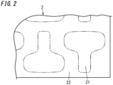
FIG. 2 is a plan view illustrating a removal target part and a body of a metal plate; -
FIGS. 3A to 3C are sectional views illustrating a method for manufacturing the seatbelt tongue plate; and -
FIG. 4 is a side view illustrating a main part of an end of a product obtained by a conventional blanking process. - The present embodiment relates to a method for manufacturing a metal product.
- An embodiment of the present invention will be described below with reference to the drawings.
- The metal product made by the manufacturing process of the present embodiment is a seatbelt tongue plate 1 as shown in
FIG. 1A . The seatbelt tongue plate 1 is used in a seat belt device. - The seatbelt tongue plate 1 is manufactured by performing a blanking process of the present embodiment on the metal plate 2. The seatbelt tongue plate 1 obtained by the blanking process of the present embodiment has an end surface which is prescribed as shown in
FIG. 1B . The end surface has abeveled surface 15, asheared surface 17, afracture surface 16, asheared surface 17, and abeveled surface 15 in order from one edge portion to the other edge portion in a thickness direction of the seatbelt tongue plate 1. In other words, thefracture surface 16 produced in the present embodiment is narrower than the thickness of the seatbelt tongue plate 1 and is formed at a middle location in the thickness direction of the seatbelt tongue plate 1. Thus, thefracture surfaces 16 are not formed at the edge portions of the end surface serving as a cut surface, and therefore, the seatbelt tongue plate 1 produced in the present embodiment can have breaking strength that is conventionally unavailable. - The seatbelt tongue plate 1 produced in the present embodiment includes a
grip 11 and aninsertion part 13. - Note that in the present embodiment, the end surface which is prescribed is an end surface formed over the entirety of the outer perimeter of the seatbelt tongue plate 1, but only part of the outer perimeter may be the prescribed end surface.
- The
grip 11 is a part which is to be held by a user when the user attaches the seatbelt tongue plate 1 to a buckle. For example, part or the entirety of thegrip 11 is covered with a resin molding part (not shown). Thegrip 11 has a throughhole 12 which a webbing belt is to run through. - The
insertion part 13 is a part to be inserted into the buckle. The seatbelt tongue plate 1 is held by the buckle by inserting theinsertion part 13 into the buckle. Theinsertion part 13 extends from thegrip 11 and is integrally formed with thegrip 11. Theinsertion part 13 is narrower than thegrip 11 and has ahook hole 14 to which the buckle is hooked. Thehook hole 14 is formed at a center part in a width direction and in a tip portion of an extension direction of theinsertion part 13. - The seatbelt tongue plate 1 having the configuration described above is manufactured by the following method. The method for manufacturing the seatbelt tongue plate 1 (hereinafter referred to as a manufacturing method of the present embodiment) will be described below.
- The manufacturing method of the present embodiment is a method for obtaining the seatbelt tongue plate 1 as a metal product by performing a blanking process on the metal plate 2 (work piece). As the metal plate 2, for example, an iron plate or a stainless steel plate having a thickness of 3 mm is preferably used. As shown in
FIG. 2 , the metal plate 2 prior to processing has an area corresponding to abody 21 which is formed into a metal product by shaping and an area corresponding to aremoval target part 22 which is cut and removed from thebody 21 by the shaping. Note that in the metal plate 2, thebody 21 and theremoval target part 22 are indistinguishable in appearance. - The manufacturing method of the present embodiment includes a rough finishing step (optional), a beveling step, a crushing step, and a separation step.
- The rough finishing step is a step of roughly obtaining the plurality of seatbelt tongue plates 1 from the metal plate 2 serving as a base material (the shaped piece roughly obtained by the rough finishing step is referred to as a
work 20 in process). Thework 20 in process includes abody 21 and aremoval target part 22 around thebody 21. After the rough finishing step, theremoval target part 22 is smaller than prior to the rough finishing step. - The beveling step is performed after the optional rough finishing step. As illustrated in
FIG. 3A, 3A , the beveling step is a step of beveling a corner formed between a front surface and the end surface of the seatbelt tongue plate 1 or a corner formed between a back surface and the end surface of the seatbelt tongue plate 1. Chamfering, round beveling, or the like is selected in accordance with the product. The claimed process includes a beveling step as defined in the claims. - The beveling step of the present embodiment is a step of forming the
beveled surfaces 15 at the corners in the thickness direction of the seatbelt tongue plate 1. In the present embodiment, thebeveled surfaces 15 are round surfaces. Note that the round surface is a beveled surface having a curved and outwardly protruding shape. The mold used in the beveling step includes: a pair ofplate holding molds 3 configured to hold thebody 21 by pinching thebody 21 from both sides in a thickness direction of thebody 21; and a pair ofround press molds 4. - The pair of
plate holding molds 3 have shaping surfaces (counter surfaces) which are flat surfaces. The shaping surfaces of the pair ofplate holding molds 3 are apart from each other. Eachround press mold 4 has a shaping surface including a concavely roundedsurface 41 and a flat protrudingsurface 42. Each concavely roundedsurface 41 is continuous with the shaping surface of an adjoining one of theplate holding molds 3. The concavely roundedsurface 41 has an inner side edge which coincides with an outer side edge of theplate holding mold 3. The flat protrudingsurface 42 has an edge which borders the concavely roundedsurface 41 and which coincides with the outer side edge of the concavely roundedsurface 41. - In the beveling step, the
body 21 is placed so as to be pinched between the pair ofplate holding molds 3, and in this state, parts corresponding to corners of thebody 21 and theremoval target part 22 are pressed with the pair ofround press molds 4 from both sides in a thickness direction of thework 20 in process. Thus, thework 20 in process has the corners of thebody 21 which are formed into thebeveled surfaces 15 as compressed round surface, and theremoval target part 22, which is crushed to a certain extent, extends from the end surface of thebody 21. - The crushing step is performed after the beveling step. The crushing step adopts a pair of finishing
press molds 5 instead of the pair ofround press molds 4. The crushing step is, as shown inFIG. 3B , a step of applying force mainly to theremoval target part 22 from both sides in the thickness direction with the pair of finishingpress molds 5 to further crush theremoval target part 22 in the thickness direction, thereby deforming theremoval target part 22 into a thin-walled part 23. A mold adopted in the crushing step includes: the pair ofplate holding molds 3 configured to hold thebody 21 by pinching thebody 21 from the both sides in the thickness direction; and the pair of finishingpress molds 5 configured to crush theremoval target part 22 in the thickness direction. - The pair of finishing
press molds 5 are configured to press theremoval target part 22 of thework 20 in process from both sides in the thickness direction. In addition, the pair of finishingpress molds 5 enable shear force to be applied to the end surface of thework 20 in process to form the sheared surfaces 17 at an upper part and a lower part of the end surface. Accordingly, in the crushing step, pressing theremoval target part 22 with the pair of finishingpress molds 5 from the both sides in the thickness direction to apply compression force to theremoval target part 22 enables theremoval target part 22 to be deformed into the thin-walled part 23 and also enables the shearedsurfaces 17 to be formed at upper and lower parts of the end surface of thebody 21. - The thin-
walled part 23 produced by the crushing step is thinner than the thickness of thebody 21 and is formed at a middle location in the thickness direction of the body 21 (between the front surface and the back surface of the body 21). In the present embodiment, the thin-walled part 23 extends from a center part in the thickness direction of thebody 21 but may be formed at a location deviated to the front surface or the back surface as long as the location is within the thickness of thebody 21. - The separation step is performed after the crushing step. The separation step is a step of separating the thin-
walled part 23 produced by the crushing step from thebody 21. In the separation step, the pair of finishingpress molds 5 and the pair ofplate holding molds 3 are relatively moved from a state directly after theremoval target part 22 is crushed in the crushing step in the thickness direction of the product so as to separate the thin-walled part 23 from thebody 21. As the relative movement between the pair of finishingpress molds 5 and the pair ofplate holding molds 3, one of the pair ofplate holding molds 3 and the pair of finishingpress molds 5 may be fixed and the other may be moved, or both of the pair ofplate holding molds 3 and the pair of finishingpress molds 5 may be moved in the opposite directions. - Note that according to
FIGS. 3A and 3B , the pair ofplate holding molds 3 are displaced with respect to thebody 21 when the beveling step proceeds to the crushing step. In this regard, for example, the pair ofplate holding molds 3 may be moved toward the finishingpress molds 5, or molds different from theplate holding molds 3 used in the beveling step may be used. - The seatbelt tongue plate 1 formed through these steps has the end surface having the
fracture surface 16 formed at a center part in the thickness direction, the pair of shearedsurfaces 17 formed on both outer sides of thefracture surface 16 in the thickness direction, and thebeveled surfaces 15 are formed on both outer sides of the pair of shearedsurfaces 17 in the thickness direction. Thus, the seatbelt tongue plate 1 of the present embodiment has corners where the fracture surfaces 16 are not formed, and therefore, even if excessive external force is applied to the seatbelt tongue plate 1, it is possible to suppress the formation of cracks from fine unevenness of thefracture surface 16, and it is possible to suppress the formation of a crack starting from the fine unevenness. As a result, the seatbelt tongue plate 1 of the present embodiment enables the strength of the product to be increased. - The manufacturing method of the present embodiment as described above includes the rough finishing step, the beveling step, the crushing step, and the separation step. However, the rough finishing step may be performed as required and is not necessarily required.
- The thin-
walled part 23 in the embodiment is formed at the center part in the thickness direction of thebody 21 but may alternatively be formed at a location deviated to the front surface or the back surface in the thickness direction and is not formed at least at the corner. That is, the thin-walled part 23 is formed at least at a middle location in the thickness direction of thebody 21. The manufacturing method of the embodiment described above enables the thin-walled part 23 to be formed at a location deviated to the front surface or the back surface in the thickness direction of the end surface of thebody 21, and therefore, it is possible to accordingly set the location of thefracture surface 16 as required. - The manufacturing method of the embodiment is the method for manufacturing the seatbelt tongue plate 1 as a metal product but is not limited to the manufacturing method of the seatbelt tongue plate 1 and is generally applicable to metal processing. Moreover, the manufacturing method of the embodiment may be applied to the method for cutting the metal plate 2. Thus, the cut surface of the metal plate 2 can be an end surface which is smooth and which hardly cracks.
- The
removal target part 22 of the embodiment is a part other than thebody 21 of the metal plate. However, it is at least an outer periphery of thebody 21 that is to be deformed into the thin-walled part 23, and it is not necessary to deform the entirety of theremoval target part 22 into the thin-walled part 23. - Comparative experiment on the tensile strength was performed between a metal piece produced from a metal plate by the manufacturing method of the embodiment, and a metal piece punched out from a metal plate by a conventional manufacturing method. In the following description, the metal piece produced by the manufacturing method of the embodiment is referred to as a metal piece of an example and the metal piece manufactured by the conventional manufacturing method is referred to as a metal piece of a comparative example.
- The metal piece of the example is a metal piece manufactured from a metal plate being made of mechanical structure carbon steel (S55C), having a plate thickness of 3.0 mm, and having hardness of 45 ± 2 HRC by the manufacturing method of the embodiment to have a rectangular shape of 25.4 mm (W) × 100 mm (L).
- A metal piece of Comparative Example 1 is a metal piece manufactured from a metal plate being made of mechanical structure carbon steel (S55C) as the same material as Example, having a plate thickness of 3.0 mm, and having hardness of 45 ± 2 HRC by the fine blanking process to have a rectangular shape of 25.4 mm (W) × 100 mm (L). Burrs formed on the fracture surface were left intact.
- A metal piece of Comparative Example 2 is a metal piece manufactured from a metal plate being made of mechanical structure carbon steel (S55C) as the same material as Example, having a plate thickness of 3.0 mm, and having hardness of 45 ± 2 HRC by the fine blanking process to have a rectangular shape of 25.4 mm (W) × 100 mm (L). Burrs formed on the fracture surface were removed by chamfering.
- A metal piece of Comparative Example 3 is a metal piece manufactured from a metal plate being made of mechanical structure carbon steel (S55C) as the same material as Example, having a plate thickness of 3.0 mm, and having hardness of 45 ± 2 HRC by the punching process with a press to have a rectangular shape of 25.4 mm (W) × 100 mm (L).
- A metal piece of Comparative Example 4 is a metal piece manufactured from a metal plate being made of mechanical structure carbon steel (S55C) as the same material as Example, having a plate thickness of 3.0 mm, and having hardness of 45 ± 2 HRC with a ire electric discharge machine to have a rectangular shape of 25.4 mm (W) × 100 mm (L).
- Test condition were such that both longitudinal ends of each of the metal pieces of Example and Comparative Examples 1 to 4 were held with a test apparatus, and in this state, pull force was applied in directions away from each other along the longitudinal direction of the metal piece and was gradually increased, and the pull force at fracture of the metal plate was measured. Five test pieces were produced for each of the metal piece of Example and the metal pieces of Comparative Examples 1 to 4, and the five test pieces were tested under the above-described conditions. An average value was then calculated from values obtained from the five test pieces, and the average values of the test pieces of Example and Comparative Examples 1 to 4 were compared.
-
[Table 1] Load At Fracture [kN] Part Where Crack Is Formed Example 50.5 Principal Surface Comparative Example 1 37.8 End Surface (Fracture surface) Comparative Example 2 38.2 End Surface (Fracture surface) Comparative Example 3 34.3 End Surface (Fracture surface) Comparative Example 4 42 Edge - The test showed that the metal piece of Example has higher tensile strength than the metal pieces of Comparative Examples 1 to 4.
- Situations at breakage was such that the metal piece of Example was cracked from either of principal surfaces, not the fracture surface, whereas the metal pieces of Comparative Examples 1 to 3 were cracked from their fracture surfaces, and the metal piece of Comparative Example 4 was cracked from its edge.
- The reason why a difference in tensile strength occurs between the metal piece of Example and the metal piece of Comparative Example 4 is probably that an edge portion of the metal piece of Example is beveled to be a compressed round surface (round pressed surface), and therefore, the metal piece of Example is hardly fractured from the edge, which contributes to the increase of the tensile strength.
- As described above, the method for cutting the metal plate 2 of the embodiment has the following features. That is, the method for cutting the metal plate 2 of the embodiment includes the crushing step and the separation step. The crushing step is a step of crushing the
removal target part 22 of the metal plate 2 in a thickness direction of the metal plate 2 by applying, to theremoval target part 22, force from both sides in the thickness direction so as to deform theremoval target part 22 into the thin-walled part 23. The separation step is a step of separating, after crushing step, the thin-walled part 23 from thebody 21 of the metal plate 2. The method for cutting the metal plate 2 having these features is hereinafter referred to as the cutting method of the metal plate 2 of the first aspect. - The cutting method of the metal plate 2 of the first aspect enables a fracture surface of the
body 21 to be located at a middle part in a thickness direction of the end surface of thebody 21. Thus, as compared with a conventional product having a fracture surface formed on a corner of abody 21, cracks are less likely formed from the fine unevenness of the fracture surface, and the strength of thebody 21 can be improved. - The method for manufacturing the metal product of the embodiment has the following features. That is, the method for manufacturing the metal product of the embodiment is a method for manufacturing a metal product by cutting off a
removal target part 22 from a metal plate 2. The method for manufacturing a metal product of the embodiment includes a crushing step and a separation step. The crushing step is a step of crushing aremoval target part 22 of the metal plate 2 in a thickness direction of the metal plate 2 by applying, to theremoval target part 22, force from both sides in the thickness direction so as to deform theremoval target part 22 into a thin-walled part 23. The separation step is a step of separating, after the crushing step, the thin-walled part 23 from abody 21 of the metal plate 2 to obtain the metal product. The method for manufacturing a metal product having these features is hereinafter referred to as a manufacturing method of a metal product of a first aspect. - The manufacturing method of the metal product of the first aspect enables a fracture surface of the metal product to be located at a middle part in a thickness direction of the end surface of the
body 21. Thus, as compared with a conventional product having a fracture surface formed on a corner of a metal product, cracks are less likely formed from the fine unevenness of the fracture surface, and the strength of the metal product can be improved. - The method for manufacturing the metal product of the embodiment has the following additional features. That is, in a method for manufacturing a metal product referring to the manufacturing method of the metal product of the first aspect, the metal product is a seatbelt tongue plate 1 which is to be attachably and detachably inserted into a buckle of a seat belt device. The method for manufacturing the metal product is hereinafter referred to as a manufacturing method of a metal product of a second aspect.
- According to the manufacturing method of the metal product of the second aspect, it is possible to increase the strength of the seatbelt tongue plate 1, which is easily subjected to instantaneous excessive external force.
- The metal product produced by the method of manufacturing of the embodiment has the following features. Although explained through different aspects below, the metal product in and of itself does not form part of the claims but is a by-product of the claimed method. That is, the metal product produced in the embodiment is a metal product. formed by cutting off a
removal target part 22 from a metal plate 2. The metal product includes an end surface having afracture surface 16 obtained by cutting off the removal targetremoval target part 22, thefracture surface 16 being shorter than a thickness of the metal product in a thickness direction of the metal product, the fracture surface being at a middle location in the thickness direction of the metal product. The metal product having these features is hereinafter referred to as a metal product of a first aspect. - According to the metal product of the first aspect, the
fracture surface 16 is formed at the middle location in the thickness direction of the metal product and is not formed at the corner of thickness direction, and therefore, it is possible to obtain the metal product in which the formation of a crack starting from fine unevenness on the fracture surface can be suppressed and which has higher strength than conventional product. - The metal product of the embodiment has the following additional features. That is, in the metal product of the first aspect, the end surface of the metal product has: a pair of sheared
surfaces 17 on both outer sides of thefracture surface 16 in the thickness direction of the metal product; and a pair ofbeveled surfaces 15 on both outer sides of the sheared surfaces 17 in the thickness direction of the metal product. The metal product having this feature is hereinafter referred to as a metal product of a second aspect. - According to the metal product of the second aspect, the sheared surfaces 17 and the
beveled surfaces 15 are provided on the both sides of thefracture surface 16 in the thickness direction, and therefore, the end surface metal product including the above-mentioned surfaces (cut end surface) is smooth in appearance, and it is possible to further suppress the formation of cracks. - The metal product of the embodiment has the following additional features. That is, in the metal product of the second aspect, each of the pair of
beveled surfaces 15 is a compressed rounded surface. The metal product having the feature is hereinafter referred to as a metal product of a third aspect. - According to the metal product of third aspect, each
beveled surface 15 is a compressed rounded surface, it is possible to further suppress the formation of cracks at the corners. - The metal product of the embodiment has the following additional features. That is, the metal product of the embodiment referring to the metal product of any one of the first to third aspects, the metal product is a seatbelt tongue plate 1 which is to be attachably and detachably inserted into a buckle of a seat belt device. The metal product having this feature is hereinafter referred to as a metal product of a fourth aspect.
- According to the metal product of fourth aspect, the seatbelt tongue plate 1 can be made stronger in strength than conventional products.
-
- 1
- SEATBELT TONGUE PLATE
- 15
- BEVELED SURFACE
- 16
- FRACTURE SURFACE
- 17
- SHEARED SURFACE
- 2
- METAL PLATE
- 21
- BODY
- 22
- REMOVAL TARGET PART
- 23
- THIN-WALLED PART
Claims (2)
- A method for manufacturing a metal product by cutting off a removal target part (22) from a metal plate (2),
the metal plate (2) including, prior to processing, an area corresponding to a body (21) which is formed into the metal product by shaping and an area corresponding to the removal target part (22) which is cut and removed from the body (21) by the shaping, the body (21) and the removal target part (22) being indistinguishable in appearance in the metal plate (2),
the method comprising:a beveling step of placing the body (21) so as to be pinched between a pair of plate holding molds (3) having flat shaping surfaces, and in this state, pressing parts corresponding to corners of the body (21) and the removal target part (22) with a pair of round press molds (4) from both sides in a thickness direction of the metal plate (2), so that the metal plate (2) has the corners of the body (21) which are formed into the beveled surfaces (15) as compressed round surface, and the removal target part (22), which is crushed, extends from the end surface of the body (21), wherein each round press mold (4) has a shaping surface including a concavely rounded surface (41) and a flat protruding surface (42),a crushing step of crushing, after the beveling step, with a pair of finishing press molds (5) instead of the pair of round press molds (4), the removal target part (22) in the thickness direction of the metal plate (2) by applying, to the removal target part (22), force from both sides in the thickness direction so as to deform the removal target part (22) into a thin-walled part (23), wherein the pair of finishing press molds (5) are configured to press the removal target part (22) of the metal plate (2) from both sides in the thickness direction and to enable shear force to be applied to the end surface of the metal plate (2) to form sheared surfaces (17) at an upper part and a lower part of the end surface, wherein the mold adopted in the crushing step includes in addition to the pair of finishing press molds (5) a pair of plate holding molds (3) configured to hold the body (21) by pinching the body (21) from both sides in the thickness direction, anda separation step of separating, after the crushing step, the thin-walled part (23) from the body (21) of the metal plate (2) to obtain the metal product. - The method of claim 1, wherein
the metal product is a seatbelt tongue plate (1) which is to be attachably and detachably inserted into a buckle of a seat belt device.
Applications Claiming Priority (1)
| Application Number | Priority Date | Filing Date | Title |
|---|---|---|---|
| PCT/JP2017/023702 WO2019003333A1 (en) | 2017-06-28 | 2017-06-28 | Method for cutting metal plate, method for manufacturing metal molding, and metal molding |
Publications (4)
| Publication Number | Publication Date |
|---|---|
| EP3646962A1 EP3646962A1 (en) | 2020-05-06 |
| EP3646962A4 EP3646962A4 (en) | 2020-06-17 |
| EP3646962B1 true EP3646962B1 (en) | 2024-07-31 |
| EP3646962C0 EP3646962C0 (en) | 2024-07-31 |
Family
ID=64740473
Family Applications (1)
| Application Number | Title | Priority Date | Filing Date |
|---|---|---|---|
| EP17915373.9A Active EP3646962B1 (en) | 2017-06-28 | 2017-06-28 | Method for cutting metal plate, method for manufacturing metal molding, and metal molding |
Country Status (5)
| Country | Link |
|---|---|
| US (1) | US11247256B2 (en) |
| EP (1) | EP3646962B1 (en) |
| JP (1) | JP6810265B2 (en) |
| CN (1) | CN110799280B (en) |
| WO (1) | WO2019003333A1 (en) |
Families Citing this family (6)
| Publication number | Priority date | Publication date | Assignee | Title |
|---|---|---|---|---|
| JP7196625B2 (en) | 2019-01-17 | 2022-12-27 | トヨタ自動車株式会社 | Sulfide solid electrolyte particles, manufacturing method thereof, and all-solid battery |
| JP7156048B2 (en) | 2019-01-17 | 2022-10-19 | トヨタ自動車株式会社 | Sulfide solid electrolyte particles and all-solid battery |
| WO2021193308A1 (en) * | 2020-03-27 | 2021-09-30 | ソニーグループ株式会社 | Information processing device, information processing method, and information processing program |
| CN113579069B (en) * | 2021-09-28 | 2021-12-31 | 江苏麦格美节能科技有限公司 | Local stamping device of stainless steel sheet metal |
| AT525435B1 (en) * | 2021-10-29 | 2023-04-15 | Hrach Thomas | Process and device for producing a calibrated stamped part |
| US12076775B2 (en) * | 2022-03-30 | 2024-09-03 | Hsiang-Hung Wang | Method for chamfering installation position of water control valve of faucet body |
Family Cites Families (23)
| Publication number | Priority date | Publication date | Assignee | Title |
|---|---|---|---|---|
| US4353235A (en) * | 1980-06-17 | 1982-10-12 | Kaiser Steel Corporation | Edge preforming of metal plate |
| JPH0665442B2 (en) * | 1989-04-13 | 1994-08-24 | 株式会社ユタカ技研 | Cutting method |
| JPH07227627A (en) * | 1994-02-22 | 1995-08-29 | Toyota Motor Corp | Press punching method |
| DE69617276T2 (en) * | 1995-01-11 | 2002-05-23 | Yugengaisha Mutsumichi Kenkyujo, Hamamatsu | Seat belt connector fitting and method of manufacturing the same |
| JP3138624B2 (en) * | 1995-12-15 | 2001-02-26 | 有限会社睦道研究所 | Manufacturing method of belt connection metal fittings |
| JP2744963B2 (en) * | 1995-11-14 | 1998-04-28 | 武田工業株式会社 | Metal plate punching method |
| JP2002361669A (en) * | 2001-06-12 | 2002-12-18 | Sunstar Group Engineering Inc | Press molding method for three-dimensional shaped product |
| JP2004167547A (en) * | 2002-11-20 | 2004-06-17 | Nakamura Mfg Co Ltd | Method for shearing sheet |
| JP4879596B2 (en) | 2005-02-15 | 2012-02-22 | 日本精工株式会社 | Method for producing metal member having through hole |
| JP2006255740A (en) | 2005-03-16 | 2006-09-28 | Asai Kosan Kk | Fine blanking press |
| CN101862785B (en) * | 2010-07-02 | 2012-01-25 | 金德精密配件(苏州)有限公司 | Burr-free punching process for metal sheet |
| CN201815586U (en) * | 2010-10-21 | 2011-05-04 | 天津海鸥表业集团有限公司 | Male mold structure for punching mold with slotted hole |
| JP5510533B1 (en) | 2012-12-17 | 2014-06-04 | Jfeスチール株式会社 | Press forming method |
| RU2636426C2 (en) * | 2013-01-07 | 2017-11-23 | Ниппон Стил Энд Сумитомо Метал Корпорейшн | Compacted component and method and device for its manufacture |
| DE102013008632A1 (en) | 2013-05-18 | 2014-11-20 | Ulrich Bruhnke | Method and device for separating hollow chamber profiles |
| ES2818648T3 (en) * | 2013-12-06 | 2021-04-13 | Nippon Steel Corp | Die casting device and production method of die cast article using such casting device |
| KR20160090430A (en) * | 2015-01-21 | 2016-08-01 | 현대자동차주식회사 | The apparatus and method of quality improvement for steel plate shearing edge |
| WO2016125730A1 (en) * | 2015-02-04 | 2016-08-11 | 新日鐵住金株式会社 | Cutting and machining device and cutting and machining method |
| CN107249774B (en) * | 2015-02-25 | 2019-09-24 | 日本制铁株式会社 | Shearing method |
| JP2016159300A (en) * | 2015-02-26 | 2016-09-05 | トヨタ自動車株式会社 | Method for processing metal plate |
| EP3156172A1 (en) * | 2015-10-12 | 2017-04-19 | BAE Systems PLC | Metal object production |
| CN109092976B (en) * | 2016-06-28 | 2021-01-01 | 中国航发南方工业有限公司 | Female die for stamping thin plate |
| US10518740B2 (en) * | 2018-02-27 | 2019-12-31 | Ford Global Technologies, Llc | Seatbelt assembly |
-
2017
- 2017-06-28 US US16/626,920 patent/US11247256B2/en active Active
- 2017-06-28 EP EP17915373.9A patent/EP3646962B1/en active Active
- 2017-06-28 JP JP2019526454A patent/JP6810265B2/en active Active
- 2017-06-28 CN CN201780092486.8A patent/CN110799280B/en active Active
- 2017-06-28 WO PCT/JP2017/023702 patent/WO2019003333A1/en not_active Ceased
Also Published As
| Publication number | Publication date |
|---|---|
| CN110799280A (en) | 2020-02-14 |
| JPWO2019003333A1 (en) | 2020-04-09 |
| JP6810265B2 (en) | 2021-01-06 |
| CN110799280B (en) | 2022-01-28 |
| WO2019003333A1 (en) | 2019-01-03 |
| US20200130041A1 (en) | 2020-04-30 |
| EP3646962C0 (en) | 2024-07-31 |
| EP3646962A4 (en) | 2020-06-17 |
| US11247256B2 (en) | 2022-02-15 |
| EP3646962A1 (en) | 2020-05-06 |
Similar Documents
| Publication | Publication Date | Title |
|---|---|---|
| EP3646962B1 (en) | Method for cutting metal plate, method for manufacturing metal molding, and metal molding | |
| CN107249774B (en) | Shearing method | |
| CN101678429B (en) | Method for stamping sheet metal parts | |
| US11224909B2 (en) | Protrusion molding device, protrusion molding method, and molded article | |
| KR101454793B1 (en) | Two step shearing method of hot-stamped ultra-high-strength material for preventing damage of press cutting mold | |
| EP3320997A1 (en) | Protrusion molding device, protrusion molding method, and molded article | |
| CN117897239A (en) | Method for improving delayed fracture characteristics of metal sheet, method for manufacturing blank, method for manufacturing press-formed product, and press-formed product | |
| CN113365752B (en) | Method for manufacturing stamped member and method for manufacturing blank | |
| JP2002321022A (en) | Method for precise blanking in metal press working | |
| KR101991194B1 (en) | Method of punching, method of manufacturing press-molded article, and press-molded article | |
| JPH07116767A (en) | Manufacturing method of winding shaft for seat belt | |
| KR101915289B1 (en) | Blanking Shear a molding machine for car body | |
| KR102836645B1 (en) | Press forming device | |
| RU2409444C2 (en) | Method of finish cutting with reduction | |
| KR101674764B1 (en) | Apparatus and Method for press forming | |
| JPH07108418B2 (en) | Sheet metal work manufacturing method | |
| JP2904085B2 (en) | Punching press equipment | |
| KR101006051B1 (en) | Blanking method | |
| KR101555292B1 (en) | Forming metallic mold and Forming method to bend in multistage | |
| JP3696656B2 (en) | Punching method | |
| KR101480440B1 (en) | Making method of pan nut | |
| JP2019171434A (en) | Punch structure of press metal die, press metal die, press-molded product manufacturing method and press molded product | |
| JPH02147129A (en) | Punching/coining method | |
| KR101665797B1 (en) | Method and Apparatus for press forming | |
| CN205967078U (en) | Automatic chamfer mould of bending |
Legal Events
| Date | Code | Title | Description |
|---|---|---|---|
| STAA | Information on the status of an ep patent application or granted ep patent |
Free format text: STATUS: THE INTERNATIONAL PUBLICATION HAS BEEN MADE |
|
| PUAI | Public reference made under article 153(3) epc to a published international application that has entered the european phase |
Free format text: ORIGINAL CODE: 0009012 |
|
| STAA | Information on the status of an ep patent application or granted ep patent |
Free format text: STATUS: REQUEST FOR EXAMINATION WAS MADE |
|
| 17P | Request for examination filed |
Effective date: 20191217 |
|
| AK | Designated contracting states |
Kind code of ref document: A1 Designated state(s): AL AT BE BG CH CY CZ DE DK EE ES FI FR GB GR HR HU IE IS IT LI LT LU LV MC MK MT NL NO PL PT RO RS SE SI SK SM TR |
|
| AX | Request for extension of the european patent |
Extension state: BA ME |
|
| A4 | Supplementary search report drawn up and despatched |
Effective date: 20200520 |
|
| RIC1 | Information provided on ipc code assigned before grant |
Ipc: B21D 53/88 20060101ALI20200514BHEP Ipc: B21D 19/00 20060101ALN20200514BHEP Ipc: B21J 5/02 20060101ALI20200514BHEP Ipc: B21D 28/16 20060101AFI20200514BHEP Ipc: B21D 28/00 20060101ALI20200514BHEP Ipc: B60R 22/18 20060101ALI20200514BHEP Ipc: B21K 23/00 20060101ALI20200514BHEP |
|
| DAV | Request for validation of the european patent (deleted) | ||
| DAX | Request for extension of the european patent (deleted) | ||
| STAA | Information on the status of an ep patent application or granted ep patent |
Free format text: STATUS: EXAMINATION IS IN PROGRESS |
|
| 17Q | First examination report despatched |
Effective date: 20210517 |
|
| GRAP | Despatch of communication of intention to grant a patent |
Free format text: ORIGINAL CODE: EPIDOSNIGR1 |
|
| STAA | Information on the status of an ep patent application or granted ep patent |
Free format text: STATUS: GRANT OF PATENT IS INTENDED |
|
| RIC1 | Information provided on ipc code assigned before grant |
Ipc: B21D 19/00 20060101ALN20240208BHEP Ipc: B21K 23/00 20060101ALI20240208BHEP Ipc: B21J 5/02 20060101ALI20240208BHEP Ipc: B21D 53/88 20060101ALI20240208BHEP Ipc: B60R 22/18 20060101ALI20240208BHEP Ipc: B21D 28/00 20060101ALI20240208BHEP Ipc: B21D 28/16 20060101AFI20240208BHEP |
|
| INTG | Intention to grant announced |
Effective date: 20240223 |
|
| GRAS | Grant fee paid |
Free format text: ORIGINAL CODE: EPIDOSNIGR3 |
|
| GRAA | (expected) grant |
Free format text: ORIGINAL CODE: 0009210 |
|
| STAA | Information on the status of an ep patent application or granted ep patent |
Free format text: STATUS: THE PATENT HAS BEEN GRANTED |
|
| AK | Designated contracting states |
Kind code of ref document: B1 Designated state(s): AL AT BE BG CH CY CZ DE DK EE ES FI FR GB GR HR HU IE IS IT LI LT LU LV MC MK MT NL NO PL PT RO RS SE SI SK SM TR |
|
| REG | Reference to a national code |
Ref country code: CH Ref legal event code: EP Ref country code: GB Ref legal event code: FG4D |
|
| REG | Reference to a national code |
Ref country code: DE Ref legal event code: R096 Ref document number: 602017083784 Country of ref document: DE |
|
| REG | Reference to a national code |
Ref country code: IE Ref legal event code: FG4D |
|
| U01 | Request for unitary effect filed |
Effective date: 20240830 |
|
| U07 | Unitary effect registered |
Designated state(s): AT BE BG DE DK EE FI FR IT LT LU LV MT NL PT RO SE SI Effective date: 20240911 |
|
| PG25 | Lapsed in a contracting state [announced via postgrant information from national office to epo] |
Ref country code: NO Free format text: LAPSE BECAUSE OF FAILURE TO SUBMIT A TRANSLATION OF THE DESCRIPTION OR TO PAY THE FEE WITHIN THE PRESCRIBED TIME-LIMIT Effective date: 20241031 |
|
| PG25 | Lapsed in a contracting state [announced via postgrant information from national office to epo] |
Ref country code: GR Free format text: LAPSE BECAUSE OF FAILURE TO SUBMIT A TRANSLATION OF THE DESCRIPTION OR TO PAY THE FEE WITHIN THE PRESCRIBED TIME-LIMIT Effective date: 20241101 Ref country code: PL Free format text: LAPSE BECAUSE OF FAILURE TO SUBMIT A TRANSLATION OF THE DESCRIPTION OR TO PAY THE FEE WITHIN THE PRESCRIBED TIME-LIMIT Effective date: 20240731 |
|
| PG25 | Lapsed in a contracting state [announced via postgrant information from national office to epo] |
Ref country code: IS Free format text: LAPSE BECAUSE OF FAILURE TO SUBMIT A TRANSLATION OF THE DESCRIPTION OR TO PAY THE FEE WITHIN THE PRESCRIBED TIME-LIMIT Effective date: 20241130 |
|
| PG25 | Lapsed in a contracting state [announced via postgrant information from national office to epo] |
Ref country code: HR Free format text: LAPSE BECAUSE OF FAILURE TO SUBMIT A TRANSLATION OF THE DESCRIPTION OR TO PAY THE FEE WITHIN THE PRESCRIBED TIME-LIMIT Effective date: 20240731 |
|
| PG25 | Lapsed in a contracting state [announced via postgrant information from national office to epo] |
Ref country code: ES Free format text: LAPSE BECAUSE OF FAILURE TO SUBMIT A TRANSLATION OF THE DESCRIPTION OR TO PAY THE FEE WITHIN THE PRESCRIBED TIME-LIMIT Effective date: 20240731 Ref country code: RS Free format text: LAPSE BECAUSE OF FAILURE TO SUBMIT A TRANSLATION OF THE DESCRIPTION OR TO PAY THE FEE WITHIN THE PRESCRIBED TIME-LIMIT Effective date: 20241031 |
|
| PG25 | Lapsed in a contracting state [announced via postgrant information from national office to epo] |
Ref country code: RS Free format text: LAPSE BECAUSE OF FAILURE TO SUBMIT A TRANSLATION OF THE DESCRIPTION OR TO PAY THE FEE WITHIN THE PRESCRIBED TIME-LIMIT Effective date: 20241031 Ref country code: PL Free format text: LAPSE BECAUSE OF FAILURE TO SUBMIT A TRANSLATION OF THE DESCRIPTION OR TO PAY THE FEE WITHIN THE PRESCRIBED TIME-LIMIT Effective date: 20240731 Ref country code: NO Free format text: LAPSE BECAUSE OF FAILURE TO SUBMIT A TRANSLATION OF THE DESCRIPTION OR TO PAY THE FEE WITHIN THE PRESCRIBED TIME-LIMIT Effective date: 20241031 Ref country code: IS Free format text: LAPSE BECAUSE OF FAILURE TO SUBMIT A TRANSLATION OF THE DESCRIPTION OR TO PAY THE FEE WITHIN THE PRESCRIBED TIME-LIMIT Effective date: 20241130 Ref country code: HR Free format text: LAPSE BECAUSE OF FAILURE TO SUBMIT A TRANSLATION OF THE DESCRIPTION OR TO PAY THE FEE WITHIN THE PRESCRIBED TIME-LIMIT Effective date: 20240731 Ref country code: GR Free format text: LAPSE BECAUSE OF FAILURE TO SUBMIT A TRANSLATION OF THE DESCRIPTION OR TO PAY THE FEE WITHIN THE PRESCRIBED TIME-LIMIT Effective date: 20241101 Ref country code: ES Free format text: LAPSE BECAUSE OF FAILURE TO SUBMIT A TRANSLATION OF THE DESCRIPTION OR TO PAY THE FEE WITHIN THE PRESCRIBED TIME-LIMIT Effective date: 20240731 |
|
| PG25 | Lapsed in a contracting state [announced via postgrant information from national office to epo] |
Ref country code: SM Free format text: LAPSE BECAUSE OF FAILURE TO SUBMIT A TRANSLATION OF THE DESCRIPTION OR TO PAY THE FEE WITHIN THE PRESCRIBED TIME-LIMIT Effective date: 20240731 |
|
| PG25 | Lapsed in a contracting state [announced via postgrant information from national office to epo] |
Ref country code: CZ Free format text: LAPSE BECAUSE OF FAILURE TO SUBMIT A TRANSLATION OF THE DESCRIPTION OR TO PAY THE FEE WITHIN THE PRESCRIBED TIME-LIMIT Effective date: 20240731 |
|
| PG25 | Lapsed in a contracting state [announced via postgrant information from national office to epo] |
Ref country code: SK Free format text: LAPSE BECAUSE OF FAILURE TO SUBMIT A TRANSLATION OF THE DESCRIPTION OR TO PAY THE FEE WITHIN THE PRESCRIBED TIME-LIMIT Effective date: 20240731 |
|
| PLBE | No opposition filed within time limit |
Free format text: ORIGINAL CODE: 0009261 |
|
| STAA | Information on the status of an ep patent application or granted ep patent |
Free format text: STATUS: NO OPPOSITION FILED WITHIN TIME LIMIT |
|
| 26N | No opposition filed |
Effective date: 20250501 |
|
| U20 | Renewal fee for the european patent with unitary effect paid |
Year of fee payment: 9 Effective date: 20250627 |
|
| REG | Reference to a national code |
Ref country code: CH Ref legal event code: H13 Free format text: ST27 STATUS EVENT CODE: U-0-0-H10-H13 (AS PROVIDED BY THE NATIONAL OFFICE) Effective date: 20260127 |
|
| PG25 | Lapsed in a contracting state [announced via postgrant information from national office to epo] |
Ref country code: MC Free format text: LAPSE BECAUSE OF FAILURE TO SUBMIT A TRANSLATION OF THE DESCRIPTION OR TO PAY THE FEE WITHIN THE PRESCRIBED TIME-LIMIT Effective date: 20240731 |
|
| GBPC | Gb: european patent ceased through non-payment of renewal fee |
Effective date: 20250628 |
|
| PG25 | Lapsed in a contracting state [announced via postgrant information from national office to epo] |
Ref country code: GB Free format text: LAPSE BECAUSE OF NON-PAYMENT OF DUE FEES Effective date: 20250628 |
|
| PG25 | Lapsed in a contracting state [announced via postgrant information from national office to epo] |
Ref country code: IE Free format text: LAPSE BECAUSE OF NON-PAYMENT OF DUE FEES Effective date: 20250628 |
|
| PG25 | Lapsed in a contracting state [announced via postgrant information from national office to epo] |
Ref country code: CH Free format text: LAPSE BECAUSE OF NON-PAYMENT OF DUE FEES Effective date: 20250630 |