EP3645951B1 - Dispositif de refroidissement destiné à être embarqué dans un dispositif de vision infrarouge à élément déformable - Google Patents
Dispositif de refroidissement destiné à être embarqué dans un dispositif de vision infrarouge à élément déformable Download PDFInfo
- Publication number
- EP3645951B1 EP3645951B1 EP18733310.9A EP18733310A EP3645951B1 EP 3645951 B1 EP3645951 B1 EP 3645951B1 EP 18733310 A EP18733310 A EP 18733310A EP 3645951 B1 EP3645951 B1 EP 3645951B1
- Authority
- EP
- European Patent Office
- Prior art keywords
- piston
- deformable element
- cooling device
- coupling member
- crank
- Prior art date
- Legal status (The legal status is an assumption and is not a legal conclusion. Google has not performed a legal analysis and makes no representation as to the accuracy of the status listed.)
- Active
Links
Images




Classifications
-
- F—MECHANICAL ENGINEERING; LIGHTING; HEATING; WEAPONS; BLASTING
- F25—REFRIGERATION OR COOLING; COMBINED HEATING AND REFRIGERATION SYSTEMS; HEAT PUMP SYSTEMS; MANUFACTURE OR STORAGE OF ICE; LIQUEFACTION SOLIDIFICATION OF GASES
- F25B—REFRIGERATION MACHINES, PLANTS OR SYSTEMS; COMBINED HEATING AND REFRIGERATION SYSTEMS; HEAT PUMP SYSTEMS
- F25B9/00—Compression machines, plants or systems, in which the refrigerant is air or other gas of low boiling point
- F25B9/14—Compression machines, plants or systems, in which the refrigerant is air or other gas of low boiling point characterised by the cycle used, e.g. Stirling cycle
-
- F—MECHANICAL ENGINEERING; LIGHTING; HEATING; WEAPONS; BLASTING
- F01—MACHINES OR ENGINES IN GENERAL; ENGINE PLANTS IN GENERAL; STEAM ENGINES
- F01B—MACHINES OR ENGINES, IN GENERAL OR OF POSITIVE-DISPLACEMENT TYPE, e.g. STEAM ENGINES
- F01B9/00—Reciprocating-piston machines or engines characterised by connections between pistons and main shafts, not specific to groups F01B1/00 - F01B7/00
- F01B9/02—Reciprocating-piston machines or engines characterised by connections between pistons and main shafts, not specific to groups F01B1/00 - F01B7/00 with crankshaft
-
- F—MECHANICAL ENGINEERING; LIGHTING; HEATING; WEAPONS; BLASTING
- F02—COMBUSTION ENGINES; HOT-GAS OR COMBUSTION-PRODUCT ENGINE PLANTS
- F02G—HOT GAS OR COMBUSTION-PRODUCT POSITIVE-DISPLACEMENT ENGINE PLANTS; USE OF WASTE HEAT OF COMBUSTION ENGINES; NOT OTHERWISE PROVIDED FOR
- F02G1/00—Hot gas positive-displacement engine plants
- F02G1/04—Hot gas positive-displacement engine plants of closed-cycle type
- F02G1/043—Hot gas positive-displacement engine plants of closed-cycle type the engine being operated by expansion and contraction of a mass of working gas which is heated and cooled in one of a plurality of constantly communicating expansible chambers, e.g. Stirling cycle type engines
- F02G1/053—Component parts or details
-
- F—MECHANICAL ENGINEERING; LIGHTING; HEATING; WEAPONS; BLASTING
- F16—ENGINEERING ELEMENTS AND UNITS; GENERAL MEASURES FOR PRODUCING AND MAINTAINING EFFECTIVE FUNCTIONING OF MACHINES OR INSTALLATIONS; THERMAL INSULATION IN GENERAL
- F16C—SHAFTS; FLEXIBLE SHAFTS; ELEMENTS OR CRANKSHAFT MECHANISMS; ROTARY BODIES OTHER THAN GEARING ELEMENTS; BEARINGS
- F16C7/00—Connecting-rods or like links pivoted at both ends; Construction of connecting-rod heads
- F16C7/08—Connecting-rods or like links pivoted at both ends; Construction of connecting-rod heads made from sheet metal
-
- F—MECHANICAL ENGINEERING; LIGHTING; HEATING; WEAPONS; BLASTING
- F16—ENGINEERING ELEMENTS AND UNITS; GENERAL MEASURES FOR PRODUCING AND MAINTAINING EFFECTIVE FUNCTIONING OF MACHINES OR INSTALLATIONS; THERMAL INSULATION IN GENERAL
- F16J—PISTONS; CYLINDERS; SEALINGS
- F16J7/00—Piston-rods
-
- G—PHYSICS
- G01—MEASURING; TESTING
- G01J—MEASUREMENT OF INTENSITY, VELOCITY, SPECTRAL CONTENT, POLARISATION, PHASE OR PULSE CHARACTERISTICS OF INFRARED, VISIBLE OR ULTRAVIOLET LIGHT; COLORIMETRY; RADIATION PYROMETRY
- G01J5/00—Radiation pyrometry, e.g. infrared or optical thermometry
- G01J5/02—Constructional details
- G01J5/06—Arrangements for eliminating effects of disturbing radiation; Arrangements for compensating changes in sensitivity
- G01J5/061—Arrangements for eliminating effects of disturbing radiation; Arrangements for compensating changes in sensitivity by controlling the temperature of the apparatus or parts thereof, e.g. using cooling means or thermostats
-
- G—PHYSICS
- G02—OPTICS
- G02B—OPTICAL ELEMENTS, SYSTEMS OR APPARATUS
- G02B23/00—Telescopes, e.g. binoculars; Periscopes; Instruments for viewing the inside of hollow bodies; Viewfinders; Optical aiming or sighting devices
- G02B23/12—Telescopes, e.g. binoculars; Periscopes; Instruments for viewing the inside of hollow bodies; Viewfinders; Optical aiming or sighting devices with means for image conversion or intensification
-
- F—MECHANICAL ENGINEERING; LIGHTING; HEATING; WEAPONS; BLASTING
- F02—COMBUSTION ENGINES; HOT-GAS OR COMBUSTION-PRODUCT ENGINE PLANTS
- F02G—HOT GAS OR COMBUSTION-PRODUCT POSITIVE-DISPLACEMENT ENGINE PLANTS; USE OF WASTE HEAT OF COMBUSTION ENGINES; NOT OTHERWISE PROVIDED FOR
- F02G2243/00—Stirling type engines having closed regenerative thermodynamic cycles with flow controlled by volume changes
- F02G2243/30—Stirling type engines having closed regenerative thermodynamic cycles with flow controlled by volume changes having their pistons and displacers each in separate cylinders
- F02G2243/34—Regenerative displacers having their cylinders at right angle, e.g. "Robinson" engines
-
- F—MECHANICAL ENGINEERING; LIGHTING; HEATING; WEAPONS; BLASTING
- F02—COMBUSTION ENGINES; HOT-GAS OR COMBUSTION-PRODUCT ENGINE PLANTS
- F02G—HOT GAS OR COMBUSTION-PRODUCT POSITIVE-DISPLACEMENT ENGINE PLANTS; USE OF WASTE HEAT OF COMBUSTION ENGINES; NOT OTHERWISE PROVIDED FOR
- F02G2270/00—Constructional features
- F02G2270/40—Piston assemblies
-
- F—MECHANICAL ENGINEERING; LIGHTING; HEATING; WEAPONS; BLASTING
- F02—COMBUSTION ENGINES; HOT-GAS OR COMBUSTION-PRODUCT ENGINE PLANTS
- F02G—HOT GAS OR COMBUSTION-PRODUCT POSITIVE-DISPLACEMENT ENGINE PLANTS; USE OF WASTE HEAT OF COMBUSTION ENGINES; NOT OTHERWISE PROVIDED FOR
- F02G2270/00—Constructional features
- F02G2270/42—Displacer drives
-
- F—MECHANICAL ENGINEERING; LIGHTING; HEATING; WEAPONS; BLASTING
- F02—COMBUSTION ENGINES; HOT-GAS OR COMBUSTION-PRODUCT ENGINE PLANTS
- F02G—HOT GAS OR COMBUSTION-PRODUCT POSITIVE-DISPLACEMENT ENGINE PLANTS; USE OF WASTE HEAT OF COMBUSTION ENGINES; NOT OTHERWISE PROVIDED FOR
- F02G2270/00—Constructional features
- F02G2270/45—Piston rods
-
- F—MECHANICAL ENGINEERING; LIGHTING; HEATING; WEAPONS; BLASTING
- F02—COMBUSTION ENGINES; HOT-GAS OR COMBUSTION-PRODUCT ENGINE PLANTS
- F02G—HOT GAS OR COMBUSTION-PRODUCT POSITIVE-DISPLACEMENT ENGINE PLANTS; USE OF WASTE HEAT OF COMBUSTION ENGINES; NOT OTHERWISE PROVIDED FOR
- F02G2270/00—Constructional features
- F02G2270/85—Crankshafts
Definitions
- the present invention relates to a cooling device.
- This cooling device advantageously finds application in an infrared vision device.
- infrared vision equipment such as binoculars for example, which make it possible to visualize targets at night or through smoke.
- Such infrared vision equipment comprises an infrared detector and a cooling device (also called cold machine or micro-cooler), ensuring the cooling of the infrared detector, to a temperature typically of the order of 80 degrees Kelvin.
- a cooling device also called cold machine or micro-cooler
- a known cooling device for infrared vision equipment, of the Stirling alpha type comprises a housing, a crank movable in rotation with respect to the housing, a coupling member rotatably mounted on the crank, and two pistons: a compression piston of gas, conventionally called “hot” piston, and a regenerator piston, conventionally called “cold” piston in contrast to the hot piston.
- a transformation of a continuous rotational movement of the crank relative to the casing into an alternating translational movement of each of the two pistons relative to the casing is implemented by means of two connecting rods.
- Each connecting rod is rotatably mounted on the coupling part on the one hand and one of the pistons on the other hand, so as to form a conventional connecting rod-crank system.
- the connecting rods have the drawback of causing significant sound noise in infrared vision equipment.
- This noise is caused by vibrations generated by backlash take-up shocks at the two pivot connections that each connecting rod forms with one of the two pistons on the one hand and with the coupling member on the other hand, when directions of effort change.
- This noise is unpleasant for a user of infrared vision equipment.
- infrared vision equipment is often intended to be used in missions requiring great discretion.
- a user of the infrared vision equipment could be spotted because of the significant phonic noise caused by the connecting rod of this equipment. To avoid this noise problem sound, it is necessary to reduce the play of the pivot connections to a few microns. This, however, increases the cost of manufacturing the cooling device.
- Another disadvantage of the connecting rod is that the two pivot links can wear out or seize up.
- it is necessary to have perfect control over the tribology parameters relating to the connecting rod and the two parts on which it is rotatably mounted to form the two pivot connections (lubrication, hardness, surface finish, etc. .).
- these requirements cannot be met without increasing the cost of manufacturing the cooling device.
- the connecting rod moving the compression piston with a deformable element.
- the deformable element is embedded on the one hand in the piston and on the other hand in an edge of the coupling member which is located opposite the piston.
- the deformable element extends in its entirety between the coupling member and the compression piston.
- a cooling device for infrared vision equipment must be as compact as possible.
- the distance separating the piston and the coupling member is small compared to the stroke of the piston. The consequence of this is that the deformable element which extends between the piston and this member is strongly stressed in bending during one turn of the crank, which tires it considerably.
- the deformable element described in the document FR3033630 is L-shaped.
- This L-shaped necessarily induces an offset of the piston moved by this deformable element relative to the coupling member, and therefore an offset of the central axis of the piston relative to the axis of rotation of the crank.
- This has the disadvantage of having to modify the shape of the housing and require a significant increase in the size of the device in a direction perpendicular to the axis of translation of this piston.
- EP0339836 discloses a cooling device according to the preamble of claim 1.
- An object of the invention is to provide a cooling device that is more resistant to wear, while being inexpensive to manufacture, and generating reduced acoustic noise without significantly increasing its bulk.
- the deformable element is longer than if it were embedded in the first side of the coupling member, as is proposed in the state of the art. Thanks to this excess length, the deformable element is comparatively less flexed during one revolution of the crank. And since the deformable element is less stressed in bending, its fatigue is reduced. This excess length of the deformable element is obtained without having to increase the distance between the piston and the crank. The dimension of the cooling device parallel to the axis of translation of the piston is therefore not increased significantly.
- This particular form of deformable element has the advantage of not requiring a significant increase in a dimension of the cooling device in a direction perpendicular to the axis of translation of the piston.
- deformable element is that it is easily adaptable to existing cooling devices in which the axis of translation of the piston and the axis of rotation of the crank are coplanar.
- the cooling device may further include the following optional features, taken alone or in combination when technically possible.
- the deformable element can have a shape adapted to bypass the coupling member without touching the first edge during the rotation of the crank relative to the housing.
- the deformable element can have a rounding and / or a fillet in at least one junction between two of the portions.
- the crank may include a crank pin
- the coupling member may include a first wall in which the first edge is formed and a second wall in which the second edge is formed, the crank pin being arranged between the two walls.
- the deformable element can be made of metal.
- the deformable element can be a sheet, or even a blue sheet with gauges.
- the deformable element may include an end portion having a first orifice
- the piston have: a groove for receiving the end portion, two orifices opening into the groove and arranged to be aligned with the first orifice, and a pin passed through the three aligned holes to fit the deformable element to the piston.
- the housing can define a cavity housing the coupling member, and moreover has an access passage to the cavity, and the nut can be oriented opposite the access passage so that the screw can be screwed into the nut by means of a screwing tool introduced into the cavity via the access passage.
- the cooling device may be of the Stirling alpha type, in which case the piston may be a cold piston of the cooling device.
- the coupling member may also have a third edge facing the second piston, in which the second deformable element is embedded in the third edge of the coupling member.
- the second piston may be a hot piston of the cooling device.
- the cooling device may very particularly be intended to be embedded in an infrared vision device.
- an infrared vision device for example binoculars, comprising a cooling device in accordance with the first aspect of the invention.
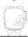
- the figure 1 schematically shows infrared vision binoculars 1.
- Binoculars 1 comprise a housing 2, an optical system 3, an infrared detector 4, a processing module 5 and two display screens 6.
- the optical system 3 has an optical axis Y.
- the optical system 3 is arranged to transmit infrared radiation emitted by a target to the detection module 4.
- the detection module 4 converts the infrared radiation received into a detection signal which is transmitted to the processing module 5.
- the detection module processing 5 controls the display of an image on the screens display 6 to allow a user to view the target. To this end, the user positions his eyes in front of the display screens 6.
- the binoculars also include a cooling device 8.
- the term “cooling device” is to be interpreted as any thermal machine configured to produce cold (such as a cold machine, a cooler, a micro -cooler, etc.).
- the function of the cooling device is to maintain the temperature of the infrared detector at a very low temperature, of the order of 80 degrees Kelvin.
- the cooling device 8 comprises a compression cylinder 10 having a central axis X, and a compression piston 12 movable in translation along the X axis in the compression cylinder 10.
- the compression chamber 13 is defined by the compression cylinder 10 and the compression piston 12.
- the function of the compression piston 12, when it is moved in translation, is to compress or expand a gas located in the compression chamber 13.
- the cooling device 8 further comprises a regeneration cylinder 14 having the Y axis as its central axis and a regenerator piston 16 movable in translation along the Y axis in the regeneration cylinder 14.
- the regeneration cylinder 14 is for example formed. in a cold finger.
- Optical system 3, detector 4 and cold finger 14 are coaxial and arranged in that order along the Y axis.
- the expansion chamber 17 is defined by the regeneration cylinder 14 and the regenerator piston 16.
- the function of the regenerator piston 16, when it is moved in translation in the cylinder, is to compress or expand a gas located in the chamber d. expansion 17.
- the cooling device 8 comprises a pipe 18 connecting the compression chamber 13 to the expansion chamber 17.
- the cooling device 8 further comprises a regenerator 20, arranged in the expansion chamber 17.
- the regenerator 20 is a hollow body suitable for storing part of the heat energy of a gas which passes through it, when the piston of compression 12 compresses the gas in the compression chamber 13 and then restores this energy during a gas expansion in the expansion chamber 17, caused by a movement of the regenerator piston 16.
- Regenerator piston 16 is attached to regenerator 20, or forms part of regenerator 20.
- the compression piston 12 is called a "hot” piston and the regenerator piston is called a “cold” piston. These two names, well known to those skilled in the art, refer to the fact that the gas in the compression chamber 13 is hotter than in the expansion chamber 17.
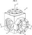
- the cooling device 8 comprises a casing 22 defining a central cavity 24.
- the compression cylinder 10 opens into the central cavity 24.
- the compression cylinder 10 is at least partly formed by the housing 22.
- the regeneration cylinder 14 opens into the central cavity 24, and is partly formed by the housing. 22.
- the pipe 18 connects the compression chamber 13 to the expansion chamber 17 without passing through the central cavity 24.
- the housing 22 defines an access passage 26 to the central cavity 24, which extends along a third axis Z.
- the axes X, Y, Z are orthogonal two by two. They pass through the same central point which is located in the central cavity defined by the housing 22.
- the cooling device 8 comprises a crank 28 configured to be driven in rotation about the Z axis.
- Crank 28 is rotated by a motor, for example an electric motor (not shown in the figures).
- the motor is typically arranged outside the central cavity 24, in a part of the generator located between the processing module 5 and the central cavity 24, this part being visible on the figure 1 .
- the crank 28 comprises a motor shaft 30 extending into the access passage 26 to the central cavity 24.
- a first end of the motor shaft 30 is rotatably mounted on the motor.
- the motor shaft 30 is movable in rotation about the Z axis.
- the motor shaft 30 has, for example, a circular end surface.
- the crank 28 further comprises a crank pin 32 fixed to the end of the motor shaft closest to the central cavity 24.
- the crank pin 32 has a shape of revolution about an axis Z 'parallel to the axis Z , but at a distance from it. The crank pin 32 is therefore caused to move in orbit around the Z axis, during the rotation of the motor shaft 30.
- the crank pin 32 is located in the central cavity 24.
- the crank pin 32 has a typically cylindrical outer surface of revolution.
- the cooling device 8 further comprises a coupling member 34 rotatably mounted on the crank 28.
- the coupling member is rotatably mounted on the crank pin 32 of the crank 28 about the axis Z '.
- the coupling member 34 has a radially internal surface 36.
- the radially internal surface 36 defines an internal space in which the crank pin 32 is received.
- the coupling member 34 therefore extends around the axis of the crank pin 32.
- the inner diameter of the radially inner surface 36 of the coupling member 34 is larger than the outer diameter of the crankpin 32, so that an annular gap 38 is formed between the outer surface of the crankpin 32 and the inner surface 36 of the crankpin 32. organ 34.
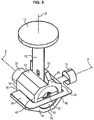
- a system of ball bearings 40 is arranged in this annular gap 36.
- the coupling member 34 comprises a first wall 42 and a second wall 44.
- the crank pin 32 extends between the first wall 42 and the second wall 44.
- the coupling member 34 further comprises a third wall 46 and a fourth wall 48.
- the crank pin 32 extends between the third wall 46 and the fourth wall 48.
- the third wall 46 and the fourth wall 48 each connect the first wall 42 to the second wall 44.
- the four walls 42, 44, 46, 48 together go around the crankpin 32 around its axis Z '.
- the coupling member 34 comprises a first free edge 50 facing the compression piston 12, and a second free edge 52 opposite the first edge 50 relative to the crank pin 32.
- the first free edge 50 is formed in the first wall 42, and the second free edge 52 is formed in the second wall 44.
- the coupling member 34 comprises a third edge 54 facing the regenerator piston 16, and a fourth edge 56 opposite the third edge 54 with respect to the crank pin 32.
- the third free edge 54 is formed in the third wall 46, and the fourth free edge 56 is formed in the fourth wall 48.
- the third free edge 54 and the fourth free edge 56 each connect the first edge 50 to the second edge 52.
- the four free edges 50, 52, 54, 56 together form a portion of the outer surface of the coupling member 34, closed on itself and extending around the crank pin 32.
- the four edges 50, 52, 54, 56 define four sides of the coupling member 34 seen in a section plane perpendicular to the motor axis Z.
- the coupling member 34 also has a fifth edge 58 facing the motor shaft 30, and a sixth edge 60 opposite to the fifth edge 58.
- the fifth edge 58 and the sixth edge 60 each connect the inner surface to the outer surface of the coupling member 34.
- the cooling device comprises a first deformable element 62 configured to transmit to the compression piston 12, while deforming, a reciprocating translational movement undergone by the coupling member 34 when the crank 28 is set in continuous rotation relative to the housing 22 around the Z axis.
- the cooling device also comprises a second deformable element 64 configured to transmit to the regenerator piston 16, while deforming, an alternating translational movement undergone by the coupling member 34 when the crank 28 is set in continuous rotation with respect to the housing 22.
- the first deformable element 62 has a first end portion 66 embedded in the coupling member 34, and a second end portion 68 opposite to the first end portion 66, embedded in the compression piston 12.
- the first deformable element 62 also has an intermediate portion 70 connecting the first end portion 66 to the second end portion 68.
- the first deformable element 62 is a sheet.
- sheet is meant in the present text that the first deformable element 62 has a fine thickness compared to its length and its width.
- the first deformable element 62 is substantially flat.
- the first deformable element 62 has two opposite faces 72 and 74, the thickness of the first deformable element 62 being measured perpendicular to the two faces.
- the two opposite faces 72 and 74 are planar.
- the first deformable element 62 then has a rectilinear profile in a plane perpendicular to the two flat faces (up to the thickness of the first deformable element 62).
- the two flat faces 72, 74 are rectangular.
- a first orifice 76 is formed in the first end portion 66, and a second orifice 78 is formed in the second end portion 68.
- the two orifices 76, 78 each open into the two opposite faces 72 and 74.
- the first deformable element 62 is embedded in the compression piston 12 and in the coupling member 34 such that there is at least one position of the coupling member 34 relative to the housing 22, during one revolution. the crank 28, in which the first deformable element 62 is in its undeformed configuration.
- the first deformable element 62 is of suitable flexibility to allow it to adopt an S-shaped profile in a plane perpendicular to the motor axis, when the axis of the crankpin 32 is not in the plane defined by the 'motor Z axis and compression X axis, as can be seen on the figure 7 .
- the first deformable element 62 has an axial rigidity (measured parallel to the X axis) adapted to allow it to transmit a movement of reciprocating translation of the crank pin 32 to the compression piston 12, even when it is deformed and it has this S shape.
- first edge 50 of the coupling member 34 located opposite the compression piston 12
- first end portion of the first deformable element 62 is fixed, and only to the latter.
- the first deformable element 62 is located between the compression piston 12 and the crank pin 32 of the crank 28, regardless of the position of the crank pin 32 relative to the housing 22.
- the first orifice 76 is aligned with an orifice formed in an element of the coupling member projecting from the first wall towards the compression piston 12.
- a wedge 80 having another port is positioned so that its port is aligned with the ports, and so that the first end portion 76 is sandwiched between the protruding member and the wedge.
- a screw-nut system 82 is used to embed the first portion of the first deformable element 62 in the coupling member 34. This system comprises a screw which is passed through the three holes. The nut cooperates with the screw so as to hold the latter through the three holes.
- the second port 78 is aligned with a port in a member protruding from the compression piston 12 towards the first wall of the coupling member 34.
- a shim 84 having another port is positioned so that its port is aligned. with the orifices, and so that the second end portion 68 is sandwiched between the protruding member of the piston 12 and the shim 84.
- a screw-nut system 86 is used to embed the second end portion of the piston. first deformable element 62 to the coupling member 34. This system comprises a screw which is passed through the three holes. The nut cooperates with the screw so as to hold the latter through the three holes.
- the first deformable element 62 is for example made of blue gauge sheet metal.
- This name known to those skilled in the art, covers in particular the non-alloy structural steel XC70. This steel has the advantage of having good elastic strength (around 1080 MPa) useful for the mechanical strength of the first deformable element 62.
- the blue gauge sheet has the advantage of having a very high elastic limit, as well as an excellent fatigue limit, while having a low Young's modulus so as not to require too much effort during its deformation.
- the use of such a material to produce the first deformable element 62 is therefore particularly advantageous.
- the first deformable element 62 has a thickness of 0.25 millimeters, a length of 15 millimeters, and a width of 6.25 millimeters.
- the Young's modulus of the first deformable element 62 along the compression axis is preferably 210,000 MPa.
- the first deformable element is typically manufactured by chemical cutting.
- the second deformable element 64 has a first end portion 88 embedded in the coupling member 34, and a second end portion 90 opposite the first end 88, embedded in the regenerator piston 16.
- the second deformable element 64 has two opposite faces 92, 94, the thickness of the deformable element 64, measured perpendicularly to the two faces 92, 94 is small in comparison with its length and its width.
- the second deformable element 64 is embedded in the regenerator piston 16 and in the coupling member 34 so that there is at least one position of the coupling member 34 relative to the housing 22, during one revolution of the crank 28, in which the second deformable element 64 is in an undeformed configuration.
- the second deformable element 64 is of suitable flexibility to allow it to adopt an S-shaped profile in a plane perpendicular to the motor axis Z, when the axis of the crank pin 32 is not in the plane defined by the Z motor axis and the Y regeneration axis.
- the second deformable element 64 has an axial rigidity (measured parallel to the regeneration axis Y) which is adapted to allow it to transmit an alternating translational movement from the crank pin 32 to the regenerator piston 16, even when it is deformed and that it has this form of S.
- the second deformable element 64 is for example made of the same material as the other deformable element, for the same reasons.
- the second deformable element 64 is for example produced by chemical cutting. This method has the advantage of being inexpensive and particularly suitable for thin and relatively fragile parts.
- the second deformable element 64 is a sheet.
- the second deformable element 64 has a thickness of 0.25 millimeters, a length of 15 millimeters, and a width of 6.25 millimeters.
- the Young's modulus of the deformable element along the compression axis is preferably 210,000 MPa.
- the shape of the second deformable element 64 is different from that of the first deformable element 62, and the place of embedding of the second deformable element 64 in the coupling member 34 is also different from that of the first deformable element 62.
- the second deformable element 64 has a shape adapted to bypass the coupling member 34 and the crank pin 32.
- the two opposite faces 92 and 94 are not rectangular.
- the coupling member 34 is located between the second portion and the motor shaft 30.
- the bypass of the coupling member 34 by the deformable element is thus facilitated since this deformable element is not hampered by the motor shaft 30 during one revolution of the crank 28.
- the second deformable element 64 comprises, at the junction between the portions 96 and 98, a fillet and / or a rounding.
- the second deformable element 64 furthermore comprises, at the junction between the portions 98 and 100, a fillet and / or a rounding.
- the second deformable element 64 furthermore comprises, at the junction between the portions 100 and 90, a fillet and / or a rounding.
- Each rounding or fillet has the effect of avoiding the concentration of stresses in the second deformable element 64, when the latter is deformed in bending.
- the first end portion 88 of the first deformable element 62 has an orifice 102
- the second end portion 90 has an orifice 104.
- the orifices 102, 104 each open into the two opposite faces 92 and 94.
- the first orifice 102 can be aligned with a nut 108 formed in an element of the coupling member projecting from the fourth wall 48.
- This nut is formed by a tapped hole in this element.
- a screw 106 is passed through the aligned hole 102 and nut 108.
- the nut 108 and the screw 106 are arranged so that the screwing axis of the screw in the nut is parallel to the motor axis Z of the crank 28 and is oriented so that the screw can be screwed in. in the nut by means of a screwing tool introduced into the access passage 26 to the central cavity 24.
- a screwing tool introduced into the access passage 26 to the central cavity 24.
- Such an arrangement makes it easier to remove and replace the second deformable element 64.
- the first portion of end 88 is bent at 90 degrees relative to the intermediate portion 96.
- other means for embedding the second deformable element 68 in the coupling member 34 can be used instead of the orifice 10 and of a screw-nut system.
- the second intermediate portion is inserted into a gap formed between the element in which the nut is formed and another element protruding from the fourth wall of the coupling member 34, as shown in figure figure 10 .
- the second orifice 104 of the second deformable element is moreover engaged in a groove formed in the regenerator piston 16, so that this orifice 104 is arranged between and aligned with two transverse orifices opening into the groove (typically with a diameter of 0.6 mm ).
- a pin is passed through the three aligned holes, to embed the second deformable element 64 in the regenerator piston 16.
- other means for embedding the second deformable element 68 in the regenerator piston 16 can be used, for example by gluing. without resorting to a pin.
- the means for moving the pistons 12 and 16 are mounted in the cooling device 8 according to the following method.
- the second deformable member 64 is embedded in the regenerator piston 16, and the regenerator piston 16 is attached to the regenerator 20, so as to form a first set of parts.
- the first deformable element 62 is fitted to the coupling member 34 and to the compression piston 12, so as to form a second set of parts.
- the two sets of parts are assembled by fitting the second deformable element 64 to the coupling member 34.
- the motor shaft 30 is inserted through the access passage 26 to the cavity 24 so that the crank pin 32 engages the coupling piece 34.
- the cooling device 8 operates as follows.
- crank pin 32 itself rotates around the Z axis, being integral with the motor shaft 30 , as well as the coupling member 34 extending around the crankpin 30.
- the coupling member 32 drives with it the first deformable element 62, so that the latter moves the compression piston 12 in rectilinear translation along the X axis, while being deformed in bending.
- the coupling member 32 drives with it the second deformable element 64, so that the latter moves the regeneration piston 16 in rectilinear translation along the Y axis, while being deformed in bending.
- the second deformable element 64 is longer than if it had been embedded in the first edge 50 of the coupling member 34, opposite the regenerator piston 12. Thanks to this excess length, the deformable element 64 is slightly flexed during one revolution of the crank 28, which slows down its wear.
- the coupling member undergoes a slight reciprocating rotational movement with respect to the housing 22.
- This rotation is limited by the axial rigidity of the two deformable elements 62 and 64. Consequently, the edge 50 of the coupling member 34 remains constantly facing the compression piston 12, and the edge 54 of the coupling member 34 remains constantly facing the regenerator piston 16, during one revolution of the crank 28.
- the figure 12 shows for example a second embodiment of a cooling device differing from the first embodiment in that the second deformable element 64 bypassing the coupling member 34 is replaced by a deformable element 65 passing through the body of the cutting member 34.
- the second deformable element 65 extends in particular across a passage formed in the third wall 46 (the one closest to and facing the regenerator piston 16, and in which the edge 54 is formed), and moreover in through another passage formed in the fourth wall 48 opposite to the wall 46 (and in which the edge 56 is formed).
- the figure 13 shows a third embodiment of the cooling device which differs from the first embodiment by the following characteristics relating to the fitting of the deformable element 64 to the coupling member 34.
- the end portion 88 of the element deformable 64 is not bent at 90 degrees relative to the rest of the deformable element 64.
- the wedge 80 is replaced by two wedge elements 81, 83.
- the screw 106 passes through the first wedge element 81 then the 'nut 108 formed in the coupling member 34.
- the second wedge member 83 is arranged to rest against the end portion 88 of the deformable member 64.
- the two wedge members 81 and 83 are shaped so that they 'screwing the screw parallel to the motor axis Z causes the first shim element 81 to be stressed on the second shim element along an axis perpendicular to the Z axis (and parallel to the X axis), and by way consequently, a stress on the second wedge element 83 against the end portion of the deformable element 64.
- Such a bias can be obtained by giving the two wedge elements a bevelled shape.
Landscapes
- Engineering & Computer Science (AREA)
- General Engineering & Computer Science (AREA)
- Physics & Mathematics (AREA)
- Mechanical Engineering (AREA)
- Thermal Sciences (AREA)
- General Physics & Mathematics (AREA)
- Spectroscopy & Molecular Physics (AREA)
- Astronomy & Astrophysics (AREA)
- Optics & Photonics (AREA)
- Chemical & Material Sciences (AREA)
- Combustion & Propulsion (AREA)
- Transmission Devices (AREA)
- Compressors, Vaccum Pumps And Other Relevant Systems (AREA)
- Compressor (AREA)
Description
- La présente invention concerne un dispositif de refroidissement.
- Ce dispositif de refroidissement trouve avantageusement application dans un dispositif de vision infrarouge.
- On connait des équipements de vision infrarouge, tels que des jumelles par exemple, qui permettent de visualiser des cibles la nuit ou à travers des fumées.
- De tels équipements de vision infrarouge comprennent un détecteur infrarouge et un dispositif de refroidissement (également appelé machine à froid ou micro-refroidisseur), assurant le refroidissement du détecteur infrarouge, à une température typiquement de l'ordre de 80 degrés Kelvin.
- Un dispositif de refroidissement pour équipement de vision infrarouge connu, de type Stirling alpha, comprend un carter, une manivelle mobile en rotation par rapport au carter, un organe de couplage monté à rotation sur la manivelle, et deux pistons : un piston de compression de gaz, conventionnellement nommé piston « chaud », et un piston régénérateur, conventionnellement nommé piston « froid » par contraste avec le piston chaud.
- Une transformation d'un mouvement de rotation continu de la manivelle par rapport au carter en un mouvement alternatif de translation de chacun des deux pistons par rapport au carter est mise en oeuvre au moyen de deux bielles. Chaque bielle est montée à rotation sur la pièce de couplage d'une part et l'un des pistons d'autre part, de sorte à former un système bielle-manivelle classique.
- Les bielles présentent cependant comme inconvénient de causer un bruit phonique important dans l'équipement de vision infrarouge. Ce bruit est causé par des vibrations engendrées par des chocs de rattrapage de jeu au niveau des deux liaisons pivot que chaque bielle forme avec d'une part l'un des deux pistons et d'autre part avec l'organe de couplage, lorsque des directions d'effort changent. Ce bruit est désagréable pour un utilisateur de l'équipement de vision infrarouge. Par ailleurs, un équipement de vision infrarouge a souvent vocation à être utilisée dans des missions demandant une grande discrétion. Or, un utilisateur de l'équipement de vision infrarouge pourrait être repéré à cause du bruit phonique important causé par la bielle de cet équipement. Pour éviter à ce problème de bruit phonique, il est nécessaire de réduire les jeux des liaisons pivot à quelques microns. Ceci augmente toutefois le coût de fabrication du dispositif de refroidissement.
- Un autre inconvénient de la bielle est que les deux liaisons pivot peuvent s'user ou se gripper. Pour éviter ces problèmes, il est nécessaire d'avoir une maîtrise parfaite sur les paramètres de tribologie relatifs à la bielle et les deux pièces sur lesquelles elle est montée à rotation pour former les deux liaisons pivot (lubrification, dureté, état de surface, etc.). Or, ces exigences ne peuvent pas être remplies sans augmenter le coût de fabrication du dispositif de refroidissement.
- Pour s'affranchir de ces problèmes sans pour autant augmenter le coût de fabrication du dispositif de refroidissement, il a été proposé de remplacer la bielle déplaçant le piston de compression par un élément déformable. L'élément déformable est encastré d'une part au piston et d'autre part à un bord de l'organe de couplage qui se trouve en regard du piston. L'élément déformable s'étend dans son entièreté entre l'organe de couplage et le piston de compression. Lorsque la manivelle est mise en rotation continue par rapport au carter, l'élément déformable transmet au piston, tout en se déformant, le mouvement de translation alternatif subi par l'organe de couplage. En remplaçant une des bielles par l'élément déformable, on supprime dans le dispositif de refroidissement au moins une liaison pivot génératrice de bruit phonique.
- Or, un dispositif de refroidissement pour équipement à vision infrarouge se doit d'être le plus compact possible. Pour respecter cette exigence de compacité, la distance séparant le piston et l'organe de couplage est faible comparativement à la course du piston. Ceci a pour conséquence que l'élément déformable qui s'étend entre le piston et cet organe est fortement sollicité en flexion au cours d'un tour de manivelle, ce qui le fatigue de manière importante.
- Il a été proposé dans le document
FR3033630 - Cependant, l'élément déformable décrit dans le document
FR3033630 EP0339836 divulgue un dispositif de refroidissement selon le préambule de la revendication 1. Z - Un but de l'invention est de proposer un dispositif de refroidissement plus résistant à l'usure, tout en étant de fabrication peu coûteuse, et générant un bruit phonique réduit sans augmenter significativement son encombrement.
- Il est ainsi proposé, selon un premier aspect de l'invention, un dispositif de refroidissement comprenant :
- un carter,
- une manivelle mobile en rotation par rapport au carter,
- un piston,
- un organe de couplage monté à rotation sur la manivelle, l'organe de couplage présentant un premier bord en regard du piston et un deuxième bord opposé au premier bord,
- un élément déformable encastré à l'organe de couplage et encastré au piston, l'élément déformable étant configuré pour déplacer le piston en translation par rapport au carter tout en se déformant, lorsque la manivelle est mise en rotation par rapport au carter, l'élément déformable étant encastré au deuxième bord de l'organe de couplage.
- Comme le premier bord de l'organe de couplage est en regard du piston et que le deuxième bord est opposé au premier bord, le deuxième bord est plus éloigné du piston que le premier bord. En conséquence, l'élément déformable est plus long que s'il était encastré au premier côté de l'organe de couplage, comme cela est proposé dans l'état de la technique. Grâce à cette surlongueur, l'élément déformable est comparativement moins fléchi au cours d'un tour de la manivelle. Et comme l'élément déformable est moins sollicité en flexion, sa fatigue est amoindrie. Cette surlongueur de l'élément déformable est obtenue sans avoir à augmenter la distance entre le piston et la manivelle. La dimension du dispositif de refroidissement parallèlement à l'axe de translation du piston n'est donc pas augmentée de manière significative.
- De plus, l'élément déformable comprend :
- une première portion s'étendant le long du deuxième bord de l'organe parallèlement à un axe de rotation de la manivelle,
- une deuxième portion prolongeant la première portion et s'étendant vers le piston,
- une troisième portion prolongeant la deuxième portion et s'étendant parallèlement à l'axe de rotation de la manivelle, de sorte que les trois portions forment un U chevauchant l'organe de couplage.
- Cette forme particulière d'élément déformable a pour avantage de ne pas requérir une augmentation significative d'une dimension du dispositif de refroidissement suivant une direction perpendiculaire à l'axe de translation du piston.
- Un autre avantage procuré par cette forme particulière d'élément déformable est qu'elle est facilement adaptable à dispositifs de refroidissement existants dans lesquels l'axe de translation du piston et l'axe de rotation de la manivelle sont coplanaires.
- Le dispositif de refroidissement peut comprendre en outre les caractéristiques optionnelles suivantes, prises seules ou en combinaison lorsque cela est techniquement possible.
- L'élément déformable peut présenter une forme adaptée pour contourner l'organe de couplage sans toucher le premier bord au cours de la rotation de la manivelle par rapport au carter.
- Il peut en outre être prévu que :
- la manivelle comprenne un arbre moteur et un maneton excentré par rapport à l'arbre moteur,
- l'organe de couplage soit monté à rotation sur le maneton, et soit localisé entre la deuxième portion de l'organe de couplage et l'arbre moteur.
- L'élément déformable peut présenter un arrondi et/ou un congé en au moins une jonction entre deux des portions.
- La manivelle peut comprendre un maneton, et l'organe de couplage comprendre une première paroi dans laquelle le premier bord est formé et une deuxième paroi dans laquelle le deuxième bord est formé, le maneton étant agencé entre les deux parois.
- L'élément déformable peut être réalisé en métal.
- L'élément déformable peut être une tôle, voire une tôle bleue à calibres.
- L'élément déformable peut comprendre une portion d'extrémité présentant un premier orifice, et le piston présenter : une rainure pour recevoir la portion d'extrémité, deux orifices débouchant dans la rainure et agencés pour être alignés avec le premier orifice, et une goupille passée à travers les trois orifices alignés pour encastrer l'élément déformable au piston.
- Le dispositif de refroidissement peut en outre comprendre
- un écrou formé dans l'organe de couplage,
- une vis propre à coopérer avec l'élément déformable et l'écrou de sorte à encastrer l'élément déformable à l'organe de couplage.
- Par ailleurs, le carter peut définir une cavité logeant l'organe de couplage, et présente par ailleurs un passage d'accès à la cavité, et l'écrou peut être orienté en regard du passage d'accès de sorte que la vis puisse être vissée dans l'écrou au moyen d'un outil de vissage introduit dans la cavité via le passage d'accès.
- Le dispositif de refroidissement peut être du type Stirling alpha, auquel cas le piston peut être un piston froid du dispositif de refroidissement.
- Le dispositif de refroidissement peut comprendre en outre :
- un deuxième piston,
- un deuxième élément déformable encastré à l'organe de couplage et encastré au deuxième piston, le deuxième élément déformable étant configuré pour déplacer le deuxième piston en translation par rapport au carter tout en se déformant, lorsque la manivelle est mise en rotation par rapport au carter.
- L'organe de couplage peut présenter également un troisième bord en regard du deuxième piston, dans lequel le deuxième élément déformable est encastré au troisième bord de l'organe de couplage.
- Lorsque le dispositif de refroidissement est de type Stirling alpha, le deuxième piston peut être un piston chaud du dispositif de refroidissement.
- Le dispositif de refroidissement peut être tout particulièrement destiné à être embarqué dans un dispositif de vision infrarouge.
- Selon un deuxième aspect de l'invention, il est proposé un dispositif de vision infrarouge, par exemple des jumelles, comprenant un dispositif de refroidissement conforme au premier aspect de l'invention.
- D'autres caractéristiques, buts et avantages de l'invention ressortiront de la description qui suit, qui est purement illustrative et non limitative, et qui doit être lue en regard des dessins annexés sur lesquels :
- La
figure 1 est une vue schématique de jumelles à vision infrarouge, selon un mode de réalisation de l'invention. - La
figure 2 est une vue en coupe partielle d'un dispositif de refroidissement, selon un mode de réalisation de l'invention. - La
figure 3 est une vue en perspective d'un carter d'un dispositif de refroidissement selon un mode de réalisation de l'invention. - La
figure 4 est une vue partielle en coupe et en perspective d'un dispositif de refroidissement selon un premier mode de réalisation de l'invention. - La
figure 5 est une vue en perspective de certaines pièces du dispositif de refroidissement selon le premier mode de réalisation. - Les
figures 6 et 7 sont deux vues en perspectives d'un premier élément déformable du dispositif de refroidissement selon le premier mode de réalisation, respectivement dans un état non-déformé et dans un état déformé. - La
figure 8 est une vue en perspective du premier élément déformable représenté sur lesfigures 6 et 7 et d'autres pièces du dispositif de refroidissement auxquelles cet élément déformable est encastré. - La
figure 9 est une vue en perspective d'un deuxième élément déformable du dispositif de refroidissement selon le premier mode de réalisation. - La
figure 10 est une vue partielle en perspective du deuxième élément déformable représenté sur lafigure 9 et d'un organe de couplage du dispositif de refroidissement de lafigure 5 . - La
figure 11 est une vue partielle en coupe en perspective du deuxième élément déformable représenté sur lafigure 9 et d'un piston du dispositif de refroidissement de lafigure 5 . - La
figure 12 est une vue en perspective de certaines pièces d'un dispositif de refroidissement selon un deuxième mode de réalisation de l'invention. - La
figure 13 est une vue en perspective de certaines pièces d'un dispositif de refroidissement selon un troisième mode de réalisation de l'invention. - Sur l'ensemble des figures, les éléments similaires portent des références identiques.
- La
figure 1 représente de manière schématique des jumelles de vision infrarouge 1. Les jumelles 1 comprennent un boîtier 2, un système optique 3, un détecteur infrarouge 4, un module de traitement 5 et deux écrans d'affichage 6. Le système optique 3 présente un axe optique Y. Le système optique 3 est agencé pour transmettre un rayonnement infrarouge émis par une cible au module de détection 4. Le module de détection 4 convertit le rayonnement infrarouge reçu en un signal de détection qui est transmis au module de traitement 5. Le module de traitement 5 commande l'affichage d'une image sur les écrans d'affichage 6 pour permettre à un utilisateur de visualiser la cible. A cet effet, l'utilisateur positionne ses yeux en face des écrans d'affichage 6. - Les jumelles comprennent par ailleurs un dispositif de refroidissement 8. Dans le présent texte, le terme de « dispositif de refroidissement » est à interpréter comme toute machine thermique configurée pour produire du froid (telle qu'une machine à froid, un refroidisseur, un micro-refroidisseur, etc.). Le dispositif de refroidissement a pour fonction de maintenir la température du détecteur infrarouge, à une température très basse, de l'ordre de 80 degrés Kelvin.
- En référence à la
figure 2 , le dispositif de refroidissement 8 selon un premier mode de réalisation comprend un cylindre de compression 10 ayant un axe central X, et un piston de compression 12 mobile en translation suivant l'axe X dans le cylindre de compression 10. La chambre de compression 13 est définie par le cylindre de compression 10 et le piston de compression 12. - Le piston de compression 12 a pour fonction, lorsqu'il est déplacé en translation, de comprimer ou détendre un gaz se trouvant dans la chambre de compression 13.
- Le dispositif de refroidissement 8 comprend en outre un cylindre de régénération 14 présentant comme axe central l'axe Y et un piston régénérateur 16 mobile en translation suivant l'axe Y dans le cylindre de régénération 14. Le cylindre de régénération 14 est par exemple formé dans un doigt froid.
- Le système optique 3, le détecteur 4 et le doigt froid 14 sont coaxiaux et agencés dans cet ordre le long de l'axe Y.
- La chambre d'expansion 17 est définie par le cylindre de régénération 14 et le piston régénérateur 16. Le piston régénérateur 16 a pour fonction, lorsqu'il est déplacé en translation dans le cylindre de comprimer ou détendre un gaz se trouvant dans la chambre d'expansion 17.
- Le dispositif de refroidissement 8 comprend une canalisation 18 reliant la chambre de compression 13 à la chambre d'expansion 17.
- Le dispositif de refroidissement 8 comprend par ailleurs un régénérateur 20, agencé dans la chambre d'expansion 17. Le régénérateur 20 est un corps creux adapté pour stocker une partie de l'énergie calorifique d'un gaz qui le traverse, lorsque le piston de compression 12 comprime le gaz se trouvant dans la chambre de compression 13 et de restituer ensuite cette énergie lors d'une détente de gaz dans la chambre d'expansion 17, provoquée par un déplacement du piston régénérateur 16.
- Le piston régénérateur 16 est fixé au régénérateur 20, ou forme une partie du régénérateur 20.
- Le dispositif de refroidissement 8 est de type Stirling alpha. A titre de rappel, un cycle de Stirling comprend quatre phases :
- Une phase de compression isotherme, au cours de laquelle du gaz se trouvant dans la chambre de compression 13 est comprimé par le piston de compression 12 s'éloignant de la cavité centrale.
- Une phase de refroidissement isochore, au cours de laquelle le gaz comprimé est transféré de la chambre de compression 13 vers la chambre d'expansion 17 via la canalisation 18. Le gaz cède une partie de son énergie calorifique au régénérateur 20, lorsqu'il le traverse. La baisse de température qui est alors provoquée entraîne une chute de pression.
- Une phase de détente isotherme, au cours de laquelle engendrée par un déplacement du piston régénérateur 16 vers la cavité centrale. La chute de pression entraîne le refroidissement du gaz contenu dans la chambre d'expansion 17.
- Une phase de réchauffement isochore, au cours de laquelle le gaz passe de la chambre d'expansion 17 vers la chambre de compression 13, via la canalisation 18. En traversant le régénérateur 20, le gaz récupère la chaleur qu'il a cédée durant la phase de refroidissement isochore.
- Le piston de compression 12 est appelé piston « chaud » et le piston régénérateur est appelé piston « froid ». Ces deux appellations, bien connues de l'homme du métier, font référence au fait que le gaz dans la chambre de compression 13 est plus chaud que dans la chambre d'expansion 17.
- On va maintenant détailler les moyens de déplacement des pistons 12 et 16 qui permettent de mettre en œuvre ce cycle de Stirling.
- En référence à la
figure 3 , le dispositif de refroidissement 8 comprend un carter 22 définissant une cavité centrale 24. - Le cylindre de compression 10 débouche dans la cavité centrale 24. Le cylindre de compression 10 est au moins en partie formé par le carter 22. Similairement, le cylindre de régénération 14 débouche dans la cavité centrale 24, et est en partie formé par le carter 22.
- En revanche, la canalisation 18 relie la chambre de compression 13 à la chambre d'expansion 17 sans passer par la cavité centrale 24.
- Le carter 22 définit un passage d'accès 26 à la cavité centrale 24, lequel s'étend le long d'un troisième axe Z. Les axes X, Y, Z sont orthogonaux deux à deux. Ils passent par un même point central qui se trouve dans la cavité centrale définie par le carter 22.
- En référence à la
figure 4 , le dispositif de refroidissement 8 comprend une manivelle 28 configurée pour être entraînée en rotation autour de l'axe Z. - La manivelle 28 est entraînée en rotation par un moteur, par exemple un moteur électrique (non représenté sur les figures). Le moteur est typiquement agencé à l'extérieur de la cavité centrale 24, dans une partie du générateur se trouvant entre le module de traitement 5 et la cavité centrale 24, cette partie étant visible sur la
figure 1 . - La manivelle 28 comprend un arbre moteur 30 s'étendant dans le passage d'accès 26 à la cavité centrale 24.
- Une première extrémité de l'arbre moteur 30 est montée à rotation sur le moteur. Une deuxième extrémité de l'arbre moteur 30, opposée à la première extrémité, s'étend dans la cavité centrale 24 ou à proximité de celle-ci.
- L'arbre moteur 30 est mobile en rotation autour de l'axe Z. L'arbre moteur 30 présente par exemple une surface d'extrémité circulaire.
- La manivelle 28 comprend en outre un maneton 32 fixé à l'extrémité de l'arbre de moteur la plus proche de la cavité centrale 24. Le maneton 32 présente une forme de révolution autour d'un axe Z' parallèle à l'axe Z, mais à distance de celui-ci. Le maneton 32 est donc amené à se déplacer en orbite autour de l'axe Z, au cours de la rotation de l'arbre moteur 30.
- Le maneton 32 se trouve dans la cavité centrale 24. Le maneton 32 présente une surface externe typiquement cylindrique de révolution.
- Le dispositif de refroidissement 8 comprend en outre un organe de couplage 34 monté à rotation sur la manivelle 28.
- Plus précisément, l'organe de couplage est monté à rotation sur le maneton 32 de la manivelle 28 autour de l'axe Z'.
- L'organe de couplage 34 présente une surface radialement interne 36. La surface radialement interne 36 définit un espace interne dans lequel le maneton 32 est reçu. L'organe de couplage 34 s'étend donc autour de l'axe du maneton 32.
- Le diamètre interne de la surface radialement interne 36 de l'organe de couplage 34 est plus grand que le diamètre externe du maneton 32, si bien qu'un interstice annulaire 38 est formé entre la surface externe du maneton 32 et la surface interne 36 de l'organe 34.
- En référence à la
figure 5 , un système de roulements à billes 40 est agencé dans cet interstice annulaire 36. - L'organe de couplage 34 comprend une première paroi 42 et une deuxième paroi 44. Le maneton 32 s'étend entre la première paroi 42 et la deuxième paroi 44.
- L'organe de couplage 34 comprend en outre une troisième paroi 46 et une quatrième paroi 48. Le maneton 32 s'étend entre la troisième paroi 46 et la quatrième paroi 48.
- La troisième paroi 46 et la quatrième paroi 48 relient chacune la première paroi 42 à la deuxième paroi 44. Autrement dit, les quatre parois 42, 44, 46, 48 font ensemble le tour du maneton 32 autour de son axe Z'.
- L'organe de couplage 34 comprend un premier bord libre 50 en regard du piston de compression 12, et un deuxième bord libre 52 opposé au premier bord 50 par rapport au maneton 32. Le premier bord libre 50 est formé dans la première paroi 42, et le deuxième bord libre 52 est formé dans la deuxième paroi 44.
- L'organe de couplage 34 comprend un troisième bord 54 en regard du piston régénérateur 16, et un quatrième bord 56 opposé au troisième bord 54 par rapport au maneton 32. Le troisième bord libre 54 est formé dans la troisième paroi 46, et le quatrième bord libre 56 est formé dans la quatrième paroi 48.
- Le troisième bord libre 54 et le quatrième bord libre 56 relient chacune le premier bord 50 au deuxième bord 52.
- Les quatre bords libres 50, 52, 54, 56 forment ensemble une portion de la surface externe de l'organe de couplage 34, fermée sur elle-même et s'étendant autour du maneton 32. Les quatre bords 50, 52, 54, 56 définissent quatre côtés de l'organe de couplage 34 vu dans un plan de coupe perpendiculaire à l'axe moteur Z.
- L'organe de couplage 34 présente en outre un cinquième bord 58 en regard de l'arbre moteur 30, et un sixième bord 60 opposé au cinquième bord 58.
- Le cinquième bord 58 et le sixième bord 60 relient chacun la surface interne à la surface externe de l'organe de couplage 34.
- Le dispositif de refroidissement comprend un premier élément déformable 62 configuré pour transmettre au piston de compression 12, tout en se déformant, un mouvement de translation alternatif subi par l'organe de couplage 34 lorsque la manivelle 28 est mise en rotation continue par rapport au carter 22 autour de l'axe Z.
- Le dispositif de refroidissement comprend par ailleurs un deuxième élément déformable 64 configuré pour transmettre au piston régénérateur 16, tout en se déformant, un mouvement de translation alternatif subi par l'organe de couplage 34 lorsque la manivelle 28 est mise en rotation continue par rapport au carter 22.
- En référence aux
figures 6 et 7 , le premier élément déformable 62 présente une première portion d'extrémité 66 encastrée à l'organe de couplage 34, et une deuxième portion d'extrémité 68 opposée à la première portion d'extrémité 66, encastrée au piston de compression 12. - Le premier élément déformable 62 présente en outre une portion intermédiaire 70 reliant la première portion d'extrémité 66 à la deuxième portion d'extrémité 68.
- Le premier élément déformable 62 est une tôle. Par tôle, on entend dans le présent texte que le premier élément déformable 62 présente une épaisseur fine comparée à sa longueur et sa largeur.
- Dans une configuration non déformée, le premier élément déformable 62 est sensiblement plat.
- Le premier élément déformable 62 présente deux faces opposées 72 et 74, l'épaisseur du premier élément déformable 62 étant mesurée perpendiculairement aux deux faces.
- Dans une configuration non déformée, les deux faces opposées 72 et 74 sont planes. Le premier élément déformable 62 présente alors un profil rectiligne dans un plan perpendiculaire aux deux faces planes (à l'épaisseur du premier élément déformable 62 près).
- Les deux faces planes 72, 74 sont rectangulaires.
- Un premier orifice 76 est formé dans la première portion d'extrémité 66, et un deuxième orifice 78 est formé dans la deuxième portion d'extrémité 68. Les deux orifices 76, 78 débouchent chacun dans les deux faces opposées 72 et 74.
- Le premier élément déformable 62 est encastré au piston de compression 12 et à l'organe de couplage 34 de telle sorte qu'il existe au moins une position de l'organe de couplage 34 relativement au carter 22, au cours d'un tour de la manivelle 28, dans laquelle le premier élément déformable 62 est dans sa configuration non déformée.
- Plus précisément, comme cela est représenté en
figure 6 , le premier élément déformable 62 est encastré au piston de compression 12 et en la surface externe de l'organe de couplage 34 en des positions adaptées pour que le premier élément déformable 62 puisse être traversé sur toute sa longueur par le plan formé par l'axe moteur Z et l'axe de compression X (donc non déformé en flexion) lorsque : - le maneton 32 occupe une position la plus proche du piston de compression 12 au cours d'un tour de la manivelle 28,
- le maneton 32 occupe une position la plus éloignée du piston de compression 12 au cours d'un tour de la manivelle 28.
- Le premier élément déformable 62 est d'une flexibilité adaptée pour lui permettre d'adopter un profil en forme de S dans un plan perpendiculaire à l'axe moteur, lorsque l'axe du maneton 32 n'est pas dans le plan défini par l'axe moteur Z et l'axe de compression X, comme cela est visible sur la
figure 7 . - Néanmoins, le premier élément déformable 62 présente une rigidité axiale (mesurée parallèlement à l'axe X) adaptée pour lui permettre de transmettre un mouvement de translation alternatif du maneton 32 au piston de compression 12, même lorsqu'il est déformé et qu'il a cette forme de S.
- C'est au premier bord 50 de l'organe de couplage 34 (se trouvant en regard du piston de compression 12) que la première portion d'extrémité du premier élément déformable 62 est fixée, et uniquement à celui-ci. Le premier élément déformable 62 est localisé entre le piston de compression 12 et le maneton 32 de la manivelle 28, quelle que soit la position du maneton 32 relativement au carter 22.
- En référence à la
figure 8 , pour encastrer le premier élément déformable 66 à l'organe de couplage 34, le premier orifice 76 est aligné avec un orifice formé dans un élément de l'organe de couplage faisant saillie depuis la première paroi vers le piston de compression 12. Une cale 80 présentant un autre orifice est positionnée de sorte que son orifice soit aligné avec les orifices, et de sorte que la première portion d'extrémité 76 soit prise en sandwich entre l'élément en saillie et la cale. Un système vis-écrou 82 est utilisé pour encastrer la première portion du premier élément déformable 62 à l'organe de couplage 34. Ce système comprend une vis qui est passée à travers les trois orifices. L'écrou coopère avec la vis de sorte à maintenir celle-ci en travers des trois orifices. - Similairement, le deuxième orifice 78 est aligné avec un orifice dans un élément faisant saillie depuis le piston de compression 12 vers la première paroi de l'organe de couplage 34. Une cale 84 présentant un autre orifice est positionnée de sorte que son orifice soit aligné avec les orifices, et de sorte que la deuxième portion d'extrémité 68 soit prise en sandwich entre l'élément en saillie du piston 12 et la cale 84. Un système vis-écrou 86 est utilisé pour encastrer la deuxième portion d'extrémité du premier élément déformable 62 à l'organe de couplage 34. Ce système comprend une vis qui est passée à travers les trois orifices. L'écrou coopère avec la vis de sorte à maintenir celle-ci en travers des trois orifices.
- Le premier élément déformable 62 est par exemple réalisé en tôle bleue à calibres. Cette dénomination, connue de l'homme du métier, couvre notamment l'acier de construction non allié XC70. Cet acier présente l'avantage d'avoir une bonne résistance élastique (environ 1080 MPa) utile pour la tenue mécanique du premier élément déformable 62.
- La tôle bleue à calibres présente l'avantage d'avoir une limite d'élastique très importante, ainsi qu'une excellente limite en fatigue, tout en ayant un faible module Young pour ne pas nécessiter trop d'effort lors de sa déformation. L'emploi d'un tel matériau pour réaliser le premier élément déformable 62 est donc particulièrement avantageux.
- Par exemple, le premier élément déformable 62 présente une épaisseur de 0.25 millimètres, une longueur de 15 millimètres, et une largeur de 6.25 millimètres.
- Par ailleurs, le module d'Young du premier élément déformable 62 suivant l'axe de compression est de préférence de 210000 MPa.
- Le premier élément déformable est typiquement fabriqué par découpe chimique.
- En référence à la
figure 9 , le deuxième élément déformable 64 présente une première portion d'extrémité 88 encastrée à l'organe de couplage 34, et une deuxième portion d'extrémité 90 opposée à la première extrémité 88, encastrée au piston régénérateur 16. - Le deuxième élément 64 déformable présente deux faces 92, 94 opposées, l'épaisseur de l'élément déformable 64, mesurée perpendiculairement aux deux faces 92, 94 est faible en comparaison de sa longueur et de sa largeur.
- Le deuxième élément déformable 64 est encastré au piston régénérateur 16 et à l'organe de couplage 34 de telle sorte qu'il existe au moins une position de l'organe de couplage 34 relativement au carter 22, au cours d'un tour de la manivelle 28, dans laquelle le deuxième élément déformable 64 est dans une configuration non déformée.
- Plus précisément, le deuxième élément déformable 64 est encastré au piston régénérateur 16 et en la surface externe de l'organe de couplage 34 en des positions adaptées pour que l'élément déformable puisse être traversé sur toute sa longueur par le plan formé par l'axe moteur et l'axe de régénération (donc non déformé en flexion) lorsque :
- le maneton 32 occupe une position la plus proche du piston régénérateur 16 au cours d'un tour de la manivelle 28,
- le maneton 32 occupe une position la plus éloignée du piston régénérateur 16 au cours d'un tour de la manivelle 28.
- Le deuxième élément déformable 64 est d'une flexibilité adaptée pour lui permettre d'adopter un profil en forme de S dans un plan perpendiculaire à l'axe moteur Z, lorsque l'axe du maneton 32 n'est pas dans le plan défini par l'axe moteur Z et l'axe de régénération Y.
- Néanmoins, le deuxième élément déformable 64 présente une rigidité axiale (mesurée parallèlement à l'axe de régénération Y) qui est adaptée pour lui permettre de transmettre un mouvement de translation alternatif du maneton 32 au piston régénérateur 16, même lorsqu'il est déformé et qu'il a cette forme de S.
- Le deuxième élément déformable 64 est par exemple réalisé dans le même matériau que l'autre élément déformable, et ce pour les mêmes raisons.
- Le deuxième élément déformable 64 est par exemple réalisé par découpe chimique. Ce procédé présente comme avantage d'être peu coûteux et particulièrement adapté aux pièces de faible épaisseur et relativement fragiles.
- Le deuxième élément déformable 64 est une tôle.
- Par exemple, le deuxième élément déformable 64 présente une épaisseur de 0.25 millimètres, une longueur de 15 millimètres, et une largeur de 6.25 millimètres.
- Par ailleurs, le module d'Young de l'élément déformable suivant l'axe de compression est de préférence de 210000 MPa.
- Toutefois, la forme du deuxième élément déformable 64 est différente de celle du premier élément déformable 62, et le lieu d'encastrement du deuxième élément déformable 64 à l'organe de couplage 34 est également différent de celui du premier élément déformable 62.
- C'est au quatrième bord 56 de l'organe de couplage 34 que la première portion d'extrémité de l'élément déformable est fixée, et uniquement à celle-ci. En particulier, l'élément déformable n'est pas fixé au troisième bord 54 en regard du piston régénérateur 16.
- Le deuxième élément déformable 64 présente une forme adaptée pour contourner l'organe de couplage 34 et le maneton 32.
- En outre, les deux faces opposées 92 et 94 ne sont pas rectangulaires.
- Le deuxième élément déformable 64 présente les portions suivantes (outre ses deux portions d'extrémité 88, 90) :
- une première portion intermédiaire 96 prolongeant la première portion d'extrémité 88, la première portion intermédiaire 96 s'étendant en regard du quatrième bord 56, parallèlement à l'axe moteur Z,
- une deuxième portion intermédiaire 98 prolongeant la première portion intermédiaire 96, en regard du sixième bord 60, et s'étendant vers le piston régénérateur 16, parallèlement à l'axe de régénération Y,
- une troisième portion intermédiaire 100 prolongeant la deuxième portion intermédiaire 98 et s'étendant parallèlement à l'axe moteur Z, de sorte que les trois portions 96, 98, 100 forment ensemble un U chevauchant l'organe de couplage 34.
- Grâce au fait que la deuxième portion intermédiaire 98 est agencée en regard du sixième bord 60, l'organe de couplage 34 se trouve localisé entre la deuxième portion est l'arbre moteur 30. Le contournement de l'organe de couplage 34 par l'élément déformable est ainsi facilité puisque cet élément déformable n'est pas gêné par l'arbre moteur 30 au cours d'un tour de la manivelle 28.
- Le deuxième élément déformable 64 comprend, à la jonction entre les portions 96 et 98, un congé et/ou un arrondi.
- Le deuxième élément déformable 64 comprend par ailleurs, à la jonction entre les portions 98 et 100, un congé et/ou un arrondi.
- Le deuxième élément déformable 64 comprend par ailleurs, à la jonction entre les portions 100 et 90, un congé et/ou un arrondi.
- Chaque arrondi ou congé a pour effet d'éviter la concentration de contraintes dans le deuxième élément déformable 64, lorsque celui-ci est déformé en flexion.
- La première portion 88 d'extrémité du premier élément déformable 62 présente un orifice 102, et la deuxième portion d'extrémité 90 présente un orifice 104. Les orifices 102, 104 débouchent chacun dans les deux faces opposées 92 et 94.
- En référence à la
figure 10 , pour encastrer le deuxième élément déformable 68 à l'organe de couplage 34, le premier orifice 102 peut être aligné avec un écrou 108 formé dans un élément de l'organe de couplage faisant saillie depuis la quatrième paroi 48. Cet écrou est formé par un trou taraudé dans cet élément. Une vis 106 est passée à travers l'orifice 102 et l'écrou 108 alignés. - De préférence, l'écrou 108 et la vis 106 sont agencés pour que l'axe de vissage de la vis dans l'écrou soit parallèle à l'axe moteur Z de la manivelle 28 et soit orienté de sorte que la vis puisse être vissée dans l'écrou au moyen d'un outil de vissage introduit dans le passage d'accès 26 à la cavité centrale 24. Un tel agencement permet de plus facilement démonter et remplacer le deuxième élément déformable 64. Par exemple, la première portion d'extrémité 88 est pliée à 90 degrés par rapport à la portion intermédiaire 96. Bien entendu, d'autres moyens d'encastrement du deuxième élément déformable 68 à l'organe de couplage 34 peuvent être utilisés en lieu et place de l'orifice 10 et d'un système vis-écrou.
- Par ailleurs, la deuxième portion intermédiaire est insérée dans un interstice formé entre l'élément dans lequel l'écrou est formé et un autre élément faisant saillie depuis la quatrième paroi de l'organe de couplage 34, comme cela est représenté sur la
figure 10 . - Le deuxième orifice 104 du deuxième élément déformable est par ailleurs engagé dans une rainure formée dans le piston régénérateur 16, de sorte que cet orifice 104 soit agencé entre et aligné avec deux orifices transversaux débouchant dans la rainure (typiquement de diamètre de 0,6 mm). Une goupille est passée à travers les trois orifices alignés, pour encastrer le deuxième élément déformable 64 au piston régénérateur 16. En variante, d'autres moyens d'encastrement du deuxième élément déformable 68 au piston régénérateur 16 peuvent être utilisés, par exemple par collage, sans recourir à une goupille.
- Les moyens de déplacement des pistons 12 et 16 sont montés dans le dispositif de refroidissement 8 selon le procédé suivant.
- Premièrement, le deuxième élément déformable 64 est encastré au piston régénérateur 16, et le piston régénérateur 16 est fixé au régénérateur 20, de sorte à former un premier ensemble de pièces.
- Deuxièmement, le premier élément déformable 62 est encastré à l'organe de couplage 34 et au piston de compression 12, de sorte à former un deuxième ensemble de pièces.
- Troisièmement, les deux ensembles de pièces sont assemblés par encastrement du deuxième élément déformable 64 à l'organe de couplage 34.
- Quatrièmement, l'arbre moteur 30 est inséré par le passage d'accès 26 à la cavité 24 de sorte que le maneton 32 s'engage dans la pièce de couplage 34.
- Le dispositif de refroidissement 8 fonctionne de la manière suivante.
- Lorsque le moteur est mis sous tension, il entraîne en rotation l'arbre moteur 30 de la manivelle 28 autour de l'axe Z. Le maneton 32 tourne lui-même autour de l'axe Z, étant solidaire de l'arbre moteur 30, de même que l'organe de couplage 34 s'étendant autour du maneton 30.
- Au cours d'un tour de la manivelle 28, l'organe de couplage 34 se déplace simultanément en translation et en rotation.
- Premièrement, l'organe de couplage 32 entraîne avec lui le premier élément déformable 62, de sorte que ce dernier déplace le piston de compression 12 en translation rectiligne suivant l'axe X, tout en se déformant en flexion.
- Simultanément, l'organe de couplage 32 entraîne avec lui le deuxième élément déformable 64, de sorte que ce dernier déplace le piston de de régénération 16 en translation rectiligne suivant l'axe Y, tout en se déformant en flexion. Il est à noter que le deuxième élément déformable 64 est plus long que s'il avait été encastré au premier bord 50 de l'organe de couplage 34, en regard du piston régénérateur 12. Grâce à cette surlongueur, l'élément déformable 64 est peu fléchi au cours d'un tour de la manivelle 28, ce qui ralentit son usure.
- Simultanément, l'organe de couplage subit un léger mouvement de rotation alternatif par rapport au carter 22. Cette rotation est limitée par la rigidité axiale des deux éléments déformables 62 et 64. En conséquence, le bord 50 de l'organe de couplage 34 demeure constamment en regard du piston de compression 12, et le bord 54 de l'organe de couplage 34 demeure constamment en regard du piston régénérateur 16, au cours d'un tour de la manivelle 28.
- Une fois un tour de manivelle complété, un cycle thermique du dispositif de refroidissement 8 est terminé.
- Dans le premier mode de réalisation présenté ci-dessus, celui des deux éléments déformables 62 et 64 dont la forme en U contourne l'organe de couplage est avantageusement le deuxième élément déformable 64 encastré au piston régénérateur, et ce pour les raisons suivantes. Comme indiqué précédemment, cette forme en U permet de faire en sorte que l'élément déformable soit peu fléchi au cours d'un cycle de Stirling. Toutefois, cette forme en U est relativement fragile. Comme les efforts sur le piston régénérateur sont plus faibles que sur le piston « chaud » de compression, il est préférable que ce soit l'élément déformable 64 qui ait une telle forme en U.
- D'autres modes de réalisation de dispositif de refroidissement peuvent être envisagés.
- La
figure 12 montre par exemple un deuxième mode de réalisation de dispositif de refroidissement différant du premier mode de réalisation par le fait que le deuxième élément déformable 64 contournant l'organe de couplage 34 est remplacé par un élément déformable 65 traversant le corps de l'organe de coupage 34. Le deuxième élément déformable 65 s'étend notamment en travers d'un passage formé dans la troisième paroi 46 (celle la plus proche et en regard du piston régénérateur 16, et dans lequel est formé le bord 54), et par ailleurs en travers d'un autre passage formé dans la quatrième paroi 48 opposée à la paroi 46 (et dans laquelle le bord 56 est formé). - La
figure 13 montre un troisième mode de réalisation de dispositif de refroidissement qui diffère du premier mode de réalisation par les caractéristiques suivantes relatives à l'encastrement de l'élément déformable 64 à l'organe de couplage 34. La portion d'extrémité 88 de l'élément déformable 64 d'est pas pliée à 90 degrés par rapport au reste de l'élément déformable 64. Par ailleurs, la cale 80 est remplacé par deux éléments de cale 81, 83. La vis 106 traverse le premier élément de cale 81 puis l'écrou 108 formé dans l'organe de couplage 34. Le deuxième élément de cale 83 est agencé pour reposer contre la portion d'extrémité 88 de l'élément déformable 64. Les deux éléments de cale 81 et 83 sont de formes adaptées pour qu'un vissage de la vis parallèlement à l'axe moteur Z entraîne une sollicitation du premier élément de cale 81 sur le deuxième élément de cale suivant un axe perpendiculaire à l'axe Z (et parallèle à l'axe X), et par voie de conséquence une sollicitation du deuxième élément de cale 83 contre la portion d'extrémité de l'élément déformable 64. Une telle sollicitation peut être obtenue en conférant aux deux éléments de cales une forme biseautée. - Par ailleurs, les deux éléments déformables de chacun des modes de réalisations décrits précédemment peuvent être intervertis au sein du dispositif de refroidissement 8.
Claims (16)
- Dispositif de refroidissement (8) comprenant :• un carter (22),• une manivelle (28) mobile en rotation par rapport au carter (22),• un piston (16),• un organe de couplage (34) monté à rotation sur la manivelle (28), l'organe de couplage (34) présentant un premier bord (54) en regard du piston (16) et un deuxième bord (56) opposé au premier bord (54),• un élément déformable (64) encastré à l'organe de couplage (34) et encastré au piston (16), l'élément déformable (64) étant configuré pour déplacer le piston (16) en translation par rapport au carter tout en se déformant, lorsque la manivelle (28) est mise en rotation par rapport au carter (22),le dispositif de refroidissement (8) étant caractérisé en ce que l'élément déformable (64) est encastré au deuxième bord (56) de l'organe de couplage (34), et en ce que lequel l'élément déformable (64) comprend :• une première portion (96) s'étendant le long du deuxième bord (56) de l'organe parallèlement à un axe de rotation de la manivelle (28),• une deuxième portion (98) prolongeant la première portion (96) et s'étendant vers le piston (16),• une troisième portion (100) prolongeant la deuxième portion (98) et s'étendant parallèlement à l'axe de rotation de la manivelle (28), de sorte que les trois portions (96, 98, 100) forment un U chevauchant l'organe de couplage (34).
- Dispositif de refroidissement (8) selon la revendication précédente, dans lequel l'élément déformable (64) présente une forme adaptée pour contourner l'organe de couplage (34) sans toucher le premier bord (54) au cours de la rotation de la manivelle (28) par rapport au carter (22).
- Dispositif de refroidissement (8) selon l'une des revendications précédentes, dans lequel la manivelle est mobile en rotation par rapport au carter (22) autour d'un axe de rotation (Z) et le piston est mobile en translation le long d'un axe de translation (Y) coplanaire avec l'axe de rotation (Z).
- Dispositif de refroidissement (8) selon l'une des revendications précédentes, dans lequel• la manivelle comprend un arbre moteur (30) et un maneton excentré par rapport à l'arbre moteur (32),• l'organe de couplage (34) est monté à rotation sur le maneton (32), et est localisé entre la deuxième portion (98) de l'élément déformable (64) et l'arbre moteur (30).
- Dispositif de refroidissement selon l'une des revendications précédentes, dans lequel l'élément déformable (64) présente un arrondi et/ou un congé en au moins une jonction entre deux des portions (96, 98, 100).
- Dispositif de refroidissement (8) selon l'une des revendications précédentes, dans lequel la manivelle (28) comprend un maneton (32), et dans lequel l'organe de couplage (34) comprend une première paroi (46) dans laquelle le premier bord (54) est formé, et une deuxième paroi (48) dans laquelle le deuxième bord (56) est formé, le maneton (32) étant agencé entre les première et deuxième parois (46, 48).
- Dispositif de refroidissement (8) selon l'une des revendications précédentes, dans lequel l'élément déformable (64) est en métal.
- Dispositif de refroidissement (8) selon l'une des revendications précédentes, dans lequel l'élément déformable (64) est une tôle, par exemple une tôle bleue à calibres.
- Dispositif de refroidissement (8) selon l'une des revendications précédentes, dans lequel :• l'élément déformable (64) comprend une portion d'extrémité (90) présentant un premier orifice (104),• le piston (16) présente une rainure pour recevoir la portion d'extrémité (104), deux orifices débouchant dans la rainure et agencés pour être alignés avec le premier orifice (104), et une goupille passée à travers les trois orifices alignés pour encastrer l'élément déformable (64) au piston (16).
- Dispositif de refroidissement (8) selon l'une des revendications précédentes, comprenant• un écrou formé dans l'organe de couplage (34),• une vis propre à coopérer avec l'élément déformable (64) et l'écrou de sorte à encastrer l'élément déformable (64) à l'organe de couplage (34).
- Dispositif de refroidissement (8) selon la revendication précédente, dans lequel• le carter (22) définit une cavité (24) logeant l'organe de couplage (34), et présente par ailleurs un passage d'accès (26) à la cavité (24),• l'écrou est orienté en regard du passage d'accès (22) de sorte que la vis puisse être vissée dans l'écrou au moyen d'un outil de vissage introduit dans la cavité via le passage d'accès (26).
- Dispositif de refroidissement (8) selon l'une des revendications précédentes, de type Stirling alpha, et dans lequel le piston (16) est un piston froid du dispositif de refroidissement (8).
- Dispositif de refroidissement (8) selon l'une des revendications précédentes, comprenant en outre :• un deuxième piston (12),• un deuxième élément déformable (62) encastré à l'organe de couplage (34) et encastré au deuxième piston (12), le deuxième élément déformable (62) étant configuré pour déplacer le deuxième piston (12) en translation par rapport au carter (22) tout en se déformant, lorsque la manivelle (28) est mise en rotation par rapport au carter (22).
- Dispositif de refroidissement (8) selon la revendication précédente, dans lequel l'organe de couplage (34) présente également un troisième bord (50) en regard du deuxième piston (12), et dans lequel le deuxième élément déformable (62) est encastré au troisième bord (50) de l'organe de couplage (34).
- Dispositif de refroidissement (8) selon l'une des revendications 13 à 14, de type Stirling alpha, et dans lequel le deuxième piston (12) est un piston chaud du dispositif de refroidissement (8).
- Dispositif de vision infrarouge (1), par exemple des jumelles, comprenant un dispositif de refroidissement (8) selon l'une des revendications précédentes.
Applications Claiming Priority (2)
| Application Number | Priority Date | Filing Date | Title |
|---|---|---|---|
| FR1756194A FR3068443B1 (fr) | 2017-06-30 | 2017-06-30 | Dispositif de refroidissement destine a etre embarque dans un dispositif de vision infrarouge a element deformable |
| PCT/EP2018/067627 WO2019002570A1 (fr) | 2017-06-30 | 2018-06-29 | Dispositif de refroidissement destiné à être embarqué dans un dispositif de vision infrarouge à élément déformable |
Publications (2)
| Publication Number | Publication Date |
|---|---|
| EP3645951A1 EP3645951A1 (fr) | 2020-05-06 |
| EP3645951B1 true EP3645951B1 (fr) | 2021-01-27 |
Family
ID=60382300
Family Applications (1)
| Application Number | Title | Priority Date | Filing Date |
|---|---|---|---|
| EP18733310.9A Active EP3645951B1 (fr) | 2017-06-30 | 2018-06-29 | Dispositif de refroidissement destiné à être embarqué dans un dispositif de vision infrarouge à élément déformable |
Country Status (6)
| Country | Link |
|---|---|
| US (1) | US10989446B2 (fr) |
| EP (1) | EP3645951B1 (fr) |
| CN (1) | CN110869682B (fr) |
| FR (1) | FR3068443B1 (fr) |
| IL (1) | IL271740B (fr) |
| WO (1) | WO2019002570A1 (fr) |
Families Citing this family (1)
| Publication number | Priority date | Publication date | Assignee | Title |
|---|---|---|---|---|
| FR3145031B1 (fr) | 2023-01-13 | 2025-02-14 | Safran Electronics & Defense | Echangeur thermique pour machine à froid |
Family Cites Families (12)
| Publication number | Priority date | Publication date | Assignee | Title |
|---|---|---|---|---|
| FR812116A (fr) * | 1936-08-06 | 1937-04-30 | Perfectionnement aux moteurs à explosion | |
| US4858442A (en) * | 1988-04-29 | 1989-08-22 | Inframetrics, Incorporated | Miniature integral stirling cryocooler |
| DE3908744A1 (de) * | 1989-03-17 | 1990-09-20 | Willimczik Wolfhart | Kolbenmaschine mit formschluessigen kraftueertragungsteilen |
| FR2742215B1 (fr) * | 1995-12-08 | 1998-01-02 | Cryotechnologies | Refroidisseur stirling a pilotage rotatif |
| AU2003292236A1 (en) * | 2002-12-13 | 2004-07-09 | Luk Fahrzeug-Hydraulik Gmbh And Co. Kg | Axial piston machine |
| US7587896B2 (en) * | 2006-05-12 | 2009-09-15 | Flir Systems, Inc. | Cooled infrared sensor assembly with compact configuration |
| FR2944416B1 (fr) * | 2009-04-17 | 2013-08-09 | Thales Sa | Casque comportant un dispositif de refroidissement |
| US9305963B2 (en) * | 2011-04-08 | 2016-04-05 | Lasermax, Inc. | Marking system and method |
| US9574797B2 (en) * | 2011-08-02 | 2017-02-21 | Flir Systems, Inc. | Stirling engine displacer drive |
| CN104704199B (zh) * | 2012-08-10 | 2017-07-28 | 铂尼狮集团股份有限公司 | 柔性连杆 |
| DE102014114146A1 (de) * | 2014-09-29 | 2016-03-31 | Technische Universität Darmstadt | Kurbeltrieb |
| FR3033630B1 (fr) * | 2015-03-13 | 2017-04-07 | Thales Sa | Refroidisseur stirling avec entrainement flexible du regenerateur |
-
2017
- 2017-06-30 FR FR1756194A patent/FR3068443B1/fr active Active
-
2018
- 2018-06-29 WO PCT/EP2018/067627 patent/WO2019002570A1/fr not_active Ceased
- 2018-06-29 CN CN201880046346.1A patent/CN110869682B/zh active Active
- 2018-06-29 US US16/627,251 patent/US10989446B2/en active Active
- 2018-06-29 EP EP18733310.9A patent/EP3645951B1/fr active Active
-
2019
- 2019-12-29 IL IL271740A patent/IL271740B/en active IP Right Grant
Non-Patent Citations (1)
| Title |
|---|
| None * |
Also Published As
| Publication number | Publication date |
|---|---|
| FR3068443B1 (fr) | 2019-10-11 |
| CN110869682A (zh) | 2020-03-06 |
| IL271740B (en) | 2020-06-30 |
| WO2019002570A1 (fr) | 2019-01-03 |
| US20200132342A1 (en) | 2020-04-30 |
| FR3068443A1 (fr) | 2019-01-04 |
| EP3645951A1 (fr) | 2020-05-06 |
| CN110869682B (zh) | 2020-12-18 |
| IL271740A (en) | 2020-02-27 |
| US10989446B2 (en) | 2021-04-27 |
Similar Documents
| Publication | Publication Date | Title |
|---|---|---|
| EP3365544B1 (fr) | Moteur thermique muni d'un système de variation du taux de compression | |
| FR3123956A1 (fr) | Ensemble vis à billes à mesure de force intégrée | |
| FR3068444B1 (fr) | Dispositif de refroidissement destine a etre embarque dans un dispositif de vision infrarouge a double element deformable | |
| EP3645951B1 (fr) | Dispositif de refroidissement destiné à être embarqué dans un dispositif de vision infrarouge à élément déformable | |
| WO2006103372A1 (fr) | Bielle structurale creuse et procede de fabrication d'une telle bielle | |
| WO2013104980A1 (fr) | Excentrique balancé comprenant une bague et un contrepoids bloqués en rotation | |
| EP3755925A1 (fr) | Assemblage d'étanchéité métallique pour l'étanchéité entre un arbre tournant et un bâti fixe | |
| FR2764356A1 (fr) | Dispositif de transmission de mouvements a levier pivotant et vanne incorporant un tel dispositif | |
| EP1849032B1 (fr) | Dispositif d'actionnement a rondelles bilames | |
| EP0576316A1 (fr) | Joint flexible à jaquette | |
| FR2532011A1 (fr) | Machine refoulante pour fluides compressibles | |
| FR2777326A1 (fr) | Procede de liaison a deux degres de liberte en rotation et palier pour mettre en oeuvre le procede | |
| EP4428430A1 (fr) | Réservoir comprenant des enceintes interne et externe ainsi qu au moins un système de liaison linéaire annulaire reliant lesdites enceintes | |
| FR3050494B1 (fr) | Vis a faibles pertes de matiere pour systeme de freinage de vehicule | |
| EP3473378B1 (fr) | Système de positionnement adapté à un fonctionnement à basses temperatures | |
| EP3499033A1 (fr) | Pompe hydraulique a spheres serties | |
| EP3966477B1 (fr) | Garniture d'etancheite compacte pour assurer l'etancheite entre un arbre rotatif et un corps stationnaire d'une machine | |
| EP3306420B1 (fr) | Pièce d'horlogerie comportant un capteur de pression | |
| FR2755490A1 (fr) | Assemblage a joint d'etancheite | |
| FR2694336A1 (fr) | Dispositif de liaison cinématique pour pistons rotatifs et moteur comprenant un tel dispositif. | |
| FR3032759A1 (fr) | Actionneur pour systeme de transmission | |
| FR2599802A1 (fr) | Reducteur sans jeu pour notamment articulations de bras manipulateurs | |
| FR3156423A1 (fr) | Module mécatronique d’assistance électrique | |
| FR2981139A1 (fr) | Dispositif de fixation d'un actionneur sur une piece telle un miroir. | |
| FR3041403A1 (fr) | Tendeur de courroie a montage et demontage sur un ensemble dans un environnement confine |
Legal Events
| Date | Code | Title | Description |
|---|---|---|---|
| STAA | Information on the status of an ep patent application or granted ep patent |
Free format text: STATUS: UNKNOWN |
|
| STAA | Information on the status of an ep patent application or granted ep patent |
Free format text: STATUS: THE INTERNATIONAL PUBLICATION HAS BEEN MADE |
|
| PUAI | Public reference made under article 153(3) epc to a published international application that has entered the european phase |
Free format text: ORIGINAL CODE: 0009012 |
|
| STAA | Information on the status of an ep patent application or granted ep patent |
Free format text: STATUS: REQUEST FOR EXAMINATION WAS MADE |
|
| 17P | Request for examination filed |
Effective date: 20200122 |
|
| AK | Designated contracting states |
Kind code of ref document: A1 Designated state(s): AL AT BE BG CH CY CZ DE DK EE ES FI FR GB GR HR HU IE IS IT LI LT LU LV MC MK MT NL NO PL PT RO RS SE SI SK SM TR |
|
| AX | Request for extension of the european patent |
Extension state: BA ME |
|
| DAV | Request for validation of the european patent (deleted) | ||
| DAX | Request for extension of the european patent (deleted) | ||
| GRAP | Despatch of communication of intention to grant a patent |
Free format text: ORIGINAL CODE: EPIDOSNIGR1 |
|
| STAA | Information on the status of an ep patent application or granted ep patent |
Free format text: STATUS: GRANT OF PATENT IS INTENDED |
|
| INTG | Intention to grant announced |
Effective date: 20201106 |
|
| GRAS | Grant fee paid |
Free format text: ORIGINAL CODE: EPIDOSNIGR3 |
|
| GRAA | (expected) grant |
Free format text: ORIGINAL CODE: 0009210 |
|
| STAA | Information on the status of an ep patent application or granted ep patent |
Free format text: STATUS: THE PATENT HAS BEEN GRANTED |
|
| AK | Designated contracting states |
Kind code of ref document: B1 Designated state(s): AL AT BE BG CH CY CZ DE DK EE ES FI FR GB GR HR HU IE IS IT LI LT LU LV MC MK MT NL NO PL PT RO RS SE SI SK SM TR |
|
| REG | Reference to a national code |
Ref country code: GB Ref legal event code: FG4D Free format text: NOT ENGLISH |
|
| REG | Reference to a national code |
Ref country code: CH Ref legal event code: EP |
|
| REG | Reference to a national code |
Ref country code: AT Ref legal event code: REF Ref document number: 1358708 Country of ref document: AT Kind code of ref document: T Effective date: 20210215 |
|
| REG | Reference to a national code |
Ref country code: IE Ref legal event code: FG4D Free format text: LANGUAGE OF EP DOCUMENT: FRENCH |
|
| REG | Reference to a national code |
Ref country code: DE Ref legal event code: R096 Ref document number: 602018012365 Country of ref document: DE |
|
| REG | Reference to a national code |
Ref country code: NL Ref legal event code: FP |
|
| REG | Reference to a national code |
Ref country code: LT Ref legal event code: MG9D |
|
| REG | Reference to a national code |
Ref country code: AT Ref legal event code: MK05 Ref document number: 1358708 Country of ref document: AT Kind code of ref document: T Effective date: 20210127 |
|
| PG25 | Lapsed in a contracting state [announced via postgrant information from national office to epo] |
Ref country code: BG Free format text: LAPSE BECAUSE OF FAILURE TO SUBMIT A TRANSLATION OF THE DESCRIPTION OR TO PAY THE FEE WITHIN THE PRESCRIBED TIME-LIMIT Effective date: 20210427 Ref country code: HR Free format text: LAPSE BECAUSE OF FAILURE TO SUBMIT A TRANSLATION OF THE DESCRIPTION OR TO PAY THE FEE WITHIN THE PRESCRIBED TIME-LIMIT Effective date: 20210127 Ref country code: GR Free format text: LAPSE BECAUSE OF FAILURE TO SUBMIT A TRANSLATION OF THE DESCRIPTION OR TO PAY THE FEE WITHIN THE PRESCRIBED TIME-LIMIT Effective date: 20210428 Ref country code: FI Free format text: LAPSE BECAUSE OF FAILURE TO SUBMIT A TRANSLATION OF THE DESCRIPTION OR TO PAY THE FEE WITHIN THE PRESCRIBED TIME-LIMIT Effective date: 20210127 Ref country code: PT Free format text: LAPSE BECAUSE OF FAILURE TO SUBMIT A TRANSLATION OF THE DESCRIPTION OR TO PAY THE FEE WITHIN THE PRESCRIBED TIME-LIMIT Effective date: 20210527 Ref country code: NO Free format text: LAPSE BECAUSE OF FAILURE TO SUBMIT A TRANSLATION OF THE DESCRIPTION OR TO PAY THE FEE WITHIN THE PRESCRIBED TIME-LIMIT Effective date: 20210427 Ref country code: LT Free format text: LAPSE BECAUSE OF FAILURE TO SUBMIT A TRANSLATION OF THE DESCRIPTION OR TO PAY THE FEE WITHIN THE PRESCRIBED TIME-LIMIT Effective date: 20210127 |
|
| PG25 | Lapsed in a contracting state [announced via postgrant information from national office to epo] |
Ref country code: SE Free format text: LAPSE BECAUSE OF FAILURE TO SUBMIT A TRANSLATION OF THE DESCRIPTION OR TO PAY THE FEE WITHIN THE PRESCRIBED TIME-LIMIT Effective date: 20210127 Ref country code: AT Free format text: LAPSE BECAUSE OF FAILURE TO SUBMIT A TRANSLATION OF THE DESCRIPTION OR TO PAY THE FEE WITHIN THE PRESCRIBED TIME-LIMIT Effective date: 20210127 Ref country code: LV Free format text: LAPSE BECAUSE OF FAILURE TO SUBMIT A TRANSLATION OF THE DESCRIPTION OR TO PAY THE FEE WITHIN THE PRESCRIBED TIME-LIMIT Effective date: 20210127 Ref country code: PL Free format text: LAPSE BECAUSE OF FAILURE TO SUBMIT A TRANSLATION OF THE DESCRIPTION OR TO PAY THE FEE WITHIN THE PRESCRIBED TIME-LIMIT Effective date: 20210127 Ref country code: RS Free format text: LAPSE BECAUSE OF FAILURE TO SUBMIT A TRANSLATION OF THE DESCRIPTION OR TO PAY THE FEE WITHIN THE PRESCRIBED TIME-LIMIT Effective date: 20210127 |
|
| PG25 | Lapsed in a contracting state [announced via postgrant information from national office to epo] |
Ref country code: IS Free format text: LAPSE BECAUSE OF FAILURE TO SUBMIT A TRANSLATION OF THE DESCRIPTION OR TO PAY THE FEE WITHIN THE PRESCRIBED TIME-LIMIT Effective date: 20210527 |
|
| REG | Reference to a national code |
Ref country code: DE Ref legal event code: R097 Ref document number: 602018012365 Country of ref document: DE |
|
| PG25 | Lapsed in a contracting state [announced via postgrant information from national office to epo] |
Ref country code: SM Free format text: LAPSE BECAUSE OF FAILURE TO SUBMIT A TRANSLATION OF THE DESCRIPTION OR TO PAY THE FEE WITHIN THE PRESCRIBED TIME-LIMIT Effective date: 20210127 Ref country code: CZ Free format text: LAPSE BECAUSE OF FAILURE TO SUBMIT A TRANSLATION OF THE DESCRIPTION OR TO PAY THE FEE WITHIN THE PRESCRIBED TIME-LIMIT Effective date: 20210127 Ref country code: EE Free format text: LAPSE BECAUSE OF FAILURE TO SUBMIT A TRANSLATION OF THE DESCRIPTION OR TO PAY THE FEE WITHIN THE PRESCRIBED TIME-LIMIT Effective date: 20210127 |
|
| PG25 | Lapsed in a contracting state [announced via postgrant information from national office to epo] |
Ref country code: DK Free format text: LAPSE BECAUSE OF FAILURE TO SUBMIT A TRANSLATION OF THE DESCRIPTION OR TO PAY THE FEE WITHIN THE PRESCRIBED TIME-LIMIT Effective date: 20210127 Ref country code: SK Free format text: LAPSE BECAUSE OF FAILURE TO SUBMIT A TRANSLATION OF THE DESCRIPTION OR TO PAY THE FEE WITHIN THE PRESCRIBED TIME-LIMIT Effective date: 20210127 Ref country code: RO Free format text: LAPSE BECAUSE OF FAILURE TO SUBMIT A TRANSLATION OF THE DESCRIPTION OR TO PAY THE FEE WITHIN THE PRESCRIBED TIME-LIMIT Effective date: 20210127 |
|
| PLBE | No opposition filed within time limit |
Free format text: ORIGINAL CODE: 0009261 |
|
| STAA | Information on the status of an ep patent application or granted ep patent |
Free format text: STATUS: NO OPPOSITION FILED WITHIN TIME LIMIT |
|
| 26N | No opposition filed |
Effective date: 20211028 |
|
| PG25 | Lapsed in a contracting state [announced via postgrant information from national office to epo] |
Ref country code: ES Free format text: LAPSE BECAUSE OF FAILURE TO SUBMIT A TRANSLATION OF THE DESCRIPTION OR TO PAY THE FEE WITHIN THE PRESCRIBED TIME-LIMIT Effective date: 20210127 Ref country code: AL Free format text: LAPSE BECAUSE OF FAILURE TO SUBMIT A TRANSLATION OF THE DESCRIPTION OR TO PAY THE FEE WITHIN THE PRESCRIBED TIME-LIMIT Effective date: 20210127 Ref country code: MC Free format text: LAPSE BECAUSE OF FAILURE TO SUBMIT A TRANSLATION OF THE DESCRIPTION OR TO PAY THE FEE WITHIN THE PRESCRIBED TIME-LIMIT Effective date: 20210127 |
|
| REG | Reference to a national code |
Ref country code: CH Ref legal event code: PL |
|
| PG25 | Lapsed in a contracting state [announced via postgrant information from national office to epo] |
Ref country code: SI Free format text: LAPSE BECAUSE OF FAILURE TO SUBMIT A TRANSLATION OF THE DESCRIPTION OR TO PAY THE FEE WITHIN THE PRESCRIBED TIME-LIMIT Effective date: 20210127 |
|
| REG | Reference to a national code |
Ref country code: BE Ref legal event code: MM Effective date: 20210630 |
|
| PG25 | Lapsed in a contracting state [announced via postgrant information from national office to epo] |
Ref country code: LU Free format text: LAPSE BECAUSE OF NON-PAYMENT OF DUE FEES Effective date: 20210629 |
|
| PG25 | Lapsed in a contracting state [announced via postgrant information from national office to epo] |
Ref country code: LI Free format text: LAPSE BECAUSE OF NON-PAYMENT OF DUE FEES Effective date: 20210630 Ref country code: IT Free format text: LAPSE BECAUSE OF FAILURE TO SUBMIT A TRANSLATION OF THE DESCRIPTION OR TO PAY THE FEE WITHIN THE PRESCRIBED TIME-LIMIT Effective date: 20210127 Ref country code: IE Free format text: LAPSE BECAUSE OF NON-PAYMENT OF DUE FEES Effective date: 20210629 Ref country code: CH Free format text: LAPSE BECAUSE OF NON-PAYMENT OF DUE FEES Effective date: 20210630 |
|
| PG25 | Lapsed in a contracting state [announced via postgrant information from national office to epo] |
Ref country code: IS Free format text: LAPSE BECAUSE OF FAILURE TO SUBMIT A TRANSLATION OF THE DESCRIPTION OR TO PAY THE FEE WITHIN THE PRESCRIBED TIME-LIMIT Effective date: 20210527 |
|
| PG25 | Lapsed in a contracting state [announced via postgrant information from national office to epo] |
Ref country code: BE Free format text: LAPSE BECAUSE OF NON-PAYMENT OF DUE FEES Effective date: 20210630 |
|
| PG25 | Lapsed in a contracting state [announced via postgrant information from national office to epo] |
Ref country code: CY Free format text: LAPSE BECAUSE OF FAILURE TO SUBMIT A TRANSLATION OF THE DESCRIPTION OR TO PAY THE FEE WITHIN THE PRESCRIBED TIME-LIMIT Effective date: 20210127 |
|
| PG25 | Lapsed in a contracting state [announced via postgrant information from national office to epo] |
Ref country code: HU Free format text: LAPSE BECAUSE OF FAILURE TO SUBMIT A TRANSLATION OF THE DESCRIPTION OR TO PAY THE FEE WITHIN THE PRESCRIBED TIME-LIMIT; INVALID AB INITIO Effective date: 20180629 |
|
| PG25 | Lapsed in a contracting state [announced via postgrant information from national office to epo] |
Ref country code: MK Free format text: LAPSE BECAUSE OF FAILURE TO SUBMIT A TRANSLATION OF THE DESCRIPTION OR TO PAY THE FEE WITHIN THE PRESCRIBED TIME-LIMIT Effective date: 20210127 |
|
| PG25 | Lapsed in a contracting state [announced via postgrant information from national office to epo] |
Ref country code: TR Free format text: LAPSE BECAUSE OF FAILURE TO SUBMIT A TRANSLATION OF THE DESCRIPTION OR TO PAY THE FEE WITHIN THE PRESCRIBED TIME-LIMIT Effective date: 20210127 |
|
| PG25 | Lapsed in a contracting state [announced via postgrant information from national office to epo] |
Ref country code: MT Free format text: LAPSE BECAUSE OF FAILURE TO SUBMIT A TRANSLATION OF THE DESCRIPTION OR TO PAY THE FEE WITHIN THE PRESCRIBED TIME-LIMIT Effective date: 20210127 |
|
| PGFP | Annual fee paid to national office [announced via postgrant information from national office to epo] |
Ref country code: DE Payment date: 20250618 Year of fee payment: 8 |
|
| PGFP | Annual fee paid to national office [announced via postgrant information from national office to epo] |
Ref country code: GB Payment date: 20250625 Year of fee payment: 8 |
|
| PGFP | Annual fee paid to national office [announced via postgrant information from national office to epo] |
Ref country code: NL Payment date: 20250625 Year of fee payment: 8 |
|
| PGFP | Annual fee paid to national office [announced via postgrant information from national office to epo] |
Ref country code: FR Payment date: 20250623 Year of fee payment: 8 |