EP3645926B1 - Press-fit sleeve - Google Patents
Press-fit sleeve Download PDFInfo
- Publication number
- EP3645926B1 EP3645926B1 EP18734544.2A EP18734544A EP3645926B1 EP 3645926 B1 EP3645926 B1 EP 3645926B1 EP 18734544 A EP18734544 A EP 18734544A EP 3645926 B1 EP3645926 B1 EP 3645926B1
- Authority
- EP
- European Patent Office
- Prior art keywords
- sleeve
- press
- fit
- main body
- projection
- Prior art date
- Legal status (The legal status is an assumption and is not a legal conclusion. Google has not performed a legal analysis and makes no representation as to the accuracy of the status listed.)
- Active
Links
Images


Classifications
-
- F—MECHANICAL ENGINEERING; LIGHTING; HEATING; WEAPONS; BLASTING
- F16—ENGINEERING ELEMENTS AND UNITS; GENERAL MEASURES FOR PRODUCING AND MAINTAINING EFFECTIVE FUNCTIONING OF MACHINES OR INSTALLATIONS; THERMAL INSULATION IN GENERAL
- F16L—PIPES; JOINTS OR FITTINGS FOR PIPES; SUPPORTS FOR PIPES, CABLES OR PROTECTIVE TUBING; MEANS FOR THERMAL INSULATION IN GENERAL
- F16L33/00—Arrangements for connecting hoses to rigid members; Rigid hose connectors, i.e. single members engaging both hoses
- F16L33/20—Undivided rings, sleeves or like members contracted on the hose or expanded in the hose by means of tools; Arrangements using such members
- F16L33/207—Undivided rings, sleeves or like members contracted on the hose or expanded in the hose by means of tools; Arrangements using such members only a sleeve being contracted on the hose
- F16L33/2071—Undivided rings, sleeves or like members contracted on the hose or expanded in the hose by means of tools; Arrangements using such members only a sleeve being contracted on the hose the sleeve being a separate connecting member
- F16L33/2078—Undivided rings, sleeves or like members contracted on the hose or expanded in the hose by means of tools; Arrangements using such members only a sleeve being contracted on the hose the sleeve being a separate connecting member connected to the rigid member via an intermediate element
-
- F—MECHANICAL ENGINEERING; LIGHTING; HEATING; WEAPONS; BLASTING
- F16—ENGINEERING ELEMENTS AND UNITS; GENERAL MEASURES FOR PRODUCING AND MAINTAINING EFFECTIVE FUNCTIONING OF MACHINES OR INSTALLATIONS; THERMAL INSULATION IN GENERAL
- F16L—PIPES; JOINTS OR FITTINGS FOR PIPES; SUPPORTS FOR PIPES, CABLES OR PROTECTIVE TUBING; MEANS FOR THERMAL INSULATION IN GENERAL
- F16L33/00—Arrangements for connecting hoses to rigid members; Rigid hose connectors, i.e. single members engaging both hoses
- F16L33/20—Undivided rings, sleeves or like members contracted on the hose or expanded in the hose by means of tools; Arrangements using such members
- F16L33/207—Undivided rings, sleeves or like members contracted on the hose or expanded in the hose by means of tools; Arrangements using such members only a sleeve being contracted on the hose
Definitions
- the present invention relates to a compression sleeve for connecting plastic pipes according to the preamble of claim 1.
- Press connections are used to connect pipe elements to one another. Two pipe elements are pushed onto a support sleeve and then deformed in such a way that a form fit or at least a high frictional connection is created between pipe element and support sleeve, which is sufficiently strong to prevent separation of the two pipe elements connected via the support sleeve.
- a compression sleeve surrounding the respective tube element in sections is used.
- compression sleeves are known in which a radially outwardly extending projection is formed on the compression sleeve.
- the projection is provided on its radially inner side with a ring which supports the structure of the projection.
- a compression sleeve for connecting plastic pipes which comprises a cylindrical base body, an outwardly protruding projection being formed on the compression sleeve by material folding in the wall of the base body.
- the at least one projection was usually formed using a deep-drawing process, which results in material expansion in the area of the at least one projection and thus a weakening of the wall thickness. So that even after the at least one projection has been formed, ie after the wall thickness has been weakened in the area of the at least one projection, there is sufficient wall thickness in the area of the at least one projection for the intended use of the compression sleeve, base bodies with correspondingly high wall thicknesses had to be used or the The base body had to be provided with additional elements for the selective stabilization of the wall of the base body.
- the wall thickness of the base body is not weakened in the area of the projection.
- base bodies can therefore be used which have a smaller wall thickness than the base body of known compression sleeves, without the need for an arrangement of additional support elements.
- the at least one projection of the compression sleeve can in particular make it possible, using a corresponding Pressing tool initially only a portion of the base body of the press sleeve is deformed and according to the predetermined interaction of the press jaw with the press sleeve, the area of the at least one projection is subsequently deformed. Furthermore, the at least one projection can serve to align a pressing tool relative to the pressing sleeve.
- base bodies with a wall thickness that is thinner compared to the prior art can also result in a pressing tool or an entire pressing device for deforming the compression sleeve being designed more simply, in particular with regard to the forces to be transmitted to the compression sleeve .
- the "unfolding" of the two flanks of the projection can give the projection a high degree of stability, so that it reliably functions as an alignment aid for the pressing tool and / or the transfer of forces to the Can meet tubular element.
- the present invention can offer the advantage that no additional element supporting the projection has to be connected to the compression sleeve. This can also have an advantageous effect on the production costs of the compression sleeve according to the invention.
- the transition of the ends of the flanks of the projection opposite the wave crest into the cylindrical base body on the side of the wall of the base body facing the interior of the compression sleeve can have a radius which when considering the distance between the two flanks can go unnoticed.
- the projection in the base body can also be designed in such a way that such a radius is not formed, or is, for example, formed with a value of less than 0.5 mm, in particular less than 0.25 mm.
- the use of a core can be advantageous, on which the base body is pushed on before the formation of the at least one projection, the outer diameter of the core advantageously being able to correspond essentially to the inner diameter of the base body, so that it can be ensured that the base body is only deformed radially outward.
- the core can have, for example, displaceable projections which can support a bulging of the wall of the base body at a predetermined point.
- the base body can be arranged in a shell which at least partially surrounds the base body, the inside diameter of which essentially corresponds to the outside diameter of the base body.
- the shell can have recesses which are designed to receive the section of the wall of the base body which forms the at least one projection of the base body after it has been deformed.
- the shell can also be formed from a plurality of elements which, for example, can be displaced relative to one another.
- the base body can be formed from a metal, in particular from aluminum, brass, steel or stainless steel.
- Such compression sleeves or compression connections are particularly suitable for pipe diameters in the range of 16-32 mm.
- the inside diameter of a compression sleeve according to the invention can be in the range of 16-32 mm.
- a region in which a projection extends measured in the direction of longitudinal extension of the compression sleeve, can be from 1.1 mm to 1.5 mm, in particular from 1.2 mm to 1.4 mm, advantageously 1.3 mm.
- a height of a projection measured radially outward from the inner circumference of the cylindrical base body of the compression sleeve, can be from 1.5 mm to 1.8 mm, in particular from 1.55 mm to 1.7 mm, advantageously be 1.6 mm.
- a projection formed in this way can combine excellent stability and good feasibility of folding the material.
- the compression sleeve can advantageously comprise at least two projections which are spaced apart from one another in a direction of longitudinal extent of the base body.
- the at least two projections are designed such that the compression sleeve according to the invention can be brought into engagement with a wide variety of compression tools.
- a pressing tool can engage with an area formed between the two projections and act selectively on this area. It is also conceivable that a pressing tool can engage with the at least two projections in the sense of a very wide projection, ie in each case with the outside of the flank of a projection which does not face the other projection with which one projection in the sense of the one wide Collaboration in advance.
- the pressing tool can be positioned freely, wherein the at least one projection can enable the pressing sleeve to be deformed sequentially.
- the distance between two projections can be from 3 mm to 5 mm, in particular from 3.5 mm to 4.5 mm, advantageously 4.0 mm.
- a distance between two projections in this area can have a particularly advantageous effect on the pressing properties of the support sleeve, and thus of the entire press connection.
- At least one projection be designed to run completely around the outer circumference of the base body.
- the press tool it is thus possible for the press tool to be reliably aligned in a predetermined manner relative to the press sleeve without having to consider a rotational alignment of the press sleeve relative to the press tool.
- At least two projections are designed as rings running completely around the outer circumference of the base body, it can also be advantageous to make them aligned parallel to one another, for example to ensure that the area formed between the two projections around the outer circumference of the base body remains the same around to be able to guarantee.
- the projection is not necessarily designed as a closed ring running around the outer circumference of the base body, but rather as a ring that is interrupted in at least one section.
- the wall thickness of the base body can advantageously have a value from 0.5 mm to 1.0 mm, in particular from 0.6 mm to 0.8 mm.
- Base bodies with such wall thicknesses can combine good deformability, in particular with regard to the material folding for forming the at least one projection, with high stability, so that a reliable press connection with the pipe element to be connected can be ensured.
- the at least one projection can be formed by upsetting the base body in the direction of its longitudinal extension.
- the base body can be acted upon with forces acting on the two longitudinal ends, for example flat on the two end faces of the longitudinal ends of the base body, which are large enough for the wall of the base body to bulge out of the outer surface of the cylindrical base body and thus the material fold in the wall of the base body is generated.
- forces acting on the two longitudinal ends for example flat on the two end faces of the longitudinal ends of the base body, which are large enough for the wall of the base body to bulge out of the outer surface of the cylindrical base body and thus the material fold in the wall of the base body is generated.
- outer surfaces of the flanks of at least one projection can extend essentially orthogonally to the cylindrical base body of the compression sleeve.
- outer surfaces is intended to describe two-dimensional sections of the outer surfaces of the flanks. It is thus clear that a transition from a first curvature to a second curvature extending at one point or in a line, for example the radius between the base body and flank in the wave crest, cannot be viewed as an outer surface of the flank orthogonal to the base body.
- the stability of the projection with respect to a force acting radially inward on the projection can be increased.
- the mutually facing inner surfaces of the flanks abut one another in a first section adjacent to the wave crest and have a spacing that increases in the direction of the interior of the base body in a second section adjacent to the interior of the base body.
- first section By forming the first section, the stability of the projection in relation to a force acting radially inward on the projection and in relation to a force acting on the projection can be increased in one the central axis of the base body acting parallel to the force can be increased.
- the formation of the second section can in turn reduce a notch effect at the transition between a flank of the projection and the base body, since the transition can take place over a larger section of the wall of the compression sleeve.
- the compression sleeve can comprise a holding element by means of which the compression sleeve can be connected to a component that does not belong to the compression sleeve.
- the compression sleeve can be connected, for example, to a support sleeve by the holding element, which is also called a "fixing ring".
- the support sleeve can extend into the interior of the compression sleeve.
- the compression sleeve can advantageously be connected to the support sleeve via the holding element in such a way that the compression sleeve and the support sleeve are arranged concentrically to one another.
- a tubular element can be inserted into a gap between the compression sleeve and the support sleeve, which pipe element can be firmly connected to the support sleeve by deformation.
- the holding element can be held rotatably relative to the support sleeve and / or to the compression sleeve.
- the support sleeve is advantageously made of brass or of PPSU.
- the holding element can advantageously be designed as an element which is separate from the base body and can be connected to the base body.
- the holding element and the base body can be manufactured in separate manufacturing steps and, for example, using different manufacturing processes. Since the holding element essentially serves to position the compression sleeve relative to the support sleeve, the holding element can be made from a plastic, in particular from polypropylene (PP) or from HDPE.
- PP polypropylene
- the holding element can advantageously be designed as an injection-molded part.
- identical holding elements can be used for the entire series of compression sleeves or support sleeves.
- the holding element is molded directly onto the compression sleeve or support sleeve.
- the holding element can have a toothed structure with projections and recesses, which is designed to be able to be brought into engagement with a toothed structure of the compression sleeve, which can have corresponding recesses and projections.
- the holding element Due to the mutually matching and mutually engaging toothed structures of the holding element and the compression sleeve, the holding element is both axial and rotational relative to the compression sleeve secured.
- the toothed structure of the compression sleeve can have the advantage that it can be punched, whereas an edge for receiving the holding element is usually reshaped.
- the present invention relates to a compression connection, comprising a compression sleeve according to the invention as described above and a support sleeve which is designed to be connected to a pipe, the compression sleeve being engageable with the support sleeve in a predetermined position.
- the support sleeve can be designed essentially symmetrically so that two compression sleeves according to the invention can be arranged on the support sleeve, with one of the pipes to be coupled again being able to be arranged between the compression sleeve and the support sleeve.
- two tubular elements By deforming the two tubular elements, they can be fixed relative to the support sleeve, and thus relative to one another.
- the press connection also fulfills the function of forming a fluid-tight connection between the support sleeve and the tubular element.
- the engagement of the compression sleeve or a holding element connected to the compression sleeve with the support sleeve can comprise a snap connection.
- the snap connection can in particular be provided on the section of the holding element which is designed to be connected to the support sleeve and / or to the section of the holding element which is designed to be connected to the compression sleeve.
- the press connection can comprise a seal attached to the support sleeve, which is designed in particular as an O-ring, and which is designed to seal a gap between the support sleeve and the pipe connected to it, wherein, in a radial direction, the Seen support sleeve, the region of the at least one projection of the base body and the seal of the support sleeve are consecutive.
- the seal can advantageously comprise at least two O-rings.
- the at least one projection of the base body can be arranged in the longitudinal direction of the support sleeve relative to the latter in such a way that it lies over an area which extends over or between the two O-rings.
- the press connection can further comprise a structure provided on the support sleeve, within which the radial extension of the support sleeve changes, comprising, for example, at least one rib or at least one groove, wherein, in a radial direction, the Seen support sleeve, the region of the at least one projection of the base body and the structure of the support sleeve are consecutive.
- a structure provided on the support sleeve within which the radial extension of the support sleeve changes, comprising, for example, at least one rib or at least one groove, wherein, in a radial direction, the Seen support sleeve, the region of the at least one projection of the base body and the structure of the support sleeve are consecutive.
- the changing structure can have a sawtooth profile which continues in the longitudinal direction of the support sleeve and is designed in such a way that it makes it easier to plug the pipe onto the support sleeve and makes it more difficult to pull the pipe off the support sleeve. This interaction can occur even before the compression sleeve is deformed and can be intensified in response to a deformation of the compression sleeve.
- the support sleeve can have the changing structure over the entire length that is available for attaching the pipe, for example in a region from a connecting device of the support sleeve to the holding element or the compression sleeve itself to a corresponding longitudinal end of the support sleeve.
- a sawtooth profile can be advantageous in particular when the support sleeve is made of brass. If the support sleeve is made of plastic, for example PPSU, the sawtooth profile can be rounded in order to reduce or completely avoid a corresponding notch effect.
- a maximum outer diameter of the seal can be smaller than a maximum outer diameter of the structure, for example designed as a sawtooth profile. This can have the consequence that if the tubular element is deformed, it first engages with the structure and then with the seal. In this way, a particularly stable connection between the pipe element and the support sleeve and, nevertheless, good sealing of the gap between the pipe element and the support sleeve can be achieved.
- the compression sleeve can have an embossing point which forms a radially inwardly protruding projection.
- the projection can thus reduce the gap between the compression sleeve and the support sleeve in such a way that there is a clamping effect between the compression sleeve and the tubular element.
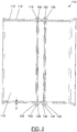
- FIG. 1 a compression sleeve according to the invention is designated quite generally with 10.
- the compression sleeve 10 comprises a cylindrical base body 12, which has a wall 14 with a uniform thickness d.
- the base body 12 or its wall 14 surrounds an interior 16.
- the compression sleeve 10 has in the in Figure 1 illustrated embodiment, two projections 18 and 20, which extend from the outer circumference of the base body 12 with respect to a cylinder axis A of the base body 12 radially outward.
- the two projections 18 and 20 are designed here as projections 18 and 20 running in a ring around the outer circumference of the base body 12.
- the two projections 18 and 20 are formed in one piece with the base body 12 in such a way that the projections 18 and 12 are formed by folding the material of the wall 14 of the base body 12 radially outward.
- the projections 18 and 20 have wave crests 22 and 24, to which flanks 26 and 28 or 30 and 32 respectively adjoin the cylindrical base body 12.
- the base body 12 has a radially outwardly protruding edge 40, which is designed here at a right angle with respect to the base body 12 and as a closed around the outer circumference of the base body 12.
- the edge 40 serves to connect the compression sleeve 10 to a holding element 300 '(see FIG. Figure 6 ) for connecting the compression sleeve 10 to a support sleeve 400 (see Sect. Figure 6 ).
- the base body 12 has a section 44, the diameter of which gradually widens starting from the cylindrical base body 12.
- the section 44 can serve in particular as an insertion aid for a pipe element to be inserted into the compression sleeve 10.
- a stamping point 46 can be seen, which serves to further secure the tubular element between the compression sleeve 10 and the support sleeve 400, in particular in the unpressed state of the press connection.
- the embossing point 46 forms a radially inward protruding projection on its side facing the interior 16. The projection can thus reduce the gap between the compression sleeve 10 and the support sleeve 400 in such a way that there is a clamping effect between the compression sleeve 10 and the tubular element. Inadvertent displacement between the compression sleeve 10 and the tubular element can thus be largely prevented.
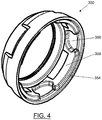
- FIG 2 a second embodiment 110 of a compression sleeve according to the invention is shown, which is essentially identical to the compression sleeve 10, to which reference is hereby expressly made. Elements of the compression sleeve 110 that are identical to the compression sleeve 10 are provided with the same reference numerals as those of the compression sleeve 10, but increased by 100. The compression sleeve 110 will be described below in particular with regard to its differences from the compression sleeve 10.
- the compression sleeve 110 has a cylindrical base body 112 with a wall 114.
- two projections 118 and 120 are formed.
- the projections 118 and 120 are designed as completely radially circumferential rings.
- the projections 118 and 120 each include a crest 122 and 124, two flanks 126 and 128 adjoining the crest 122 and two flanks 130 and 132 adjoining the crest 124.
- the sides of the flanks 126 and 128 or 130 and 132 facing an interior 116 of the base body 112 are not in contact with one another, but a gap 150 or 152 is formed between them, which here in the longitudinal direction of the Base body 112 is measured about 0.05 mm.
- FIG. 3 a third embodiment 210 of a compression sleeve according to the invention is shown, which is essentially identical to the compression sleeve 10 or to the compression sleeve 110, to which reference is hereby expressly made.
- Elements of the compression sleeve 210 that are identical to the compression sleeve 10 or the compression sleeve 110 are provided with the same reference numerals as those of the compression sleeves 10 and 110, but increased by 200 in relation to the compression sleeve 10 and increased by 100 in relation to the compression sleeve 110 Press sleeve 210 will be described below in particular with regard to its differences from press sleeve 10 or from press sleeve 110.
- the compression sleeve 210 has a cylindrical base body 212 with a wall 214.
- two projections 218 and 220 are formed.
- the projections 218 and 220 are designed as completely radially circumferential rings.
- the projections 218 and 220 each include a crest 222 and 224, two flanks 226 and 228 adjoining the crest 222 and two flanks 230 and 232 adjoining the crest 224.
- FIG Figure 3 A gap 250 or 252 resulting from the material folding to form the projections 218 or 220 radially inside the wave crest 222 or 224 is shown in FIG Figure 3 shown merely as a line, which is to be understood according to the present invention in such a way that it is intended to include both a contact between the flanks 226 and 228 or 230 and 232 as well as a spacing of these flanks from one another.
- the longitudinal end 238 of the compression sleeve 210 shown on the left has a toothed structure 254 which comprises projections 256 and recesses 258.
- the toothed structure 254 can have a toothed structure 354, which comprises recesses 356 and projections 358 that match the toothed structure 254, one in FIG Figure 4 shown holding element 300 are brought into engagement.
- the holding element 300 is fastened to the compression sleeve 210 relative to the latter.
- the holding element 300 is designed as an injection-molded part which has been produced in a production step separate from the compression sleeve 210.
- the holding element 300 is accordingly made of a suitable plastic.
- the compression sleeve 210 is shown with the holding element 300 attached to it.
- projections 256 of the compression sleeve 210 engage with recesses 356 of the retaining element 300 and projections 358 of the retaining element 300 engage with recesses 258 of the compression sleeve 210.
- Holding element 300 has a connecting device 360 in the form of a radially inwardly protruding projection 362.
- the compression sleeve 210 or the holding element 300 can be connected to a support sleeve which has a connecting device that matches the connecting device 360 of the holding element 300, in the sense of a snap connection.
- a snap connection is also in Figure 6 to be seen at the reference symbol 360 '.
- the connecting device 360 shown, the holding element 300 and thus the compression sleeve 210 can be rotatably attached to the support sleeve.
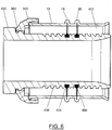
- a press connection according to the invention is shown in an unpressed state, which comprises the press sleeve 10, a support sleeve 400 and a holding element 300 'which is essentially identical to the holding element 300, with the exception of the connection of the holding element 300' to the pressing sleeve 10, which is shown here is formed using the edge 40 of the compression sleeve 10.
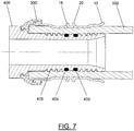
- a pipe element 500 (see FIG. Figure 7 ), which can be attached to the support sleeve 400 by deformation.
- the support sleeve 400 has a seal in the form of two O-rings 404 and 406.
- the two O-rings 404 and 406 are arranged on the support sleeve 400 in such a way that, with the support sleeve 400 over the holding element 300 ' connected compression sleeve 10, below, ie in a radial direction within the two projections 18 and 20 lie.
- the support sleeve 400 also has a structure 408 which engages with the pipe element upon deformation of the compression sleeve 10 and thus the pipe element to be connected, so that pulling the pipe element off the support sleeve 400 can be made more difficult or prevented.
- a tubular element 500 inserted between the support sleeve 400 and the compression sleeve 10 is deformed in such a way that it extends into the structure 408, i.e. forms a form fit with the structure 408. Furthermore, in the pressed state, the tubular element 500 presses on the two O-rings 404 and 406 in such a way that their originally circular cross-section has deformed into an elliptical cross-section. This creates a fluid-tight connection between the pipe element 500 and the support sleeve 400, so that fluid flowing through the pipe element 500 cannot escape between the support sleeve 400 and the pipe element 500.
- the area of the two projections 18 and 20 of the compression sleeve 10 lies above the area of the seal, i.e. the two O-rings 404 and 406.
- a pressing tool acts on the press sleeve 10 and thus on the tubular element 500 in such a way that the tubular element 500 is pressed reliably and fluid-tight onto the two O-rings 404 and 406.
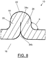
- Figure 8 is an enlarged detail from Figure 1 shown, which shows the projection 18 of the compression sleeve 10.
- the flanks 26 and 28 are folded towards each other in such a way that a first section 34a of the inner surfaces of the flanks 26 and 28 rests against one another and a second section 34b of the inner surfaces of the flanks 26 and 28 gradually extends in the direction of the interior 16 of the base body 12 opens, that is to say that the distance between the mutually facing inner surfaces of the flanks 26 and 28 gradually increases.
- the first section 34a can extend over a length of 300 ⁇ m to 600 ⁇ m, preferably over a length of 325 ⁇ m to 525 ⁇ m.
- the second section 34 b can in particular extend over a length of 400 ⁇ m to 700 ⁇ m, preferably over a length of 475 ⁇ m to 675 ⁇ m.
Description
Die vorliegende Erfindung betrifft eine Presshülse zur Verbindung von Kunststoffrohren gemäß dem Oberbegriff des Anspruchs 1.The present invention relates to a compression sleeve for connecting plastic pipes according to the preamble of claim 1.
Um Rohrelemente miteinander zu verbinden, werden Pressverbindungen verwendet. Dabei werden zwei Rohrelemente auf eine Stützhülse aufgeschoben und anschließend derart deformiert, dass zwischen Rohrelement und Stützhülse ein Formschluss oder zumindest ein hoher Reibschluss entsteht, welcher ausreichend stark ist, um eine Trennung der beiden über die Stützhülse verbundenen Rohrelemente zu verhindern. Zur gezielten Deformation der Rohrelemente wird eine das jeweilige Rohrelement abschnittsweise umgebende Presshülse verwendet.Press connections are used to connect pipe elements to one another. Two pipe elements are pushed onto a support sleeve and then deformed in such a way that a form fit or at least a high frictional connection is created between pipe element and support sleeve, which is sufficiently strong to prevent separation of the two pipe elements connected via the support sleeve. For the targeted deformation of the tube elements, a compression sleeve surrounding the respective tube element in sections is used.
Aus der
Aus dem Dokument
Insbesondere in Bezug auf die Fertigungskosten der Komponenten derartiger Pressverbindungen besteht ständiges Verbesserungspotenzial.In particular with regard to the production costs of the components of such press connections, there is constant potential for improvement.
Es ist daher die Aufgabe der vorliegenden Erfindung eine Presshülse bzw. eine Pressverbindung bereitzustellen, welche mit vereinfachten Mitteln und insbesondere im Vergleich zum Stand der Technik kosteneffizienter hergestellt werden kann.It is therefore the object of the present invention to provide a compression sleeve or a compression connection which can be produced with simplified means and in particular more cost-effectively compared to the prior art.
Diese Aufgabe wird gelöst durch eine Presshülse zur Verbindung von Kunststoffrohren gemäß Anspruch 1.This object is achieved by a compression sleeve for connecting plastic pipes according to claim 1.
Bei aus dem Stand der Technik bekannten Presshülsen wurde der wenigstens eine Vorsprung üblicherweise unter Verwendung eines Tiefziehverfahrens ausgebildet, wodurch es im Bereich des wenigstens einen Vorsprungs zu einer Materialdehnung und somit zu einer Schwächung der Wandungsstärke kommt. Damit auch nach erfolgter Ausbildung des wenigstens einen Vorsprungs, d.h. nach der Schwächung der Wandungsstärke im Bereich des wenigstens einen Vorsprungs, eine für die vorgesehene Verwendung der Presshülse ausreichende Wandungsstärke im Bereich des wenigstens einen Vorsprungs vorlag, mussten Grundkörper mit entsprechend hohen Wandungsstärken verwendet werden oder der Grundkörper musste mit Zusatzelementen zur selektiven Stabilisierung der Wandung des Grundkörpers versehen werden. Auf Grund der Tatsache, dass der wenigstens eine Vorsprung der erfindungsgemäßen Presshülse durch eine Materialfaltung der Wandung des Grundkörpers ausgebildet ist, wird die Wandungsstärke des Grundkörpers im Bereich des Vorsprungs nicht geschwächt. Es können zur Herstellung der erfindungsgemäßen Presshülse daher Grundkörper verwendet werden, welche eine geringere Wandungsstärke aufweisen als Grundkörper bekannter Presshülsen, ohne dass es einer Anordnung zusätzlicher Stützelemente bedarf.In compression sleeves known from the prior art, the at least one projection was usually formed using a deep-drawing process, which results in material expansion in the area of the at least one projection and thus a weakening of the wall thickness. So that even after the at least one projection has been formed, ie after the wall thickness has been weakened in the area of the at least one projection, there is sufficient wall thickness in the area of the at least one projection for the intended use of the compression sleeve, base bodies with correspondingly high wall thicknesses had to be used or the The base body had to be provided with additional elements for the selective stabilization of the wall of the base body. Due to the fact that the at least one projection of the compression sleeve according to the invention is formed by a material fold in the wall of the base body, the wall thickness of the base body is not weakened in the area of the projection. For the production of the compression sleeve according to the invention, base bodies can therefore be used which have a smaller wall thickness than the base body of known compression sleeves, without the need for an arrangement of additional support elements.
Der wenigstens eine Vorsprung der Presshülse kann insbesondere ermöglichen, dass unter Verwendung eines entsprechenden Presswerkzeugs zunächst nur ein Abschnitt des Grundkörpers der Presshülse deformiert wird und gemäß dem vorbestimmten Zusammenwirken der Pressbacke mit der Presshülse nachfolgend der Bereich des wenigstens einen Vorsprungs deformiert wird. Ferner kann der wenigstens eine Vorsprung der Ausrichtung eines Presswerkzeugs relativ zu der Presshülse dienen.The at least one projection of the compression sleeve can in particular make it possible, using a corresponding Pressing tool initially only a portion of the base body of the press sleeve is deformed and according to the predetermined interaction of the press jaw with the press sleeve, the area of the at least one projection is subsequently deformed. Furthermore, the at least one projection can serve to align a pressing tool relative to the pressing sleeve.
Die Verwendung von Grundkörpern mit einer, im Vergleich zum Stand der Technik, dünneren Wandungsstärke kann auch zur Folge haben, dass ein Presswerkzeug bzw. eine gesamte Pressvorrichtung zur Verformung der Presshülse einfacher, insbesondere in Bezug auf die auf die Presshülse zu übertragenden Kräfte, ausgebildet ist.The use of base bodies with a wall thickness that is thinner compared to the prior art can also result in a pressing tool or an entire pressing device for deforming the compression sleeve being designed more simply, in particular with regard to the forces to be transmitted to the compression sleeve .
Zusätzlich zu der Möglichkeit, Grundkörper mit einer dünneren Wandungsstärke zu verwenden, kann die "Aufeinanderzufaltung" der beiden Flanken des Vorsprungs dem Vorsprung eine hohe Stabilität verleihen, so dass dieser zuverlässig die Funktion der Ausrichthilfe für das Presswerkzeug oder/und der Übertragung von Kräften auf das Rohrelement erfüllen kann. Wie bereits voranstehend erwähnt, kann die vorliegende Erfindung den Vorteil bieten, dass kein zusätzliches den Vorsprung stützendes Element mit der Presshülse verbunden werden muss. Dies kann sich weiter vorteilhaft auf die Fertigungskosten der erfindungsgemäßen Presshülse auswirken.In addition to the possibility of using the base body with a thinner wall thickness, the "unfolding" of the two flanks of the projection can give the projection a high degree of stability, so that it reliably functions as an alignment aid for the pressing tool and / or the transfer of forces to the Can meet tubular element. As already mentioned above, the present invention can offer the advantage that no additional element supporting the projection has to be connected to the compression sleeve. This can also have an advantageous effect on the production costs of the compression sleeve according to the invention.
Es sei an dieser Stelle erwähnt, dass der Übergang der dem Wellenberg entgegengesetzten Enden der Flanken des Vorsprungs in den zylindrischen Grundkörper an der dem Innenraum der Presshülse zugewandten Seite der Wandung des Grundkörpers einen Radius aufweisen kann, welcher bei der Betrachtung des Abstands der beiden Flanken zueinander unbeachtet bleiben kann. Alternativ kann der Vorsprung in dem Grundkörper auch derart ausgebildet sein, dass ein derartiger Radius nicht, oder beispielsweise mit einem Wert von unter 0,5 mm, insbesondere von unter 0,25 mm, ausgebildet ist. Hierfür kann die Verwendung eines Kerns vorteilhaft sein, auf welchen der Grundkörper vor der Ausbildung des wenigstens einen Vorsprungs aufgeschoben wird, wobei der Außendurchmesser des Kerns vorteilhafterweise im Wesentlichen dem Innendurchmesser des Grundkörpers entsprechen kann, so dass gewährleistet werden kann, dass sich der Grundkörper lediglich nach radial außen verformt. Der Kern kann dabei z.B. verlagerbare Vorsprünge aufweisen, welche eine Auswölbung der Wandung des Grundkörpers an einer vorbestimmten Stelle unterstützen können. Alternativ oder zusätzlich kann der Grundkörper in einer den Grundkörper zumindest teilweise umgebenden Hülle angeordnet werden, deren Innendurchmesser im Wesentlichen dem Außendurchmesser des Grundkörpers entspricht. Die Hülle kann Ausnehmungen aufweisen, welche dazu eingerichtet sind, den Abschnitt der Wandung des Grundkörpers, welcher den wenigstens einen Vorsprung des Grundkörpers ausbildet, nach dessen Umformung, aufzunehmen. Die Hülle kann dabei auch aus mehreren Elementen ausgebildet sein, welche beispielsweise zueinander verlagerbar sind.It should be mentioned at this point that the transition of the ends of the flanks of the projection opposite the wave crest into the cylindrical base body on the side of the wall of the base body facing the interior of the compression sleeve can have a radius which when considering the distance between the two flanks can go unnoticed. Alternatively, the projection in the base body can also be designed in such a way that such a radius is not formed, or is, for example, formed with a value of less than 0.5 mm, in particular less than 0.25 mm. For this purpose, the use of a core can be advantageous, on which the base body is pushed on before the formation of the at least one projection, the outer diameter of the core advantageously being able to correspond essentially to the inner diameter of the base body, so that it can be ensured that the base body is only deformed radially outward. The core can have, for example, displaceable projections which can support a bulging of the wall of the base body at a predetermined point. As an alternative or in addition, the base body can be arranged in a shell which at least partially surrounds the base body, the inside diameter of which essentially corresponds to the outside diameter of the base body. The shell can have recesses which are designed to receive the section of the wall of the base body which forms the at least one projection of the base body after it has been deformed. The shell can also be formed from a plurality of elements which, for example, can be displaced relative to one another.
Der Grundkörper kann aus einem Metall, insbesondere aus Aluminium, Messing, Stahl oder Edelstahl, ausgebildet sein.The base body can be formed from a metal, in particular from aluminum, brass, steel or stainless steel.
Derartige Presshülsen bzw. Pressverbindungen sind insbesondere für Rohrdurchmesser im Bereich von 16 - 32 mm geeignet. Entsprechend kann der Innendurchmesser einer erfindungsgemäßen Presshülse im Bereich von 16 - 32 mm liegen.Such compression sleeves or compression connections are particularly suitable for pipe diameters in the range of 16-32 mm. Correspondingly, the inside diameter of a compression sleeve according to the invention can be in the range of 16-32 mm.
Ein Bereich, in welchem sich ein Vorsprung in Längserstreckungsrichtung der Presshülse gemessen erstreckt, kann von 1,1 mm bis 1,5 mm, insbesondere von 1,2 mm bis 1,4 mm, vorteilhafterweise 1,3 mm, betragen.A region in which a projection extends, measured in the direction of longitudinal extension of the compression sleeve, can be from 1.1 mm to 1.5 mm, in particular from 1.2 mm to 1.4 mm, advantageously 1.3 mm.
Eine Höhe eines Vorsprungs, gemessen von dem Innenumfang des zylindrischen Grundkörpers der Presshülse nach radial außen, kann von 1,5 mm bis 1,8 mm, insbesondere von 1,55 mm bis 1,7 mm, vorteilhafterweise 1,6 mm betragen.A height of a projection, measured radially outward from the inner circumference of the cylindrical base body of the compression sleeve, can be from 1.5 mm to 1.8 mm, in particular from 1.55 mm to 1.7 mm, advantageously be 1.6 mm.
Ein so ausgebildeter Vorsprung kann eine hervorragende Stabilität und eine gute Durchführbarkeit der Materialfaltung vereinen.A projection formed in this way can combine excellent stability and good feasibility of folding the material.
Vorteilhafterweise kann die Presshülse wenigstens zwei Vorsprünge umfassen, welche in einer Längserstreckungsrichtung des Grundkörpers zueinander beabstandet sind.The compression sleeve can advantageously comprise at least two projections which are spaced apart from one another in a direction of longitudinal extent of the base body.
Die wenigstens zwei Vorsprünge sind derart ausgebildet, dass die erfindungsgemäße Presshülse mit unterschiedlichsten Presswerkzeugen in Eingriff bringbar sein kann. So kann ein Presswerkzeug beispielsweise mit einem zwischen den beiden Vorsprüngen ausgebildeten Bereich eingreifen und selektiv auf diesen Bereich einwirken. Ebenso ist es denkbar, dass ein Presswerkzeug mit den wenigstens zwei Vorsprüngen im Sinne eines sehr breiten Vorsprungs eingreifen kann, d.h. jeweils mit der Außenseite der Flanke eines Vorsprungs, welche nicht zu dem anderen Vorsprung weist, mit welchem der eine Vorsprung im Sinne des einen breiten Vorsprungs zusammenwirkt.The at least two projections are designed such that the compression sleeve according to the invention can be brought into engagement with a wide variety of compression tools. For example, a pressing tool can engage with an area formed between the two projections and act selectively on this area. It is also conceivable that a pressing tool can engage with the at least two projections in the sense of a very wide projection, ie in each case with the outside of the flank of a projection which does not face the other projection with which one projection in the sense of the one wide Collaboration in advance.
Wie eingangs bereits erwähnt, ist es natürlich im Rahmen dieser Erfindung ebenfalls denkbar, dass das Presswerkzeug frei positioniert werden kann, wobei der wenigstens eine Vorsprung ein sequenzielles Deformieren der Presshülse ermöglichen kann.As already mentioned at the beginning, it is of course also conceivable within the scope of this invention that the pressing tool can be positioned freely, wherein the at least one projection can enable the pressing sleeve to be deformed sequentially.
Der Abstand zwischen zwei Vorsprüngen kann von 3 mm bis 5 mm, insbesondere von 3,5 mm bis 4,5 mm, vorteilhafterweise 4,0 mm, betragen. Ein Abstand zwischen zwei Vorsprüngen in diesem Bereich kann sich besonders vorteilhaft auf die Verpresseigenschaften der Stützhülse, und damit der gesamten Pressverbindung, auswirken.The distance between two projections can be from 3 mm to 5 mm, in particular from 3.5 mm to 4.5 mm, advantageously 4.0 mm. A distance between two projections in this area can have a particularly advantageous effect on the pressing properties of the support sleeve, and thus of the entire press connection.
In einer Weiterbildung der Erfindung kann wenigstens ein Vorsprung vollständig um den Außenumfang des Grundkörpers herum verlaufend ausgebildet sein.In a further development of the invention, at least one projection be designed to run completely around the outer circumference of the base body.
Es ist somit möglich, dass das Presswerkzeug relativ zu der Presshülse zuverlässig in einer vorbestimmten Weise ausgerichtet werden kann, ohne dass eine rotatorische Ausrichtung der Presshülse relativ zu dem Presswerkzeug beachtet werden muss.It is thus possible for the press tool to be reliably aligned in a predetermined manner relative to the press sleeve without having to consider a rotational alignment of the press sleeve relative to the press tool.
Besonders vorteilhaft kann es dabei sein, den um den Außenumfang des Grundkörpers herum verlaufenden Vorsprung parallel zu wenigstens einem der Längsenden des Grundkörpers auszubilden.It can be particularly advantageous here to form the projection running around the outer circumference of the base body parallel to at least one of the longitudinal ends of the base body.
In dem Fall, dass wenigstens zwei Vorsprünge als vollständig um den Außenumfang des Grundkörpers herum verlaufende Ringe ausgebildet sind, kann es ferner vorteilhaft sein, diese parallel zueinander ausgerichtet auszubilden, um beispielsweise eine gleichbleibende Ausbildung des zwischen den beiden Vorsprüngen gebildeten Bereichs um den Außenumfang des Grundkörpers herum gewährleisten zu können.In the event that at least two projections are designed as rings running completely around the outer circumference of the base body, it can also be advantageous to make them aligned parallel to one another, for example to ensure that the area formed between the two projections around the outer circumference of the base body remains the same around to be able to guarantee.
Im Rahmen der vorliegenden Erfindung ist es natürlich denkbar, dass der Vorsprung nicht zwangsläufig als geschlossener um den Außenumfang des Grundkörpers herum verlaufender Ring, sondern als zumindest in einem Abschnitt unterbrochener Ring ausgebildet ist.In the context of the present invention it is of course conceivable that the projection is not necessarily designed as a closed ring running around the outer circumference of the base body, but rather as a ring that is interrupted in at least one section.
Vorteilhafterweise kann die Wandungsstärke des Grundkörpers einen Wert von 0,5 mm bis 1,0 mm, insbesondere von 0,6 mm bis 0,8 mm, aufweisen.The wall thickness of the base body can advantageously have a value from 0.5 mm to 1.0 mm, in particular from 0.6 mm to 0.8 mm.
Grundkörper mit derartigen Wandungsstärken können eine gute Deformierbarkeit, insbesondere in Bezug auf die Materialfaltung zur Ausbildung des wenigstens einen Vorsprungs, mit einer hohen Stabilität vereinen, so dass eine zuverlässige Pressverbindung mit dem zu verbindenden Rohrelement gewährleistet werden kann.Base bodies with such wall thicknesses can combine good deformability, in particular with regard to the material folding for forming the at least one projection, with high stability, so that a reliable press connection with the pipe element to be connected can be ensured.
Insbesondere kann der wenigstens eine Vorsprung durch Stauchung des Grundköpers in dessen Längserstreckungsrichtung ausgebildet sein.In particular, the at least one projection can be formed by upsetting the base body in the direction of its longitudinal extension.
Der Grundkörper kann dabei mit auf die beiden Längsenden, beispielsweise flächig auf die beiden Stirnseiten der Längsenden des Grundkörpers, einwirkenden Kräften beaufschlagt werden, welche groß genug sind, damit sich die Wandung des Grundkörpers aus der Mantelfläche des zylindrischen Grundkörpers hervor wölbt und so die Materialfaltung in der Wandung des Grundkörpers erzeugt wird. Hierfür kann die oben erwähnte Verwendung eines Kerns oder/und einer Hülle besonders vorteilhaft sein.The base body can be acted upon with forces acting on the two longitudinal ends, for example flat on the two end faces of the longitudinal ends of the base body, which are large enough for the wall of the base body to bulge out of the outer surface of the cylindrical base body and thus the material fold in the wall of the base body is generated. The above-mentioned use of a core and / or a shell can be particularly advantageous for this.
Vorteilhafterweise können sich Außenflächen der Flanken wenigstens eines Vorsprungs im Wesentlichen orthogonal zu dem zylindrischen Grundkörper der Presshülse erstrecken. Es sei erwähnt, dass der Begriff "Außenflächen" zweidimensionale Abschnitte der Außenflächen der Flanken beschreiben soll. Somit ist deutlich, dass ein sich in einem Punkt oder einer Linie erstreckender Übergang einer ersten Krümmung in eine zweite Krümmung, beispielsweise des Radius zwischen Grundkörper und Flanke in den Wellenberg, nicht als zum Grundkörper orthogonale Außenfläche der Flanke angesehen werden kann. Durch die orthogonale Ausrichtung der Außenseiten der Flanken eines Vorsprungs kann die Stabilität des Vorsprungs gegenüber einer auf den Vorsprung nach radial innen einwirkenden Kraft erhöht werden.Advantageously, outer surfaces of the flanks of at least one projection can extend essentially orthogonally to the cylindrical base body of the compression sleeve. It should be mentioned that the term “outer surfaces” is intended to describe two-dimensional sections of the outer surfaces of the flanks. It is thus clear that a transition from a first curvature to a second curvature extending at one point or in a line, for example the radius between the base body and flank in the wave crest, cannot be viewed as an outer surface of the flank orthogonal to the base body. As a result of the orthogonal alignment of the outer sides of the flanks of a projection, the stability of the projection with respect to a force acting radially inward on the projection can be increased.
Die zueinander weisenden Innenflächen der Flanken liegen in einem ersten dem Wellenberg benachbarten Abschnitt aneinander an und weisen in einem zweiten dem Innenraum des Grundkörpers benachbarten Abschnitt einen in Richtung des Innenraums des Grundkörpers ansteigenden Abstand auf. Durch das Ausbilden des ersten Abschnitts kann die Stabilität des Vorsprungs gegenüber einer auf den Vorsprung nach radial innen einwirkenden Kraft als auch gegenüber einer auf den Vorsprung in einer zu der Mittelachse des Grundkörpers parallel wirkenden Kraft erhöht werden. Die Ausbildung des zweiten Abschnitts wiederum kann eine Kerbwirkung an dem Übergang zwischen einer Flanke des Vorsprungs und dem Grundkörper vermindern, da der Übergang über einen größeren Abschnitt der Wandung der Presshülse stattfinden kann.The mutually facing inner surfaces of the flanks abut one another in a first section adjacent to the wave crest and have a spacing that increases in the direction of the interior of the base body in a second section adjacent to the interior of the base body. By forming the first section, the stability of the projection in relation to a force acting radially inward on the projection and in relation to a force acting on the projection can be increased in one the central axis of the base body acting parallel to the force can be increased. The formation of the second section can in turn reduce a notch effect at the transition between a flank of the projection and the base body, since the transition can take place over a larger section of the wall of the compression sleeve.
In einer Weiterbildung der vorliegenden Erfindung kann die Presshülse ein Halteelement umfassen, vermittels welchem die Presshülse mit einem nicht zu der Presshülse gehörenden Bauteil verbunden werden kann.In a further development of the present invention, the compression sleeve can comprise a holding element by means of which the compression sleeve can be connected to a component that does not belong to the compression sleeve.
Die Presshülse kann durch das Halteelement, welches auch "Fixierring" genannt wird, beispielsweise mit einer Stützhülse verbunden werden. Die Stützhülse kann sich dabei in den Innenraum der Presshülse hinein erstrecken. Vorteilhafterweise kann die Presshülse über das Halteelement derart mit der Stützhülse verbunden werden, dass die Presshülse und die Stützhülse zueinander konzentrisch angeordnet sind. In einen Spalt zwischen der Presshülse und der Stützhülse kann ein Rohrelement eingeführt werden, welches durch Deformation fest mit der Stützhülse verbunden werden kann.The compression sleeve can be connected, for example, to a support sleeve by the holding element, which is also called a "fixing ring". The support sleeve can extend into the interior of the compression sleeve. The compression sleeve can advantageously be connected to the support sleeve via the holding element in such a way that the compression sleeve and the support sleeve are arranged concentrically to one another. A tubular element can be inserted into a gap between the compression sleeve and the support sleeve, which pipe element can be firmly connected to the support sleeve by deformation.
Das Halteelement kann dabei relativ zu der Stützhülse oder/und zu der Presshülse rotierbar gehaltert sein.The holding element can be held rotatably relative to the support sleeve and / or to the compression sleeve.
Die Stützhülse ist vorteilhafterweise aus Messing oder aus PPSU hergestellt.The support sleeve is advantageously made of brass or of PPSU.
Bezüglich des Zusammenwirkens der Presshülse mit der Stützhülse sei auch auf die Beschreibung der Pressverbindung weiter unten verwiesen.With regard to the interaction of the compression sleeve with the support sleeve, reference is also made to the description of the compression connection below.
Vorteilhafterweise kann das Halteelement als von dem Grundkörper getrenntes und mit dem Grundkörpers verbindbares Element ausgebildet sein.The holding element can advantageously be designed as an element which is separate from the base body and can be connected to the base body.
Somit können das Halteelement und der Grundkörper in getrennten Fertigungsschritten und beispielsweise unter Verwendung unterschiedlicher Fertigungsverfahren hergestellt werden. Da das Halteelement im Wesentlichen der Positionierung der Presshülse relativ zu der Stützhülse dient, kann das Halteelement aus einem Kunststoff, insbesondere aus Polypropylen (PP) oder aus HDPE, ausgebildet sein.Thus, the holding element and the base body can be manufactured in separate manufacturing steps and, for example, using different manufacturing processes. Since the holding element essentially serves to position the compression sleeve relative to the support sleeve, the holding element can be made from a plastic, in particular from polypropylene (PP) or from HDPE.
Vorteilhafterweise kann das Halteelement als Spritzgußteil ausgebildet sein.The holding element can advantageously be designed as an injection-molded part.
Da die Vorteile von Spritzgussverfahren insbesondere bei hohen Stückzahlen zum Tragen kommen, kann es vorteilhaft sein, dass eine Verbindungsvorrichtung der Presshülse zur Verbindung mit dem Halteelement oder/und eine Verbindungsvorrichtung der Stützhülse zur Verbindung mit dem Halteelement über eine Baureihe von Presshülsen oder/und Stützhülsen, welche wenigstens in einem Aspekt voneinander verschiedene Geometrien aufweisen, identisch ausgebildet ist/sind. Somit können für die gesamte Baureihe der Presshülsen bzw. Stützhülsen identische Halteelemente verwendet werden.Since the advantages of injection molding processes come into play in particular with large quantities, it can be advantageous that a connection device of the compression sleeve for connection to the holding element and / or a connection device of the support sleeve for connection to the holding element via a series of compression sleeves and / or support sleeves, which have geometries which differ from one another in at least one aspect, is / are embodied identically. This means that identical holding elements can be used for the entire series of compression sleeves or support sleeves.
Es sei erwähnt, dass es natürlich im Rahmen der vorliegenden Erfindung ebenfalls denkbar ist, dass das Halteelement direkt an die Presshülse oder Stützhülse angespritzt wird.It should be mentioned that it is of course also conceivable within the scope of the present invention that the holding element is molded directly onto the compression sleeve or support sleeve.
In einer Weiterbildung der vorliegenden Erfindung kann das Halteelement eine Verzahnungsstruktur mit Vorsprüngen und Ausnehmungen aufweisen, welche dazu eingerichtet ist, mit einer Verzahnungsstruktur der Presshülse in Eingriff bringbar zu sein, welche entsprechende Ausnehmungen und Vorsprünge aufweisen kann.In a further development of the present invention, the holding element can have a toothed structure with projections and recesses, which is designed to be able to be brought into engagement with a toothed structure of the compression sleeve, which can have corresponding recesses and projections.
Durch die zueinander passenden und miteinander in Eingriff stehenden Verzahnungsstrukturen des Halteelements und der Presshülse wird das Halteelement relativ zu der Presshülse sowohl axial als auch rotatorisch gesichert.Due to the mutually matching and mutually engaging toothed structures of the holding element and the compression sleeve, the holding element is both axial and rotational relative to the compression sleeve secured.
Die Verzahnungsstruktur der Presshülse kann dabei den Vorteil aufweisen, dass diese gestanzt werden kann, wohingegen ein Rand zur Aufnahme des Halteelements üblicherweise umgeformt wird.The toothed structure of the compression sleeve can have the advantage that it can be punched, whereas an edge for receiving the holding element is usually reshaped.
In einem zweiten Aspekt betrifft die vorliegende Erfindung eine Pressverbindung, umfassend eine erfindungsgemäße Presshülse gemäß obiger Beschreibung und eine Stützhülse, welche dazu eingerichtet ist, mit einem Rohr verbunden zu werden, wobei die Presshülse mit der Stutzhülse in einer vorbestimmten Position in Eingriff bringbar ist.In a second aspect, the present invention relates to a compression connection, comprising a compression sleeve according to the invention as described above and a support sleeve which is designed to be connected to a pipe, the compression sleeve being engageable with the support sleeve in a predetermined position.
In Bezug auf die Presshülse oder/und die Stützhülse sei an dieser Stelle auch ausdrücklich auf die obige Beschreibung des entsprechenden Elements verwiesen.With regard to the compression sleeve and / or the support sleeve, reference is also expressly made at this point to the above description of the corresponding element.
Es ist selbstverständlich, dass die erfindungsgemäße Pressverbindung, welche in Bezug auf eine einzelne Pressverbindung mit einem Rohr beschrieben werden wird, im Rahmen der Kopplung von zwei Rohrelementen zu sehen ist. Dabei kann die Stützhülse im Wesentlichen symmetrisch ausgebildet sein, so dass an der Stützhülse zwei erfindungsgemäße Presshülsen angeordnet werden können, wobei wiederum jeweils zwischen Presshülse und Stützhülse eines der zu koppelnden Rohre angeordnet werden kann. Durch Deformation der beiden Rohrelemente können diese relativ zu der Stützhülse, und somit relativ zueinander, fixiert werden.It goes without saying that the press connection according to the invention, which will be described with reference to a single press connection with a pipe, is to be seen in the context of the coupling of two pipe elements. The support sleeve can be designed essentially symmetrically so that two compression sleeves according to the invention can be arranged on the support sleeve, with one of the pipes to be coupled again being able to be arranged between the compression sleeve and the support sleeve. By deforming the two tubular elements, they can be fixed relative to the support sleeve, and thus relative to one another.
Im unverpressten Zustand kann zwischen der Stützhülse und dem Rohrelement eine Leckage stattfinden, d.h. es kann Fluid zwischen Stützhülse und Rohr, und somit aus dem Rohr, austreten. Die Pressverbindung erfüllt dabei auch die Funktion, eine fluiddichte Verbindung zwischen Stützhülse und Rohrelement auszubilden.In the unpressed state, a leak can take place between the support sleeve and the pipe element, ie fluid can escape between the support sleeve and the pipe, and thus out of the pipe. The press connection also fulfills the function of forming a fluid-tight connection between the support sleeve and the tubular element.
Vorteilhafterweise kann dabei der Eingriff der Presshülse oder eines mit der Presshülse verbundenen Halteelements mit der Stutzhülse eine Schnappverbindung umfassen.Advantageously, the engagement of the compression sleeve or a holding element connected to the compression sleeve with the support sleeve can comprise a snap connection.
Die Schnappverbindung kann dabei insbesondere an dem Abschnitt des Halteelements, welcher zur Verbindung mit der Stützhülse ausgebildet ist, oder/und an dem Abschnitt des Halteelements, welcher zur Verbindung mit der Presshülse ausgebildet ist, vorgesehen sein.The snap connection can in particular be provided on the section of the holding element which is designed to be connected to the support sleeve and / or to the section of the holding element which is designed to be connected to the compression sleeve.
In einer Weiterbildung der Erfindung kann die Pressverbindung eine an der Stützhülse angebrachte Dichtung umfassen, welche insbesondere als O-Ring ausgebildet ist, und welche dazu eingerichtet ist, einen Spalt zwischen der Stützhülse und dem damit verbundenen Rohr abzudichten, wobei, in einer radialen Richtung der Stützhülse gesehen, der Bereich des wenigstens einen Vorsprungs des Grundkörpers und die Dichtung der Stützhülse aufeinanderfolgend sind.In a further development of the invention, the press connection can comprise a seal attached to the support sleeve, which is designed in particular as an O-ring, and which is designed to seal a gap between the support sleeve and the pipe connected to it, wherein, in a radial direction, the Seen support sleeve, the region of the at least one projection of the base body and the seal of the support sleeve are consecutive.
Auf eine Deformation der Presshülse durch das Presswerkzeug hin kann die Presshülse auf das zu verbindende Rohr und dieses auf die an der Stützhülse angebrachte Dichtung gedrückt werden. Somit kann eine fluiddichte Verbindung zwischen der Stützhülse und dem Rohr hergestellt werden. Vorteilhafterweise kann die Dichtung wenigstens zwei O-Ringe umfassen. Der wenigstens eine Vorsprung des Grundkörpers kann dabei in Längserstreckungsrichtung der Stützhülse relativ zu dieser derart angeordnet sein, dass er über einem Bereich liegt, welcher sich über oder zwischen den beiden O-Ringen erstreckt.If the compression sleeve is deformed by the compression tool, the compression sleeve can be pressed onto the pipe to be connected and the latter onto the seal attached to the support sleeve. A fluid-tight connection can thus be established between the support sleeve and the pipe. The seal can advantageously comprise at least two O-rings. The at least one projection of the base body can be arranged in the longitudinal direction of the support sleeve relative to the latter in such a way that it lies over an area which extends over or between the two O-rings.
Vorzugsweise kann die Pressverbindung ferner eine an der Stützhülse vorgesehene Struktur umfassen, innerhalb welcher sich die radiale Ausdehnung der Stützhülse ändert, umfassend beispielsweise mindestens eine Rippe oder mindestens eine Nut, wobei, in einer radialen Richtung der Stützhülse gesehen, der Bereich des wenigstens einen Vorsprungs des Grundkörpers und die Struktur der Stützhülse aufeinanderfolgend sind.Preferably, the press connection can further comprise a structure provided on the support sleeve, within which the radial extension of the support sleeve changes, comprising, for example, at least one rib or at least one groove, wherein, in a radial direction, the Seen support sleeve, the region of the at least one projection of the base body and the structure of the support sleeve are consecutive.
Insbesondere kann die sich ändernde Struktur ein in Längserstreckungsrichtung der Stützhülse fortlaufendes Sägezahnprofil aufweisen, welches derart ausgebildet ist, dass es ein Aufstecken des Rohrs auf die Stützhülse erleichtert und ein Abziehen des Rohrs von der Stützhülse erschwert. Dieses Zusammenwirken kann bereits vor der Deformation der Presshülse auftreten und auf eine Deformation der Presshülse hin verstärkt werden. Die Stützhülse kann die sich ändernde Struktur über die gesamte Länge, welche für ein Aufstecken des Rohrs zur Verfügung steht, aufweisen, beispielsweise in einem Bereich von einer Verbindungseinrichtung der Stützhülse mit dem Halteelement oder der Presshülse selbst bis zu einem entsprechenden Längsende der Stützhülse.In particular, the changing structure can have a sawtooth profile which continues in the longitudinal direction of the support sleeve and is designed in such a way that it makes it easier to plug the pipe onto the support sleeve and makes it more difficult to pull the pipe off the support sleeve. This interaction can occur even before the compression sleeve is deformed and can be intensified in response to a deformation of the compression sleeve. The support sleeve can have the changing structure over the entire length that is available for attaching the pipe, for example in a region from a connecting device of the support sleeve to the holding element or the compression sleeve itself to a corresponding longitudinal end of the support sleeve.
Ein Sägezahnprofil kann insbesondere bei einer Ausbildung der Stützhülse aus Messing vorteilhaft sein. Bei einer Ausbildung der Stützhülse aus Kunststoff, beispielsweise PPSU, kann das Sägezahnprofil abgerundet sein, um eine entsprechende Kerbwirkung zu reduzieren oder vollständig zu vermeiden.A sawtooth profile can be advantageous in particular when the support sleeve is made of brass. If the support sleeve is made of plastic, for example PPSU, the sawtooth profile can be rounded in order to reduce or completely avoid a corresponding notch effect.
In einer Weiterbildung der Erfindung kann ein maximaler Außendurchmesser der Dichtung geringer sein als ein maximaler Außendurchmesser der beispielsweise als Sägezahnprofil ausgebildeten Struktur. Dies kann zur Folge haben, dass auf eine Deformation des Rohrelements hin dieses zuerst mit der Struktur und nachfolgend mit der Dichtung in Eingriff tritt. Auf diese Weise kann eine besonders stabile Verbindung des Rohrelements mit der Stützhülse und dennoch eine gute Abdichtung des Spalts zwischen Rohrelement und Stützhülse erreicht werden.In a further development of the invention, a maximum outer diameter of the seal can be smaller than a maximum outer diameter of the structure, for example designed as a sawtooth profile. This can have the consequence that if the tubular element is deformed, it first engages with the structure and then with the seal. In this way, a particularly stable connection between the pipe element and the support sleeve and, nevertheless, good sealing of the gap between the pipe element and the support sleeve can be achieved.
Zur weiteren Sicherung des Rohrelements zwischen der Presshülse und der Stützhülse insbesondere im unverpressten Zustand der Pressverbindung, kann die Presshülse einen Prägepunkt aufweisen, welcher einen nach radial innen vorstehenden Vorsprung ausbildet. Der Vorsprung kann somit das Spaltmaß zwischen Presshülse und Stützhülse derart verringern, dass es zu einer Klemmwirkung zwischen der Presshülse und dem Rohrelement kommt.To further secure the tubular element between the compression sleeve and the support sleeve, especially when the compression connection is not pressed, the compression sleeve can have an embossing point which forms a radially inwardly protruding projection. The projection can thus reduce the gap between the compression sleeve and the support sleeve in such a way that there is a clamping effect between the compression sleeve and the tubular element.
Die vorliegende Erfindung wird im Folgenden anhand der begleitenden Zeichnungen näher erläutert werden.The present invention will be explained in more detail below with reference to the accompanying drawings.
- Figur 1Figure 1
- eine Seitenquerschnittsansicht einer ersten Ausführungsform einer erfindungsgemäßen Presshülse;a side cross-sectional view of a first embodiment of a compression sleeve according to the invention;
- Figur 2Figure 2
- eine Seitenquerschnittsansicht einer zweiten Ausführungsform einer erfindungsgemäßen Presshülse;a side cross-sectional view of a second embodiment of a compression sleeve according to the invention;
- Figur 3Figure 3
- eine Seitenquerschnittsansicht einer dritten Ausführungsform einer erfindungsgemäßen Presshülse;a side cross-sectional view of a third embodiment of a compression sleeve according to the invention;
- Figur 4Figure 4
- eine perspektivische Ansicht eines Halteelements;a perspective view of a holding element;
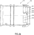
- Figur 5aFigure 5a
-
eine Seitenquerschnittsansicht der Presshülse aus
Figur 3 gemäß der Schnittlinie V-V ausFigur 5c , welche mit dem Halteelement ausFigur 4 verbunden ist;a side cross-sectional view of the compression sleeveFigure 3 according to the section line VVFigure 5c , which with the retaining elementFigure 4 connected is; - Figur 5bFigure 5b
-
eine perspektivische Ansicht der Anordnung aus
Figur 5a ;a perspective view of the arrangement fromFigure 5a ; - Figur 5cFigure 5c
-
eine axiale Ansicht der Anordnung aus den
Figuren 5a und5b , wobei die Schnittlinie V-V der inFigur 5a gezeigten Seitenquerschnittsansicht dargestellt ist;an axial view of the arrangement from FIGFigures 5a and5b , where the section line VV of the inFigure 5a shown is shown side cross-sectional view; - Figur 6Figure 6
- eine erfindungsgemäße Pressverbindung im unverpressten Zustand;a press connection according to the invention in the unpressed Status;
- Figur 7Figure 7
-
die Pressverbindung aus
Figur 6 im verpressten Zustand;the press connectionFigure 6 in the pressed state; - Figur 8Figure 8
- eine Detailansicht eines Vorsprungs.a detailed view of a protrusion.
In
Die Presshülse 10 umfasst einen zylindrischen Grundkörper 12, welcher eine Wandung 14 mit einer einheitlichen Dicke d aufweist.The
Der Grundkörper 12 bzw. dessen Wandung 14 umgibt einen Innenraum 16.The
Die Presshülse 10 weist in dem in
Die beiden Vorsprünge 18 und 20 sind hier als um den Außenumfang des Grundkörpers 12 ringartig herum verlaufende Vorsprünge 18 und 20 ausgebildet.The two
Die beiden Vorsprünge 18 und 20 sind mit dem Grundkörper 12 derart einstückig ausgebildet, dass die Vorsprünge 18 und 12 durch Materialfaltung der Wandung 14 des Grundkörpers 12 nach radial außen gebildet sind. Die Vorsprünge 18 und 20 weisen dabei Wellenberge 22 und 24 auf, an welche sich jeweils zu dem zylindrischen Grundkörper 12 verlaufende Flanken 26 und 28 bzw. 30 und 32 anschließen.The two
Zu dem Innenraum 16 des Grundkörpers 12 weisende Seiten der Flanken 26, 28, 30 und 32 liegen dabei derart an der jeweils gegenüberliegenden Flanke an, dass eine zu dem Innenraum 16 des Grundkörpers 12 weisende Seite des Vorsprungs 18 bzw. 20 im Wesentlichen frei von einer durch die Faltung der Wandung 14 entstehenden Nut ist. In dem in
An seinem in
An seinem in
Ferner ist in
Ein sich zwischen den beiden Vorsprünge 18 und 20 erstreckender Bereich 48 unterstützt zusammen mit den beiden Vorsprüngen 18 und 20 eine Positionierung eines nicht dargestellten Presswerkzeug, welches derart auf die Presshülse 10 einwirkt, dass diese zumindest teilweise nach radial innen, d.h. auf die Achse A zu, deformiert wird.A
In
Die Presshülse 110 weist einen zylindrischen Grundkörper 112 mit einer Wandung 114 auf.The
Einstückig mit der Wandung 114 sind analog zu der Presshülse 10 zwei Vorsprünge 118 und 120 ausgebildet.In one piece with the
Die Vorsprünge 118 und 120 sind als radial vollständig umlaufende Ringe ausgebildet.The
Die Vorsprünge 118 und 120 umfassen jeweils einen Wellenberg 122 und 124, wobei sich an den Wellenberg 122 zwei Flanken 126 und 128 und an den Wellenberg 124 zwei Flanken 130 und 132 anschließen.The
Im Gegensatz zu der Presshülse 10 stehen die zu einem Innenraum 116 des Grundkörpers 112 weisenden Seiten der Flanken 126 und 128 bzw. 130 und 132 nicht miteinander in Kontakt, sondern es ist ein Spalt 150 bzw. 152 zwischen ihnen ausgebildet, welcher hier in Längserstreckungsrichtung des Grundkörpers 112 gemessen etwa 0,05 mm beträgt. In dem in
In
Die Presshülse 210 weist einen zylindrischen Grundkörper 212 mit einer Wandung 214 auf.The
Einstückig mit der Wandung 214 sind analog zu der Presshülse 10 bzw. zu der Presshülse 110 zwei Vorsprünge 218 und 220 ausgebildet.In one piece with the
Die Vorsprünge 218 und 220 sind als radial vollständig umlaufende Ringe ausgebildet.The
Die Vorsprünge 218 und 220 umfassen jeweils einen Wellenberg 222 und 224, wobei sich an den Wellenberg 222 zwei Flanken 226 und 228 und an den Wellenberg 224 zwei Flanken 230 und 232 anschließen.The
Ein sich durch die Materialfaltung zur Bildung der Vorsprünge 218 bzw. 220 radial innerhalb des Wellenbergs 222 bzw. 224 ergebender Spalt 250 bzw. 252 ist in
An dem in
Die Verzahnungsstruktur 254 kann mit einer Verzahnungsstruktur 354, welche zu der Verzahnungsstruktur 254 passende Ausnehmungen 356 und Vorsprünge 358 umfasst, eines in
Das Halteelement 300 ist in dem hier dargestellten Ausführungsbeispiel als Spritzgußteil ausgebildet, welches in einem von der Presshülse 210 separaten Fertigungsschritt hergestellt worden ist. Das Halteelement 300 ist entsprechend aus einem hierfür geeigneten Kunststoff hergestellt.In the exemplary embodiment shown here, the holding
In den
Die in
An seinem von der Presshülse 210 weg weisenden Längsende weist dasAt its longitudinal end pointing away from the
Halteelement 300 eine Verbindungseinrichtung 360 in Form eines nach radial innen vorstehenden Vorsprungs 362 auf.Holding
Vermittels dieser Verbindungseinrichtung 360 kann die Presshülse 210 bzw. das Halteelement 300 mit einer Stützhülse verbunden werden, welche eine zu der Verbindungseinrichtung 360 des Halteelements 300 passende Verbindungseinrichtung, im Sinne einer Schnappverbindung, aufweist. Eine derartige Schnappverbindung ist auch in
Gemäß der in den
In
Das mit der Presshülse 10 verbundene Halteelement 300' greift über die oben erwähnte Verbindungseinrichtung 360 mit der Presshülse 400 ein.The holding
Wie weiter oben bereits beschrieben, kann in einen zwischen der Stützhülse 400 und der Presshülse 10 vorliegenden Spalt 402 ein Rohrelement 500 (s.
Die Stützhülse 400 weist eine Dichtung in Form von zwei O-Ringen 404 und 406 auf. Die beiden O-Ringe 404 und 406 sind an der Stützhülse 400 derart angeordnet, dass sie, bei mit der Stützhülse 400 über das Halteelement 300' verbundener Presshülse 10, unterhalb, d.h. in einer radialen Richtung innerhalb der beiden Vorsprünge 18 und 20 liegen.The
Die Stützhülse 400 weist ferner eine Struktur 408 auf, welche auf eine Deformation der Presshülse 10 und damit des zu verbindenden Rohrelements hin mit dem Rohrelement eingreift, so dass ein Abziehen des Rohrelements von der Stützhülse 400 erschwert bzw. verhindert werden kann.The
In
Dabei ist zu erkennen, dass ein zwischen die Stützhülse 400 und die Presshülse 10 eingeführtes Rohrelement 500 derart deformiert ist, dass es sich in die Struktur 408 hinein erstreckt, d.h. mit der Struktur 408 einen Formschluss eingeht. Ferner drückt das Rohrelement 500 im verpressten Zustand derart auf die beiden O-Ringe 404 und 406, dass sich deren ursprünglich kreisförmiger Querschnitt zu einem elliptischen Querschnitt verformt hat. Hierdurch ist eine fluiddichte Verbindung zwischen dem Rohrelement 500 und der Stützhülse 400 hergestellt, so dass durch das Rohrelement 500 strömendes Fluid nicht zwischen Stützhülse 400 und Rohrelement 500 austreten kann.It can be seen that a
In dem dargestellten Ausführungsbeispiel ist ferner zu erkennen, dass der Bereich der beiden Vorsprünge 18 und 20 der Presshülse 10 über dem Bereich der Dichtung, d.h. der beiden O-Ringe 404 und 406, liegt. Ein nicht dargestelltes Presswerkzeug wirkt derart auf die Presshülse 10 und damit auf das Rohrelement 500 ein, dass das Rohrelement 500 zuverlässig und fluiddicht auf die beiden O-Ringe 404 und 406 gedrückt wird.In the exemplary embodiment shown, it can also be seen that the area of the two
Anstatt des in
In
Ferner ist in
Claims (13)
- Press-fit sleeve (10, 110, 210) for connecting plastics pipes, comprising a cylindrical main body (12, 112, 212) having a uniform wall thickness (14, 114, 214) which surrounds an interior (16, 116) of the main body (12, 112, 212), the press-fit sleeve (10, 110, 210) comprising at least one projection (18, 118, 218; 20, 120, 220) which protrudes radially outwards from an outer circumference of the main body (12, 112, 212), the at least one projection (18, 118, 218; 20, 120, 220) being formed in one piece with the main body (12, 112, 212) by folding the material of the wall (14, 41, 42) of the main body (12, 112, 212), and the at least one projection (18, 118, 218; 20, 120, 220) forming a wave peak (22, 122, 222; 24, 124, 224) having two flanks (26, 28, 126, 128, 226, 228; 30, 32, 130, 132, 230, 232) connected by the wave peak (22, 122, 222; 24, 124, 224), characterised in that the mutually facing inner surfaces of said flanks are arranged at a distance of at most 1 mm, in particular of at most 0.5 mm, advantageously of at most 0.1 mm, from one another or are in contact with one another, and in that the mutually facing inner surfaces of the flanks (26, 28, 126, 128, 226, 228; 30, 32, 130, 230, 232) abut one another in a first portion (34a) adjacent to the wave peak (22, 122, 222; 24, 124, 224) and, in a second portion (34b) adjacent to the interior (16, 116) of the main body (12, 112, 212), have a spacing which increases in the direction of the interior (16, 116) of the main body (12, 112, 212).
- Press-fit sleeve (10, 110, 210) according to claim 1, characterised in that the press-fit sleeve (10, 110, 210) comprises at least two projections (18, 20, 118, 120, 218, 220) which are spaced apart from one another in a longitudinal extension direction of the main body (12, 112, 212).
- Press-fit sleeve (10, 110, 210) according to either claim 1 or claim 2, characterised in that at least one projection (18, 118, 218; 20, 120, 220) is extends completely around the outer circumference of the main body (12, 112, 212).
- Press-fit sleeve (10, 110, 210) according to any of the preceding claims, characterised in that the wall thickness (14, 114, 214) of the main body (12, 112, 212) has a value of 0.5 mm to 1.0 mm, in particular of 0.6 mm to 0.8 mm.
- Press-fit sleeve (10, 110, 210) according to any of the preceding claims, characterised in that outer surfaces of the flanks (26, 28, 126, 128, 226, 228; 30, 32, 130, 230, 232) of at least one projection (18, 118, 218; 20, 120, 220) extend substantially orthogonally to the cylindrical main body (12, 112, 212) of the press-fit sleeve (10, 110, 210).
- Press-fit sleeve (10, 110, 210) according to any of the preceding claims, characterised in that the press-fit sleeve (10, 110, 210) comprises a holding element (300), by means of which the press-fit sleeve (10, 110, 210) can be connected to a component which is not part of the press-fit sleeve (10, 110, 210).
- Press-fit sleeve (10, 110, 210) according to claim 6, characterised in that the holding element (300) is designed as an element which is separate from the main body (12, 112, 212) and can be connected to the main body (12, 112, 212).
- Press-fit sleeve (10, 110, 210) according to either claim 6 or claim 7, characterised in that the holding element (300) is designed as an injection-moulded part.
- Press-fit sleeve (10, 110, 210) according to any of claims 6 to 8, characterised in that the holding element (300) has a toothing structure (354) having projections (358) and recesses (356), which toothing structure is designed such that it can be brought into engagement with a toothing structure (254) of the press-fit sleeve (10, 110, 210) that has corresponding recesses (258) and projections (256).
- Press-fit connection, comprising a press-fit sleeve (10, 110, 210) according to any of claims 1 to 9 and a support sleeve (400) which is designed to be connected to a pipe (500), wherein the press-fit sleeve (10, 110, 210) can be brought into engagement with the support sleeve (400) in a predetermined position.
- Press-fit connection according to claim 10, characterised in that the engagement of the press-fit sleeve (10, 110, 210) or of a holding element (300) connected to the press-fit sleeve (10, 110, 210) with the support sleeve (400) comprises a snap-fit connection.
- Press-fit connection according to either claim 10 or claim 11, characterised in that the press-fit connection comprises a seal (404, 406) attached to the support sleeve, which is designed in particular as an O-ring and which is designed to seal a gap between the support sleeve and the pipe connected thereto, the region of the at least one projection (18, 118, 218; 20, 120, 220) of the main body (12, 112, 212) and the seal of the support sleeve being consecutive, viewed in a radial direction of the support sleeve.
- Press-fit connection according to any of claims 10 to 12, characterised in that the press-fit connection further comprises a structure (408) provided on the support sleeve, within which structure the radial extension of the support sleeve changes, comprising, for example, at least one rib or at least one groove, the region of the at least one projection (18, 118, 218; 20, 120, 220) of the main body (12, 112, 212) and the structure of the support sleeve being consecutive, viewed in a radial direction of the support sleeve.
Priority Applications (1)
| Application Number | Priority Date | Filing Date | Title |
|---|---|---|---|
| PL18734544T PL3645926T3 (en) | 2017-06-27 | 2018-06-26 | Press-fit sleeve |
Applications Claiming Priority (2)
| Application Number | Priority Date | Filing Date | Title |
|---|---|---|---|
| DE102017210844.4A DE102017210844A1 (en) | 2017-06-27 | 2017-06-27 | compression sleeve |
| PCT/EP2018/067167 WO2019002323A1 (en) | 2017-06-27 | 2018-06-26 | Press-fit sleeve |
Publications (2)
| Publication Number | Publication Date |
|---|---|
| EP3645926A1 EP3645926A1 (en) | 2020-05-06 |
| EP3645926B1 true EP3645926B1 (en) | 2021-04-07 |
Family
ID=62751001
Family Applications (1)
| Application Number | Title | Priority Date | Filing Date |
|---|---|---|---|
| EP18734544.2A Active EP3645926B1 (en) | 2017-06-27 | 2018-06-26 | Press-fit sleeve |
Country Status (8)
| Country | Link |
|---|---|
| EP (1) | EP3645926B1 (en) |
| CN (1) | CN110462274B (en) |
| DE (1) | DE102017210844A1 (en) |
| ES (1) | ES2870148T3 (en) |
| LT (1) | LT3645926T (en) |
| PL (1) | PL3645926T3 (en) |
| RU (1) | RU2721497C1 (en) |
| WO (1) | WO2019002323A1 (en) |
Cited By (1)
| Publication number | Priority date | Publication date | Assignee | Title |
|---|---|---|---|---|
| EP4166834A1 (en) * | 2021-10-13 | 2023-04-19 | Uponor Innovation AB | Assembly group for a press fitting, press fitting and assembly method for a press fitting |
Families Citing this family (1)
| Publication number | Priority date | Publication date | Assignee | Title |
|---|---|---|---|---|
| DE202020107328U1 (en) * | 2020-12-17 | 2022-03-18 | REHAU Industries SE & Co. KG | Pipe connection and connecting element for producing a pipe connection |
Family Cites Families (8)
| Publication number | Priority date | Publication date | Assignee | Title |
|---|---|---|---|---|
| DE10327503A1 (en) * | 2003-06-17 | 2005-01-05 | VETEC GmbH Verbindungstechnologie für Versorgungssysteme | Combination of a press fitting with a pressing tool, grouting fitting and compression sleeve |
| ATE230835T1 (en) * | 1997-02-07 | 2003-01-15 | Gottfried Mair | DEVICE FOR CLAMPING PIPELINE ELEMENTS |
| DE29900796U1 (en) * | 1998-04-03 | 1999-04-08 | Geberit Technik Ag | Device for connecting a pipe socket, tubular fitting or fittings to a pipe |
| ITMI20030010A1 (en) * | 2003-01-08 | 2004-07-09 | Antonio Romanelli | COMPRESSION FITTING FOR PIPES. |
| DE102006034101A1 (en) * | 2006-07-20 | 2008-02-07 | VETEC GmbH Verbindungstechnologie für Versorgungssysteme | Sleeve and combination of sleeve with pressing tool |
| US8439405B2 (en) * | 2010-06-18 | 2013-05-14 | The Gates Corporation | Crimped or swaged couplings for cable reinforced hoses |
| ITMI20121068A1 (en) | 2012-06-19 | 2013-12-20 | Ivar Spa | FITTING FOR THE CONNECTION OF PIPES, IN PARTICULAR OF FLEXIBLE PIPES |
| DE102014216184A1 (en) * | 2014-08-14 | 2016-02-18 | Fränkische Rohrwerke Gebr. Kirchner Gmbh & Co. Kg | compression sleeve |
-
2017
- 2017-06-27 DE DE102017210844.4A patent/DE102017210844A1/en not_active Withdrawn
-
2018
- 2018-06-26 CN CN201880020670.6A patent/CN110462274B/en not_active Expired - Fee Related
- 2018-06-26 ES ES18734544T patent/ES2870148T3/en active Active
- 2018-06-26 EP EP18734544.2A patent/EP3645926B1/en active Active
- 2018-06-26 LT LTEP18734544.2T patent/LT3645926T/en unknown
- 2018-06-26 PL PL18734544T patent/PL3645926T3/en unknown
- 2018-06-26 RU RU2019134431A patent/RU2721497C1/en active
- 2018-06-26 WO PCT/EP2018/067167 patent/WO2019002323A1/en unknown
Non-Patent Citations (1)
| Title |
|---|
| None * |
Cited By (2)
| Publication number | Priority date | Publication date | Assignee | Title |
|---|---|---|---|---|
| EP4166834A1 (en) * | 2021-10-13 | 2023-04-19 | Uponor Innovation AB | Assembly group for a press fitting, press fitting and assembly method for a press fitting |
| US11940063B2 (en) | 2021-10-13 | 2024-03-26 | Uponor Innovation Ab | Assembly group for a press fitting, press fitting and assembly method for a press fitting |
Also Published As
| Publication number | Publication date |
|---|---|
| CN110462274B (en) | 2021-08-06 |
| PL3645926T3 (en) | 2021-09-06 |
| WO2019002323A1 (en) | 2019-01-03 |
| DE102017210844A1 (en) | 2018-12-27 |
| CN110462274A (en) | 2019-11-15 |
| ES2870148T3 (en) | 2021-10-26 |
| RU2721497C1 (en) | 2020-05-19 |
| EP3645926A1 (en) | 2020-05-06 |
| LT3645926T (en) | 2021-07-12 |
Similar Documents
| Publication | Publication Date | Title |
|---|---|---|
| DE102006062894B4 (en) | protective cap | |
| EP2304303B1 (en) | Press-on fitting for a pipe, in particular plastic pipe, or plastic-metal composite pipe | |
| EP1939514B1 (en) | Connection device with tube supports for connecting fluid intake components | |
| EP2288836B1 (en) | Connector for fluid lines | |
| DE3815168C2 (en) | ||
| EP2463565B1 (en) | Pipe connection assembly | |
| EP0925467B1 (en) | Flexible hose sleeve | |
| EP2810855B1 (en) | Sealing stopper | |
| DE102012016592A1 (en) | blind rivet | |
| EP3645926B1 (en) | Press-fit sleeve | |
| EP2357390A2 (en) | Connection for a pipe | |
| DE102005061944A1 (en) | Tube for transporting fluid | |
| WO2008086763A1 (en) | Slave cylinder | |
| DE102015206461A1 (en) | Method for forming a tubular structural component for motor vehicle seats | |
| EP2985504B1 (en) | Fitting with crimping sleeve | |
| AT522951B1 (en) | Connector and connector assembly formed therefrom | |
| DE10200574C1 (en) | Socket connection for connecting pipelines comprises an inner part inserted with its insertion pin into an opening of an outer part and locked in place by a holding element which is elastically deformable in the radial direction | |
| EP3364088B1 (en) | Compression coupling for connecting a hose with a pipe nipple | |
| DE2700516A1 (en) | Socket or sleeve pipe coupling - has outer clamp ring with internal cones to successively deform outer coupling member | |
| EP3877105A1 (en) | Fastening unit | |
| EP1890069A2 (en) | Plug-in connector | |
| EP1944536A2 (en) | Crimp sleeve for crimping tubes together | |
| EP2982893B1 (en) | Tube clamp assembly | |
| EP3707393B1 (en) | Clip system | |
| EP0724109B1 (en) | Plug connector for high-pressure fluid lines |
Legal Events
| Date | Code | Title | Description |
|---|---|---|---|
| STAA | Information on the status of an ep patent application or granted ep patent |
Free format text: STATUS: UNKNOWN |
|
| STAA | Information on the status of an ep patent application or granted ep patent |
Free format text: STATUS: THE INTERNATIONAL PUBLICATION HAS BEEN MADE |
|
| PUAI | Public reference made under article 153(3) epc to a published international application that has entered the european phase |
Free format text: ORIGINAL CODE: 0009012 |
|
| STAA | Information on the status of an ep patent application or granted ep patent |
Free format text: STATUS: REQUEST FOR EXAMINATION WAS MADE |
|
| 17P | Request for examination filed |
Effective date: 20191119 |
|
| AK | Designated contracting states |
Kind code of ref document: A1 Designated state(s): AL AT BE BG CH CY CZ DE DK EE ES FI FR GB GR HR HU IE IS IT LI LT LU LV MC MK MT NL NO PL PT RO RS SE SI SK SM TR |
|
| AX | Request for extension of the european patent |
Extension state: BA ME |
|
| DAV | Request for validation of the european patent (deleted) | ||
| DAX | Request for extension of the european patent (deleted) | ||
| GRAP | Despatch of communication of intention to grant a patent |
Free format text: ORIGINAL CODE: EPIDOSNIGR1 |
|
| STAA | Information on the status of an ep patent application or granted ep patent |
Free format text: STATUS: GRANT OF PATENT IS INTENDED |
|
| INTG | Intention to grant announced |
Effective date: 20201103 |
|
| GRAS | Grant fee paid |
Free format text: ORIGINAL CODE: EPIDOSNIGR3 |
|
| GRAA | (expected) grant |
Free format text: ORIGINAL CODE: 0009210 |
|
| STAA | Information on the status of an ep patent application or granted ep patent |
Free format text: STATUS: THE PATENT HAS BEEN GRANTED |
|
| AK | Designated contracting states |
Kind code of ref document: B1 Designated state(s): AL AT BE BG CH CY CZ DE DK EE ES FI FR GB GR HR HU IE IS IT LI LT LU LV MC MK MT NL NO PL PT RO RS SE SI SK SM TR |
|
| REG | Reference to a national code |
Ref country code: GB Ref legal event code: FG4D Free format text: NOT ENGLISH |
|
| REG | Reference to a national code |
Ref country code: CH Ref legal event code: EP Ref country code: AT Ref legal event code: REF Ref document number: 1380123 Country of ref document: AT Kind code of ref document: T Effective date: 20210415 |
|
| REG | Reference to a national code |
Ref country code: DE Ref legal event code: R096 Ref document number: 502018004722 Country of ref document: DE |
|
| REG | Reference to a national code |
Ref country code: IE Ref legal event code: FG4D Free format text: LANGUAGE OF EP DOCUMENT: GERMAN |
|
| REG | Reference to a national code |
Ref country code: NL Ref legal event code: FP |
|
| REG | Reference to a national code |
Ref country code: EE Ref legal event code: FG4A Ref document number: E020900 Country of ref document: EE Effective date: 20210506 |
|
| REG | Reference to a national code |
Ref country code: ES Ref legal event code: FG2A Ref document number: 2870148 Country of ref document: ES Kind code of ref document: T3 Effective date: 20211026 |
|
| PG25 | Lapsed in a contracting state [announced via postgrant information from national office to epo] |
Ref country code: HR Free format text: LAPSE BECAUSE OF FAILURE TO SUBMIT A TRANSLATION OF THE DESCRIPTION OR TO PAY THE FEE WITHIN THE PRESCRIBED TIME-LIMIT Effective date: 20210407 Ref country code: FI Free format text: LAPSE BECAUSE OF FAILURE TO SUBMIT A TRANSLATION OF THE DESCRIPTION OR TO PAY THE FEE WITHIN THE PRESCRIBED TIME-LIMIT Effective date: 20210407 Ref country code: BG Free format text: LAPSE BECAUSE OF FAILURE TO SUBMIT A TRANSLATION OF THE DESCRIPTION OR TO PAY THE FEE WITHIN THE PRESCRIBED TIME-LIMIT Effective date: 20210707 |
|
| PG25 | Lapsed in a contracting state [announced via postgrant information from national office to epo] |
Ref country code: PT Free format text: LAPSE BECAUSE OF FAILURE TO SUBMIT A TRANSLATION OF THE DESCRIPTION OR TO PAY THE FEE WITHIN THE PRESCRIBED TIME-LIMIT Effective date: 20210809 Ref country code: RS Free format text: LAPSE BECAUSE OF FAILURE TO SUBMIT A TRANSLATION OF THE DESCRIPTION OR TO PAY THE FEE WITHIN THE PRESCRIBED TIME-LIMIT Effective date: 20210407 Ref country code: SE Free format text: LAPSE BECAUSE OF FAILURE TO SUBMIT A TRANSLATION OF THE DESCRIPTION OR TO PAY THE FEE WITHIN THE PRESCRIBED TIME-LIMIT Effective date: 20210407 Ref country code: LV Free format text: LAPSE BECAUSE OF FAILURE TO SUBMIT A TRANSLATION OF THE DESCRIPTION OR TO PAY THE FEE WITHIN THE PRESCRIBED TIME-LIMIT Effective date: 20210407 Ref country code: NO Free format text: LAPSE BECAUSE OF FAILURE TO SUBMIT A TRANSLATION OF THE DESCRIPTION OR TO PAY THE FEE WITHIN THE PRESCRIBED TIME-LIMIT Effective date: 20210707 Ref country code: GR Free format text: LAPSE BECAUSE OF FAILURE TO SUBMIT A TRANSLATION OF THE DESCRIPTION OR TO PAY THE FEE WITHIN THE PRESCRIBED TIME-LIMIT Effective date: 20210708 Ref country code: IS Free format text: LAPSE BECAUSE OF FAILURE TO SUBMIT A TRANSLATION OF THE DESCRIPTION OR TO PAY THE FEE WITHIN THE PRESCRIBED TIME-LIMIT Effective date: 20210807 |
|
| REG | Reference to a national code |
Ref country code: DE Ref legal event code: R097 Ref document number: 502018004722 Country of ref document: DE |
|
| PG25 | Lapsed in a contracting state [announced via postgrant information from national office to epo] |
Ref country code: MC Free format text: LAPSE BECAUSE OF FAILURE TO SUBMIT A TRANSLATION OF THE DESCRIPTION OR TO PAY THE FEE WITHIN THE PRESCRIBED TIME-LIMIT Effective date: 20210407 Ref country code: CZ Free format text: LAPSE BECAUSE OF FAILURE TO SUBMIT A TRANSLATION OF THE DESCRIPTION OR TO PAY THE FEE WITHIN THE PRESCRIBED TIME-LIMIT Effective date: 20210407 Ref country code: DK Free format text: LAPSE BECAUSE OF FAILURE TO SUBMIT A TRANSLATION OF THE DESCRIPTION OR TO PAY THE FEE WITHIN THE PRESCRIBED TIME-LIMIT Effective date: 20210407 Ref country code: SM Free format text: LAPSE BECAUSE OF FAILURE TO SUBMIT A TRANSLATION OF THE DESCRIPTION OR TO PAY THE FEE WITHIN THE PRESCRIBED TIME-LIMIT Effective date: 20210407 Ref country code: RO Free format text: LAPSE BECAUSE OF FAILURE TO SUBMIT A TRANSLATION OF THE DESCRIPTION OR TO PAY THE FEE WITHIN THE PRESCRIBED TIME-LIMIT Effective date: 20210407 Ref country code: SK Free format text: LAPSE BECAUSE OF FAILURE TO SUBMIT A TRANSLATION OF THE DESCRIPTION OR TO PAY THE FEE WITHIN THE PRESCRIBED TIME-LIMIT Effective date: 20210407 |
|
| REG | Reference to a national code |
Ref country code: CH Ref legal event code: PL |
|
| PLBE | No opposition filed within time limit |
Free format text: ORIGINAL CODE: 0009261 |
|
| STAA | Information on the status of an ep patent application or granted ep patent |
Free format text: STATUS: NO OPPOSITION FILED WITHIN TIME LIMIT |
|
| 26N | No opposition filed |
Effective date: 20220110 |
|
| PG25 | Lapsed in a contracting state [announced via postgrant information from national office to epo] |
Ref country code: LU Free format text: LAPSE BECAUSE OF NON-PAYMENT OF DUE FEES Effective date: 20210626 |
|
| PG25 | Lapsed in a contracting state [announced via postgrant information from national office to epo] |
Ref country code: LI Free format text: LAPSE BECAUSE OF NON-PAYMENT OF DUE FEES Effective date: 20210630 Ref country code: IE Free format text: LAPSE BECAUSE OF NON-PAYMENT OF DUE FEES Effective date: 20210626 Ref country code: CH Free format text: LAPSE BECAUSE OF NON-PAYMENT OF DUE FEES Effective date: 20210630 |
|
| PG25 | Lapsed in a contracting state [announced via postgrant information from national office to epo] |
Ref country code: IS Free format text: LAPSE BECAUSE OF FAILURE TO SUBMIT A TRANSLATION OF THE DESCRIPTION OR TO PAY THE FEE WITHIN THE PRESCRIBED TIME-LIMIT Effective date: 20210807 Ref country code: AL Free format text: LAPSE BECAUSE OF FAILURE TO SUBMIT A TRANSLATION OF THE DESCRIPTION OR TO PAY THE FEE WITHIN THE PRESCRIBED TIME-LIMIT Effective date: 20210407 |
|
| PG25 | Lapsed in a contracting state [announced via postgrant information from national office to epo] |
Ref country code: IT Free format text: LAPSE BECAUSE OF FAILURE TO SUBMIT A TRANSLATION OF THE DESCRIPTION OR TO PAY THE FEE WITHIN THE PRESCRIBED TIME-LIMIT Effective date: 20210407 |
|
| PG25 | Lapsed in a contracting state [announced via postgrant information from national office to epo] |
Ref country code: CY Free format text: LAPSE BECAUSE OF FAILURE TO SUBMIT A TRANSLATION OF THE DESCRIPTION OR TO PAY THE FEE WITHIN THE PRESCRIBED TIME-LIMIT Effective date: 20210407 |
|
| PG25 | Lapsed in a contracting state [announced via postgrant information from national office to epo] |
Ref country code: HU Free format text: LAPSE BECAUSE OF FAILURE TO SUBMIT A TRANSLATION OF THE DESCRIPTION OR TO PAY THE FEE WITHIN THE PRESCRIBED TIME-LIMIT; INVALID AB INITIO Effective date: 20180626 |
|
| PGFP | Annual fee paid to national office [announced via postgrant information from national office to epo] |
Ref country code: NL Payment date: 20230620 Year of fee payment: 6 Ref country code: LT Payment date: 20230615 Year of fee payment: 6 Ref country code: FR Payment date: 20230628 Year of fee payment: 6 Ref country code: EE Payment date: 20230628 Year of fee payment: 6 Ref country code: DE Payment date: 20230531 Year of fee payment: 6 |
|
| PGFP | Annual fee paid to national office [announced via postgrant information from national office to epo] |
Ref country code: TR Payment date: 20230620 Year of fee payment: 6 Ref country code: PL Payment date: 20230619 Year of fee payment: 6 Ref country code: AT Payment date: 20230621 Year of fee payment: 6 |
|
| PGFP | Annual fee paid to national office [announced via postgrant information from national office to epo] |
Ref country code: BE Payment date: 20230620 Year of fee payment: 6 |
|
| PGFP | Annual fee paid to national office [announced via postgrant information from national office to epo] |
Ref country code: GB Payment date: 20230622 Year of fee payment: 6 Ref country code: ES Payment date: 20230830 Year of fee payment: 6 |