EP3645455B1 - Process for high-yield production of hydrogen from a synthesis gas, and debottlenecking of an existing unit - Google Patents
Process for high-yield production of hydrogen from a synthesis gas, and debottlenecking of an existing unit Download PDFInfo
- Publication number
- EP3645455B1 EP3645455B1 EP17754188.5A EP17754188A EP3645455B1 EP 3645455 B1 EP3645455 B1 EP 3645455B1 EP 17754188 A EP17754188 A EP 17754188A EP 3645455 B1 EP3645455 B1 EP 3645455B1
- Authority
- EP
- European Patent Office
- Prior art keywords
- hydrogen
- psa
- waste
- production
- ehs
- Prior art date
- Legal status (The legal status is an assumption and is not a legal conclusion. Google has not performed a legal analysis and makes no representation as to the accuracy of the status listed.)
- Active
Links
Images
Classifications
-
- C—CHEMISTRY; METALLURGY
- C01—INORGANIC CHEMISTRY
- C01B—NON-METALLIC ELEMENTS; COMPOUNDS THEREOF; METALLOIDS OR COMPOUNDS THEREOF NOT COVERED BY SUBCLASS C01C
- C01B3/00—Hydrogen; Gaseous mixtures containing hydrogen; Separation of hydrogen from mixtures containing it; Purification of hydrogen
- C01B3/02—Production of hydrogen or of gaseous mixtures containing a substantial proportion of hydrogen
- C01B3/32—Production of hydrogen or of gaseous mixtures containing a substantial proportion of hydrogen by reaction of gaseous or liquid organic compounds with gasifying agents, e.g. water, carbon dioxide, air
- C01B3/34—Production of hydrogen or of gaseous mixtures containing a substantial proportion of hydrogen by reaction of gaseous or liquid organic compounds with gasifying agents, e.g. water, carbon dioxide, air by reaction of hydrocarbons with gasifying agents
- C01B3/48—Production of hydrogen or of gaseous mixtures containing a substantial proportion of hydrogen by reaction of gaseous or liquid organic compounds with gasifying agents, e.g. water, carbon dioxide, air by reaction of hydrocarbons with gasifying agents followed by reaction of water vapour with carbon monoxide
-
- C—CHEMISTRY; METALLURGY
- C01—INORGANIC CHEMISTRY
- C01B—NON-METALLIC ELEMENTS; COMPOUNDS THEREOF; METALLOIDS OR COMPOUNDS THEREOF NOT COVERED BY SUBCLASS C01C
- C01B3/00—Hydrogen; Gaseous mixtures containing hydrogen; Separation of hydrogen from mixtures containing it; Purification of hydrogen
- C01B3/50—Separation of hydrogen or hydrogen containing gases from gaseous mixtures, e.g. purification
- C01B3/56—Separation of hydrogen or hydrogen containing gases from gaseous mixtures, e.g. purification by contacting with solids; Regeneration of used solids
-
- C—CHEMISTRY; METALLURGY
- C01—INORGANIC CHEMISTRY
- C01B—NON-METALLIC ELEMENTS; COMPOUNDS THEREOF; METALLOIDS OR COMPOUNDS THEREOF NOT COVERED BY SUBCLASS C01C
- C01B2203/00—Integrated processes for the production of hydrogen or synthesis gas
- C01B2203/02—Processes for making hydrogen or synthesis gas
- C01B2203/0205—Processes for making hydrogen or synthesis gas containing a reforming step
- C01B2203/0227—Processes for making hydrogen or synthesis gas containing a reforming step containing a catalytic reforming step
- C01B2203/0233—Processes for making hydrogen or synthesis gas containing a reforming step containing a catalytic reforming step the reforming step being a steam reforming step
-
- C—CHEMISTRY; METALLURGY
- C01—INORGANIC CHEMISTRY
- C01B—NON-METALLIC ELEMENTS; COMPOUNDS THEREOF; METALLOIDS OR COMPOUNDS THEREOF NOT COVERED BY SUBCLASS C01C
- C01B2203/00—Integrated processes for the production of hydrogen or synthesis gas
- C01B2203/02—Processes for making hydrogen or synthesis gas
- C01B2203/0283—Processes for making hydrogen or synthesis gas containing a CO-shift step, i.e. a water gas shift step
-
- C—CHEMISTRY; METALLURGY
- C01—INORGANIC CHEMISTRY
- C01B—NON-METALLIC ELEMENTS; COMPOUNDS THEREOF; METALLOIDS OR COMPOUNDS THEREOF NOT COVERED BY SUBCLASS C01C
- C01B2203/00—Integrated processes for the production of hydrogen or synthesis gas
- C01B2203/04—Integrated processes for the production of hydrogen or synthesis gas containing a purification step for the hydrogen or the synthesis gas
- C01B2203/042—Purification by adsorption on solids
- C01B2203/043—Regenerative adsorption process in two or more beds, one for adsorption, the other for regeneration
-
- C—CHEMISTRY; METALLURGY
- C01—INORGANIC CHEMISTRY
- C01B—NON-METALLIC ELEMENTS; COMPOUNDS THEREOF; METALLOIDS OR COMPOUNDS THEREOF NOT COVERED BY SUBCLASS C01C
- C01B2203/00—Integrated processes for the production of hydrogen or synthesis gas
- C01B2203/04—Integrated processes for the production of hydrogen or synthesis gas containing a purification step for the hydrogen or the synthesis gas
- C01B2203/0465—Composition of the impurity
- C01B2203/047—Composition of the impurity the impurity being carbon monoxide
-
- C—CHEMISTRY; METALLURGY
- C01—INORGANIC CHEMISTRY
- C01B—NON-METALLIC ELEMENTS; COMPOUNDS THEREOF; METALLOIDS OR COMPOUNDS THEREOF NOT COVERED BY SUBCLASS C01C
- C01B2203/00—Integrated processes for the production of hydrogen or synthesis gas
- C01B2203/04—Integrated processes for the production of hydrogen or synthesis gas containing a purification step for the hydrogen or the synthesis gas
- C01B2203/0465—Composition of the impurity
- C01B2203/0475—Composition of the impurity the impurity being carbon dioxide
-
- C—CHEMISTRY; METALLURGY
- C01—INORGANIC CHEMISTRY
- C01B—NON-METALLIC ELEMENTS; COMPOUNDS THEREOF; METALLOIDS OR COMPOUNDS THEREOF NOT COVERED BY SUBCLASS C01C
- C01B2203/00—Integrated processes for the production of hydrogen or synthesis gas
- C01B2203/12—Feeding the process for making hydrogen or synthesis gas
- C01B2203/1258—Pre-treatment of the feed
- C01B2203/1264—Catalytic pre-treatment of the feed
- C01B2203/127—Catalytic desulfurisation
-
- C—CHEMISTRY; METALLURGY
- C01—INORGANIC CHEMISTRY
- C01B—NON-METALLIC ELEMENTS; COMPOUNDS THEREOF; METALLOIDS OR COMPOUNDS THEREOF NOT COVERED BY SUBCLASS C01C
- C01B2203/00—Integrated processes for the production of hydrogen or synthesis gas
- C01B2203/14—Details of the flowsheet
- C01B2203/148—Details of the flowsheet involving a recycle stream to the feed of the process for making hydrogen or synthesis gas
Definitions
- the present invention relates to a process for producing hydrogen by reforming hydrocarbons, it also relates to a method of debottlenecking an existing hydrogen production facility, as well as a hydrogen production facility.
- Hydrogen production systems are most often based on the reforming of light hydrocarbons - by light hydrocarbons we most often mean methane, generally in the form of natural gas or bio methane, but also naphtha, methanol among others - they also use partial oxidation or auto thermal reforming processes; these production systems generate gas mixtures mainly containing hydrogen and carbon monoxide, but also carbon dioxide, water and trace compounds, these mixtures being known under the name of synthesis gas or syngas. Steam reforming is among these systems the most commonly used, it makes it possible to produce around 90% of the hydrogen currently consumed in the world, both to meet industrial needs and those linked to mobility.
- the invention presented below makes it possible to increase the efficiency of recovery of the hydrogen produced by conventional hydrogen production plants, by a value of between approximately 75% and 90% depending on the size of the installation and operating parameters to a value close to 99%, whatever the size of the installation.
- these installations typically include a unit for purifying hydrogen by pressure swing adsorption, more commonly identified as a hydrogen PSA or PSA H 2 unit (acronym of the English expression "pressure swing adsorption).
- the pressurized feedstock (natural gas, mixture of light hydrocarbons or other feed of the same type) is, depending on its composition, desulphurized, optionally pre-reformed, then it is reformed to produce a synthesis gas essentially containing H 2 , CO 2 , CO, with smaller amounts of CH 4 and N 2 as well as water vapor.
- synthesis gas When the synthesis gas is produced with a view to the final production of hydrogen, it then generally passes through one or more reactors called "shift" reactors where the carbon monoxide is converted into carbon dioxide by reaction with steam. and producing additional hydrogen.
- the PSA purification process provides a product of very high quality, it only makes it possible to recover around 75 to 90% of the hydrogen entering the PSA depending on the complexity of the PSA cycle (in particular the number of balances and adsorbers), also a function of the flow rate. To compensate for the loss of hydrogen in the PSA, it is therefore necessary to increase the size of the reformer to achieve the desired production.
- the reformer must also be able to operate at a high pressure, of the order of 25 bars to produce a syngas at a pressure sufficient for the downstream treatment, and in particular to optimize the operation of the PSA, this further increases the cost of reformer.
- the purge gases from the PSA are used as fuel gas for the reformer.
- Table 1 Classic PSA yield as a function of H ⁇ sub> 2 ⁇ /sub> production PSA (number of adsorbers) 4 5 6 8 10 H 2 flow (Nm 3 / h) 100-2000 2000-10000 10000-25000 20000-50000 50,000 + H 2 PSA yield 78-80% 82-84% 84-86% 85-87% 87-89%
- the PSA residue Due to the limited yield of the PSA, the PSA residue therefore has a high hydrogen content - as illustrated by the example reported in Table 2 presented below - and all the more so when the installation is large. scaled down. While this hydrogen can be recovered as a product, it generally has a much higher value than it can have as a fuel.
- recovering (of) the hydrogen from the gaseous waste of the PSA can make it possible to better exploit the synthesis gas produced by the reformer, and can also make it possible to meet new hydrogen needs without resorting to expensive solutions. and of limited efficacy as enumerated above, as long as this additional hydrogen can be produced under conditions of satisfactory purity and cost.
- the solution consists in supplying an electrochemical cell from said low pressure gaseous waste so as to separate additional hydrogen from said low pressure gaseous waste, the additional hydrogen stream produced using the PEM membrane is recovered and combined with high pressure hydrogen produced by the PSA unit with the result of increasing the quantity of hydrogen produced by the installation.
- He is also known from EP 2 141 119 A1 a process for the production of hydrogen by reforming and purification of hydrogen by PSA with joint recovery of carbon dioxide, for this, the PSA residue is treated in two successive different membranes, one to separate carbon dioxide, and the other to separate from the hydrogen, with recycling of the permeate of the hydrogen membrane enriched in hydrogen at the inlet of the PSA.
- He is also known from FR 2 877 939 A1 a process for a combined production of hydrogen and carbon dioxide in which the residual PSA is treated to produce a fluid enriched in carbon dioxide by successive condensations / separations and treatment of non-condensables to produce a permeate rich in hydrogen which can be recycled at the PSA
- the invention therefore aims to increase the hydrogen yield of a hydrogen production plant - by reforming natural gas (or comparable feed) and purifying the hydrogen by PSA - while preserving the purity of the product and at a lower cost. .
- the solution according to the invention consists in installing an electrochemical hydrogen purification system / cell operating using a proton exchange membrane - a so-called EHS system (acronym for the corresponding English expression Electrochemical Hydrogen Separation) - installed on the residual gas from the PSA (fluid 14 in the figures) and combined with a recirculation of the purified and compressed hydrogen (mechanical or electrochemical compression combined with the separation step in the same electrochemical cell) at the inlet of the PSA so to increase the overall efficiency of an existing installation, while maintaining the quality of the hydrogen produced.
- EHS system Electrochemical Hydrogen Separation
- the invention relates to a method of debottlenecking an installation producing hydrogen comprising a module for generating a synthesis gas by reforming from light hydrocarbons, optionally a shift module for enrichment in hydrogen and carbon dioxide by converting the carbon monoxide contained in the synthesis gas with water vapor, a PSA-H 2 unit for the purification of hydrogen and the production of a gas stream high pressure ultra pure hydrogen, in particular in accordance with the ISO14687 standard with associated production of a low pressure gaseous waste (PSA waste), the two major constituents of which are carbon dioxide and hydrogen, a method according to which we installs an electrochemical hydrogen purification cell on the low pressure gaseous waste of the PSA so as to separate hydrogen and a waste (EHS cell waste) depleted in hydrogen from said PSA waste, the hydrogen being recovered for form an additional flow of hydrogen which is compressed to a pressure between 8 and 25 bar and sent in whole or in part to the inlet of the PSA unit to increase the production of hydrogen from the installation while maintaining unchanged the purity of
- the production of hydrogen from the installation is increased while maintaining the purity of the hydrogen produced by the PSA unit unchanged.
- the installation's purification module - combining the PSA and the electrochemical hydrogen separation cell (EHS system) installed on the residual with recirculation at the PSA inlet - then ensures an overall hydrogen yield of the nearby installation 99% when all of the additional hydrogen flow from the cell is sent to feed the PSA.
- the purity of the hydrogen produced at the outlet of the PSA remains unchanged.
- the invention relates to a process for producing hydrogen, the overall yield of which is optimized from its design. Indeed, the installation of an EHS cell on the PSA residue can also be done during the installation of a new installation, it allows in this case to have directly a very puroptimized hydrogen yield, without having to over-size the components located upstream of the PSA.
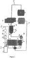
- a hydrocarbon feedstock 1 intended to produce hydrogen is subjected to an - optional - compression stage 2a, then to a desulfurization stage 2b and to an - optional - pre-reforming stage 2c, before being mixed - after preheating not shown - with water vapor at the mixing point 3 and then introduced into a steam reforming reactor 4 where it is reformed at high temperature thanks to the external heat supplied by burners 5 installed in the walls of the reactor 4 - the burners that can be installed in the side walls, installed on the terrace, in the vault or on the floor depending on the manufacturers - to produce a synthesis gas 6, a mixture essentially containing hydrogen and carbon oxides - mainly CO.
- Synthesis gas 6 also called syngas is produced at high temperature (of the order of 600 ° C 800 ° C) and pressure, it is then enriched in H 2 and CO 2 in a shift 7 reactor by conversion of CO by the excess water vapor present in the syngas to produce the syngas enriched in hydrogen 8.
- the H 2 yield of the PSA is of the order of 78-80% for 4 adsorbers; as reported in Table I, it increases in the case of large installations reaching 88-89% for 10 adsorbers for installations producing 50,000Nm 3 / h or more.
- the PSA 12 unit produces ultra pure hydrogen 13 under pressure, as well as a low pressure gaseous waste 14 which brings together all the components present in more hydrogen in syngas 11 feeding the PSA, i.e. the very majority CO 2 , but also the CO, residual CH 4 , water vapor, nitrogen, but also next to these gases, hydrogen in proportion all the more important as the installation is small.
- the hydrogen produced 13 passes (optionally) into a production buffer tank (not referenced) in order to smooth the pressure and flow variations linked to the cycles of the PSA.
- a buffer capacity 14 is installed on the waste gas from the PSA in order to smooth out the variations in pressure, flow rate and composition of the waste gas which could affect the correct operation of the burners of the reforming furnace.
- the waste gas is used as a fuel gas, in particular for heating the reformer, because of its hydrogen and methane contents.
- the diagram does not reproduce the complexity of the installation; among the elements of the overall process - not necessary for understanding the invention - only a few are present (referenced or not): heat exchanger 9b between the syngas 8 and water with recovery of the condensates 10 upstream of the PSA , supply and preheating of the combustion air, supply of water to the installation with heating in the convection chamber of the reformer against the fumes and in the exchanger 9b against the syngas, etc.
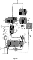
- the diagram of the figure 2 represents an installation deduced from that of the figure 1 , but which has been debottlenecked in application of the invention.
- the elements of the figure 1 that we find on the figure 2 bear the same references, in particular all the fluids and means participating in the generation of synthesis gas upstream of the purification of the hydrogen.
- the hydrocarbon feedstock 1 is here also compressed, desulfurized and pre-reformed in 2a, 2b, 2c before being mixed with the steam at the mixing point 3 and then introduced into the reforming reactor at the steam 4 where it is reformed at high temperature thanks to the external heat supplied by the burners 5 to produce the synthesis gas (or syngas) 6.
- the syngas at elevated temperature and pressure is enriched in H 2 and CO 2 in a shift reactor 7 by reaction between water vapor and the CO present in the syngas.
- the syngas 11 enriched in H 2 and CO 2 is sent to the PSA unit.
- the PSA unit 12 produces very high purity hydrogen 13 under pressure, as well as the residual low pressure gaseous PSA 14.
- the hydrogen produced 13 passes (optionally) into a production buffer tank (not referenced) in order to smooth the pressure and flow variations linked to the cycles of the PASA
- a buffer capacity 14 is installed on the residual gas of the PSA in order to smooth the variations in pressure, flow rate and composition of the PSA waste gas.
- the waste gas 14 feeds an electrochemical purification cell 15 which operates as follows: the electrochemical cell separates the constituents of the waste 14 from the hydrogen and thus produces hydrogen 16 as well as a second gas stream 20 essentially containing all of the gases present in the PSA residue 14 with only a few percent of hydrogen.
- This second gas stream 20 (identified as EHS cell waste) is - in the example - used as fuel gas for heating the reformer. Other known uses are possible depending on the circumstances and needs.
- the hydrogen 16 is compressed at 17, the gas thus compressed 18 is combined with the syngas 11 to form a new feed gas 19 for the PSA 12.
- the estimated compression power is 51.64 KW
- the estimated EHS power is 23.24 KW.
- the overall Hydrogen efficiency is 99% (Table 3C: fluid 13 values / 11 fluid values) with an EHS Hydrogen efficiency of 95% (Table 3C: 16 fluid values / 14 fluid values), and a PSA Hydrogen efficiency of 84% (Table 3C: flux13 values / flux 19 values).
- the flow rate of hydrogen produced (at identical purity) therefore increases from 610 Nm 3 / h to 756 Nm 3 / h, i.e. an increase of 24 % for a maximum additional electricity requirement of 75kW.
- This additional electricity requirement can be advantageously reduced (to around 40KW) by combining the electrochemical purification step and the compression step in the same electrochemical cell.
- the hydrogen separation by PEM proton exchange membrane - implemented in EHS cells - applied to the separation of the hydrogen contained in the gaseous waste from the PSA works as follows: the gaseous waste from the PSA, available at a temperature of the order of room temperature and at a pressure 300 to 500 mbar above atmospheric pressure supplies an electrochemical cell which contains electrodes covered with catalyst on either side of a membrane. As electric current passes through the electrodes, the PEM membrane used in the EHS cell allows hydrogen - in the form of H 3 O + - to pass selectively through the membrane, so that pure hydrogen is recovered from the other side.
- E cathode - E anode - R ⁇ T 2 ⁇ F ln P H 2 Cathode P H 2 Anode
- the membrane thereby creates a second stream containing the other compounds of the PSA residue, which cannot cross the membrane which rejects them; they form the "rejected" current.
- This rejected stream - this is stream 20 of the figure 2 and of the example, it is therefore the waste gas from the EHS within the meaning of the invention. It may, depending on its composition, be effectively rejected, or treated and / or reused in other processes, or used as fuel in the reforming furnace as shown in the example presented.
- the hydrogen thus recovered at the outlet of the EHS cell, it does not have sufficient purity to be added to the hydrogen produced by the PSA, the quality of which it would greatly degrade, after compression. suitable for recycling to power the PSA. Note that hydrogen can also be simultaneously compressed
Description
La présente invention concerne un procédé de production d'hydrogène par reformage d'hydrocarbures, elle concerne aussi une méthode de dégoulottage d'une installation de production d'hydrogène existante, ainsi qu'une installation de production d'hydrogène.The present invention relates to a process for producing hydrogen by reforming hydrocarbons, it also relates to a method of debottlenecking an existing hydrogen production facility, as well as a hydrogen production facility.
Les systèmes de production d'hydrogène sont le plus souvent basés sur le reformage d'hydrocarbures légers - par hydrocarbures légers, on entend le plus souvent du méthane, généralement sous la forme de gaz naturel ou de bio méthane, mais aussi du naphta, du méthanol entre autres - ils font aussi appel aux procédés d'oxydation partielle ou de reformage auto thermique ; ces systèmes de production génèrent des mélanges gazeux contenant très majoritairement de l'hydrogène et du monoxyde de carbone, mais aussi du dioxyde de carbone, de l'eau ainsi que des composés trace, ces mélanges étant connus sous le nom de gaz de synthèse ou syngas. Le reformage à la vapeur est parmi ces systèmes le plus couramment utilisé, il permet de produire de l'ordre de 90% de l'hydrogène actuellement consommé dans le monde, autant pour satisfaire les besoins industriels que ceux liés à la mobilité.Hydrogen production systems are most often based on the reforming of light hydrocarbons - by light hydrocarbons we most often mean methane, generally in the form of natural gas or bio methane, but also naphtha, methanol among others - they also use partial oxidation or auto thermal reforming processes; these production systems generate gas mixtures mainly containing hydrogen and carbon monoxide, but also carbon dioxide, water and trace compounds, these mixtures being known under the name of synthesis gas or syngas. Steam reforming is among these systems the most commonly used, it makes it possible to produce around 90% of the hydrogen currently consumed in the world, both to meet industrial needs and those linked to mobility.
Les installations correspondent la plupart du temps à des investissements faits en lien avec des contrats de fourniture de gaz longue durée, et il est très difficile initialement de prévoir ce que sera l'évolution de la demande (nouveaux clients et/ou augmentation des besoins des clients existants), de sorte que se pose fréquemment le problème d'augmenter la capacité de production d'hydrogène de l'installation tout en minimisant l'investissement nécessaire pour y parvenir.Most of the time, the installations correspond to investments made in connection with long-term gas supply contracts, and it is very difficult initially to predict what the evolution of demand will be (new customers and / or increase in customer needs). existing customers), so that the problem frequently arises of increasing the facility's hydrogen production capacity while minimizing the investment required to achieve this.
L'invention présentée ci-après permet d'augmenter le rendement de récupération de l'hydrogène produit par des installations de production d'hydrogène conventionnelles, d'une valeur comprise entre environ 75% et 90% en fonction de la taille de l'installation et des paramètres opératoires à une valeur proche de 99%, quelle que soit la taille de l'installation.The invention presented below makes it possible to increase the efficiency of recovery of the hydrogen produced by conventional hydrogen production plants, by a value of between approximately 75% and 90% depending on the size of the installation and operating parameters to a value close to 99%, whatever the size of the installation.
En effet, ces installations comprennent typiquement une unité de purification d'hydrogène par adsorption à pression modulée, plus couramment identifiée comme unité PSA hydrogène ou PSA H2 (acronyme de l'expression anglaise « pressure swing adsorption).In fact, these installations typically include a unit for purifying hydrogen by pressure swing adsorption, more commonly identified as a hydrogen PSA or PSA H 2 unit (acronym of the English expression "pressure swing adsorption).
Le schéma classique d'une installation de production d'hydrogène par reformage de méthane à la vapeur (SMR) est reproduit sur la
La charge d'alimentation sous pression (gaz naturel, mélange d'hydrocarbures légers ou autre charge de même type) est, selon sa composition, désulfurée, optionnellement pré reformée, puis elle est reformée pour produire un gaz de synthèse contenant essentiellement H2, CO2, CO, avec en quantités moindres CH4 et N2 ainsi que de la vapeur d'eau. Lorsque le gaz de synthèse est produit dans une optique de production finale d'hydrogène, il passe ensuite en général dans un ou plusieurs réacteurs dits réacteurs de « shift » où le monoxyde de carbone est converti en dioxyde de carbone par réaction avec de la vapeur et en produisant un supplément d'hydrogène.The pressurized feedstock (natural gas, mixture of light hydrocarbons or other feed of the same type) is, depending on its composition, desulphurized, optionally pre-reformed, then it is reformed to produce a synthesis gas essentially containing H 2 , CO 2 , CO, with smaller amounts of CH 4 and N 2 as well as water vapor. When the synthesis gas is produced with a view to the final production of hydrogen, it then generally passes through one or more reactors called "shift" reactors where the carbon monoxide is converted into carbon dioxide by reaction with steam. and producing additional hydrogen.
Le gaz de synthèse en sortie du réacteur de shift, et après refroidissement à température ambiante et élimination des condensats de procédé contient approximativement de 75 à 82% d'hydrogène, 2 à 3% de monoxyde de carbone, 10 à 20% de dioxyde de carbone, 0.3 à 4% de méthane, ainsi que des composés traces, dont selon les cas de l'azote.The synthesis gas leaving the shift reactor, and after cooling to room temperature and removal of process condensates, contains approximately 75 to 82% hydrogen, 2 to 3% carbon monoxide, 10 to 20% carbon dioxide. carbon, 0.3 to 4% methane, as well as trace compounds, including nitrogen, depending on the case.
Afin de produire de l'hydrogène pur, une purification complémentaire est ensuite réalisée qui utilise la technologie PSA qui permet de produire un courant gazeux d'hydrogène ultra pur.In order to produce pure hydrogen, an additional purification is then carried out which uses the PSA technology which makes it possible to produce a gaseous stream of ultra pure hydrogen.
Cependant, si le procédé de purification par PSA fournit un produit de très haute qualité, il ne permet par contre de récupérer que de l'ordre de 75 à 90% de l'hydrogène entrant dans le PSA selon la complexité du cycle du PSA (en particulier le nombre d'équilibrages et d'adsorbeurs), fonction aussi du débit. Pour compenser la perte d'hydrogène au niveau du PSA, il faut donc majorer la taille du reformeur pour atteindre la production recherchée. Le reformeur doit de plus être apte à fonctionner à une pression élevée, de l'ordre de 25 bars pour produire un syngas à une pression suffisante pour le traitement aval, et en particulier pour optimiser le fonctionnement du PSA, ceci accroît encore le coût du reformeur.However, if the PSA purification process provides a product of very high quality, it only makes it possible to recover around 75 to 90% of the hydrogen entering the PSA depending on the complexity of the PSA cycle ( in particular the number of balances and adsorbers), also a function of the flow rate. To compensate for the loss of hydrogen in the PSA, it is therefore necessary to increase the size of the reformer to achieve the desired production. The reformer must also be able to operate at a high pressure, of the order of 25 bars to produce a syngas at a pressure sufficient for the downstream treatment, and in particular to optimize the operation of the PSA, this further increases the cost of reformer.
Selon le schéma conventionnel de fonctionnement de ce type d'installation, les gaz de purge du PSA sont utilisés comme gaz combustible pour le reformeur.According to the conventional operating diagram of this type of installation, the purge gases from the PSA are used as fuel gas for the reformer.
Différentes solutions connues visant à « dégoulotter » les installations de production d'hydrogène sont présentées ci-après :
- baisse de la pureté de l'hydrogène produit par un réglage du PSA ; 2 à 3 points de rendement du PSA supplémentaires (soit une augmentation du rendement de 78 à 81 % pour un système à 4 adsorbeurs et un équilibrage) peuvent par exemple être gagnés en passant de 1ppm CO à 10ppm CO, soit jusqu'à 5% de production supplémentaire (81/78=3.8%)
- ∘ avantage : pas d'arrêt de l'installation ;
- ∘ inconvénients : la nouvelle pureté plus faible peut ne pas être compatible avec la spécification client, l'augmentation de la productivité est faible ;
- changement des catalyseurs du reformeur (augmentation possible de production de 5-8%) ;
- ∘ avantage : peut se faire lors d'un changement programmé (tous les 4 à 5 ans) ;
- ∘ inconvénients : opération très lourde car nécessitant l'arrêt de l'installation, gain de productivité pas toujours évident et parfois instable dans le temps, le PSA peut rester l'élément limitant ;
- changement des adsorbants du PSA (augmentation possible de production de 2-5% en fonction des adsorbants) ;
- ∘ avantage : augmentation de productivité ;
- ∘ inconvénients : opération très lourde, l'installation doit être arrêtée, les adsorbants n'ont en général pas besoin d'être changés ;
- ajout d'un HTS (High Temperature Shift) et/ou d'un LTS (Low Temperature Shift) (augmentation possible de production de 5%) ;
- ∘ avantage : gains de productivité ;
- ∘ inconvénients : l'opération est très lourde, l'installation doit être arrêtée, les conditions opératoires de l'installation doivent être modifiées (rapport vapeur/carbone), le PSA peut être l'élément limitant ; par ailleurs, les installations conçues pour produire de l'hydrogène possèdent déjà pour la plupart un réacteur de shift - un HTS et parfois un LTS ;
- changement du PSA pour un PSA de rendement plus élevé (gain de productivité possible de 5%) ;
- ∘ avantage : augmentation de productivité ;
- ∘ Inconvénients : l'opération est très lourde, l'installation doit être arrêtée, l'investissement est très élevé.
- decrease in the purity of the hydrogen produced by adjusting the PSA; 2 to 3 additional PSA efficiency points (i.e. an efficiency increase of 78 to 81% for a system with 4 adsorbers and balancing) can for example be gained by going from 1ppm CO to 10ppm CO, i.e. up to 5% of additional production (81/78 = 3.8%)
- ∘ advantage: no shutdown of the installation;
- ∘ disadvantages: the new lower purity may not be compatible with the customer specification, the increase in productivity is small;
- change of reformer catalysts (possible production increase of 5-8%);
- ∘ advantage: can be done during a scheduled change (every 4 to 5 years);
- ∘ disadvantages: very cumbersome operation because it requires shutdown of the installation, productivity gain that is not always obvious and sometimes unstable over time, the PSA can remain the limiting element;
- change in PSA adsorbents (possible increase in production of 2-5% depending on the adsorbents);
- ∘ advantage: increased productivity;
- ∘ disadvantages: very heavy operation, the installation must be stopped, the adsorbents generally do not need to be changed;
- addition of an HTS (High Temperature Shift) and / or an LTS (Low Temperature Shift) (possible increase in production by 5%);
- ∘ advantage: productivity gains;
- ∘ disadvantages: the operation is very heavy, the installation must be stopped, the operating conditions of the installation must be modified (vapor / carbon ratio), the PSA can be the limiting element; moreover, most of the installations designed to produce hydrogen already have a shift reactor - an HTS and sometimes an LTS;
- change of the PSA for a higher efficiency PSA (possible productivity gain of 5%);
- ∘ advantage: increased productivity;
- ∘ Disadvantages: the operation is very heavy, the installation must be stopped, the investment is very high.
Si on considère une installation de reformage classique, du type de celle de la
En raison du rendement limité du PSA, le résiduaire de PSA présente donc une teneur en hydrogène importante - ainsi que l'illustre l'exemple rapporté dans le tableau 2 présenté plus loin - et ce d'autant plus lorsque l'installation est de taille réduite. Si cet hydrogène peut être récupéré en tant que produit, il a en général une valeur très supérieure à celle qu'il peut avoir en tant que combustible.Due to the limited yield of the PSA, the PSA residue therefore has a high hydrogen content - as illustrated by the example reported in Table 2 presented below - and all the more so when the installation is large. scaled down. While this hydrogen can be recovered as a product, it generally has a much higher value than it can have as a fuel.
Ainsi donc, récupérer (de) l'hydrogène à partir du résiduaire gazeux du PSA peut permettre de valoriser mieux le gaz de synthèse produit par le reformeur, et peut aussi permettre de faire face à des besoins nouveaux en hydrogène sans faire appel aux solutions onéreuses et d'efficacité limitée telles qu'énumérées ci-dessus, pour autant que ce supplément d'hydrogène puisse être produit à des conditions de pureté et de coût satisfaisantes.Thus, recovering (of) the hydrogen from the gaseous waste of the PSA can make it possible to better exploit the synthesis gas produced by the reformer, and can also make it possible to meet new hydrogen needs without resorting to expensive solutions. and of limited efficacy as enumerated above, as long as this additional hydrogen can be produced under conditions of satisfactory purity and cost.
La purification de l'hydrogène par voie électrochimique à l'aide de membranes échangeuses de proton - ou membranes PEM (acronyme de leur nom anglais « proton exchange membrane ») - est connue, elle est notamment décrite dans le document
Il est aussi connu du document
Il est aussi connu de
Il est aussi connu de
Il est aussi connu du document
Cependant, les méthodes décrites ci avant ne permettent pas d'atteindre des puretés d'hydrogène élevées, et en particulier des puretés d'hydrogène compatibles avec la norme ISO relative à la pureté de l'hydrogène destiné aux piles à combustible (ISO14687), particulièrement la spécification CO de 0,2 ppm et H2O de 5 ppm pour les raisons suivantes :
- les membranes résistantes au CO fonctionnent à haute température (plus de 100-120°C), une diffusion gazeuse du CO à travers la cathode se fait naturellement (loi de Fick) de sorte qu'il reste de l'ordre de 0,05% CO à la cathode ;
- ce système de séparation par membranes électrochimiques fonctionne en conditions humides, l'hydrogène produit contient donc de l'eau, à une teneur supérieure à la limite fixée par la norme ISO 14687 qui est de 5ppm de H2O.
- CO-resistant membranes operate at high temperature (over 100-120 ° C), gaseous diffusion of CO through the cathode occurs naturally (Fick's law) so that it remains in the order of 0.05 % CO at the cathode;
- this electrochemical membrane separation system operates under wet conditions, the hydrogen produced therefore contains water, at a content greater than the limit set by the ISO 14687 standard, which is 5 ppm of H 2 O.
Il existe donc un besoin pour un procédé simple qui :
- permette de valoriser au mieux la quasi-totalité de l'hydrogène présent dans un gaz de synthèse, sans présenter de coût additionnel trop important par rapport au coût d'une purification via une simple unité PSA H2 ;
- préserve la très haute pureté de l'hydrogène produit ;
- puisse s'appliquer à toute nouvelle installation de production d'hydrogène utilisant la purification par PSA H2, quelle que soit sa taille ;
- soit utilisable sur une installation existante, permettant ainsi de dégoulotter l'installation et de satisfaire des besoins supplémentaires en hydrogène.
- makes it possible to make the best use of almost all of the hydrogen present in a synthesis gas, without having too great an additional cost compared to the cost of purification via a simple PSA H 2 unit;
- preserves the very high purity of the hydrogen produced;
- can be applied to any new installation for the production of hydrogen using purification by PSA H 2 , regardless of its size;
- or can be used on an existing installation, thus making it possible to debottleneck the installation and meet additional hydrogen requirements.
L'invention vise donc à augmenter le rendement en hydrogène d'une installation de production d'hydrogène - par reformage de gaz naturel (ou charge comparable) et purification de l'hydrogène par PSA - en préservant la pureté du produit et à moindre coût.The invention therefore aims to increase the hydrogen yield of a hydrogen production plant - by reforming natural gas (or comparable feed) and purifying the hydrogen by PSA - while preserving the purity of the product and at a lower cost. .
La solution selon l'invention consiste à installer un système / cellule de purification électrochimique d'hydrogène fonctionnant à l'aide d'une membrane échangeuse de protons - système dit EHS (acronyme pour l'expression anglaise correspondante Electrochemical Hydrogen Séparation) - installé sur le gaz résiduaire du PSA (fluide 14 sur les figures) et combiné avec une recirculation de l'hydrogène purifié et comprimé (compression mécanique ou électrochimique combinée avec l'étape de séparation dans la même cellule électrochimique) à l'entrée du PSA de sorte à augmenter le rendement global d'une installation existante, tout en maintenant la qualité de l'hydrogène produit.The solution according to the invention consists in installing an electrochemical hydrogen purification system / cell operating using a proton exchange membrane - a so-called EHS system (acronym for the corresponding English expression Electrochemical Hydrogen Separation) - installed on the residual gas from the PSA (
Dans ce but, l'invention concerne une méthode de dégoulottage d'une installation produisant de l'hydrogène comprenant un module de génération d'un gaz de synthèse par reformage à partir d'hydrocarbures légers, optionnellement un module de shift pour l'enrichissement en hydrogène et dioxyde de carbone par conversion du monoxyde de carbone contenu dans le gaz de synthèse avec de la vapeur d'eau, une unité PSA-H2 pour la purification de l'hydrogène et la production d'un flux gazeux haute pression d'hydrogène ultra pur, en particulier conforme à la norme ISO14687 avec production associée d'un résiduaire gazeux basse pression (résiduaire de PSA) dont les deux constituants majeurs sont du dioxyde de carbone et de l'hydrogène, méthode selon laquelle on installe une cellule de purification électrochimique d'hydrogène sur le résiduaire gazeux basse pression du PSA de sorte à séparer de l'hydrogène et un résiduaire (résiduaire de cellule EHS) appauvri en hydrogène à partir dudit résiduaire de PSA, l'hydrogène étant récupéré pour former un flux d'hydrogène additionnel qui est comprimé jusqu'à une pression comprise entre 8 et 25 bar et envoyé en tout ou partie à l'entrée de l'unité PSA pour augmenter la production d'hydrogène de l'installation tout en maintenant inchangée la pureté de l'hydrogène produit par le PSA.To this end, the invention relates to a method of debottlenecking an installation producing hydrogen comprising a module for generating a synthesis gas by reforming from light hydrocarbons, optionally a shift module for enrichment in hydrogen and carbon dioxide by converting the carbon monoxide contained in the synthesis gas with water vapor, a PSA-H 2 unit for the purification of hydrogen and the production of a gas stream high pressure ultra pure hydrogen, in particular in accordance with the ISO14687 standard with associated production of a low pressure gaseous waste (PSA waste), the two major constituents of which are carbon dioxide and hydrogen, a method according to which we installs an electrochemical hydrogen purification cell on the low pressure gaseous waste of the PSA so as to separate hydrogen and a waste (EHS cell waste) depleted in hydrogen from said PSA waste, the hydrogen being recovered for form an additional flow of hydrogen which is compressed to a pressure between 8 and 25 bar and sent in whole or in part to the inlet of the PSA unit to increase the production of hydrogen from the installation while maintaining unchanged the purity of the hydrogen produced by the PSA.
De la sorte, grâce à la solution de l'invention on augmente la production d'hydrogène de l'installation tout en maintenant inchangée la pureté de l'hydrogène produit par l'unité PSA. Le module de purification de l'installation - combinant le PSA et la cellule électrochimique de séparation d'hydrogène (système EHS) installé sur le résiduaire avec recirculation à l'entrée du PSA - assure alors un rendement en hydrogène global de l'installation proche de 99% lorsque la totalité du flux d'hydrogène additionnel en provenance de la cellule est envoyé pour alimenter le PSA. La pureté de l'hydrogène produit en sortie du PSA reste quant à elle inchangée.In this way, thanks to the solution of the invention, the production of hydrogen from the installation is increased while maintaining the purity of the hydrogen produced by the PSA unit unchanged. The installation's purification module - combining the PSA and the electrochemical hydrogen separation cell (EHS system) installed on the residual with recirculation at the PSA inlet - then ensures an overall hydrogen yield of the nearby installation 99% when all of the additional hydrogen flow from the cell is sent to feed the PSA. The purity of the hydrogen produced at the outlet of the PSA remains unchanged.
Selon un autre aspect de l'invention, celle-ci concerne un procédé de production d'hydrogène dont le rendement global est optimisé dès sa conception. En effet, l'installation d'une cellule EHS sur le résiduaire du PSA peut aussi se faire lors de l'implantation d'une nouvelle installation, elle permet dans ce cas d'avoir directement un rendement en hydrogène très puroptimisé, sans avoir à sur-dimensionner les organes situés en amont du PSA.According to another aspect of the invention, it relates to a process for producing hydrogen, the overall yield of which is optimized from its design. Indeed, the installation of an EHS cell on the PSA residue can also be done during the installation of a new installation, it allows in this case to have directly a very puroptimized hydrogen yield, without having to over-size the components located upstream of the PSA.
Dans ce but, l'invention concerne un procédé de production d'hydrogène comprenant au moins les étapes de :
- a) génération par reformage d'un gaz de synthèse à partir d'une charge d'hydrocarbures légers,
- b) enrichissement optionnel du gaz de synthèse en hydrogène et dioxyde de carbone par conversion à la vapeur du monoxyde de carbone en dioxyde de carbone,
- c) purification du gaz de synthèse enrichi pour la production d'un flux gazeux haute pression d'hydrogène ultra pur par adsorption à pression modulée (PSA-H2) avec production associée d'un résiduaire de PSA gazeux basse pression dont les deux constituants majeurs sont du dioxyde de carbone et de l'hydrogène,
- d) alimentation d'une cellule électrochimique (cellule EHS) avec tout ou partie du résiduaire de PSA à basse pression pour récupérer de l'hydrogène additionnel à partir du résiduaire de PSA, ainsi qu'un résiduaire (résiduaire de cellule) appauvri en hydrogène,
- e) compression de l'hydrogène additionnel récupéré jusqu'à une pression comprise entre 8 bar et 25 barg,
- f) recyclage de tout ou partie de l'hydrogène additionnel récupéré comprimé dans le procédé en amont de l'unité PSA pour alimenter le PSA de sorte à augmenter le rendement de production d'hydrogène très haute pureté de l'installation.
- a) generation by reforming of a synthesis gas from a feed of light hydrocarbons,
- b) optional enrichment of the synthesis gas in hydrogen and carbon dioxide by steam conversion of carbon monoxide into carbon dioxide,
- c) purification of the enriched synthesis gas for the production of a high pressure gas stream of ultra pure hydrogen by pressure modulated adsorption (PSA-H2) with associated production of a low-pressure gaseous PSA residue, the two major constituents of which are carbon dioxide and hydrogen,
- d) supplying an electrochemical cell (EHS cell) with all or part of the low-pressure PSA waste to recover additional hydrogen from the PSA waste, as well as a waste (cell waste) depleted in hydrogen ,
- e) compression of the additional hydrogen recovered to a pressure between 8 bar and 25 barg,
- f) recycling all or part of the additional hydrogen recovered compressed in the process upstream of the PSA unit to feed the PSA so as to increase the production yield of very high purity hydrogen of the installation.
L'utilisation de la membrane électrochimique pour la séparation de l'hydrogène du résiduaire en complément du PSA selon l'invention, que ce soit pour un dégoulottage ou ab initio, présente plusieurs avantages :
- la cellule électrochimique EHS est alimentée par un gaz basse pression, le résiduaire du PSA peut donc être utilisé tel qu'il est produit par le PSA sans compression préalable;
- en complétant l'alimentation du PSA par le «complément» gazeux très riche en hydrogène (98% selon exemple) en provenance de la cellule EHS, la teneur en hydrogène du gaz d'alimentation du PSA est significativement augmentée, le rendement et la productivité du PSA sont eux aussi significativement améliorés - ainsi que le montre l'exemple présenté plus loin dans la description.
- the EHS electrochemical cell is supplied with a low pressure gas, the PSA residue can therefore be used as it is produced by the PSA without prior compression;
- by supplementing the supply of the PSA with the gaseous "complement" very rich in hydrogen (98% according to example) coming from the EHS cell, the hydrogen content of the supply gas of the PSA is significantly increased, the yield and the productivity PSA are also significantly improved - as shown by the example presented later in the description.
Avantageusement, l'invention présente une ou plusieurs des variantes suivantes :
- l'étape e) de compression de l'hydrogène additionnel récupéré est assurée au moins en partie par la cellule électrochimique ; en effet, si on augmente le potentiel appliqué à la cellule électrochimique, celle-ci peut aussi comprimer l'hydrogène qu'elle produit ; c'est une alternative -ou un complément - à un autre moyen de compression du flux d'hydrogène produit par la membrane, par exemple à un compresseur mécanique pour la compression nécessaire avant d'alimenter le PSA ;
- une partie de l'hydrogène récupéré à partir de la cellule EHS est utilisé pour désulfuriser la charge d'hydrocarbures légers à reformer ;
- une partie de l'hydrogène récupéré sortant de la cellule EHS est utilisé pour alimenter directement un client ayant une exigence de pureté faible ; on peut aussi prévoir qu'en période de diminution du besoin d'hydrogène ultra pur, l'hydrogène sortant de la cellule puisse être utilisé de manière temporaire à d'autres fins, sans être recyclé vers le PSA ;
- en cas de production d'hydrogène en excès, le fonctionnement de la cellule électrochimique est interrompu de sorte à optimiser la consommation électrique de l'installation ;
- tout ou partie du résiduaire de cellule - résiduaire appauvri en H2 sortant de la membrane - est récupéré pour produire du dioxyde de carbone.
- step e) of compressing the additional hydrogen recovered is carried out at least in part by the electrochemical cell; in fact, if the potential applied to the electrochemical cell is increased, the latter can also compress the hydrogen which it produces; it is an alternative - or a complement - to another means of compressing the flow of hydrogen produced by the membrane, for example to a mechanical compressor for the compression necessary before supplying the PSA;
- part of the hydrogen recovered from the EHS cell is used to desulphurize the feed of light hydrocarbons to be reformed;
- part of the recovered hydrogen leaving the EHS cell is used to directly feed a customer with a low purity requirement; it is also possible to predict that during a period of decrease in the need for ultra pure hydrogen, the hydrogen leaving the cell can be used temporarily for other purposes, without being recycled to the PSA;
- in the event of excess hydrogen production, the operation of the electrochemical cell is interrupted so as to optimize the electrical consumption of the installation;
- all or part of the cell residue - H 2 depleted residue leaving the membrane - is recovered to produce carbon dioxide.
Selon un autre aspect de l'invention, celle-ci concerne une installation de production d'hydrogène à partir d'un flux d'alimentation d'hydrocarbures légers présentant un rendement optimisé comprenant au moins :
- un module de génération par reformage d'un gaz de synthèse à partir dudit flux d'alimentation d'hydrocarbures légers ;
- un module optionnel de conversion à la vapeur du monoxyde de carbone en dioxyde de carbone pour l'enrichissement en hydrogène et dioxyde de carbone du gaz de synthèse ;
- une unité PSA-H2 pour la purification de l'hydrogène contenu dans le gaz de synthèse avec production d'un flux gazeux sortant haute pression d'hydrogène ultra pur et production associée d'un résiduaire de PSA gazeux sortant basse pression dont les deux constituants principaux sont du dioxyde de carbone et de l'hydrogène ;
- une cellule électrochimique (cellule EHS) apte à être alimentée par le résiduaire de PSA gazeux basse pression et apte à séparer de l'hydrogène présent dans le résiduaire de PSA des autres constituants de sorte à produire un flux d'hydrogène et à en recirculer tout ou une partie vers l'unité PSA-H2, ains qu' un résiduaire appauvri en hydrogène (résiduaire de cellule EHS) ;
- un moyen de compression du flux d'hydrogène séparé par la cellule EHS ;
- un moyen de traitement et/ou un moyen d'utilisation du résiduaire de cellule EHS ;
- ainsi que des moyens de sortie, de conduite et d'alimentation des différents flux mis en oeuvre.
- a module for generating by reforming a synthesis gas from said feed stream of light hydrocarbons;
- an optional module for the steam conversion of carbon monoxide into carbon dioxide for the hydrogen and carbon dioxide enrichment of the synthesis gas;
- a PSA-H 2 unit for the purification of the hydrogen contained in the synthesis gas with production of a high pressure exiting gas flow of ultra pure hydrogen and associated production of a low pressure exiting gaseous PSA residual, both of which main constituents are carbon dioxide and hydrogen;
- an electrochemical cell (EHS cell) capable of being supplied by the low pressure gaseous PSA residue and capable of separating the hydrogen present in the PSA residue from the other constituents so as to produce a flow of hydrogen and to recirculate everything or a part to the PSA-H2 unit, as well as a hydrogen-depleted waste (EHS cell waste);
- means for compressing the flow of hydrogen separated by the EHS cell;
- means for processing and / or means for using the EHS cell residue;
- as well as means of outlet, conduct and supply of the various flows used.
Avantageusement, l'installation selon l'invention présente une ou plusieurs des variantes suivantes :
- la cellule électrochimique est apte à assurer au moins en partie la compression de l'hydrogène additionnel récupéré ;
- l'installation comprend des moyens pour comprimer et pour transférer au moins une partie de l'hydrogène additionnel récupéré en sortie de la cellule électrochimique vers un module de désulfuration de la charge d'hydrocarbures légers ;
- l'installation comprend des moyens d'utilisation du résiduaire appauvri en hydrogène sortant de la cellule électrochimique (résiduaire de cellule EHS) en tant que combustible pour le reformage et/ou pour produire du dioxyde de carbone.
- the electrochemical cell is able to ensure at least part of the compression of the additional hydrogen recovered;
- the installation comprises means for compressing and for transferring at least part of the additional hydrogen recovered at the outlet of the cell electrochemical to a module for desulphurizing the feed of light hydrocarbons;
- the installation comprises means of using the hydrogen-depleted waste leaving the electrochemical cell (EHS cell waste) as fuel for reforming and / or for producing carbon dioxide.
L'invention va être mieux comprise grâce à la description qui va suivre, faite en références aux figures annexées parmi lesquelles :
- La
figure 1 est un schéma de principe d'une installation de production d'hydrogène conventionnelle ; - La
figure 2 est un schéma de principe d'une installation de production d'hydrogène de même type, mais dégoulottée conformément à l'invention.
- The
figure 1 is a block diagram of a conventional hydrogen production plant; - The
figure 2 is a block diagram of a hydrogen production installation of the same type, but debottlenecked in accordance with the invention.
Selon le schéma conventionnel de la
Le gaz de synthèse 6, aussi appelé syngas est produit à hautes température (de l'ordre de 600°C 800°C) et pression, il est ensuite enrichi en H2 et CO2 dans un réacteur de shift 7 par conversion du CO par la vapeur d'eau excédentaire présente dans le syngas pour produire le syngas enrichi en hydrogène 8. Synthesis gas 6, also called syngas is produced at high temperature (of the order of 600 ° C 800 ° C) and pressure, it is then enriched in H 2 and CO 2 in a shift 7 reactor by conversion of CO by the excess water vapor present in the syngas to produce the syngas enriched in
Après refroidissement en 9a et 9b jusqu'à température ambiante et avec séparation des condensas 10, le syngas enrichi en H2 et CO2 et refroidi 11 alimente une unité PSA 12. After cooling in 9a and 9b to room temperature and with separation of the
Dans un contexte de petite production, par exemple pour un débit d'hydrogène inférieur à 2 000Nm3 d'H2, le rendement H2 du PSA est de l'ordre de 78-80% pour 4 adsorbeurs ; ainsi que le rapporte le tableau I, il augmente dans le cas d'installations de grande taille atteignant 88-89% pour 10 adsorbeurs pour des installations produisant 50 000Nm3/h ou plus.In a context of small production, for example for a hydrogen flow rate of less than 2000Nm3 of H 2 , the H 2 yield of the PSA is of the order of 78-80% for 4 adsorbers; as reported in Table I, it increases in the case of large installations reaching 88-89% for 10 adsorbers for installations producing 50,000Nm 3 / h or more.
L'unité PSA 12 produit de l'hydrogène 13 ultra pur sous pression, ainsi qu'un résiduaire gazeux 14 basse pression qui réunit l'ensemble des composant présents en plus de l'hydrogène dans le syngas 11 alimentant le PSA, c'est-à-dire le CO2 très majoritaire, mais aussi le CO, le CH4 résiduel, de la vapeur d'eau, de l'azote, mais aussi à côté de ces gaz, de l'hydrogène en proportion d'autant plus importante que l'installation est petite.The
L'hydrogène produit 13 passe (optionnellement) dans un réservoir tampon de production (non référencé) afin de lisser les variations de pression et de débit liées aux cycles du PSA. Une capacité tampon 14 est installée sur le gaz résiduaire du PSA afin de lisser les variations de pression, de débit et de composition du gaz résiduaire qui pourraient affecter la bonne marche des brûleurs du four de reformage.The hydrogen produced 13 passes (optionally) into a production buffer tank (not referenced) in order to smooth the pressure and flow variations linked to the cycles of the PSA. A
Le gaz résiduaire est utilisé comme gaz combustible, notamment pour le chauffage du reformeur, en raison de ses teneurs en hydrogène et méthane.The waste gas is used as a fuel gas, in particular for heating the reformer, because of its hydrogen and methane contents.
Le schéma ne reproduit pas la complexité de l'installation ; parmi les éléments du procédé global - non nécessaires pour la compréhension de l'invention - seuls quelques uns sont présents (référencés ou non) : échangeur de chaleur 9b entre le syngas 8 et de l'eau avec récupération des condensas 10 en amont du PSA, alimentation et préchauffage de l'air de combustion, alimentation en eau de l'installation avec chauffage dans la chambre de convection du reformeur contre les fumées et dans l'échangeur 9b contre le syngas etc.The diagram does not reproduce the complexity of the installation; among the elements of the overall process - not necessary for understanding the invention - only a few are present (referenced or not):
Le bilan matière de la récupération d'hydrogène pour une installation de type conventionnel telle que celle de la
Globalement, l'efficacité en hydrogène de cette installation conventionnelle est celle du PSA, elle est donc de 80% (= Débit H2 flux 13 / Débit H2 flux11)Overall, the efficiency of hydrogen of this conventional system is that of the PSA, it is 80% (= H 2 flow rate 13 / H 2 Flow flux11)
Le schéma de la
C'est ainsi que la charge d'hydrocarbures 1 est ici aussi comprimée, désulfurée et préreformée en 2a, 2b, 2c avant d'être mélangée à la vapeur d'eau au point de mélange 3 puis introduite dans le réacteur de reformage à la vapeur 4 où elle est reformée à haute température grâce à de la chaleur externe fournie par les brûleurs 5 pour produire le gaz de synthèse (ou syngas) 6. Thus, the hydrocarbon feedstock 1 is here also compressed, desulfurized and pre-reformed in 2a, 2b, 2c before being mixed with the steam at the mixing point 3 and then introduced into the reforming reactor at the steam 4 where it is reformed at high temperature thanks to the external heat supplied by the burners 5 to produce the synthesis gas (or syngas) 6.
Le syngas à température et pression élévées est enrichi en H2 et CO2 dans un réacteur de shift 7 par réaction entre de la vapeur d'eau et le CO présent dans le syngas.The syngas at elevated temperature and pressure is enriched in H 2 and CO 2 in a shift reactor 7 by reaction between water vapor and the CO present in the syngas.
Après refroidissement jusqu'à température ambiante et séparation des condensas, le syngas 11 enrichi en H2 et CO2 est envoyé vers l'unité PSA.After cooling to room temperature and separation of the condensates, the
L'unité PSA 12 produit de l'hydrogène 13 très haute pureté sous pression, ainsi que le résiduaire du PSA gazeux basse pression 14. The
L'hydrogène produit 13 passe (optionnellement) dans un réservoir tampon de production (non référencé) afin de lisser les variations de pression et de débit liées aux cycles du PASA Une capacité tampon 14 est installée sur le gaz résiduaire du PSA afin de lisser les variations de pression, de débit et de composition du gaz résiduaire du PSA.The hydrogen produced 13 passes (optionally) into a production buffer tank (not referenced) in order to smooth the pressure and flow variations linked to the cycles of the PASA
En application de l'invention, le gaz résiduaire 14 alimente une cellule de purification électrochimique 15 qui fonctionne de la manière suivante : la cellule électrochimique sépare les constituants du résiduaire 14 de l'hydrogène et produit ainsi de l'hydrogène 16 ainsi qu'un second flux gazeux 20 contenant essentiellement l'ensemble des gaz présents dans le résiduaire du PSA 14 avec seulement quelques pourcents d'hydrogène. Ce second flux gazeux 20 (identifié en tant que résiduaire de cellule EHS) est - dans l'exemple - utilisé comme gaz combustible pour le chauffage du reformeur. D'autres utilisations connues en soit sont possibles en fonction des circonstances et des besoins. L'hydrogène 16 est comprimé en 17, le gaz ainsi comprimé 18 est réuni avec le syngas 11 pour former un nouveau gaz d'alimentation 19 pour le PSA 12. In application of the invention, the
Le bilan matière de la récupération d'hydrogène pour une installation conventionnelle du type de celle de la
Dans lequel la puissance de compression estimée est de 51.64 KW, la puissance EHS estimée est de 23.24 KW.Wherein the estimated compression power is 51.64 KW, the estimated EHS power is 23.24 KW.
L'efficacité Hydrogène globale est de 99% (Tableau 3C : valeurs fluide 13 / valeurs fluide 11) avec une efficacité Hydrogène EHS de 95% (Tableau 3C : valeurs fluide 16 / valeurs fluide 14), et une efficacité Hydrogène PSA de 84% (Tableau 3C : valeurs flux13/valeurs flux 19).The overall Hydrogen efficiency is 99% (Table 3C: fluid 13 values / 11 fluid values) with an EHS Hydrogen efficiency of 95% (Table 3C: 16 fluid values / 14 fluid values), and a PSA Hydrogen efficiency of 84% (Table 3C: flux13 values / flux 19 values).
Dans l'exemple présenté ici, pour un même débit que dans la version conventionnelle sans EHS, le débit d'hydrogène produit (à pureté identique) passe donc de 610 Nm3/h à 756 Nm3/h, soit une augmentation de 24% pour un besoin en électricité supplémentaire maximum de 75kW.In the example presented here, for the same flow rate as in the conventional version without EHS, the flow rate of hydrogen produced (at identical purity) therefore increases from 610 Nm 3 / h to 756 Nm 3 / h, i.e. an increase of 24 % for a maximum additional electricity requirement of 75kW.
Ce besoin en électricité supplémentaire peut être avantageusement réduit (à environ 40KW) en combinant l'étape de purification électrochimique et l'étape de compression dans la même cellule électrochimique.This additional electricity requirement can be advantageously reduced (to around 40KW) by combining the electrochemical purification step and the compression step in the same electrochemical cell.
La séparation d'hydrogène par membrane échangeuse de proton PEM - mise en oeuvre dans les cellules EHS - appliquée à la séparation de l'hydrogène contenue dans le résiduaire gazeux du PSA fonctionne de la manière suivante : le résiduaire gazeux du PSA, disponible à une température de l'ordre de la température ambiante et à une pression supérieure de 300 à 500 mbar à la pression atmosphérique alimente une cellule électrochimique qui contient des électrodes recouvertes de catalyseur de part et d'autre d'une membrane. Lorsque le courant électrique passe dans les électrodes, la membrane PEM utilisée dans la cellule EHS permet à l'hydrogène - sous forme H3O+ - de passer sélectivement au travers de la membrane, de sorte que de l'hydrogène pur est récupéré de l'autre côté.The hydrogen separation by PEM proton exchange membrane - implemented in EHS cells - applied to the separation of the hydrogen contained in the gaseous waste from the PSA works as follows: the gaseous waste from the PSA, available at a temperature of the order of room temperature and at a pressure 300 to 500 mbar above atmospheric pressure supplies an electrochemical cell which contains electrodes covered with catalyst on either side of a membrane. As electric current passes through the electrodes, the PEM membrane used in the EHS cell allows hydrogen - in the form of H 3 O + - to pass selectively through the membrane, so that pure hydrogen is recovered from the other side.
Les réactions en jeu sont :
- A l'anode : ½ H2 =>H+ + e-
- A la cathode : H+ + e- => ½ H2
- Au final, le bilan est : H2 => H2 l'hydrogène étant transféré du compartiment anodique au compartiment cathodique.
- At the anode: ½ H 2 => H + + e-
- At the cathode: H + + e- => ½ H 2
- In the end, the balance is: H 2 => H 2, the hydrogen being transferred from the anode compartment to the cathode compartment.
Le potentiel électrochimique est : 
La membrane crée en même temps par là même un deuxième courant contenant les autres composés du résiduaire du PSA, lesquels ne peuvent traverser la membrane qui les rejette ; ils forment le courant « rejeté ». Ce courant rejeté - c'est le courant 20 de la
Quant à l'hydrogène ainsi récupéré en sortie de la cellule EHS, il n'a pas une pureté suffisante pour être ajouté à l'hydrogène produit par le PSA dont il dégraderait fortement la qualité, après compression, Il est par contre tout à fait adapté pour être recyclé pour alimenter le PSA. A noter que l'hydrogène peut aussi être simultanément compriméAs for the hydrogen thus recovered at the outlet of the EHS cell, it does not have sufficient purity to be added to the hydrogen produced by the PSA, the quality of which it would greatly degrade, after compression. suitable for recycling to power the PSA. Note that hydrogen can also be simultaneously compressed
Parmi les avantages de l'invention, on citera :
- augmentation de la production d'hydrogène d'une installation existante dans des proportions bien supérieures à celles que l'on peut atteindre par les moyens classiques de dégoulottage ;
- pas de modifications de l'installation nécessitant de lourds travaux ;
- conservation de la pureté du gaz hydrogène produit ;
- dans le cas d'une nouvelle installation adoptant la solution de l'invention lors de la construction, production d'hydrogène très haute pureté avec un rendement en hydrogène maximum, le sur-dimensionnement des autres équipements (SMR notamment) peut alors être évité ;
- possibilité de récupération du second fluide produit par la cellule EHS (
flux 20 sur lafigure 2 ) pauvre en H2 et riche en CO2 afin de produire du CO2 si celui-ci est valorisable ou afin de procéder à une capture de CO2 en cas de besoin.
- increase in the production of hydrogen from an existing installation in proportions much greater than those which can be achieved by conventional debottlenecking means;
- no modifications to the installation requiring heavy work;
- preservation of the purity of the hydrogen gas produced;
- in the case of a new installation adopting the solution of the invention during construction, production of very high purity hydrogen with maximum hydrogen yield, over-sizing of other equipment (in particular SMR) can then be avoided;
- possibility of recovering the second fluid produced by the EHS cell (
flow 20 on thefigure 2 ) poor in H 2 and rich in CO 2 in order to produce CO 2 if it is recoverable or in order to capture CO 2 if necessary.
Claims (11)
- Method for debottlenecking a hydrogen production plant comprising a module (4) for generating a synthesis gas (6) by reforming from light hydrocarbons, optionally a shift module (7) for enrichment in hydrogen and carbon dioxide by conversion of the carbon monoxide contained in the synthesis gas with water vapor - and also a PSA-H2 unit (12) for the purification of hydrogen and the production of a high-pressure gas stream (13) of ultrapure hydrogen with associated production of a PSA low-pressure gaseous waste (14), the two major constituents of which are carbon dioxide and hydrogen, characterized in that an electrochemical hydrogen purification (EHS) cell (15) is installed on the PSA low-pressure gaseous waste (14) so as to separate hydrogen and a hydrogen-depleted EHS cell waste (20) from said PSA waste, the hydrogen (16) being recovered to form an additional hydrogen stream which is compressed to a pressure of between 8 and 25 bar and sent entirely or in part to the inlet of the PSA unit to increase the hydrogen production of the plant while keeping the purity of the hydrogen produced by the PSA unchanged.
- Hydrogen production process comprising at least the steps of:a) generating, by reforming, a synthesis gas (6) from a light hydrocarbon feedstock,b) optionally enriching the synthesis gas (6) with hydrogen and carbon dioxide by steam conversion of the carbon monoxide to give carbon dioxide,c) purifying the enriched synthesis gas for the production of a high-pressure gas stream (13) of ultrapure hydrogen by pressure swing adsorption (PSA-H2) with associated production of a low-pressure gaseous PSA waste (14), the two major constituents of which are carbon dioxide and hydrogen,d) supplying an (EHS) electrochemical cell (15) with all or part of the low-pressure PSA waste in order to recover additional hydrogen (16) from the PSA waste, and also a hydrogen-depleted EHS cell waste (20),e) compressing the additional hydrogen recovered to a pressure of between 8 bar and 25 bar barg,f) recycling all or part of the compressed recovered additional hydrogen in the process upstream of the PSA unit to supply the PSA so as to increase the production yield of very high purity hydrogen of the plant.
- Process according to Claim 2, in which, in the event of production of excess hydrogen (13), the operation of the electrochemical cell (15) is interrupted.
- Process according to Claim 2, characterized in that the step e) of compressing the additional hydrogen recovered is carried out at least in part by the electrochemical cell.
- Process according to Claim 2 or Claim 4, in which at least one portion of the additional hydrogen recovered at the outlet of the electrochemical cell is used to desulfurize the light hydrocarbon feedstock prior to step a) .
- Process according to one of Claims 2, 4 or 5, in which all or part of the hydrogen-depleted waste leaving the (EHS) electrochemical cell is recovered to produce carbon dioxide.
- Process according to one of Claims 2 or 4 to 6, in which at least one portion of the hydrogen-depleted waste leaving the (EHS) electrochemical cell is used as reforming fuel.
- Plant for producing hydrogen from a light hydrocarbon feed stream having an optimized yield comprising at least:• a module (4) for generating, by reforming, a synthesis gas (6) from said light hydrocarbon feed stream;• an optional module (7) for steam conversion of the carbon monoxide to give carbon dioxide, for enriching the synthesis gas with hydrogen and carbon dioxide;• a PSA-H2 unit (12) for purifying the hydrogen contained in the synthesis gas with production of an outgoing high-pressure gas stream (13) of ultrapure hydrogen and associated production of a low-pressure outgoing gaseous PSA waste (14), the two main constituents of which are carbon dioxide and hydrogen;• an electrochemical cell (15) (EHS cell) installed on the waste with recirculation (18) at the inlet of the PSA capable of being supplied by the low-pressure gaseous PSA waste (14) and capable of separating hydrogen present in the PSA waste from the other constituents so as to produce a hydrogen stream (16) and a hydrogen-depleted EHS cell waste (20) ;• a means (17) for compressing the hydrogen stream (16) separated by the EHS cell;• a means for treating and/or a means (5) for using the EHS cell waste (20);• and also means for discharging, conveying and supplying the various streams used.
- Plant according to Claim 8, in which the electrochemical cell (15) is capable of carrying out, at least in part, the compression of the additional hydrogen recovered.
- Plant according to Claim 8 or Claim 9, further comprising means for compressing and for transferring at least a portion of the additional hydrogen recovered at the outlet of the electrochemical cell to a module for desulfurization (2b) of the light hydrocarbon feedstock.
- Plant according to one of Claims 8 to 10, further comprising means for using the hydrogen-depleted waste leaving the (EHS) electrochemical cell as fuel for the reforming and/or for producing carbon dioxide.
Applications Claiming Priority (1)
| Application Number | Priority Date | Filing Date | Title |
|---|---|---|---|
| PCT/FR2017/051720 WO2019002700A1 (en) | 2017-06-27 | 2017-06-27 | Process for high-yield production of hydrogen from a synthesis gas, and debottlenecking of an existing unit |
Publications (2)
| Publication Number | Publication Date |
|---|---|
| EP3645455A1 EP3645455A1 (en) | 2020-05-06 |
| EP3645455B1 true EP3645455B1 (en) | 2021-04-07 |
Family
ID=59649961
Family Applications (1)
| Application Number | Title | Priority Date | Filing Date |
|---|---|---|---|
| EP17754188.5A Active EP3645455B1 (en) | 2017-06-27 | 2017-06-27 | Process for high-yield production of hydrogen from a synthesis gas, and debottlenecking of an existing unit |
Country Status (6)
| Country | Link |
|---|---|
| US (1) | US20200180955A1 (en) |
| EP (1) | EP3645455B1 (en) |
| JP (1) | JP6946478B2 (en) |
| KR (1) | KR20200023367A (en) |
| CN (1) | CN110809557A (en) |
| WO (1) | WO2019002700A1 (en) |
Family Cites Families (12)
| Publication number | Priority date | Publication date | Assignee | Title |
|---|---|---|---|---|
| JP2002020102A (en) * | 2000-06-30 | 2002-01-23 | Mitsubishi Kakoki Kaisha Ltd | Method for starting and method for stopping hydrogen producing device |
| FR2877939B1 (en) * | 2004-11-16 | 2007-02-02 | Air Liquide | PROCESS AND PLANT FOR THE COMBINED PRODUCTION OF HYDROGEN AND CARBON DIOXIDE |
| WO2007119587A1 (en) * | 2006-03-30 | 2007-10-25 | Nippon Steel Engineering Co., Ltd. | Liquid fuel synthesis system |
| JP5039407B2 (en) * | 2007-03-29 | 2012-10-03 | Jx日鉱日石エネルギー株式会社 | Hydrogen production and carbon dioxide recovery method and apparatus |
| US8460630B2 (en) * | 2007-03-29 | 2013-06-11 | Nippon Oil Corporation | Method and apparatus for producing hydrogen and recovering carbon dioxide |
| JP4531800B2 (en) * | 2007-11-13 | 2010-08-25 | 本田技研工業株式会社 | Hydrogen production power generation system and method for stopping the same |
| JP5424566B2 (en) * | 2008-03-14 | 2014-02-26 | 独立行政法人石油天然ガス・金属鉱物資源機構 | Method for producing synthesis gas in liquid hydrocarbon production process from natural gas |
| US8394174B2 (en) * | 2009-05-18 | 2013-03-12 | American Air Liquide, Inc. | Processes for the recovery of high purity hydrogen and high purity carbon dioxide |
| US8790506B2 (en) * | 2010-03-24 | 2014-07-29 | Alexander David Deptala | Method of purifying a hydrogen stream using an electrochemical cell |
| US20140311917A1 (en) | 2013-04-19 | 2014-10-23 | Satish S. Tamhankar | Hydrogen production process |
| US20140332405A1 (en) | 2013-05-08 | 2014-11-13 | Satish S. Tamhankar | Hydrogen production process with carbon dioxide recovery |
| US9186624B2 (en) | 2013-06-28 | 2015-11-17 | Nuvera Fuel Cells, Inc. | Methods of producing and providing purified gas using an electrochemical cell |
-
2017
- 2017-06-27 US US16/623,144 patent/US20200180955A1/en not_active Abandoned
- 2017-06-27 EP EP17754188.5A patent/EP3645455B1/en active Active
- 2017-06-27 CN CN201780092515.0A patent/CN110809557A/en not_active Withdrawn
- 2017-06-27 WO PCT/FR2017/051720 patent/WO2019002700A1/en unknown
- 2017-06-27 KR KR1020207001018A patent/KR20200023367A/en active IP Right Grant
- 2017-06-27 JP JP2019571728A patent/JP6946478B2/en active Active
Non-Patent Citations (1)
| Title |
|---|
| None * |
Also Published As
| Publication number | Publication date |
|---|---|
| WO2019002700A1 (en) | 2019-01-03 |
| CN110809557A (en) | 2020-02-18 |
| EP3645455A1 (en) | 2020-05-06 |
| JP6946478B2 (en) | 2021-10-06 |
| US20200180955A1 (en) | 2020-06-11 |
| KR20200023367A (en) | 2020-03-04 |
| JP2020525390A (en) | 2020-08-27 |
Similar Documents
| Publication | Publication Date | Title |
|---|---|---|
| EP1890961B1 (en) | Method for simultaneously producing hydrogen and carbon monoxide | |
| CA2792012C (en) | Method for producing hydrogen with reduced co2 emissions | |
| FR2953505A1 (en) | PROCESS FOR PRODUCTION OF HYDROGEN COMBINED WITH CARBON DIOXIDE CAPTURE | |
| EP1854761B1 (en) | Method of producing electricity and a hydrogen-rich gas by steam reforming a hydrocarbon fraction with calorie input by in situ hydrogen combustion | |
| FR2961802A1 (en) | Combined production of hydrogen and carbon dioxide from hydrocarbon mixture comprises e.g. reforming hydrocarbon mixture to give synthesis gas, cooling the gas, oxidation reaction, cooling and drying the gas and separating the gas | |
| FR2943657A1 (en) | PROCESS AND PLANT FOR PRODUCING COOLED AND COMPRESSED HYDROGEN | |
| EP1565398A1 (en) | Method of producing synthesis gas | |
| EP3369473A1 (en) | Facility and method for treatment of a feed gas stream comprising methane and carbon dioxide by membrane permeation | |
| CA2659547C (en) | Highly integrated hydrogen production process by reforming a hydrocarbon feed | |
| FR2969136A1 (en) | Producing carbon monoxide combined with production of hydrogen from hydrocarbon mixture, by reforming hydrocarbon mixture to obtain synthesis gas, cooling synthesis gas with heat recovery, and extracting carbon dioxide in cooled syngas | |
| EP3645455B1 (en) | Process for high-yield production of hydrogen from a synthesis gas, and debottlenecking of an existing unit | |
| FR3053325A1 (en) | PROCESS FOR PRODUCING HIGH EFFICIENCY HYDROGEN FROM SYNTHESIS GAS, EXTINGUISHING UNIT DEWATERING | |
| WO2011148066A2 (en) | Anaerobic hydrogen production method | |
| FR3052919A1 (en) | INSTALLATION AND METHOD FOR PRODUCING ENERGY COMPRISING A FUEL CELL | |
| EP1097903B1 (en) | Process and apparatus for the production of pure hydrogen starting from a gas containing helium | |
| EP3028330B1 (en) | Device for supplying and recirculating hydrogen for a fuel cell | |
| US20220235478A1 (en) | Method and plant for producing a carbon-monoxide-rich gas product | |
| EP4070878A1 (en) | Treatment of biogas purification streams | |
| EP4357003A1 (en) | Method and apparatus for separating a mixture of hydrogen and carbon dioxide | |
| EP4063000A1 (en) | Installation for the treatment by membrane permeation of a flow of biogas with a membrane separation unit with two modules | |
| FR3137306A1 (en) | Carbon dioxide conversion process with production of hydrogen, methane and/or hydrocarbons | |
| EP1358125A2 (en) | Method and device for producing hydrogen by partial oxidation of hydrocarbon fuels | |
| EP4149654A1 (en) | Facility and method for producing biomethane with limited methane loss and limited co2 emissions | |
| BE885126A (en) | PRODUCTION OF GASEOUS MIXTURES FOR AMMONIA SYNTHESIS | |
| FR3021646A1 (en) | PROCESS AND PLANT FOR THE PRODUCTION OF HYDROGEN BY VAPOREFORMING |
Legal Events
| Date | Code | Title | Description |
|---|---|---|---|
| STAA | Information on the status of an ep patent application or granted ep patent |
Free format text: STATUS: UNKNOWN |
|
| STAA | Information on the status of an ep patent application or granted ep patent |
Free format text: STATUS: THE INTERNATIONAL PUBLICATION HAS BEEN MADE |
|
| PUAI | Public reference made under article 153(3) epc to a published international application that has entered the european phase |
Free format text: ORIGINAL CODE: 0009012 |
|
| STAA | Information on the status of an ep patent application or granted ep patent |
Free format text: STATUS: REQUEST FOR EXAMINATION WAS MADE |
|
| 17P | Request for examination filed |
Effective date: 20200127 |
|
| AK | Designated contracting states |
Kind code of ref document: A1 Designated state(s): AL AT BE BG CH CY CZ DE DK EE ES FI FR GB GR HR HU IE IS IT LI LT LU LV MC MK MT NL NO PL PT RO RS SE SI SK SM TR |
|
| AX | Request for extension of the european patent |
Extension state: BA ME |
|
| DAV | Request for validation of the european patent (deleted) | ||
| DAX | Request for extension of the european patent (deleted) | ||
| GRAP | Despatch of communication of intention to grant a patent |
Free format text: ORIGINAL CODE: EPIDOSNIGR1 |
|
| STAA | Information on the status of an ep patent application or granted ep patent |
Free format text: STATUS: GRANT OF PATENT IS INTENDED |
|
| INTG | Intention to grant announced |
Effective date: 20201217 |
|
| GRAS | Grant fee paid |
Free format text: ORIGINAL CODE: EPIDOSNIGR3 |
|
| GRAA | (expected) grant |
Free format text: ORIGINAL CODE: 0009210 |
|
| STAA | Information on the status of an ep patent application or granted ep patent |
Free format text: STATUS: THE PATENT HAS BEEN GRANTED |
|
| AK | Designated contracting states |
Kind code of ref document: B1 Designated state(s): AL AT BE BG CH CY CZ DE DK EE ES FI FR GB GR HR HU IE IS IT LI LT LU LV MC MK MT NL NO PL PT RO RS SE SI SK SM TR |
|
| REG | Reference to a national code |
Ref country code: GB Ref legal event code: FG4D Free format text: NOT ENGLISH |
|
| REG | Reference to a national code |
Ref country code: AT Ref legal event code: REF Ref document number: 1379488 Country of ref document: AT Kind code of ref document: T Effective date: 20210415 Ref country code: CH Ref legal event code: EP |
|
| REG | Reference to a national code |
Ref country code: DE Ref legal event code: R096 Ref document number: 602017036242 Country of ref document: DE |
|
| REG | Reference to a national code |
Ref country code: IE Ref legal event code: FG4D Free format text: LANGUAGE OF EP DOCUMENT: FRENCH |
|
| REG | Reference to a national code |
Ref country code: NL Ref legal event code: FP |
|
| REG | Reference to a national code |
Ref country code: LT Ref legal event code: MG9D |
|
| PGFP | Annual fee paid to national office [announced via postgrant information from national office to epo] |
Ref country code: NL Payment date: 20210618 Year of fee payment: 5 Ref country code: DE Payment date: 20210618 Year of fee payment: 5 Ref country code: FR Payment date: 20210622 Year of fee payment: 5 |
|
| PGFP | Annual fee paid to national office [announced via postgrant information from national office to epo] |
Ref country code: BE Payment date: 20210618 Year of fee payment: 5 Ref country code: GB Payment date: 20210625 Year of fee payment: 5 |
|
| REG | Reference to a national code |
Ref country code: AT Ref legal event code: MK05 Ref document number: 1379488 Country of ref document: AT Kind code of ref document: T Effective date: 20210407 |
|
| REG | Reference to a national code |
Ref country code: NO Ref legal event code: T2 Effective date: 20210407 |
|
| PG25 | Lapsed in a contracting state [announced via postgrant information from national office to epo] |
Ref country code: HR Free format text: LAPSE BECAUSE OF FAILURE TO SUBMIT A TRANSLATION OF THE DESCRIPTION OR TO PAY THE FEE WITHIN THE PRESCRIBED TIME-LIMIT Effective date: 20210407 Ref country code: AT Free format text: LAPSE BECAUSE OF FAILURE TO SUBMIT A TRANSLATION OF THE DESCRIPTION OR TO PAY THE FEE WITHIN THE PRESCRIBED TIME-LIMIT Effective date: 20210407 Ref country code: BG Free format text: LAPSE BECAUSE OF FAILURE TO SUBMIT A TRANSLATION OF THE DESCRIPTION OR TO PAY THE FEE WITHIN THE PRESCRIBED TIME-LIMIT Effective date: 20210707 Ref country code: FI Free format text: LAPSE BECAUSE OF FAILURE TO SUBMIT A TRANSLATION OF THE DESCRIPTION OR TO PAY THE FEE WITHIN THE PRESCRIBED TIME-LIMIT Effective date: 20210407 Ref country code: LT Free format text: LAPSE BECAUSE OF FAILURE TO SUBMIT A TRANSLATION OF THE DESCRIPTION OR TO PAY THE FEE WITHIN THE PRESCRIBED TIME-LIMIT Effective date: 20210407 |
|
| PG25 | Lapsed in a contracting state [announced via postgrant information from national office to epo] |
Ref country code: LV Free format text: LAPSE BECAUSE OF FAILURE TO SUBMIT A TRANSLATION OF THE DESCRIPTION OR TO PAY THE FEE WITHIN THE PRESCRIBED TIME-LIMIT Effective date: 20210407 Ref country code: PT Free format text: LAPSE BECAUSE OF FAILURE TO SUBMIT A TRANSLATION OF THE DESCRIPTION OR TO PAY THE FEE WITHIN THE PRESCRIBED TIME-LIMIT Effective date: 20210809 Ref country code: PL Free format text: LAPSE BECAUSE OF FAILURE TO SUBMIT A TRANSLATION OF THE DESCRIPTION OR TO PAY THE FEE WITHIN THE PRESCRIBED TIME-LIMIT Effective date: 20210407 Ref country code: RS Free format text: LAPSE BECAUSE OF FAILURE TO SUBMIT A TRANSLATION OF THE DESCRIPTION OR TO PAY THE FEE WITHIN THE PRESCRIBED TIME-LIMIT Effective date: 20210407 Ref country code: SE Free format text: LAPSE BECAUSE OF FAILURE TO SUBMIT A TRANSLATION OF THE DESCRIPTION OR TO PAY THE FEE WITHIN THE PRESCRIBED TIME-LIMIT Effective date: 20210407 Ref country code: IS Free format text: LAPSE BECAUSE OF FAILURE TO SUBMIT A TRANSLATION OF THE DESCRIPTION OR TO PAY THE FEE WITHIN THE PRESCRIBED TIME-LIMIT Effective date: 20210807 Ref country code: GR Free format text: LAPSE BECAUSE OF FAILURE TO SUBMIT A TRANSLATION OF THE DESCRIPTION OR TO PAY THE FEE WITHIN THE PRESCRIBED TIME-LIMIT Effective date: 20210708 |
|
| PGFP | Annual fee paid to national office [announced via postgrant information from national office to epo] |
Ref country code: NO Payment date: 20210624 Year of fee payment: 5 |
|
| REG | Reference to a national code |
Ref country code: DE Ref legal event code: R097 Ref document number: 602017036242 Country of ref document: DE |
|
| PG25 | Lapsed in a contracting state [announced via postgrant information from national office to epo] |
Ref country code: SK Free format text: LAPSE BECAUSE OF FAILURE TO SUBMIT A TRANSLATION OF THE DESCRIPTION OR TO PAY THE FEE WITHIN THE PRESCRIBED TIME-LIMIT Effective date: 20210407 Ref country code: SM Free format text: LAPSE BECAUSE OF FAILURE TO SUBMIT A TRANSLATION OF THE DESCRIPTION OR TO PAY THE FEE WITHIN THE PRESCRIBED TIME-LIMIT Effective date: 20210407 Ref country code: RO Free format text: LAPSE BECAUSE OF FAILURE TO SUBMIT A TRANSLATION OF THE DESCRIPTION OR TO PAY THE FEE WITHIN THE PRESCRIBED TIME-LIMIT Effective date: 20210407 Ref country code: ES Free format text: LAPSE BECAUSE OF FAILURE TO SUBMIT A TRANSLATION OF THE DESCRIPTION OR TO PAY THE FEE WITHIN THE PRESCRIBED TIME-LIMIT Effective date: 20210407 Ref country code: MC Free format text: LAPSE BECAUSE OF FAILURE TO SUBMIT A TRANSLATION OF THE DESCRIPTION OR TO PAY THE FEE WITHIN THE PRESCRIBED TIME-LIMIT Effective date: 20210407 Ref country code: CZ Free format text: LAPSE BECAUSE OF FAILURE TO SUBMIT A TRANSLATION OF THE DESCRIPTION OR TO PAY THE FEE WITHIN THE PRESCRIBED TIME-LIMIT Effective date: 20210407 Ref country code: DK Free format text: LAPSE BECAUSE OF FAILURE TO SUBMIT A TRANSLATION OF THE DESCRIPTION OR TO PAY THE FEE WITHIN THE PRESCRIBED TIME-LIMIT Effective date: 20210407 Ref country code: EE Free format text: LAPSE BECAUSE OF FAILURE TO SUBMIT A TRANSLATION OF THE DESCRIPTION OR TO PAY THE FEE WITHIN THE PRESCRIBED TIME-LIMIT Effective date: 20210407 |
|
| REG | Reference to a national code |
Ref country code: CH Ref legal event code: PL |
|
| PLBE | No opposition filed within time limit |
Free format text: ORIGINAL CODE: 0009261 |
|
| STAA | Information on the status of an ep patent application or granted ep patent |
Free format text: STATUS: NO OPPOSITION FILED WITHIN TIME LIMIT |
|
| 26N | No opposition filed |
Effective date: 20220110 |
|
| PG25 | Lapsed in a contracting state [announced via postgrant information from national office to epo] |
Ref country code: LU Free format text: LAPSE BECAUSE OF NON-PAYMENT OF DUE FEES Effective date: 20210627 |
|
| PG25 | Lapsed in a contracting state [announced via postgrant information from national office to epo] |
Ref country code: LI Free format text: LAPSE BECAUSE OF NON-PAYMENT OF DUE FEES Effective date: 20210630 Ref country code: IE Free format text: LAPSE BECAUSE OF NON-PAYMENT OF DUE FEES Effective date: 20210627 Ref country code: CH Free format text: LAPSE BECAUSE OF NON-PAYMENT OF DUE FEES Effective date: 20210630 |
|
| PG25 | Lapsed in a contracting state [announced via postgrant information from national office to epo] |
Ref country code: IS Free format text: LAPSE BECAUSE OF FAILURE TO SUBMIT A TRANSLATION OF THE DESCRIPTION OR TO PAY THE FEE WITHIN THE PRESCRIBED TIME-LIMIT Effective date: 20210807 Ref country code: AL Free format text: LAPSE BECAUSE OF FAILURE TO SUBMIT A TRANSLATION OF THE DESCRIPTION OR TO PAY THE FEE WITHIN THE PRESCRIBED TIME-LIMIT Effective date: 20210407 |
|
| PG25 | Lapsed in a contracting state [announced via postgrant information from national office to epo] |
Ref country code: IT Free format text: LAPSE BECAUSE OF FAILURE TO SUBMIT A TRANSLATION OF THE DESCRIPTION OR TO PAY THE FEE WITHIN THE PRESCRIBED TIME-LIMIT Effective date: 20210407 |
|
| REG | Reference to a national code |
Ref country code: DE Ref legal event code: R119 Ref document number: 602017036242 Country of ref document: DE |
|
| REG | Reference to a national code |
Ref country code: NO Ref legal event code: MMEP |
|
| REG | Reference to a national code |
Ref country code: NL Ref legal event code: MM Effective date: 20220701 |
|
| REG | Reference to a national code |
Ref country code: BE Ref legal event code: MM Effective date: 20220630 |
|
| GBPC | Gb: european patent ceased through non-payment of renewal fee |
Effective date: 20220627 |
|
| PG25 | Lapsed in a contracting state [announced via postgrant information from national office to epo] |
Ref country code: NL Free format text: LAPSE BECAUSE OF NON-PAYMENT OF DUE FEES Effective date: 20220701 |
|
| PG25 | Lapsed in a contracting state [announced via postgrant information from national office to epo] |
Ref country code: NO Free format text: LAPSE BECAUSE OF NON-PAYMENT OF DUE FEES Effective date: 20220630 Ref country code: FR Free format text: LAPSE BECAUSE OF NON-PAYMENT OF DUE FEES Effective date: 20220630 |
|
| PG25 | Lapsed in a contracting state [announced via postgrant information from national office to epo] |
Ref country code: GB Free format text: LAPSE BECAUSE OF NON-PAYMENT OF DUE FEES Effective date: 20220627 Ref country code: DE Free format text: LAPSE BECAUSE OF NON-PAYMENT OF DUE FEES Effective date: 20230103 Ref country code: BE Free format text: LAPSE BECAUSE OF NON-PAYMENT OF DUE FEES Effective date: 20220630 |
|
| PG25 | Lapsed in a contracting state [announced via postgrant information from national office to epo] |
Ref country code: CY Free format text: LAPSE BECAUSE OF FAILURE TO SUBMIT A TRANSLATION OF THE DESCRIPTION OR TO PAY THE FEE WITHIN THE PRESCRIBED TIME-LIMIT Effective date: 20210407 |
|
| PG25 | Lapsed in a contracting state [announced via postgrant information from national office to epo] |
Ref country code: HU Free format text: LAPSE BECAUSE OF FAILURE TO SUBMIT A TRANSLATION OF THE DESCRIPTION OR TO PAY THE FEE WITHIN THE PRESCRIBED TIME-LIMIT; INVALID AB INITIO Effective date: 20170627 |