EP3645451B1 - Getränkeausgabesystem - Google Patents
Getränkeausgabesystem Download PDFInfo
- Publication number
- EP3645451B1 EP3645451B1 EP18822613.8A EP18822613A EP3645451B1 EP 3645451 B1 EP3645451 B1 EP 3645451B1 EP 18822613 A EP18822613 A EP 18822613A EP 3645451 B1 EP3645451 B1 EP 3645451B1
- Authority
- EP
- European Patent Office
- Prior art keywords
- beverage
- nozzle
- housing
- dispenser
- nozzle module
- Prior art date
- Legal status (The legal status is an assumption and is not a legal conclusion. Google has not performed a legal analysis and makes no representation as to the accuracy of the status listed.)
- Active
Links
Images


Classifications
-
- B—PERFORMING OPERATIONS; TRANSPORTING
- B67—OPENING, CLOSING OR CLEANING BOTTLES, JARS OR SIMILAR CONTAINERS; LIQUID HANDLING
- B67D—DISPENSING, DELIVERING OR TRANSFERRING LIQUIDS, NOT OTHERWISE PROVIDED FOR
- B67D1/00—Apparatus or devices for dispensing beverages on draught
- B67D1/0015—Apparatus or devices for dispensing beverages on draught the beverage being prepared by mixing at least two liquid components
- B67D1/0021—Apparatus or devices for dispensing beverages on draught the beverage being prepared by mixing at least two liquid components the components being mixed at the time of dispensing, i.e. post-mix dispensers
- B67D1/0022—Apparatus or devices for dispensing beverages on draught the beverage being prepared by mixing at least two liquid components the components being mixed at the time of dispensing, i.e. post-mix dispensers the apparatus comprising means for automatically controlling the amount to be dispensed
- B67D1/0034—Apparatus or devices for dispensing beverages on draught the beverage being prepared by mixing at least two liquid components the components being mixed at the time of dispensing, i.e. post-mix dispensers the apparatus comprising means for automatically controlling the amount to be dispensed for controlling the amount of each component
- B67D1/0035—Apparatus or devices for dispensing beverages on draught the beverage being prepared by mixing at least two liquid components the components being mixed at the time of dispensing, i.e. post-mix dispensers the apparatus comprising means for automatically controlling the amount to be dispensed for controlling the amount of each component the controls being based on the same metering technics
- B67D1/0036—Apparatus or devices for dispensing beverages on draught the beverage being prepared by mixing at least two liquid components the components being mixed at the time of dispensing, i.e. post-mix dispensers the apparatus comprising means for automatically controlling the amount to be dispensed for controlling the amount of each component the controls being based on the same metering technics based on the timed opening of valves
-
- B—PERFORMING OPERATIONS; TRANSPORTING
- B67—OPENING, CLOSING OR CLEANING BOTTLES, JARS OR SIMILAR CONTAINERS; LIQUID HANDLING
- B67D—DISPENSING, DELIVERING OR TRANSFERRING LIQUIDS, NOT OTHERWISE PROVIDED FOR
- B67D1/00—Apparatus or devices for dispensing beverages on draught
- B67D1/0042—Details of specific parts of the dispensers
- B67D1/0081—Dispensing valves
- B67D1/0085—Dispensing valves electro-mechanical
-
- B—PERFORMING OPERATIONS; TRANSPORTING
- B67—OPENING, CLOSING OR CLEANING BOTTLES, JARS OR SIMILAR CONTAINERS; LIQUID HANDLING
- B67D—DISPENSING, DELIVERING OR TRANSFERRING LIQUIDS, NOT OTHERWISE PROVIDED FOR
- B67D1/00—Apparatus or devices for dispensing beverages on draught
- B67D1/06—Mountings or arrangements of dispensing apparatus in or on shop or bar counters
-
- B—PERFORMING OPERATIONS; TRANSPORTING
- B67—OPENING, CLOSING OR CLEANING BOTTLES, JARS OR SIMILAR CONTAINERS; LIQUID HANDLING
- B67D—DISPENSING, DELIVERING OR TRANSFERRING LIQUIDS, NOT OTHERWISE PROVIDED FOR
- B67D1/00—Apparatus or devices for dispensing beverages on draught
- B67D1/08—Details
- B67D1/0872—Aesthetics, advertising
-
- B—PERFORMING OPERATIONS; TRANSPORTING
- B67—OPENING, CLOSING OR CLEANING BOTTLES, JARS OR SIMILAR CONTAINERS; LIQUID HANDLING
- B67D—DISPENSING, DELIVERING OR TRANSFERRING LIQUIDS, NOT OTHERWISE PROVIDED FOR
- B67D1/00—Apparatus or devices for dispensing beverages on draught
- B67D1/08—Details
- B67D1/0888—Means comprising electronic circuitry (e.g. control panels, switching or controlling means)
-
- B—PERFORMING OPERATIONS; TRANSPORTING
- B67—OPENING, CLOSING OR CLEANING BOTTLES, JARS OR SIMILAR CONTAINERS; LIQUID HANDLING
- B67D—DISPENSING, DELIVERING OR TRANSFERRING LIQUIDS, NOT OTHERWISE PROVIDED FOR
- B67D1/00—Apparatus or devices for dispensing beverages on draught
- B67D1/08—Details
- B67D1/10—Pump mechanism
-
- B—PERFORMING OPERATIONS; TRANSPORTING
- B67—OPENING, CLOSING OR CLEANING BOTTLES, JARS OR SIMILAR CONTAINERS; LIQUID HANDLING
- B67D—DISPENSING, DELIVERING OR TRANSFERRING LIQUIDS, NOT OTHERWISE PROVIDED FOR
- B67D1/00—Apparatus or devices for dispensing beverages on draught
- B67D1/08—Details
- B67D1/16—Devices for collecting spilled beverages
-
- B—PERFORMING OPERATIONS; TRANSPORTING
- B67—OPENING, CLOSING OR CLEANING BOTTLES, JARS OR SIMILAR CONTAINERS; LIQUID HANDLING
- B67D—DISPENSING, DELIVERING OR TRANSFERRING LIQUIDS, NOT OTHERWISE PROVIDED FOR
- B67D1/00—Apparatus or devices for dispensing beverages on draught
- B67D1/0042—Details of specific parts of the dispensers
- B67D1/0081—Dispensing valves
- B67D2001/0087—Dispensing valves being mounted on the dispenser housing
- B67D2001/0088—Dispensing valves being mounted on the dispenser housing operated by push buttons
-
- B—PERFORMING OPERATIONS; TRANSPORTING
- B67—OPENING, CLOSING OR CLEANING BOTTLES, JARS OR SIMILAR CONTAINERS; LIQUID HANDLING
- B67D—DISPENSING, DELIVERING OR TRANSFERRING LIQUIDS, NOT OTHERWISE PROVIDED FOR
- B67D1/00—Apparatus or devices for dispensing beverages on draught
- B67D1/0042—Details of specific parts of the dispensers
- B67D1/0081—Dispensing valves
- B67D2001/0087—Dispensing valves being mounted on the dispenser housing
- B67D2001/0089—Dispensing valves being mounted on the dispenser housing operated by lever means
Definitions
- Embodiments of the present invention relate to a beverage dispensing system.
- Document US 2014/034675 A1 discloses a valve having walls adapted to fluidly engage a backblock of an existing multi-head, multi-backblock beverage dispensing machine for retrofitting to the backblock.
- a primary circuit has a pair of primary circuit pathways adapted to receive pressurized syrup and pressurized water from the backblock.
- the valve provides a multiplicity of supplemental circuit pathways adapted to receive (typically not from a backblock) a multiplicity of different syrups from a multiplicity of different pressurized syrup sources.
- Flow control elements in the valve engage the circuits to control the rate of flow of fluid therethrough. Operator pushbutton controlled valved chambers open and close the circuit pathways.
- a post-mix valve assembly mixes a syrup from a circuit pathway with the pressurized water from the primary circuit.
- One aspect of the disclosure permits a beverage dispenser including a dispenser housing including a valve retaining housing surface and a beverage dispensing valve extending from the dispenser housing.
- the beverage dispensing valve can include a dispenser nozzle and a valve housing to attach to the valve retaining housing surface.
- the beverage dispensing valve can be supported on the valve retaining housing surface such that the dispenser nozzle is generally aligned along a first axis.
- the beverage dispenser can include a nozzle module including a nozzle module housing having a first end abutting an upper end of the dispenser housing and a second end extending from the first end.
- the nozzle module can include a nozzle module nozzle adjacent the second end such that the nozzle module nozzle is aligned along a second axis that is parallel to and spaced apart from the first axis in a horizontal direction.
- the first axis can be spaced a first horizontal distance from the valve retaining housing surface and the second axis can be spaced a second horizontal distance from the valve retaining housing surface such that the second horizontal distance is greater than the first horizontal distance.
- the second axis can be spaced apart from the first horizontal axis a vertical distance in a range from approximately one inch (0,025 m) to approximately 15 inches (0,381 m).
- the beverage dispenser can include a second beverage dispensing valve extending from the dispenser housing.
- the second beverage dispensing valve can include a second dispenser nozzle and a second valve housing to attach to the valve retaining housing surface.
- the second beverage dispensing valve can be supported on the valve retaining housing surface such that the second dispenser nozzle is generally aligned along the first horizontal axis.
- the nozzle module housing can be coupled to the dispenser housing.
- the nozzle module housing can be integral with the dispenser housing.
- the nozzle module can dispense a premeasured amount of fluid based on a first user input and a second user input.
- the beverage dispenser can include a base attached to the lower end.
- the base can include a waste collection portion having a receptacle area.
- the dispenser nozzle can be positioned above the receptacle area to dispense a first fluid into the receptacle area and the nozzle module nozzle can be positioned above the receptacle area to dispense a second fluid into the receptacle area.
- the first fluid can be an additive ingredient and the second fluid can be a branded beverage.
- the nozzle module can include a control interface for regulating delivery of the second fluid.
- the control interface can include a switch and an electronic control system coupled to the switch and configured to receive electronic control signals from the control interface to regulate the delivery of the second fluid.
- the nozzle module includes a nozzle module housing having a first end to attach to a beverage dispenser housing and a nozzle adjacent a second end of the nozzle module housing such that the nozzle is configured to be spaced a first horizontal distance from the beverage dispenser housing.
- the beverage dispenser can include a beverage dispenser nozzle spaced a second horizontal distance from the beverage dispenser housing. The first horizontal distance can be greater than the second horizontal distance.
- the first horizontal distance can be a range from approximately one inch 0,025 m) to approximately 10 inches (0,254 m).
- the nozzle can be configured to be spaced a vertical distance from the beverage dispenser nozzle. The vertical distance can be a range from approximately one inch (0,025 m) to approximately 15 inches (0,381 m).
- the nozzle module can be configured to dispense a premeasured amount of fluid based on a first user input.
- the nozzle module can be configured to dispense the premeasured amount based on a second user input.
- the nozzle module can include a control interface for regulating delivery of the nozzle module fluid.
- the control interface can include a switch and an electronic control system coupled to the switch and configured to receive electronic control signals from the control interface to regulate the delivery of the nozzle module fluid.
- the nozzle module can include a nozzle module housing configured to connect to a beverage dispenser housing at a first end and a nozzle module nozzle adjacent a second end of the nozzle module housing and configured to extend outwardly from the beverage dispenser housing such that the nozzle module nozzle is positioned above and outward from the beverage dispenser nozzle.
- the nozzle can be configured to be positioned above the beverage dispenser waste collection portion.
- the beverage dispenser waste collection portion can be configured to receive a first fluid from the beverage dispenser nozzle and a second fluid from the nozzle module nozzle.
- the nozzle module nozzle can be configured to be distal to the beverage dispenser housing along a horizontal axis and distal to the beverage dispenser nozzle along the horizontal axis.
- the nozzle module can include a first fluid line to supply a first fluid to the nozzle module nozzle and a second fluid line to supply a second fluid to the beverage dispenser nozzle.
- the nozzle module nozzle can be configured to dispense an additive ingredient and the beverage dispense nozzle can be configured to dispense a branded beverage.
- the beverage dispenser can include a dispensing tower having a lower end, an upper end, and a valve retaining housing surface, the lower end can be attached to the base.
- the beverage dispenser can include a plurality of beverage dispensing nozzles supported on the valve retaining housing surface, the plurality of beverage dispensing nozzles can be positioned above the receptacle area such that the receptacle area receives a first fluid dispensed from one of the plurality of beverage dispensing nozzles.
- the beverage dispenser can also include a nozzle module including a nozzle module housing having a first end abutting the dispensing tower upper end, and a second end projecting from the first end.
- the nozzle module can include a nozzle module nozzle adjacent the second end such that the nozzle module nozzle is positioned above the receptacle area such that the receptacle area receives a second fluid dispensed from the nozzle.
- the nozzle module housing can include a vertical portion including an upper end and a lower end that abuts the dispensing tower upper end, and a horizontal portion having a distal end and a proximal end, the proximal end abutting the vertical portion upper end.
- the nozzle module can include a pump positioned within an interior area of the vertical portion.
- the nozzle module can be configured to dispense a premeasured amount of fluid based on a first user input.
- the nozzle module can also be configured to dispense the premeasured amount based on a second user input.
- the beverage dispensing nozzles can be spaced a first horizontal distance from the valve retaining housing surface and the nozzle module nozzle can be spaced a second horizontal distance from the valve retaining surface such that the second horizontal distance is greater than the first horizontal distance.
- the nozzle module can include a cover that extends across the dispensing tower upper end.
- the nozzle module can include a control interface for regulating delivery of the second fluid.
- the control interface can include a switch.
- the nozzle module can also include an electronic control system coupled to the switch and configured to receive electronic control signals from the control interface to regulate the delivery of the second fluid.
- the nozzle module can be covered with merchandising material and can be positioned to avoid obscuring branding on the beverage dispenser.
- the nozzle module include a nozzle module housing having a first end to attach to the beverage dispenser and a second end projecting from the first end, and a nozzle adjacent the second end such that the nozzle is positioned above a waste receptacle area that is configured to receive a nozzle module fluid dispensed from the nozzle and a beverage dispenser fluid dispensed from the beverage dispenser.
- the nozzle module housing can include a vertical portion including a lower end to attach to the beverage dispenser; and a horizontal portion having a proximal end that abuts an upper end of the vertical portion.
- the nozzle module can include a nozzle module pump positioned within an interior area of the vertical portion.
- the nozzle module can be configured to dispense a premeasured amount of fluid based on a first user input.
- the nozzle module can be configured to dispense the premeasured amount based on a second user input.
- the beverage dispensing nozzles can be spaced a first horizontal distance from the valve retaining housing surface and the nozzle module nozzle can be spaced a second horizontal distance from the valve retaining surface such that the second horizontal distance is greater than the first horizontal distance.
- the nozzle module can include a cover that extends across an upper surface of the beverage dispenser.
- the nozzle module can also include a control interface for regulating delivery of the nozzle module fluid.
- the control interface can include a switch and an electronic control system coupled to the switch and configured to receive electronic control signals from the control interface to regulate the delivery of the nozzle module fluid.
- An aspect of the disclosure permits a method for retrofitting a beverage dispenser.
- the method can include attaching a nozzle module to the beverage dispenser.
- the nozzle module can include a nozzle module housing having a first end to attach to the beverage dispenser and a second end projecting from the first end.
- the nozzle module can also include a nozzle adjacent the second end such that the nozzle is positioned above a beverage dispenser waste receptacle area.
- the waste receptacle area can be configured to receive a nozzle module fluid dispensed from the nozzle and a beverage dispenser fluid dispensed from the beverage dispenser.
- the method can include fluidly connecting a beverage dispenser chilled water line to the nozzle module.
- the method can also include removing a merchandising module from the beverage dispenser, and attaching the nozzle module to the beverage dispenser in place of the merchandising module.
- the nozzle module can be covered with merchandising material and can be positioned to avoid obscuring branding on the beverage dispenser.
- Beverage dispensing units have become a popular way for food and beverage establishments to create on-site fountain beverages.
- Beverage dispensers often use "post-mix” beverage dispensing valves, which use two separate flow paths to dispense water (carbonated or non-carbonated, depending on the type of beverage) and syrup into a cup, in which the water and syrup mix to produce a beverage.
- "pre-mix” dispensers may dispense pre-mixed beverages.
- Post-mix systems often include several bag-in-box containers that each contains syrup, a liquid source that dispenses a liquid, a mixing unit, and a dispensing unit.
- Syrup is pumped from the bag-in-box container into the mixing unit where it is mixed with liquid to form a beverage that is then dispensed through the dispensing unit.
- a pump causes the syrup to be released from the bag-in-box container into the dispensing valves.
- Beverage dispensers often include a row of beverage dispensing valves, with each valve including a nozzle.
- Drop-in style beverage dispensers can be designed to fit into a hole cut into a counter top or can be installed into a freestanding cabinet.
- drop-in style beverage dispensers include an open ice bin and are therefore for employee crew serve only.
- the ice bin can be used for storing ice that is used for filling the drink cups as well as cooling the products that run through the cold plate that is built into the dispenser.
- Beverage dispensing towers featuring one or more beverage dispensing valves can be utilized for dispensing carbonated and/or non-carbonated beverages.
- the bag-in-box containers and the pump can be positioned nearby the beverage dispensing unit.
- the bag-in-box containers and pump can be positioned below a countertop on which the dispenser rests.
- the dispensing unit is oftentimes positioned in the foodservice area of the restaurant or bar so that staff and/or patrons may have access to it. These units are time-consuming to assemble, disassemble, and service because they are positioned in multiple rooms and because portions of the units are difficult to access. Assembly, disassembly, and service of this beverage dispensing units are oftentimes performed by a highly skilled technician due to the complex nature of the unit.
- post-mix beverage dispensing valves typically dispense only one beverage flavor per valve.
- the number of these "one-flavor" valves that a dispenser can accommodate is limited, and thus the valves are assigned to the most popular flavors, typically carbonated beverages (cola, diet cola, lemon-lime, root beer, etc.).
- Additional noncarbonated beverage flavors e.g., iced tea, lemonade, pink lemonade, fruit punch, raspberry iced tea, etc.
- these dispensers are dedicated to a single flavor, to prevent mixing flavors between beverage dispensing cycles.
- the inclusion of additional valves requires additional counter space and can thus increase beverage dispensing cost.
- a rotating dispenser offering different beverages and/or flavors might require components such as the syrup line to be replaced to avoid flavor cross-contamination from previous syrup flavors run through the line.
- the present dispensing system delivers the capability of dispensing a finished beverage, a semi-finished beverage, or an additive ingredient using an integrated nozzle module that does not increase the footprint of the beverage dispenser.
- a flavor concentrate can be dispensed from the nozzle tower.
- carbonated water or still water can flow into the nozzle tower to mix with a beverage concentrate and provide additional beverage flavor options.
- the embodiments discussed below may be used to form a wide variety of products, such as beverages, including but not limited to cold and hot beverages, and including but not limited to beverages known under any PepsiCo branded name, such as Pepsi-Cola ® .
- a diluent source supplies diluent, e.g., water, to the system 10.
- diluent can be at typical domestic water pressures, e.g., approximately 50-300 pounds per square inch (psi) (344,74-2068,43 kPa).
- Beverage dispensing system 10 is shown in FIGS. 1-6 .
- the term "beverage” has been used to readily convey exemplary embodiments to reader, however, those skilled in the art will readily appreciate that any fluid, liquid, gel, or similar product, including for example, concentrated syrup, is within the scope of the disclosure. In the discussion below, reference is made to vertical direction 2, horizontal direction 4, and width direction 6.
- Beverage dispensing system 10 may generally resemble a traditional fountain-drink dispenser.
- beverage dispensing system 10 can include dispenser housing 13.
- Dispenser housing 13 can include a lower end 10a and an upper end 10b.
- Valve retaining housing surface 18 can be positioned on dispenser housing 13.
- valve retaining housing surface 18 can be positioned adjacent upper end 10b.
- Beverage dispensing system 10 can also include a base 11, ice chest 12, drip tray 14, and drip tray grate 16.
- Drip tray 14 can be positioned within base 11.
- drip tray 14 can include a receptacle area to collect fluid waste from beverage dispensing system 10 and/or nozzle module 100. In this manner, beverage dispensing system 10 and nozzle module 100 can utilize a common drip tray without the need to run additional drain lines.
- beverage dispensing system 10 can include one or more dispensing valves 20.
- Each dispensing valve 20 can include a valve housing 22, a valve lever 24 to activate valve 20, and a valve nozzle 26.
- Beverage fluid can be supplied to beverage dispensing system 10 and can dispense from one or more of nozzles 26.
- beverage fluid can be supplied to beverage dispensing system 10 and can mix with a diluent, e.g., water or carbonated water, at one or more of valve nozzles 26.
- each dispensing valve 20 can include a push button (not shown) instead of valve lever 24 to activate dispensing valve 20.
- the push button can include a logo of the beverage to be dispensed from the beverage dispenser 10.
- valve housings 22 can be positioned on dispenser housing 13 along width direction 6.
- one or more valve housings 24 can be attached to a valve retaining housing surface 18 positioned on dispenser housing 13.
- a plurality of valve housings 22 can be adjacent to each other and equally spaced along valve retaining housing surface 18.
- one or more dispensing valves can be fluidly connected to a fluid line that supplies beverage concentrate syrup and a fluid line that supplies a carbonated or non-carbonated water to mix with the beverage concentrate syrup to create a finished beverage.
- one or more dispensing valves 20 including one or more valve nozzles 26 can be aligned along axis 202.
- a plurality of dispensing valves 20 can be generally aligned.
- valve nozzles 26 can be generally aligned along axis 202.
- Axis 202 can extend along width direction 6.
- Axis 202 can be spaced a distance D1 from valve retaining housing surface 18.
- D1 can be a range from approximately zero inches (0 m) to approximately 10 inches (0,25 m), such as approximately one inch (0,025 m) to approximately eight inches (0,203 m), such as approximately one inch (0,025 m) to approximately six inches (0,152 m), such as approximately one inch (0.025 m) to approximately four inches (0,102 m).
- one or more dispensing valves 20 can be positioned above drip tray 14 to dispense a fluid over drip tray 14.
- the receptacle within drip tray 14 can collect fluid waste from one or more dispensing valves 20.
- nozzle module 100 can include a cover 102, a nozzle module housing 104, a module first end 106, a module second end 108, a control interface 130, and a nozzle 140.
- Nozzle 140 can be positioned adjacent second end 108.
- nozzle module 100 can connect to beverage dispenser 10, thus utilizing the vertical space above beverage dispenser 10.
- Nozzle module 100 can provide additional dispense points in a common location without the need for additional counter space.
- Nozzle module 100 can also allow a user to make a complete beverage at a single location. For example, a user can make a branded beverage and can add flavoring in a single location.
- nozzle module housing 104 can extend above and/or outwardly from one or more dispensing valves 20.
- Module housing 104 can be connected to dispenser housing 13.
- beverage dispenser 10 can be retrofit with nozzle module 100.
- cover 102 can replace a beverage dispenser merchandizing module (not shown) positioned along upper end 10b of dispenser housing 13.
- cover 102 can be connected to dispenser housing 13 and can utilize the same attachment points as the merchandizing module it is replacing.
- the nozzle module can be covered with merchandising material and can be positioned to avoid obscuring branding on beverage dispenser 10.
- module first end 106 can be attached to dispenser housing 13. In an aspect, module first end 106 can be attached to dispenser housing 13 at dispenser upper end 10b. In another aspect, nozzle module housing 104 can be integral with dispenser housing 13.
- Nozzle module housing 104 can include a vertical portion 110 and/or a horizontal portion 120.
- Vertical portion 110 can include a first end 112 and a second end 114.
- Horizontal portion 120 can include a proximal end 122 and a distal end 124.
- Nozzle 140 can be positioned adjacent distal end 124.
- first end 112 can be connected to dispenser housing 13.
- first end 112 can be connected to dispenser housing 13 at dispenser upper end 10b.
- nozzle 140 can be distal to dispenser housing 13 and distal to one or more nozzles 26 along horizontal direction 4.
- horizontal portion 120 can be connected to dispenser housing 13. In another aspect horizontal portion 120 can be connected to vertical portion 110. For example, proximal end 122 of horizontal portion 120 can be connected to second end 114 of vertical portion 110. In an aspect, horizontal portion 120 can be integral with vertical portion 110.
- nozzle 140 can be generally aligned along axis 204.
- Axis 204 can extend along width direction 6.
- Axis 204 can be parallel to axis 202.
- Axis 204 can be horizontally spaced from axis 202.
- axis 204 can be spaced a horizontal distance D2 from valve retaining housing surface 18. Distance D2 can be greater than distance D1.
- D2 can be a range from approximately zero inches (0 m)
- the difference between D2 and D1 can be a range from approximately one inch (0,025 m) to approximately seven inches (0,178 m), such as approximately two inches (0,05 m) to approximately five inches (0,127 m).
- distance D1 can be greater than distance D2.
- axis 204 can be vertically spaced from axis 202.
- axis 204 can be vertically spaced a height H from axis 202.
- Axis 204 can be positioned above axis 202.
- axis 202 can be positioned below axis 204.
- H can be a range from approximately zero inches (0 m) to approximately 15 inches (0,381 m), such as approximately one inch (0,025 m) to approximately 13 inches (0,330 m), such as approximately two inches (0,051 m) to approximately 11 inches (0,279 m), such as approximately three inches (0,076 m) to approximately nine inches (0,229 m), such as approximately four inches (0,102 m) to approximately seven inches (0,175 m).
- nozzle 140 and one or more dispensing valve 20 can be positioned above drip tray 14 to dispense fluids over drip tray 14.
- the receptacle within drip tray 14 can collect fluid waste from both nozzle 140 and one or more dispensing valves 20. In this manner, beverage dispensing system 10 and nozzle module 100 can utilize a common drip tray without the need to run additional drain lines.
- FIGS. 2-3 illustrate nozzle module 100 and control interface 130.
- Control interface 130 can be programmable to allow for the correct dosage of beverage fluid for a selected beverage size.
- control interface 130 can include flavor input buttons 132 and size input buttons 134.
- a user may make desired selections, such as selections of a desired modifier, flavoring, or brand of beverage that can be dispensed from nozzle module 100.
- flavor input buttons 132 and size input buttons 134 can be physical buttons electrically connected to a switch.
- control interface 130 can include a touch screen display and flavor buttons 132 and size buttons 134 can be graphical icons.
- Control interface 130 can include between one and 10 flavor buttons 132.
- control interface 130 can include five flavor buttons 132a-132f.
- Each of the respective flavor buttons 132 can include an icon that represents a modifier, flavoring, or brand of beverage to be dispensed.
- flavor button 132a can include an icon for cherry flavoring
- flavor button 132b can include an icon for vanilla flavoring
- flavor button 132c can include an icon for strawberry flavoring
- flavor button 132d can include an icon for lemon flavoring
- flavor button 132e can include an icon for lime flavoring
- flavor button 132f can include an icon for peach flavoring.
- flavor buttons 132a-132f can include an icon that represents a desired brand of beverage.
- flavor buttons 132a-132f can include an icon that represents a desired brand of beverage.
- flavor button 132a can include an icon for Sierra Mist ®
- flavor button 132b can include an icon for Tropicana ®
- flavor button 132c can include an icon for Diet Pepsi-Cola ®
- flavor button 132d can include an icon for Pepsi-Cola ®
- flavor button 132e can include an icon for Lipton Brisk ® Iced Tea
- flavor button 132f can include an icon for Mountain Dew ® .
- control interface 130 can include flavor selection indicators 136a-136f to correspond to each of flavor buttons 132a-132f.
- the corresponding flavor selection indicator can illuminate. For example, when flavor button 132a is pressed, corresponding flavor selection indicator 136a can illuminate; when flavor button 132b is pressed, corresponding flavor selection indicator 136b can illuminate; when flavor button 132c is pressed, corresponding flavor selection indicator 136c can illuminate; when flavor button 132d is pressed, corresponding flavor selection indicator 136d can illuminate; when flavor button 132e is pressed, corresponding flavor selection indicator 136e can illuminate; and when flavor button 132f is pressed, corresponding flavor selection indicator 136f can illuminate.
- the corresponding flavor selection indicator when a fluid source that corresponds to a flavor button is sold out, the corresponding flavor selection indicator can remain illuminated.
- corresponding flavor selection indicator 136a when the fluid source that corresponds to flavor button 132a is sold out, corresponding flavor selection indicator 136a can remain illuminated; when the fluid source that corresponds to flavor button 132b is sold out, corresponding flavor selection indicator 136b can remain illuminated; when the fluid source that corresponds to flavor button 132c is sold out, corresponding flavor selection indicator 136c can remain illuminated; when the fluid source that corresponds to flavor button 132d is sold out, corresponding flavor selection indicator 136d can remain illuminated; when the fluid source that corresponds to flavor button 132e is sold out, corresponding flavor selection indicator 136e can remain illuminated; and when the fluid source that corresponds to flavor button 132f is sold out, corresponding flavor selection indicator 136f can remain illuminated.
- the corresponding flavor selection indicator when a fluid source that corresponds to a flavor button is sold out, the corresponding flavor
- Control interface 130 can also include between one and five size buttons 134.
- control interface 130 can include three size buttons 134a-134c.
- control interface can include two size buttons 134a and 134b.
- Each of the respective size buttons 134 can include an icon that corresponds to a desired beverage size.
- size button 134a can include an icon for a small beverage
- size button 134b can include an icon for a medium beverage
- size button 134c can include an icon for a large beverage.
- control interface 130 can include a programming indicator 138.
- Programming indicator 138 can flash on and off when control interface 130 is in the programming mode.
- programming indicator 138 can flash on and off when control interface 130 is in a priming mode, as discussed with respect to FIG. 10 , below.
- beverage fluid can be supplied to beverage dispensing system 10 and/or nozzle module 100 by pumps 70 via fluid line 72.
- Pumps 70 can push the beverage fluid along fluid line 72.
- pumps 70 and beverage fluid sources 80 can be physically located in an area spaced apart from beverage dispensing system 10.
- pumps 70 can be physically located in a back room 56, such as a storage room or food preparation area.
- beverage fluid sources 80 and pumps 70 can be positioned nearby the beverage dispensing unit.
- beverage fluid sources 80 and pumps 70 can be positioned in an area 52 below a countertop 50 on which beverage dispensing system 10 rests.
- beverage fluid sources 80 can be bag-in-box containers.
- beverage fluid sources 80 can include flavorings.
- beverage fluid sources 80 can include cherry, strawberry, vanilla, lemon, peach, grape, lime, and/or raspberry flavoring.
- beverage fluid can be dispensed from nozzle module 100 into cup 30 without mixing with a diluent at nozzle 140.
- beverage fluid sources 80 can include beverage concentrate syrup.
- beverage fluid sources can include concentrate syrup for Sierra Mist ® , Tropicana ® , Diet Pepsi-Cola ® , Pepsi-Cola ® , Lipton Brisk ® Iced Tea, Mountain Dew ® , Diet Mountain Dew ® , and/or MUG Root Beer ® .
- a water line and/or a carbonated water line can be supplied to nozzle module 100.
- beverage fluid can mix with water or carbonated water at nozzle 140 to form a finished beverage.
- nozzle module 100 can wirelessly communicate with pumps 70.
- a nozzle module 100 can include a wireless transceiver 160.
- Pumps 70 can include a wireless transceiver 60 to communicate with wireless transceiver 160.
- nozzle module 100 can be a stand-alone beverage dispensing tower.
- nozzle module housing 104 can be positioned on a countertop and directly connected to drip tray 14.
- nozzle module nozzle 140 can be solely positioned above drip tray 14 and drip tray grate 16.
- nozzle module 100 can include pumps 170a-170e and fluid lines 172a-172e.
- Pumps 170a-170e and fluid lines 172a-172e can be positioned within nozzle module housing 104.
- pumps 170a-170e and fluid lines 172a-172e can be positioned within vertical portion 110 of nozzle module housing 104.
- Pumps 170a-170e and fluid lines 172a-172e can supply beverage fluid to nozzle 104.
- Nozzle module 100 shown in FIGS. 7-8 can include all the same features and functionality as nozzle module 100 discussed above with respect to FIGS. 1-6 .
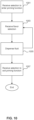
- FIG. 9A illustrates an example method for dispensing an available fluid in a "crew serve" mode according to an aspect of the disclosure.
- a selection of a beverage size may be received via input from the user using one of size buttons 134a-134c.
- the selected size remains active until another size is selected, for example, at step 903 .
- the corresponding flavor selection indicator can illuminate.
- a selection of a flavor or type or brand of beverage may be received via input from the user using one of flavor buttons 132a-132f.
- a user may select one of flavor buttons 132a-132f that corresponds to cherry flavoring, vanilla flavoring, strawberry flavoring, lemon flavoring, lime flavoring, peach flavoring, Sierra Mist ® branded beverage, Tropicana ® branded beverage, Diet Pepsi-Cola ® branded beverage, Pepsi-Cola ® branded beverage, Lipton Brisk ® Iced Tea branded beverage, Mountain Dew ® branded beverage, Diet Mountain Dew ® branded beverage, or MUG Root Beer ® branded beverage.
- the example method of FIG. 9A shows a particular order of steps, the exact order of the above steps could change, and the dispenser could receive additional input from the user before, after, and in between particular steps of the above example method.
- the order of the steps and/or what input is received during the course of a user's interaction with a dispenser may be dependent on the organization of the user interface.
- a selection of a flavor or type or brand of beverage may be received via input from the user via one of flavor buttons 132a-132f.
- a user may select one of flavor buttons 132a-132f that corresponds to cherry flavoring, vanilla flavoring, strawberry flavoring, lemon flavoring, lime flavoring, peach flavoring, Sierra Mist ® branded beverage, Tropicana ® branded beverage, Diet Pepsi-Cola ® branded beverage, Pepsi-Cola ® branded beverage, Lipton Brisk ® Iced Tea branded beverage, Mountain Dew ® branded beverage, Diet Mountain Dew ® branded beverage, or MUG Root Beer ® branded beverage.
- a selection of a beverage size may be received via input from the user using one of size buttons 134a-134c.
- control interface 130 can send electronic signals to pumps 70 to cause nozzle module 100 to dispense from nozzle 140 the flavor or beverage selected at step 905 in the appropriate size selected at step 903 .
- step 915 can initiate upon receipt of the beverage size selection in step 913 .
- the example method of FIG. 9B shows a particular order of steps, the exact order of the above steps could change, and the dispenser could receive additional input from the user before, after, and in between particular steps of the above example method.
- the order of the steps and/or what input is received during the course of a user's interaction with a dispenser may be dependent on the organization of the user interface.
- Priming of the pumps to push fluid through line 72 can be required when changing a product or to clear a sold out condition when one or more of concentrate sources 80 are empty. When changing products, priming avoids flavor cross-contamination from previous syrup flavors run through the line.
- FIG. 10 illustrates an example method for priming the fluid line.
- a selection to enter the priming function may be received via input from the user.
- the input to enter the priming function may be a combination of two or more of buttons 132a-132f and/or 134a-134c.
- a selection to enter the priming function may be received by the user simultaneously pressing size buttons 134a and 134c.
- a selection of a product e.g. , flavor or type or brand of beverage to prime may be received via input from the user using one of flavor buttons 132a-132f.
- the selected fluid may be dispensed to prime the line.
- the selected flavor or type or brand of beverage may pump for a predetermined period of time to clear the fluid line of any previous product and/or air and fill the fluid line with the desired product.
- the selected flavor or type or brand of beverage may pump as long as the use continues to press the selected flavor button. In this aspect, the user should continue to press the selected flavor button until a steady stream of product flows from the line.
- Steps 1003 and 1005 can be repeated for each product that needs to be primed.
- a selection to exit the priming function may be received via input from the user.
- the input to exit the priming function may be a combination of two or more of buttons 132a-132f and/or 134a-134c.
- a selection to exit the priming function may be received by the user simultaneously pressing size buttons 134a and 134c.
- the example method of FIG. 10 shows a particular order of steps, the exact order of the above steps could change, and the dispenser could receive additional input from the user before, after, and in between particular steps of the above example method.
- the order of the steps and/or what input is received during the course of a user's interaction with a dispenser may be dependent on the organization of the user interface.
- FIG. 11 illustrates an example computing device on which at least some of the various elements described herein can be implemented, including, but not limited to, various components of dispenser systems (e.g., beverage dispensing system 10 and/or nozzle module 100).
- Computing device 1100 may include one or more processors 1101, which may execute instructions of a computer program to perform, or cause to perform, any of the steps or functions described herein.
- the instructions may be stored in any type of computer-readable medium or memory, to configure the operation of the processor 1101.
- instructions may be stored in a read-only memory (ROM) 1102, random access memory (RAM) 1103, removable media 1104, such as a Universal Serial Bus (USB) drive, compact disk (CD) or digital versatile disk (DVD), floppy disk drive, flash card, or any other desired electronic storage medium. Instructions may also be stored in an attached (or internal) hard drive 1105.
- ROM read-only memory
- RAM random access memory
- removable media 1104 such as a Universal Serial Bus (USB) drive, compact disk (CD) or digital versatile disk (DVD), floppy disk drive, flash card, or any other desired electronic storage medium.
- USB Universal Serial Bus
- CD compact disk
- DVD digital versatile disk
- floppy disk drive floppy disk drive
- flash card or any other desired electronic storage medium.
- Control interface 130 and/or pumps 70 can be controlled by computing device 1100 that includes processors 1101.
- Computing device 1100 and processors 1101 receive electronic signals from control interface 130 and send electronic signals to initiate pumps 70.
- Computing device 1100 and processors 1101 can provide intelligent control of the beverage dispensing system 10.
- Computing device 1100 and processors 1101 can also monitor system status such as the fluid temperatures, number of drinks dispensed, a sold out condition for one or more of diluent sources 80, and sensors that determine the amount of concentrate remaining in the beverage dispensing system. Computing device 1100 and processors 1101 can also provide service diagnostics, and the ability to remotely poll the electronic status.
- Computing device 1100 may include one or more output devices, such as a display 1106, and may include one or more output device controllers 1107, such as a video processor. There may also be one or more user input devices 1008, such as a touch screen, remote control, keyboard, mouse, microphone, card reader, RFID reader, etc.
- the computing device 1100 may also include one or more network interfaces, such as input/output circuits 1109 to communicate with an external network 1110.
- the network interface may be a wired interface, wireless interface, or a combination of the two.
- the interface 1109 may include a modem (e.g., a cable modem), and network 1110 may include the communication lines of the networks illustrated in FIG. 10 , or any other desired network.
- FIG. 11 example is an illustrative hardware configuration. Modifications may be made to add, remove, combine, divide, etc. components as desired. Additionally, the components illustrated may be implemented using basic computing devices and components, and the same components (e.g., processor 1101, storage 1102, user input device 1108, etc.) may be used to implement any of the other computing devices and components described herein.
- processor 1101, storage 1102, user input device 1108, etc. may be used to implement any of the other computing devices and components described herein.
- One or more aspects of the disclosure may be embodied in a computer-usable data and/or computer-executable instructions, such as in one or more program modules, executed by one or more computers or other devices.
- program modules include routines, programs, objects, components, data structures, etc. that perform particular tasks or implement particular abstract data types when executed by a processor in a computer or other data processing device.
- the computer executable instructions may be stored on one or more computer readable media such as a hard disk, optical disk, removable storage media, solid state memory, RAM, etc.
- the functionality of the program modules may be combined or distributed as desired in various embodiments.
- firmware or hardware equivalents such as integrated circuits, field programmable gate arrays (FPGA), controllers, application-specific integrated circuits (ASICS), combinations of hardware/firmware/software, and the like.
- FPGA field programmable gate arrays
- ASICS application-specific integrated circuits
- Particular data structures may be used to more effectively implement one or more aspects of the disclosure, and such data structures are contemplated within the scope of computer executable instructions and computer-usable data described herein.
Landscapes
- Engineering & Computer Science (AREA)
- Mechanical Engineering (AREA)
- Devices For Dispensing Beverages (AREA)
Claims (14)
- Getränkeabgabesystem, umfassend:einen Getränkespender (10), der ein Getränkespendergehäuse (13) umfasst; undein Düsenmodul (100), umfassend:ein Düsenmodulgehäuse (104), das ein erstes Ende (106) zum Anbringen an dem Getränkespendergehäuse (13) aufweist; undeine Düse (140) neben einem zweiten Ende (114) des Düsenmodulgehäuses (104) dergestalt, dass die Düse (140) entlang einer zweiten Achse (204) ausgerichtet und dazu eingerichtet ist, um eine zweite horizontale Distanz (D2) von dem Getränkespendergehäuse (13) beabstandet zu sein,wobei der Getränkespender (10) eine Getränkespenderdüse (26) aufweist, die entlang einer ersten Achse (202) ausgerichtet und um eine erste horizontale Distanz (D1) von dem Getränkespendergehäuse (13) beabstandet ist, undwobei die erste Achse (202) und die zweite Achse (204) parallel zu einer Basis (11) des Getränkespendergehäuses (13) verlaufen, wobei die erste Achse (202) um die erste horizontale Distanz (D1) von dem Getränkespendergehäuse (10) beabstandet ist und die zweite Achse (204) um die zweite horizontale Distanz (D2) von dem Getränkespendergehäuse (10) beabstandet ist, wobei die zweite horizontale Distanz (D2) größer als die erste horizontale Distanz (D1) ist.
- Getränkeabgabesystem nach Anspruch 1, wobeidas Getränkespendergehäuse (13) eine Ventilhaltegehäusefläche (18) aufweist;wobei der Getränkespender (10) des Weiteren ein Getränkeabgabeventil (20) umfasst, das sich von dem Getränkespendergehäuse (13) erstreckt, wobei das Getränkeabgabeventil (20) die Spenderdüse (26) und ein Ventilgehäuse (22) zum Anbringen an der Ventilhaltegehäusefläche (18) aufweist, wobei das Getränkeabgabeventil (20) an der Ventilhaltegehäusefläche (18) so gestützt ist, dass die Spenderdüse (26) allgemein entlang einer ersten Achse (202) ausgerichtet ist; undwobei das Düsenmodul (100) aufweist:das Düsenmodulgehäuse (104), dessen erstes Ende (106) an ein oberes Ende (10b) des Getränkespendergehäuses (13) stößt und dessen zweites Ende (114) sich von dem ersten Ende (106) erstreckt; unddie Düse (140), die eine Düsenmoduldüse (140) neben dem zweiten Ende (114) ist, dergestalt, dass die Düsenmoduldüse (140) entlang einer zweiten Achse (204) ausgerichtet ist, die parallel zu, und in einem Abstand von, der ersten Achse (202) in einer horizontalen Richtung verläuft,wobei die erste Achse (202) um eine erste vertikale Distanz von der Basis (11) beabstandet ist und die zweite Achse (204) um eine zweite vertikale Distanz von der Basis (11) beabstandet ist, wobei die zweite vertikale Distanz größer als die erste vertikale Distanz ist, undwobei die erste Achse (202) um die erste horizontale Distanz (D1) von der Ventilhaltegehäusefläche (18) beabstandet ist und die zweite Achse (204) um die zweite horizontale Distanz (D2) von der Ventilhaltegehäusefläche (18) beabstandet ist.
- Getränkeabgabesystem nach Anspruch 2, wobei die zweite Achse (204) von der ersten Achse (202) um eine vertikale Distanz (H) in einem Bereich von 2,5 cm (ein Inch) bis 40 cm (15 Inch) beabstandet ist.
- Getränkeabgabesystem nach Anspruch 2, des Weiteren umfassend:ein zweites Getränkeabgabeventil (20), das sich von dem Getränkespendergehäuse (13) erstreckt, wobei das zweite Getränkeabgabeventil (20) eine zweite Spenderdüse (26) undein zweites Ventilgehäuse (22) zum Anbringen an der Ventilhaltegehäusefläche (18) aufweist, wobei das zweite Getränkeabgabeventil (20) an der Ventilhaltegehäusefläche (18) so gestützt ist, dass die zweite Spenderdüse (26) allgemein entlang einer ersten Achse (202) ausgerichtet ist.
- Getränkeabgabesystem nach Anspruch 2, wobei das Düsenmodulgehäuse (104) mit dem Getränkespendergehäuse (13) gekoppelt ist.
- Getränkeabgabesystem nach Anspruch 2, wobei das Düsenmodul (100) eine zuvor abgemessene Fluidmenge auf der Grundlage einer ersten Benutzereingabe und einer zweiten Benutzereingabe abgibt.
- Getränkeabgabesystem nach Anspruch 2, wobei die Basis (11) an einem unteren Ende (10a) des Getränkespendergehäuses (13) angebracht ist, wobei die Basis (11) einen Abfallauffangabschnitt aufweist, der einen Behältnisbereich aufweist,wobei die Spenderdüse (26) oberhalb des Behältnisbereichs positioniert ist, um ein erstes Fluid in den Behältnisbereich hinein abzugeben, undwobei die Düsenmoduldüse (140) oberhalb des Behältnisbereichs angeordnet ist, um ein zweites Fluid in den Behältnisbereich hinein abzugeben.
- Getränkeabgabesystem nach Anspruch 7, wobei das erste Fluid eine Zusatzzutat ist und das zweite Fluid ein Markengetränk ist.
- Getränkeabgabesystem nach Anspruch 7, wobei das Düsenmodul (100) des Weiteren umfasst:eine Steuerschnittstelle (130) zum Regulieren der Zufuhr des zweiten Fluids, wobei die Steuerschnittstelle (130) einen Schalter aufweist; undein elektronisches Steuersystem, das mit dem Schalter gekoppelt und dazu eingerichtet ist, elektronische Steuersignale von der Steuerschnittstelle (130) zum Regulieren der Zufuhr des zweiten Fluids zu empfangen.
- Getränkeabgabesystem nach Anspruch 1, wobei die zweite horizontale Distanz (D2) in einem Bereich von 2,5 cm (ein Inch) bis 25 cm (10 Inch) liegt.
- Getränkeabgabesystem nach Anspruch 1, wobei die Düse (140) dazu eingerichtet ist, um eine vertikale Distanz (H) von der Getränkespenderdüse (26) beabstandet zu sein.
- Getränkeabgabesystem nach Anspruch 11, wobei die vertikale Distanz (H) in einem Bereich von 2,5 cm (ein Inch) bis 40 cm (15 Inch) liegt.
- Getränkeabgabesystem nach Anspruch 1, wobei das Düsenmodul (100) dazu eingerichtet ist, eine zuvor abgemessene Fluidmenge auf der Grundlage einer ersten Benutzereingabe abzugeben.
- Getränkeabgabesystem nach Anspruch 1, wobei das Düsenmodul (100) des Weiteren umfasst:eine Steuerschnittstelle (130) zum Regulieren der Zufuhr des Düsenmodulfluids, wobei die Steuerschnittstelle (130) einen Schalter aufweist; undein elektronisches Steuersystem, das mit dem Schalter gekoppelt und dazu eingerichtet ist, elektronische Steuersignale von der Steuerschnittstelle (130) zum Regulieren der Zufuhr des Düsenmodulfluids zu empfangen.
Applications Claiming Priority (2)
| Application Number | Priority Date | Filing Date | Title |
|---|---|---|---|
| US15/637,681 US10399837B2 (en) | 2017-06-29 | 2017-06-29 | Beverage dispensing system |
| PCT/US2018/038026 WO2019005520A1 (en) | 2017-06-29 | 2018-06-18 | BEVERAGE DISTRIBUTION SYSTEM |
Publications (3)
| Publication Number | Publication Date |
|---|---|
| EP3645451A1 EP3645451A1 (de) | 2020-05-06 |
| EP3645451A4 EP3645451A4 (de) | 2021-03-24 |
| EP3645451B1 true EP3645451B1 (de) | 2025-03-05 |
Family
ID=64735289
Family Applications (1)
| Application Number | Title | Priority Date | Filing Date |
|---|---|---|---|
| EP18822613.8A Active EP3645451B1 (de) | 2017-06-29 | 2018-06-18 | Getränkeausgabesystem |
Country Status (8)
| Country | Link |
|---|---|
| US (3) | US10399837B2 (de) |
| EP (1) | EP3645451B1 (de) |
| JP (1) | JP7160851B2 (de) |
| CN (1) | CN110831889B (de) |
| AU (1) | AU2018291997B2 (de) |
| CA (1) | CA3067823A1 (de) |
| MX (2) | MX2020000220A (de) |
| WO (1) | WO2019005520A1 (de) |
Families Citing this family (12)
| Publication number | Priority date | Publication date | Assignee | Title |
|---|---|---|---|---|
| US10399837B2 (en) * | 2017-06-29 | 2019-09-03 | Pepsico, Inc. | Beverage dispensing system |
| JP6467615B1 (ja) * | 2017-08-07 | 2019-02-13 | 株式会社Tree Field | 飲料製造装置及び制御方法 |
| US11926516B2 (en) | 2019-02-06 | 2024-03-12 | The Coca-Cola Company | Beverage dispensing systems with limited time offering circuits |
| GB2582949A (en) * | 2019-04-10 | 2020-10-14 | Marco Beverage Systems Ltd | A beverage dispense system |
| CN110668384A (zh) * | 2019-11-04 | 2020-01-10 | 比率机器人科技(北京)有限公司 | 一种用于自动餐饮设备的物料塔及其物料运输方法 |
| EP4263418A4 (de) * | 2020-12-19 | 2024-10-23 | Pepsico Inc | Berührungslose fusspaddelbetriebene spender |
| US11666163B2 (en) * | 2021-01-19 | 2023-06-06 | Sanispenser, Inc. | Contactless condiment dispenser |
| US11608260B2 (en) * | 2021-03-17 | 2023-03-21 | Global Industrial Distribution Inc. | Water cooler pan of bottle filler fountain |
| USD992328S1 (en) | 2021-07-27 | 2023-07-18 | Pepsico, Inc. | Dispenser |
| EP4151587B1 (de) * | 2021-09-16 | 2025-11-26 | Unito Smart Technologies Limited | Getränkemischvorrichtung und mischbatteriesystem |
| USD996114S1 (en) | 2021-09-17 | 2023-08-22 | Pepsico, Inc. | Dispenser |
| US12053117B1 (en) * | 2023-05-05 | 2024-08-06 | Starbucks Corporation | Systems, methods, and devices, for parallel extraction of beverages |
Citations (5)
| Publication number | Priority date | Publication date | Assignee | Title |
|---|---|---|---|---|
| US6286721B1 (en) * | 1997-12-18 | 2001-09-11 | Enrica Pellegrini | Modular manifold system for post-mix and pre-mix beverages dispensers |
| WO2006131431A1 (en) * | 2005-06-08 | 2006-12-14 | Massimo Baldin | Automatic cocktail-bar |
| US9085451B2 (en) * | 2012-08-01 | 2015-07-21 | Schroeder Industries, Inc. | Multi-flavor mechanical dispensing valve for a single flavor multi-head beverage dispenser |
| US20200270116A1 (en) * | 2019-02-22 | 2020-08-27 | Lg Electronics Inc. | Liquid dispensing device |
| KR20200134193A (ko) * | 2019-02-22 | 2020-12-01 | 엘지전자 주식회사 | 워터 디스펜싱 장치 |
Family Cites Families (26)
| Publication number | Priority date | Publication date | Assignee | Title |
|---|---|---|---|---|
| US1713795A (en) * | 1925-09-08 | 1929-05-21 | Weber Showcase & Fixture Compa | Soda fountain |
| FR840904A (fr) | 1938-06-02 | 1939-05-08 | Fond Nestor Martin | Casier à bouteilles formant chantier de soutirage pour celles-ci |
| US3580425A (en) * | 1968-09-26 | 1971-05-25 | Electronic Dispensers Internat | Beverage dispenser |
| US3915207A (en) * | 1974-04-16 | 1975-10-28 | Food Systems Inc Entire | High-speed, automatic, powdered food and heated water dispenser |
| US4008832A (en) | 1975-10-28 | 1977-02-22 | The Coca-Cola Co. | Three drink gravity dispenser for cool beverages |
| USRE33943E (en) * | 1984-09-21 | 1992-06-02 | Jet Spray Corp. | Post mix fruit juice dispenser |
| USD324464S (en) * | 1989-06-19 | 1992-03-10 | The Coca-Cola Company | Beverage dispensing machine |
| US5305927A (en) * | 1993-01-29 | 1994-04-26 | Mattel, Inc. | Hand-pumped toy beverage dispenser |
| US6634159B1 (en) | 1999-09-20 | 2003-10-21 | Sanyo Electric Co., Ltd. | Taping apparatus for electronic components |
| US6328181B1 (en) * | 2000-02-02 | 2001-12-11 | Lancer Partnership, Ltd. | Enhanced flow controller for a beverage dispenser |
| US6234354B1 (en) * | 2000-05-01 | 2001-05-22 | The Coca-Cola Company | Soft drink dispensing machine with modular customer interface unit |
| US6364159B1 (en) * | 2000-05-01 | 2002-04-02 | The Coca Cola Company | Self-monitoring, intelligent fountain dispenser |
| WO2003026966A1 (en) * | 2001-09-28 | 2003-04-03 | Manitowoc Foodservice Companies, Inc. | Beverage dispenser and automatic shut-off valve |
| CA2463314A1 (en) * | 2001-10-19 | 2003-05-01 | Manitowoc Foodservice Companies, Inc. | Beverage dispenser with integral ice maker |
| EP1545993A4 (de) * | 2002-10-04 | 2011-01-05 | Lancer Partnership Ltd | Abgabevorrichtung für eisgekühlte getränke zahlreicher hersteller |
| US7624895B2 (en) * | 2005-02-17 | 2009-12-01 | Lancer Partnership, Ltd. | Tower dispenser |
| US7641074B2 (en) * | 2005-09-15 | 2010-01-05 | Lancer Partnership, Ltd. | Multiple flow circuits for a product dispenser |
| CN101300190B (zh) * | 2005-11-04 | 2013-02-20 | 可口可乐公司 | 分配调味剂和混合饮料的系统和方法 |
| US8074842B2 (en) * | 2007-05-08 | 2011-12-13 | Lancer Partnership, Ltd. | Method and apparatus for a modular dispensing tower |
| US9622615B2 (en) | 2008-11-10 | 2017-04-18 | Automatic Bar Controls, Inc. | Touch screen interface for a beverage dispensing machine |
| US9652756B2 (en) * | 2009-07-23 | 2017-05-16 | Smart Bar Usa Llc | Point of sale interface for an automatic beverage dispenser |
| US8746506B2 (en) | 2011-05-26 | 2014-06-10 | Pepsico, Inc. | Multi-tower modular dispensing system |
| CH706586B1 (de) * | 2012-06-04 | 2016-04-15 | Schaerer Ag | Ausgabeeinheit für einen Getränkeautomaten, Getränkeautomat mit einer solchen Ausgabeeinheit sowie Verfahren zum Betrieb eines solchen Getränkeautomaten. |
| US9643828B2 (en) * | 2013-04-08 | 2017-05-09 | Manitowoc Foodservice Companies, Llc | Arcuate multi-dispensing beverage dispenser |
| US9346659B2 (en) * | 2013-05-20 | 2016-05-24 | Manitowoc Foodservice Companies, Llc | Hybrid beverage dispenser |
| US10399837B2 (en) * | 2017-06-29 | 2019-09-03 | Pepsico, Inc. | Beverage dispensing system |
-
2017
- 2017-06-29 US US15/637,681 patent/US10399837B2/en active Active
-
2018
- 2018-06-18 MX MX2020000220A patent/MX2020000220A/es unknown
- 2018-06-18 CA CA3067823A patent/CA3067823A1/en active Pending
- 2018-06-18 AU AU2018291997A patent/AU2018291997B2/en active Active
- 2018-06-18 JP JP2019572466A patent/JP7160851B2/ja active Active
- 2018-06-18 EP EP18822613.8A patent/EP3645451B1/de active Active
- 2018-06-18 WO PCT/US2018/038026 patent/WO2019005520A1/en not_active Ceased
- 2018-06-18 CN CN201880043301.9A patent/CN110831889B/zh active Active
-
2019
- 2019-07-26 US US16/523,570 patent/US10787356B2/en active Active
-
2020
- 2020-01-08 MX MX2023011041A patent/MX2023011041A/es unknown
- 2020-09-28 US US17/035,155 patent/US11214472B2/en active Active
Patent Citations (5)
| Publication number | Priority date | Publication date | Assignee | Title |
|---|---|---|---|---|
| US6286721B1 (en) * | 1997-12-18 | 2001-09-11 | Enrica Pellegrini | Modular manifold system for post-mix and pre-mix beverages dispensers |
| WO2006131431A1 (en) * | 2005-06-08 | 2006-12-14 | Massimo Baldin | Automatic cocktail-bar |
| US9085451B2 (en) * | 2012-08-01 | 2015-07-21 | Schroeder Industries, Inc. | Multi-flavor mechanical dispensing valve for a single flavor multi-head beverage dispenser |
| US20200270116A1 (en) * | 2019-02-22 | 2020-08-27 | Lg Electronics Inc. | Liquid dispensing device |
| KR20200134193A (ko) * | 2019-02-22 | 2020-12-01 | 엘지전자 주식회사 | 워터 디스펜싱 장치 |
Also Published As
| Publication number | Publication date |
|---|---|
| AU2018291997A1 (en) | 2020-01-16 |
| JP7160851B2 (ja) | 2022-10-25 |
| CN110831889A (zh) | 2020-02-21 |
| EP3645451A4 (de) | 2021-03-24 |
| RU2020102352A3 (de) | 2021-10-25 |
| JP2020525367A (ja) | 2020-08-27 |
| CN110831889B (zh) | 2022-10-14 |
| AU2018291997B2 (en) | 2022-06-30 |
| US11214472B2 (en) | 2022-01-04 |
| RU2020102352A (ru) | 2021-07-29 |
| US20190002264A1 (en) | 2019-01-03 |
| US20210024340A1 (en) | 2021-01-28 |
| EP3645451A1 (de) | 2020-05-06 |
| CA3067823A1 (en) | 2019-01-03 |
| MX2020000220A (es) | 2020-08-06 |
| MX2023011041A (es) | 2023-09-27 |
| US10399837B2 (en) | 2019-09-03 |
| US10787356B2 (en) | 2020-09-29 |
| US20190345016A1 (en) | 2019-11-14 |
| WO2019005520A1 (en) | 2019-01-03 |
Similar Documents
| Publication | Publication Date | Title |
|---|---|---|
| EP3645451B1 (de) | Getränkeausgabesystem | |
| EP3558072B1 (de) | Getränkespendersystem und -verfahren | |
| US8676376B2 (en) | Systems and methods for dispensing control for a product dispenser | |
| US9643828B2 (en) | Arcuate multi-dispensing beverage dispenser | |
| CN106241712B (zh) | 用于提供混合饮料分配器中的份量控制编程的系统和方法 | |
| US11928911B2 (en) | Systems and methods for dispensing products selected at remote point-of-sale devices | |
| US20150069087A1 (en) | Hybrid beverage dispenser | |
| EP3619158A1 (de) | Selbstbedienungsgetränkespender | |
| US20120325845A1 (en) | Systems and Methods for Recipe Portion Control for a Product Dispenser | |
| US20150344284A1 (en) | Automatic fluid dispenser | |
| EP3328787B1 (de) | Modulares system zur ausgabe von zusätzlichen zutaten | |
| EP4237368A2 (de) | Getränkeausgabevorrichtung | |
| RU2772182C2 (ru) | Система выдачи напитка |
Legal Events
| Date | Code | Title | Description |
|---|---|---|---|
| STAA | Information on the status of an ep patent application or granted ep patent |
Free format text: STATUS: THE INTERNATIONAL PUBLICATION HAS BEEN MADE |
|
| PUAI | Public reference made under article 153(3) epc to a published international application that has entered the european phase |
Free format text: ORIGINAL CODE: 0009012 |
|
| STAA | Information on the status of an ep patent application or granted ep patent |
Free format text: STATUS: REQUEST FOR EXAMINATION WAS MADE |
|
| 17P | Request for examination filed |
Effective date: 20200109 |
|
| AK | Designated contracting states |
Kind code of ref document: A1 Designated state(s): AL AT BE BG CH CY CZ DE DK EE ES FI FR GB GR HR HU IE IS IT LI LT LU LV MC MK MT NL NO PL PT RO RS SE SI SK SM TR |
|
| AX | Request for extension of the european patent |
Extension state: BA ME |
|
| RIN1 | Information on inventor provided before grant (corrected) |
Inventor name: MADDEN, JOSEPH Inventor name: JERSEY, STEVEN T. Inventor name: UBIDIA, FERNANDO Inventor name: LOOMIS, SCOTT |
|
| DAV | Request for validation of the european patent (deleted) | ||
| DAX | Request for extension of the european patent (deleted) | ||
| A4 | Supplementary search report drawn up and despatched |
Effective date: 20210223 |
|
| RIC1 | Information provided on ipc code assigned before grant |
Ipc: B67D 1/00 20060101ALI20210217BHEP Ipc: B67D 1/06 20060101AFI20210217BHEP |
|
| STAA | Information on the status of an ep patent application or granted ep patent |
Free format text: STATUS: EXAMINATION IS IN PROGRESS |
|
| 17Q | First examination report despatched |
Effective date: 20240219 |
|
| GRAP | Despatch of communication of intention to grant a patent |
Free format text: ORIGINAL CODE: EPIDOSNIGR1 |
|
| STAA | Information on the status of an ep patent application or granted ep patent |
Free format text: STATUS: GRANT OF PATENT IS INTENDED |
|
| RIC1 | Information provided on ipc code assigned before grant |
Ipc: B67D 1/00 20060101ALI20240909BHEP Ipc: B67D 1/08 20060101ALI20240909BHEP Ipc: B67D 1/06 20060101AFI20240909BHEP |
|
| INTG | Intention to grant announced |
Effective date: 20240927 |
|
| GRAS | Grant fee paid |
Free format text: ORIGINAL CODE: EPIDOSNIGR3 |
|
| GRAA | (expected) grant |
Free format text: ORIGINAL CODE: 0009210 |
|
| STAA | Information on the status of an ep patent application or granted ep patent |
Free format text: STATUS: THE PATENT HAS BEEN GRANTED |
|
| AK | Designated contracting states |
Kind code of ref document: B1 Designated state(s): AL AT BE BG CH CY CZ DE DK EE ES FI FR GB GR HR HU IE IS IT LI LT LU LV MC MK MT NL NO PL PT RO RS SE SI SK SM TR |
|
| P01 | Opt-out of the competence of the unified patent court (upc) registered |
Free format text: CASE NUMBER: APP_3801/2025 Effective date: 20250123 |
|
| RAP3 | Party data changed (applicant data changed or rights of an application transferred) |
Owner name: PEPSICO, INC. |
|
| REG | Reference to a national code |
Ref country code: GB Ref legal event code: FG4D |
|
| REG | Reference to a national code |
Ref country code: CH Ref legal event code: EP |
|
| REG | Reference to a national code |
Ref country code: DE Ref legal event code: R096 Ref document number: 602018079874 Country of ref document: DE |
|
| REG | Reference to a national code |
Ref country code: IE Ref legal event code: FG4D |
|
| PG25 | Lapsed in a contracting state [announced via postgrant information from national office to epo] |
Ref country code: RS Free format text: LAPSE BECAUSE OF FAILURE TO SUBMIT A TRANSLATION OF THE DESCRIPTION OR TO PAY THE FEE WITHIN THE PRESCRIBED TIME-LIMIT Effective date: 20250605 |
|
| PG25 | Lapsed in a contracting state [announced via postgrant information from national office to epo] |
Ref country code: FI Free format text: LAPSE BECAUSE OF FAILURE TO SUBMIT A TRANSLATION OF THE DESCRIPTION OR TO PAY THE FEE WITHIN THE PRESCRIBED TIME-LIMIT Effective date: 20250305 |
|
| REG | Reference to a national code |
Ref country code: NL Ref legal event code: MP Effective date: 20250305 |
|
| PG25 | Lapsed in a contracting state [announced via postgrant information from national office to epo] |
Ref country code: ES Free format text: LAPSE BECAUSE OF FAILURE TO SUBMIT A TRANSLATION OF THE DESCRIPTION OR TO PAY THE FEE WITHIN THE PRESCRIBED TIME-LIMIT Effective date: 20250305 |
|
| REG | Reference to a national code |
Ref country code: LT Ref legal event code: MG9D |
|
| PG25 | Lapsed in a contracting state [announced via postgrant information from national office to epo] |
Ref country code: NO Free format text: LAPSE BECAUSE OF FAILURE TO SUBMIT A TRANSLATION OF THE DESCRIPTION OR TO PAY THE FEE WITHIN THE PRESCRIBED TIME-LIMIT Effective date: 20250605 |
|
| PG25 | Lapsed in a contracting state [announced via postgrant information from national office to epo] |
Ref country code: HR Free format text: LAPSE BECAUSE OF FAILURE TO SUBMIT A TRANSLATION OF THE DESCRIPTION OR TO PAY THE FEE WITHIN THE PRESCRIBED TIME-LIMIT Effective date: 20250305 |
|
| PG25 | Lapsed in a contracting state [announced via postgrant information from national office to epo] |
Ref country code: LV Free format text: LAPSE BECAUSE OF FAILURE TO SUBMIT A TRANSLATION OF THE DESCRIPTION OR TO PAY THE FEE WITHIN THE PRESCRIBED TIME-LIMIT Effective date: 20250305 |
|
| PG25 | Lapsed in a contracting state [announced via postgrant information from national office to epo] |
Ref country code: BG Free format text: LAPSE BECAUSE OF FAILURE TO SUBMIT A TRANSLATION OF THE DESCRIPTION OR TO PAY THE FEE WITHIN THE PRESCRIBED TIME-LIMIT Effective date: 20250305 Ref country code: GR Free format text: LAPSE BECAUSE OF FAILURE TO SUBMIT A TRANSLATION OF THE DESCRIPTION OR TO PAY THE FEE WITHIN THE PRESCRIBED TIME-LIMIT Effective date: 20250606 |
|
| REG | Reference to a national code |
Ref country code: AT Ref legal event code: MK05 Ref document number: 1772831 Country of ref document: AT Kind code of ref document: T Effective date: 20250305 |
|
| PG25 | Lapsed in a contracting state [announced via postgrant information from national office to epo] |
Ref country code: NL Free format text: LAPSE BECAUSE OF FAILURE TO SUBMIT A TRANSLATION OF THE DESCRIPTION OR TO PAY THE FEE WITHIN THE PRESCRIBED TIME-LIMIT Effective date: 20250305 |
|
| PG25 | Lapsed in a contracting state [announced via postgrant information from national office to epo] |
Ref country code: SE Free format text: LAPSE BECAUSE OF FAILURE TO SUBMIT A TRANSLATION OF THE DESCRIPTION OR TO PAY THE FEE WITHIN THE PRESCRIBED TIME-LIMIT Effective date: 20250305 |
|
| PG25 | Lapsed in a contracting state [announced via postgrant information from national office to epo] |
Ref country code: SM Free format text: LAPSE BECAUSE OF FAILURE TO SUBMIT A TRANSLATION OF THE DESCRIPTION OR TO PAY THE FEE WITHIN THE PRESCRIBED TIME-LIMIT Effective date: 20250305 |
|
| PG25 | Lapsed in a contracting state [announced via postgrant information from national office to epo] |
Ref country code: PT Free format text: LAPSE BECAUSE OF FAILURE TO SUBMIT A TRANSLATION OF THE DESCRIPTION OR TO PAY THE FEE WITHIN THE PRESCRIBED TIME-LIMIT Effective date: 20250707 |
|
| PG25 | Lapsed in a contracting state [announced via postgrant information from national office to epo] |
Ref country code: PL Free format text: LAPSE BECAUSE OF FAILURE TO SUBMIT A TRANSLATION OF THE DESCRIPTION OR TO PAY THE FEE WITHIN THE PRESCRIBED TIME-LIMIT Effective date: 20250305 Ref country code: IT Free format text: LAPSE BECAUSE OF FAILURE TO SUBMIT A TRANSLATION OF THE DESCRIPTION OR TO PAY THE FEE WITHIN THE PRESCRIBED TIME-LIMIT Effective date: 20250305 |
|
| PG25 | Lapsed in a contracting state [announced via postgrant information from national office to epo] |
Ref country code: AT Free format text: LAPSE BECAUSE OF FAILURE TO SUBMIT A TRANSLATION OF THE DESCRIPTION OR TO PAY THE FEE WITHIN THE PRESCRIBED TIME-LIMIT Effective date: 20250305 |
|
| PG25 | Lapsed in a contracting state [announced via postgrant information from national office to epo] |
Ref country code: EE Free format text: LAPSE BECAUSE OF FAILURE TO SUBMIT A TRANSLATION OF THE DESCRIPTION OR TO PAY THE FEE WITHIN THE PRESCRIBED TIME-LIMIT Effective date: 20250305 Ref country code: CZ Free format text: LAPSE BECAUSE OF FAILURE TO SUBMIT A TRANSLATION OF THE DESCRIPTION OR TO PAY THE FEE WITHIN THE PRESCRIBED TIME-LIMIT Effective date: 20250305 |
|
| PG25 | Lapsed in a contracting state [announced via postgrant information from national office to epo] |
Ref country code: RO Free format text: LAPSE BECAUSE OF FAILURE TO SUBMIT A TRANSLATION OF THE DESCRIPTION OR TO PAY THE FEE WITHIN THE PRESCRIBED TIME-LIMIT Effective date: 20250305 |
|
| PG25 | Lapsed in a contracting state [announced via postgrant information from national office to epo] |
Ref country code: SK Free format text: LAPSE BECAUSE OF FAILURE TO SUBMIT A TRANSLATION OF THE DESCRIPTION OR TO PAY THE FEE WITHIN THE PRESCRIBED TIME-LIMIT Effective date: 20250305 |
|
| PG25 | Lapsed in a contracting state [announced via postgrant information from national office to epo] |
Ref country code: IS Free format text: LAPSE BECAUSE OF FAILURE TO SUBMIT A TRANSLATION OF THE DESCRIPTION OR TO PAY THE FEE WITHIN THE PRESCRIBED TIME-LIMIT Effective date: 20250705 |
|
| REG | Reference to a national code |
Ref country code: DE Ref legal event code: R097 Ref document number: 602018079874 Country of ref document: DE |
|
| PLBE | No opposition filed within time limit |
Free format text: ORIGINAL CODE: 0009261 |
|
| STAA | Information on the status of an ep patent application or granted ep patent |
Free format text: STATUS: NO OPPOSITION FILED WITHIN TIME LIMIT |
|
| PG25 | Lapsed in a contracting state [announced via postgrant information from national office to epo] |
Ref country code: DK Free format text: LAPSE BECAUSE OF FAILURE TO SUBMIT A TRANSLATION OF THE DESCRIPTION OR TO PAY THE FEE WITHIN THE PRESCRIBED TIME-LIMIT Effective date: 20250305 |
|
| REG | Reference to a national code |
Ref country code: CH Ref legal event code: L10 Free format text: ST27 STATUS EVENT CODE: U-0-0-L10-L00 (AS PROVIDED BY THE NATIONAL OFFICE) Effective date: 20260114 |
|
| REG | Reference to a national code |
Ref country code: CH Ref legal event code: H13 Free format text: ST27 STATUS EVENT CODE: U-0-0-H10-H13 (AS PROVIDED BY THE NATIONAL OFFICE) Effective date: 20260127 |
|
| PG25 | Lapsed in a contracting state [announced via postgrant information from national office to epo] |
Ref country code: MC Free format text: LAPSE BECAUSE OF FAILURE TO SUBMIT A TRANSLATION OF THE DESCRIPTION OR TO PAY THE FEE WITHIN THE PRESCRIBED TIME-LIMIT Effective date: 20250305 |
|
| 26N | No opposition filed |
Effective date: 20251208 |