EP3645248B1 - Automated calibrating of a device for fully parallel additive production of a component with combined work areas - Google Patents
Automated calibrating of a device for fully parallel additive production of a component with combined work areas Download PDFInfo
- Publication number
- EP3645248B1 EP3645248B1 EP18732117.9A EP18732117A EP3645248B1 EP 3645248 B1 EP3645248 B1 EP 3645248B1 EP 18732117 A EP18732117 A EP 18732117A EP 3645248 B1 EP3645248 B1 EP 3645248B1
- Authority
- EP
- European Patent Office
- Prior art keywords
- laser
- light
- devices
- reference marks
- work field
- Prior art date
- Legal status (The legal status is an assumption and is not a legal conclusion. Google has not performed a legal analysis and makes no representation as to the accuracy of the status listed.)
- Active
Links
- 238000004519 manufacturing process Methods 0.000 title claims description 47
- 239000000654 additive Substances 0.000 title claims description 32
- 230000000996 additive effect Effects 0.000 title claims description 32
- 238000001514 detection method Methods 0.000 claims description 54
- 230000003287 optical effect Effects 0.000 claims description 39
- 238000000034 method Methods 0.000 claims description 32
- 238000012545 processing Methods 0.000 claims description 32
- 239000000843 powder Substances 0.000 claims description 29
- 238000004590 computer program Methods 0.000 claims description 5
- 238000003860 storage Methods 0.000 claims description 3
- 238000012937 correction Methods 0.000 claims description 2
- 238000010276 construction Methods 0.000 description 122
- 239000003550 marker Substances 0.000 description 51
- 239000000463 material Substances 0.000 description 7
- 230000003993 interaction Effects 0.000 description 6
- 238000010330 laser marking Methods 0.000 description 6
- 230000008859 change Effects 0.000 description 5
- 230000000694 effects Effects 0.000 description 4
- 230000008569 process Effects 0.000 description 4
- 238000011161 development Methods 0.000 description 3
- 230000018109 developmental process Effects 0.000 description 3
- 238000009826 distribution Methods 0.000 description 3
- 239000007858 starting material Substances 0.000 description 3
- 230000008901 benefit Effects 0.000 description 2
- 238000005516 engineering process Methods 0.000 description 2
- 239000011521 glass Substances 0.000 description 2
- 239000000126 substance Substances 0.000 description 2
- 230000000007 visual effect Effects 0.000 description 2
- 238000004532 chromating Methods 0.000 description 1
- 230000003247 decreasing effect Effects 0.000 description 1
- 230000001419 dependent effect Effects 0.000 description 1
- 238000013461 design Methods 0.000 description 1
- 238000005553 drilling Methods 0.000 description 1
- 238000005530 etching Methods 0.000 description 1
- 230000006870 function Effects 0.000 description 1
- 230000006872 improvement Effects 0.000 description 1
- 238000009776 industrial production Methods 0.000 description 1
- 230000007246 mechanism Effects 0.000 description 1
- 238000002844 melting Methods 0.000 description 1
- 230000008018 melting Effects 0.000 description 1
- 238000003801 milling Methods 0.000 description 1
- 238000012544 monitoring process Methods 0.000 description 1
- 238000005457 optimization Methods 0.000 description 1
- 230000001360 synchronised effect Effects 0.000 description 1
- 230000008685 targeting Effects 0.000 description 1
- 230000000930 thermomechanical effect Effects 0.000 description 1
- 230000007704 transition Effects 0.000 description 1
- 238000007514 turning Methods 0.000 description 1
Images


Classifications
-
- B—PERFORMING OPERATIONS; TRANSPORTING
- B29—WORKING OF PLASTICS; WORKING OF SUBSTANCES IN A PLASTIC STATE IN GENERAL
- B29C—SHAPING OR JOINING OF PLASTICS; SHAPING OF MATERIAL IN A PLASTIC STATE, NOT OTHERWISE PROVIDED FOR; AFTER-TREATMENT OF THE SHAPED PRODUCTS, e.g. REPAIRING
- B29C64/00—Additive manufacturing, i.e. manufacturing of three-dimensional [3D] objects by additive deposition, additive agglomeration or additive layering, e.g. by 3D printing, stereolithography or selective laser sintering
- B29C64/30—Auxiliary operations or equipment
- B29C64/386—Data acquisition or data processing for additive manufacturing
- B29C64/393—Data acquisition or data processing for additive manufacturing for controlling or regulating additive manufacturing processes
-
- B—PERFORMING OPERATIONS; TRANSPORTING
- B22—CASTING; POWDER METALLURGY
- B22F—WORKING METALLIC POWDER; MANUFACTURE OF ARTICLES FROM METALLIC POWDER; MAKING METALLIC POWDER; APPARATUS OR DEVICES SPECIALLY ADAPTED FOR METALLIC POWDER
- B22F10/00—Additive manufacturing of workpieces or articles from metallic powder
- B22F10/30—Process control
- B22F10/31—Calibration of process steps or apparatus settings, e.g. before or during manufacturing
-
- B—PERFORMING OPERATIONS; TRANSPORTING
- B22—CASTING; POWDER METALLURGY
- B22F—WORKING METALLIC POWDER; MANUFACTURE OF ARTICLES FROM METALLIC POWDER; MAKING METALLIC POWDER; APPARATUS OR DEVICES SPECIALLY ADAPTED FOR METALLIC POWDER
- B22F12/00—Apparatus or devices specially adapted for additive manufacturing; Auxiliary means for additive manufacturing; Combinations of additive manufacturing apparatus or devices with other processing apparatus or devices
- B22F12/40—Radiation means
- B22F12/41—Radiation means characterised by the type, e.g. laser or electron beam
-
- B—PERFORMING OPERATIONS; TRANSPORTING
- B29—WORKING OF PLASTICS; WORKING OF SUBSTANCES IN A PLASTIC STATE IN GENERAL
- B29C—SHAPING OR JOINING OF PLASTICS; SHAPING OF MATERIAL IN A PLASTIC STATE, NOT OTHERWISE PROVIDED FOR; AFTER-TREATMENT OF THE SHAPED PRODUCTS, e.g. REPAIRING
- B29C64/00—Additive manufacturing, i.e. manufacturing of three-dimensional [3D] objects by additive deposition, additive agglomeration or additive layering, e.g. by 3D printing, stereolithography or selective laser sintering
- B29C64/10—Processes of additive manufacturing
- B29C64/141—Processes of additive manufacturing using only solid materials
- B29C64/153—Processes of additive manufacturing using only solid materials using layers of powder being selectively joined, e.g. by selective laser sintering or melting
-
- B—PERFORMING OPERATIONS; TRANSPORTING
- B29—WORKING OF PLASTICS; WORKING OF SUBSTANCES IN A PLASTIC STATE IN GENERAL
- B29C—SHAPING OR JOINING OF PLASTICS; SHAPING OF MATERIAL IN A PLASTIC STATE, NOT OTHERWISE PROVIDED FOR; AFTER-TREATMENT OF THE SHAPED PRODUCTS, e.g. REPAIRING
- B29C64/00—Additive manufacturing, i.e. manufacturing of three-dimensional [3D] objects by additive deposition, additive agglomeration or additive layering, e.g. by 3D printing, stereolithography or selective laser sintering
- B29C64/20—Apparatus for additive manufacturing; Details thereof or accessories therefor
- B29C64/245—Platforms or substrates
-
- B—PERFORMING OPERATIONS; TRANSPORTING
- B29—WORKING OF PLASTICS; WORKING OF SUBSTANCES IN A PLASTIC STATE IN GENERAL
- B29C—SHAPING OR JOINING OF PLASTICS; SHAPING OF MATERIAL IN A PLASTIC STATE, NOT OTHERWISE PROVIDED FOR; AFTER-TREATMENT OF THE SHAPED PRODUCTS, e.g. REPAIRING
- B29C64/00—Additive manufacturing, i.e. manufacturing of three-dimensional [3D] objects by additive deposition, additive agglomeration or additive layering, e.g. by 3D printing, stereolithography or selective laser sintering
- B29C64/20—Apparatus for additive manufacturing; Details thereof or accessories therefor
- B29C64/25—Housings, e.g. machine housings
-
- B—PERFORMING OPERATIONS; TRANSPORTING
- B29—WORKING OF PLASTICS; WORKING OF SUBSTANCES IN A PLASTIC STATE IN GENERAL
- B29C—SHAPING OR JOINING OF PLASTICS; SHAPING OF MATERIAL IN A PLASTIC STATE, NOT OTHERWISE PROVIDED FOR; AFTER-TREATMENT OF THE SHAPED PRODUCTS, e.g. REPAIRING
- B29C64/00—Additive manufacturing, i.e. manufacturing of three-dimensional [3D] objects by additive deposition, additive agglomeration or additive layering, e.g. by 3D printing, stereolithography or selective laser sintering
- B29C64/20—Apparatus for additive manufacturing; Details thereof or accessories therefor
- B29C64/264—Arrangements for irradiation
- B29C64/268—Arrangements for irradiation using laser beams; using electron beams [EB]
-
- B—PERFORMING OPERATIONS; TRANSPORTING
- B29—WORKING OF PLASTICS; WORKING OF SUBSTANCES IN A PLASTIC STATE IN GENERAL
- B29C—SHAPING OR JOINING OF PLASTICS; SHAPING OF MATERIAL IN A PLASTIC STATE, NOT OTHERWISE PROVIDED FOR; AFTER-TREATMENT OF THE SHAPED PRODUCTS, e.g. REPAIRING
- B29C64/00—Additive manufacturing, i.e. manufacturing of three-dimensional [3D] objects by additive deposition, additive agglomeration or additive layering, e.g. by 3D printing, stereolithography or selective laser sintering
- B29C64/20—Apparatus for additive manufacturing; Details thereof or accessories therefor
- B29C64/264—Arrangements for irradiation
- B29C64/277—Arrangements for irradiation using multiple radiation means, e.g. micromirrors or multiple light-emitting diodes [LED]
- B29C64/282—Arrangements for irradiation using multiple radiation means, e.g. micromirrors or multiple light-emitting diodes [LED] of the same type, e.g. using different energy levels
-
- B—PERFORMING OPERATIONS; TRANSPORTING
- B33—ADDITIVE MANUFACTURING TECHNOLOGY
- B33Y—ADDITIVE MANUFACTURING, i.e. MANUFACTURING OF THREE-DIMENSIONAL [3-D] OBJECTS BY ADDITIVE DEPOSITION, ADDITIVE AGGLOMERATION OR ADDITIVE LAYERING, e.g. BY 3-D PRINTING, STEREOLITHOGRAPHY OR SELECTIVE LASER SINTERING
- B33Y10/00—Processes of additive manufacturing
-
- B—PERFORMING OPERATIONS; TRANSPORTING
- B33—ADDITIVE MANUFACTURING TECHNOLOGY
- B33Y—ADDITIVE MANUFACTURING, i.e. MANUFACTURING OF THREE-DIMENSIONAL [3-D] OBJECTS BY ADDITIVE DEPOSITION, ADDITIVE AGGLOMERATION OR ADDITIVE LAYERING, e.g. BY 3-D PRINTING, STEREOLITHOGRAPHY OR SELECTIVE LASER SINTERING
- B33Y30/00—Apparatus for additive manufacturing; Details thereof or accessories therefor
-
- B—PERFORMING OPERATIONS; TRANSPORTING
- B33—ADDITIVE MANUFACTURING TECHNOLOGY
- B33Y—ADDITIVE MANUFACTURING, i.e. MANUFACTURING OF THREE-DIMENSIONAL [3-D] OBJECTS BY ADDITIVE DEPOSITION, ADDITIVE AGGLOMERATION OR ADDITIVE LAYERING, e.g. BY 3-D PRINTING, STEREOLITHOGRAPHY OR SELECTIVE LASER SINTERING
- B33Y50/00—Data acquisition or data processing for additive manufacturing
- B33Y50/02—Data acquisition or data processing for additive manufacturing for controlling or regulating additive manufacturing processes
-
- B—PERFORMING OPERATIONS; TRANSPORTING
- B22—CASTING; POWDER METALLURGY
- B22F—WORKING METALLIC POWDER; MANUFACTURE OF ARTICLES FROM METALLIC POWDER; MAKING METALLIC POWDER; APPARATUS OR DEVICES SPECIALLY ADAPTED FOR METALLIC POWDER
- B22F10/00—Additive manufacturing of workpieces or articles from metallic powder
- B22F10/20—Direct sintering or melting
- B22F10/28—Powder bed fusion, e.g. selective laser melting [SLM] or electron beam melting [EBM]
-
- B—PERFORMING OPERATIONS; TRANSPORTING
- B22—CASTING; POWDER METALLURGY
- B22F—WORKING METALLIC POWDER; MANUFACTURE OF ARTICLES FROM METALLIC POWDER; MAKING METALLIC POWDER; APPARATUS OR DEVICES SPECIALLY ADAPTED FOR METALLIC POWDER
- B22F12/00—Apparatus or devices specially adapted for additive manufacturing; Auxiliary means for additive manufacturing; Combinations of additive manufacturing apparatus or devices with other processing apparatus or devices
- B22F12/38—Housings, e.g. machine housings
-
- B—PERFORMING OPERATIONS; TRANSPORTING
- B22—CASTING; POWDER METALLURGY
- B22F—WORKING METALLIC POWDER; MANUFACTURE OF ARTICLES FROM METALLIC POWDER; MAKING METALLIC POWDER; APPARATUS OR DEVICES SPECIALLY ADAPTED FOR METALLIC POWDER
- B22F12/00—Apparatus or devices specially adapted for additive manufacturing; Auxiliary means for additive manufacturing; Combinations of additive manufacturing apparatus or devices with other processing apparatus or devices
- B22F12/90—Means for process control, e.g. cameras or sensors
-
- B—PERFORMING OPERATIONS; TRANSPORTING
- B22—CASTING; POWDER METALLURGY
- B22F—WORKING METALLIC POWDER; MANUFACTURE OF ARTICLES FROM METALLIC POWDER; MAKING METALLIC POWDER; APPARATUS OR DEVICES SPECIALLY ADAPTED FOR METALLIC POWDER
- B22F2203/00—Controlling
-
- B—PERFORMING OPERATIONS; TRANSPORTING
- B33—ADDITIVE MANUFACTURING TECHNOLOGY
- B33Y—ADDITIVE MANUFACTURING, i.e. MANUFACTURING OF THREE-DIMENSIONAL [3-D] OBJECTS BY ADDITIVE DEPOSITION, ADDITIVE AGGLOMERATION OR ADDITIVE LAYERING, e.g. BY 3-D PRINTING, STEREOLITHOGRAPHY OR SELECTIVE LASER SINTERING
- B33Y40/00—Auxiliary operations or equipment, e.g. for material handling
-
- Y—GENERAL TAGGING OF NEW TECHNOLOGICAL DEVELOPMENTS; GENERAL TAGGING OF CROSS-SECTIONAL TECHNOLOGIES SPANNING OVER SEVERAL SECTIONS OF THE IPC; TECHNICAL SUBJECTS COVERED BY FORMER USPC CROSS-REFERENCE ART COLLECTIONS [XRACs] AND DIGESTS
- Y02—TECHNOLOGIES OR APPLICATIONS FOR MITIGATION OR ADAPTATION AGAINST CLIMATE CHANGE
- Y02P—CLIMATE CHANGE MITIGATION TECHNOLOGIES IN THE PRODUCTION OR PROCESSING OF GOODS
- Y02P10/00—Technologies related to metal processing
- Y02P10/25—Process efficiency
Definitions
- the present invention relates to an arrangement and a method for powder bed-based additive manufacturing of a component, and in particular to the calibration and synchronization of multiple laser devices for the parallel production of the component with combined working fields.
- Additive manufacturing processes in which a material is added layer by layer and thermally processed to create a component, are becoming more and more important in industrial production compared to classic subtractive manufacturing processes such as milling, drilling and turning, in which material is removed to produce a component .
- the layer-based construction method which is characteristic of additive manufacturing processes, enables the production of highly complex geometric structures with a high degree of design space that subtractive processes cannot achieve.
- a special type of additive manufacturing is powder bed-based processes, in which a powdered starting material is applied layer by layer to the component to be manufactured and melted using laser light.
- the powder layers typically have thicknesses in the micrometer range.
- the EP 2 186 625 A2 describes a calibration method in which a calibration pattern is generated by a first device and/or by a second device.
- the respective calibration pattern is captured by a camera and used as the basis for calibrating the associated device.
- the two devices are calibrated independently of each other.
- the present invention is based on the object of allowing the calibration, recalibration and synchronization of one or more laser devices involved in parallel in the powder bed-based additive manufacturing of a component.
- parallel means in particular a fully parallel manufacturing process in which several laser devices involved in the manufacturing work together to produce the component by simultaneously processing a common construction area.
- This object is achieved by an arrangement according to claim 1, a method according to claim 12, a computer program product according to claim 18 and a computer-readable storage medium according to claim 19.
- Preferred embodiments and further developments of the invention are specified in the dependent claims.
- the present invention relates to an arrangement for the powder bed-based additive manufacturing of a component.
- the arrangement includes a housing that includes a construction volume, whereby the construction volume includes a construction area.
- the construction area is a 2-dimensional cross-sectional plane of the construction volume and covers a surface of the housing on which the component can be created layer by layer through successive powder bed applications and subsequent thermal processing.
- the construction area typically corresponds to a vertical projection of the 3-dimensional building volume. This means, for example, that in the case of a cylindrical building volume, the building field can correspond to a circular cross-sectional plane, and in the case of a cube-shaped building volume, the building field can correspond to a square cross-sectional plane, with any shape of the building volume being possible.
- the construction volume can, for example, correspond to a separate volume subsection of the interior of the housing, and the construction area can cover a corresponding surface section of a lower surface of the housing, which represents a 2-dimensional projection of the construction volume onto the lower surface of the housing.
- the construction area can also cover a movable surface on which a top powder bed layer of the starting material rests. In this case, after laser processing of each powder bed layer, the movable surface can be moved along a direction such that a distance between the construction field or the top powder bed layer of the starting material to be processed and the laser devices remains constant.
- both the building volume and the building field can be virtual geometric constructs that can cover a certain spatial area of the arrangement but do not have to have a physical nature.
- the construction area can, for example, extend over a separate surface section of the housing of the arrangement, it does not necessarily have to be identified with this separate surface section. The same applies to the construction volume.
- the construction volume can be isolated from an environment by the housing, whereby disruptive interactions between the environment and the construction volume can be avoided in order to maintain the physical conditions required for the additive manufacturing of the component in the construction volume, such as pressure, temperature, humidity, and purity of the atmosphere etc. to ensure.
- the housing can enable optical interaction with the construction volume from outside the housing, for example through a translucent section of the housing.
- a translucent section of the housing can spatially correspond to the construction volume or the construction area in order to. to enable visual observation and optical observation of the manufacturing process in the construction volume as well as an optical influence on the construction volume from outside the housing.
- the arrangement further comprises at least two, preferably at least three marker devices which are attached in or on the housing, each marker device being suitable for projecting a light reference marking onto a component lying on the construction area and/or onto the construction area.
- the marker devices are preferably attached to the housing in such a way that the marker devices can follow thermodynamically induced deformations of at least part of the housing.
- the marker devices can be arranged inside or outside the housing. However, when they are arranged outside the housing, the marker devices are arranged in such a way that they can establish optical contact with the construction field and the component, for example through a translucent part of the housing.
- thermomechanical deformations of the housing or expansion of a part thereof have an equal effect on the construction volume and on the position of the light reference markings.
- Such deformations and expansions can occur, for example, during the manufacturing process as a result of temperature changes in the construction volume.
- the problem can be avoided or mitigated that the positioning of the light reference markings on the construction field or on the component is influenced in an uncontrolled manner by the aforementioned effects.
- the marker devices move at least partially with the housing, so that the relative positions of the light reference markings projected by the marker devices with respect to the construction volume and/or to the construction field can be maintained.
- the marker devices have a very high pointing stability, so that in addition to the aforementioned desired “drifting" with the housing as a result of thermodynamically caused deformations or expansions, no further drift affects the marker devices.
- the light reference markings are projected directly onto the construction area if no component is contained or is being manufactured in the construction volume. If there is a component on the construction site, be it a finished component or a component that is currently being manufactured, the light reference markings can be applied both to the component, ie to an uppermost powder layer of the component - possibly still to be processed - as well as to areas of the construction area. that are not shielded by the component are projected. This also offers the advantage that the position of the light reference markings is independent of the development status of the component during production, since the Light reference markings can always be projected onto a top powder layer of the component.
- the arrangement further comprises a laser device for laser processing of a powder bed to produce a component on the construction field using additive manufacturing.
- the laser device is set up for laser processing of an associated work area.
- the laser device can be arranged above the housing and set up to optically interact with the construction volume or the construction area and/or with a component located in the construction volume through a translucent part of the housing. This optical interaction can be used both for laser processing of a powder material for the purpose of additive manufacturing of the component and for calibrating the arrangement.
- laser device is understood to mean a device that is suitable for laser processing of the powder used to produce the component in the context of additive manufacturing.
- a laser device can include a deflection unit, also called a deflection head, which makes it possible to scan the entire construction volume and which can control the precise laser-controlled melting of the powder used to produce the component.
- the deflection units which are the subject of the patent application, are particularly suitable for the arrangement described here DE 10 2016 120 523 are, as part of the laser devices, although the disclosure is not limited to this, since the use of other laser devices or other deflection units is also possible.
- the laser device further comprises a detection device which is set up to detect the light reference markings.
- the detection of the light reference markings by the detection device can take place by optically detecting the light of the light reference markings reflected from the construction field or from the component. This detection may include a mechanically controlled adjustment of the components of the laser device, such as mirrors, lenses, galvanometers, deflection units, or other optical and/or electronic elements.
- the light reference markings can be completely captured. Alternatively, the light reference markings can also be partially detected, so that only selected areas or parts of one or more of the light reference markings are detected. Both variants are covered by the term “acquiring the light reference markings”.
- the detection of the light reference markings by the detection device and a subsequent adjustment of the laser device to the light reference markings can be controlled by suitable software.
- suitable software The internal structure and operation of a laser device, including the aforementioned software, are off known in the art and are not described in detail herein. Instead, please refer to the aforementioned patent application for further details DE 10 2016 120 523 referred.
- the arrangement further comprises a control unit which is set up to calibrate the laser device based on the light reference markings detected by the detection device.
- the control unit can comprise a processor on which suitable software can be executed and a memory in which the software is stored. Using this calibration, which is based on the light reference markings generated by the marker devices, the arrangement according to the invention enables precise operation of the laser device for producing the component in the context of additive manufacturing.
- Operational temperature fluctuations of the laser devices can affect the accuracy of the laser devices in the form of offset drift and/or gain drift. These can cause a point determined by a laser device or the processor of a laser device to "migrate" or change with respect to the build volume, so that the point of the build volume that is actually hit by the laser device when targeting a particular point will change over time.
- the laser device is adjusted to actually hit a desired, targeted point of the construction volume for the purpose of laser processing.
- the effects of an offset drift and/or a gain drift can be compensated or corrected by the calibration.
- the arrangement according to the invention allows calibration of the laser device, in which negative effects of operational sources of inaccuracy on the precision of the arrangement can be taken into account. This enables increased positional accuracy of the laser processing of the component by the laser device in the arrangement, which is ultimately reflected in an increased quality of the manufactured component.
- At least three of the marker devices are suitable for each projecting a line-shaped light reference marking, the line-shaped light reference markings crossing in pairs at at least three associated intersection points.
- the detection device is set up to detect the at least three crossing points, and the control unit is further set up to calibrate the laser device (30) based on the at least three crossing points detected by the detection device.
- the arrangement comprises a plurality of laser devices.
- Each laser device is set up for laser processing of an associated working area.
- the working fields of the respective laser devices cover a common overlapping area.
- This common overlap area can correspond to the construction area, i.e. can be congruent with the construction area. This can be the case, for example, if the working fields of the individual laser devices cover a common square overlap area and the construction field is a square construction field.
- the common overlap area can encompass the construction area without being congruent with it. This can be the case, for example, if the working fields of the individual laser devices cover a common square overlap area, but the construction field is a circular construction field.
- Each of the laser devices can cover or process its own working field, which at least partially overlaps with the working fields of the remaining laser devices.
- the plurality of laser devices are set up for simultaneous parallel laser processing of this common overlap area, which corresponds to the construction field or includes the construction field.
- the laser devices can be arranged above the housing and set up to optically interact with the construction volume or the construction field and/or with a component lying in the construction volume through a translucent part of the housing. This optical interaction can be used for laser processing of a powder material for the purpose of additive manufacturing of the component as well as for calibration and synchronization of the arrangement.
- the control unit is then further set up to calibrate the plurality of laser devices and/or to synchronize different laser devices with one another based on the light reference markings and/or crossing points detected by the detection devices.
- the arrangement according to the invention enables precise, simultaneous, parallel operation of the plurality of laser devices for the parallel production of the component in the context of additive manufacturing. This results in improved synchronization of the laser devices with one another.
- the arrangement further comprises a cover element which is suitable for covering the housing, the at least three marker devices preferably being fastened in or on the cover element.
- Covering can refer to the Establishment of a fluid-tight connection between the cover element and the housing, with which disruptive mechanical or chemical interactions of the environment with the construction volume can be avoided in order to ensure that the physical or chemical conditions required for the additive manufacturing of the component in the construction volume are maintained.
- the cover element enables optical interaction with the construction volume from outside the housing.
- the cover element can be completely or partially translucent in order to enable visual observation and optical monitoring of the manufacturing process as well as an optical influence on the construction volume from outside the housing.
- the cover element can, for example, comprise a glass window, which spatially corresponds to the construction area and therefore covers the entire construction volume.
- the at least three marker devices are arranged outside the housing.
- the marker devices are then separated from the interior of the housing or the construction volume by the housing or by the cover element. This allows the operation of the marker devices to be stabilized.
- the marker devices which are nevertheless attached to the cover element, follow temperature-related deformations of the cover element, which are, as expected, similar to the deformations that arise for the construction volume.
- the plurality of laser devices comprises at least four laser devices which are suitable for processing the entire construction field in parallel for producing the component.
- the number of marker devices can accordingly also be at least four, although the number of marker devices does not necessarily have to correspond to the number of laser devices.
- the number of marker devices is two or more, preferably three or more. Note that other configurations with any first number of laser devices and any second number of marker devices are also possible.
- the construction field has one or more reference markings
- the detection device of at least one of the laser devices is further set up to detect the one or more reference markings.
- the reference markings can be markings of any kind, for example etched or chromatized structures, but also optically generated markings.
- the reference markings can be, for example, markings that are formed on a surface of the housing that corresponds to the construction area by etching, chromating or the like.
- the detection of the reference markings by the detection device of at least one of the laser devices can be carried out by the same mechanism that is used for the detection of the light reference markings as stated above.
- the same components of the detection device can be used to detect the reference markings as for detecting the light reference markings.
- the reference markings enable the marker devices to be adjusted to the construction field.
- the marker devices can, for example, be adjusted such that the associated light reference mark assumes a predetermined spatial relationship to one or more of the reference marks.
- the marker devices can be adjusted so that one or more of the light reference markings is or are brought into line with one or more of the reference markings.
- This adjustment can take place, for example, as part of a basic adjustment before the component is manufactured. Accordingly, the marker devices are adjusted to the construction field using the reference devices before the first powder layer is applied. After the successive layers of powder have been applied to the component in the construction volume, the exact positioning of the reference markings and therefore the construction area remains traceable through the projected light reference markings.
- the basic setting just described can be repeated at later times to readjust the arrangement.
- the laser devices can be adjusted to the construction field using the reference markings, whereby the laser devices can record the exact positioning and extent of the construction field and, if necessary, adjust the setting of their optical, mechanical and/or electromagnetic components accordingly.
- the adjustment of the laser devices to the construction field can include, for example, settings regarding focusing, a beam angle or a beam intensity
- the arrangement further comprises a removable reference marking plate, which can be arranged in or on the construction field and which includes one or more reference markings.
- the reference marking plate can be suitable for being applied to the interior of the housing, for example on a lower surface of the housing.
- the reference marking plate is preferably congruent with the construction area. In the case of a circular construction area, the reference marking plate can be, for example, a disk-shaped plate.
- the reference markings can be markings of any kind, for example on the Reference marking plate etched or chromatized structures, but also optically generated markings.
- At least three of the marker devices comprise a laser light source which is designed to generate an associated light reference mark as a point-shaped or cross-shaped light reference mark.
- At least three of the marker devices comprise a laser light source which is designed to generate an associated light reference mark as a laser line, the at least three laser lines crossing in pairs at a total of at least three associated intersection points.
- three marker devices can generate three laser lines that cross each other in pairs at three associated intersection points and project a laser marking triangle onto a component lying on the construction field and/or onto the construction field.
- Each corner point of the laser marking triangle corresponds to an intersection point of two of the laser lines.
- four marker devices can generate, for example, four laser lines that cross in pairs at four associated intersection points and form a laser marking quadrilateral, with each corner point of the laser marking quadrilateral corresponding to an intersection point of two of the laser lines.
- the four laser lines projected by the marker devices can in particular be in pairs perpendicular or parallel to one another, so that the projected laser marking square is a rectangle or a square.
- the detection device and the control unit can then be set up in such a way that the crossing points of the light reference markings can be used as a basis for the calibration and/or the synchronization.
- At least one marker device is set up to generate light for generating the light reference marking, which has one or more wavelengths between 405 nm and 850 nm, preferably between 490 nm and 640 nm, particularly preferably between 490 nm and 540 nm.
- one or more of the marker devices are set up to project the associated light reference marking onto an outer edge line of the construction area, or at a distance from the outer edge line that does not exceed 10% of the diameter of the construction area. This proves to be particularly advantageous if the construction area has the shape of a rectangle, since the light reference markings can then not only determine the positioning of the construction area, but also its exact dimensions and outer edges. In the case of a circular construction area, the light reference markings are preferably located within the construction area.
- At least one of the laser devices comprises a laser light source that is set up to generate laser light for laser processing of a component, and a deflection unit that is set up to deflect and scan light. Furthermore, the at least one of the laser devices comprises a wavelength-selective optical element which is arranged between the deflection unit and the laser light source and which is at least partially reflective for one or more wavelengths of the laser light and is at least partially transparent for one or more wavelengths of the light reference markings.
- a reverse configuration, in which the wavelength-selective optical element is at least partially transparent to one or more wavelengths of the laser light and is at least partially reflective to one or more wavelengths of the light reference markings is also possible, depending on the position of the laser light source and the detection device.
- the wavelength-selective optical element is also set up to decouple the light from the light reference markings and direct it towards the detection device.
- the deflection unit can, for example, comprise a first scanning mirror and a second scanning mirror, wherein the first scanning mirror is designed to deflect and scan light in a first direction, and the second scanning mirror is designed to deflect and scan light in a second direction, where the first direction is perpendicular to the second direction.
- the detection device of the laser device is then arranged on a light path, which is followed by light entering the laser device, after the first scanning mirror, the second scanning mirror, i.e. after the deflection unit, and the optical element. Note that this part of the light path may at least partially coincide with the light path that the light used for laser processing takes - in the opposite direction.
- light entering the laser device is deflected by the deflection unit toward the optical element.
- the light incident on the wavelength-selective optical element is transmitted or reflected entirely or partially in the direction of the detection device for detection.
- Light generated by the laser light source for laser processing of the component is, however, reflected by the wavelength-selective optical element and directed onto the construction volume, so that the light path for the laser light and the light path for the detection of the light reference markings and/or the light reference markings separate at this point.
- the detection device can, for example, comprise a monochromatic camera with a lens that is specially configured for detecting the light reference markings and/or the reference markings.
- the detection device can further comprise an autofocusing lens in order to enable a sharper detection of the light reference markings and/or the reference markings by the camera.
- the present invention also relates to a method for calibrating and/or synchronizing the laser device or the plurality of laser devices of an arrangement for powder bed-based additive manufacturing of a component according to one of the embodiments set out above.
- the method includes detecting at least three light reference marks with the laser device or each of the laser devices.
- the method further includes calibrating the laser device or the individual laser devices and/or synchronizing the plurality of laser devices with one another based on the detected light reference markings.
- the method may thus include calibrating at least one laser device, synchronizing a plurality of laser devices with one another, or both, wherein the calibration or synchronization is based on the detected light reference marks.
- At least three of the light reference markings are linear, with the linear light reference markings crossing each other in pairs at at least three associated intersection points.
- detecting the light reference markings includes detecting the at least three intersection points.
- detecting the light reference markings can also consist of detecting the at least three crossing points. The calibration of the laser device or the individual laser devices and/or the synchronization of the plurality of laser devices with one another is based on the at least three detected crossing points.
- At least one of the laser devices comprises a deflection unit with which a laser beam generated by the associated laser device can be deflected for scanning the construction volume
- the calibration includes correcting an offset and/or compensating for a gain drift of the deflection unit.
- the A person skilled in the art understands the “offset of the deflection unit” to be a constant difference between the actual deflection angle and an intended deflection angle of one or more deflection units, the deflection angle of a deflection unit determining its beam direction.
- the offset is caused by a deviation of the reference zero point of the galvanometer with respect to the actual center of the deflection angle range of a deflection unit.
- gain drift refers to a deviation between an intended change in the deflection angle and the actual change in the deflection angle. This deviation can also be understood as a change in the size of the construction area by increasing or decreasing the deflection angle range of one or more deflection units.
- the method further comprises a step in which each of the marker devices is adjusted such that the associated light reference marking assumes a predetermined spatial relationship to one or more of the reference markings, in particular is brought into coincidence with one of the reference markings.
- the calibration of at least one of the laser devices is based on a selection among the light reference markings and/or the crossing points in which the light reference markings and/or. Intersection points that are further away from a center of the working field of the associated laser device are preferred. Accordingly, the calibration is preferably based on light reference markings or crossing points which are at a greater distance from the center of the working field of the associated laser device than a light reference marking or crossing point closest to this center.
- the calibration of the individual laser devices and/or synchronization of the plurality of laser devices is repeated in the course of additive manufacturing.
- the repetition preferably takes place at regular intervals.
- a continuous adjustment of the laser devices can thus be carried out, which takes into account changing conditions during the operation of the arrangement for producing the component.
- the repetitions of calibration or synchronization can take place after each application of a new powder layer to the component. This allows continuous adjustment or optimization of the working settings of the laser devices to the current distance between the component and the respective laser devices.
- Another aspect of the present invention relates to a computer program product that includes instructions that are used in the execution of the program by a processor connected to a Arrangement according to one of the embodiments described herein is associated, causing it to carry out a method according to the invention according to one of the embodiments explained above.
- Another aspect of the present invention relates to a computer-readable storage medium that stores such a computer program product.
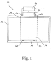
- the Fig. 1 shows an arrangement 10 for the powder bed-based additive manufacturing of a component (cf. Fig. 2 ) according to an embodiment of the invention.
- the arrangement 10 comprises a housing 12, a construction volume 14, a construction field 16, four marker devices 20, four laser devices 30, a control unit 40 and a removable reference marking plate 50.
- the construction field 16 is a 2-dimensional cross-sectional plane of the construction volume 14, which covers a section of an inner floor surface of the housing 12. Like in the Figure 1 shown, the construction field 16 corresponds to a vertical projection of the construction volume 14 onto the aforementioned bottom surface of the housing 12. The construction volume 14 corresponds to a volume subsection of the interior of the housing 12, which is marked in the figure with dashed lines.
- the four marker devices 20 are attached to the housing 12 so that they can follow thermodynamically caused deformations of the housing 12.
- Each of the marker devices 20 is suitable for projecting a light reference marking onto the construction field 16 or onto a component lying on the construction field 16.
- the marker devices 20 are arranged on an upper side of the housing 12 outside the housing.
- the four laser devices 30 are arranged above the housing 12 and are suitable for processing the entire construction field 16 in parallel to produce a component using additive manufacturing.
- the housing 12 has a translucent section 19, which spatially corresponds to the construction volume 14 and lies above the construction area 16. Both the laser devices 30 and the marker devices 20 are in optical contact with the construction volume 14 or the construction field 16 through the translucent section 19 of the housing 12.
- the reference marking plate 50 is a glass plate which lies on the inner bottom surface of the housing 12 and is congruent with the construction area 16.
- the reference mark plate 50 has four reference marks 52 etched onto an upper surface of the reference mark plate 50.
- the reference markings 52 lie on the construction field 16 and can be viewed as reference markings of the construction field 16.
- the control unit 40 is functionally connected to the laser devices 30 and the marking devices 20 and is set up to calibrate the laser devices 30 and synchronize them with one another.
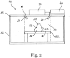
- the Fig. 2 shows an arrangement 10 for powder bed-based additive manufacturing of a component 100 according to another embodiment of the invention. Elements of the arrangement 10, which are in the Fig. 1 illustrated embodiment are also present, are marked with the same reference numerals as in the Fig. 1 . The elements that perform the same function in this embodiment as in the one in relation to Fig. 1 Embodiment already described will not be explained repeatedly.
- the component 100 is formed on a movable support member 102 displaceable along a vertical direction, which is moved after each Application of a layer of powder material can move downwards so that the distance between the top layer of powder material and the laser devices remains constant.
- the order 10 of the Fig. 2 differs from that of Fig. 1 further in that it comprises a cover element 18 which covers the housing 12 and forms an upper side or upper outer wall of the housing 12.
- the cover element 18 has a translucent section 19 which corresponds to the translucent section 19 of the housing Fig. 1 corresponds.
- the laser devices 30 are in optical contact with the construction volume 16 or the component 100 through the translucent section 19 of the cover element 18.
- the marker devices 20 in this embodiment are attached to the cover element 18 within the housing 12.
- the figure also shows a component 100 that is manufactured in the construction volume 14.
- Each of the marker devices 20 projects a light reference mark 22 onto the component 100.
- the marker devices 20 are set up to generate light for generating the light reference marks 22, which has wavelengths in the range between 490 nm and 540 nm.
- the construction field 16 has reference markings 17 which are chromatized on a bottom surface of the housing 12 and are covered by the component 100 in the situation shown.
- the Fig. 3 shows a schematic representation of some of the components of one of the laser devices 30 of an arrangement according to an embodiment of the invention.
- the laser device 30 comprises a deflection unit with a first scanning mirror 35 and a second scanning mirror 36, as well as a wavelength-selective optical element 38 and a detection device 34.
- the laser device 30 further comprises a laser light source 33 for generating the laser light that is used for laser processing of the component.
- the wavelength-selective optical element 38 is arranged on the light path, which is followed by the laser light generated by the laser light source 33 and/or the light to be detected by the detection device 34, between the deflection unit, ie the scanning mirrors 35 and 36, and the laser light source 33.
- the deflection unit is designed to deflect and scan light.
- the first scanning mirror 35 is configured to deflect and scan light in a first direction
- the second scanning mirror 36 is configured to deflect and scan light in a second direction, the first direction and the second direction perpendicular to each other.
- the scanning mirrors 35 and 36 of the deflection unit are set up to reflect light that has entered the laser device 30 in the direction of the detection device 34 through the optical element 38.
- the wavelength-selective optical element 38 is designed to be transparent to a wavelength range of the light of the light reference markings 22 reflected by the scanning mirrors 35 and 36 and entering the laser device 30 from the construction volume, so that this light is directed towards the detection device 34 is transmitted and recorded by it.
- This wavelength range of the light directed at the detection device 34 is optimized for the detection settings of the detection device 34.
- the detection device 34 is arranged along the light path followed by the light entering the laser device 30 after the first scanning mirror 35, the second scanning mirror 36 and the optical element 38.
- the wavelength-selective optical element 38 is further reflective of laser light generated from the laser light source 33 of the laser device 30 for laser processing a component, so that the laser light generated from the laser light source 33 is reflected by the first scanning mirror 35 and the second scanning mirror 36 in Direction is reflected on the building volume.
- the positionings and/or angle settings of the first scanning mirror 35 and the second scanning mirror 36 can be adjusted, for example, by corresponding galvanometers in order to deflect the laser light towards a target point of the construction volume and to pass through the light from the light reference markings 22 that enters the laser device to deflect the wavelength-selective optical element 38 in the direction of the detection device.
- the laser light is signaled in the figure by an arrow pointing downward from the laser light source 33.
- the detection device 34 comprises a camera 39 and a lens 37, which is specially configured for the detection of the light reference markings and the reference markings and may include an autofocusing lens which may be configured to focus the light detection by the detection device 34.
- the camera 39 can be a monochromatic camera.
- the Fig. 4 shows a schematic representation of the working fields of four laser devices 30 of an arrangement according to an embodiment of the invention.
- Each of the Laser devices 30 of the arrangement in the Fig. 1 or 2 The embodiment shown is set up for laser processing of an associated square working field.
- First to fourth laser devices 30 are each set up for laser processing of a first to fourth working field 32a-32d.
- Each of the working fields 32a-32d covers an area of 608 mm x 608 mm in the embodiment shown.
- the center points of adjacent work fields are offset by 202.63 mm in the embodiment shown.
- the four working areas 32a-32d have a common overlap area 32, which is congruent with the construction area 16 in the embodiment shown.
- the square overlap area 32 forms the square construction area 16.
- the construction area 16 covers an area of approximately 402 mm x 402 mm.
- the four laser devices 30 are set up for simultaneous parallel laser processing of the construction area 16.
- the marker devices 20 could be set up to project their associated light reference markings 22 onto an outer edge line of the construction field 16.
- the four marker devices 20 in the Fig. 1 and 2 Embodiments shown can, for example, be set up to project one of the light reference markings 22 onto one of the corners of the square construction area 16.
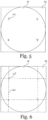
- the Figure 5 shows an exemplary distribution of the light reference markings 22 on a circular construction area 16 according to another embodiment of the invention.
- a square overlap area 32 of four laser devices 30 can be seen, which includes the circular construction area 16 but is not completely congruent with it.
- the Figure 6 shows an alternative embodiment in which instead of four cross-shaped light reference markings, as in the Fig. 5 , four laser lines 22 are projected, which cross each other in pairs at four intersection points 22 '.
- the laser lines 22 can each be generated by a line laser light source.
- the four laser lines 22 projected by the marker devices are perpendicular or parallel to one another in pairs and, as shown, form a laser marking square whose corner points correspond to the crossing points 22 '.
- the crossing points 22' can be recorded for calibration and/or synchronization.
- the detection of the crossing points 22' of the laser lines 22 represents a special case of the aforementioned detection of the light reference markings. It is understood that the laser lines 22 do not need to be detected over their entire length, but only in the area of the crossing points 22'.
- the Fig. 7 shows a flowchart illustrating a method 200 for calibrating and synchronizing the laser devices of an arrangement according to an embodiment of the invention.
- the method 200 can be applied to an arrangement according to any embodiment of the invention.
- the method is exemplified herein with reference to those in Fig. 1 and 2 embodiments shown are described.
- the method 200 includes a step 202 in which the marker devices 20 are adjusted so that the associated light reference marking 22 is brought into coincidence with one of the reference markings 17 and 52, respectively.
- the method 200 includes a step 204 in which each of the laser devices 30 detects at least three of the light reference marks 22 projected by the marker devices 20.
- the method 200 further includes a step 206 in which the individual laser devices 30 are calibrated based on the detected light reference marks 22.
- Calibration includes, in particular, the correction of an offset and the compensation of a gain drift, with which a deflection unit (which is not shown in the figures) of the associated laser device 30 can be affected.
- the calibration is carried out based on a selection among the light reference markings 22. With this selection, the light reference markings 22 which are further away from a center of the working field of the associated laser device are preferred.
- a first laser device 30, which is set up for laser processing of the working field 32a, can be calibrated, for example, based on the three light reference markings 22, which are further away from the center of the working field 32a than the light reference marking closest to this center. If the four marker devices 20 in the Fig. 1 and 2 For example, in the embodiments shown, one of the light reference markings 22 is projected onto one of the corners of the square construction field 16, the aforementioned closest light reference markings are located on the upper left corner of the square construction field 16. The first laser device can then be used in method step 206 the other three light reference markings 22 are calibrated, namely the light reference markings at the top right, bottom left and bottom right.
- the method 200 further includes a step 208 in which the four laser devices 30 of the arrangement are synchronized with one another based on the detected light reference marks.
- This step 208 may be omitted for arrangements that include only one laser device 30 according to some of the embodiments of the invention explained above.
- Method steps 206 to 208 can be carried out in any order, not necessarily the one in the Figure 7 must match the order shown.
- the method 200 may include repeating all method steps at regular intervals.
Description
Die vorliegende Erfindung betrifft eine Anordnung und ein Verfahren zur pulverbett-basierten additiven Fertigung eines Bauteils, und insbesondere die Kalibrierung und Synchronisierung mehrerer Laservorrichtungen zur parallelen Herstellung des Bauteils mit kombinierten Arbeitsfeldern.The present invention relates to an arrangement and a method for powder bed-based additive manufacturing of a component, and in particular to the calibration and synchronization of multiple laser devices for the parallel production of the component with combined working fields.
Additive Fertigungsverfahren, bei denen ein Werkstoff zur Erzeugung eines Bauteils schichtweise hinzugefügt und thermisch verarbeitet wird, gewinnen in der industriellen Produktion mehr und mehr an Bedeutung gegenüber den klassischen subtraktiven Fertigungsverfahren wie Fräsen, Bohren und Drehen, bei denen Material abgetragen wird, um ein Bauteil herzustellen. Die schichtbasierte Bauweise, die kennzeichnend für additive Fertigungsverfahren ist, ermöglicht die Herstellung hochkomplexer geometrischer Strukturen mit einem hohen Maß an Gestaltungsraum, das subtraktive Verfahren nicht erreichen können.Additive manufacturing processes, in which a material is added layer by layer and thermally processed to create a component, are becoming more and more important in industrial production compared to classic subtractive manufacturing processes such as milling, drilling and turning, in which material is removed to produce a component . The layer-based construction method, which is characteristic of additive manufacturing processes, enables the production of highly complex geometric structures with a high degree of design space that subtractive processes cannot achieve.
Die Zunahme in der industriellen Bedeutung der additiven Fertigungsverfahren wird von der steigenden Effizienz der Laserquellen vorangetrieben, die zur thermischen Bearbeitung eines Werkstoffes verwendet werden. Dementsprechend erfährt der Markt zurzeit einen Übergang von einer ursprünglichen Verwendung additiver Fertigungsverfahren lediglich zur Herstellung von Prototypen ("Rapid Prototyping") zu einem massenhaften industriellen Einsatz dieser Technologie für die Reihenproduktion ("Rapid Manufacturing"). Diese Entwicklung zeigt sich in zahlreichen Wirtschaftszweigen, wie beispielsweise der Luft-und Raumfahrtindustrie, der Automobilindustrie, der Medizintechnik und der Prothetik.The increase in the industrial importance of additive manufacturing processes is driven by the increasing efficiency of the laser sources used to thermally process a material. Accordingly, the market is currently experiencing a transition from an original use of additive manufacturing processes only for the production of prototypes (“rapid prototyping”) to a mass industrial use of this technology for series production (“rapid manufacturing”). This development can be seen in numerous economic sectors, such as the aerospace industry, the automotive industry, medical technology and prosthetics.
Eine besondere Art der additiven Fertigung stellen pulverbett-basierte Prozesse dar, bei denen ein pulverisiertes Ausgangsmaterial schichtweise auf das herzustellende Bauteil aufgetragen und durch Laserlicht aufgeschmolzen wird. Die Pulverschichten weisen typischerweise Dicken im Mikrometerbereich auf.A special type of additive manufacturing is powder bed-based processes, in which a powdered starting material is applied layer by layer to the component to be manufactured and melted using laser light. The powder layers typically have thicknesses in the micrometer range.
Eine wesentliche Rolle bei der Steigerung der Effizienz von Anordnungen zur pulverbett-basierten additiven Fertigung von Bauteilen spielt die Möglichkeit der Parallelverarbeitung eines Bauteils durch mehrere Laservorrichtungen, durch die höhere Ausstoßraten erreicht werden können. Der kombinierte Einsatz mehrerer Laservorrichtungen zur gleichzeitigen Herstellung eines Bauteils erfordert unbedingt eine genaue Kalibrierung der einzelnen Laservorrichtungen und eine Synchronisierung der Laservorrichtungen miteinander. Dies ist jedoch mit Schwierigkeiten verbunden, für die es noch keine Lösung gibt. Gängige Kalibrierungssysteme für Anordnungen zur additiven Fertigung eines Bauteils basieren auf der Justierung einzelner Galvanometer-Scanner (sogenannter Galvo-Motoren) der Laservorrichtungen und können temperaturbedingte Ungenauigkeiten der gesamten Anordnung nicht kollektiv berücksichtigen.The possibility of parallel processing of a component by several laser devices, through which higher output rates can be achieved, plays an important role in increasing the efficiency of arrangements for powder bed-based additive manufacturing of components. The combined use of several laser devices at the same time Manufacturing a component absolutely requires precise calibration of the individual laser devices and synchronization of the laser devices with one another. However, this poses difficulties for which there is still no solution. Common calibration systems for arrangements for the additive manufacturing of a component are based on the adjustment of individual galvanometer scanners (so-called galvo motors) of the laser devices and cannot collectively take temperature-related inaccuracies of the entire arrangement into account.
Somit besteht bei der additiven Fertigung von Bauteilen Verbesserungsbedarf im Hinblick auf die Kalibrierung und Synchronisierung mehrerer parallel arbeitender Laservorrichtungen.There is therefore a need for improvement in the additive manufacturing of components with regard to the calibration and synchronization of several laser devices working in parallel.
Aus der
Die
Der vorliegenden Erfindung liegt die Aufgabe zu Grunde, die Kalibrierung, Re-Kalibrierung und Synchronisierung einer oder mehrerer an der pulverbett-basierten additiven Fertigung eines Bauteils parallel beteiligten Laservorrichtungen zu gestatten. Hierbei ist mit "parallel" insbesondere ein vollparallelisiertes Fertigungsverfahren gemeint, bei dem mehrere an der Fertigung beteiligte Laservorrichtungen die Herstellung des Bauteils durch gleichzeitige Bearbeitung eines gemeinsamen Baufeldes zusammenwirkend bewerkstelligen. Diese Aufgabe wird durch eine Anordnung nach Anspruch 1, ein Verfahren nach Anspruch 12, ein Computerprogrammprodukt nach Anspruch 18 und ein computerlesbares Speichermedium nach Anspruch 19 gelöst. Bevorzugte Ausführungsformen und Weiterbildungen der Erfindung sind in den abhängigen Ansprüchen angegeben.The present invention is based on the object of allowing the calibration, recalibration and synchronization of one or more laser devices involved in parallel in the powder bed-based additive manufacturing of a component. Here, “parallel” means in particular a fully parallel manufacturing process in which several laser devices involved in the manufacturing work together to produce the component by simultaneously processing a common construction area. This object is achieved by an arrangement according to
Die vorliegende Erfindung betrifft eine Anordnung zur pulverbett-basierten additiven Fertigung eines Bauteils. Die Anordnung umfasst ein Gehäuse, das ein Bauvolumen umfasst, wobei das Bauvolumen ein Baufeld umfasst. Das Baufeld ist eine 2-dimensionale Querschnittsebene des Bauvolumens und deckt eine Oberfläche des Gehäuses ab, auf der das Bauteil durch sukzessiven Pulverbettauftragungen und daran anschließende thermische Verarbeitung schichtweise erzeugt werden kann. Das Baufeld entspricht typischerweise einer vertikalen Projektion des 3-dimensionalen Bauvolumens. Dies bedeutet zum Beispiel, dass bei einem zylinderförmigen Bauvolumen, das Baufeld einer kreisförmigen Querschnittsebene entsprechen kann, und bei einem würfelförmigen Bauvolumen das Baufeld einer quadratischen Querschnittsebene entsprechen kann, wobei beliebige Formen des Bauvolumens möglich sind. Das Bauvolumen kann beispielsweise einem gesonderten Volumenunterabschnitt des Innenraums des Gehäuses entsprechen, und das Baufeld kann einem entsprechen Flächenabschnitt einer unteren Oberfläche des Gehäuses abdecken, der eine 2-dimensionale Projektion des Bauvolumens auf die untere Oberfläche des Gehäuses darstellt. Das Baufeld kann ebenfalls eine bewegliche Oberfläche abdecken, auf der eine oberste Pulverbettschicht des Ausgangsmaterials aufliegt. Die bewegliche Oberfläche kann in diesem Fall nach der Laserverarbeitung einer jeden Pulverbettschicht entlang einer Richtung derart verschoben werden, dass ein Abstand zwischen dem Baufeld bzw. der obersten Pulverbettschicht des zu bearbeitenden Ausgangsmaterials und den Laservorrichtungen konstant bleibt.The present invention relates to an arrangement for the powder bed-based additive manufacturing of a component. The arrangement includes a housing that includes a construction volume, whereby the construction volume includes a construction area. The construction area is a 2-dimensional cross-sectional plane of the construction volume and covers a surface of the housing on which the component can be created layer by layer through successive powder bed applications and subsequent thermal processing. The construction area typically corresponds to a vertical projection of the 3-dimensional building volume. This means, for example, that in the case of a cylindrical building volume, the building field can correspond to a circular cross-sectional plane, and in the case of a cube-shaped building volume, the building field can correspond to a square cross-sectional plane, with any shape of the building volume being possible. The construction volume can, for example, correspond to a separate volume subsection of the interior of the housing, and the construction area can cover a corresponding surface section of a lower surface of the housing, which represents a 2-dimensional projection of the construction volume onto the lower surface of the housing. The construction area can also cover a movable surface on which a top powder bed layer of the starting material rests. In this case, after laser processing of each powder bed layer, the movable surface can be moved along a direction such that a distance between the construction field or the top powder bed layer of the starting material to be processed and the laser devices remains constant.
Man beachte jedoch, dass es sich sowohl bei dem Bauvolumen als auch bei dem Baufeld um virtuelle geometrische Konstrukte handeln kann, die einen bestimmten räumlichen Bereich der Anordnung abdecken können aber keine körperliche Natur besitzen müssen. Zwar kann sich das Baufeld beispielsweise über einen gesonderten Flächenabschnitt des Gehäuses der Anordnung erstrecken, muss jedoch nicht unbedingt mit diesem gesonderten Flächenabschnitt identifiziert werden. Entsprechendes gilt für das Bauvolumen.Please note, however, that both the building volume and the building field can be virtual geometric constructs that can cover a certain spatial area of the arrangement but do not have to have a physical nature. Although the construction area can, for example, extend over a separate surface section of the housing of the arrangement, it does not necessarily have to be identified with this separate surface section. The same applies to the construction volume.
Das Bauvolumen kann durch das Gehäuse von einer Umgebung isoliert werden, wodurch störende Wechselwirkungen der Umgebung mit dem Bauvolumen vermieden werden können, um die Erhaltung der für die additive Fertigung des Bauteils im Bauvolumen erforderlichen physikalischen Bedingungen wie beispielsweise Druck, Temperatur, Luftfeuchtigkeit, Reinheit der Atmosphäre usw. zu gewährleisten. Das Gehäuse kann jedoch eine optische Wechselwirkung mit dem Bauvolumen von Außerhalb des Gehäuses ermöglichen, beispielsweise durch einen lichtdurchlässigen Abschnitt des Gehäuses. Ein lichtdurchlässiger Abschnitt des Gehäuses kann mit dem Bauvolumen bzw. dem Baufeld räumlich übereinstimmen, um. die visuelle Beobachtung und optische Beobachtung des Fertigungsverfahrens im Bauvolumen sowie eine optische Einwirkung auf das Bauvolumen von außerhalb des Gehäuses zu ermöglichen.The construction volume can be isolated from an environment by the housing, whereby disruptive interactions between the environment and the construction volume can be avoided in order to maintain the physical conditions required for the additive manufacturing of the component in the construction volume, such as pressure, temperature, humidity, and purity of the atmosphere etc. to ensure. However, the housing can enable optical interaction with the construction volume from outside the housing, for example through a translucent section of the housing. A translucent section of the housing can spatially correspond to the construction volume or the construction area in order to. to enable visual observation and optical observation of the manufacturing process in the construction volume as well as an optical influence on the construction volume from outside the housing.
Die Anordnung umfasst ferner mindestens zwei, vorzugsweise mindestens drei Markervorrichtungen, die in oder an dem Gehäuse befestigt sind, wobei jede Markervorrichtung dazu geeignet ist, eine Lichtreferenzmarkierung auf ein auf dem Baufeld liegendes Bauteil und/oder auf das Baufeld zu projizieren. Die Markervorrichtungen sind vorzugsweise an dem Gehäuse derart befestigt, dass die Markervorrichtungen thermodynamisch bedingten Verformungen mindestens eines Teils des Gehäuses folgen können. Die Markervorrichtungen können innerhalb oder außerhalb des Gehäuses angeordnet sein. Wenn sie außerhalb des Gehäuses angeordnet sind, sind die Markervorrichtungen allerdings derart angeordnet, dass sie optischen Kontakt mit dem Baufeld und dem Bauteil herstellen können, beispielsweise durch einen lichtdurchlässigen Teil des Gehäuses.The arrangement further comprises at least two, preferably at least three marker devices which are attached in or on the housing, each marker device being suitable for projecting a light reference marking onto a component lying on the construction area and/or onto the construction area. The marker devices are preferably attached to the housing in such a way that the marker devices can follow thermodynamically induced deformations of at least part of the housing. The marker devices can be arranged inside or outside the housing. However, when they are arranged outside the housing, the marker devices are arranged in such a way that they can establish optical contact with the construction field and the component, for example through a translucent part of the housing.
Durch die Befestigung der Markervorrichtungen in oder an dem Gehäuse kann erreicht werden, dass sich unkontrollierte thermomechanische Verformungen des Gehäuses oder Dehnungen eines Teils hiervon, gleichermaßen auf das Bauvolumen und auf die Position der Lichtreferenzmarkierungen auswirken. Solche Verformungen und Dehnungen können sich zum Beispiel im Laufe des Fertigungsprozesses infolge von Temperaturänderungen im Bauvolumen ergeben. Auf diese Weise kann das Problem vermieden oder abgemildert werden, dass die Positionierung der Lichtreferenzmarkierungen auf dem Baufeld bzw. auf dem Bauteil von den vorgenannten Effekten unkontrolliert beeinflusst werden. Stattdessen bewegen sich die Markervorrichtungen im Falle von Dehnungen oder Verformungen des Gehäuses zumindest teilweise mit dem Gehäuse mit, sodass die relativen Positionen der von den Markervorrichtungen projizierten Lichtreferenzmarkierungen in Bezug auf das Bauvolumen und/oder auf das Baufeld beibehalten werden können.By attaching the marker devices in or on the housing, it can be achieved that uncontrolled thermomechanical deformations of the housing or expansion of a part thereof have an equal effect on the construction volume and on the position of the light reference markings. Such deformations and expansions can occur, for example, during the manufacturing process as a result of temperature changes in the construction volume. In this way, the problem can be avoided or mitigated that the positioning of the light reference markings on the construction field or on the component is influenced in an uncontrolled manner by the aforementioned effects. Instead, in the event of expansion or deformation of the housing, the marker devices move at least partially with the housing, so that the relative positions of the light reference markings projected by the marker devices with respect to the construction volume and/or to the construction field can be maintained.
Die Markervorrichtungen weisen eine sehr hohe Zeigestabilität auf, so dass neben dem erwähnten gewünschten "Mitdriften" mit dem Gehäuse infolge thermodynamisch bedingter Verformungen oder Dehnungen kein weiterer Drift auf die Markervorrichtungen einwirkt.The marker devices have a very high pointing stability, so that in addition to the aforementioned desired "drifting" with the housing as a result of thermodynamically caused deformations or expansions, no further drift affects the marker devices.
Es versteht sich, dass die Lichtreferenzmarkierungen direkt auf das Baufeld projiziert werden, wenn kein Bauteil in dem Bauvolumen enthalten ist bzw. hergestellt wird. Liegt ein Bauteil auf dem Baufeld, sei es ein fertig hergestelltes Bauteil oder ein Bauteil das gerade hergestellt wird, können die Lichtreferenzmarkierungen sowohl auf das Bauteil, d.h. auf eine oberste - möglicherweise noch zu verarbeitende - Pulverschicht des Bauteils, als auch auf Bereiche des Baufeldes, die von dem Bauteil nicht abgeschirmt werden, projiziert werden. Zudem bietet dies den Vorteil, dass die Position der Lichtreferenzmarkierungen unabhängig von dem Entwicklungsstand des Bauteils während der Fertigung ist, da die Lichtreferenzmarkierungen immer auf eine oberste Pulverschicht des Bauteils projiziert werden können.It is understood that the light reference markings are projected directly onto the construction area if no component is contained or is being manufactured in the construction volume. If there is a component on the construction site, be it a finished component or a component that is currently being manufactured, the light reference markings can be applied both to the component, ie to an uppermost powder layer of the component - possibly still to be processed - as well as to areas of the construction area. that are not shielded by the component are projected. This also offers the advantage that the position of the light reference markings is independent of the development status of the component during production, since the Light reference markings can always be projected onto a top powder layer of the component.
Die Anordnung umfasst ferner eine Laservorrichtung zur Laserverarbeitung eines Pulverbetts zur Erzeugung eines Bauteils auf dem Baufeld mittels additiver Fertigung. Die Laservorrichtung ist zur Laserbearbeitung eines zugehörigen Arbeitsfeldes eingerichtet.The arrangement further comprises a laser device for laser processing of a powder bed to produce a component on the construction field using additive manufacturing. The laser device is set up for laser processing of an associated work area.
Die Laservorrichtung kann über dem Gehäuse angeordnet und dazu eingerichtet sein, durch einen lichtdurchlässigen Teil des Gehäuses mit dem Bauvolumen bzw. dem Baufeld und oder mit einem im Bauvolumen liegenden Bauteil optisch wechselzuwirken. Diese optische Wechselwirkung kann sowohl der Laserbearbeitung eines Pulvermaterials zum Zwecke der additiven Fertigung des Bauteils als auch der Kalibrierung der Anordnung dienen.The laser device can be arranged above the housing and set up to optically interact with the construction volume or the construction area and/or with a component located in the construction volume through a translucent part of the housing. This optical interaction can be used both for laser processing of a powder material for the purpose of additive manufacturing of the component and for calibrating the arrangement.
Hierin wird unter "Laservorrichtung" eine Vorrichtung verstanden, die zur Laserbearbeitung des zur Herstellung des Bauteils verwendeten Pulvers im Rahmen der additiven Fertigung geeignet ist. Insbesondere kann eine Laservorrichtung eine Ablenkeinheit, auch Ablenkkopf genannt, umfassen, die es ermöglicht, das gesamte Bauvolumen zu scannen, und die das punktgenaue lasergesteuerte Aufschmelzen des zur Herstellung des Bauteils verwendeten Pulvers steuern kann. Für die hierin beschriebene Anordnung eignen sich insbesondere die Ablenkeinheiten, die Gegenstand der Patentanmeldung
Ferner umfasst die Laservorrichtung eine Detektionseinrichtung, die dazu eingerichtet ist, die Lichtreferenzmarkierungen zu erfassen. Die Erfassung der Lichtreferenzmarkierungen von der Detektionseinrichtung kann durch optische Detektion des von dem Baufeld bzw. von dem Bauteil reflektierten Lichts der Lichtreferenzmarkierungen erfolgen. Diese Detektion kann eine mechanisch gesteuerte Anpassung der Komponenten der Laservorrichtung, wie beispielsweise Spiegel, Linsen, Galvanometer, Ablenkeinheiten, oder anderer optischer und/oder elektronischer Elemente, umfassen. Die Lichtreferenzmarkierungen können dabei vollständig erfasst werden. Alternativ können die Lichtreferenzmarkierungen aber auch teilweise erfasst werden, sodass lediglich ausgewählte Bereiche oder Teile einer oder mehrerer der Lichtreferenzmarkierungen erfasst werden. Beide Varianten werden durch den Begriff "Erfassen der Lichtreferenzmarkierungen" abgedeckt.The laser device further comprises a detection device which is set up to detect the light reference markings. The detection of the light reference markings by the detection device can take place by optically detecting the light of the light reference markings reflected from the construction field or from the component. This detection may include a mechanically controlled adjustment of the components of the laser device, such as mirrors, lenses, galvanometers, deflection units, or other optical and/or electronic elements. The light reference markings can be completely captured. Alternatively, the light reference markings can also be partially detected, so that only selected areas or parts of one or more of the light reference markings are detected. Both variants are covered by the term “acquiring the light reference markings”.
Die Erkennung der Lichtreferenzmarkierungen durch die Detektionseinrichtung und eine anschließende Justierung der Laservorrichtung auf die Lichtreferenzmarkierungen kann durch eine geeignete Software gesteuert werden. Die interne Struktur und die Funktionsweise einer Laservorrichtung, einschließlich der vorgenannten Software, sind aus dem Stand der Technik bekannt und werden hierin nicht im Detail beschrieben. Stattdessen wird für weitere Details auf die vorgenannte Patentanmeldung
Die Anordnung umfasst ferner eine Steuereinheit, die dazu eingerichtet ist, basierend auf den von der Detektionseinrichtung erfassten Lichtreferenzmarkierungen die Laservorrichtung zu kalibrieren. Zu diesem Zweck kann die Steuereinheit einen Prozessor umfassen, auf dem eine hierzu geeignete Software ausgeführt werden kann, und einen Speicher, in dem die Software gespeichert ist. Anhand dieser Kalibrierung, die auf den von den Markervorrichtungen erzeugten Lichtreferenzmarkierungen basiert, ermöglicht die erfindungsgemäße Anordnung einen präzisen Betrieb der Laservorrichtung zur Herstellung des Bauteils im Rahmen der additiven Fertigung.The arrangement further comprises a control unit which is set up to calibrate the laser device based on the light reference markings detected by the detection device. For this purpose, the control unit can comprise a processor on which suitable software can be executed and a memory in which the software is stored. Using this calibration, which is based on the light reference markings generated by the marker devices, the arrangement according to the invention enables precise operation of the laser device for producing the component in the context of additive manufacturing.
Betriebsbedingte Temperaturschwankungen der Laservorrichtungen können die Genauigkeit der Laservorrichtungen in Form eines Offset-Drifts und/oder eines Gain-Drifts beeinträchtigen. Diese können verursachen, dass ein von einer Laservorrichtung bzw. dem Prozessor einer Laservorrichtung bestimmter Punkt in Bezug auf das Bauvolumen "wandert" bzw. sich ändert, so dass der Punkt des Bauvolumens, der von der Laservorrichtung tatsächlich getroffen wird, wenn ein bestimmter Punkt anvisiert wird, sich im Laufe der Zeit ändert. Durch die Kalibrierung wird die Laservorrichtung darauf eingestellt, einen gewünschten, anvisierten Punkt des Bauvolumens zum Zwecke der Laserbearbeitung tatsächlich zu treffen. Insbesondere können durch die Kalibrierung die Effekte eines Offset-Drifts und/oder eines Gain-Drifts kompensiert bzw. korrigiert werden.Operational temperature fluctuations of the laser devices can affect the accuracy of the laser devices in the form of offset drift and/or gain drift. These can cause a point determined by a laser device or the processor of a laser device to "migrate" or change with respect to the build volume, so that the point of the build volume that is actually hit by the laser device when targeting a particular point will change over time. Through calibration, the laser device is adjusted to actually hit a desired, targeted point of the construction volume for the purpose of laser processing. In particular, the effects of an offset drift and/or a gain drift can be compensated or corrected by the calibration.
Die erfindungsgemäße Anordnung gestattet eine Kalibrierung der Laservorrichtung, bei der negative Effekte von betriebsbedingten Ungenauigkeitsquellen auf die Präzision der Anordnung berücksichtigt werden können. Dies ermöglicht eine erhöhte Positionsgenauigkeit der Laserbearbeitung des Bauteils durch die Laservorrichtung in der Anordnung, die sich letztendlich in einer erhöhten Qualität des gefertigten Bauteils widerspiegelt.The arrangement according to the invention allows calibration of the laser device, in which negative effects of operational sources of inaccuracy on the precision of the arrangement can be taken into account. This enables increased positional accuracy of the laser processing of the component by the laser device in the arrangement, which is ultimately reflected in an increased quality of the manufactured component.
Gemäß einer bevorzugten Ausführungsform sind mindestens drei der Markervorrichtungen dazu geeignet, jeweils eine linienförmige Lichtreferenzmarkierung zu projizieren, wobei die linienförmigen Lichtreferenzmarkierungen sich paarweise an mindestens drei zugehörigen Kreuzungspunkten kreuzen. Die Detektionseinrichtung ist dazu eingerichtet, die mindestens drei Kreuzungspunkte zu erfassen, und die Steuereinheit ist ferner dazu eingerichtet, die Laservorrichtung (30) basierend auf den mindestens drei von der Detektionseinrichtung erfassten Kreuzungspunkten zu kalibrieren. Die Verwendung von Kreuzungspunkten zur Kalibrierung, an denen sich linienförmige Lichtreferenzmarkierungen kreuzen, ermöglicht ein besseren Driftverhaltens und eine bessere Abbildungsschärfe.According to a preferred embodiment, at least three of the marker devices are suitable for each projecting a line-shaped light reference marking, the line-shaped light reference markings crossing in pairs at at least three associated intersection points. The detection device is set up to detect the at least three crossing points, and the control unit is further set up to calibrate the laser device (30) based on the at least three crossing points detected by the detection device. The use of intersection points for Calibration, where line-shaped light reference marks intersect, enables better drift behavior and better image sharpness.
In einer bevorzugten Ausführungsform umfasst die Anordnung eine Mehrzahl von Laservorrichtungen. Jede Laservorrichtung ist zur Laserbearbeitung eines zugehörigen Arbeitsfeldes eingerichtet. Die Arbeitsfelder der jeweiligen Laservorrichtungen decken eine gemeinsame Überlappungsfläche ab. Diese gemeinsame Überlappungsfläche kann dem Baufeld entsprechen, d.h. kann deckungsgleich mit dem Baufeld sein. Dies kann beispielsweise der Fall sein, wenn die Arbeitsfelder der einzelnen Laservorrichtungen eine gemeinsame quadratische Überlappungsfläche abdecken und das Baufeld ein quadratisches Baufeld ist. Die gemeinsame Überlappungsfläche kann jedoch das Baufeld umfassen ohne mit diesem deckungsgleich zu sein. Dies kann beispielsweise der Fall sein, wenn die Arbeitsfelder der einzelnen Laservorrichtungen eine gemeinsame quadratische Überlappungsfläche abdecken, das Baufeld aber ein kreisförmiges Baufeld ist.In a preferred embodiment, the arrangement comprises a plurality of laser devices. Each laser device is set up for laser processing of an associated working area. The working fields of the respective laser devices cover a common overlapping area. This common overlap area can correspond to the construction area, i.e. can be congruent with the construction area. This can be the case, for example, if the working fields of the individual laser devices cover a common square overlap area and the construction field is a square construction field. However, the common overlap area can encompass the construction area without being congruent with it. This can be the case, for example, if the working fields of the individual laser devices cover a common square overlap area, but the construction field is a circular construction field.
Jede der Laservorrichtungen kann ein eigenes Arbeitsfeld abdecken bzw. bearbeiten, das sich zumindest teilweise mit den Arbeitsfeldern der restlichen Laservorrichtungen überlappt. Die Mehrzahl von Laservorrichtungen sind zur gleichzeitigen parallelen Laserbearbeitung dieser gemeinsamen Überlappungsfläche, die dem Baufeld entspricht oder das Baufeld umfasst, eingerichtet. Die Laservorrichtungen können über dem Gehäuse angeordnet und dazu eingerichtet sein, durch einen lichtdurchlässigen Teil des Gehäuses mit dem Bauvolumen bzw. dem Baufeld und oder mit einem im Bauvolumen liegenden Bauteil optisch wechselzuwirken. Diese optische Wechselwirkung kann sowohl der Laserbearbeitung eines Pulvermaterials zum Zwecke der additiven Fertigung des Bauteils als auch der Kalibrierung und Synchronisierung der Anordnung dienen.Each of the laser devices can cover or process its own working field, which at least partially overlaps with the working fields of the remaining laser devices. The plurality of laser devices are set up for simultaneous parallel laser processing of this common overlap area, which corresponds to the construction field or includes the construction field. The laser devices can be arranged above the housing and set up to optically interact with the construction volume or the construction field and/or with a component lying in the construction volume through a translucent part of the housing. This optical interaction can be used for laser processing of a powder material for the purpose of additive manufacturing of the component as well as for calibration and synchronization of the arrangement.
Die Steuereinheit ist dann ferner dazu eingerichtet ist, basierend auf den von den Detektionseinrichtungen erfassten Lichtreferenzmarkierungen und/oder Kreuzungspunkten die Mehrzahl von Laservorrichtungen zu kalibrieren und/oder verschiedene Laservorrichtungen miteinander zu synchronisieren. Anhand dieser Synchronisierung, die auf den von den Markervorrichtungen erzeugten Lichtreferenzmarkierungen und/oder Kreuzungspunkten basiert, ermöglicht die erfindungsgemäße Anordnung einen präzisen gleichzeitigen parallelen Betrieb der Mehrzahl von Laservorrichtungen zur parallelen Herstellung des Bauteils im Rahmen der additiven Fertigung. Dadurch wird eine verbesserte Synchronisierung der Laservorrichtungen miteinander erzielt.The control unit is then further set up to calibrate the plurality of laser devices and/or to synchronize different laser devices with one another based on the light reference markings and/or crossing points detected by the detection devices. Using this synchronization, which is based on the light reference markings and/or crossing points generated by the marker devices, the arrangement according to the invention enables precise, simultaneous, parallel operation of the plurality of laser devices for the parallel production of the component in the context of additive manufacturing. This results in improved synchronization of the laser devices with one another.
In einer bevorzugten Ausführungsform umfasst die Anordnung ferner ein Deckelement, das dazu geeignet ist, das Gehäuse abzudecken wobei die mindestens drei Markervorrichtungen vorzugsweise in oder an dem Deckelelement befestigt sind. "Abdecken" kann hierbei auf die Herstellung einer fluiddichten Verbindung zwischen dem Deckelelement und dem Gehäuse hinweisen, mit der störende mechanische oder chemische Wechselwirkungen der Umgebung mit dem Bauvolumen vermieden werden können, um die Erhaltung der für die additiven Fertigung des Bauteils im Bauvolumen erforderlichen physikalischen oder chemischen Bedingungen zu gewährleisten. Nichtsdestotrotz ermöglicht das Deckelelement eine optische Wechselwirkung mit dem Bauvolumen von Außerhalb des Gehäuses. Insbesondere kann das Deckelelement gänzlich oder teilweise lichtdurchlässig sein, um die visuelle Beobachtung und optische Überwachung des Fertigungsverfahrens sowie eine optische Einwirkung auf das Bauvolumen von außerhalb des Gehäuses zu ermöglichen. Das Deckelelement kann beispielsweise ein Glasfenster umfassen, welches mit dem Baufeld räumlich übereinstimmt und mithin das ganze Bauvolumen überdeckt.In a preferred embodiment, the arrangement further comprises a cover element which is suitable for covering the housing, the at least three marker devices preferably being fastened in or on the cover element. “Covering” can refer to the Establishment of a fluid-tight connection between the cover element and the housing, with which disruptive mechanical or chemical interactions of the environment with the construction volume can be avoided in order to ensure that the physical or chemical conditions required for the additive manufacturing of the component in the construction volume are maintained. Nevertheless, the cover element enables optical interaction with the construction volume from outside the housing. In particular, the cover element can be completely or partially translucent in order to enable visual observation and optical monitoring of the manufacturing process as well as an optical influence on the construction volume from outside the housing. The cover element can, for example, comprise a glass window, which spatially corresponds to the construction area and therefore covers the entire construction volume.
Gemäß einer bevorzugten Ausführungsform sind die mindestens drei Markervorrichtungen außerhalb des Gehäuses angeordnet. Die Markervorrichtungen sind dann durch das Gehäuse oder durch das Deckelelement von dem Innenraum des Gehäuses bzw. dem Bauvolumen getrennt. Dadurch kann der Betrieb der Markervorrichtungen stabilisiert werden. Gleichzeitig folgen die Markervorrichtungen, die gleichwohl am Deckelelement befestigt sind, temperaturbedingten Verformungen des Deckelelements, die erwartungsgemäß ähnlich sind wie die Verformungen, die sich für das Bauvolumen ergeben.According to a preferred embodiment, the at least three marker devices are arranged outside the housing. The marker devices are then separated from the interior of the housing or the construction volume by the housing or by the cover element. This allows the operation of the marker devices to be stabilized. At the same time, the marker devices, which are nevertheless attached to the cover element, follow temperature-related deformations of the cover element, which are, as expected, similar to the deformations that arise for the construction volume.
In einer bevorzugten Ausführungsform umfasst die Mehrzahl von Laservorrichtungen mindestens vier Laservorrichtungen, die dazu geeignet sind, das gesamte Baufeld zur Herstellung des Bauteils parallel zu bearbeiten. Die Anzahl der Markervorrichtungen kann dementsprechend ebenfalls mindestens vier sein, wobei die Anzahl der Markervorrichtungen nicht unbedingt mit der Anzahl der Laservorrichtungen übereinstimmen muss. Die Anzahl der Markervorrichtungen beträgt zwei oder mehr, vorzugsweise drei oder mehr. Man beachte, dass andere Konfigurationen mit einer beliebigen ersten Anzahl von Laservorrichtungen und einer beliebigen zweiten Anzahl von Markervorrichtungen ebenfalls möglich ist.In a preferred embodiment, the plurality of laser devices comprises at least four laser devices which are suitable for processing the entire construction field in parallel for producing the component. The number of marker devices can accordingly also be at least four, although the number of marker devices does not necessarily have to correspond to the number of laser devices. The number of marker devices is two or more, preferably three or more. Note that other configurations with any first number of laser devices and any second number of marker devices are also possible.
Gemäß einer bevorzugten Ausführungsform weist das Baufeld eine oder mehrere Referenzmarkierungen auf, und die Detektionseinrichtung mindestens einer der Laservorrichtungen ist ferner dazu eingerichtet, die eine oder die mehreren Referenzmarkierungen zu erfassen. Die Referenzmarkierungen können Markierungen jeglicher Art sein, beispielsweise geätzte oder chromatisierte Strukturen, aber auch optisch erzeugte Markierungen. Die Referenzmarkierungen können beispielsweise Markierungen sein, die auf einer mit dem Baufeld übereinstimmenden Oberfläche des Gehäuses durch Ätzen, Chromatierung oder dergleichen ausgebildet sind.According to a preferred embodiment, the construction field has one or more reference markings, and the detection device of at least one of the laser devices is further set up to detect the one or more reference markings. The reference markings can be markings of any kind, for example etched or chromatized structures, but also optically generated markings. The reference markings can be, for example, markings that are formed on a surface of the housing that corresponds to the construction area by etching, chromating or the like.
Die Erfassung der Referenzmarkierungen durch die Detektionseinrichtung mindestens einer der Laservorrichtungen kann durch den gleichen Mechanismus erfolgen, der für die Erfassung der Lichtreferenzmarkierungen wie oben ausgeführt verwendet wird. Insbesondere können für die Erfassung der Referenzmarkierungen die gleichen Komponenten der Erfassungseinrichtung verwendet werden wie für die Erfassung der Lichtreferenzmarkierungen.The detection of the reference markings by the detection device of at least one of the laser devices can be carried out by the same mechanism that is used for the detection of the light reference markings as stated above. In particular, the same components of the detection device can be used to detect the reference markings as for detecting the light reference markings.
Die Referenzmarkierungen ermöglichen eine Justierung der Markervorrichtungen auf das Baufeld. Die Markervorrichtungen können beispielsweise derart justiert werden, dass die zugehörige Lichtreferenzmarkierung eine vorbestimmte räumliche Beziehung zu einer oder mehreren der Referenzmarkierungen annimmt. Insbesondere können die Markervorrichtungen so justiert werden, dass eine oder mehrere der Lichtreferenzmarkierungen mit einer bzw. mehreren der Referenzmarkierungen in Deckung gebracht wird bzw. werden. Diese Justierung kann beispielsweise im Rahmen einer Grundjustierung vor der Herstellung des Bauteils stattfinden. Demnach werden die Markervorrichtungen vor Auftragung der ersten Pulverschicht anhand der Referenzvorrichtungen auf das Baufeld justiert. Nach Auftragung der sukzessiven Pulverschichten auf das Bauteil im Bauvolumen bleibt die genaue Positionierung der Referenzmarkierungen und mithin des Baufeldes durch die projizierten Lichtreferenzmarkierungen nachvollziehbar. Die eben beschriebene Grundeinstellung kann zu späteren Zeitpunkten zur erneuten Justierung der Anordnung wiederholt werden.The reference markings enable the marker devices to be adjusted to the construction field. The marker devices can, for example, be adjusted such that the associated light reference mark assumes a predetermined spatial relationship to one or more of the reference marks. In particular, the marker devices can be adjusted so that one or more of the light reference markings is or are brought into line with one or more of the reference markings. This adjustment can take place, for example, as part of a basic adjustment before the component is manufactured. Accordingly, the marker devices are adjusted to the construction field using the reference devices before the first powder layer is applied. After the successive layers of powder have been applied to the component in the construction volume, the exact positioning of the reference markings and therefore the construction area remains traceable through the projected light reference markings. The basic setting just described can be repeated at later times to readjust the arrangement.
Des Weiteren können die Laservorrichtungen anhand der Referenzmarkierungen auf das Baufeld justiert werden, wodurch die Laservorrichtungen die genaue Positionierung und das Ausmaß des Baufeldes erfassen können und gegebenenfalls die Einstellung ihrer optischen, mechanischen und oder elektromagnetischen Komponenten entsprechend anpassen. Die Justierung der Laservorrichtungen auf das Baufeld kann beispielsweise Einstellungen bezüglich einer Fokussierung, eines Strahlwinkels oder einer Strahlintensität umfassen
In einer bevorzugten Ausführungsform umfasst die Anordnung ferner eine abnehmbare Referenzmarkierplatte, die im oder auf dem Baufeld angeordnet werden kann und die eine oder die mehreren Referenzmarkierungen umfasst. Die Referenzmarkierplatte kann dazu geeignet sein, in den Innenraum des Gehäuses, beispielsweise auf eine untere Oberfläche des Gehäuses, aufgebracht zu werden. Die Referenzmarkierplatte ist vorzugsweise deckungsgleich mit dem Baufeld. Im Falle eines kreisförmigen Baufeldes kann die Referenzmarkierplatte beispielsweise eine scheibenförmige Platte sein. Die Referenzmarkierungen können Markierungen jeglicher Art sein, beispielsweise auf der Referenzmarkierplatte geätzte oder chromatisierte Strukturen, aber auch optisch erzeugte Markierungen.Furthermore, the laser devices can be adjusted to the construction field using the reference markings, whereby the laser devices can record the exact positioning and extent of the construction field and, if necessary, adjust the setting of their optical, mechanical and/or electromagnetic components accordingly. The adjustment of the laser devices to the construction field can include, for example, settings regarding focusing, a beam angle or a beam intensity
In a preferred embodiment, the arrangement further comprises a removable reference marking plate, which can be arranged in or on the construction field and which includes one or more reference markings. The reference marking plate can be suitable for being applied to the interior of the housing, for example on a lower surface of the housing. The reference marking plate is preferably congruent with the construction area. In the case of a circular construction area, the reference marking plate can be, for example, a disk-shaped plate. The reference markings can be markings of any kind, for example on the Reference marking plate etched or chromatized structures, but also optically generated markings.
Gemäß einem Aspekt der Erfindung umfassen mindestens drei der Markervorrichtungen eine Laserlichtquelle, die dazu eingerichtet ist, eine zugehörige Lichtreferenzmarkierung als punktförmige oder kreuzförmige Lichtreferenzmarkierung zu erzeugen.According to one aspect of the invention, at least three of the marker devices comprise a laser light source which is designed to generate an associated light reference mark as a point-shaped or cross-shaped light reference mark.
Gemäß einem Aspekt der Erfindung umfassen mindestens drei der Markervorrichtungen eine Laserlichtquelle, die dazu eingerichtet ist, eine zugehörige Lichtreferenzmarkierung als Laserlinie zu erzeugen, wobei sich die mindestens drei Laserlinien paarweise an insgesamt mindestens drei zugehörigen Kreuzungspunkten kreuzen. Beispielsweise können drei Markervorrichtungen drei Laserlinien erzeugen, die sich paarweise an drei zugehörigen Kreuzungspunkten kreuzen und ein Lasermarkierungs-Dreieck auf ein auf dem Baufeld liegendes Bauteil und/oder auf das Baufeld projizieren. Jeder Eckpunkt des Lasermarkierungs-Dreiecks entspricht einem Kreuzungspunkt zweier der Laserlinien. Auf ähnliche Weise können vier Markervorrichtungen beispielsweise vier Laserlinien erzeugen, die sich paarweise an vier zugehörigen Kreuzungspunkten kreuzen und ein Lasermarkierungs-Viereck bilden, wobei jeder Eckpunkt des Lasermarkierungs-Vierecks einem Kreuzungspunkt zweier der Laserlinien entspricht. Die vier von den Markervorrichtungen projizierten Laserlinien können insbesondere paarweise senkrecht bzw. parallel zueinander stehen, sodass das projizierte Lasermarkierungs-Viereck ein Rechteck oder ein Quadrat ist. Die Detektionseinrichtung und die Steuereinheit können dann derart eingerichtet sein, dass die Kreuzungspunkte der Lichtreferenzmarkierungen der Kalibrierung und/oder der Synchronisierung zu Grunde gelegt werden können.According to one aspect of the invention, at least three of the marker devices comprise a laser light source which is designed to generate an associated light reference mark as a laser line, the at least three laser lines crossing in pairs at a total of at least three associated intersection points. For example, three marker devices can generate three laser lines that cross each other in pairs at three associated intersection points and project a laser marking triangle onto a component lying on the construction field and/or onto the construction field. Each corner point of the laser marking triangle corresponds to an intersection point of two of the laser lines. In a similar manner, four marker devices can generate, for example, four laser lines that cross in pairs at four associated intersection points and form a laser marking quadrilateral, with each corner point of the laser marking quadrilateral corresponding to an intersection point of two of the laser lines. The four laser lines projected by the marker devices can in particular be in pairs perpendicular or parallel to one another, so that the projected laser marking square is a rectangle or a square. The detection device and the control unit can then be set up in such a way that the crossing points of the light reference markings can be used as a basis for the calibration and/or the synchronization.
Alternativ oder zusätzlich ist mindestens eine Markervorrichtung dazu eingerichtet, Licht zur Erzeugung der Lichtreferenzmarkierung zu erzeugen, das eine oder mehrere Wellenlängen zwischen 405 nm und 850 nm, vorzugweise zwischen 490 nm und 640 nm, besonders bevorzugt zwischen 490 nm und 540 nm hat.Alternatively or additionally, at least one marker device is set up to generate light for generating the light reference marking, which has one or more wavelengths between 405 nm and 850 nm, preferably between 490 nm and 640 nm, particularly preferably between 490 nm and 540 nm.
Gemäß einer weiteren bevorzugten Ausführungsform sind eine oder mehrere der Markervorrichtungen dazu eingerichtet, die zugehörige Lichtreferenzmarkierung auf eine Außenrandlinie des Baufeldes zu projizieren, oder in einem Abstand von der Außenrandlinie, der 10 % des Durchmessers des Baufeldes nicht übersteigt. Dies erweist sich als besonders vorteilhaft, wenn das Baufeld die Form eines Rechtecks aufweist, da die Lichtreferenzmarkierungen dann nicht nur die Positionierung des Baufeldes festlegen können, sondern auch seine genauen Maße und Außenränder. Im Falle eines kreisförmigen Baufeldes liegen die Lichtreferenzmarkierungen vorzugsweise innerhalb des Baufeldes.According to a further preferred embodiment, one or more of the marker devices are set up to project the associated light reference marking onto an outer edge line of the construction area, or at a distance from the outer edge line that does not exceed 10% of the diameter of the construction area. This proves to be particularly advantageous if the construction area has the shape of a rectangle, since the light reference markings can then not only determine the positioning of the construction area, but also its exact dimensions and outer edges. In the case of a circular construction area, the light reference markings are preferably located within the construction area.
In einer bevorzugten Ausführungsform umfasst mindestens eine der Laservorrichtungen eine Laserlichtquelle, die dazu eingerichtet ist, Laserlicht zur Laserverarbeitung eines Bauteils zu erzeugen, sowie eine Ablenkeinheit, die dazu eingerichtet ist, Licht abzulenken und zu scannen. Ferner umfasst die mindestens eine der Laservorrichtungen ein wellenlängenselektives optisches Element, das zwischen der Ablenkeinheit und der Laserlichtquelle angeordnet ist, und das für eine oder mehrere Wellenlängen des Laserlichts zumindest teilweise reflektierend ist und für eine oder mehrere Wellenlängen der Lichtreferenzmarkierungen zumindest teilweise durchlässig ist. Eine umgekehrte Konfiguration, in der das wellenlängenselektive optische Element für eine oder mehrere Wellenlängen des Laserlichts zumindest teilweise durchlässig ist und für eine oder mehrere Wellenlängen der Lichtreferenzmarkierungen zumindest teilweise reflektierend ist, ist je nach Position der Laserlichtquelle und der Detektionseinrichtung, ebenfalls möglich. Das wellenlängenselektive optische Element ist ferner dazu eingerichtet, das Licht der Lichtreferenzmarkierungen auszukoppeln und auf die Detektionseinrichtung zu richten.In a preferred embodiment, at least one of the laser devices comprises a laser light source that is set up to generate laser light for laser processing of a component, and a deflection unit that is set up to deflect and scan light. Furthermore, the at least one of the laser devices comprises a wavelength-selective optical element which is arranged between the deflection unit and the laser light source and which is at least partially reflective for one or more wavelengths of the laser light and is at least partially transparent for one or more wavelengths of the light reference markings. A reverse configuration, in which the wavelength-selective optical element is at least partially transparent to one or more wavelengths of the laser light and is at least partially reflective to one or more wavelengths of the light reference markings, is also possible, depending on the position of the laser light source and the detection device. The wavelength-selective optical element is also set up to decouple the light from the light reference markings and direct it towards the detection device.
Die Ablenkeinheit kann beispielsweise einen ersten Scannspiegel und einen zweiten Scannspiegel umfassen, wobei der erste Scannspiegel, dazu eingerichtet ist, Licht in eine erste Richtung abzulenken und zu scannen, und der zweite Scannspiegel dazu eingerichtet ist, Licht in eine zweite Richtung abzulenken und zu scannen, wobei die erste Richtung senkrecht zur zweiten Richtung steht. Die Detektionseinrichtung der Laservorrichtung ist dann auf einem Lichtpfad, dem in die Laservorrichtung eingetretenes Licht folgt, nach dem ersten Scannspiegel, dem zweiten Scannspiegel, d.h. nach der Ablenkeinheit, und dem optischen Element angeordnet. Man beachte, dass dieser Teil des Lichtpfades zumindest teilweise mit dem Lichtpfad übereinstimmen kann, den das zur Laserverarbeitung verwendete Licht - in umgekehrter Richtung - nimmt.The deflection unit can, for example, comprise a first scanning mirror and a second scanning mirror, wherein the first scanning mirror is designed to deflect and scan light in a first direction, and the second scanning mirror is designed to deflect and scan light in a second direction, where the first direction is perpendicular to the second direction. The detection device of the laser device is then arranged on a light path, which is followed by light entering the laser device, after the first scanning mirror, the second scanning mirror, i.e. after the deflection unit, and the optical element. Note that this part of the light path may at least partially coincide with the light path that the light used for laser processing takes - in the opposite direction.
Licht, das in die Laservorrichtung eintritt, wird in manchen Ausführungsformen von der Ablenkeinheit in Richtung des optischen Elements abgelenkt. Das auf das wellenlängenselektive optische Element tretende Licht wird von diesem ganz oder teilweise in Richtung auf die Detektionseinrichtung zur Erfassung transmittiert bzw. reflektiert. Von der Laserlichtquelle erzeugtes Licht zur Laserverarbeitung des Bauteils wird von dem wellenlängenselektiven optischen Element hingegen reflektiert und auf das Bauvolumen gerichtet, sodass sich an dieser Stelle der Lichtpfad für das Laserlicht und der Lichtpfad für die Detektion der Licht Referenzmarkierungen und/oder der Lichtreferenzmarkierungen trennt.In some embodiments, light entering the laser device is deflected by the deflection unit toward the optical element. The light incident on the wavelength-selective optical element is transmitted or reflected entirely or partially in the direction of the detection device for detection. Light generated by the laser light source for laser processing of the component is, however, reflected by the wavelength-selective optical element and directed onto the construction volume, so that the light path for the laser light and the light path for the detection of the light reference markings and/or the light reference markings separate at this point.
Selbstverständlich ist es ebenso möglich, ein wellenselektives optisches Element zu verwenden, welches das Laserlicht durchlässt und das von der Detektionseinrichtung zu erfassende Licht reflektiert. Zudem kann das wellenlängenselektive optische Element ein Teil des auf das optische Element tretenden Lichts in eine andere Richtung als die Richtung der Detektionseinrichtung ablenken, sodass dieser Teil des Lichts in der Laservorrichtung zu anderen Zwecken erfasst werden kann. Die Detektionseinrichtung kann beispielsweise eine monochromatische Kamera mit einem Objektiv umfassen, das für die Erfassung der Lichtreferenzmarkierungen und/oder der Referenzmarkierungen besonders konfiguriert ist. Die Detektionseinrichtung kann ferner eine Autofokussierlinse umfassen, um eine schärfere Erfassung der Lichtreferenzmarkierungen und/oder der Referenzmarkierungen durch die Kamera zu ermöglichen.Of course, it is also possible to use a wave-selective optical element, which allows the laser light to pass through and from the detection device detecting light reflected. In addition, the wavelength-selective optical element can deflect part of the light incident on the optical element in a direction other than the direction of the detection device, so that this part of the light can be detected in the laser device for other purposes. The detection device can, for example, comprise a monochromatic camera with a lens that is specially configured for detecting the light reference markings and/or the reference markings. The detection device can further comprise an autofocusing lens in order to enable a sharper detection of the light reference markings and/or the reference markings by the camera.
Die vorliegende Erfindung betrifft außerdem ein Verfahren zum Kalibrieren und/oder zum Synchronisieren der Laservorrichtung bzw. der Mehrzahl von Laservorrichtungen einer Anordnung zur pulverbett-basierten additiven Fertigung eines Bauteils gemäß einer der oben ausgeführten Ausführungsformen. Das Verfahren umfasst das Erfassen mindestens dreier Lichtreferenzmarkierungen mit der Laservorrichtung bzw. einer jeden der Laservorrichtungen. Ferner umfasst das Verfahren das Kalibrieren der Laservorrichtung bzw. der einzelnen Laservorrichtungen und/oder das Synchronisieren der Mehrzahl von Laservorrichtungen miteinander basierend auf den erfassten Lichtreferenzmarkierungen. Das Verfahren kann somit das Kalibrieren mindestens einer Laservorrichtung, das Synchronisieren einer Mehrzahl von Laservorrichtungen miteinander oder beides umfassen, wobei das Kalibrieren bzw. das Synchronisieren auf den erfassten Lichtreferenzmarkierungen basiert.The present invention also relates to a method for calibrating and/or synchronizing the laser device or the plurality of laser devices of an arrangement for powder bed-based additive manufacturing of a component according to one of the embodiments set out above. The method includes detecting at least three light reference marks with the laser device or each of the laser devices. The method further includes calibrating the laser device or the individual laser devices and/or synchronizing the plurality of laser devices with one another based on the detected light reference markings. The method may thus include calibrating at least one laser device, synchronizing a plurality of laser devices with one another, or both, wherein the calibration or synchronization is based on the detected light reference marks.
Gemäß einer bevorzugten Ausführungsform sind mindestens drei der Lichtreferenzmarkierungen linienförmig, wobei die linienförmigen Lichtreferenzmarkierungen sich paarweise an mindestens drei zugehörigen Kreuzungspunkten kreuzen. Das Erfassen der Lichtreferenzmarkierungen umfasst in solchen Ausführungsformen das Erfassen der mindestens drei Kreuzungspunkte. Das Erfassen der Lichtreferenzmarkierungen kann aber auch in solchen Ausführungsformen darin bestehen, die mindestens drei Kreuzungspunkte zu erfassen. Das Kalibrieren der Laservorrichtung bzw. der einzelnen Laservorrichtungen und/oder das Synchronisieren der Mehrzahl von Laservorrichtungen miteinander basiert auf den mindestens drei erfassten Kreuzungspunkten.According to a preferred embodiment, at least three of the light reference markings are linear, with the linear light reference markings crossing each other in pairs at at least three associated intersection points. In such embodiments, detecting the light reference markings includes detecting the at least three intersection points. However, in such embodiments, detecting the light reference markings can also consist of detecting the at least three crossing points. The calibration of the laser device or the individual laser devices and/or the synchronization of the plurality of laser devices with one another is based on the at least three detected crossing points.
In einer bevorzugten Ausführungsform umfasst mindestens eine der Laservorrichtungen eine Ablenkeinheit, mit der ein von der zugehörigen Laservorrichtung erzeugter Laserstrahl zum Abscannen des Bauvolumens abgelenkt werden kann, und die Kalibrierung umfasst die Korrektur eines Offsets und/oder die Kompensation eines Gain-Drifts der Ablenkeinheit. Der Fachmann versteht unter dem "Offset der Ablenkeinheit" eine Konstante Differenz zwischen dem tatsächlichen Ablenkwinkel und einem beabsichtigten Ablenkwinkel einer oder mehrerer Ablenkeinheiten, wobei der Ablenkwinkel einer Ablenkeinheit deren Strahlrichtung bestimmt. Der Offset entsteht durch eine Abweichung des Referenznullpunkts der Galvanometer bezüglich des tatsächlichen Mittelpunkts des Ablenkwinkelbereiches einer Ablenkeinheit. Der Begriff "Gain-Drift" betrifft eine Abweichung zwischen einer beabsichtigten Änderung des Ablenkwinkels und der tatsächlich bewirkten Änderung des Ablenkwinkels. Diese Abweichung kann ebenfalls als Veränderung der Größe des Baufeldes durch eine Vergrößerung oder Verkleinerung des Ablenkwinkelbereichs einer oder mehrerer Ablenkeinheiten verstanden werden.In a preferred embodiment, at least one of the laser devices comprises a deflection unit with which a laser beam generated by the associated laser device can be deflected for scanning the construction volume, and the calibration includes correcting an offset and/or compensating for a gain drift of the deflection unit. The A person skilled in the art understands the “offset of the deflection unit” to be a constant difference between the actual deflection angle and an intended deflection angle of one or more deflection units, the deflection angle of a deflection unit determining its beam direction. The offset is caused by a deviation of the reference zero point of the galvanometer with respect to the actual center of the deflection angle range of a deflection unit. The term “gain drift” refers to a deviation between an intended change in the deflection angle and the actual change in the deflection angle. This deviation can also be understood as a change in the size of the construction area by increasing or decreasing the deflection angle range of one or more deflection units.
Gemäß einer bevorzugten Ausführungsform umfasst das Verfahren ferner einen Schritt, in dem eine jede der Markervorrichtungen derart justiert wird, dass die zugehörige Lichtreferenzmarkierung eine vorbestimmte räumliche Beziehung zu einer oder mehreren der Referenzmarkierungen annimmt, insbesondere mit einer der Referenzmarkierungen in Deckung gebracht wird.According to a preferred embodiment, the method further comprises a step in which each of the marker devices is adjusted such that the associated light reference marking assumes a predetermined spatial relationship to one or more of the reference markings, in particular is brought into coincidence with one of the reference markings.
In einer bevorzugten Ausführungsform basiert die Kalibrierung mindestens einer der Laservorrichtungen auf einer Auswahl unter den Lichtreferenzmarkierungen und/oder den Kreuzungspunkten, in der Lichtreferenzmarkierungen und/oder. Kreuzungspunkte bevorzugt sind, die weiter von einem Mittelpunkt des Arbeitsfeldes der zugehörigen Laservorrichtung entfernt sind. Demnach werden der Kalibrierung vorzugsweise Lichtreferenzmarkierungen bzw. Kreuzungspunkte zu Grunde gelegt, die einen größeren Abstand zu dem Mittelpunkt des Arbeitsfeldes der zugehörigen Laservorrichtung aufweisen als eine dieser Mittelpunkt nächstliegende Lichtreferenzmarkierung bzw. Kreuzungspunkt.In a preferred embodiment, the calibration of at least one of the laser devices is based on a selection among the light reference markings and/or the crossing points in which the light reference markings and/or. Intersection points that are further away from a center of the working field of the associated laser device are preferred. Accordingly, the calibration is preferably based on light reference markings or crossing points which are at a greater distance from the center of the working field of the associated laser device than a light reference marking or crossing point closest to this center.
In einer weiteren bevorzugten Ausführungsform wird das Kalibrieren der einzelnen Laservorrichtungen und/oder Synchronisieren der Mehrzahl von Laservorrichtungen im Laufe der additiven Fertigung wiederholt. Die Wiederholung findet vorzugsweise in regelmäßigen Intervallen statt. Somit kann eine kontinuierliche Anpassung der Laservorrichtungen vorgenommen werden, die sich im Laufe des Betriebs der Anordnung zur Herstellung des Bauteils ändernden Bedingungen Rechnung trägt. Die Wiederholungen des Kalibrierens bzw. Synchronisierens können nach jeder Auftragung einer neuen Pulverschicht auf das Bauteil stattfinden. Dies gestattet eine kontinuierliche Anpassung oder Optimierung der Arbeitseinstellungen der Laservorrichtungen auf den aktuellen Abstand zwischen dem Bauteil und den jeweiligen Laservorrichtungen.In a further preferred embodiment, the calibration of the individual laser devices and/or synchronization of the plurality of laser devices is repeated in the course of additive manufacturing. The repetition preferably takes place at regular intervals. A continuous adjustment of the laser devices can thus be carried out, which takes into account changing conditions during the operation of the arrangement for producing the component. The repetitions of calibration or synchronization can take place after each application of a new powder layer to the component. This allows continuous adjustment or optimization of the working settings of the laser devices to the current distance between the component and the respective laser devices.
Ein weiterer Aspekt der vorliegenden Erfindung betrifft ein Computerprogrammprodukt, das Befehle umfasst, die bei der Ausführung des Programms durch einen Prozessor, der mit einer Anordnung nach einem der hierin beschriebenen Ausführungsformen assoziiert ist, diese veranlassen, ein erfindungsgemäßes Verfahren nach einem der oben erläuterten Ausführungsformen auszuführen.Another aspect of the present invention relates to a computer program product that includes instructions that are used in the execution of the program by a processor connected to a Arrangement according to one of the embodiments described herein is associated, causing it to carry out a method according to the invention according to one of the embodiments explained above.
Ein weiterer Aspekt der vorliegenden Erfindung betrifft ein computerlesbares Speichermedium, das ein solches Computerprogrammprodukt speichert.Another aspect of the present invention relates to a computer-readable storage medium that stores such a computer program product.
- Fig. 1Fig. 1
- zeigt eine Anordnung zur pulverbett-basierten additiven Fertigung eines gemäß einer Ausführungsform der Erfindung.shows an arrangement for powder bed-based additive manufacturing according to an embodiment of the invention.
- Fig. 2Fig. 2
- zeigt eine Anordnung gemäß einer anderen Ausführungsform der Erfindung.shows an arrangement according to another embodiment of the invention.
- Fig. 3Fig. 3
- zeigt eine schematische Struktur der Komponenten einer Laservorrichtung einer Anordnung gemäß einer Ausführungsform der Erfindung.shows a schematic structure of the components of a laser device of an arrangement according to an embodiment of the invention.
- Fig. 4Fig. 4
- zeigt eine schematische Darstellung der Arbeitsfelder von vier Laservorrichtungen einer Anordnung gemäß einer Ausführungsform der Erfindung.shows a schematic representation of the working fields of four laser devices of an arrangement according to an embodiment of the invention.
- Fig. 5Fig. 5
- illustriert eine beispielhafte räumliche Verteilung von kreuzförmigen Lichtreferenzmarkierungen bzw. der Referenzmarkierungen auf dem Baufeld gemäß einer Ausführungsform der Erfindung.illustrates an exemplary spatial distribution of cross-shaped light reference markings or the reference markings on the construction field according to an embodiment of the invention.
- Fig. 6Fig. 6
- illustriert eine beispielhafte räumliche Verteilung von linienförmigen Lichtreferenzmarkierungen gemäß einer Ausführungsform der Erfindung.illustrates an exemplary spatial distribution of line-shaped light reference markings according to an embodiment of the invention.
- Fig. 7Fig. 7
- zeigt ein Flussdiagramm eines Verfahrens zum Kalibrieren und Synchronisieren der Mehrzahl von Laservorrichtungen einer Anordnung gemäß einer Ausführungsform der Erfindung.shows a flowchart of a method for calibrating and synchronizing the plurality of laser devices of an arrangement according to an embodiment of the invention.
Weitere Vorteile und Merkmale der Erfindung ergeben sich aus der folgenden Beschreibung, in der die Erfindung anhand verschiedener Ausführungsbeispiele unter Bezugnahme auf die beigefügten Zeichnungen beschrieben wird.Further advantages and features of the invention emerge from the following description, in which the invention is described using various exemplary embodiments with reference to the accompanying drawings.
Die
Das Baufeld 16 ist eine 2-dimensionale Querschnittsebene des Bauvolumens 14, die einen Abschnitt einer inneren Bodenoberfläche des Gehäuses 12 abdeckt. Wie in der
Die vier Markervorrichtungen 20 sind an dem Gehäuse 12 befestigt, sodass sie thermodynamisch bedingten Verformungen des Gehäuses 12 folgen können. Jede der Markervorrichtungen 20 ist dazu geeignet, eine Lichtreferenzmarkierung auf das Baufeld 16 oder auf ein auf dem Baufeld 16 liegendes Bauteil zu projizieren. Die Markervorrichtungen 20 sind auf einer Oberseite des Gehäuses 12 außerhalb des Gehäuses angeordnet.The four
Die vier Laservorrichtungen 30 sind über dem Gehäuse 12 angeordnet und sind dazu geeignet, das gesamte Baufeld 16 zur Herstellung eines Bauteils durch additive Fertigung parallel zu bearbeiten. Das Gehäuse 12 weist einen lichtdurchlässigen Abschnitt 19, der mit dem Bauvolumen 14 räumlich übereinstimmt und über dem Baufeld 16 liegt. Sowohl die Laservorrichtungen 30 als auch die Markervorrichtungen 20 sind in optischem Kontakt mit dem Bauvolumen 14 bzw. dem Baufeld 16 durch den lichtdurchlässigen Abschnitt 19 des Gehäuses 12.The four
Die Referenzmarkierplatte 50 ist in der gezeigten Ausführungsform eine Glasplatte, die auf der inneren Bodenfläche des Gehäuses 12 liegt und deckungsgleich mit dem Baufeld 16 ist. Die Referenzmarkierplatte 50 weist vier Referenzmarkierungen 52 auf, die auf eine obere Fläche der Referenzmarkierplatte 50 geätzt sind. Die Referenzmarkierungen 52 liegen auf dem Baufeld 16 und können als Referenzmarkierungen des Baufeldes 16 angesehen werden.In the embodiment shown, the reference marking plate 50 is a glass plate which lies on the inner bottom surface of the
Die Steuereinheit 40 ist mit den Laservorrichtungen 30 und den Markiervorrichtungen 20 funktionell verbunden und ist dazu eingerichtet, die Laservorrichtungen 30 zu kalibrieren und miteinander zu synchronisieren.The
Die
Die Anordnung 10 der
Ferner sind die Markervorrichtungen 20 in dieser Ausführungsform an dem Deckelelement 18 innerhalb des Gehäuses 12 befestigt. Die Figur zeigt zudem ein Bauteil 100, das in dem Bauvolumen 14 hergestellt wird. Jede der Markervorrichtungen 20 projiziert eine Lichtreferenzmarkierung 22 auf das Bauteil 100. In der gezeigten Ausführungsform sind die Markervorrichtungen 20 dazu eingerichtet, Licht zur Erzeugung der Lichtreferenzmarkierungen 22 zu erzeugen, das Wellenlängen im Bereich zwischen 490 nm und 540 nm aufweist. Das Baufeld 16 weist Referenzmarkierungen 17, die auf einer Bodenfläche des Gehäuses 12 chromatisiert sind und in der dargestellten Situation von dem Bauteil 100 abgedeckt sind.Furthermore, the
Die
Licht, insbesondere Licht, das von dem Baufeld 16 einer Anordnung oder von einem in einer Anordnung entstehenden Bauteil 100 reflektiert wird, kann in die Laservorrichtung 30 eintreten. Die Ablenkeinheit ist dazu eingerichtet, Licht abzulenken und zu scannen. Zu diesem Zweck ist der erste Scannspiegel 35 dazu eingerichtet, Licht in eine erste Richtung abzulenken und zu scannen, und der zweite Scannspiegel 36 ist dazu eingerichtet, Licht in eine zweite Richtung abzulenken und zu scannen, wobei die erste Richtung und die zweite Richtung senkrecht zueinander stehen. Die Scannspiegel 35 und 36 der Ablenkeinheit sind dazu eingerichtet, in die Laservorrichtung 30 eingetretenes Licht in Richtung der Detektionseinrichtung 34 durch das optische Element 38 zu reflektieren. Das wellenlängenselektive optische Element 38 ist dazu eingerichtet, für einen Wellenlängenbereich des von den Scannspiegeln 35 und 36 reflektierten Lichts der Lichtreferenzmarkierungen 22, das von dem Bauvolumen kommend in die Laservorrichtung 30 eintritt, durchlässig zu sein, so dass dieses Licht in Richtung auf die Detektionseinrichtung 34 transmittiert wird und von dieser erfasst wird. Dieser Wellenlängenbereich des auf die Detektionseinrichtung 34 gerichteten Lichts ist auf die Detektionseinstellungen der Detektionseinrichtung 34 optimiert. Wie in der
Das wellenlängenselektive optische Element 38 ist ferner für Laserlicht, das von der Laserlichtquelle 33 der Laservorrichtung 30 zur Laserverarbeitung eines Bauteils erzeugt wird, reflektierend, sodass das Laserlicht, das von der Laserlichtquelle 33 erzeugt wird, von dem ersten Scannspiegel 35 und dem zweiten Scannspiegel 36 in Richtung auf das Bauvolumen reflektiert wird.The wavelength-selective
Die Positionierungen und/oder Winkeleinstellungen des ersten Scannspiegels 35 und des zweiten Scannspiegels 36 können beispielsweise durch entsprechende Galvanometer eingestellt werden, um das Laserlicht in Richtung auf einen Zielpunkt des Bauvolumens abzulenken, und um das Licht der Lichtreferenzmarkierungen 22, das in die Laservorrichtung eintritt, durch das wellenlängenselektive optische Element 38 in Richtung der Detektionseinrichtung abzulenken.The positionings and/or angle settings of the
Das Laserlicht wird in der Figur von einem von der Laserlichtquelle 33 nach unten zeigenden Pfeil signalisiert. Wie in der Figur gezeigt, überlappen sich der Lichtpfad des Laserlichts und der Lichtpfad des Lichts, das von der Detektionseinrichtung 34 erfasst wird, links von dem optischen Element 38. Die Detektionseinrichtung 34 umfasst in der gezeigten Ausführungsform eine Kamera 39 und ein Objektiv 37, das für die Erfassung der Lichtreferenzmarkierungen und der Referenzmarkierungen besonders konfiguriert ist und eine Autofokussierlinse umfassen kann, die dazu eingerichtet sein kann, die Lichterfassung durch die Detektionseinrichtung 34 scharfzustellen. Die Kamera 39 kann eine monochromatische Kamera sein.The laser light is signaled in the figure by an arrow pointing downward from the
Die
Die vier Arbeitsfelder 32a-32d weisen eine gemeinsame Überlappungsfläche 32 auf, die in der gezeigten Ausführungsform mit dem Baufeld 16 deckungsgleich ist. Mit anderen Worten bildet die quadratische Überlappungsfläche 32 das quadratische Baufeld 16. Das Baufeld 16 deckt in der gezeigten Ausführungsform eine Fläche von etwa 402 mm x 402 mm ab. Die vier Laservorrichtungen 30 sind zur gleichzeitigen parallelen Laserbearbeitung des Baufeldes 16 eingerichtet. Die Markervorrichtungen 20 könnten in der gezeigten Ausführungsform dazu eingerichtet sein, ihre zugehörigen Lichtreferenzmarkierungen 22 jeweils auf eine Außenrandlinie des Baufeldes 16 zu projizieren. Die vier Markervorrichtungen 20 der in den
Die
Die
Es ist für den Fachmann ersichtlich, dass die Ausführungsformen der
Die
Das Verfahren 200 umfasst einen Schritt 202, in dem die Markervorrichtungen 20 so justiert werden, dass die zugehörige Lichtreferenzmarkierung 22 mit jeweils einer der Referenzmarkierungen 17 bzw. 52 in Deckung gebracht wird.The
Das Verfahren 200 umfasst einen Schritt 204, in dem jede der Laservorrichtungen 30 mindestens drei der von den Markervorrichtungen 20 projizierten Lichtreferenzmarkierungen 22 erfasst.The
Das Verfahren 200 umfasst ferner einen Schritt 206, in dem die einzelnen Laservorrichtungen 30 basierend auf den erfassten Lichtreferenzmarkierungen 22 kalibriert werden. Das kalibrieren umfasst insbesondere die Korrektur eines Offsets und die Kompensation eines Gain-Drifts, mit denen eine Ablenkeinheit (die in den Figuren nicht gezeigt wird) der zugehörigen Laservorrichtung 30 behaftet sein kann. In der gezeigten Ausführungsform erfolgt die Kalibrierung anhand einer Auswahl unter den Lichtreferenzmarkierungen 22. Bei dieser Auswahl werden die Lichtreferenzmarkierungen 22 bevorzugt, die weiter von einem Mittelpunkt des Arbeitsfeldes der zugehörigen Laservorrichtung entfernt sind.The
Dies kann man anhand der
Das Verfahren 200 umfasst ferner einen Schritt 208, in dem die vier Laservorrichtungen 30 der Anordnung basierend auf den erfassten Lichtreferenzmarkierungen miteinander synchronisiert werden. Dieser Schritt 208 kann für Anordnungen entfallen, die gemäß manchen der oben erläuterten Ausführungsformen der Erfindung nur eine Laservorrichtung 30 umfassen.The
Die Verfahrensschritte 206 bis 208 können in einer beliebigen Reihenfolge ausgeführt werden, die nicht unbedingt mit der in der
- 1010
- Anordnungarrangement
- 1212
- GehäuseHousing
- 1414
- BauvolumenConstruction volume
- 1616
- BaufeldConstruction site
- 1818
- DeckelelementLid element
- 1919
- Lichtdurchlässiger Teil des DeckelelementsTranslucent part of the lid element
- 2020
- MarkervorrichtungenMarker devices
- 2222
- LichtreferenzmarkierungenLight reference marks
- 22'22'
- Kreuzungspunkte der LichtreferenzmarkierungenIntersection points of the light reference markings
- 3030
- LaservorrichtungLaser device
- 3232
- Überlappungsfläche der ArbeitsfelderOverlapping area of the work areas
- 32a-32d32a-32d
- ArbeitsfelderFields of work
- 3333
- LaserlichtquelleLaser light source
- 3434
- DetektionseinrichtungDetection device
- 3535
- Erster ScannspiegelFirst scanning mirror
- 3636
- Zweiter ScannspiegelSecond scanning mirror
- 3737
- Objektivlens
- 3838
- wellenlängenselektives optisches Elementwavelength-selective optical element
- 3939
- Kameracamera
- 4040
- SteuereinheitControl unit
- 5050
- ReferenzmarkierplatteReference marker plate
- 5252
- ReferenzmarkierungenReference marks
- 100100
- BauteilComponent
- 102102
- Bewegliches HalteelementMovable holding element
- 200200
- VerfahrenProceedings
- 202-208202-208
- VerfahrensschritteProcedural steps
Claims (15)
- A system (10) for powder-bed-based additive manufacturing a workpiece (100), the system (10) comprising:a housing (12) comprising a work volume (14), wherein the work volume (14) comprises a work field (16);at least three marking devices (20) fixed within or on the housing (12), wherein each marking device (20) comprises a laser light source (33) configured for projecting a point-shaped or cross-shaped light reference mark (22) onto a workpiece (100) arranged on the work field (16) and/or onto the work field (16);a laser device (30) for laser processing a powder bed for generating a workpiece (100) on the work field (16) by means of additive manufacturing, wherein the laser device (30) is configured for laser processing an associated work field (32a-32d), wherein the laser device (30) comprises a detection device (34) configured for detecting the at least three light reference marks (22); anda control unit (40) configured for calibrating the laser device (30) based on the at least three point-shaped or cross-shape light reference marks (22) detected by the detection device (34).
- A system (10) for powder-bed-based additive manufacturing a workpiece (100), the system (10) comprising:a housing (12) comprising a work volume (14), wherein the work volume (14) comprises a work field (16);at least three marking devices (20) fixed within or on the housing (12), wherein each marking device (20) comprises a laser light source (33) configured for projecting a line-shaped light reference mark (22) onto a workpiece (100) arranged on the work field (16) and/or onto the work field (16), wherein the line-shaped light reference marks (22) intersect pairwise at at least three corresponding intersection point (22');a laser device (30) for laser processing a powder bed for generating a workpiece (100) on the work field (16) by means of additive manufacturing, wherein the laser device (30) is configured for laser processing an associated work field (32a-32d), wherein the laser device (30) comprises a detection device (34) configured for detecting the at least three intersection points (22'); anda control unit (40) configured for calibrating the laser device (30) based on the at least three intersection points (22') detected by the detection device (34).
- The system (10) of claim 1 or 2, comprising a plurality of laser devices (30), wherein each laser device (30) is configured for laser processing an associated work field (32a-32d), wherein the work fields cover a common overlap field (32) which corresponds to the work field (16) or comprises the work field (16), wherein the plurality of laser devices (30) are configured for parallel laser processing the work field (16) simultaneously, wherein each laser device (30) comprises a detection device (34) configured for detecting the light reference marks (22) and/or intersection points (22'); and
wherein the control unit (40) is configured for calibrating the plurality of laser devices (30) and/or for synchronizing different laser devices (30) with each other, based on the light reference marks (22) and/or the intersection points (22') detected by the detection devices (34). - The system (10) of any of the preceding claims, further comprising a cover element (18) suitable for covering the housing (12), wherein the at least three marking devices (20) are preferably fixed in or onto the cover element (18); and/or
wherein the at least three marking devices (20) are arranged outside of the housing (12). - The system (10) of any of the preceding claims, wherein the plurality of laser devices (30) comprises at least four laser devices (30), each of which is suitable for processing the entire work field (16) in parallel for manufacturing the workpiece (100).
- The system (10) of any of the preceding claims, wherein the work field (16) has one or more reference marks (17), and wherein the detection device (34) of at least one of the laser devices (30) is further configured for detecting the one or more reference marks (17);
wherein the system (10) preferably further comprises a removable reference mark plate (50) that can be arranged in or on the work field (16), wherein the removable reference mark plate (50) comprises the one or more reference marks (52). - The system (10) of any of the preceding claims, wherein at least one of the marking devices (20) is configured for generating laser light for generating the light reference mark (22), said laser light having one or more wavelengths between 405 nm and 850 nm, preferably between 490 nm and 640 nm and particularly preferably between 490 nm and 540 nm.
- The system (10) of any of the preceding claims, wherein one or more of the marking devices (20) are configured for projecting the corresponding light reference mark (22) onto an outer perimeter of the work field (16), or at a distance from the outer perimeter which does not exceed 10% of the dimension of the work field.
- The system (10) of any of the preceding claims, wherein the laser device (30) and/or at least one of the laser devices (30) comprises:a laser light source (33) configured for generating laser light for laser processing a workpiece (100);a deflection unit configured for deflecting and scanning light; and a wavelength-selective optical element (38) arranged between the deflection unit and the laser light source (33), wherein the wavelength-selective optical element (38) is at least partially reflecting for one or more wavelengths of the laser light and at least partially transparent for one or more wavelengths of the light reference marks (22), or vice versa;wherein the wavelength-selective optical element (38) is further configured for decoupling the light of the light reference marks (22) and direct it at the detection device (34).
- A method for calibrating and/or synchronizing the laser device (30) or the plurality of laser devices (30) of a system (10) for powder bed-based additive manufacturing in accordance with one of the preceding claims, the method comprising:
detecting at least three light reference marks (22) with the laser device (30) or with each of the laser devices (30); and
calibrating the laser device (30) or each of the laser devices (30) and/or synchronizing the plurality of laser devices (30) with each other based on the detected light reference marks (22). - The method of claim 10, wherein at least three of the light reference marks (22) are line-shaped, wherein the line-shaped light reference marks (22) intersect pairwise at at least three corresponding intersection points (22'), and wherein the detection of the light reference marks (22) comprises or consists of the detection of at the least three intersection points (22'); and
wherein the calibrating the laser device (30) or each of the laser devices (30) and/or the synchronizing the plurality of laser devices (30) with each other is based on the at least three detected intersection points (22'). - The method of claim 10 or 11, wherein each of the laser devices (30) comprises a deflection unit, wherein a laser beam generated by the associated laser device (30) can be deflected with the deflection unit to scan the work field (16), and wherein the calibration comprises the correction of an offset and/or the compensation of a gain drift of the deflection unit.
- The method of any of claims 12 to 14, further comprising a step in which each of the marking devices (20) is adjusted in such a way that the corresponding light reference mark (22) takes a predetermined spatial relationship with respect to one or more of the reference marks (17; 52), in particular being brought into overlap with one of the reference marks (17; 52); and/orwherein the calibration of at least one of the laser devices (30) is based on a selection among the light reference marks (22) and/or the intersection points (22'), in which light reference marks (22) and/or intersection points (22') that are further away from a centre of the work field of the corresponding laser device (30) are preferred; and/orwherein the calibrating each of the laser devices (30) and/or the synchronizing the plurality of laser devices (30) is repeated in the course of the additive manufacturing, preferably at regular intervals.
- A computer program product comprising commands which, when the program is executed by a processor associated with a system according to any of claims 1 to 9, cause said processor to carry out the method according to any of claims 10 to 13.
- A computer-readable storage medium storing a computer program product according to claim 14.
Priority Applications (1)
| Application Number | Priority Date | Filing Date | Title |
|---|---|---|---|
| EP23204441.2A EP4282558A3 (en) | 2017-06-26 | 2018-06-26 | Automated calibration of a device for fully parallel additive manufacturing of a component with combined working areas |
Applications Claiming Priority (3)
| Application Number | Priority Date | Filing Date | Title |
|---|---|---|---|
| DE102017114147 | 2017-06-26 | ||
| EP18150935.7A EP3421225A1 (en) | 2017-06-26 | 2018-01-10 | Automated calibrating of a device for fully parallel additive production of a component with combined work areas |
| PCT/EP2018/067008 WO2019002232A1 (en) | 2017-06-26 | 2018-06-26 | Automated calibration of an apparatus for the fully parallelized additive manufacturing of a component with combined working areas |
Related Child Applications (2)
| Application Number | Title | Priority Date | Filing Date |
|---|---|---|---|
| EP23204441.2A Division EP4282558A3 (en) | 2017-06-26 | 2018-06-26 | Automated calibration of a device for fully parallel additive manufacturing of a component with combined working areas |
| EP23204441.2A Division-Into EP4282558A3 (en) | 2017-06-26 | 2018-06-26 | Automated calibration of a device for fully parallel additive manufacturing of a component with combined working areas |
Publications (3)
| Publication Number | Publication Date |
|---|---|
| EP3645248A1 EP3645248A1 (en) | 2020-05-06 |
| EP3645248B1 true EP3645248B1 (en) | 2023-11-29 |
| EP3645248C0 EP3645248C0 (en) | 2023-11-29 |
Family
ID=60953757
Family Applications (3)
| Application Number | Title | Priority Date | Filing Date |
|---|---|---|---|
| EP18150935.7A Withdrawn EP3421225A1 (en) | 2017-06-26 | 2018-01-10 | Automated calibrating of a device for fully parallel additive production of a component with combined work areas |
| EP18732117.9A Active EP3645248B1 (en) | 2017-06-26 | 2018-06-26 | Automated calibrating of a device for fully parallel additive production of a component with combined work areas |
| EP23204441.2A Pending EP4282558A3 (en) | 2017-06-26 | 2018-06-26 | Automated calibration of a device for fully parallel additive manufacturing of a component with combined working areas |
Family Applications Before (1)
| Application Number | Title | Priority Date | Filing Date |
|---|---|---|---|
| EP18150935.7A Withdrawn EP3421225A1 (en) | 2017-06-26 | 2018-01-10 | Automated calibrating of a device for fully parallel additive production of a component with combined work areas |
Family Applications After (1)
| Application Number | Title | Priority Date | Filing Date |
|---|---|---|---|
| EP23204441.2A Pending EP4282558A3 (en) | 2017-06-26 | 2018-06-26 | Automated calibration of a device for fully parallel additive manufacturing of a component with combined working areas |
Country Status (4)
| Country | Link |
|---|---|
| US (1) | US11648735B2 (en) |
| EP (3) | EP3421225A1 (en) |
| CN (1) | CN110785279B (en) |
| WO (1) | WO2019002232A1 (en) |
Families Citing this family (6)
| Publication number | Priority date | Publication date | Assignee | Title |
|---|---|---|---|---|
| US20220219394A1 (en) * | 2018-04-16 | 2022-07-14 | Panam 3D, Llc | System and method for 3d printing |
| WO2020169455A1 (en) | 2019-02-19 | 2020-08-27 | Siemens Aktiengesellschaft | Additive manufacture of a workpiece |
| US20200338669A1 (en) * | 2019-04-23 | 2020-10-29 | General Electric Company | Systems and methods for multi-laser head alignment in additive manufacturing systems |
| WO2021003309A2 (en) * | 2019-07-02 | 2021-01-07 | Nikon Corporation | Selective sintering and powderbed containment for additive manufacturing |
| US20220193785A1 (en) * | 2019-08-27 | 2022-06-23 | SLM Solutions Group AG | Device and apparatus |
| FR3124960B1 (en) * | 2021-07-12 | 2024-03-15 | Addup | Method for calibrating a sensor for monitoring a melt pool in an additive manufacturing machine. |
Family Cites Families (18)
| Publication number | Priority date | Publication date | Assignee | Title |
|---|---|---|---|---|
| US6292584B1 (en) | 1998-04-08 | 2001-09-18 | Lsp Technologies, Inc. | Image processing for laser peening |
| JPH11309593A (en) | 1998-04-22 | 1999-11-09 | Tdk Corp | Laser beam-positioning machining method and apparatus thereof |
| DE19859877A1 (en) | 1998-12-23 | 2000-06-29 | Robert Magerle | Nanotomography |
| DE10206183A1 (en) | 2002-02-14 | 2003-08-28 | Siemens Ag | Process for determining the accuracy of machine tools |
| GB2444018B (en) | 2005-10-11 | 2011-03-30 | Gsi Group Corp | Optical metrological scale and laser-based manufacturing method therefor |
| DE202005018286U1 (en) * | 2005-11-21 | 2007-03-29 | Stabila-Meßgeräte Gustav Ullrich GmbH | laser measuring device |
| US9302345B2 (en) * | 2007-08-31 | 2016-04-05 | Caterpillar Inc. | Laser machining calibration method |
| JP2010539583A (en) | 2007-09-14 | 2010-12-16 | ハンミ セミコンダクター カンパニー リミテッド | Memory card processing equipment |
| WO2009035259A2 (en) | 2007-09-14 | 2009-03-19 | Hanmi Semiconductor Co., Ltd. | Apparatus for cutting processing memory card |
| JP2009105106A (en) * | 2007-10-22 | 2009-05-14 | Hitachi Ltd | Optical transmitter/receiver module |
| US8666142B2 (en) * | 2008-11-18 | 2014-03-04 | Global Filtration Systems | System and method for manufacturing |
| JP2013038280A (en) | 2011-08-09 | 2013-02-21 | Ibiden Co Ltd | Manufacturing method of wiring board |
| CN109177153B (en) * | 2013-06-10 | 2021-03-30 | 瑞尼斯豪公司 | Selective laser curing apparatus and method |
| GB201316815D0 (en) * | 2013-09-23 | 2013-11-06 | Renishaw Plc | Additive manufacturing apparatus and method |
| JP6278451B2 (en) | 2014-02-27 | 2018-02-14 | 東レエンジニアリング株式会社 | Marking device and pattern generation device |
| US10882112B2 (en) * | 2015-06-17 | 2021-01-05 | Sintratec Ag | Additive manufacturing device with a heating device |
| US11358224B2 (en) | 2015-11-16 | 2022-06-14 | Renishaw Plc | Module for additive manufacturing apparatus and method |
| DE102016120523A1 (en) | 2016-10-27 | 2018-05-03 | Raylase Gmbh | Deflector |
-
2018
- 2018-01-10 EP EP18150935.7A patent/EP3421225A1/en not_active Withdrawn
- 2018-06-26 EP EP18732117.9A patent/EP3645248B1/en active Active
- 2018-06-26 WO PCT/EP2018/067008 patent/WO2019002232A1/en unknown
- 2018-06-26 EP EP23204441.2A patent/EP4282558A3/en active Pending
- 2018-06-26 CN CN201880042562.9A patent/CN110785279B/en active Active
- 2018-06-26 US US16/625,127 patent/US11648735B2/en active Active
Also Published As
| Publication number | Publication date |
|---|---|
| EP3645248A1 (en) | 2020-05-06 |
| EP4282558A2 (en) | 2023-11-29 |
| CN110785279B (en) | 2022-03-22 |
| US11648735B2 (en) | 2023-05-16 |
| CN110785279A (en) | 2020-02-11 |
| EP4282558A3 (en) | 2024-03-06 |
| EP3421225A1 (en) | 2019-01-02 |
| US20200156313A1 (en) | 2020-05-21 |
| WO2019002232A1 (en) | 2019-01-03 |
| EP3645248C0 (en) | 2023-11-29 |
Similar Documents
| Publication | Publication Date | Title |
|---|---|---|
| EP3645248B1 (en) | Automated calibrating of a device for fully parallel additive production of a component with combined work areas | |
| EP3383624B1 (en) | Method for calibrating a device for producing a three-dimensional object | |
| EP3838472B1 (en) | Deflection unit with two windows, one optical element and a xy deflection device | |
| DE3318980C2 (en) | Device for adjustment during projection copying of masks | |
| DE19520213C2 (en) | Laser processing device | |
| EP1618426B1 (en) | Method and array for determining the focal position during imaging of a sample | |
| DE102012106156B4 (en) | Method for controlling a tool | |
| WO2017174226A1 (en) | Method for calibrating at least one scanning system of an sls or slm installation | |
| EP3034205A2 (en) | Apparatus for additive manufacturing of a component | |
| EP3596750B1 (en) | Method for bonding at least three substrates | |
| WO2003004212A1 (en) | Method for the calibration of the optical system on a laser machine for machining electrical circuit substrates | |
| DE102017213511A1 (en) | Process for laser material processing and laser machine | |
| WO2009043778A1 (en) | Calibration of a position-measuring device of an optical device | |
| DE102016204703B4 (en) | Device and method for generating an optical pattern from pixels in an image plane | |
| WO2016030112A1 (en) | Assembly for scanning an object surface by means of a plurality of laser beams and method for operating the assembly | |
| EP3150302B1 (en) | Method for controlling laser beam deflection | |
| EP3559724A1 (en) | Device and method for exposing a light-sensitive layer | |
| DE102020210586A1 (en) | LASER PROCESSING DEVICE, LASER PROCESSING METHOD, AND CORRECTION DATA GENERATION METHOD | |
| WO2015052323A1 (en) | Facet element with adjustment markings | |
| EP2648666B1 (en) | Laser arrangement, in particular for ophthalmological laser surgery | |
| WO2020249460A1 (en) | Apparatus and method for referencing and calibrating a laser installation | |
| EP3491467A1 (en) | Method for adjusting a lighting setting | |
| WO2022033923A1 (en) | Apparatus for generating a defined laser line on a working plane | |
| EP3443303B1 (en) | Position measuring device and method for operating said position measuring device | |
| DE102020200599A1 (en) | Method and device for increasing the manufacturing accuracy in powder-bed-based jet melting with a movable processing head |
Legal Events
| Date | Code | Title | Description |
|---|---|---|---|
| STAA | Information on the status of an ep patent application or granted ep patent |
Free format text: STATUS: UNKNOWN |
|
| STAA | Information on the status of an ep patent application or granted ep patent |
Free format text: STATUS: THE INTERNATIONAL PUBLICATION HAS BEEN MADE |
|
| PUAI | Public reference made under article 153(3) epc to a published international application that has entered the european phase |
Free format text: ORIGINAL CODE: 0009012 |
|
| STAA | Information on the status of an ep patent application or granted ep patent |
Free format text: STATUS: REQUEST FOR EXAMINATION WAS MADE |
|
| 17P | Request for examination filed |
Effective date: 20191029 |
|
| AK | Designated contracting states |
Kind code of ref document: A1 Designated state(s): AL AT BE BG CH CY CZ DE DK EE ES FI FR GB GR HR HU IE IS IT LI LT LU LV MC MK MT NL NO PL PT RO RS SE SI SK SM TR |
|
| AX | Request for extension of the european patent |
Extension state: BA ME |
|
| DAV | Request for validation of the european patent (deleted) | ||
| DAX | Request for extension of the european patent (deleted) | ||
| STAA | Information on the status of an ep patent application or granted ep patent |
Free format text: STATUS: EXAMINATION IS IN PROGRESS |
|
| 17Q | First examination report despatched |
Effective date: 20220321 |
|
| GRAP | Despatch of communication of intention to grant a patent |
Free format text: ORIGINAL CODE: EPIDOSNIGR1 |
|
| STAA | Information on the status of an ep patent application or granted ep patent |
Free format text: STATUS: GRANT OF PATENT IS INTENDED |
|
| INTG | Intention to grant announced |
Effective date: 20230830 |
|
| GRAS | Grant fee paid |
Free format text: ORIGINAL CODE: EPIDOSNIGR3 |
|
| GRAA | (expected) grant |
Free format text: ORIGINAL CODE: 0009210 |
|
| STAA | Information on the status of an ep patent application or granted ep patent |
Free format text: STATUS: THE PATENT HAS BEEN GRANTED |
|
| AK | Designated contracting states |
Kind code of ref document: B1 Designated state(s): AL AT BE BG CH CY CZ DE DK EE ES FI FR GB GR HR HU IE IS IT LI LT LU LV MC MK MT NL NO PL PT RO RS SE SI SK SM TR |
|
| REG | Reference to a national code |
Ref country code: GB Ref legal event code: FG4D Free format text: NOT ENGLISH |
|
| REG | Reference to a national code |
Ref country code: CH Ref legal event code: EP |
|
| REG | Reference to a national code |
Ref country code: DE Ref legal event code: R096 Ref document number: 502018013716 Country of ref document: DE |
|
| REG | Reference to a national code |
Ref country code: IE Ref legal event code: FG4D Free format text: LANGUAGE OF EP DOCUMENT: GERMAN |
|
| U01 | Request for unitary effect filed |
Effective date: 20231218 |
|
| U07 | Unitary effect registered |
Designated state(s): AT BE BG DE DK EE FI FR IT LT LU LV MT NL PT SE SI Effective date: 20231222 |
|
| PG25 | Lapsed in a contracting state [announced via postgrant information from national office to epo] |
Ref country code: GR Free format text: LAPSE BECAUSE OF FAILURE TO SUBMIT A TRANSLATION OF THE DESCRIPTION OR TO PAY THE FEE WITHIN THE PRESCRIBED TIME-LIMIT Effective date: 20240301 |
|
| PG25 | Lapsed in a contracting state [announced via postgrant information from national office to epo] |
Ref country code: IS Free format text: LAPSE BECAUSE OF FAILURE TO SUBMIT A TRANSLATION OF THE DESCRIPTION OR TO PAY THE FEE WITHIN THE PRESCRIBED TIME-LIMIT Effective date: 20240329 |