EP3645139B1 - Periodic countercurrent chromatography separation of plasmids - Google Patents
Periodic countercurrent chromatography separation of plasmids Download PDFInfo
- Publication number
- EP3645139B1 EP3645139B1 EP18711827.8A EP18711827A EP3645139B1 EP 3645139 B1 EP3645139 B1 EP 3645139B1 EP 18711827 A EP18711827 A EP 18711827A EP 3645139 B1 EP3645139 B1 EP 3645139B1
- Authority
- EP
- European Patent Office
- Prior art keywords
- chromatography column
- eluent
- conveying
- plasmid
- chromatography
- Prior art date
- Legal status (The legal status is an assumption and is not a legal conclusion. Google has not performed a legal analysis and makes no representation as to the accuracy of the status listed.)
- Active
Links
- 239000013612 plasmid Substances 0.000 title claims description 53
- 238000000926 separation method Methods 0.000 title claims description 44
- 238000004185 countercurrent chromatography Methods 0.000 title description 3
- 230000000737 periodic effect Effects 0.000 title description 3
- 238000004587 chromatography analysis Methods 0.000 claims description 102
- 238000000034 method Methods 0.000 claims description 72
- 239000003480 eluent Substances 0.000 claims description 63
- 230000008569 process Effects 0.000 claims description 41
- 239000011159 matrix material Substances 0.000 claims description 23
- 239000002245 particle Substances 0.000 claims description 22
- 239000000356 contaminant Substances 0.000 claims description 9
- BFNBIHQBYMNNAN-UHFFFAOYSA-N ammonium sulfate Chemical compound N.N.OS(O)(=O)=O BFNBIHQBYMNNAN-UHFFFAOYSA-N 0.000 claims description 8
- 229910052921 ammonium sulfate Inorganic materials 0.000 claims description 8
- 235000011130 ammonium sulphate Nutrition 0.000 claims description 8
- 150000003839 salts Chemical class 0.000 claims description 8
- 238000002523 gelfiltration Methods 0.000 claims description 6
- 229920000936 Agarose Polymers 0.000 claims description 5
- 229920002307 Dextran Polymers 0.000 claims description 5
- 239000013592 cell lysate Substances 0.000 claims description 5
- 241000588724 Escherichia coli Species 0.000 claims description 4
- 238000010924 continuous production Methods 0.000 claims description 4
- 230000007717 exclusion Effects 0.000 claims description 4
- 238000004191 hydrophobic interaction chromatography Methods 0.000 claims description 3
- ATRRKUHOCOJYRX-UHFFFAOYSA-N Ammonium bicarbonate Chemical compound [NH4+].OC([O-])=O ATRRKUHOCOJYRX-UHFFFAOYSA-N 0.000 claims description 2
- 229910000013 Ammonium bicarbonate Inorganic materials 0.000 claims description 2
- 239000003513 alkali Substances 0.000 claims description 2
- 235000012538 ammonium bicarbonate Nutrition 0.000 claims description 2
- 239000001099 ammonium carbonate Substances 0.000 claims description 2
- 150000004676 glycans Chemical class 0.000 claims description 2
- 229920001282 polysaccharide Polymers 0.000 claims description 2
- 239000005017 polysaccharide Substances 0.000 claims description 2
- 239000004094 surface-active agent Substances 0.000 claims description 2
- BVKZGUZCCUSVTD-UHFFFAOYSA-N carbonic acid Chemical class OC(O)=O BVKZGUZCCUSVTD-UHFFFAOYSA-N 0.000 claims 1
- 238000010828 elution Methods 0.000 description 11
- 239000000872 buffer Substances 0.000 description 8
- 238000011068 loading method Methods 0.000 description 8
- 239000012149 elution buffer Substances 0.000 description 7
- 239000011347 resin Substances 0.000 description 7
- 229920005989 resin Polymers 0.000 description 7
- 238000011067 equilibration Methods 0.000 description 6
- 239000006166 lysate Substances 0.000 description 6
- 239000006167 equilibration buffer Substances 0.000 description 5
- 241000894007 species Species 0.000 description 5
- 229920002684 Sepharose Polymers 0.000 description 4
- 239000011324 bead Substances 0.000 description 4
- 229960000074 biopharmaceutical Drugs 0.000 description 4
- 238000005188 flotation Methods 0.000 description 4
- SCVFZCLFOSHCOH-UHFFFAOYSA-M potassium acetate Chemical compound [K+].CC([O-])=O SCVFZCLFOSHCOH-UHFFFAOYSA-M 0.000 description 4
- KCXVZYZYPLLWCC-UHFFFAOYSA-N EDTA Chemical compound OC(=O)CN(CC(O)=O)CCN(CC(O)=O)CC(O)=O KCXVZYZYPLLWCC-UHFFFAOYSA-N 0.000 description 3
- HEMHJVSKTPXQMS-UHFFFAOYSA-M Sodium hydroxide Chemical compound [OH-].[Na+] HEMHJVSKTPXQMS-UHFFFAOYSA-M 0.000 description 3
- 241000700605 Viruses Species 0.000 description 3
- 210000004027 cell Anatomy 0.000 description 3
- 238000002474 experimental method Methods 0.000 description 3
- 238000001415 gene therapy Methods 0.000 description 3
- QKNYBSVHEMOAJP-UHFFFAOYSA-N 2-amino-2-(hydroxymethyl)propane-1,3-diol;hydron;chloride Chemical compound Cl.OCC(N)(CO)CO QKNYBSVHEMOAJP-UHFFFAOYSA-N 0.000 description 2
- BVKZGUZCCUSVTD-UHFFFAOYSA-M Bicarbonate Chemical compound OC([O-])=O BVKZGUZCCUSVTD-UHFFFAOYSA-M 0.000 description 2
- CURLTUGMZLYLDI-UHFFFAOYSA-N Carbon dioxide Chemical compound O=C=O CURLTUGMZLYLDI-UHFFFAOYSA-N 0.000 description 2
- 230000009089 cytolysis Effects 0.000 description 2
- 238000013461 design Methods 0.000 description 2
- 238000001962 electrophoresis Methods 0.000 description 2
- 238000001914 filtration Methods 0.000 description 2
- 239000000499 gel Substances 0.000 description 2
- 239000007788 liquid Substances 0.000 description 2
- 238000004519 manufacturing process Methods 0.000 description 2
- 239000011148 porous material Substances 0.000 description 2
- 235000011056 potassium acetate Nutrition 0.000 description 2
- 238000000746 purification Methods 0.000 description 2
- 230000000717 retained effect Effects 0.000 description 2
- 229960005486 vaccine Drugs 0.000 description 2
- 239000013598 vector Substances 0.000 description 2
- 229920001817 Agar Polymers 0.000 description 1
- 241000537222 Betabaculovirus Species 0.000 description 1
- 241000941423 Grom virus Species 0.000 description 1
- 108010008281 Recombinant Fusion Proteins Proteins 0.000 description 1
- 102000007056 Recombinant Fusion Proteins Human genes 0.000 description 1
- 239000007983 Tris buffer Substances 0.000 description 1
- 239000008272 agar Substances 0.000 description 1
- 239000000427 antigen Substances 0.000 description 1
- 102000036639 antigens Human genes 0.000 description 1
- 108091007433 antigens Proteins 0.000 description 1
- 238000013459 approach Methods 0.000 description 1
- 230000001580 bacterial effect Effects 0.000 description 1
- 125000000484 butyl group Chemical group [H]C([*])([H])C([H])([H])C([H])([H])C([H])([H])[H] 0.000 description 1
- 239000001569 carbon dioxide Substances 0.000 description 1
- 229910002092 carbon dioxide Inorganic materials 0.000 description 1
- 238000002659 cell therapy Methods 0.000 description 1
- 239000001913 cellulose Substances 0.000 description 1
- 229920002678 cellulose Polymers 0.000 description 1
- 230000008859 change Effects 0.000 description 1
- 239000003153 chemical reaction reagent Substances 0.000 description 1
- 238000013375 chromatographic separation Methods 0.000 description 1
- 239000012501 chromatography medium Substances 0.000 description 1
- 238000005352 clarification Methods 0.000 description 1
- 230000008878 coupling Effects 0.000 description 1
- 238000010168 coupling process Methods 0.000 description 1
- 238000005859 coupling reaction Methods 0.000 description 1
- 230000001419 dependent effect Effects 0.000 description 1
- 238000001514 detection method Methods 0.000 description 1
- 238000010790 dilution Methods 0.000 description 1
- 239000012895 dilution Substances 0.000 description 1
- 230000000694 effects Effects 0.000 description 1
- 238000005516 engineering process Methods 0.000 description 1
- 238000005189 flocculation Methods 0.000 description 1
- 230000016615 flocculation Effects 0.000 description 1
- 210000005256 gram-negative cell Anatomy 0.000 description 1
- 125000004051 hexyl group Chemical group [H]C([H])([H])C([H])([H])C([H])([H])C([H])([H])C([H])([H])C([H])([H])* 0.000 description 1
- 230000002209 hydrophobic effect Effects 0.000 description 1
- 230000006872 improvement Effects 0.000 description 1
- 239000012535 impurity Substances 0.000 description 1
- 230000003993 interaction Effects 0.000 description 1
- 239000000463 material Substances 0.000 description 1
- 238000012986 modification Methods 0.000 description 1
- 230000004048 modification Effects 0.000 description 1
- 230000003472 neutralizing effect Effects 0.000 description 1
- 125000001997 phenyl group Chemical group [H]C1=C([H])C([H])=C(*)C([H])=C1[H] 0.000 description 1
- 238000013492 plasmid preparation Methods 0.000 description 1
- 238000012545 processing Methods 0.000 description 1
- 230000008929 regeneration Effects 0.000 description 1
- 238000011069 regeneration method Methods 0.000 description 1
- 230000003068 static effect Effects 0.000 description 1
- LENZDBCJOHFCAS-UHFFFAOYSA-N tris Chemical compound OCC(N)(CO)CO LENZDBCJOHFCAS-UHFFFAOYSA-N 0.000 description 1
- 239000011800 void material Substances 0.000 description 1
- 239000002699 waste material Substances 0.000 description 1
Images


Classifications
-
- G—PHYSICS
- G01—MEASURING; TESTING
- G01N—INVESTIGATING OR ANALYSING MATERIALS BY DETERMINING THEIR CHEMICAL OR PHYSICAL PROPERTIES
- G01N30/00—Investigating or analysing materials by separation into components using adsorption, absorption or similar phenomena or using ion-exchange, e.g. chromatography or field flow fractionation
- G01N30/02—Column chromatography
- G01N30/26—Conditioning of the fluid carrier; Flow patterns
- G01N30/38—Flow patterns
- G01N30/42—Flow patterns using counter-current
-
- B—PERFORMING OPERATIONS; TRANSPORTING
- B01—PHYSICAL OR CHEMICAL PROCESSES OR APPARATUS IN GENERAL
- B01D—SEPARATION
- B01D15/00—Separating processes involving the treatment of liquids with solid sorbents; Apparatus therefor
- B01D15/08—Selective adsorption, e.g. chromatography
- B01D15/10—Selective adsorption, e.g. chromatography characterised by constructional or operational features
- B01D15/18—Selective adsorption, e.g. chromatography characterised by constructional or operational features relating to flow patterns
- B01D15/1864—Selective adsorption, e.g. chromatography characterised by constructional or operational features relating to flow patterns using two or more columns
- B01D15/1885—Selective adsorption, e.g. chromatography characterised by constructional or operational features relating to flow patterns using two or more columns placed in parallel
-
- B—PERFORMING OPERATIONS; TRANSPORTING
- B01—PHYSICAL OR CHEMICAL PROCESSES OR APPARATUS IN GENERAL
- B01D—SEPARATION
- B01D15/00—Separating processes involving the treatment of liquids with solid sorbents; Apparatus therefor
- B01D15/08—Selective adsorption, e.g. chromatography
- B01D15/10—Selective adsorption, e.g. chromatography characterised by constructional or operational features
- B01D15/18—Selective adsorption, e.g. chromatography characterised by constructional or operational features relating to flow patterns
- B01D15/1864—Selective adsorption, e.g. chromatography characterised by constructional or operational features relating to flow patterns using two or more columns
-
- B—PERFORMING OPERATIONS; TRANSPORTING
- B01—PHYSICAL OR CHEMICAL PROCESSES OR APPARATUS IN GENERAL
- B01D—SEPARATION
- B01D15/00—Separating processes involving the treatment of liquids with solid sorbents; Apparatus therefor
- B01D15/08—Selective adsorption, e.g. chromatography
- B01D15/26—Selective adsorption, e.g. chromatography characterised by the separation mechanism
- B01D15/34—Size selective separation, e.g. size exclusion chromatography, gel filtration, permeation
-
- G—PHYSICS
- G01—MEASURING; TESTING
- G01N—INVESTIGATING OR ANALYSING MATERIALS BY DETERMINING THEIR CHEMICAL OR PHYSICAL PROPERTIES
- G01N30/00—Investigating or analysing materials by separation into components using adsorption, absorption or similar phenomena or using ion-exchange, e.g. chromatography or field flow fractionation
- G01N30/02—Column chromatography
- G01N30/88—Integrated analysis systems specially adapted therefor, not covered by a single one of the groups G01N30/04 - G01N30/86
-
- B—PERFORMING OPERATIONS; TRANSPORTING
- B01—PHYSICAL OR CHEMICAL PROCESSES OR APPARATUS IN GENERAL
- B01D—SEPARATION
- B01D15/00—Separating processes involving the treatment of liquids with solid sorbents; Apparatus therefor
- B01D15/08—Selective adsorption, e.g. chromatography
- B01D15/10—Selective adsorption, e.g. chromatography characterised by constructional or operational features
- B01D15/18—Selective adsorption, e.g. chromatography characterised by constructional or operational features relating to flow patterns
- B01D15/1814—Selective adsorption, e.g. chromatography characterised by constructional or operational features relating to flow patterns recycling of the fraction to be distributed
- B01D15/1821—Simulated moving beds
-
- C—CHEMISTRY; METALLURGY
- C07—ORGANIC CHEMISTRY
- C07K—PEPTIDES
- C07K1/00—General methods for the preparation of peptides, i.e. processes for the organic chemical preparation of peptides or proteins of any length
- C07K1/14—Extraction; Separation; Purification
- C07K1/16—Extraction; Separation; Purification by chromatography
-
- G—PHYSICS
- G01—MEASURING; TESTING
- G01N—INVESTIGATING OR ANALYSING MATERIALS BY DETERMINING THEIR CHEMICAL OR PHYSICAL PROPERTIES
- G01N30/00—Investigating or analysing materials by separation into components using adsorption, absorption or similar phenomena or using ion-exchange, e.g. chromatography or field flow fractionation
- G01N30/02—Column chromatography
- G01N30/50—Conditioning of the sorbent material or stationary liquid
- G01N30/58—Conditioning of the sorbent material or stationary liquid the sorbent moving as a whole
- G01N2030/587—Continuous annular chromatography
-
- G—PHYSICS
- G01—MEASURING; TESTING
- G01N—INVESTIGATING OR ANALYSING MATERIALS BY DETERMINING THEIR CHEMICAL OR PHYSICAL PROPERTIES
- G01N30/00—Investigating or analysing materials by separation into components using adsorption, absorption or similar phenomena or using ion-exchange, e.g. chromatography or field flow fractionation
- G01N30/02—Column chromatography
- G01N30/88—Integrated analysis systems specially adapted therefor, not covered by a single one of the groups G01N30/04 - G01N30/86
- G01N2030/8809—Integrated analysis systems specially adapted therefor, not covered by a single one of the groups G01N30/04 - G01N30/86 analysis specially adapted for the sample
- G01N2030/8813—Integrated analysis systems specially adapted therefor, not covered by a single one of the groups G01N30/04 - G01N30/86 analysis specially adapted for the sample biological materials
- G01N2030/8836—Integrated analysis systems specially adapted therefor, not covered by a single one of the groups G01N30/04 - G01N30/86 analysis specially adapted for the sample biological materials involving saccharides
Definitions
- the present invention relates to separation processes in the manufacturing of biopharmaceuticals, and more particularly to a separation process useful for separation of large species such as plasmids, virus particles etc.
- Multicolumn continuous chromatography processes are available, where the feed is applied to a first column and is then diverted to one or more subsequent columns as the first columns approaches saturation and the first column is eluted and regenerated to be loaded again during elution and regeneration of the subsequent column(s).
- Such processes can be denoted periodic countercurrent chromatography (PCC) or simulated moving bed (SMB) and are of considerable interest for separation of biopharmaceuticals, see e.g. US7901581 , US20130248451 , US20130280788 and US7220356 .
- PCC/SMB processes can significantly increase the productivity, but the increases achieved can depend quite strongly on the design of the process.
- Plasmids are of interest in the biopharmaceutical area primarily as vectors for gene therapies and certain cell therapies (e.g. for preparing CAR-T cells) but also in vaccine technology.
- the plasmids are large ring-shaped DNA molecules of bacterial origin, which present particular issues in chromatographic processes as their size prevents them from entering the pores of most chromatography media.
- a common first step in plasmid purification is a so-called group separation, where the plasmid preparation is applied to a gel filtration resin and the plasmid is recovered in the void fraction or a slightly retained fraction, while RNA, a major contaminant, enters the pores of the resin and is significantly retained. As with other gel filtration processes, this is a slow process with limited loading capacity and it would be highly interesting to speed it up by applying continuous processing.
- One aspect of the invention is to provide an efficient method for continuously separating a plasmid or e.g. a virus particle or other large species. This is achieved with a method of applying a process feed containing a plasmid/virus particle or other large species to an apparatus with at least three chromatography columns packed with separation matrix particles, wherein while one chromatography column is loaded with the process feed, another chromatography column is eluted with an eluent to recover the separated plasmid, and yet another chromatography column is eluted with a further eluent to remove contaminants.
- the present invention discloses a method of continuous separation of a plasmid from a process feed comprising a plasmid in an apparatus with at least three chromatography columns.
- the method can also be used for other separations of large species, e.g. viruses, virus-like particles, antigen conjugates etc., from lower molecular-weight contaminants.
- the columns are packed with separation matrix particles, and while one chromatography column is loaded with the process feed, another chromatography column is eluted with an eluent to recover the separated plasmid, and yet another chromatography column is eluted with a further eluent (which can be the same eluent as used for eluting the plasmid) to remove contaminants such as RNA. It can be advantageous if the flow rates in the different steps are matched, so that no standstill is required in any step to wait for another step to finish.
- the method may in some embodiments, as illustrated by Fig. 3 , comprise the steps of:
- steps a)-c) may repeated for the duration of the continuous process, e.g. until the entire process feed has been processed.
- step a) may further comprise conveying a further eluent through the second chromatography column while conveying an eluent through the third chromatography column and recovering the eluent with the plasmid after passage of the third chromatography column; and step b) may further comprise conveying a further eluent through the third chromatography column.
- a process feed or eluent is conveyed through all three columns throughout all of steps a)-c), i.e. no flows are stopped to wait for another column/step to finish.
- the method comprises the steps of:
- steps a)-d) may be repeated for the duration of the continuous process, e.g. until the entire process feed has been processed.
- step a) may further comprise conveying a further eluent through the third chromatography column and conveying an eluent through the fourth chromatography column while recovering the eluent with the plasmid after passage of the fourth chromatography column; and step b) may further comprises conveying a further eluent through the fourth chromatography column.
- a process feed or eluent is conveyed through all three columns throughout all of steps a)-d), i.e. no flows are stopped to wait for another column/step to finish.
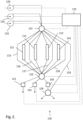
- the method can e.g. be carried out in a chromatography system 10 as illustrated in Fig. 1 .
- a chromatography system 10 as illustrated in Fig. 1 .
- Such a system comprises a plurality of chromatography columns 11,12,13 (three columns are shown in Fig. 1 but four or more columns are equally possible).
- the system can suitably be arranged for performing continuous chromatography.
- the columns may be packed with the same separation matrix and connected with one or more connecting lines 14,15,16 such that liquid can flow from one column 11 , 12 to a subsequent one 12 , 13 and from a last column 13 to a first column 11 and each connecting line between two columns may comprise at least one on/off valve 17 , 18 , 19 , which may be three-way or four-way valves.
- valves in conjunction with valves/valve blocks 23 , 25 , 29 also allow parallel operations of the columns, e.g. elution of one or more columns simultaneously with the loading of one or more other columns.
- the system may further comprise a feed pump 20 , e.g. connected via a first detector 21 to a first valve block 22 and one or more buffer pumps 34 , 35 , e.g. connected to valve block 22 .
- the first valve block 22 can further be connected to the inlet of a first column 11 via a first valve 23 .
- An outlet end of the first column 11 may be connected to a second valve 17 through a second detector 24 .
- the first valve block 22 can further be connected to the inlet of a second column 12 via a second valve or valve block 25 .
- An outlet end of the second column 12 can be connected to valve 18 via a third detector 26 .
- a valve 27 can be connected between valve 17 and valve 18 .
- Valve 27 can also be connected to a valve 28 which is also connected to valve 23 and the second valve block 25 .
- the effluent from the first column 11 can be directed to the inlet of the second column 12 through connecting line 14 , valves 17 , 27 , 28 and 25 .
- the first valve block 22 can be connected to the inlet of a third column 13 via valve 29 .
- An outlet end of the third column 13 may be connected to valve 19 via a fourth detector 30 .
- valve 31 can be connected between valve 18 and valve 19 .
- Valve 31 can also be connected to valve 32 which may also be connected to the second valve block 25 and valve 29 .
- the effluent from the second column 12 can be directed to the inlet of the third column 13 through connecting line 15 .
- the effluent from the third column 13 can be directed to the inlet of the first column 11 through connecting line 16 via valves 19 and 23 (alternatively it can be directed to a subsequent fourth column).
- the first, second, third and fourth detectors 21 , 24 , 26 , 30 may all be connected to a determining unit 37 .
- the determining unit can be adapted to use the detected signals from the detectors to determine breakthrough and saturation points for the three different columns.
- the determining unit 37 and all the valve blocks, valves and pumps may further be connected to a control unit 33 (all the connections are not shown in Fig. 1 ) which is adapted to control the chromatography system in terms of when to remove or add columns from/into the loading zone, change flow rates, start new elution steps, etc.
- the detectors 21 , 24 , 26 , 30 can e.g. be UV detectors.
- the control unit 33 may be configured to control the system according to breakthrough data obtained from the determining unit 37 . Alternatively, control unit 33 can use fixed predetermined step times for the switching operations.
- Fig. 2 illustrates an alternative chromatography system 110 for carrying out the method of the invention.
- the system comprises a plurality of chromatography columns (e.g. three or four columns) 111 , 112 , 113 , 114 , which may be packed with the same separation matrix.
- the columns are independently connectable to a feed pump 120 , buffer pumps 134 , 135 and/or connecting lines 115 , 116 , 117 , 118 , 119 via a multifunctional first valve block 122 . They are also independently connectable to the connecting lines and to the detectors 121 , 124 , 126 via multifunctional second valve block 125 .
- Valve blocks 122 and 125 allow the parallel coupling of several different flowpaths within the blocks (see e.g.
- WO2015094095 or WO2015094096 for useful designs of valves/valve blocks). They can also be used to connect one or more of the pumps with one or more of the connecting lines for bypassing or backflushing one or more of the columns.
- a further valve or valve block 129 allows the direction of a flow from detector 126 to either one or more collection vessels, waste or to connection line 119 for e.g. application on another column.
- Valves/valve blocks 122 , 125 , 129 , detectors 121 , 124 , 126 and pumps 120 , 134 , 135 are electrically or electromagnetically connected to a combined determining unit and control unit 133 for detection and for control of the flows.
- System 110 is similar to the commercially available ⁇ KTA TM pcc 75 system (GE Healthcare Life Sciences), with some minor modifications, e.g. the three pumps being directly connectable to three different columns. Both systems 10 and 110 may of course be further modified, e.g. by adding further columns, pumps, valves and/or detectors.
- the separation matrix particles can suitably be gel filtration particles having an exclusion limit for dextrans of less than 5000 kDa, such as of 500 kDa-5000 kDa or 500-3000 kDa.
- These particles enable the separation of a plasmid, which can often be in the size range of 2-20 kb (2-7 kb for vaccine-type plasmids and up to 20 kb for plasmids to be used in gene therapy), from lower molecular weight contaminants such as the more or less degraded RNA present in cell lysates, typically having a size of ⁇ 1 kb.
- the separation matrix particles may comprise a crosslinked polysaccharide, such as crosslinked agarose or alternatively crosslinked agar, cellulose or dextran.
- a crosslinked polysaccharide such as crosslinked agarose or alternatively crosslinked agar, cellulose or dextran.
- crosslinked agarose particles can e.g. be Sepharose TM 6 Fast Flow beads (GE Healthcare Life Sciences) with a dextran exclusion limit of 2000 kDa, average particle diameter 90 ⁇ m and particle diameter range 45-165 ⁇ m.
- Sepharose CL-6B crosslinked agarose beads GE Healthcare Life Sciences
- dextran exclusion limit approx. 1000 kDa may be used, although Sepharose 6 Fast Flow will allow higher flow rates due to its higher rigidity.
- highly rigid crosslinked agarose beads may be used, e.g. beads as described in US6602990 .
- the eluent (and optionally a further eluent) comprises at least 1.5 M of a salt, such as 1.5-2.5 M or 1.8-2.3 M salt.
- the total salt concentration of the eluent (and optionally the further eluent) may be at least 1.5 M, such as 1.5-2.5 M or 1.8-2.3 M.
- the salt may e.g. be ammonium sulfate and the eluent/further eluent may e.g. comprise at least 1.5 M ammonium sulfate, such as 1.5-2.5 or 1.8-2.3 M ammonium sulfate.
- the presence of the salt/ammonium sulfate improves the separation between the plasmid and the RNA contaminants.
- the process feed may comprise a clarified cell lysate, such as a lysate of gram negative cells, e.g. E. coli.
- the method comprises, before the separation, a step 0) of preparing a clarified cell lysate as the process feed.
- Step 0) may comprise contacting cells, such as E. coli cells, with alkali and a surfactant, such as SDS, to induce lysis and neutralizing e.g. with potassium acetate.
- This is a well-known method, involving the addition of NaOH and SDS to final concentrations of e.g. 0.1 M and 0.05% (see e.g.
- Step 0) may also be carried out in a continuous mode, e.g. by adding the lysis reagents in a static mixer or similar (see e.g. US2007/0213289 ).
- the clarification can be done by traditional filtration, but to avoid excessive clogging of filters, it can be advantageous to remove the bulk of the particulates by flocculation/flotation before a final filtration.
- This can be achieved by adding a hydrogen carbonate, e.g. ammonium hydrogen carbonate, to the crude neutralised lysate at a pH around 5, such as at pH 4-6 or 4.5-5.5. If the pH is outside this interval, it may be adjusted after the hydrogen carbonate addition so as to fall within the interval.
- the carbon dioxide bubbles generated under these conditions will cause flotation of flocculated particulates to the surface, leaving an almost totally clarified lysate as the bulk liquid.
- Such a flotation process can also be performed continuously, e.g. by flowing the lysate through a flotation vessel where the flotated material on the surface is scraped off or otherwise diverted, while the clarified lysate is passed through a filter without any clogging issues.
- the method may further comprise, after the separation, a step e) of purifying the recovered plasmid.
- a step e) of purifying the recovered plasmid This can be done e.g. by bind-elute chromatography and may suitably involve separating the desired super-coiled (sc) plasmid from open circle (oc) and other conformations of the plasmid.
- sc super-coiled
- oc open circle
- Both thiophilic and hydrophobic interaction chromatography methods can be used for this purpose.
- resins like PlasmidSelect TM or PlasmidSelect Xtra (GE Healthcare Life Sciences) may be used, while various chromatographic resins with e.g.
- Step e) can also be performed in a continuous mode, e.g. by using PCC or SMB continuous chromatography techniques. This can be achieved by the direct application of eluate from the steps above to a second multicolumn chromatography system.
- some columns may be used for the initial separation and some columns may be used for the further purification.
- the system may comprise both columns packed with gel filtration resin and columns packed with e.g. thiophilic or hydrophobic interaction resin.
- the flow rates were increased in comparison with run 1. As shown in Fig. 6 , the shape of the plasmid peak is still similar to run 1.
- the plasmid peak has a volume of 7.7 ml, corresponding to 0.39 column volumes, which indicates a certain degree of dilution.
- a periodic countercurrent chromatography (PCC) setup with four columns of the same type as used in Example 1 was arranged in the ⁇ KTA pcc 75 chromatography system.
- the sample and the buffers were the same as in Example 1, although the equilibration step was only performed once for all the columns before starting the PCC cycles.
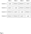
- Fig. 4 shows an overview of the different columns during the process.
- the loading step two serially coupled columns were used so that the outflow from the first loading column (Load 1) was directed to a second loading column (Load 2), The effect of the Load 2 step was primarily to wash the second column with the buffer flowing out from the first column.
- the duration of the Elution 2 step was longer than for the other steps, necessitating some waiting time in the other steps.
- the results are shown in Figs 8 and 9 , demonstrating a fully continuous separation.
- the electrophoresis gel in Fig. 10 shows an essentially complete removal of the low Mw RNA band from the high Mw plasmid.
- a simple way of expressing the productivity is to calculate the number of column volumes (CV) loaded per hour.
- CV column volumes
- the column can be loaded every 12 min, i.e. the productivity is 1.5 CV/h.
- PCC run 2 0.18 CV can be loaded every 4.2 min, corresponding to a productivity of 2.6 CV/h, i.e. a 170% improvement over Run 2 and 370% over Run 1.
- a continuous three-column setup can be expected to give even higher productivities.
Description
- The present invention relates to separation processes in the manufacturing of biopharmaceuticals, and more particularly to a separation process useful for separation of large species such as plasmids, virus particles etc.
- In the manufacturing of biopharmaceuticals such as vaccines, antibodies, recombinant proteins, gene therapy vectors etc. several chromatographic separation steps are usually needed to remove various contaminants and impurities from the product. These separation steps add significant cost and process time and there is hence a significant interest in intensifying them.
- Multicolumn continuous chromatography processes are available, where the feed is applied to a first column and is then diverted to one or more subsequent columns as the first columns approaches saturation and the first column is eluted and regenerated to be loaded again during elution and regeneration of the subsequent column(s). Such processes can be denoted periodic countercurrent chromatography (PCC) or simulated moving bed (SMB) and are of considerable interest for separation of biopharmaceuticals, see e.g.
US7901581 ,US20130248451 ,US20130280788 andUS7220356 . - PCC/SMB processes can significantly increase the productivity, but the increases achieved can depend quite strongly on the design of the process.
- Plasmids are of interest in the biopharmaceutical area primarily as vectors for gene therapies and certain cell therapies (e.g. for preparing CAR-T cells) but also in vaccine technology. The plasmids are large ring-shaped DNA molecules of bacterial origin, which present particular issues in chromatographic processes as their size prevents them from entering the pores of most chromatography media. A common first step in plasmid purification is a so-called group separation, where the plasmid preparation is applied to a gel filtration resin and the plasmid is recovered in the void fraction or a slightly retained fraction, while RNA, a major contaminant, enters the pores of the resin and is significantly retained. As with other gel filtration processes, this is a slow process with limited loading capacity and it would be highly interesting to speed it up by applying continuous processing.
- Accordingly, there is a need for new group separation processes for plasmids and other large species, such as e.g. virus particles, allowing an increased efficiency of the processes.
- One aspect of the invention is to provide an efficient method for continuously separating a plasmid or e.g. a virus particle or other large species. This is achieved with a method of applying a process feed containing a plasmid/virus particle or other large species to an apparatus with at least three chromatography columns packed with separation matrix particles, wherein while one chromatography column is loaded with the process feed, another chromatography column is eluted with an eluent to recover the separated plasmid, and yet another chromatography column is eluted with a further eluent to remove contaminants.
- Further suitable embodiments of the invention are described in the dependent claims.
-
-
Fig. 1 shows an example of a chromatography system that can be used with the method of the invention. -
Fig. 2 shows another example of a chromatography system that can be used with the method of the invention. -
Fig. 3 shows an example of the method of the invention using three columns. -
Fig. 4 shows an example of the method of the invention using four columns. -
Fig. 5 shows results from the single-column run 1 of Example 1. -
Fig. 6 shows results from the single-column run 2 of Example 1. -
Fig. 7 shows results from the four-column PCC run 1 of Example 2. -
Fig. 8 shows results from the four-column PCC run 2 of Example 2. -
Fig. 9 shows results (enlargement) from the four-column PCC run 2 of Example 2. -
Fig. 10 shows an electrophoresis gel with 1 Mw markers, 2 the sample and 3 the plasmid fraction. - In one aspect, the present invention discloses a method of continuous separation of a plasmid from a process feed comprising a plasmid in an apparatus with at least three chromatography columns. The method can also be used for other separations of large species, e.g. viruses, virus-like particles, antigen conjugates etc., from lower molecular-weight contaminants. The columns are packed with separation matrix particles, and while one chromatography column is loaded with the process feed, another chromatography column is eluted with an eluent to recover the separated plasmid, and yet another chromatography column is eluted with a further eluent (which can be the same eluent as used for eluting the plasmid) to remove contaminants such as RNA. It can be advantageous if the flow rates in the different steps are matched, so that no standstill is required in any step to wait for another step to finish.
- The method may in some embodiments, as illustrated by
Fig. 3 , comprise the steps of: - a) conveying a process feed comprising a plasmid through a first chromatography column comprising a packed bed of separation matrix particles;
- b) conveying an eluent through the first chromatography column, recovering the eluent with the plasmid after passage of the first chromatography column; and conveying the process feed through a second chromatography column packed with the same separation matrix as the first chromatography column; and
- c) conveying a further eluent (which can be the same eluent as in step b) through the first chromatography column; conveying an eluent through the second chromatography column, recovering the eluent with the plasmid after passage of the second chromatography column; and conveying the process feed through a third chromatography column packed with the same separation matrix as the first and second chromatography columns.
- After step c), steps a)-c) may repeated for the duration of the continuous process, e.g. until the entire process feed has been processed. In these repetitions step a) may further comprise conveying a further eluent through the second chromatography column while conveying an eluent through the third chromatography column and recovering the eluent with the plasmid after passage of the third chromatography column; and step b) may further comprise conveying a further eluent through the third chromatography column. Suitably, a process feed or eluent is conveyed through all three columns throughout all of steps a)-c), i.e. no flows are stopped to wait for another column/step to finish.
- In certain embodiments, as illustrated by
Fig. 4 , the method comprises the steps of: - a) conveying a process feed comprising a plasmid through a first chromatography column comprising a packed bed of separation matrix particles, and conveying an outflow from the first chromatography column through a second chromatography column packed with the same separation matrix as the first column;
- b) conveying an eluent through the first chromatography column, recovering the eluent with the plasmid after passage of the first chromatography column; and conveying the process feed through the second chromatography column and further through a third chromatography column packed with the same separation matrix as the first and second columns;
- c) conveying a further eluent through the first chromatography column; conveying an eluent through the second chromatography column, recovering the eluent with the plasmid after passage of the second chromatography column; and conveying the process feed through the third chromatography column and further through a fourth chromatography column packed with the same separation matrix as the first, second and third columns; and
- d) conveying a process feed comprising a plasmid through the fourth chromatography column and conveying an outflow from the fourth chromatography column through the first chromatography column; conveying a further eluent through the second chromatography column; and conveying an eluent through the third chromatography column, recovering the eluent with the plasmid after passage of the third chromatography column.
- After step d), steps a)-d) may be repeated for the duration of the continuous process, e.g. until the entire process feed has been processed. In these repetitions, step a) may further comprise conveying a further eluent through the third chromatography column and conveying an eluent through the fourth chromatography column while recovering the eluent with the plasmid after passage of the fourth chromatography column; and step b) may further comprises conveying a further eluent through the fourth chromatography column. Suitably, a process feed or eluent is conveyed through all three columns throughout all of steps a)-d), i.e. no flows are stopped to wait for another column/step to finish.
- The method can e.g. be carried out in a
chromatography system 10 as illustrated inFig. 1 . Such a system comprises a plurality ofchromatography columns Fig. 1 but four or more columns are equally possible). The system can suitably be arranged for performing continuous chromatography. The columns may be packed with the same separation matrix and connected with one or more connectinglines column last column 13 to afirst column 11 and each connecting line between two columns may comprise at least one on/offvalve valve blocks feed pump 20, e.g. connected via afirst detector 21 to afirst valve block 22 and one ormore buffer pumps valve block 22. Thefirst valve block 22 can further be connected to the inlet of afirst column 11 via afirst valve 23. An outlet end of thefirst column 11 may be connected to asecond valve 17 through asecond detector 24. Thefirst valve block 22 can further be connected to the inlet of asecond column 12 via a second valve orvalve block 25. An outlet end of thesecond column 12 can be connected tovalve 18 via athird detector 26. Furthermore, avalve 27 can be connected betweenvalve 17 andvalve 18. Valve 27 can also be connected to avalve 28 which is also connected tovalve 23 and thesecond valve block 25. Hereby the effluent from thefirst column 11 can be directed to the inlet of thesecond column 12 through connectingline 14,valves first valve block 22 can be connected to the inlet of athird column 13 viavalve 29. An outlet end of thethird column 13 may be connected tovalve 19 via afourth detector 30. Furthermorevalve 31 can be connected betweenvalve 18 andvalve 19. Valve 31 can also be connected tovalve 32 which may also be connected to thesecond valve block 25 andvalve 29. Hereby the effluent from thesecond column 12 can be directed to the inlet of thethird column 13 through connectingline 15. The effluent from thethird column 13 can be directed to the inlet of thefirst column 11 through connectingline 16 viavalves 19 and 23 (alternatively it can be directed to a subsequent fourth column). Furthermore, the first, second, third andfourth detectors unit 37. The determining unit can be adapted to use the detected signals from the detectors to determine breakthrough and saturation points for the three different columns. The determiningunit 37 and all the valve blocks, valves and pumps may further be connected to a control unit 33 (all the connections are not shown inFig. 1 ) which is adapted to control the chromatography system in terms of when to remove or add columns from/into the loading zone, change flow rates, start new elution steps, etc. Thedetectors control unit 33 may be configured to control the system according to breakthrough data obtained from the determiningunit 37. Alternatively,control unit 33 can use fixed predetermined step times for the switching operations. -
Fig. 2 illustrates an alternative chromatography system 110 for carrying out the method of the invention. The system comprises a plurality of chromatography columns (e.g. three or four columns) 111,112,113,114, which may be packed with the same separation matrix. The columns are independently connectable to afeed pump 120, buffer pumps 134, 135 and/or connectinglines first valve block 122. They are also independently connectable to the connecting lines and to thedetectors second valve block 125. Valve blocks 122 and 125 allow the parallel coupling of several different flowpaths within the blocks (see e.g.WO2015094095 orWO2015094096 for useful designs of valves/valve blocks). They can also be used to connect one or more of the pumps with one or more of the connecting lines for bypassing or backflushing one or more of the columns. A further valve orvalve block 129 allows the direction of a flow fromdetector 126 to either one or more collection vessels, waste or toconnection line 119 for e.g. application on another column. Valves/valve blocks 122,125,129,detectors control unit 133 for detection and for control of the flows. System 110 is similar to the commercially available ÄKTA™ pcc 75 system (GE Healthcare Life Sciences), with some minor modifications, e.g. the three pumps being directly connectable to three different columns. Bothsystems 10 and 110 may of course be further modified, e.g. by adding further columns, pumps, valves and/or detectors. - In the embodiments discussed above, the separation matrix particles can suitably be gel filtration particles having an exclusion limit for dextrans of less than 5000 kDa, such as of 500 kDa-5000 kDa or 500-3000 kDa. These particles enable the separation of a plasmid, which can often be in the size range of 2-20 kb (2-7 kb for vaccine-type plasmids and up to 20 kb for plasmids to be used in gene therapy), from lower molecular weight contaminants such as the more or less degraded RNA present in cell lysates, typically having a size of < 1 kb. The separation matrix particles may comprise a crosslinked polysaccharide, such as crosslinked agarose or alternatively crosslinked agar, cellulose or dextran. An example of crosslinked agarose particles can e.g. be Sepharose™ 6 Fast Flow beads (GE Healthcare Life Sciences) with a dextran exclusion limit of 2000 kDa, average particle diameter 90 µm and particle diameter range 45-165 µm. Alternatively, Sepharose CL-6B crosslinked agarose beads (GE Healthcare Life Sciences) with dextran exclusion limit approx. 1000 kDa may be used, although
Sepharose 6 Fast Flow will allow higher flow rates due to its higher rigidity. To allow even higher flow rates, highly rigid crosslinked agarose beads may be used, e.g. beads as described inUS6602990 . - In some embodiments, the eluent (and optionally a further eluent) comprises at least 1.5 M of a salt, such as 1.5-2.5 M or 1.8-2.3 M salt. Alternatively expressed, the total salt concentration of the eluent (and optionally the further eluent) may be at least 1.5 M, such as 1.5-2.5 M or 1.8-2.3 M. The salt may e.g. be ammonium sulfate and the eluent/further eluent may e.g. comprise at least 1.5 M ammonium sulfate, such as 1.5-2.5 or 1.8-2.3 M ammonium sulfate. The presence of the salt/ammonium sulfate improves the separation between the plasmid and the RNA contaminants.
- The process feed may comprise a clarified cell lysate, such as a lysate of gram negative cells, e.g. E. coli. In some embodiments, the method comprises, before the separation, a step 0) of preparing a clarified cell lysate as the process feed. Step 0) may comprise contacting cells, such as E. coli cells, with alkali and a surfactant, such as SDS, to induce lysis and neutralizing e.g. with potassium acetate. This is a well-known method, involving the addition of NaOH and SDS to final concentrations of e.g. 0.1 M and 0.05% (see e.g. L A Ciccolini et al: Biotech Bioeng 87, 293-302 (2004)). Step 0) may also be carried out in a continuous mode, e.g. by adding the lysis reagents in a static mixer or similar (see e.g.
US2007/0213289 ). - The clarification can be done by traditional filtration, but to avoid excessive clogging of filters, it can be advantageous to remove the bulk of the particulates by flocculation/flotation before a final filtration. This can be achieved by adding a hydrogen carbonate, e.g. ammonium hydrogen carbonate, to the crude neutralised lysate at a pH around 5, such as at pH 4-6 or 4.5-5.5. If the pH is outside this interval, it may be adjusted after the hydrogen carbonate addition so as to fall within the interval. The carbon dioxide bubbles generated under these conditions will cause flotation of flocculated particulates to the surface, leaving an almost totally clarified lysate as the bulk liquid. Such a flotation process can also be performed continuously, e.g. by flowing the lysate through a flotation vessel where the flotated material on the surface is scraped off or otherwise diverted, while the clarified lysate is passed through a filter without any clogging issues.
- In addition to the steps discussed above, the method may further comprise, after the separation, a step e) of purifying the recovered plasmid. This can be done e.g. by bind-elute chromatography and may suitably involve separating the desired super-coiled (sc) plasmid from open circle (oc) and other conformations of the plasmid. Both thiophilic and hydrophobic interaction chromatography methods can be used for this purpose. For thiophilic chromatography, resins like PlasmidSelect™ or PlasmidSelect Xtra (GE Healthcare Life Sciences) may be used, while various chromatographic resins with e.g. phenyl, butyl or hexyl groups have been suggested for hydrophobic interaction chromatography of plasmids (see e.g.
US2007/0213289 ). Step e) can also be performed in a continuous mode, e.g. by using PCC or SMB continuous chromatography techniques. This can be achieved by the direct application of eluate from the steps above to a second multicolumn chromatography system. Alternatively, in a system with several chromatography columns, some columns may be used for the initial separation and some columns may be used for the further purification. In this case, the system may comprise both columns packed with gel filtration resin and columns packed with e.g. thiophilic or hydrophobic interaction resin. -
- Sample: E. coli clarified lysate, containing plasmid pJV4 (6 kb), 17 mM Tris, 3.3 mM EDTA, 1 M potassium acetate.
- Column: 20 ml Sepharose 6 Fast Flow (Sepharose 6FF) gel filtration resin (GE Healthcare Life Sciences) packed in a
HiPrep ™ 16/10 column (GE Healthcare Life Sciences), with 16 mm bed diameter and 100 mm bed height. - Chromatography system: ÄKTA pcc 75 system (GE Healthcare Life Sciences)
- Equilibration buffer: 2.1 M ammonium sulfate, 10 mM EDTA, 100 mM Tris-HCl pH 7.5. Elution buffer: 2.1 M ammonium sulfate, 10 mM EDTA, 100 mM Tris-HCl pH 7.5.
-
Table 1. Conditions for run 1.Step Buffer Column volumes Flow rate (ml/min) Flow velocity (cm/h) Residence time (min) Equilibration Equilibration buffer 5 1.67 50 12 Load Sample 0.3 1.67 50 12 Elution Elution buffer 1 3 1.67 50 12 - This was the initial run, for checking the separation pattern and starting optimisation. The results are shown in
Fig. 5 and indicate a clear separation between the plasmid (the first peak) and contaminant RNA (the second peak). -
Table 2. Conditions for run 2.Step Buffer Column volumes Flow rate (ml/min) Flow velocity (cm/h) Residence time (min) Equilibration Equilibration buffer 2 3.0 90 6.7 Load Sample 0.3 3.0 90 6.7 Elution Elution buffer 1 3 3.0 90 6.7 - The flow rates were increased in comparison with
run 1. As shown inFig. 6 , the shape of the plasmid peak is still similar to run 1. The plasmid peak has a volume of 7.7 ml, corresponding to 0.39 column volumes, which indicates a certain degree of dilution. - A periodic countercurrent chromatography (PCC) setup with four columns of the same type as used in Example 1 was arranged in the ÄKTA pcc 75 chromatography system. The sample and the buffers were the same as in Example 1, although the equilibration step was only performed once for all the columns before starting the PCC cycles.
Fig. 4 shows an overview of the different columns during the process. For the loading step, two serially coupled columns were used so that the outflow from the first loading column (Load 1) was directed to a second loading column (Load 2), The effect of theLoad 2 step was primarily to wash the second column with the buffer flowing out from the first column. InPCC run 1, the duration of theElution 2 step was longer than for the other steps, necessitating some waiting time in the other steps. -
Table 3. Conditions for PCC run 1Step Buffer Column volumes Flow rate (ml/min) Flow velocity (cm/h) Residence time (min) Equilibration Equilibration buffer 4 5.0 150 4 Load Sample 0.2 1.8 54 11 Elution 1Elution buffer 0.36 1.8 54 11 Elution 2Elution buffer 1 5.0 150 4 - The results, as shown in
Fig. 7 , indicate a reasonably good performance, although with some UV breakthrough already during loading, indicating that some plasmid is eluted directly in the flowthrough. - In this experiment, the amount loaded was slightly reduced to avoid elution in the flowthrough. Further, the step times were adjusted so that all steps could be run continuously without any waiting times. As above, the equilibration step was only run once, before the actual PCC cycles.
Table 4. Conditions for PCC run 2Step Buffer Column volumes Flow rate (ml/min) Flow velocity (cm/h) Residence time (min) Equilibration Equilibration buffer 4 5.0 150 4 Load Sample 0.18 0.9 27 22 Elution 1Elution buffer 0.36 1.8 54 11 Elution 2Elution buffer 1 5.0 150 4 - The results are shown in
Figs 8 and9 , demonstrating a fully continuous separation. The electrophoresis gel inFig. 10 shows an essentially complete removal of the low Mw RNA band from the high Mw plasmid. A simple way of expressing the productivity is to calculate the number of column volumes (CV) loaded per hour. For the single column batch experiments, at 1.67 ml/min (Run 1), loading is possible every 25 min, leading to a productivity of 0.7 CV/h. At 3.0 ml/min, the column can be loaded every 12 min, i.e. the productivity is 1.5 CV/h. In the optimised PCC example (PCC run 2), 0.18 CV can be loaded every 4.2 min, corresponding to a productivity of 2.6 CV/h, i.e. a 170% improvement overRun 2 and 370% overRun 1. A continuous three-column setup can be expected to give even higher productivities.
Claims (15)
- A method of continuous separation of a plasmid from a process feed comprising a plasmid in an apparatus with at least three chromatography columns packed with particles of the same separation matrix, wherein while one chromatography column is loaded with the process feed, another chromatography column is eluted with an eluent to recover the separated plasmid, and yet another chromatography column is eluted with a further eluent to remove contaminants.
- The method of claim 1, comprising the successive steps of:a) conveying a process feed comprising a plasmid through a first chromatography column comprising a packed bed of separation matrix particles;b) conveying an eluent through said first chromatography column, recovering the eluent with the plasmid after passage of the first chromatography column; and conveying said process feed through a second chromatography column packed with the same separation matrix as the first chromatography column; andc) conveying a further eluent through said first chromatography column; conveying an eluent through said second chromatography column, recovering the eluent with the plasmid after passage of the second chromatography column; and conveying said process feed through a third chromatography column packed with the same separation matrix as the first and second chromatography columns.
- The method of claim 2, wherein after step c), steps a)-c) are repeated for the duration of the continuous process, and wherein optionally in the repetitions:step a) further comprises conveying a further eluent through said second chromatography column while conveying an eluent through said third chromatography column and recovering the eluent with the plasmid after passage of the third chromatography column; andstep b) further comprises conveying a further eluent through said third chromatography column.
- The method of any one of claims 2-3, wherein a process feed or eluent is conveyed through all three columns throughout all of steps a)-c).
- The method of claim 1, comprising the successive steps of:a) conveying a process feed comprising a plasmid through a first chromatography column comprising a packed bed of separation matrix particles, and conveying an outflow from said first chromatography column through a second chromatography column packed with the same separation matrix as the first column;b) conveying an eluent through said first chromatography column, recovering the eluent with the plasmid after passage of the first chromatography column; and conveying said process feed through said second chromatography column and further through a third chromatography column packed with the same separation matrix as the first and second columns;c) conveying a further eluent through said first chromatography column; conveying an eluent through said second chromatography column, recovering the eluent with the plasmid after passage of the second chromatography column; and conveying said process feed through said third chromatography column and further through a fourth chromatography column packed with the same separation matrix as the first, second and third columns; andd) conveying a process feed comprising a plasmid through said fourth chromatography column and conveying an outflow from said fourth chromatography column through said first chromatography column; conveying a further eluent through said second chromatography column; and conveying an eluent through said third chromatography column, recovering the eluent with the plasmid after passage of the third chromatography column.
- The method of claim 5, wherein after step d), steps a)-d) are repeated for the duration of the continuous process, and wherein optionally in the repetitions:step a) further comprises conveying a further eluent through said third chromatography column and conveying an eluent through said fourth chromatography column while recovering the eluent with the plasmid after passage of the fourth chromatography column; andstep b) further comprises conveying a further eluent through said fourth chromatography column.
- The method of any one of claims 5-6, wherein a process feed or eluent is conveyed through all three columns throughout all of steps a)-d).
- The method of any preceding claim, wherein said separation matrix particles are gel filtration particles having an exclusion limit for dextrans of less than 5000 kDa, such as of 500 kDa-5000 kDa or 500-3000 kDa.
- The method of any preceding claim, wherein said separation matrix particles comprise a crosslinked polysaccharide, such as crosslinked agarose.
- The method of any preceding claim, wherein:a) said eluent comprises at least 1.5 M of a salt, such as 1.5-2.5 or 1.8-2.3 M salt;b) the total salt concentration of said eluent is at least 1.5 M, such as 1.5-2.5 or 1.8-2.3 M; and/orc) said eluent comprises at least 1.5 M ammonium sulfate, such as 1.5-2.5 or 1.8-2.3 M ammonium sulfate.
- The method of any preceding claim, wherein said process feed comprises a clarified cell lysate.
- The method of any preceding claim, comprising, before the separation, a step 0) of preparing a clarified cell lysate as the process feed, wherein step 0) optionally comprises contacting cells, such as E. coli cells, with alkali and a surfactant, such as SDS and, further optionally is carried out in a continuous mode.
- The method of claim 12, wherein step 0) further comprises the addition of a hydrogen carbonate salt, such as ammonium hydrogen carbonate, optionally followed by adjustment of pH to 4-6.
- The method of any preceding claim, further comprising, after the separation, a step e) of purifying the recovered plasmid, which optionally comprises bind-elute chromatography, such as thiophilic or hydrophobic interaction chromatography.
- The method of claim 14, wherein step e) is operated in a continuous mode.
Applications Claiming Priority (2)
| Application Number | Priority Date | Filing Date | Title |
|---|---|---|---|
| GBGB1710130.4A GB201710130D0 (en) | 2017-06-26 | 2017-06-26 | A Method of seperation |
| PCT/EP2018/054478 WO2019001778A1 (en) | 2017-06-26 | 2018-02-23 | Periodic countercurrent chromatography separation of plasmids |
Publications (2)
| Publication Number | Publication Date |
|---|---|
| EP3645139A1 EP3645139A1 (en) | 2020-05-06 |
| EP3645139B1 true EP3645139B1 (en) | 2023-07-26 |
Family
ID=59523684
Family Applications (1)
| Application Number | Title | Priority Date | Filing Date |
|---|---|---|---|
| EP18711827.8A Active EP3645139B1 (en) | 2017-06-26 | 2018-02-23 | Periodic countercurrent chromatography separation of plasmids |
Country Status (6)
| Country | Link |
|---|---|
| US (1) | US20200141912A1 (en) |
| EP (1) | EP3645139B1 (en) |
| CN (1) | CN110769909B (en) |
| ES (1) | ES2953488T3 (en) |
| GB (1) | GB201710130D0 (en) |
| WO (1) | WO2019001778A1 (en) |
Families Citing this family (3)
| Publication number | Priority date | Publication date | Assignee | Title |
|---|---|---|---|---|
| AU2019398097A1 (en) | 2018-12-13 | 2021-07-29 | Paragon 28, Inc. | Trial insert assembly |
| CN114072217A (en) * | 2019-06-28 | 2022-02-18 | 信达生物制药(苏州)有限公司 | Combined chromatography device, seamless connection chromatography method and biological agent purification method |
| JP2024509878A (en) * | 2021-03-10 | 2024-03-05 | アムジエン・インコーポレーテツド | Parallel chromatography system and method |
Family Cites Families (15)
| Publication number | Priority date | Publication date | Assignee | Title |
|---|---|---|---|---|
| SE9601368D0 (en) | 1996-04-11 | 1996-04-11 | Pharmacia Biotech Ab | Process for the production of a porous cross-linked polysaccharide gel |
| JPH1190106A (en) * | 1997-09-26 | 1999-04-06 | Daicel Chem Ind Ltd | Pseudo moving bed type chromatographic separating device |
| US20020104801A1 (en) * | 1998-04-06 | 2002-08-08 | Nicolas Voute | Small dense microporous solid support materials, their preparation,and use for purification of large macromolecules and bioparticles |
| US7108789B2 (en) * | 2002-07-29 | 2006-09-19 | Calgon Carbon Corporation | High performance continuous reaction/separation process using a continuous liquid-solid contactor |
| EP1545574B8 (en) | 2002-09-13 | 2014-09-24 | Biogen Idec Inc. | Method of purifying polypeptides by simulated moving bed chromatography |
| EA010576B1 (en) | 2004-04-19 | 2008-10-30 | Сентельон | Method for purifying plasmid dna |
| EP1716900A1 (en) * | 2005-04-29 | 2006-11-02 | Eidgenössische Technische Hochschule Zürich | Method and device for chromatographic purification |
| WO2008153472A1 (en) * | 2007-06-15 | 2008-12-18 | Ge Healthcare Bio-Sciences Ab | Chromatography method |
| FR2929533B1 (en) * | 2008-04-03 | 2010-04-30 | Novasep | MULTICOLOUR GRADIENT SEPARATION PROCESS. |
| US20130248451A1 (en) | 2010-12-03 | 2013-09-26 | Ge Healthcare Bio-Sciences Ab | System and process for biopolymer chromatography |
| EP2656892A1 (en) | 2012-04-23 | 2013-10-30 | Merck Patent GmbH | Chromatography method |
| US10309938B2 (en) | 2013-12-19 | 2019-06-04 | Ge Healthcare Bio-Sciences Ab | Rotary valve |
| JP6575946B2 (en) | 2013-12-19 | 2019-09-18 | ジーイー・ヘルスケア・バイオサイエンス・アクチボラグ | Rotary valve and chromatography system |
| JP6873528B2 (en) * | 2014-12-18 | 2021-05-19 | サイティバ・スウェーデン・アクチボラグ | Automated chromatography column switching control based on pressure detection |
| US11835501B2 (en) * | 2015-07-13 | 2023-12-05 | Sartorius Stedim Chromatography Systems Ltd. | Optimizing operating binding capacity for a multiple column chromatography process |
-
2017
- 2017-06-26 GB GBGB1710130.4A patent/GB201710130D0/en not_active Ceased
-
2018
- 2018-02-23 WO PCT/EP2018/054478 patent/WO2019001778A1/en unknown
- 2018-02-23 CN CN201880042678.2A patent/CN110769909B/en active Active
- 2018-02-23 US US16/622,467 patent/US20200141912A1/en active Pending
- 2018-02-23 ES ES18711827T patent/ES2953488T3/en active Active
- 2018-02-23 EP EP18711827.8A patent/EP3645139B1/en active Active
Also Published As
| Publication number | Publication date |
|---|---|
| CN110769909B (en) | 2023-06-20 |
| CN110769909A (en) | 2020-02-07 |
| GB201710130D0 (en) | 2017-08-09 |
| ES2953488T3 (en) | 2023-11-13 |
| US20200141912A1 (en) | 2020-05-07 |
| EP3645139A1 (en) | 2020-05-06 |
| WO2019001778A1 (en) | 2019-01-03 |
Similar Documents
| Publication | Publication Date | Title |
|---|---|---|
| Eon-Duval et al. | Purification of pharmaceutical-grade plasmid DNA by anion-exchange chromatography in an RNase-free process | |
| KR101790700B1 (en) | Methods for increasing the capacity of flow-through processes | |
| EP3645139B1 (en) | Periodic countercurrent chromatography separation of plasmids | |
| Urthaler et al. | Improved downstream process for the production of plasmid DNA for gene therapy | |
| US10859542B2 (en) | High efficiency continuous countercurrent tangential negative chromatography | |
| EP3663401B1 (en) | Purification process for biological molecules such as plasmid dna using anionic exchange chromatography | |
| EP3105580A1 (en) | Automated multi-step purification system | |
| Shinkazh et al. | Countercurrent tangential chromatography for large‐scale protein purification | |
| Urthaler et al. | Industrial scale cGMP purification of pharmaceutical grade plasmid‐DNA | |
| CN109030686A (en) | A kind of three-dimensional liquid chromatogram protein purification device and its application method | |
| CN106884011B (en) | Combined liquid chromatography separation method for large-scale plasmid purification | |
| Walch et al. | Continuous desalting of refolded protein solution improves capturing in ion exchange chromatography: A seamless process | |
| US11110374B2 (en) | Continuous countercurrent spiral chromatography | |
| Guerrero‐Germán et al. | Purification of plasmid DNA from Escherichia coli ferments using anion‐exchange membrane and hydrophobic chromatography | |
| EP4234695A1 (en) | Methods for the selective removal of contaminants during a process of purifying biologic agents | |
| May et al. | Improving process economy with expanded-bed adsorption technology | |
| JP6991312B2 (en) | An apparatus for continuously producing an antibody from a cell culture medium using a plurality of modules in which an in-line mixer and a hydrocyclone are integrated, and a method for producing an antibody using the apparatus. | |
| Erkal et al. | Monoklonal Antikor Üretimleri İçin Alt Akım Prosesleri | |
| Boulaisa et al. | Implementation of a process-scale adenovirus purification with a single-use platform | |
| Macdonald | Disrupting Downstream Bottlenecks | |
| Bates | Downstream processing | |
| KR20190076046A (en) | Desalting process of protein solution | |
| Kanani et al. | Salt-tolerant cation exchange HD-Sb hydrogel membrane: mAb purification performance in flowthrough mode | |
| Labant | Boosting Downstream Productivity |
Legal Events
| Date | Code | Title | Description |
|---|---|---|---|
| STAA | Information on the status of an ep patent application or granted ep patent |
Free format text: STATUS: UNKNOWN |
|
| STAA | Information on the status of an ep patent application or granted ep patent |
Free format text: STATUS: THE INTERNATIONAL PUBLICATION HAS BEEN MADE |
|
| PUAI | Public reference made under article 153(3) epc to a published international application that has entered the european phase |
Free format text: ORIGINAL CODE: 0009012 |
|
| STAA | Information on the status of an ep patent application or granted ep patent |
Free format text: STATUS: REQUEST FOR EXAMINATION WAS MADE |
|
| 17P | Request for examination filed |
Effective date: 20191211 |
|
| AK | Designated contracting states |
Kind code of ref document: A1 Designated state(s): AL AT BE BG CH CY CZ DE DK EE ES FI FR GB GR HR HU IE IS IT LI LT LU LV MC MK MT NL NO PL PT RO RS SE SI SK SM TR |
|
| AX | Request for extension of the european patent |
Extension state: BA ME |
|
| RAP1 | Party data changed (applicant data changed or rights of an application transferred) |
Owner name: CYTIVA BIOPROCESS R&D AB |
|
| DAV | Request for validation of the european patent (deleted) | ||
| DAX | Request for extension of the european patent (deleted) | ||
| GRAP | Despatch of communication of intention to grant a patent |
Free format text: ORIGINAL CODE: EPIDOSNIGR1 |
|
| STAA | Information on the status of an ep patent application or granted ep patent |
Free format text: STATUS: GRANT OF PATENT IS INTENDED |
|
| INTG | Intention to grant announced |
Effective date: 20230405 |
|
| GRAS | Grant fee paid |
Free format text: ORIGINAL CODE: EPIDOSNIGR3 |
|
| GRAA | (expected) grant |
Free format text: ORIGINAL CODE: 0009210 |
|
| STAA | Information on the status of an ep patent application or granted ep patent |
Free format text: STATUS: THE PATENT HAS BEEN GRANTED |
|
| P01 | Opt-out of the competence of the unified patent court (upc) registered |
Effective date: 20230526 |
|
| AK | Designated contracting states |
Kind code of ref document: B1 Designated state(s): AL AT BE BG CH CY CZ DE DK EE ES FI FR GB GR HR HU IE IS IT LI LT LU LV MC MK MT NL NO PL PT RO RS SE SI SK SM TR |
|
| REG | Reference to a national code |
Ref country code: CH Ref legal event code: EP |
|
| REG | Reference to a national code |
Ref country code: IE Ref legal event code: FG4D |
|
| REG | Reference to a national code |
Ref country code: DE Ref legal event code: R096 Ref document number: 602018054007 Country of ref document: DE |
|
| REG | Reference to a national code |
Ref country code: NL Ref legal event code: FP |
|
| REG | Reference to a national code |
Ref country code: LT Ref legal event code: MG9D |
|
| REG | Reference to a national code |
Ref country code: ES Ref legal event code: FG2A Ref document number: 2953488 Country of ref document: ES Kind code of ref document: T3 Effective date: 20231113 |
|
| PG25 | Lapsed in a contracting state [announced via postgrant information from national office to epo] |
Ref country code: GR Free format text: LAPSE BECAUSE OF FAILURE TO SUBMIT A TRANSLATION OF THE DESCRIPTION OR TO PAY THE FEE WITHIN THE PRESCRIBED TIME-LIMIT Effective date: 20231027 |
|
| PG25 | Lapsed in a contracting state [announced via postgrant information from national office to epo] |
Ref country code: SE Free format text: LAPSE BECAUSE OF FAILURE TO SUBMIT A TRANSLATION OF THE DESCRIPTION OR TO PAY THE FEE WITHIN THE PRESCRIBED TIME-LIMIT Effective date: 20230726 Ref country code: RS Free format text: LAPSE BECAUSE OF FAILURE TO SUBMIT A TRANSLATION OF THE DESCRIPTION OR TO PAY THE FEE WITHIN THE PRESCRIBED TIME-LIMIT Effective date: 20230726 Ref country code: PT Free format text: LAPSE BECAUSE OF FAILURE TO SUBMIT A TRANSLATION OF THE DESCRIPTION OR TO PAY THE FEE WITHIN THE PRESCRIBED TIME-LIMIT Effective date: 20231127 Ref country code: NO Free format text: LAPSE BECAUSE OF FAILURE TO SUBMIT A TRANSLATION OF THE DESCRIPTION OR TO PAY THE FEE WITHIN THE PRESCRIBED TIME-LIMIT Effective date: 20231026 Ref country code: LV Free format text: LAPSE BECAUSE OF FAILURE TO SUBMIT A TRANSLATION OF THE DESCRIPTION OR TO PAY THE FEE WITHIN THE PRESCRIBED TIME-LIMIT Effective date: 20230726 Ref country code: LT Free format text: LAPSE BECAUSE OF FAILURE TO SUBMIT A TRANSLATION OF THE DESCRIPTION OR TO PAY THE FEE WITHIN THE PRESCRIBED TIME-LIMIT Effective date: 20230726 Ref country code: HR Free format text: LAPSE BECAUSE OF FAILURE TO SUBMIT A TRANSLATION OF THE DESCRIPTION OR TO PAY THE FEE WITHIN THE PRESCRIBED TIME-LIMIT Effective date: 20230726 Ref country code: GR Free format text: LAPSE BECAUSE OF FAILURE TO SUBMIT A TRANSLATION OF THE DESCRIPTION OR TO PAY THE FEE WITHIN THE PRESCRIBED TIME-LIMIT Effective date: 20231027 Ref country code: FI Free format text: LAPSE BECAUSE OF FAILURE TO SUBMIT A TRANSLATION OF THE DESCRIPTION OR TO PAY THE FEE WITHIN THE PRESCRIBED TIME-LIMIT Effective date: 20230726 |
|
| PGFP | Annual fee paid to national office [announced via postgrant information from national office to epo] |
Ref country code: IE Payment date: 20231211 Year of fee payment: 7 |
|
| REG | Reference to a national code |
Ref country code: AT Ref legal event code: UEP Ref document number: 1591274 Country of ref document: AT Kind code of ref document: T Effective date: 20230726 |
|
| PG25 | Lapsed in a contracting state [announced via postgrant information from national office to epo] |
Ref country code: PL Free format text: LAPSE BECAUSE OF FAILURE TO SUBMIT A TRANSLATION OF THE DESCRIPTION OR TO PAY THE FEE WITHIN THE PRESCRIBED TIME-LIMIT Effective date: 20230726 |
|
| PGFP | Annual fee paid to national office [announced via postgrant information from national office to epo] |
Ref country code: NL Payment date: 20240108 Year of fee payment: 7 |
|
| PGFP | Annual fee paid to national office [announced via postgrant information from national office to epo] |
Ref country code: IS Payment date: 20240109 Year of fee payment: 7 |
|
| PGFP | Annual fee paid to national office [announced via postgrant information from national office to epo] |
Ref country code: ES Payment date: 20240306 Year of fee payment: 7 |