EP3644519A1 - Air conditioner current loop communication circuit and air conditioner - Google Patents
Air conditioner current loop communication circuit and air conditioner Download PDFInfo
- Publication number
- EP3644519A1 EP3644519A1 EP17920529.9A EP17920529A EP3644519A1 EP 3644519 A1 EP3644519 A1 EP 3644519A1 EP 17920529 A EP17920529 A EP 17920529A EP 3644519 A1 EP3644519 A1 EP 3644519A1
- Authority
- EP
- European Patent Office
- Prior art keywords
- current loop
- loop communication
- air conditioner
- power supply
- module
- Prior art date
- Legal status (The legal status is an assumption and is not a legal conclusion. Google has not performed a legal analysis and makes no representation as to the accuracy of the status listed.)
- Granted
Links
Images




Classifications
-
- F—MECHANICAL ENGINEERING; LIGHTING; HEATING; WEAPONS; BLASTING
- F24—HEATING; RANGES; VENTILATING
- F24F—AIR-CONDITIONING; AIR-HUMIDIFICATION; VENTILATION; USE OF AIR CURRENTS FOR SCREENING
- F24F11/00—Control or safety arrangements
- F24F11/88—Electrical aspects, e.g. circuits
-
- F—MECHANICAL ENGINEERING; LIGHTING; HEATING; WEAPONS; BLASTING
- F24—HEATING; RANGES; VENTILATING
- F24F—AIR-CONDITIONING; AIR-HUMIDIFICATION; VENTILATION; USE OF AIR CURRENTS FOR SCREENING
- F24F11/00—Control or safety arrangements
- F24F11/30—Control or safety arrangements for purposes related to the operation of the system, e.g. for safety or monitoring
- F24F11/46—Improving electric energy efficiency or saving
-
- G—PHYSICS
- G05—CONTROLLING; REGULATING
- G05B—CONTROL OR REGULATING SYSTEMS IN GENERAL; FUNCTIONAL ELEMENTS OF SUCH SYSTEMS; MONITORING OR TESTING ARRANGEMENTS FOR SUCH SYSTEMS OR ELEMENTS
- G05B19/00—Program-control systems
- G05B19/02—Program-control systems electric
- G05B19/04—Program control other than numerical control, i.e. in sequence controllers or logic controllers
- G05B19/042—Program control other than numerical control, i.e. in sequence controllers or logic controllers using digital processors
- G05B19/0428—Safety, monitoring
-
- H—ELECTRICITY
- H04—ELECTRIC COMMUNICATION TECHNIQUE
- H04B—TRANSMISSION
- H04B3/00—Line transmission systems
- H04B3/02—Details
-
- H—ELECTRICITY
- H04—ELECTRIC COMMUNICATION TECHNIQUE
- H04B—TRANSMISSION
- H04B3/00—Line transmission systems
- H04B3/54—Systems for transmission via power distribution lines
-
- G—PHYSICS
- G05—CONTROLLING; REGULATING
- G05B—CONTROL OR REGULATING SYSTEMS IN GENERAL; FUNCTIONAL ELEMENTS OF SUCH SYSTEMS; MONITORING OR TESTING ARRANGEMENTS FOR SUCH SYSTEMS OR ELEMENTS
- G05B2219/00—Program-control systems
- G05B2219/20—Pc systems
- G05B2219/25—Pc structure of the system
- G05B2219/25191—Current loop
-
- G—PHYSICS
- G05—CONTROLLING; REGULATING
- G05B—CONTROL OR REGULATING SYSTEMS IN GENERAL; FUNCTIONAL ELEMENTS OF SUCH SYSTEMS; MONITORING OR TESTING ARRANGEMENTS FOR SUCH SYSTEMS OR ELEMENTS
- G05B2219/00—Program-control systems
- G05B2219/20—Pc systems
- G05B2219/25—Pc structure of the system
- G05B2219/25257—Microcontroller
-
- G—PHYSICS
- G05—CONTROLLING; REGULATING
- G05B—CONTROL OR REGULATING SYSTEMS IN GENERAL; FUNCTIONAL ELEMENTS OF SUCH SYSTEMS; MONITORING OR TESTING ARRANGEMENTS FOR SUCH SYSTEMS OR ELEMENTS
- G05B2219/00—Program-control systems
- G05B2219/20—Pc systems
- G05B2219/26—Pc applications
- G05B2219/2638—Airconditioning
-
- H—ELECTRICITY
- H02—GENERATION; CONVERSION OR DISTRIBUTION OF ELECTRIC POWER
- H02M—APPARATUS FOR CONVERSION BETWEEN AC AND AC, BETWEEN AC AND DC, OR BETWEEN DC AND DC, AND FOR USE WITH MAINS OR SIMILAR POWER SUPPLY SYSTEMS; CONVERSION OF DC OR AC INPUT POWER INTO SURGE OUTPUT POWER; CONTROL OR REGULATION THEREOF
- H02M1/00—Details of apparatus for conversion
- H02M1/44—Circuits or arrangements for compensating for electromagnetic interference in converters or inverters
Definitions
- the present disclosure relates to the technical field of indoor and outdoor communication circuits of an air conditioner, and in particular, to an air conditioner current loop communication circuit and an air conditioner.
- the communication between indoor and outdoor units of home air conditioner is generally implemented by a current loop communication circuit.
- the current loop communication is implemented by three wires, namely, the AC power live wire L, the AC power neutral wire N, and a communication wire S.
- the indoor unit communicates with the outdoor unit through the current loop communication circuit composed by wire L, wire N, and wire S.
- the communication loop of the current loop communication circuit needs to be provided with a DC power such as 24V DC power to work normally.
- the DC power supply circuit includes a voltage dividing resistor that divides the AC power source, a diode for rectification, and a voltage regulator diode for simple voltage stabilization.
- the voltage shared by the voltage dividing resistor is high, there is a large power consumption during the operation of the voltage dividing resistor, which causes severe heat generation, and the volume of the voltage dividing resistor is relative large compared to other components, which is also not conducive to the PCB layout of the current loop communication circuit.
- the main objective of the present disclosure is to provide an air conditioner current loop communication circuit and an air conditioner, which aim to solve the problems in the existing current communication loop circuit of the air conditioner of serious heat generation due to the large power consumption of the voltage divider resistor, and impact on PCB layout due to the large volume of the voltage divider resistor.
- an air conditioner current loop communication circuit including: an indoor unit current loop communication module, an outdoor unit current loop communication module, an indoor MCU, an outdoor MCU, and a switching power supply module.
- the indoor unit current loop communication module is connected to the outdoor unit current loop communication module through a communication connection S wire and an AC power connection wire to form a current loop communication loop; the indoor MCU is configured to communicate with the outdoor MCU through the current loop communication loop; and the switching power supply module is serially connected to the communication connection S wire or the AC power connection wire to output a DC power to the current loop communication loop.
- the AC power connection wire is an AC power N wire.
- the switching power supply module is at an air condition indoor unit side, a positive pole of an output end of the switching power supply module is connected to the AC power N wire, and a negative pole of the output end of the switching power supply module is connected to the indoor unit current loop communication module.
- the switching power supply module is at an air conditioner outdoor unit side, a positive pole of an output end of the switching power supply module is connected to the AC power N wire, and a negative pole of the output end of the switching power supply module is connected to the outdoor unit current loop communication module.
- the AC power connection wire is an AC power L wire.
- the switching power supply module is at an air conditioner indoor unit side, a positive pole of an output end of the switching power supply module is connected to the AC power L wire, and a negative pole of the output end of the switching power supply module is connected to the indoor unit current loop communication module.
- the switching power supply module is at an air conditioner outdoor unit side, a positive pole of an output end of the switching power supply module is connected to the AC power L wire, and a negative pole of the output end of the switching power supply module is connected to the outdoor unit current loop communication module.
- the switching power module includes a switching transformer.
- the switching transformer includes a first output winding.
- the first output winding is configured to output a first DC to the current loop communication loop to provide a DC power source.
- the air conditioner current loop communication circuit further includes a unidirectional protection module.
- the unidirectional protection module is connected in series in the current loop communication loop to provide a unidirectional DC path for the current loop communication loop.
- the unidirectional protection module comprises: a first unidirectional protection module connected in series in an indoor unit part of the current loop communication loop; and a second unidirectional protection module connected in series in an outdoor unit part of the current loop communication loop.
- the first unidirectional protection module comprises a first diode
- the second unidirectional protection module comprises a second diode
- the air conditioner current loop communication circuit further includes an overcurrent protection module.
- the overcurrent protection module is connected in series in the current loop communication loop to provide an overcurrent protection for the current loop communication loop.
- the overcurrent protection module is a PTC resistor.
- the PTC resistor is connected in series in the current loop communication loop.
- the present disclosure further provides an air conditioner, including the air conditioner current loop communication circuit described above.
- the present disclosure provides an air conditioner current loop communication circuit.
- the air conditioner current loop communication circuit includes the switching power supply module connected in series to the communication connection S wire or the AC power connection wire to output the direct current to the current loop communication loop.
- the DC power output from the switching power supply module is configured to replace the existing resistance voltage divider type DC power supply circuit, and is compatible with the existing current loop communication circuit connecting wires between the indoor unit and outdoor unit of the air conditioner, which solves the problems in the existing resistance voltage divider that the large power consumption of the voltage divider resistor causes large heat generation, and that the large volume of the voltage divider resistor is not suitable to the PCB layout.
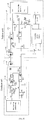
- FIG. 2 is a structural diagram of a current loop communication circuit module of an air conditioner according to an embodiment of the present disclosure. For convenience of explanation, only parts related to the embodiment of the present disclosure are shown, and details thereof are described below.
- the air conditioner current loop communication circuit includes an outdoor microcontroller unit (MCU) 10, an outdoor unit current loop communication module 20, an indoor unit current loop communication module 30, an indoor MCU 40, and a switching power supply module 50.
- MCU microcontroller unit
- the indoor unit current loop communication module 30 is connected to the outdoor unit current loop communication module 20 through a communication connection S wire (communication connection wire, communication wire, S wire, or wire S) and an AC power connection wire to form a current loop communication loop.
- the indoor MCU 40 is configured to communicate with the outdoor MCU 10 through the current loop communication loop; and the switching power supply module 50 is serially connected to the communication connection S wire or the AC power connection wire to output a DC power to the current loop communication loop.
- the air conditioner current loop communication circuit of the present disclosure includes an indoor unit part and an outdoor unit part.
- the indoor unit part of the current loop communication circuit includes the indoor unit current loop communication module 30, the indoor MCU 40, and the switching power supply module 50 at the indoor unit side.
- the outdoor unit part of the current loop communication circuit includes an outdoor unit current loop communication module 70 (outdoor unit current loop communication circuit) and the outdoor MCU 80.
- the indoor unit can communicate with the outdoor unit normally to realize the control and status information transmission and reception between the two.
- the indoor unit current loop communication module 10 mainly includes a photocoupler IC3, a photocoupler IC4, and a transistor Q2.
- the photocoupler IC3 is responsible for the communication reception of the indoor unit part of the current loop communication circuit.
- One end of the phototransistor of photocoupler IC3 is connected to the signal reception pin RXD of the indoor MCU 40.
- One end of the light emitting diode of photocoupler IC3 is an input end of the indoor unit current loop communication module 10.
- the communication of the indoor unit includes input from the input end, and then output from one end of the phototransistor to the MCU 40, so that the indoor MCU reads the received data of the communication.
- the photocoupler IC4 is responsible for the communication transmission of the indoor part of the current loop communication circuit.
- One end of the light-emitting diode of photocoupler IC4 is connected to the collector of the transistor Q2, and the base of the transistor Q2 is connected to the signal transmission pin TXD of the MCU 40.
- the communication signal sent by MCU 40 is driven by the transistor Q2 and then sent to one end of the light-emitting diode of photocoupler IC4.
- One end of the phototransistor of photocoupler IC4 is the output end of the indoor unit current loop communication module 10, so that the communication signal sent by MCU 40 is output from the output end.
- the outdoor unit current loop communication module 20 mainly includes a photocoupler IC1, a photocoupler IC2, and a transistor Q1.
- the photocoupler IC1 is responsible for the communication reception of the outdoor part of the current loop communication circuit.
- One end of the phototransistor of photocoupler IC1 is connected to the signal reception pin RXD of the outdoor MCU 10.
- One end of the light emitting diode of photocoupler IC1 is an input end of the outdoor unit current loop communication module 20.
- the communication of the outdoor unit includes input from the input end, and then output from one end of the phototransistor to the MCU 10, so that the outdoor MCU reads the received data of the communication.
- the photocoupler IC2 is responsible for the communication transmission of the outdoor part of the current loop communication circuit.
- One end of the light-emitting diode of photocoupler IC2 is connected to the collector of the transistor Q1, and the base of the transistor Q1 is connected to the signal transmission pin TXD of the MCU 10.
- the communication signal sent by MCU 10 is driven by the transistor Q1 and then sent to one end of the light-emitting diode of photocoupler IC2, to receive the communication signal sent by MCU 10.
- One end of the phototransistor of photocoupler IC2 is the output end of the outdoor unit current loop communication module 20, so that the communication signal sent by MCU 10 is output from the output end.
- the switching power supply module 50 located at the indoor unit is connected in series to the AC power N wire (AC power neutral wire), and outputs the first DC power to provide the DC power for the current loop communication loop described above. Specially, the switching power supply module 50 outputs multiple direct currents. An independent winding of the switching transformer of the switching power supply module 50, that is, the first winding, outputs the first DC power to the above-mentioned current loop communication loop to provide DC power. As shown in FIG. 2 , The switching power supply module 50 outputs an independent +24V DC power to supply DC power to the current loop communication loop.
- the positive terminal of the output end of the switching power supply module 50 is connected to the AC power N wire, and the negative terminal of the output end of the switching power supply module 50 is connected to the indoor unit current loop communication module 30. Since three wires, namely L, N, and S, are connected between the indoor unit and the outdoor unit of the air conditioner to realize current loop communication and transmission of AC power, the positive pole of the 24V DC power output from the switching power supply 50 is connected to the N wire of the AC power, that is, the positive pole of the DC power supply in the communication loop is shared with the N wire, thus the three communication connection wires of the current loop of the indoor unit and the outdoor unit are commonly used.
- the connection wire L between the indoor unit and the outdoor unit are not shown in the figure.
- the AC power transmission to the indoor unit and the outdoor unit is realized through the L and N wires.
- the 24V positive pole is input from the N wire of the indoor unit side to the current loop communication loop.
- the direct current is returned to the DC 24V negative pole via the N wire of the outdoor unit side to a photocoupler IC1 of the outdoor unit side, a photocoupler IC2 of the outdoor unit side, a photocoupler IC3 of the indoor unit side, and a photocoupler IC4 of the indoor unit side.
- the negative pole of 24V is connected to the indoor unit current loop communication module 30, for example, the output end of the communication module 30.
- the negative pole of 24V is also the common ground wire of the output of the current loop communication module 30, for example, the emitter of the transistor of the photocoupler IC4.
- other windings of switching transformer of the switching power supply module 50 also output other DC power.
- the second winding of the switching transformer outputs a second DC power of +5V, and its DC negative pole is shared with the 24V negative pole to provide the DC power needed for the indoor MCU to work.
- the switching power supply module 50 can also output other direct currents to provide DC power for other operations of the entire outdoor unit circuit, that is, the switching power supply module 50 provides direct current for the entire outdoor unit circuit.
- the switching transformer of the switching power supply module 50 Compared with the existing outdoor circuit power supply, the switching transformer of the switching power supply module 50 consistent with the present disclosure adds a winding to output a set of separate DC power to provide DC power for the current loop communication loop.
- the DC power supply of the current loop communication loop includes a voltage dividing resistor that divides the AC power source, a diode for rectification, and a voltage regulator diode for simple voltage stabilization.
- the DC power supply of the current loop communication loop of the present disclosure eliminates the voltage divider resistor which generate a large amount of heat due to excessive power consumption, and since the winding output is only extended on the existing switching power supply, the PCB layout of the current loop communication circuit is also simple, and there are no large-volume components.
- FIG. 3 is a circuit diagram showing details of the switching power supply module 50 at the indoor unit side.
- the switching power supply of the switching power supply module 50 mainly includes switching power supply control chip IC5, switching transformer T1, voltage feedback photocoupler IC14, voltage stabilization chip IC7 and IC6.
- the switching transformer T1 has two output windings, and the AC powers output by the two windings undergo rectification by diodes and regulation by the voltage regulator chips, and become two DC power outputs: 24V that provides DC power for the current loop communication loop and 5V that provides indoor MCU 40 with power required for work.
- the switching power supply module 50 in the above FIG. 2 and FIG. 3 is connected in series to the N wire of the AC power supply, or may be connected in series to the communication connection S wire. Since the indoor unit current loop communication module 10 is connected to the outdoor unit current loop communication module 70 through the communication connection S wire and the AC power connection wire L or N to form a current loop communication loop, and the switching power supply module 50 is configured to provide DC power for the current loop communication loop, whether the switching power supply module 50 is connected in series on the communication connection S wire or in series with the AC power connection wire L or N, the normal operation of the current loop communication loop can be achieved.
- the air conditioner current loop communication circuit shown in FIG. 4 differs from the air conditioner current loop communication circuit shown in FIG. 2 in that, in FIG. 4 , the switching power supply module 50 is connected in series with the L wire of the AC power supply, the positive pole (+24V) of the output end of the switching power supply module 50 is connected to the L wire of the AC power supply, and the negative pole of the output end of the switching power supply module 50 is connected to the indoor unit current loop communication module 30.
- the AC power N wire is not shown. The AC power transmission for the indoor unit and the outdoor unit is through the L and N wires.
- the air conditioner current loop communication circuit shown in FIG. 5 differs from the air conditioner current loop communication circuit shown in FIG. 2 in that, in FIG. 5 , the switching power supply module 50 is located at the outdoor unit side, the switching power supply module 50 outputs 24V DC power to the current loop communication loop via the AC N wire of the indoor unit side, and the direct current passes via the N wire of the outdoor unit side to a photocoupler IC3 of the indoor unit side, a photocoupler IC4 of the indoor unit side, a photocoupler IC1 of the outdoor unit side, and a photocoupler IC2 of the outdoor unit side and returns to the DC 24V negative pole.
- the negative pole of 24V is connected to the outdoor unit current loop communication module 20, and can be, e.g., the emitter of the transistor of the photocoupler IC2.
- the air conditioner current loop communication circuit shown in FIG. 6 differs from the air conditioner current loop communication circuit shown in FIG. 5 in that, in FIG. 6 , the switching power supply module 50 is connected in series with the L wire of the AC power supply, the positive pole (+24V) of the output end of the switching power supply module 50 is connected to the L wire of the AC power supply, and the negative pole of the output end of the switching power supply module 50 is connected to the outdoor unit current loop communication module 20.
- the AC power N wire is not shown in FIG. 6 .
- the AC power transmission for the indoor unit and the outdoor unit is through the L and N wires.
- the air conditioner current loop communication circuit includes the switching power supply module 50.
- the switching power supply module 50 is connected in series to the communication connection S wire or the AC power connection wire to output the direct current to the current loop communication loop.
- the DC power output from the switching power supply module 50 is configured to replace the existing resistance voltage divider type DC power supply circuit, and is compatible with the existing current loop communication circuit connecting wires between the indoor unit and outdoor unit of the air conditioner, which solves the problems in the existing resistance voltage divider that the large power consumption of the voltage divider resistor causes large heat generation, and that the large volume of the voltage divider resistor is not suitable to the PCB layout.
- the air conditioner current loop communication circuit further includes a unidirectional protection module 60 connected in series in the current loop communication loop to provide a unidirectional DC path for the current loop communication loop.
- the unidirectional protection module 60 includes a first diode D1.
- the first diode D1 is connected in series in a current loop communication loop, and the current in the loop is input from the positive pole of the first diode D1 and output from the negative pole of the first diode D1.
- L, N, and S such as L and S
- the first diode D1 will prevent high voltage electricity from causing damage to other components such as the photocouplers in the loop due to high voltage overcurrent.
- a unidirectional protection module can be set at each of the indoor unit side and the outdoor unit side.
- a second unidirectional protection module 70 is also connected at the indoor unit side.
- the first and second unidirectional protection modules 60 and 70 are located at the external interfaces of the communication wire S at the indoor unit and outdoor unit, respectively.
- the negative pole of the first diode D1 constituting the first unidirectional protection module 60 is connected to an output port (not shown) of the communication wire S
- the positive pole of the second diode D4 constituting the second unidirectional protection module 70 is connected to an output port (not shown) of the communication wire S.
- the first diode D1 and the second diode D4 can be configured to provide a better protection and prevent damages to other components in the indoor- and outdoor-side loops when a high voltage is introduced into the loop as a result of the indoor and outdoor unit connection wires being reversed.
- the air conditioner current loop communication circuit further includes an overcurrent protection module 80 connected in series in the current loop communication loop to provide an overcurrent protection for the current loop communication loop.
- the overcurrent protection module 80 includes a positive temperature coefficient (PTC) resistor R9, which is connected in series in the current loop communication loop.
- PTC positive temperature coefficient
- the PTC resistor R9 is connected in series at the indoor unit side.
- the PTC resistor R9 can be connected in series at the outdoor unit side.
- Sometimes a large current may occur in the current loop communication loop.
- the reverse connection of connection wires of the indoor and outdoor units may introduce a high voltage in the loop, which will cause the current in the loop to rise instantly.
- Due to the characteristics of the PTC resistor R9 when the current flowing through it increases, its temperature rises, and its resistance value rises rapidly. The increase of the resistance value enhances the current limiting function and reduces the current in the loop.
- the present disclosure further provides an air conditioner.
- the indoor unit and the outdoor unit of the air conditioner communicate with each other through the air conditioner current loop communication circuit described above.
- first embodiment means that a specific method, device, or feature described in conjunction with the embodiment or example is included in at least one embodiment or example of the present disclosure.
- the illustrative representations of the above terms need not necessarily be directed to the same embodiment or example.
- the particular features, methods, devices, or characteristics described may be combined in any suitable manner in any one or more embodiments or examples.
- those skilled in the art may combine different embodiments or examples and features of the different embodiments or examples described in this specification.
Landscapes
- Engineering & Computer Science (AREA)
- Chemical & Material Sciences (AREA)
- Combustion & Propulsion (AREA)
- Mechanical Engineering (AREA)
- General Engineering & Computer Science (AREA)
- Signal Processing (AREA)
- Computer Networks & Wireless Communication (AREA)
- Power Engineering (AREA)
- Physics & Mathematics (AREA)
- General Physics & Mathematics (AREA)
- Automation & Control Theory (AREA)
- Air Conditioning Control Device (AREA)
- Dc-Dc Converters (AREA)
Abstract
Description
- The present disclosure relates to the technical field of indoor and outdoor communication circuits of an air conditioner, and in particular, to an air conditioner current loop communication circuit and an air conditioner.
- At present, the communication between indoor and outdoor units of home air conditioner is generally implemented by a current loop communication circuit. The current loop communication is implemented by three wires, namely, the AC power live wire L, the AC power neutral wire N, and a communication wire S. As shown in
FIG. 1 , the indoor unit communicates with the outdoor unit through the current loop communication circuit composed by wire L, wire N, and wire S. The communication loop of the current loop communication circuit needs to be provided with a DC power such as 24V DC power to work normally. The DC power supply circuit includes a voltage dividing resistor that divides the AC power source, a diode for rectification, and a voltage regulator diode for simple voltage stabilization. Since the voltage shared by the voltage dividing resistor is high, there is a large power consumption during the operation of the voltage dividing resistor, which causes severe heat generation, and the volume of the voltage dividing resistor is relative large compared to other components, which is also not conducive to the PCB layout of the current loop communication circuit. - The main objective of the present disclosure is to provide an air conditioner current loop communication circuit and an air conditioner, which aim to solve the problems in the existing current communication loop circuit of the air conditioner of serious heat generation due to the large power consumption of the voltage divider resistor, and impact on PCB layout due to the large volume of the voltage divider resistor.
- In order to achieve the above objective, the present disclosure provides an air conditioner current loop communication circuit, including: an indoor unit current loop communication module, an outdoor unit current loop communication module, an indoor MCU, an outdoor MCU, and a switching power supply module.
- The indoor unit current loop communication module is connected to the outdoor unit current loop communication module through a communication connection S wire and an AC power connection wire to form a current loop communication loop; the indoor MCU is configured to communicate with the outdoor MCU through the current loop communication loop; and the switching power supply module is serially connected to the communication connection S wire or the AC power connection wire to output a DC power to the current loop communication loop.
- In an embodiment of the present disclosure, the AC power connection wire is an AC power N wire. The switching power supply module is at an air condition indoor unit side, a positive pole of an output end of the switching power supply module is connected to the AC power N wire, and a negative pole of the output end of the switching power supply module is connected to the indoor unit current loop communication module. Alternatively, the switching power supply module is at an air conditioner outdoor unit side, a positive pole of an output end of the switching power supply module is connected to the AC power N wire, and a negative pole of the output end of the switching power supply module is connected to the outdoor unit current loop communication module.
- In an embodiment of the present disclosure, the AC power connection wire is an AC power L wire. The switching power supply module is at an air conditioner indoor unit side, a positive pole of an output end of the switching power supply module is connected to the AC power L wire, and a negative pole of the output end of the switching power supply module is connected to the indoor unit current loop communication module. Alternatively, the switching power supply module is at an air conditioner outdoor unit side, a positive pole of an output end of the switching power supply module is connected to the AC power L wire, and a negative pole of the output end of the switching power supply module is connected to the outdoor unit current loop communication module.
- In an embodiment of the present disclosure, the switching power module includes a switching transformer. The switching transformer includes a first output winding.
- The first output winding is configured to output a first DC to the current loop communication loop to provide a DC power source.
- In an embodiment of the present disclosure, the air conditioner current loop communication circuit further includes a unidirectional protection module.
- The unidirectional protection module is connected in series in the current loop communication loop to provide a unidirectional DC path for the current loop communication loop.
- In an embodiment of the present disclosure, the unidirectional protection module comprises: a first unidirectional protection module connected in series in an indoor unit part of the current loop communication loop; and a second unidirectional protection module connected in series in an outdoor unit part of the current loop communication loop.
- In an embodiment of the present disclosure, the first unidirectional protection module comprises a first diode, and the second unidirectional protection module comprises a second diode.
- In an embodiment of the present disclosure, the air conditioner current loop communication circuit further includes an overcurrent protection module.
- The overcurrent protection module is connected in series in the current loop communication loop to provide an overcurrent protection for the current loop communication loop.
- In an embodiment of the present disclosure, the overcurrent protection module is a PTC resistor.
- The PTC resistor is connected in series in the current loop communication loop.
- In order to achieve the above objective, the present disclosure further provides an air conditioner, including the air conditioner current loop communication circuit described above.
- The present disclosure provides an air conditioner current loop communication circuit. The air conditioner current loop communication circuit includes the switching power supply module connected in series to the communication connection S wire or the AC power connection wire to output the direct current to the current loop communication loop. In the present disclosure, the DC power output from the switching power supply module is configured to replace the existing resistance voltage divider type DC power supply circuit, and is compatible with the existing current loop communication circuit connecting wires between the indoor unit and outdoor unit of the air conditioner, which solves the problems in the existing resistance voltage divider that the large power consumption of the voltage divider resistor causes large heat generation, and that the large volume of the voltage divider resistor is not suitable to the PCB layout.
-
-
FIG. 1 is a schematic diagram of a current loop communication connection wire of an indoor unit and an outdoor unit of an air conditioner according to the related art; -
FIG. 2 is a circuit structural diagram of the air conditioner current loop communication circuit according to an embodiment of the present disclosure; -
FIG. 3 is a specific circuit structure diagram of the switching power supply module inFIG. 2 ; -
FIG. 4 is another circuit structural diagram of the air conditioner current loop communication circuit according to an embodiment of the present disclosure; -
FIG. 5 is another circuit structural diagram of the air conditioner current loop communication circuit according to an embodiment of the present disclosure; and -
FIG. 6 is another circuit structural diagram of the air conditioner current loop communication circuit according to an embodiment of the present disclosure. - The embodiments of the present disclosure are described in detail below. Examples of the embodiments are shown in the drawings. The same or similar reference numerals represent the same or similar elements or elements having the same or similar functions. The embodiments described below with reference to the drawings are exemplary and are intended to explain the present disclosure, but should not be construed as limiting the present disclosure.
- Referring to
FIG. 2, FIG. 2 is a structural diagram of a current loop communication circuit module of an air conditioner according to an embodiment of the present disclosure. For convenience of explanation, only parts related to the embodiment of the present disclosure are shown, and details thereof are described below. - The air conditioner current loop communication circuit provided by the embodiment of the present disclosure includes an outdoor microcontroller unit (MCU) 10, an outdoor unit current
loop communication module 20, an indoor unit currentloop communication module 30, anindoor MCU 40, and a switchingpower supply module 50. - The indoor unit current
loop communication module 30 is connected to the outdoor unit currentloop communication module 20 through a communication connection S wire (communication connection wire, communication wire, S wire, or wire S) and an AC power connection wire to form a current loop communication loop. Theindoor MCU 40 is configured to communicate with theoutdoor MCU 10 through the current loop communication loop; and the switchingpower supply module 50 is serially connected to the communication connection S wire or the AC power connection wire to output a DC power to the current loop communication loop. - Specially, as shown in
FIG. 2 , the air conditioner current loop communication circuit of the present disclosure includes an indoor unit part and an outdoor unit part. - The indoor unit part of the current loop communication circuit includes the indoor unit current
loop communication module 30, theindoor MCU 40, and the switchingpower supply module 50 at the indoor unit side. - The outdoor unit part of the current loop communication circuit includes an outdoor unit current loop communication module 70 (outdoor unit current loop communication circuit) and the
outdoor MCU 80. - Based on the communication between the
indoor MCU 40 and theoutdoor MCU 10, the indoor unit can communicate with the outdoor unit normally to realize the control and status information transmission and reception between the two. - The indoor unit current
loop communication module 10 mainly includes a photocoupler IC3, a photocoupler IC4, and a transistor Q2. The photocoupler IC3 is responsible for the communication reception of the indoor unit part of the current loop communication circuit. One end of the phototransistor of photocoupler IC3 is connected to the signal reception pin RXD of theindoor MCU 40. One end of the light emitting diode of photocoupler IC3 is an input end of the indoor unit currentloop communication module 10. The communication of the indoor unit includes input from the input end, and then output from one end of the phototransistor to theMCU 40, so that the indoor MCU reads the received data of the communication. The photocoupler IC4 is responsible for the communication transmission of the indoor part of the current loop communication circuit. One end of the light-emitting diode of photocoupler IC4 is connected to the collector of the transistor Q2, and the base of the transistor Q2 is connected to the signal transmission pin TXD of theMCU 40. The communication signal sent byMCU 40 is driven by the transistor Q2 and then sent to one end of the light-emitting diode of photocoupler IC4. One end of the phototransistor of photocoupler IC4 is the output end of the indoor unit currentloop communication module 10, so that the communication signal sent byMCU 40 is output from the output end. - The outdoor unit current
loop communication module 20 mainly includes a photocoupler IC1, a photocoupler IC2, and a transistor Q1. The photocoupler IC1 is responsible for the communication reception of the outdoor part of the current loop communication circuit. One end of the phototransistor of photocoupler IC1 is connected to the signal reception pin RXD of theoutdoor MCU 10. One end of the light emitting diode of photocoupler IC1 is an input end of the outdoor unit currentloop communication module 20. The communication of the outdoor unit includes input from the input end, and then output from one end of the phototransistor to theMCU 10, so that the outdoor MCU reads the received data of the communication. The photocoupler IC2 is responsible for the communication transmission of the outdoor part of the current loop communication circuit. One end of the light-emitting diode of photocoupler IC2 is connected to the collector of the transistor Q1, and the base of the transistor Q1 is connected to the signal transmission pin TXD of theMCU 10. The communication signal sent byMCU 10 is driven by the transistor Q1 and then sent to one end of the light-emitting diode of photocoupler IC2, to receive the communication signal sent byMCU 10. One end of the phototransistor of photocoupler IC2 is the output end of the outdoor unit currentloop communication module 20, so that the communication signal sent byMCU 10 is output from the output end. - The switching
power supply module 50 located at the indoor unit is connected in series to the AC power N wire (AC power neutral wire), and outputs the first DC power to provide the DC power for the current loop communication loop described above. Specially, the switchingpower supply module 50 outputs multiple direct currents. An independent winding of the switching transformer of the switchingpower supply module 50, that is, the first winding, outputs the first DC power to the above-mentioned current loop communication loop to provide DC power. As shown inFIG. 2 , The switchingpower supply module 50 outputs an independent +24V DC power to supply DC power to the current loop communication loop. The positive terminal of the output end of the switchingpower supply module 50 is connected to the AC power N wire, and the negative terminal of the output end of the switchingpower supply module 50 is connected to the indoor unit currentloop communication module 30. Since three wires, namely L, N, and S, are connected between the indoor unit and the outdoor unit of the air conditioner to realize current loop communication and transmission of AC power, the positive pole of the 24V DC power output from the switchingpower supply 50 is connected to the N wire of the AC power, that is, the positive pole of the DC power supply in the communication loop is shared with the N wire, thus the three communication connection wires of the current loop of the indoor unit and the outdoor unit are commonly used. The connection wire L between the indoor unit and the outdoor unit are not shown in the figure. In fact, the AC power transmission to the indoor unit and the outdoor unit is realized through the L and N wires. InFIG. 2 , the 24V positive pole is input from the N wire of the indoor unit side to the current loop communication loop. The direct current is returned to theDC 24V negative pole via the N wire of the outdoor unit side to a photocoupler IC1 of the outdoor unit side, a photocoupler IC2 of the outdoor unit side, a photocoupler IC3 of the indoor unit side, and a photocoupler IC4 of the indoor unit side. The negative pole of 24V is connected to the indoor unit currentloop communication module 30, for example, the output end of thecommunication module 30. The negative pole of 24V is also the common ground wire of the output of the currentloop communication module 30, for example, the emitter of the transistor of the photocoupler IC4. In addition to the +24V provided by the switchingpower supply module 50, other windings of switching transformer of the switchingpower supply module 50 also output other DC power. For example, the second winding of the switching transformer outputs a second DC power of +5V, and its DC negative pole is shared with the 24V negative pole to provide the DC power needed for the indoor MCU to work. The switchingpower supply module 50 can also output other direct currents to provide DC power for other operations of the entire outdoor unit circuit, that is, the switchingpower supply module 50 provides direct current for the entire outdoor unit circuit. Compared with the existing outdoor circuit power supply, the switching transformer of the switchingpower supply module 50 consistent with the present disclosure adds a winding to output a set of separate DC power to provide DC power for the current loop communication loop. In the existing art, the DC power supply of the current loop communication loop includes a voltage dividing resistor that divides the AC power source, a diode for rectification, and a voltage regulator diode for simple voltage stabilization. Thus, compared with the existing DC power supply of the current loop communication loop, the DC power supply of the current loop communication loop of the present disclosure eliminates the voltage divider resistor which generate a large amount of heat due to excessive power consumption, and since the winding output is only extended on the existing switching power supply, the PCB layout of the current loop communication circuit is also simple, and there are no large-volume components. -
FIG. 3 is a circuit diagram showing details of the switchingpower supply module 50 at the indoor unit side. The switching power supply of the switchingpower supply module 50 mainly includes switching power supply control chip IC5, switching transformer T1, voltage feedback photocoupler IC14, voltage stabilization chip IC7 and IC6. The switching transformer T1 has two output windings, and the AC powers output by the two windings undergo rectification by diodes and regulation by the voltage regulator chips, and become two DC power outputs: 24V that provides DC power for the current loop communication loop and 5V that providesindoor MCU 40 with power required for work. - The switching
power supply module 50 in the aboveFIG. 2 andFIG. 3 is connected in series to the N wire of the AC power supply, or may be connected in series to the communication connection S wire. Since the indoor unit currentloop communication module 10 is connected to the outdoor unit currentloop communication module 70 through the communication connection S wire and the AC power connection wire L or N to form a current loop communication loop, and the switchingpower supply module 50 is configured to provide DC power for the current loop communication loop, whether the switchingpower supply module 50 is connected in series on the communication connection S wire or in series with the AC power connection wire L or N, the normal operation of the current loop communication loop can be achieved. - Further, the air conditioner current loop communication circuit shown in
FIG. 4 differs from the air conditioner current loop communication circuit shown inFIG. 2 in that, inFIG. 4 , the switchingpower supply module 50 is connected in series with the L wire of the AC power supply, the positive pole (+24V) of the output end of the switchingpower supply module 50 is connected to the L wire of the AC power supply, and the negative pole of the output end of the switchingpower supply module 50 is connected to the indoor unit currentloop communication module 30. InFIG. 4 , the AC power N wire is not shown. The AC power transmission for the indoor unit and the outdoor unit is through the L and N wires. - Further, the air conditioner current loop communication circuit shown in
FIG. 5 differs from the air conditioner current loop communication circuit shown inFIG. 2 in that, inFIG. 5 , the switchingpower supply module 50 is located at the outdoor unit side, the switchingpower supply module 50outputs 24V DC power to the current loop communication loop via the AC N wire of the indoor unit side, and the direct current passes via the N wire of the outdoor unit side to a photocoupler IC3 of the indoor unit side, a photocoupler IC4 of the indoor unit side, a photocoupler IC1 of the outdoor unit side, and a photocoupler IC2 of the outdoor unit side and returns to theDC 24V negative pole. The negative pole of 24V is connected to the outdoor unit currentloop communication module 20, and can be, e.g., the emitter of the transistor of the photocoupler IC2. - Further, the air conditioner current loop communication circuit shown in
FIG. 6 differs from the air conditioner current loop communication circuit shown inFIG. 5 in that, inFIG. 6 , the switchingpower supply module 50 is connected in series with the L wire of the AC power supply, the positive pole (+24V) of the output end of the switchingpower supply module 50 is connected to the L wire of the AC power supply, and the negative pole of the output end of the switchingpower supply module 50 is connected to the outdoor unit currentloop communication module 20. The AC power N wire is not shown inFIG. 6 . The AC power transmission for the indoor unit and the outdoor unit is through the L and N wires. - In the embodiments of the present disclosure, the air conditioner current loop communication circuit includes the switching
power supply module 50. The switchingpower supply module 50 is connected in series to the communication connection S wire or the AC power connection wire to output the direct current to the current loop communication loop. In the present disclosure, the DC power output from the switchingpower supply module 50 is configured to replace the existing resistance voltage divider type DC power supply circuit, and is compatible with the existing current loop communication circuit connecting wires between the indoor unit and outdoor unit of the air conditioner, which solves the problems in the existing resistance voltage divider that the large power consumption of the voltage divider resistor causes large heat generation, and that the large volume of the voltage divider resistor is not suitable to the PCB layout. - Further, as shown in
FIG. 2 , the air conditioner current loop communication circuit further includes aunidirectional protection module 60 connected in series in the current loop communication loop to provide a unidirectional DC path for the current loop communication loop. In some embodiments, theunidirectional protection module 60 includes a first diode D1. The first diode D1 is connected in series in a current loop communication loop, and the current in the loop is input from the positive pole of the first diode D1 and output from the negative pole of the first diode D1. When two of the three connection wires L, N, and S (such as L and S) of the indoor unit and the outdoor unit are reversely connected, high-voltage electricity is introduced into the current loop communication loop. At this time, the first diode D1 will prevent high voltage electricity from causing damage to other components such as the photocouplers in the loop due to high voltage overcurrent. - Further, in order to achieve better high-voltage protection, a unidirectional protection module can be set at each of the indoor unit side and the outdoor unit side. As shown in
FIG. 2 , in addition to the firstunidirectional protection module 60 at the outdoor unit side, a secondunidirectional protection module 70 is also connected at the indoor unit side. The first and secondunidirectional protection modules unidirectional protection module 60 is connected to an output port (not shown) of the communication wire S, and the positive pole of the second diode D4 constituting the secondunidirectional protection module 70 is connected to an output port (not shown) of the communication wire S. The first diode D1 and the second diode D4 can be configured to provide a better protection and prevent damages to other components in the indoor- and outdoor-side loops when a high voltage is introduced into the loop as a result of the indoor and outdoor unit connection wires being reversed. - Further, as shown in
FIG. 2 , the air conditioner current loop communication circuit further includes anovercurrent protection module 80 connected in series in the current loop communication loop to provide an overcurrent protection for the current loop communication loop. In some embodiments, theovercurrent protection module 80 includes a positive temperature coefficient (PTC) resistor R9, which is connected in series in the current loop communication loop. InFIG. 2 , the PTC resistor R9 is connected in series at the indoor unit side. Specially, the PTC resistor R9 can be connected in series at the outdoor unit side. Sometimes a large current may occur in the current loop communication loop. For example, as described above, the reverse connection of connection wires of the indoor and outdoor units may introduce a high voltage in the loop, which will cause the current in the loop to rise instantly. Due to the characteristics of the PTC resistor R9, when the current flowing through it increases, its temperature rises, and its resistance value rises rapidly. The increase of the resistance value enhances the current limiting function and reduces the current in the loop. - The present disclosure further provides an air conditioner. The indoor unit and the outdoor unit of the air conditioner communicate with each other through the air conditioner current loop communication circuit described above. For the specific implementation and effects, reference may be made to the foregoing embodiments, and details are not described herein again.
- In the specification, the description of the terms "first embodiment," "second embodiment," "example" and the like means that a specific method, device, or feature described in conjunction with the embodiment or example is included in at least one embodiment or example of the present disclosure. In the specification, the illustrative representations of the above terms need not necessarily be directed to the same embodiment or example. Moreover, the particular features, methods, devices, or characteristics described may be combined in any suitable manner in any one or more embodiments or examples. In addition, without any contradiction, those skilled in the art may combine different embodiments or examples and features of the different embodiments or examples described in this specification.
- The above are only some embodiments of the present disclosure, and thus do not limit the scope of the present disclosure. Under the concept of the present disclosure, the equivalent structural transformations made according to the present specification and the drawings, or direct or indirect applications to other related technical fields, and are included in the scope of the present disclosure.
Claims (10)
- An air conditioner current loop communication circuit, comprising an indoor unit current loop communication module, an outdoor unit current loop communication module, an indoor microcontroller unit (MCU), an outdoor MCU, and a switching power supply module, wherein:the indoor unit current loop communication module is connected to the outdoor unit current loop communication module through a communication connection wire (S) and an AC power connection wire to form a current loop communication loop;the indoor MCU is configured to communicate with the outdoor MCU through the current loop communication loop; andthe switching power supply module is connected in series to the communication connection wire (S) or the AC power connection wire to output a DC power to the current loop communication loop.
- The air conditioner current loop communication circuit of claim 1, wherein:the AC power connection wire includes an AC power neutral wire;the switching power supply module is located in an indoor unit of an air conditioner, a positive pole of an output end of the switching power supply module is connected to the AC power neutral wire, and a negative pole of the output end of the switching power supply module is connected to the indoor unit current loop communication module; orthe switching power supply module is located in an outdoor unit of an air conditioner, a positive pole of an output end of the switching power supply module is connected to the AC power neutral wire, and a negative pole of the output end of the switching power supply module is connected to the outdoor unit current loop communication module.
- The air conditioner current loop communication circuit of claim 1, wherein:the AC power connection wire includes an AC power live wire;the switching power supply module is located in an indoor unit of an air conditioner, a positive pole of an output end of the switching power supply module is connected to the AC power live wire, and a negative pole of the output end of the switching power supply module is connected to the indoor unit current loop communication module; orthe switching power supply module is located in an outdoor unit of an air conditioner, a positive pole of an output end of the switching power supply module is connected to the AC power live wire, and a negative pole of the output end of the switching power supply module is connected to the outdoor unit current loop communication module.
- The air conditioner current loop communication circuit of any one of claims 1 to 3, wherein the switching power module comprises a switching transformer comprising:
a first output winding configured to output a first DC power to the current loop communication loop. - The air conditioner current loop communication circuit of any one of claims 1 to 3, further comprising:
a unidirectional protection module connected in series in the current loop communication loop to provide a unidirectional DC path for the current loop communication loop. - The air conditioner current loop communication circuit of claim 5, wherein:
the unidirectional protection module comprises:a first unidirectional protection module connected in series in an indoor unit part of the current loop communication loop; anda second unidirectional protection module connected in series in an outdoor unit part of the current loop communication loop . - The air conditioner current loop communication circuit of claim 6, wherein:the first unidirectional protection module comprises a first diode connected in series in the indoor unit part of the current loop communication loop; andthe second unidirectional protection module comprises a second diode connected in series in the outdoor unit part of the current loop communication loop located inside.
- The air conditioner current loop communication circuit of any one of claims 1 to 3, further comprising:
an overcurrent protection module connected in series in the current loop communication loop to provide an overcurrent protection for the current loop communication loop. - The air conditioner current loop communication circuit of claim 8, wherein the overcurrent protection module is a positive temperature coefficient resistor connected in series in the current loop communication loop.
- An air conditioner, comprising the air conditioner current loop communication circuit of any one of claims 1 to 3.
Priority Applications (2)
| Application Number | Priority Date | Filing Date | Title |
|---|---|---|---|
| HRP20210629TT HRP20210629T1 (en) | 2017-08-04 | 2017-11-29 | Air conditioner current loop communication circuit and air conditioner |
| PL17920529T PL3644519T3 (en) | 2017-08-04 | 2017-11-29 | Air conditioner current loop communication circuit and air conditioner |
Applications Claiming Priority (2)
| Application Number | Priority Date | Filing Date | Title |
|---|---|---|---|
| CN201710665388.0A CN107547109B (en) | 2017-08-04 | 2017-08-04 | Air conditioner current loop communication circuit and air conditioner |
| PCT/CN2017/113502 WO2019024349A1 (en) | 2017-08-04 | 2017-11-29 | Air conditioner current loop communication circuit and air conditioner |
Publications (3)
| Publication Number | Publication Date |
|---|---|
| EP3644519A1 true EP3644519A1 (en) | 2020-04-29 |
| EP3644519A4 EP3644519A4 (en) | 2020-04-29 |
| EP3644519B1 EP3644519B1 (en) | 2021-03-17 |
Family
ID=60970463
Family Applications (1)
| Application Number | Title | Priority Date | Filing Date |
|---|---|---|---|
| EP17920529.9A Active EP3644519B1 (en) | 2017-08-04 | 2017-11-29 | Air conditioner current loop communication circuit and air conditioner |
Country Status (8)
| Country | Link |
|---|---|
| US (1) | US11378294B2 (en) |
| EP (1) | EP3644519B1 (en) |
| JP (1) | JP2020527327A (en) |
| CN (1) | CN107547109B (en) |
| ES (1) | ES2871979T3 (en) |
| HR (1) | HRP20210629T1 (en) |
| PL (1) | PL3644519T3 (en) |
| WO (1) | WO2019024349A1 (en) |
Cited By (1)
| Publication number | Priority date | Publication date | Assignee | Title |
|---|---|---|---|---|
| EP3944484A1 (en) * | 2020-07-24 | 2022-01-26 | Guangdong Giwee Technology Co., Ltd. | Communication circuit for indoor and outdoor units of air conditioner and air conditioner |
Families Citing this family (8)
| Publication number | Priority date | Publication date | Assignee | Title |
|---|---|---|---|---|
| CN109140700B (en) * | 2018-08-03 | 2019-12-03 | 珠海格力电器股份有限公司 | Communication device for air conditioner internal and external units, air conditioner and communication method for internal and external units |
| CN109442595A (en) * | 2018-11-05 | 2019-03-08 | 广东美的制冷设备有限公司 | Air conditioner and its outdoor unit control circuit |
| CN109345810A (en) * | 2018-11-20 | 2019-02-15 | 安徽奕甲文化传媒有限责任公司 | Show piece safety monitoring system |
| CN111976415B (en) * | 2019-05-23 | 2022-02-11 | 广东美的制冷设备有限公司 | Outdoor unit electric control device and vehicle-mounted air conditioner |
| CN111697996A (en) * | 2020-07-03 | 2020-09-22 | 安徽中家智康科技有限公司 | Simulation and communication monitoring device and method for indoor and outdoor units of air conditioner |
| CN112524686B (en) * | 2020-11-30 | 2023-01-13 | 青岛海尔空调器有限总公司 | Air conditioner |
| CN114400659A (en) * | 2022-01-13 | 2022-04-26 | 珠海格力电器股份有限公司 | Zero-live wire self-adjusting circuit and method and air conditioner |
| JP7385149B2 (en) * | 2022-03-31 | 2023-11-22 | ダイキン工業株式会社 | Air conditioning related equipment and air conditioning systems |
Family Cites Families (30)
| Publication number | Priority date | Publication date | Assignee | Title |
|---|---|---|---|---|
| US5225765A (en) * | 1984-08-15 | 1993-07-06 | Michael Callahan | Inductorless controlled transition and other light dimmers |
| JPH05316727A (en) * | 1992-05-11 | 1993-11-26 | Tokyo Electric Co Ltd | Switching power source |
| CN1080697A (en) | 1992-06-30 | 1994-01-12 | 吴汰鸿 | Inclined plane ceiling fan |
| JP3124118B2 (en) * | 1992-09-11 | 2001-01-15 | 三菱重工業株式会社 | Air conditioner signal transfer circuit device |
| JP2001045752A (en) * | 1999-07-27 | 2001-02-16 | Canon Inc | Power supply |
| JP3835174B2 (en) * | 2001-01-22 | 2006-10-18 | 松下電器産業株式会社 | Indoor / outdoor communication control device for air conditioner |
| JP2003287264A (en) * | 2002-03-27 | 2003-10-10 | Mitsubishi Electric Corp | Indoor / outdoor communication control device for air conditioner and communication control device for air conditioner and equipment |
| US20080054084A1 (en) | 2006-08-29 | 2008-03-06 | American Standard International Inc. | Two-wire power and communication link for a thermostat |
| US7997869B2 (en) | 2007-05-30 | 2011-08-16 | Fanimation, Inc. | Fan assembly having protective motor housing that accommodates cyclic movement |
| US8152453B2 (en) | 2007-09-17 | 2012-04-10 | Delta T Corporation | Ceiling fan with angled mounting |
| JP2009097760A (en) * | 2007-10-15 | 2009-05-07 | Toshiba Carrier Corp | Air conditioner communication control device |
| JP2012060855A (en) * | 2010-09-13 | 2012-03-22 | Yokogawa Electric Corp | Primary-side circuit for switching power supply device |
| US9268344B2 (en) * | 2010-11-19 | 2016-02-23 | Google Inc. | Installation of thermostat powered by rechargeable battery |
| CN202178711U (en) * | 2011-04-02 | 2012-03-28 | 广东美的电器股份有限公司 | Dual supply output circuit possessing ultralow no-load power consumption and high efficiency under low load |
| CN202109612U (en) * | 2011-06-13 | 2012-01-11 | 珠海格力电器股份有限公司 | Standby power consumption control system of outdoor unit of air conditioner |
| KR101858938B1 (en) * | 2011-09-19 | 2018-06-29 | 삼성전자주식회사 | Air conditioner |
| CN202334333U (en) * | 2011-12-15 | 2012-07-11 | Tcl空调器(中山)有限公司 | A full DC inverter air conditioner power supply control system |
| US9325180B2 (en) * | 2012-09-14 | 2016-04-26 | Astronics Advanced Electronic Systems Corp. | USB power supply |
| CN103837820B (en) * | 2012-11-27 | 2016-07-06 | 广东美的制冷设备有限公司 | The communication detecting method of a kind of current-loop communication circuit and system |
| CN203272206U (en) | 2013-05-16 | 2013-11-06 | 广东美的环境电器制造有限公司 | Connection device used for fan and fan with same |
| CN104345729B (en) * | 2013-08-07 | 2017-03-29 | 海尔集团公司 | A kind of power control circuit based on electric current loop order circuit |
| CN104154604B (en) * | 2014-08-20 | 2017-01-18 | 中国扬子集团滁州扬子空调器有限公司 | Outdoor unit control circuit of variable frequency air conditioner |
| CN106664026B (en) * | 2014-09-25 | 2019-11-15 | 英特尔公司 | Power supply units for different power modes |
| CN104596049B (en) * | 2014-12-26 | 2017-05-31 | 广东美的制冷设备有限公司 | Current loop communication circuit and air-conditioner |
| CN204478392U (en) * | 2014-12-26 | 2015-07-15 | 广东美的制冷设备有限公司 | Current loop communication circuit and air-conditioner |
| CN104776559B (en) | 2015-03-30 | 2017-11-10 | 广东美的制冷设备有限公司 | A kind of convertible frequency air-conditioner and its bus-type electric current loop communication system |
| CN204787051U (en) * | 2015-06-30 | 2015-11-18 | 广东美的制冷设备有限公司 | Air conditioner and off -premises station supply control circuit thereof |
| JP6620559B2 (en) * | 2016-01-07 | 2019-12-18 | コニカミノルタ株式会社 | Power supply device and image forming apparatus |
| CN106225105B (en) * | 2016-09-20 | 2022-03-01 | 广东美的制冷设备有限公司 | Current loop communication device and air conditioner |
| CN106545955B (en) * | 2016-10-08 | 2021-05-04 | 珠海格力电器股份有限公司 | Communication relay device and method and air conditioner |
-
2017
- 2017-08-04 CN CN201710665388.0A patent/CN107547109B/en active Active
- 2017-11-29 HR HRP20210629TT patent/HRP20210629T1/en unknown
- 2017-11-29 WO PCT/CN2017/113502 patent/WO2019024349A1/en not_active Ceased
- 2017-11-29 ES ES17920529T patent/ES2871979T3/en active Active
- 2017-11-29 EP EP17920529.9A patent/EP3644519B1/en active Active
- 2017-11-29 PL PL17920529T patent/PL3644519T3/en unknown
- 2017-11-29 JP JP2020503021A patent/JP2020527327A/en active Pending
-
2020
- 2020-01-23 US US16/750,445 patent/US11378294B2/en active Active
Cited By (1)
| Publication number | Priority date | Publication date | Assignee | Title |
|---|---|---|---|---|
| EP3944484A1 (en) * | 2020-07-24 | 2022-01-26 | Guangdong Giwee Technology Co., Ltd. | Communication circuit for indoor and outdoor units of air conditioner and air conditioner |
Also Published As
| Publication number | Publication date |
|---|---|
| CN107547109B (en) | 2021-05-25 |
| WO2019024349A1 (en) | 2019-02-07 |
| JP2020527327A (en) | 2020-09-03 |
| EP3644519B1 (en) | 2021-03-17 |
| US20200158364A1 (en) | 2020-05-21 |
| PL3644519T3 (en) | 2021-10-11 |
| CN107547109A (en) | 2018-01-05 |
| HRP20210629T1 (en) | 2021-06-25 |
| EP3644519A4 (en) | 2020-04-29 |
| US11378294B2 (en) | 2022-07-05 |
| ES2871979T3 (en) | 2021-11-02 |
Similar Documents
| Publication | Publication Date | Title |
|---|---|---|
| US11378294B2 (en) | Air conditioner current loop communication circuit and air conditioner | |
| AU2020209621B2 (en) | Outdoor unit of air conditioner, and air conditioner | |
| AU2016310328B2 (en) | High-power power supply for use with display devices and associated display device | |
| US11668489B2 (en) | Communication circuit for indoor and outdoor units of air conditioner and air conditioner | |
| CN115065051A (en) | Signal injection circuit and injection method | |
| CN106225105A (en) | Current ring communication device and air-conditioner | |
| CN216564925U (en) | Multi-output power supply | |
| CN205622530U (en) | Electrical power generating system with short -circuit protection | |
| CN207265865U (en) | A kind of inverse-excitation type switch power-supply circuit | |
| CN215072152U (en) | A power circuit and electrical equipment | |
| CN216699835U (en) | Flyback converter with low cross regulation rate | |
| CN213879677U (en) | Direct current motor control circuit | |
| CN211908763U (en) | Logic power supply switch control circuit | |
| CN106604472B (en) | LED driver circuit | |
| CN209805697U (en) | Single live wire power supply circuit | |
| CN104684175B (en) | A kind of opto-coupled feedback constant current driver circuit for LED and LED illumination device | |
| CN213243518U (en) | Power-down protection circuit, LED driving power supply, driving board card and display device | |
| CN218976567U (en) | Regulatory feedback circuit, switching power supply circuit and charging equipment | |
| CN104684176B (en) | A kind of opto-coupled feedback LED drive circuit and LED illumination device | |
| CN211830192U (en) | Power supply control circuit and air conditioner | |
| CN217785435U (en) | Indoor and outdoor communication circuit of air conditioner and air conditioner | |
| CN205883633U (en) | Point screen ware | |
| CN106535420B (en) | LED driver circuit | |
| CN222072803U (en) | A new type of charging and discharging control system and battery protection board | |
| CN217428024U (en) | Controller adopting silicon controlled rectifier |
Legal Events
| Date | Code | Title | Description |
|---|---|---|---|
| STAA | Information on the status of an ep patent application or granted ep patent |
Free format text: STATUS: THE INTERNATIONAL PUBLICATION HAS BEEN MADE |
|
| PUAI | Public reference made under article 153(3) epc to a published international application that has entered the european phase |
Free format text: ORIGINAL CODE: 0009012 |
|
| STAA | Information on the status of an ep patent application or granted ep patent |
Free format text: STATUS: REQUEST FOR EXAMINATION WAS MADE |
|
| 17P | Request for examination filed |
Effective date: 20200124 |
|
| A4 | Supplementary search report drawn up and despatched |
Effective date: 20200304 |
|
| AK | Designated contracting states |
Kind code of ref document: A1 Designated state(s): AL AT BE BG CH CY CZ DE DK EE ES FI FR GB GR HR HU IE IS IT LI LT LU LV MC MK MT NL NO PL PT RO RS SE SI SK SM TR |
|
| AX | Request for extension of the european patent |
Extension state: BA ME |
|
| DAV | Request for validation of the european patent (deleted) | ||
| DAX | Request for extension of the european patent (deleted) | ||
| GRAP | Despatch of communication of intention to grant a patent |
Free format text: ORIGINAL CODE: EPIDOSNIGR1 |
|
| STAA | Information on the status of an ep patent application or granted ep patent |
Free format text: STATUS: GRANT OF PATENT IS INTENDED |
|
| INTG | Intention to grant announced |
Effective date: 20201223 |
|
| GRAS | Grant fee paid |
Free format text: ORIGINAL CODE: EPIDOSNIGR3 |
|
| GRAA | (expected) grant |
Free format text: ORIGINAL CODE: 0009210 |
|
| STAA | Information on the status of an ep patent application or granted ep patent |
Free format text: STATUS: THE PATENT HAS BEEN GRANTED |
|
| AK | Designated contracting states |
Kind code of ref document: B1 Designated state(s): AL AT BE BG CH CY CZ DE DK EE ES FI FR GB GR HR HU IE IS IT LI LT LU LV MC MK MT NL NO PL PT RO RS SE SI SK SM TR |
|
| REG | Reference to a national code |
Ref country code: GB Ref legal event code: FG4D |
|
| REG | Reference to a national code |
Ref country code: CH Ref legal event code: EP |
|
| REG | Reference to a national code |
Ref country code: DE Ref legal event code: R096 Ref document number: 602017035033 Country of ref document: DE |
|
| REG | Reference to a national code |
Ref country code: IE Ref legal event code: FG4D |
|
| REG | Reference to a national code |
Ref country code: AT Ref legal event code: REF Ref document number: 1373216 Country of ref document: AT Kind code of ref document: T Effective date: 20210415 |
|
| REG | Reference to a national code |
Ref country code: HR Ref legal event code: TUEP Ref document number: P20210629T Country of ref document: HR |
|
| REG | Reference to a national code |
Ref country code: GR Ref legal event code: EP Ref document number: 20210401087 Country of ref document: GR Effective date: 20210519 |
|
| REG | Reference to a national code |
Ref country code: HR Ref legal event code: T1PR Ref document number: P20210629 Country of ref document: HR |
|
| REG | Reference to a national code |
Ref country code: LT Ref legal event code: MG9D |
|
| PG25 | Lapsed in a contracting state [announced via postgrant information from national office to epo] |
Ref country code: BG Free format text: LAPSE BECAUSE OF FAILURE TO SUBMIT A TRANSLATION OF THE DESCRIPTION OR TO PAY THE FEE WITHIN THE PRESCRIBED TIME-LIMIT Effective date: 20210617 Ref country code: FI Free format text: LAPSE BECAUSE OF FAILURE TO SUBMIT A TRANSLATION OF THE DESCRIPTION OR TO PAY THE FEE WITHIN THE PRESCRIBED TIME-LIMIT Effective date: 20210317 Ref country code: NO Free format text: LAPSE BECAUSE OF FAILURE TO SUBMIT A TRANSLATION OF THE DESCRIPTION OR TO PAY THE FEE WITHIN THE PRESCRIBED TIME-LIMIT Effective date: 20210617 |
|
| REG | Reference to a national code |
Ref country code: AT Ref legal event code: MK05 Ref document number: 1373216 Country of ref document: AT Kind code of ref document: T Effective date: 20210317 |
|
| REG | Reference to a national code |
Ref country code: NL Ref legal event code: MP Effective date: 20210317 |
|
| PG25 | Lapsed in a contracting state [announced via postgrant information from national office to epo] |
Ref country code: SE Free format text: LAPSE BECAUSE OF FAILURE TO SUBMIT A TRANSLATION OF THE DESCRIPTION OR TO PAY THE FEE WITHIN THE PRESCRIBED TIME-LIMIT Effective date: 20210317 Ref country code: RS Free format text: LAPSE BECAUSE OF FAILURE TO SUBMIT A TRANSLATION OF THE DESCRIPTION OR TO PAY THE FEE WITHIN THE PRESCRIBED TIME-LIMIT Effective date: 20210317 Ref country code: LV Free format text: LAPSE BECAUSE OF FAILURE TO SUBMIT A TRANSLATION OF THE DESCRIPTION OR TO PAY THE FEE WITHIN THE PRESCRIBED TIME-LIMIT Effective date: 20210317 |
|
| PG25 | Lapsed in a contracting state [announced via postgrant information from national office to epo] |
Ref country code: NL Free format text: LAPSE BECAUSE OF FAILURE TO SUBMIT A TRANSLATION OF THE DESCRIPTION OR TO PAY THE FEE WITHIN THE PRESCRIBED TIME-LIMIT Effective date: 20210317 |
|
| PG25 | Lapsed in a contracting state [announced via postgrant information from national office to epo] |
Ref country code: AT Free format text: LAPSE BECAUSE OF FAILURE TO SUBMIT A TRANSLATION OF THE DESCRIPTION OR TO PAY THE FEE WITHIN THE PRESCRIBED TIME-LIMIT Effective date: 20210317 Ref country code: SM Free format text: LAPSE BECAUSE OF FAILURE TO SUBMIT A TRANSLATION OF THE DESCRIPTION OR TO PAY THE FEE WITHIN THE PRESCRIBED TIME-LIMIT Effective date: 20210317 Ref country code: EE Free format text: LAPSE BECAUSE OF FAILURE TO SUBMIT A TRANSLATION OF THE DESCRIPTION OR TO PAY THE FEE WITHIN THE PRESCRIBED TIME-LIMIT Effective date: 20210317 Ref country code: CZ Free format text: LAPSE BECAUSE OF FAILURE TO SUBMIT A TRANSLATION OF THE DESCRIPTION OR TO PAY THE FEE WITHIN THE PRESCRIBED TIME-LIMIT Effective date: 20210317 Ref country code: LT Free format text: LAPSE BECAUSE OF FAILURE TO SUBMIT A TRANSLATION OF THE DESCRIPTION OR TO PAY THE FEE WITHIN THE PRESCRIBED TIME-LIMIT Effective date: 20210317 |
|
| REG | Reference to a national code |
Ref country code: ES Ref legal event code: FG2A Ref document number: 2871979 Country of ref document: ES Kind code of ref document: T3 Effective date: 20211102 |
|
| PG25 | Lapsed in a contracting state [announced via postgrant information from national office to epo] |
Ref country code: RO Free format text: LAPSE BECAUSE OF FAILURE TO SUBMIT A TRANSLATION OF THE DESCRIPTION OR TO PAY THE FEE WITHIN THE PRESCRIBED TIME-LIMIT Effective date: 20210317 Ref country code: SK Free format text: LAPSE BECAUSE OF FAILURE TO SUBMIT A TRANSLATION OF THE DESCRIPTION OR TO PAY THE FEE WITHIN THE PRESCRIBED TIME-LIMIT Effective date: 20210317 Ref country code: PT Free format text: LAPSE BECAUSE OF FAILURE TO SUBMIT A TRANSLATION OF THE DESCRIPTION OR TO PAY THE FEE WITHIN THE PRESCRIBED TIME-LIMIT Effective date: 20210719 Ref country code: IS Free format text: LAPSE BECAUSE OF FAILURE TO SUBMIT A TRANSLATION OF THE DESCRIPTION OR TO PAY THE FEE WITHIN THE PRESCRIBED TIME-LIMIT Effective date: 20210717 |
|
| REG | Reference to a national code |
Ref country code: HR Ref legal event code: ODRP Ref document number: P20210629 Country of ref document: HR Payment date: 20211029 Year of fee payment: 5 |
|
| REG | Reference to a national code |
Ref country code: DE Ref legal event code: R097 Ref document number: 602017035033 Country of ref document: DE |
|
| PLBE | No opposition filed within time limit |
Free format text: ORIGINAL CODE: 0009261 |
|
| STAA | Information on the status of an ep patent application or granted ep patent |
Free format text: STATUS: NO OPPOSITION FILED WITHIN TIME LIMIT |
|
| PG25 | Lapsed in a contracting state [announced via postgrant information from national office to epo] |
Ref country code: DK Free format text: LAPSE BECAUSE OF FAILURE TO SUBMIT A TRANSLATION OF THE DESCRIPTION OR TO PAY THE FEE WITHIN THE PRESCRIBED TIME-LIMIT Effective date: 20210317 Ref country code: AL Free format text: LAPSE BECAUSE OF FAILURE TO SUBMIT A TRANSLATION OF THE DESCRIPTION OR TO PAY THE FEE WITHIN THE PRESCRIBED TIME-LIMIT Effective date: 20210317 |
|
| 26N | No opposition filed |
Effective date: 20211220 |
|
| PG25 | Lapsed in a contracting state [announced via postgrant information from national office to epo] |
Ref country code: SI Free format text: LAPSE BECAUSE OF FAILURE TO SUBMIT A TRANSLATION OF THE DESCRIPTION OR TO PAY THE FEE WITHIN THE PRESCRIBED TIME-LIMIT Effective date: 20210317 |
|
| PG25 | Lapsed in a contracting state [announced via postgrant information from national office to epo] |
Ref country code: IS Free format text: LAPSE BECAUSE OF FAILURE TO SUBMIT A TRANSLATION OF THE DESCRIPTION OR TO PAY THE FEE WITHIN THE PRESCRIBED TIME-LIMIT Effective date: 20210717 |
|
| REG | Reference to a national code |
Ref country code: DE Ref legal event code: R119 Ref document number: 602017035033 Country of ref document: DE |
|
| PG25 | Lapsed in a contracting state [announced via postgrant information from national office to epo] |
Ref country code: MC Free format text: LAPSE BECAUSE OF FAILURE TO SUBMIT A TRANSLATION OF THE DESCRIPTION OR TO PAY THE FEE WITHIN THE PRESCRIBED TIME-LIMIT Effective date: 20210317 |
|
| REG | Reference to a national code |
Ref country code: CH Ref legal event code: PL |
|
| GBPC | Gb: european patent ceased through non-payment of renewal fee |
Effective date: 20211129 |
|
| PG25 | Lapsed in a contracting state [announced via postgrant information from national office to epo] |
Ref country code: LU Free format text: LAPSE BECAUSE OF NON-PAYMENT OF DUE FEES Effective date: 20211129 Ref country code: BE Free format text: LAPSE BECAUSE OF NON-PAYMENT OF DUE FEES Effective date: 20211130 |
|
| REG | Reference to a national code |
Ref country code: BE Ref legal event code: MM Effective date: 20211130 |
|
| PG25 | Lapsed in a contracting state [announced via postgrant information from national office to epo] |
Ref country code: LI Free format text: LAPSE BECAUSE OF NON-PAYMENT OF DUE FEES Effective date: 20211130 Ref country code: CH Free format text: LAPSE BECAUSE OF NON-PAYMENT OF DUE FEES Effective date: 20211130 |
|
| PG25 | Lapsed in a contracting state [announced via postgrant information from national office to epo] |
Ref country code: IE Free format text: LAPSE BECAUSE OF NON-PAYMENT OF DUE FEES Effective date: 20211129 Ref country code: GB Free format text: LAPSE BECAUSE OF NON-PAYMENT OF DUE FEES Effective date: 20211129 Ref country code: DE Free format text: LAPSE BECAUSE OF NON-PAYMENT OF DUE FEES Effective date: 20220601 |
|
| PG25 | Lapsed in a contracting state [announced via postgrant information from national office to epo] |
Ref country code: FR Free format text: LAPSE BECAUSE OF NON-PAYMENT OF DUE FEES Effective date: 20211130 |
|
| REG | Reference to a national code |
Ref country code: HR Ref legal event code: ODRP Ref document number: P20210629 Country of ref document: HR Payment date: 20221122 Year of fee payment: 6 |
|
| PG25 | Lapsed in a contracting state [announced via postgrant information from national office to epo] |
Ref country code: CY Free format text: LAPSE BECAUSE OF FAILURE TO SUBMIT A TRANSLATION OF THE DESCRIPTION OR TO PAY THE FEE WITHIN THE PRESCRIBED TIME-LIMIT Effective date: 20210317 |
|
| P01 | Opt-out of the competence of the unified patent court (upc) registered |
Effective date: 20230526 |
|
| PG25 | Lapsed in a contracting state [announced via postgrant information from national office to epo] |
Ref country code: HU Free format text: LAPSE BECAUSE OF FAILURE TO SUBMIT A TRANSLATION OF THE DESCRIPTION OR TO PAY THE FEE WITHIN THE PRESCRIBED TIME-LIMIT; INVALID AB INITIO Effective date: 20171129 |
|
| REG | Reference to a national code |
Ref country code: HR Ref legal event code: ODRP Ref document number: P20210629 Country of ref document: HR Payment date: 20231019 Year of fee payment: 7 |
|
| PG25 | Lapsed in a contracting state [announced via postgrant information from national office to epo] |
Ref country code: MK Free format text: LAPSE BECAUSE OF FAILURE TO SUBMIT A TRANSLATION OF THE DESCRIPTION OR TO PAY THE FEE WITHIN THE PRESCRIBED TIME-LIMIT Effective date: 20210317 |
|
| PG25 | Lapsed in a contracting state [announced via postgrant information from national office to epo] |
Ref country code: MT Free format text: LAPSE BECAUSE OF FAILURE TO SUBMIT A TRANSLATION OF THE DESCRIPTION OR TO PAY THE FEE WITHIN THE PRESCRIBED TIME-LIMIT Effective date: 20210317 |
|
| REG | Reference to a national code |
Ref country code: HR Ref legal event code: ODRP Ref document number: P20210629 Country of ref document: HR Payment date: 20241022 Year of fee payment: 8 |
|
| REG | Reference to a national code |
Ref country code: HR Ref legal event code: ODRP Ref document number: P20210629 Country of ref document: HR Payment date: 20251029 Year of fee payment: 9 |
|
| PG25 | Lapsed in a contracting state [announced via postgrant information from national office to epo] |
Ref country code: TR Free format text: LAPSE BECAUSE OF FAILURE TO SUBMIT A TRANSLATION OF THE DESCRIPTION OR TO PAY THE FEE WITHIN THE PRESCRIBED TIME-LIMIT Effective date: 20210317 |
|
| PGFP | Annual fee paid to national office [announced via postgrant information from national office to epo] |
Ref country code: IT Payment date: 20251120 Year of fee payment: 9 |
|
| PGFP | Annual fee paid to national office [announced via postgrant information from national office to epo] |
Ref country code: HR Payment date: 20251029 Year of fee payment: 9 |
|
| PGFP | Annual fee paid to national office [announced via postgrant information from national office to epo] |
Ref country code: GR Payment date: 20251128 Year of fee payment: 9 |
|
| PGFP | Annual fee paid to national office [announced via postgrant information from national office to epo] |
Ref country code: PL Payment date: 20251030 Year of fee payment: 9 |
|
| PGFP | Annual fee paid to national office [announced via postgrant information from national office to epo] |
Ref country code: ES Payment date: 20251202 Year of fee payment: 9 |