EP3644159A1 - Heat dissipation assembly and mainboard module - Google Patents
Heat dissipation assembly and mainboard module Download PDFInfo
- Publication number
- EP3644159A1 EP3644159A1 EP19204320.6A EP19204320A EP3644159A1 EP 3644159 A1 EP3644159 A1 EP 3644159A1 EP 19204320 A EP19204320 A EP 19204320A EP 3644159 A1 EP3644159 A1 EP 3644159A1
- Authority
- EP
- European Patent Office
- Prior art keywords
- flow path
- region
- water hole
- disposed
- heat dissipation
- Prior art date
- Legal status (The legal status is an assumption and is not a legal conclusion. Google has not performed a legal analysis and makes no representation as to the accuracy of the status listed.)
- Granted
Links
Images



Classifications
-
- H—ELECTRICITY
- H05—ELECTRIC TECHNIQUES NOT OTHERWISE PROVIDED FOR
- H05K—PRINTED CIRCUITS; CASINGS OR CONSTRUCTIONAL DETAILS OF ELECTRIC APPARATUS; MANUFACTURE OF ASSEMBLAGES OF ELECTRICAL COMPONENTS
- H05K7/00—Constructional details common to different types of electric apparatus
- H05K7/20—Modifications to facilitate cooling, ventilating, or heating
- H05K7/20218—Modifications to facilitate cooling, ventilating, or heating using a liquid coolant without phase change in electronic enclosures
- H05K7/20272—Accessories for moving fluid, for expanding fluid, for connecting fluid conduits, for distributing fluid, for removing gas or for preventing leakage, e.g. pumps, tanks or manifolds
-
- F—MECHANICAL ENGINEERING; LIGHTING; HEATING; WEAPONS; BLASTING
- F28—HEAT EXCHANGE IN GENERAL
- F28D—HEAT-EXCHANGE APPARATUS, NOT PROVIDED FOR IN ANOTHER SUBCLASS, IN WHICH THE HEAT-EXCHANGE MEDIA DO NOT COME INTO DIRECT CONTACT
- F28D15/00—Heat-exchange apparatus with the intermediate heat-transfer medium in closed tubes passing into or through the conduit walls ; Heat-exchange apparatus employing intermediate heat-transfer medium or bodies
-
- F—MECHANICAL ENGINEERING; LIGHTING; HEATING; WEAPONS; BLASTING
- F28—HEAT EXCHANGE IN GENERAL
- F28F—DETAILS OF HEAT-EXCHANGE AND HEAT-TRANSFER APPARATUS, OF GENERAL APPLICATION
- F28F27/00—Control arrangements or safety devices specially adapted for heat-exchange or heat-transfer apparatus
- F28F27/02—Control arrangements or safety devices specially adapted for heat-exchange or heat-transfer apparatus for controlling the distribution of heat-exchange media between different channels
-
- F—MECHANICAL ENGINEERING; LIGHTING; HEATING; WEAPONS; BLASTING
- F28—HEAT EXCHANGE IN GENERAL
- F28F—DETAILS OF HEAT-EXCHANGE AND HEAT-TRANSFER APPARATUS, OF GENERAL APPLICATION
- F28F3/00—Plate-like or laminated elements; Assemblies of plate-like or laminated elements
- F28F3/12—Elements constructed in the shape of a hollow panel, e.g. with channels
-
- G—PHYSICS
- G06—COMPUTING OR CALCULATING; COUNTING
- G06F—ELECTRIC DIGITAL DATA PROCESSING
- G06F1/00—Details not covered by groups G06F3/00 - G06F13/00 and G06F21/00
- G06F1/16—Constructional details or arrangements
- G06F1/20—Cooling means
-
- H—ELECTRICITY
- H05—ELECTRIC TECHNIQUES NOT OTHERWISE PROVIDED FOR
- H05K—PRINTED CIRCUITS; CASINGS OR CONSTRUCTIONAL DETAILS OF ELECTRIC APPARATUS; MANUFACTURE OF ASSEMBLAGES OF ELECTRICAL COMPONENTS
- H05K7/00—Constructional details common to different types of electric apparatus
- H05K7/20—Modifications to facilitate cooling, ventilating, or heating
- H05K7/20218—Modifications to facilitate cooling, ventilating, or heating using a liquid coolant without phase change in electronic enclosures
- H05K7/20254—Cold plates transferring heat from heat source to coolant
-
- H—ELECTRICITY
- H10—SEMICONDUCTOR DEVICES; ELECTRIC SOLID-STATE DEVICES NOT OTHERWISE PROVIDED FOR
- H10W—GENERIC PACKAGES, INTERCONNECTIONS, CONNECTORS OR OTHER CONSTRUCTIONAL DETAILS OF DEVICES COVERED BY CLASS H10
- H10W40/00—Arrangements for thermal protection or thermal control
- H10W40/40—Arrangements for thermal protection or thermal control involving heat exchange by flowing fluids
- H10W40/47—Arrangements for thermal protection or thermal control involving heat exchange by flowing fluids by flowing liquids, e.g. forced water cooling
-
- F—MECHANICAL ENGINEERING; LIGHTING; HEATING; WEAPONS; BLASTING
- F28—HEAT EXCHANGE IN GENERAL
- F28F—DETAILS OF HEAT-EXCHANGE AND HEAT-TRANSFER APPARATUS, OF GENERAL APPLICATION
- F28F1/00—Tubular elements; Assemblies of tubular elements
- F28F1/02—Tubular elements of cross-section which is non-circular
- F28F1/022—Tubular elements of cross-section which is non-circular with multiple channels
-
- G—PHYSICS
- G06—COMPUTING OR CALCULATING; COUNTING
- G06F—ELECTRIC DIGITAL DATA PROCESSING
- G06F2200/00—Indexing scheme relating to G06F1/04 - G06F1/32
- G06F2200/20—Indexing scheme relating to G06F1/20
- G06F2200/201—Cooling arrangements using cooling fluid
Definitions
- the invention relates to a heat dissipation assembly, and more particularly, to a heat dissipation assembly applied to a mainboard module.
- the current common method of heat dissipation is to use a water-cooled heat dissipation assembly.
- the heat dissipation assembly mainly absorbs the heat energy of the heat source (such as a central processor, or a display chip of a mainboard), and then discharges the heat-absorbing liquid for heat exchange cooling, and dissipates heat via this cycle.
- the heat source such as a central processor, or a display chip of a mainboard
- Existing water-cooled heat dissipation assemblies are typically limited by the space constraints of the heat source and may only dissipate heat for a single heat source.
- the invention provides a heat dissipation assembly that dissipates heat from a plurality of heat sources.
- a heat dissipation assembly of the invention includes a case and a separation structure.
- the case includes a cavity, a first water hole, and a second water hole, wherein the cavity includes a first region and a second region communicated with each other.
- the first water hole and the second water hole are communicated with the first region of the cavity.
- the partition structure includes a separation wall and a separation layer connected to each other, wherein the separation wall is vertically disposed in the first region of the cavity to separate a first flow path and a second flow path disposed in the left and right portions in the first region.
- the separation layer is horizontally disposed in the second region of the cavity to separate a third flow path and a fourth flow path disposed in upper and lower portions of the second region, wherein the first flow path is communicated with the third flow path, the third flow path is communicated with the fourth flow path, and the fourth flow path is communicated with the second flow path.
- the separation wall is disposed in a portion of the first region.
- the first water hole is adjacent to the first flow path beside the separation wall.
- the second water hole is away from the separation wall.
- the third flow path is located below the fourth flow path in the second region.
- the third flow path is located above the fourth flow path in the second region.
- the first region and the second region of the case have a height difference.
- the partition structure further includes two baffles, wherein one of the baffles is located between the first flow path and the fourth flow path to block the first flow path and the fourth flow path, and the other baffle is located between the second flow path and the third flow path to block the second flow path and the third flow path.
- a mainboard module of the invention includes a mainboard, a first heat source disposed on the mainboard, a second heat source disposed on the mainboard, and a heat dissipation assembly.
- the heat dissipation assembly includes a case and a partition structure.
- the case includes a cavity, a first water hole, and a second water hole, wherein the cavity includes a first region and a second region communicated with each other.
- the first water hole and the second water hole are communicated with the first region of the cavity.
- the case is disposed at the first heat source at a portion corresponding to the first region, and the case is disposed at the second heat source at a portion corresponding to the second region.
- the partition structure includes a separation wall and a separation layer connected to each other, wherein the separation wall is vertically disposed in the first region of the cavity to separate a first flow path and a second flow path disposed in left and right portions in the first region.
- the separation layer is horizontally disposed in the second region of the cavity to separate a third flow path and a fourth flow path disposed in upper and lower portions in the second region.
- the first flow path is communicated with the third flow path
- the third flow path is communicated with the fourth flow path
- the fourth flow path is communicated with the second flow path.
- the separation wall is disposed in a portion of the first region.
- the first water hole is adjacent to the first flow path and the first heat source beside the separation wall.
- the second water hole is away from the separation wall and the first heat source.
- the third flow path is located below the fourth flow path in the second region.
- the third flow path is located above the fourth flow path in the second region.
- the first region and the second region of the case have a height difference.
- the partition structure further includes two baffles, wherein one of the baffles is located between the first flow path and the fourth flow path to block the first flow path and the fourth flow path, and the other baffle is located between the second flow path and the third flow path to block the second flow path and the third flow path.
- the space of the first region may be separated into the first flow path and the second flow path disposed in the left and right portions via the separation wall of the partition structure, and the space of the second region may be separated into the third flow path and the fourth flow path disposed in the upper and lower portions via the separation layer of the partition structure.
- the cooling fluid may flow through the upper and lower flow paths (or lower and upper flow paths) from one of the left and right flow paths and return to the other of the left and right flow paths when flowing through the second region from the first region and returning to the first region.
- the heat dissipation assembly in an embodiment of the invention is adapted to dissipate heat from two heat sources, wherein one of the heat sources is adapted to be disposed at a location corresponding to the first region on the case, and the other heat source is adapted to be disposed at a location corresponding to the second region on the case to allow the cooling fluid to dissipate heat from the two heat sources on the mainboard when flowing through the first region and the second region to improve the heat dissipation capability of the heat dissipation assembly to the electronic device.
- FIG. 1 is a perspective view of the exterior of a mainboard module of an embodiment of the invention.
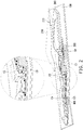
- FIG. 2 is a cross-sectional view of the mainboard module of FIG. 1 along section line A-A'.
- FIG. 3 is an exploded view of the heat dissipation assembly of FIG. 1 . It is to be noted that a case 210 in FIG. 1 and FIG. 2 is shown by a broken line in order to clearly show the internal structure.
- an embodiment of the invention includes a mainboard module 10.
- the mainboard module 10 includes a mainboard 100, a heat dissipation assembly 200, a first heat source 300 ( FIG. 2 ), and a second heat source 400 ( FIG. 2 ).
- the first heat source 300 and the second heat source 400 are disposed on the mainboard 100, and the heat dissipation assembly 200 is adapted to be connected to the mainboard and dissipate heat from the first heat source 300 and the second heat source 400.
- the mainboard 100 may include a central processor (CPU) of a computer, a memory, a southbridge chip, a northbridge chip, and a graphics chip.
- CPU central processor
- the heat dissipation assembly 200 is disposed on the mainboard 100. As shown in FIG. 3 , the heat dissipation assembly 200 includes a case 210 and a partition structure 220.
- the case 210 includes a cavity 211, a first water hole 212, and a second water hole 213, wherein the cavity 211 includes a first region 211a and a second region 211b communicated with each other, and the first water hole 212 and the second water hole 213 are communicated with the first region 211a of the cavity 211. Due to the fluid pressure difference, a fluid is adapted to flow from the first water hole 212 or the second water hole 213 into the cavity 211, and the fluid flows out from the other water hole which has no fluid inflow so as to have less fluid pressure.
- the cavity 211 of the case 210 of the heat dissipation assembly 200 may correspondingly have a narrow or curved variation to give way to the elements on the mainboard 100.
- the cavity 211 of the case 210 may also have the same width on different regions, and is not limited thereto.
- the case 210 is disposed at the first heat source 300 at a portion corresponding to the first region 211a ( FIG. 3 ), and the case 210 is disposed at the second heat source 400 at a portion corresponding to the second region 211b ( FIG. 3 ).
- the first heat source 300 is, for example, a central processor with higher computing efficiency, a northbridge chip, or an integrated chip of a northbridge chip and a central processor
- the second heat source 400 is, for example, a peripheral device interface, a multimedia controller, a communication interface, or a southbridge chip integrated from the above that performs low-speed signal processing.
- the first heat source 300 since the first heat source 300 is larger in size, in the cross-sectional view of FIG. 2 , the first heat source 300 has a larger thickness than the second heat source 400 in the thickness direction of the heat dissipation assembly 200 and the mainboard 100.
- the heat dissipation assembly 200 is attached to the mainboard 100 for enhancing the heat dissipation capability, so that there is a height difference between the first region 211a and the second region 211b of the cavity 211 in order for the case 210 of the heat dissipation assembly 200 to match the height of different positions on the mainboard 100.
- a fin 50 is disposed in a portion in the first region 211a of the cavity 211 corresponding to the first heat source 300 to enhance heat dissipation efficiency.
- the heat dissipation assembly 200 has the partition structure 220 in order to enable the fluid to smoothly remove the heat of the first heat source 300 and the second heat source 400.
- the partition structure 220 includes a separation wall 221 and a separation layer 222 connected to each other, wherein the separation wall 221 is vertically disposed in the first region 211a of the cavity 211 to separate a first flow path C1 and a second flow path C2 disposed in the left and right portions in the first region 221a, and the separation layer 222 is horizontally disposed in the second region 211b of the cavity 211 to separate a third flow path C3 and a fourth flow path C4 disposed in the upper and lower portions in the second region 221b.
- the first flow path C1 is communicated with the third flow path C3, the third flow path C3 is communicated with the fourth flow path C4, and the fourth flow path C4 is communicated with the second flow path C2.
- the separation wall 221 is disposed in a portion of the first region 211a, and the separation wall 221 is extended from a side of the fin 50 upward to the top of the case 210 to absolutely separate the first flow path C1 and the second flow path C2 to prevent fluid from flowing toward the second region 211b from the first flow path C1 and the second flow path C2 simultaneously.
- the first water hole 212 is adjacent to the first flow path C1 and the first heat source 300 beside the separation wall 221, and the second water hole 213 is away from the separation wall 221 and the first heat source 300 to enhance flowing tendency of fluid. For example, a portion of the fluid flowing in from the first water hole 212 tends to flow into the second region 211b from the first flow path C1 due to being adjacent to the first flow path C1.
- the unmarked dashed arrows may be considered as the flow direction of the fluid in the cavity 211.
- the fluid flows in from the first water hole 212, the fluid flows into a hole H located above the fin 50 and comes in contact with the fin 50, and absorbs the heat of the first heat source 300 via the fin 50.
- Fluid injection pressure exists in the first water hole 212 used as the water inlet, but the fluid pressure in the second water hole 213 is less since the second water hole 213 is the water outlet.
- a portion of the fluid flows directly toward the second water hole 213 in the first region 211a after passing through the fin 50 and directly carries a portion of the heat to flow out of the case 210.
- Another part of the fluid flows into the first flow path C1 due to being adjacent to the first flow path C1.
- the pressure of the second flow path C2 is less, and the first flow path C1 is adjacent to the first water hole 212, so that the pressure of the first flow path C1 is greater. Therefore, in the present embodiment, the fluid entering the first flow path C1 automatically flows to the second flow path C2 along the third flow path C3 and the fourth flow path C4 due to the pressure difference. That is, the fluid flowing into the first flow path C1 flows into the third flow path C3 of the second region 211b having less fluid pressure in the cavity 211 due to the influence of the pressure difference.
- the third flow path C3 in the second region 211b is located below the fourth flow path C4 and adjacent to the second heat source 400. Therefore, the second heat source 400 in contact with the case 210 transfers heat to the fluid when the fluid flows through the third flow path C3 to achieve heat exchange of the heat generated by the second heat source 400 to the heat dissipation assembly 200 so as to dissipate heat from the second heat source 400.
- the fluid flows into the fourth flow path C4 via an opening O ( FIG. 1 ) between the third flow path C3 and the fourth flow path C4. It should be noted that the opening O should not be too small to avoid the flow resistance of the fluid from being too large and interfering with fluid flow.
- the fluid flows into the second flow path C2 of the first region 211a communicated with the fourth flow path C4 and flows toward the second water hole 213 having less fluid pressure to carry another portion of the fluid out of the case 210. At this point, the fluid completes the flow path in the heat dissipation assembly 200 in the present embodiment.
- the first water hole 212 and the second water hole 213 generally have tubes communicated with each other outside the case 210, and a condenser (not shown) and a pump (not shown) are installed to the tubes connected to the first water hole 212 and the second water hole 213 and outside the case 210.
- the fluid causes an increase in temperature when flowing through the first heat source 300 or the second heat source 400, and comes in contact with the condenser (not shown) after flowing out of the second water hole 213 to perform heat exchange to lower the fluid temperature, and the pressure of the fluid is increased by the pump (not shown) to pump the fluid into the first water hole 212.
- the circulation of the fluid is achieved to dissipate heat from the mainboard 100.
- FIG. 4 is a schematic view of a fluid direction when a fluid in the heat dissipation assembly of FIG. 1 flows in from the second water hole and flows out of the first water hole.
- the configuration between the remaining structures is not different except that the fluid flow direction is different from that of the embodiment of FIG. 1 , and details are not repeated herein.
- the unmarked dashed arrows may be considered as the flow direction of the fluid in the cavity 211.
- the fluid flows in from the second water hole 213, and a portion of the fluid flows toward the fin 50 below the first water hole 212 in the first region 211a and then directly flows toward the first water hole 212 having less fluid pressure than the second water hole 213 to firstly carry a portion of the heat absorbed by the fluid out of the case 210. Another portion of the fluid flows into the second flow path C2 that is more adjacent to the second water hole 213.
- the first flow path C1 is more adjacent to the first water hole 212 (water outlet hole) than the second flow path C2, the pressure of the first flow path C1 is less, and the second flow path C2 is adjacent to the second water hole 213 (water inlet hole), so that the pressure of the second flow path C2 is greater. Therefore, in the present embodiment, the fluid entering the second flow path C2 automatically flows to the first flow path C1 along the fourth flow path C4 and the third flow path C3 due to the pressure difference.
- the fluid entering the second flow path C2 flows into the fourth flow path C4 of the second region 211b having less fluid pressure in the cavity 211. Then, the fluid flows into the third flow path C3 located below the fourth flow path C4 via the opening O between the fourth flow path C4 and the third flow path C3. Finally, the fluid flows into the first flow path C1 of the first region 211a communicated with the third flow path C3 and flows toward the first water hole 212 having less fluid pressure to carry another portion of the fluid out of the case 210.
- FIG. 5 is a schematic view of the arrangement relationship of the plurality of flow paths of FIG. 1 .
- the partition structure 220 further includes a first baffle B1 and a second baffle B2.
- the first baffle B1 is located between the first flow path C1 and the fourth flow path C4 to block the first flow path C1 and the fourth flow path C4.
- the second baffle B2 is located between the second flow path C2 and the third flow path C3 to block the second flow path C2 and the third flow path C3.
- the first baffle B1 and the second baffle B2 are both respectively in contact with the separation wall 211 and the separation layer 222, and are connected to the case 210.
- the purpose is to prevent the fluid from flowing into the incorrect flow path in a plurality of flow paths.
- the fluid flowing in from the first water hole 212 may only flow toward the direction of the third flow path C3 when flowing in from the first flow path C1 due to the blocking of the first baffle B1 and does not cross the separation layer 222 to directly flow toward the direction of the fourth flow path C4. In this way, the flowing direction of the fluid is ensured.
- FIG. 6 is a schematic diagram of the arrangement relationship of a plurality of flow paths of another embodiment of the invention. The difference from FIG. 5 is that the arrangement positions of the two baffles of FIG. 6 are different, and the arrangements of the remaining elements are all the same as those of FIG. 5 and are not repeated herein.
- a third flow path C3' is defined to be located above a fourth flow path C4'.
- a first baffle B1' is located between the first flow path C1' and the fourth flow path C4'
- a second baffle B2' is located between the second flow path C2' and the third flow path C3'. This configuration limits the flow of the fluid.
- the fluid may only flow through the first flow path C1', the third flow path C3', the fourth flow path C4', and the second flow path C2' in the order indicated by the arrow.
- the fluid may also flow through the second flow path C2', the fourth flow path C4', the third flow path C3', and the first flow path C1' along the direction opposite to the arrow.
- the liquid may enter and exit the heat dissipation assembly via the first water hole and the second water hole of the case, and the cavity is separated into a plurality of flow paths via the partition structure to determine the direction of fluid flow.
- the space of the first region may be separated into the first flow path and the second flow path disposed in the left and right portions via the separation wall of the partition structure, and the space of the second region may be separated into the third flow path and the fourth flow path disposed in the upper and lower portions via the separation layer of the partition structure.
- the cooling fluid may flow through the upper and lower flow paths (or lower and upper flow paths) from one of the left and right flow paths and return to the other of the left and right flow paths when flowing through the second region from the first region and returning to the first region.
- the fluid has pressure differences at various portions in the heat dissipation assembly so that the liquid flows smoothly in the heat dissipation assembly, and the fluid flows through the heat sources on the mainboard to remove the heat generated by the heat sources.
Landscapes
- Engineering & Computer Science (AREA)
- Physics & Mathematics (AREA)
- Thermal Sciences (AREA)
- General Engineering & Computer Science (AREA)
- Microelectronics & Electronic Packaging (AREA)
- Theoretical Computer Science (AREA)
- Mechanical Engineering (AREA)
- Human Computer Interaction (AREA)
- General Physics & Mathematics (AREA)
- Cooling Or The Like Of Electrical Apparatus (AREA)
- Cooling Or The Like Of Semiconductors Or Solid State Devices (AREA)
Abstract
Description
- The invention relates to a heat dissipation assembly, and more particularly, to a heat dissipation assembly applied to a mainboard module.
- Today's computer gamers focus on good computer performance, and high-performance computer parts require higher power consumption. In a high-speed computing environment, the operating temperature of high-power consuming computer parts is increased, thus affecting the operational fluency of the computer system. The current common method of heat dissipation is to use a water-cooled heat dissipation assembly. The heat dissipation assembly mainly absorbs the heat energy of the heat source (such as a central processor, or a display chip of a mainboard), and then discharges the heat-absorbing liquid for heat exchange cooling, and dissipates heat via this cycle. Existing water-cooled heat dissipation assemblies are typically limited by the space constraints of the heat source and may only dissipate heat for a single heat source.
- The invention provides a heat dissipation assembly that dissipates heat from a plurality of heat sources.
- A heat dissipation assembly of the invention includes a case and a separation structure. The case includes a cavity, a first water hole, and a second water hole, wherein the cavity includes a first region and a second region communicated with each other. The first water hole and the second water hole are communicated with the first region of the cavity. The partition structure includes a separation wall and a separation layer connected to each other, wherein the separation wall is vertically disposed in the first region of the cavity to separate a first flow path and a second flow path disposed in the left and right portions in the first region. The separation layer is horizontally disposed in the second region of the cavity to separate a third flow path and a fourth flow path disposed in upper and lower portions of the second region, wherein the first flow path is communicated with the third flow path, the third flow path is communicated with the fourth flow path, and the fourth flow path is communicated with the second flow path.
- In an embodiment of the invention, the separation wall is disposed in a portion of the first region. The first water hole is adjacent to the first flow path beside the separation wall. The second water hole is away from the separation wall.
- In an embodiment of the invention, the third flow path is located below the fourth flow path in the second region.
- In an embodiment of the invention, the third flow path is located above the fourth flow path in the second region.
- In an embodiment of the invention, the first region and the second region of the case have a height difference.
- In an embodiment of the invention, the partition structure further includes two baffles, wherein one of the baffles is located between the first flow path and the fourth flow path to block the first flow path and the fourth flow path, and the other baffle is located between the second flow path and the third flow path to block the second flow path and the third flow path.
- A mainboard module of the invention includes a mainboard, a first heat source disposed on the mainboard, a second heat source disposed on the mainboard, and a heat dissipation assembly. The heat dissipation assembly includes a case and a partition structure. The case includes a cavity, a first water hole, and a second water hole, wherein the cavity includes a first region and a second region communicated with each other. The first water hole and the second water hole are communicated with the first region of the cavity. The case is disposed at the first heat source at a portion corresponding to the first region, and the case is disposed at the second heat source at a portion corresponding to the second region. The partition structure includes a separation wall and a separation layer connected to each other, wherein the separation wall is vertically disposed in the first region of the cavity to separate a first flow path and a second flow path disposed in left and right portions in the first region. The separation layer is horizontally disposed in the second region of the cavity to separate a third flow path and a fourth flow path disposed in upper and lower portions in the second region. The first flow path is communicated with the third flow path, the third flow path is communicated with the fourth flow path, and the fourth flow path is communicated with the second flow path.
- In an embodiment of the invention, the separation wall is disposed in a portion of the first region. The first water hole is adjacent to the first flow path and the first heat source beside the separation wall. The second water hole is away from the separation wall and the first heat source.
- In an embodiment of the invention, the third flow path is located below the fourth flow path in the second region.
- In an embodiment of the invention, the third flow path is located above the fourth flow path in the second region.
- In an embodiment of the invention, the first region and the second region of the case have a height difference.
- In an embodiment of the invention, the partition structure further includes two baffles, wherein one of the baffles is located between the first flow path and the fourth flow path to block the first flow path and the fourth flow path, and the other baffle is located between the second flow path and the third flow path to block the second flow path and the third flow path.
- Based on the above, in the heat dissipation assembly in an embodiment of the invention, the space of the first region may be separated into the first flow path and the second flow path disposed in the left and right portions via the separation wall of the partition structure, and the space of the second region may be separated into the third flow path and the fourth flow path disposed in the upper and lower portions via the separation layer of the partition structure. Moreover, since the first flow path is communicated with the third flow path, the third flow path is communicated with the fourth flow path, and the fourth flow path is communicated with the second flow path, the cooling fluid may flow through the upper and lower flow paths (or lower and upper flow paths) from one of the left and right flow paths and return to the other of the left and right flow paths when flowing through the second region from the first region and returning to the first region. The heat dissipation assembly in an embodiment of the invention is adapted to dissipate heat from two heat sources, wherein one of the heat sources is adapted to be disposed at a location corresponding to the first region on the case, and the other heat source is adapted to be disposed at a location corresponding to the second region on the case to allow the cooling fluid to dissipate heat from the two heat sources on the mainboard when flowing through the first region and the second region to improve the heat dissipation capability of the heat dissipation assembly to the electronic device.
- In order to make the aforementioned features and advantages of the disclosure more comprehensible, embodiments accompanied with figures are described in detail below.
- The accompanying drawings are included to provide a further understanding of the invention, and are incorporated in and constitute a part of this specification. The drawings illustrate embodiments of the invention and, together with the description, serve to explain the principles of the invention.
-
FIG. 1 is a perspective view of the exterior of a mainboard module of an embodiment of the invention. -
FIG. 2 is a cross-sectional view of the mainboard module ofFIG. 1 along section line A-A'. -
FIG. 3 is an exploded view of the heat dissipation assembly ofFIG. 1 . -
FIG. 4 is a schematic view of a fluid direction when a fluid in the heat dissipation assembly ofFIG. 1 flows in from the second water hole and flows out of the first water hole. -
FIG. 5 is a schematic view of the arrangement relationship of the plurality of flow paths ofFIG. 1 andFIG. 4 . -
FIG. 6 is a schematic diagram of the arrangement relationship of a plurality of flow paths of another embodiment of the invention. -
FIG. 1 is a perspective view of the exterior of a mainboard module of an embodiment of the invention.FIG. 2 is a cross-sectional view of the mainboard module ofFIG. 1 along section line A-A'.FIG. 3 is an exploded view of the heat dissipation assembly ofFIG. 1 . It is to be noted that acase 210 inFIG. 1 andFIG. 2 is shown by a broken line in order to clearly show the internal structure. - Referring to
FIG. 1 to FIG. 3 , an embodiment of the invention includes amainboard module 10. Themainboard module 10 includes amainboard 100, aheat dissipation assembly 200, a first heat source 300 (FIG. 2 ), and a second heat source 400 (FIG. 2 ). In the present embodiment, thefirst heat source 300 and thesecond heat source 400 are disposed on themainboard 100, and theheat dissipation assembly 200 is adapted to be connected to the mainboard and dissipate heat from thefirst heat source 300 and thesecond heat source 400. In the present embodiment, themainboard 100 may include a central processor (CPU) of a computer, a memory, a southbridge chip, a northbridge chip, and a graphics chip. - The
heat dissipation assembly 200 is disposed on themainboard 100. As shown inFIG. 3 , theheat dissipation assembly 200 includes acase 210 and apartition structure 220. Thecase 210 includes acavity 211, afirst water hole 212, and asecond water hole 213, wherein thecavity 211 includes afirst region 211a and asecond region 211b communicated with each other, and thefirst water hole 212 and thesecond water hole 213 are communicated with thefirst region 211a of thecavity 211. Due to the fluid pressure difference, a fluid is adapted to flow from thefirst water hole 212 or thesecond water hole 213 into thecavity 211, and the fluid flows out from the other water hole which has no fluid inflow so as to have less fluid pressure. - In addition, in the present embodiment, since there are many elements (not shown) on the
mainboard 100, as may be seen fromFIG. 3 , thecavity 211 of thecase 210 of theheat dissipation assembly 200 may correspondingly have a narrow or curved variation to give way to the elements on themainboard 100. Of course, in other embodiments, thecavity 211 of thecase 210 may also have the same width on different regions, and is not limited thereto. - As shown in
FIG. 2 , thecase 210 is disposed at thefirst heat source 300 at a portion corresponding to thefirst region 211a (FIG. 3 ), and thecase 210 is disposed at thesecond heat source 400 at a portion corresponding to thesecond region 211b (FIG. 3 ). In the present embodiment, thefirst heat source 300 is, for example, a central processor with higher computing efficiency, a northbridge chip, or an integrated chip of a northbridge chip and a central processor, and thesecond heat source 400 is, for example, a peripheral device interface, a multimedia controller, a communication interface, or a southbridge chip integrated from the above that performs low-speed signal processing. In addition, in the present embodiment, since thefirst heat source 300 is larger in size, in the cross-sectional view ofFIG. 2 , thefirst heat source 300 has a larger thickness than thesecond heat source 400 in the thickness direction of theheat dissipation assembly 200 and themainboard 100. In some embodiments, theheat dissipation assembly 200 is attached to themainboard 100 for enhancing the heat dissipation capability, so that there is a height difference between thefirst region 211a and thesecond region 211b of thecavity 211 in order for thecase 210 of theheat dissipation assembly 200 to match the height of different positions on themainboard 100. - In addition, in the present embodiment, since the heat generated by the
first heat source 300 is larger, afin 50 is disposed in a portion in thefirst region 211a of thecavity 211 corresponding to thefirst heat source 300 to enhance heat dissipation efficiency. - In the present embodiment, the
heat dissipation assembly 200 has thepartition structure 220 in order to enable the fluid to smoothly remove the heat of thefirst heat source 300 and thesecond heat source 400. Thepartition structure 220 includes aseparation wall 221 and aseparation layer 222 connected to each other, wherein theseparation wall 221 is vertically disposed in thefirst region 211a of thecavity 211 to separate a first flow path C1 and a second flow path C2 disposed in the left and right portions in the first region 221a, and theseparation layer 222 is horizontally disposed in thesecond region 211b of thecavity 211 to separate a third flow path C3 and a fourth flow path C4 disposed in the upper and lower portions in the second region 221b. The first flow path C1 is communicated with the third flow path C3, the third flow path C3 is communicated with the fourth flow path C4, and the fourth flow path C4 is communicated with the second flow path C2. - Referring to
FIG. 1 to FIG. 3 , in the present embodiment, theseparation wall 221 is disposed in a portion of thefirst region 211a, and theseparation wall 221 is extended from a side of thefin 50 upward to the top of thecase 210 to absolutely separate the first flow path C1 and the second flow path C2 to prevent fluid from flowing toward thesecond region 211b from the first flow path C1 and the second flow path C2 simultaneously. In addition, in the present embodiment, thefirst water hole 212 is adjacent to the first flow path C1 and thefirst heat source 300 beside theseparation wall 221, and thesecond water hole 213 is away from theseparation wall 221 and thefirst heat source 300 to enhance flowing tendency of fluid. For example, a portion of the fluid flowing in from thefirst water hole 212 tends to flow into thesecond region 211b from the first flow path C1 due to being adjacent to the first flow path C1. - In addition to the clearly marked dashed arrows in
FIG. 1 andFIG. 2 , the unmarked dashed arrows may be considered as the flow direction of the fluid in thecavity 211. When the fluid flows in from thefirst water hole 212, the fluid flows into a hole H located above thefin 50 and comes in contact with thefin 50, and absorbs the heat of thefirst heat source 300 via thefin 50. Fluid injection pressure exists in thefirst water hole 212 used as the water inlet, but the fluid pressure in thesecond water hole 213 is less since thesecond water hole 213 is the water outlet. A portion of the fluid flows directly toward thesecond water hole 213 in thefirst region 211a after passing through thefin 50 and directly carries a portion of the heat to flow out of thecase 210. - Another part of the fluid flows into the first flow path C1 due to being adjacent to the first flow path C1. It is to be noted that since the second flow path C2 is more adjacent to the
second water hole 213 than the first flow path C1, the pressure of the second flow path C2 is less, and the first flow path C1 is adjacent to thefirst water hole 212, so that the pressure of the first flow path C1 is greater. Therefore, in the present embodiment, the fluid entering the first flow path C1 automatically flows to the second flow path C2 along the third flow path C3 and the fourth flow path C4 due to the pressure difference. That is, the fluid flowing into the first flow path C1 flows into the third flow path C3 of thesecond region 211b having less fluid pressure in thecavity 211 due to the influence of the pressure difference. - In the present embodiment, the third flow path C3 in the
second region 211b is located below the fourth flow path C4 and adjacent to thesecond heat source 400. Therefore, thesecond heat source 400 in contact with thecase 210 transfers heat to the fluid when the fluid flows through the third flow path C3 to achieve heat exchange of the heat generated by thesecond heat source 400 to theheat dissipation assembly 200 so as to dissipate heat from thesecond heat source 400. - Then, the fluid flows into the fourth flow path C4 via an opening O (
FIG. 1 ) between the third flow path C3 and the fourth flow path C4. It should be noted that the opening O should not be too small to avoid the flow resistance of the fluid from being too large and interfering with fluid flow. Finally, the fluid flows into the second flow path C2 of thefirst region 211a communicated with the fourth flow path C4 and flows toward thesecond water hole 213 having less fluid pressure to carry another portion of the fluid out of thecase 210. At this point, the fluid completes the flow path in theheat dissipation assembly 200 in the present embodiment. - It is worth mentioning that, although not specifically shown, the
first water hole 212 and thesecond water hole 213 generally have tubes communicated with each other outside thecase 210, and a condenser (not shown) and a pump (not shown) are installed to the tubes connected to thefirst water hole 212 and thesecond water hole 213 and outside thecase 210. The fluid causes an increase in temperature when flowing through thefirst heat source 300 or thesecond heat source 400, and comes in contact with the condenser (not shown) after flowing out of thesecond water hole 213 to perform heat exchange to lower the fluid temperature, and the pressure of the fluid is increased by the pump (not shown) to pump the fluid into thefirst water hole 212. Via the above, the circulation of the fluid is achieved to dissipate heat from themainboard 100. - Of course, the flow path of the fluid through the
heat dissipation assembly 200 is not limited thereto.FIG. 4 is a schematic view of a fluid direction when a fluid in the heat dissipation assembly ofFIG. 1 flows in from the second water hole and flows out of the first water hole. Referring toFIG. 4 , in the present embodiment, the configuration between the remaining structures is not different except that the fluid flow direction is different from that of the embodiment ofFIG. 1 , and details are not repeated herein. In addition to the clearly marked dashed arrows inFIG. 4 , the unmarked dashed arrows may be considered as the flow direction of the fluid in thecavity 211. - In
FIG. 4 , the fluid flows in from thesecond water hole 213, and a portion of the fluid flows toward thefin 50 below thefirst water hole 212 in thefirst region 211a and then directly flows toward thefirst water hole 212 having less fluid pressure than thesecond water hole 213 to firstly carry a portion of the heat absorbed by the fluid out of thecase 210. Another portion of the fluid flows into the second flow path C2 that is more adjacent to thesecond water hole 213. It should be noted that, in the present embodiment, since the first flow path C1 is more adjacent to the first water hole 212 (water outlet hole) than the second flow path C2, the pressure of the first flow path C1 is less, and the second flow path C2 is adjacent to the second water hole 213 (water inlet hole), so that the pressure of the second flow path C2 is greater. Therefore, in the present embodiment, the fluid entering the second flow path C2 automatically flows to the first flow path C1 along the fourth flow path C4 and the third flow path C3 due to the pressure difference. - That is, the fluid entering the second flow path C2 flows into the fourth flow path C4 of the
second region 211b having less fluid pressure in thecavity 211. Then, the fluid flows into the third flow path C3 located below the fourth flow path C4 via the opening O between the fourth flow path C4 and the third flow path C3. Finally, the fluid flows into the first flow path C1 of thefirst region 211a communicated with the third flow path C3 and flows toward thefirst water hole 212 having less fluid pressure to carry another portion of the fluid out of thecase 210. - It is worth mentioning that in the above embodiment, there is a height difference between the
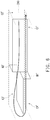
first region 211a and thesecond region 211b of thecase 210, but thefirst region 211a and thesecond region 211b may also be located at the same height.FIG. 5 is a schematic view of the arrangement relationship of the plurality of flow paths ofFIG. 1 . Referring toFIG. 5 , thepartition structure 220 further includes a first baffle B1 and a second baffle B2. The first baffle B1 is located between the first flow path C1 and the fourth flow path C4 to block the first flow path C1 and the fourth flow path C4. The second baffle B2 is located between the second flow path C2 and the third flow path C3 to block the second flow path C2 and the third flow path C3. The first baffle B1 and the second baffle B2 are both respectively in contact with theseparation wall 211 and theseparation layer 222, and are connected to thecase 210. The purpose is to prevent the fluid from flowing into the incorrect flow path in a plurality of flow paths. For example, the fluid flowing in from thefirst water hole 212 may only flow toward the direction of the third flow path C3 when flowing in from the first flow path C1 due to the blocking of the first baffle B1 and does not cross theseparation layer 222 to directly flow toward the direction of the fourth flow path C4. In this way, the flowing direction of the fluid is ensured. - Of course, the configuration of the baffle is not limited thereto.
FIG. 6 is a schematic diagram of the arrangement relationship of a plurality of flow paths of another embodiment of the invention. The difference fromFIG. 5 is that the arrangement positions of the two baffles ofFIG. 6 are different, and the arrangements of the remaining elements are all the same as those ofFIG. 5 and are not repeated herein. Referring toFIG. 6 , in the present embodiment, a third flow path C3' is defined to be located above a fourth flow path C4'. A first baffle B1' is located between the first flow path C1' and the fourth flow path C4', and a second baffle B2' is located between the second flow path C2' and the third flow path C3'. This configuration limits the flow of the fluid. The fluid may only flow through the first flow path C1', the third flow path C3', the fourth flow path C4', and the second flow path C2' in the order indicated by the arrow. Of course, if the user adjusts the flow direction of the fluid, the fluid may also flow through the second flow path C2', the fourth flow path C4', the third flow path C3', and the first flow path C1' along the direction opposite to the arrow. - Based on the above, in the mainboard module of an embodiment of the invention, the liquid may enter and exit the heat dissipation assembly via the first water hole and the second water hole of the case, and the cavity is separated into a plurality of flow paths via the partition structure to determine the direction of fluid flow. In the heat dissipation assembly in an embodiment of the invention, the space of the first region may be separated into the first flow path and the second flow path disposed in the left and right portions via the separation wall of the partition structure, and the space of the second region may be separated into the third flow path and the fourth flow path disposed in the upper and lower portions via the separation layer of the partition structure. Moreover, since the first flow path is communicated with the third flow path, the third flow path is communicated with the fourth flow path, and the fourth flow path is communicated with the second flow path, the cooling fluid may flow through the upper and lower flow paths (or lower and upper flow paths) from one of the left and right flow paths and return to the other of the left and right flow paths when flowing through the second region from the first region and returning to the first region. The fluid has pressure differences at various portions in the heat dissipation assembly so that the liquid flows smoothly in the heat dissipation assembly, and the fluid flows through the heat sources on the mainboard to remove the heat generated by the heat sources.
Claims (12)
- A heat dissipation assembly (200), comprising:a case (210) comprising a cavity (211), a first water hole (212), and a second water hole (213), wherein the cavity (211) comprises a first region (211a) and a second region (211b) communicated with each other, and the first water hole (212) and the second water hole (213) are communicated with the first region (211a) of the cavity (211); anda partition structure (220) comprising a separation wall (221) and a separation layer (222) connected to each other, wherein the separation wall (221) is vertically disposed in the first region (211a) of the cavity (211) to separate a first flow path (C1, C1') and a second flow path (C2, C2') disposed in left and right portions in the first region (211a), and the separation layer (222) is horizontally disposed in the second region (211b) of the cavity (211) to separate a third flow path (C3, C3') and a fourth flow path (C4, C4') disposed in upper and lower portions in the second region (211b), wherein the first flow path (C1, C1') is communicated with the third flow path (C3, C3'), the third flow path (C3, C3') is communicated with the fourth flow path (C4, C4'), and the fourth flow path (C4, C4') is communicated with the second flow path (C2, C2').
- The heat dissipation assembly (200) of claim 1, wherein the separation wall (221) is disposed in a portion of the first region (211a), the first water hole (212) is adjacent to the first flow path (C1, C1') beside the separation wall (221), and the second water hole (213) is away from the separation wall (221).
- The heat dissipation assembly (200) of claim 1, wherein the third flow path (C3, C3') is located below the fourth flow path (C4, C4') in the second region (211b).
- The heat dissipation assembly (200) of claim 1, wherein the third flow path (C3, C3') is located above the fourth flow path (C4, C4') in the second region (211b).
- The heat dissipation assembly (200) of claim 1, wherein the first region (211a) and the second region (211b) of the case (210) have a height difference.
- The heat dissipation assembly (200) of claim 1, wherein the partition structure (220) further comprises two baffles (B1, B1', B2, B2'), wherein one of the baffles (B1, B1', B2, B2') is located between the first flow path (C1, C1') and the fourth flow path (C4, C4') to block the first flow path (C1, C1') and the fourth flow path (C4, C4'), and the other baffle (B1, B1', B2, B2') is located between the second flow path (C2, C2') and the third flow path (C3, C3') to block the second flow path (C2, C2') and the third flow path (C3, C3').
- A mainboard module (10), comprising:a mainboard (100);a first heat source (300) disposed on the mainboard (100);a second heat source (400) disposed on the mainboard (100); anda heat dissipation assembly (200), comprising:a case (210) comprising a cavity (211), a first water hole (212), and a second water hole (213), wherein the cavity (211) comprises a first region (211a) and a second region (211b) communicated with each other, the first water hole (212) and the second water hole (213) are communicated with the first region (211a) of the cavity (211), the case (210) is disposed at the first heat source (300) at a portion corresponding to the first region (211a), and the case (210) is disposed at the second heat source (400) at a portion corresponding to the second region (211b); anda partition structure (220) comprising a separation wall (221) and a separation layer (222) connected to each other, wherein the separation wall (221) is vertically disposed in the first region (211a) of the cavity (211) to separate a first flow path (C1, C1') and a second flow path (C2, C2') disposed in left and right portions in the first region (211a), and the separation layer (222) is horizontally disposed in the second region (211b) of the cavity (211) to separate a third flow path (C3, C3') and a fourth flow path (C4, C4') disposed in upper and lower portions in the second region (211b), wherein the first flow path (C1, C1') is communicated with the third flow path (C3, C3'), the third flow path (C3, C3') is communicated with the fourth flow path (C4, C4'), and the fourth flow path (C4, C4') is communicated with the second flow path (C2, C2').
- The mainboard module (10) of claim 7, wherein the separation wall (221) is disposed in a portion of the first region (211a), the first water hole (212) is adjacent to the first flow path (C1, C1') and the first heat source (300) beside the separation wall (221), and the second water hole (213) is away from the separation wall (221) and the first heat source (300).
- The mainboard module (10) of claim 7, wherein the third flow path (C3, C3') is located below the fourth flow path (C4, C4') in the second region (211b).
- The mainboard module (10) of claim 7, wherein the third flow path (C3, C3') is located above the fourth flow path (C4, C4') in the second region (211b).
- The mainboard module (10) of claim 7, wherein the first region (211a) and the second region (211b) of the case (210) have a height difference.
- The mainboard module (10) of claim 7, wherein the partition structure (220) further comprises two baffles (B1, B1', B2, B2'), wherein one of the baffles (B1, B1', B2, B2') is located between the first flow path (C1, C1') and the fourth flow path (C4, C4') to block the first flow path (C1, C1') and the fourth flow path (C4, C4'), and the other baffle (B1, B1', B2, B2') is located between the second flow path (C2, C2') and the third flow path (C3, C3') to block the second flow path (C2, C2') and the third flow path (C3, C3').
Applications Claiming Priority (1)
| Application Number | Priority Date | Filing Date | Title |
|---|---|---|---|
| TW107137459A TWI673842B (en) | 2018-10-24 | 2018-10-24 | Heat dissipation assembly and mainboard module |
Publications (2)
| Publication Number | Publication Date |
|---|---|
| EP3644159A1 true EP3644159A1 (en) | 2020-04-29 |
| EP3644159B1 EP3644159B1 (en) | 2022-01-12 |
Family
ID=68318822
Family Applications (1)
| Application Number | Title | Priority Date | Filing Date |
|---|---|---|---|
| EP19204320.6A Active EP3644159B1 (en) | 2018-10-24 | 2019-10-21 | Heat dissipation assembly and mainboard module |
Country Status (3)
| Country | Link |
|---|---|
| US (1) | US10973150B2 (en) |
| EP (1) | EP3644159B1 (en) |
| TW (1) | TWI673842B (en) |
Families Citing this family (1)
| Publication number | Priority date | Publication date | Assignee | Title |
|---|---|---|---|---|
| CN114001365B (en) * | 2021-12-31 | 2022-04-05 | 光大环保技术装备(常州)有限公司 | Water-cooling runner temperature and flow detection system and method and runner parameter testing system |
Citations (2)
| Publication number | Priority date | Publication date | Assignee | Title |
|---|---|---|---|---|
| US20160126160A1 (en) * | 2014-11-03 | 2016-05-05 | Hyundai Mobis Co., Ltd. | System for cooling dual sides of power semiconductor device |
| TWM568025U (en) * | 2018-05-08 | 2018-10-01 | 大陸商上海綠曜能源科技有限公司 | Leak-detectable liquid-heat-transmission device |
Family Cites Families (18)
| Publication number | Priority date | Publication date | Assignee | Title |
|---|---|---|---|---|
| US4692592A (en) * | 1984-02-23 | 1987-09-08 | Kale Hemant D | Compartmentalized electric liquid heater |
| FR2774215B1 (en) * | 1998-01-29 | 2000-02-25 | Alsthom Cge Alcatel | WATERPROOF MONOBLOCK BATTERY PROVIDED WITH A COOLING DEVICE |
| US7000684B2 (en) * | 2002-11-01 | 2006-02-21 | Cooligy, Inc. | Method and apparatus for efficient vertical fluid delivery for cooling a heat producing device |
| US7156159B2 (en) * | 2003-03-17 | 2007-01-02 | Cooligy, Inc. | Multi-level microchannel heat exchangers |
| US7139172B2 (en) * | 2004-07-01 | 2006-11-21 | International Business Machines Corporation | Apparatus and methods for microchannel cooling of semiconductor integrated circuit packages |
| TW200712421A (en) * | 2005-05-18 | 2007-04-01 | Univ Nat Central | Planar heat dissipating device |
| TW200839495A (en) * | 2007-03-30 | 2008-10-01 | Cooler Master Co Ltd | Structure of water cooling head |
| TW201228570A (en) * | 2010-12-17 | 2012-07-01 | Hon Hai Prec Ind Co Ltd | Liquid heat dissipation device |
| JP5803963B2 (en) * | 2013-03-22 | 2015-11-04 | トヨタ自動車株式会社 | Cooler |
| JP6194700B2 (en) * | 2013-08-30 | 2017-09-13 | 富士通株式会社 | Radiator and method of manufacturing radiator |
| US20160029514A1 (en) * | 2013-12-31 | 2016-01-28 | Aselsan Elektronik Sanayi Ve Ticaret Anonim Sirketi | A liquid cooled device enclosure |
| US9559038B2 (en) * | 2015-04-30 | 2017-01-31 | Deere & Company | Package for a semiconductor device |
| JP6477276B2 (en) * | 2015-06-12 | 2019-03-06 | 富士通株式会社 | Cooling plate and information processing apparatus provided with cooling plate |
| CN106211725A (en) * | 2016-09-05 | 2016-12-07 | 周哲明 | A kind of sealing water-cooled server |
| JP6540665B2 (en) * | 2016-11-21 | 2019-07-10 | トヨタ自動車株式会社 | Double-sided cooler |
| US10847441B2 (en) * | 2017-03-16 | 2020-11-24 | Mitsubishi Electric Corporation | Cooling system |
| DE102018112601A1 (en) * | 2017-05-31 | 2018-12-06 | Hanon Systems | Elektroelement cooling module |
| JP6922612B2 (en) * | 2017-09-27 | 2021-08-18 | 富士通株式会社 | Cooling plate and information processing device |
-
2018
- 2018-10-24 TW TW107137459A patent/TWI673842B/en active
-
2019
- 2019-09-23 US US16/578,424 patent/US10973150B2/en active Active
- 2019-10-21 EP EP19204320.6A patent/EP3644159B1/en active Active
Patent Citations (2)
| Publication number | Priority date | Publication date | Assignee | Title |
|---|---|---|---|---|
| US20160126160A1 (en) * | 2014-11-03 | 2016-05-05 | Hyundai Mobis Co., Ltd. | System for cooling dual sides of power semiconductor device |
| TWM568025U (en) * | 2018-05-08 | 2018-10-01 | 大陸商上海綠曜能源科技有限公司 | Leak-detectable liquid-heat-transmission device |
Also Published As
| Publication number | Publication date |
|---|---|
| TWI673842B (en) | 2019-10-01 |
| US20200137925A1 (en) | 2020-04-30 |
| TW202017128A (en) | 2020-05-01 |
| EP3644159B1 (en) | 2022-01-12 |
| US10973150B2 (en) | 2021-04-06 |
Similar Documents
| Publication | Publication Date | Title |
|---|---|---|
| CN204721777U (en) | Electronic device and liquid cooling type heat dissipation structure thereof | |
| US20220316822A1 (en) | Heat dissipation device and fin structure | |
| US20080128114A1 (en) | Liquid cooling device | |
| TW202006303A (en) | Heat dissipation module | |
| US11943896B2 (en) | Water-cooling radiator | |
| CN201119216Y (en) | Water-cooling head structure of water-cooling type heat dissipation system | |
| TWI851870B (en) | Computer device, case and water cooling device | |
| EP2626899A2 (en) | Heat dissipating module | |
| US20070175610A1 (en) | Heat dissipating device | |
| US10529649B2 (en) | Heat dissipation module | |
| CN110377130A (en) | A kind of water cooling radiator | |
| CN100394352C (en) | cooling jacket | |
| TW201504792A (en) | Cyclic cooling module | |
| US10973150B2 (en) | Heat dissipation assembly and mainboard module | |
| CN109588001B (en) | Dual-circuit liquid cooling system | |
| CN207020624U (en) | Water-cooled heat sink | |
| CN209895295U (en) | A new type of water cooling radiator | |
| CN207321756U (en) | Double loop liquid cooling system | |
| TW202529516A (en) | Gas-liquid dual cooling three-dimensional heat dissipation device | |
| CN111090317B (en) | Heat radiation assembly and motherboard module | |
| CN117270661A (en) | A mini host partitioned heat dissipation structure with a display | |
| CN212061096U (en) | Water Cooling Heatsink and Expansion Card Assembly | |
| CN117666735A (en) | Liquid flow type heat radiator | |
| CN210579811U (en) | Heat sink device | |
| EP3760959B1 (en) | Heat dissipation device |
Legal Events
| Date | Code | Title | Description |
|---|---|---|---|
| PUAI | Public reference made under article 153(3) epc to a published international application that has entered the european phase |
Free format text: ORIGINAL CODE: 0009012 |
|
| STAA | Information on the status of an ep patent application or granted ep patent |
Free format text: STATUS: THE APPLICATION HAS BEEN PUBLISHED |
|
| AK | Designated contracting states |
Kind code of ref document: A1 Designated state(s): AL AT BE BG CH CY CZ DE DK EE ES FI FR GB GR HR HU IE IS IT LI LT LU LV MC MK MT NL NO PL PT RO RS SE SI SK SM TR |
|
| AX | Request for extension of the european patent |
Extension state: BA ME |
|
| STAA | Information on the status of an ep patent application or granted ep patent |
Free format text: STATUS: REQUEST FOR EXAMINATION WAS MADE |
|
| 17P | Request for examination filed |
Effective date: 20201012 |
|
| RBV | Designated contracting states (corrected) |
Designated state(s): AL AT BE BG CH CY CZ DE DK EE ES FI FR GB GR HR HU IE IS IT LI LT LU LV MC MK MT NL NO PL PT RO RS SE SI SK SM TR |
|
| GRAP | Despatch of communication of intention to grant a patent |
Free format text: ORIGINAL CODE: EPIDOSNIGR1 |
|
| STAA | Information on the status of an ep patent application or granted ep patent |
Free format text: STATUS: GRANT OF PATENT IS INTENDED |
|
| INTG | Intention to grant announced |
Effective date: 20210504 |
|
| GRAJ | Information related to disapproval of communication of intention to grant by the applicant or resumption of examination proceedings by the epo deleted |
Free format text: ORIGINAL CODE: EPIDOSDIGR1 |
|
| STAA | Information on the status of an ep patent application or granted ep patent |
Free format text: STATUS: REQUEST FOR EXAMINATION WAS MADE |
|
| INTC | Intention to grant announced (deleted) | ||
| GRAP | Despatch of communication of intention to grant a patent |
Free format text: ORIGINAL CODE: EPIDOSNIGR1 |
|
| STAA | Information on the status of an ep patent application or granted ep patent |
Free format text: STATUS: GRANT OF PATENT IS INTENDED |
|
| INTG | Intention to grant announced |
Effective date: 20210929 |
|
| GRAS | Grant fee paid |
Free format text: ORIGINAL CODE: EPIDOSNIGR3 |
|
| GRAA | (expected) grant |
Free format text: ORIGINAL CODE: 0009210 |
|
| STAA | Information on the status of an ep patent application or granted ep patent |
Free format text: STATUS: THE PATENT HAS BEEN GRANTED |
|
| AK | Designated contracting states |
Kind code of ref document: B1 Designated state(s): AL AT BE BG CH CY CZ DE DK EE ES FI FR GB GR HR HU IE IS IT LI LT LU LV MC MK MT NL NO PL PT RO RS SE SI SK SM TR |
|
| REG | Reference to a national code |
Ref country code: GB Ref legal event code: FG4D |
|
| REG | Reference to a national code |
Ref country code: CH Ref legal event code: EP |
|
| REG | Reference to a national code |
Ref country code: IE Ref legal event code: FG4D |
|
| REG | Reference to a national code |
Ref country code: DE Ref legal event code: R096 Ref document number: 602019010848 Country of ref document: DE |
|
| REG | Reference to a national code |
Ref country code: AT Ref legal event code: REF Ref document number: 1462815 Country of ref document: AT Kind code of ref document: T Effective date: 20220215 |
|
| REG | Reference to a national code |
Ref country code: LT Ref legal event code: MG9D |
|
| REG | Reference to a national code |
Ref country code: NL Ref legal event code: MP Effective date: 20220112 |
|
| REG | Reference to a national code |
Ref country code: AT Ref legal event code: MK05 Ref document number: 1462815 Country of ref document: AT Kind code of ref document: T Effective date: 20220112 |
|
| PG25 | Lapsed in a contracting state [announced via postgrant information from national office to epo] |
Ref country code: NL Free format text: LAPSE BECAUSE OF FAILURE TO SUBMIT A TRANSLATION OF THE DESCRIPTION OR TO PAY THE FEE WITHIN THE PRESCRIBED TIME-LIMIT Effective date: 20220112 |
|
| PG25 | Lapsed in a contracting state [announced via postgrant information from national office to epo] |
Ref country code: SE Free format text: LAPSE BECAUSE OF FAILURE TO SUBMIT A TRANSLATION OF THE DESCRIPTION OR TO PAY THE FEE WITHIN THE PRESCRIBED TIME-LIMIT Effective date: 20220112 Ref country code: RS Free format text: LAPSE BECAUSE OF FAILURE TO SUBMIT A TRANSLATION OF THE DESCRIPTION OR TO PAY THE FEE WITHIN THE PRESCRIBED TIME-LIMIT Effective date: 20220112 Ref country code: PT Free format text: LAPSE BECAUSE OF FAILURE TO SUBMIT A TRANSLATION OF THE DESCRIPTION OR TO PAY THE FEE WITHIN THE PRESCRIBED TIME-LIMIT Effective date: 20220512 Ref country code: NO Free format text: LAPSE BECAUSE OF FAILURE TO SUBMIT A TRANSLATION OF THE DESCRIPTION OR TO PAY THE FEE WITHIN THE PRESCRIBED TIME-LIMIT Effective date: 20220412 Ref country code: LT Free format text: LAPSE BECAUSE OF FAILURE TO SUBMIT A TRANSLATION OF THE DESCRIPTION OR TO PAY THE FEE WITHIN THE PRESCRIBED TIME-LIMIT Effective date: 20220112 Ref country code: HR Free format text: LAPSE BECAUSE OF FAILURE TO SUBMIT A TRANSLATION OF THE DESCRIPTION OR TO PAY THE FEE WITHIN THE PRESCRIBED TIME-LIMIT Effective date: 20220112 Ref country code: ES Free format text: LAPSE BECAUSE OF FAILURE TO SUBMIT A TRANSLATION OF THE DESCRIPTION OR TO PAY THE FEE WITHIN THE PRESCRIBED TIME-LIMIT Effective date: 20220112 Ref country code: BG Free format text: LAPSE BECAUSE OF FAILURE TO SUBMIT A TRANSLATION OF THE DESCRIPTION OR TO PAY THE FEE WITHIN THE PRESCRIBED TIME-LIMIT Effective date: 20220412 |
|
| PG25 | Lapsed in a contracting state [announced via postgrant information from national office to epo] |
Ref country code: PL Free format text: LAPSE BECAUSE OF FAILURE TO SUBMIT A TRANSLATION OF THE DESCRIPTION OR TO PAY THE FEE WITHIN THE PRESCRIBED TIME-LIMIT Effective date: 20220112 Ref country code: LV Free format text: LAPSE BECAUSE OF FAILURE TO SUBMIT A TRANSLATION OF THE DESCRIPTION OR TO PAY THE FEE WITHIN THE PRESCRIBED TIME-LIMIT Effective date: 20220112 Ref country code: GR Free format text: LAPSE BECAUSE OF FAILURE TO SUBMIT A TRANSLATION OF THE DESCRIPTION OR TO PAY THE FEE WITHIN THE PRESCRIBED TIME-LIMIT Effective date: 20220413 Ref country code: FI Free format text: LAPSE BECAUSE OF FAILURE TO SUBMIT A TRANSLATION OF THE DESCRIPTION OR TO PAY THE FEE WITHIN THE PRESCRIBED TIME-LIMIT Effective date: 20220112 Ref country code: AT Free format text: LAPSE BECAUSE OF FAILURE TO SUBMIT A TRANSLATION OF THE DESCRIPTION OR TO PAY THE FEE WITHIN THE PRESCRIBED TIME-LIMIT Effective date: 20220112 |
|
| PG25 | Lapsed in a contracting state [announced via postgrant information from national office to epo] |
Ref country code: IS Free format text: LAPSE BECAUSE OF FAILURE TO SUBMIT A TRANSLATION OF THE DESCRIPTION OR TO PAY THE FEE WITHIN THE PRESCRIBED TIME-LIMIT Effective date: 20220512 |
|
| REG | Reference to a national code |
Ref country code: DE Ref legal event code: R097 Ref document number: 602019010848 Country of ref document: DE |
|
| PG25 | Lapsed in a contracting state [announced via postgrant information from national office to epo] |
Ref country code: SM Free format text: LAPSE BECAUSE OF FAILURE TO SUBMIT A TRANSLATION OF THE DESCRIPTION OR TO PAY THE FEE WITHIN THE PRESCRIBED TIME-LIMIT Effective date: 20220112 Ref country code: SK Free format text: LAPSE BECAUSE OF FAILURE TO SUBMIT A TRANSLATION OF THE DESCRIPTION OR TO PAY THE FEE WITHIN THE PRESCRIBED TIME-LIMIT Effective date: 20220112 Ref country code: RO Free format text: LAPSE BECAUSE OF FAILURE TO SUBMIT A TRANSLATION OF THE DESCRIPTION OR TO PAY THE FEE WITHIN THE PRESCRIBED TIME-LIMIT Effective date: 20220112 Ref country code: EE Free format text: LAPSE BECAUSE OF FAILURE TO SUBMIT A TRANSLATION OF THE DESCRIPTION OR TO PAY THE FEE WITHIN THE PRESCRIBED TIME-LIMIT Effective date: 20220112 Ref country code: DK Free format text: LAPSE BECAUSE OF FAILURE TO SUBMIT A TRANSLATION OF THE DESCRIPTION OR TO PAY THE FEE WITHIN THE PRESCRIBED TIME-LIMIT Effective date: 20220112 Ref country code: CZ Free format text: LAPSE BECAUSE OF FAILURE TO SUBMIT A TRANSLATION OF THE DESCRIPTION OR TO PAY THE FEE WITHIN THE PRESCRIBED TIME-LIMIT Effective date: 20220112 |
|
| PLBE | No opposition filed within time limit |
Free format text: ORIGINAL CODE: 0009261 |
|
| STAA | Information on the status of an ep patent application or granted ep patent |
Free format text: STATUS: NO OPPOSITION FILED WITHIN TIME LIMIT |
|
| PG25 | Lapsed in a contracting state [announced via postgrant information from national office to epo] |
Ref country code: AL Free format text: LAPSE BECAUSE OF FAILURE TO SUBMIT A TRANSLATION OF THE DESCRIPTION OR TO PAY THE FEE WITHIN THE PRESCRIBED TIME-LIMIT Effective date: 20220112 |
|
| 26N | No opposition filed |
Effective date: 20221013 |
|
| PG25 | Lapsed in a contracting state [announced via postgrant information from national office to epo] |
Ref country code: SI Free format text: LAPSE BECAUSE OF FAILURE TO SUBMIT A TRANSLATION OF THE DESCRIPTION OR TO PAY THE FEE WITHIN THE PRESCRIBED TIME-LIMIT Effective date: 20220112 |
|
| PG25 | Lapsed in a contracting state [announced via postgrant information from national office to epo] |
Ref country code: MC Free format text: LAPSE BECAUSE OF FAILURE TO SUBMIT A TRANSLATION OF THE DESCRIPTION OR TO PAY THE FEE WITHIN THE PRESCRIBED TIME-LIMIT Effective date: 20220112 |
|
| REG | Reference to a national code |
Ref country code: CH Ref legal event code: PL |
|
| REG | Reference to a national code |
Ref country code: BE Ref legal event code: MM Effective date: 20221031 |
|
| PG25 | Lapsed in a contracting state [announced via postgrant information from national office to epo] |
Ref country code: LU Free format text: LAPSE BECAUSE OF NON-PAYMENT OF DUE FEES Effective date: 20221021 |
|
| PG25 | Lapsed in a contracting state [announced via postgrant information from national office to epo] |
Ref country code: LI Free format text: LAPSE BECAUSE OF NON-PAYMENT OF DUE FEES Effective date: 20221031 Ref country code: IT Free format text: LAPSE BECAUSE OF FAILURE TO SUBMIT A TRANSLATION OF THE DESCRIPTION OR TO PAY THE FEE WITHIN THE PRESCRIBED TIME-LIMIT Effective date: 20220112 Ref country code: CH Free format text: LAPSE BECAUSE OF NON-PAYMENT OF DUE FEES Effective date: 20221031 |
|
| PG25 | Lapsed in a contracting state [announced via postgrant information from national office to epo] |
Ref country code: BE Free format text: LAPSE BECAUSE OF NON-PAYMENT OF DUE FEES Effective date: 20221031 |
|
| PG25 | Lapsed in a contracting state [announced via postgrant information from national office to epo] |
Ref country code: IE Free format text: LAPSE BECAUSE OF NON-PAYMENT OF DUE FEES Effective date: 20221021 |
|
| PG25 | Lapsed in a contracting state [announced via postgrant information from national office to epo] |
Ref country code: HU Free format text: LAPSE BECAUSE OF FAILURE TO SUBMIT A TRANSLATION OF THE DESCRIPTION OR TO PAY THE FEE WITHIN THE PRESCRIBED TIME-LIMIT; INVALID AB INITIO Effective date: 20191021 |
|
| PG25 | Lapsed in a contracting state [announced via postgrant information from national office to epo] |
Ref country code: CY Free format text: LAPSE BECAUSE OF FAILURE TO SUBMIT A TRANSLATION OF THE DESCRIPTION OR TO PAY THE FEE WITHIN THE PRESCRIBED TIME-LIMIT Effective date: 20220112 |
|
| PG25 | Lapsed in a contracting state [announced via postgrant information from national office to epo] |
Ref country code: MK Free format text: LAPSE BECAUSE OF FAILURE TO SUBMIT A TRANSLATION OF THE DESCRIPTION OR TO PAY THE FEE WITHIN THE PRESCRIBED TIME-LIMIT Effective date: 20220112 |
|
| PG25 | Lapsed in a contracting state [announced via postgrant information from national office to epo] |
Ref country code: MT Free format text: LAPSE BECAUSE OF FAILURE TO SUBMIT A TRANSLATION OF THE DESCRIPTION OR TO PAY THE FEE WITHIN THE PRESCRIBED TIME-LIMIT Effective date: 20220112 |
|
| PGFP | Annual fee paid to national office [announced via postgrant information from national office to epo] |
Ref country code: GB Payment date: 20250904 Year of fee payment: 7 |
|
| PGFP | Annual fee paid to national office [announced via postgrant information from national office to epo] |
Ref country code: FR Payment date: 20250908 Year of fee payment: 7 |
|
| PG25 | Lapsed in a contracting state [announced via postgrant information from national office to epo] |
Ref country code: TR Free format text: LAPSE BECAUSE OF FAILURE TO SUBMIT A TRANSLATION OF THE DESCRIPTION OR TO PAY THE FEE WITHIN THE PRESCRIBED TIME-LIMIT Effective date: 20220112 |
|
| PGFP | Annual fee paid to national office [announced via postgrant information from national office to epo] |
Ref country code: DE Payment date: 20250902 Year of fee payment: 7 |