CN209895295U - A new type of water cooling radiator - Google Patents
A new type of water cooling radiator Download PDFInfo
- Publication number
- CN209895295U CN209895295U CN201921040740.2U CN201921040740U CN209895295U CN 209895295 U CN209895295 U CN 209895295U CN 201921040740 U CN201921040740 U CN 201921040740U CN 209895295 U CN209895295 U CN 209895295U
- Authority
- CN
- China
- Prior art keywords
- water
- cavity
- heat dissipation
- groove
- plate
- Prior art date
- Legal status (The legal status is an assumption and is not a legal conclusion. Google has not performed a legal analysis and makes no representation as to the accuracy of the status listed.)
- Active
Links
- XLYOFNOQVPJJNP-UHFFFAOYSA-N water Substances O XLYOFNOQVPJJNP-UHFFFAOYSA-N 0.000 title claims abstract description 169
- 238000001816 cooling Methods 0.000 title claims abstract description 17
- 239000007788 liquid Substances 0.000 claims abstract description 53
- 230000017525 heat dissipation Effects 0.000 claims description 40
- 238000007789 sealing Methods 0.000 claims description 21
- 238000010521 absorption reaction Methods 0.000 claims description 13
- 210000000476 body water Anatomy 0.000 claims 1
- 239000000110 cooling liquid Substances 0.000 abstract description 24
- 230000000694 effects Effects 0.000 abstract description 10
- 238000009434 installation Methods 0.000 abstract description 6
- 238000012423 maintenance Methods 0.000 abstract description 5
- 239000002826 coolant Substances 0.000 abstract description 4
- 239000000498 cooling water Substances 0.000 description 7
- XAGFODPZIPBFFR-UHFFFAOYSA-N aluminium Chemical compound [Al] XAGFODPZIPBFFR-UHFFFAOYSA-N 0.000 description 5
- 229910052782 aluminium Inorganic materials 0.000 description 5
- 238000000034 method Methods 0.000 description 5
- 230000004888 barrier function Effects 0.000 description 4
- 238000010586 diagram Methods 0.000 description 4
- 238000011161 development Methods 0.000 description 3
- 238000004891 communication Methods 0.000 description 2
- 238000013461 design Methods 0.000 description 2
- 238000005516 engineering process Methods 0.000 description 2
- 230000009286 beneficial effect Effects 0.000 description 1
- 230000000903 blocking effect Effects 0.000 description 1
- 230000020169 heat generation Effects 0.000 description 1
Images




Landscapes
- Cooling Or The Like Of Electrical Apparatus (AREA)
Abstract
Description
技术领域technical field
本实用新型涉及水冷散热领域,尤指一种新型水冷散热器。The utility model relates to the field of water cooling and heat dissipation, in particular to a novel water cooling radiator.
背景技术Background technique
目前,随着电子科技的快速发展以及人们在生活娱乐和工作上的需要,计算机已经成了人们日常生活中必不可少的一种生活用品。现在人们无论是娱乐还是工作,大多数时候都离不开电脑,而随着电子技术的飞速发展,电脑计算机的性能也有了飞速提高。性能的提高同时也伴随着发热量的增加,对计算机的性能、使用寿命有造成了严重的影响。At present, with the rapid development of electronic technology and people's needs in life, entertainment and work, computers have become an indispensable daily necessities in people's daily life. Nowadays, people are inseparable from computers most of the time, whether for entertainment or work, and with the rapid development of electronic technology, the performance of computers has also been rapidly improved. The improvement of performance is also accompanied by the increase of heat generation, which has a serious impact on the performance and service life of the computer.
现有的散热系统主要有风冷散热系统和水冷散热系统,其中水冷散热系统因其显著的散热性能以及较低的噪音已被大量应用在 CPU 的散热处理上,并且成为计算机冷却系统的重要发展趋势之一。The existing cooling systems mainly include air-cooled cooling systems and water-cooled cooling systems. Among them, water-cooled cooling systems have been widely used in CPU cooling due to their remarkable cooling performance and low noise, and have become an important development in computer cooling systems. one of the trends.
然而,由于现技术中水冷散热系统水路设计单一,其内部的冷却液与散热器件接触面积较少,故容易出现散热效果不佳,散热效率不高的情况出现;而且现在水冷散热器将泵体设置在设备内部,故安装以及维修均十分不便。However, due to the single water circuit design of the water-cooled heat dissipation system in the prior art, the contact area between the cooling liquid inside and the heat sink is small, so the heat dissipation effect is not good and the heat dissipation efficiency is not high. It is installed inside the equipment, so installation and maintenance are very inconvenient.
发明内容SUMMARY OF THE INVENTION
为解决上述问题,本实用新型提供一种新型水冷散热器,保证了冷却液能最大限度地与散热片组中多个散热片接触,增加了冷却液与散热片组的接触面积,提高散热效果;同时本申请的泵体采用外置连接的方式,安装连接更加方便,性能更加优越,而且维修更加便捷。In order to solve the above problems, the utility model provides a new type of water-cooled radiator, which ensures that the cooling liquid can be in contact with a plurality of radiating fins in the radiating fin group to the maximum extent, increases the contact area between the cooling liquid and the radiating fin group, and improves the heat dissipation effect. At the same time, the pump body of the present application adopts the way of external connection, the installation and connection are more convenient, the performance is more superior, and the maintenance is more convenient.
为实现上述目的,本实用新型采用的技术方案是:一种新型水冷散热器,包括与处理器散热面连接的吸热单元以及与吸热单元连通的散热单元,所述吸热单元包括由上至下依次连接的外壳、底壳、水路盖板、吸热底板;其中所述底壳设置有与散热单元连通的进液管以及出液管,且所述散热单元与进液管之间设置有泵体;所述底壳和水路盖板之间围成与进液管连接的第一水腔以及与出液管流通的第二水腔,且所述第一水腔与第二水腔相互独立;所述吸热底板与水路盖板围成第三水腔,其中吸热底板的表面固定设置有散热片组,所述散热片组设置在第三水腔内,所述水路盖板表面设置有用于连通第一水腔与第三水腔的第一过水孔、用于连通第二水腔与第三水腔的第二过水孔,其中所述第一过水孔沿垂直于散热片组长度方向延伸,且水路盖板的第二过水孔设置在对应散热片组两端的位置。In order to achieve the above purpose, the technical solution adopted by the present invention is: a novel water-cooling radiator, comprising a heat absorbing unit connected to the heat dissipation surface of the processor and a heat radiating unit communicated with the heat absorbing unit, and the heat absorbing unit includes a The outer shell, the bottom shell, the waterway cover plate and the heat-absorbing bottom plate connected in sequence from the bottom; wherein the bottom shell is provided with a liquid inlet pipe and a liquid outlet pipe that communicate with the heat dissipation unit, and the heat dissipation unit and the liquid inlet pipe are arranged between There is a pump body; a first water cavity connected with the liquid inlet pipe and a second water cavity in communication with the liquid outlet pipe are enclosed between the bottom shell and the waterway cover plate, and the first water cavity and the second water cavity are independent of each other; the heat-absorbing bottom plate and the waterway cover plate enclose a third water cavity, wherein the surface of the heat-absorbing bottom plate is fixedly provided with a heat sink group, and the heat-dissipating fin group is arranged in the third water cavity, and the waterway cover plate The surface is provided with a first water hole for connecting the first water cavity and the third water cavity, and a second water hole for connecting the second water cavity and the third water cavity, wherein the first water hole is vertical It extends in the length direction of the heat sink group, and the second water passage holes of the water channel cover plate are arranged at positions corresponding to both ends of the heat sink group.
进一步,所述进液管与第一水腔连接处设置进液口;进液管与第二水腔连接处设置出液口。Further, a liquid inlet is provided at the connection between the liquid inlet pipe and the first water chamber; and a liquid outlet is provided at the connection between the liquid inlet pipe and the second water chamber.
进一步,所述底壳底部设置有过水槽,且所述过水槽设置有“几”字型的隔水板,其中过水槽内壁与隔水板的内侧面以及水路盖板围成第一水腔,所述过水槽内壁与隔水板的外侧面以及水路盖板围成第二水腔。Further, the bottom of the bottom shell is provided with a water passage, and the water passage is provided with a "ji"-shaped water barrier, wherein the inner wall of the water passage, the inner side of the water barrier and the waterway cover plate enclose a first water cavity , the inner wall of the water passage, the outer side surface of the water baffle plate and the waterway cover plate enclose a second water cavity.
进一步,所述过水槽的内壁设置有限位凸块,所述水路盖板的外侧面设置与限位凸块相对应的限位槽,所述水路盖板设置在过水槽内,且所述限位凸块插接在限位槽内。Further, the inner wall of the water passage is provided with limit bumps, the outer side of the waterway cover is provided with a limit groove corresponding to the limit bump, the water passage cover is arranged in the water passage, and the limit The position bump is inserted into the limit slot.
进一步,所述水路盖板的底面设置放置槽,所述吸热底板设置在水路盖板底部,且散热片组设置在放置槽内,其中所述第一过水孔开设在放置槽的底部中间位置并与第一水腔连通,所述第二过水孔开设在放置槽的底部两侧并与第二过水腔连通。Further, the bottom surface of the waterway cover plate is provided with a placement groove, the heat-absorbing bottom plate is provided at the bottom of the waterway cover plate, and the heat sink group is provided in the placement groove, wherein the first water passage hole is opened in the middle of the bottom of the placement groove position and communicate with the first water cavity, the second water passing holes are opened on both sides of the bottom of the placing tank and communicate with the second water passing cavity.
进一步,所述放置槽的深度等于散热片组的高度。Further, the depth of the placement groove is equal to the height of the heat sink group.
进一步,所述底壳与吸热底板的连接处设置有一圈密封槽,且所述密封槽内嵌设有一密封圈,所述密封圈横截面的面积大于密封槽横截面的面积。Further, a sealing groove is provided at the connection between the bottom shell and the heat-absorbing bottom plate, and a sealing ring is embedded in the sealing groove, and the cross-sectional area of the sealing ring is larger than that of the sealing groove.
进一步,所述吸热单元还包括弧形支架,其中所述弧形支架的两端设置有卡勾,其中所述底壳的外侧面开设有一圈第一凸台,且所述底壳的外侧面沿周向均匀设置有多个位于第一凸台下方的第二凸台,且所述底壳位于第一凸台与第二凸台之间的外侧面设置有对应卡勾的卡槽,所述弧形支架卡设在第一凸台与第二凸台之间,并通过两端的卡勾与卡槽钩接并实现与底壳的连接。Further, the heat absorbing unit further includes an arc-shaped bracket, wherein two ends of the arc-shaped bracket are provided with hooks, wherein a circle of first bosses is defined on the outer side of the bottom shell, and the outer surface of the bottom shell is provided with a circle of first bosses. A plurality of second bosses located below the first bosses are evenly arranged on the side surface along the circumferential direction, and the outer side surface of the bottom case located between the first bosses and the second bosses is provided with a slot corresponding to the hook, The arc-shaped bracket is clamped between the first boss and the second boss, and is hooked to the slot through the hooks at both ends and connected to the bottom case.
进一步,所述散热单元包括散热水排、第一转接头、第二转接头、第一管套、第二管套、第一编织管、第二编织管,其中所述出液管与第一转接头连通,所述第一转接头通过第一管套连通第一编织管的一端,所述第一编织管另一端与散热水排连通;所述进液管与第二转接头连通,所述第二转接头通过第二管套连通第二编织管的一端,所述第二编织管另一端与泵体出水端连通,所述泵体进水端与散热水排连通。Further, the heat dissipation unit includes a heat dissipation water drain, a first adapter, a second adapter, a first tube sleeve, a second tube sleeve, a first braided tube, and a second braided tube, wherein the liquid outlet tube is connected to the first The adapter is connected, the first adapter is connected to one end of the first braided tube through the first tube sleeve, and the other end of the first braided pipe is communicated with the cooling water drain; the liquid inlet pipe is communicated with the second adapter, so The second adapter is communicated with one end of the second braided tube through the second sleeve, the other end of the second braided tube is communicated with the water outlet end of the pump body, and the water inlet end of the pump body is communicated with the cooling water discharge.
进一步,所述散热单元还包括泵体罩,所述泵体罩包括上罩、下罩,所述泵体位于上罩与下罩围成的腔体内,且所述第二编织管穿过该腔体与散热水排连通。Further, the heat dissipation unit further includes a pump body cover, the pump body cover includes an upper cover and a lower cover, the pump body is located in the cavity enclosed by the upper cover and the lower cover, and the second braided tube passes through the cavity The cavity is communicated with the cooling water drain.
本实用新型的有益效果在于:1.当冷却液从进液管进入第一水腔内,然后由第一过水孔进去第三水腔内,同时由于所述散热片组设置在第三水腔内,且第一过水孔沿垂直于散热片组长度方向延伸,故冷却液会进入散热片组中多个散热片的间隙并沿着散热片组的长度方向流向两端,再从第二过水孔流入第二水腔内,进而通过出液管流向散热单元,并实现水路循环。故保证了冷却液能最大限度地与散热片组中多个散热片接触,增加了冷却液对于散热片组的接触面积,提高散热效果;同时由于水路流通过程为第一水腔到第三水腔再到第二水腔,整个水路为由先上至下流入,再由下至上流出,故冷却液液位肯定会高于散热片组的高度并实现水路循环,故可以保证冷却液与散热片组的完全接触,提高散热效果。The beneficial effects of the present invention are as follows: 1. When the cooling liquid enters the first water cavity from the liquid inlet pipe, and then enters the third water cavity through the first water passage, at the same time, because the radiating fin group is arranged in the third water cavity In the cavity, and the first water hole extends perpendicular to the length direction of the heat sink group, the cooling liquid will enter the gap between the plurality of heat sinks in the heat sink group and flow to both ends along the length direction of the heat sink group, and then from the first The second water passage flows into the second water cavity, and then flows to the heat dissipation unit through the liquid outlet pipe, and realizes the water circuit circulation. Therefore, it is ensured that the cooling liquid can be in contact with multiple heat sinks in the heat sink group to the maximum extent, which increases the contact area of the cooling liquid with the heat sink group, and improves the heat dissipation effect; From the cavity to the second water cavity, the entire water circuit flows in from top to bottom, and then flows out from bottom to top, so the coolant level will definitely be higher than the height of the heat sink group and realize the water circuit circulation, so the coolant and heat dissipation can be guaranteed. The complete contact of the chip set improves the heat dissipation effect.
2.在本申请中散热单元与进液管之间设置有泵体,相对于传统内置在吸热单元内,本申请的泵体采用外置连接的方式,安装连接更加方便,性能更加优越,而且维修更加便捷。2. In this application, a pump body is provided between the heat dissipation unit and the liquid inlet pipe. Compared with the traditional built-in heat absorption unit, the pump body of this application adopts an external connection method, which is more convenient for installation and connection, and has more superior performance. And maintenance is more convenient.
附图说明Description of drawings
图1 是本实用新型整体设备立体结构示意图。FIG. 1 is a schematic diagram of the three-dimensional structure of the overall equipment of the present invention.
图2 是本实用新型整体设备爆炸图。Figure 2 is an exploded view of the overall equipment of the present invention.
图3 是本实用新型底壳、水路盖板、吸热底板组装后的俯视图。FIG. 3 is a top view of the bottom case, the waterway cover, and the heat-absorbing bottom plate of the present invention after being assembled.
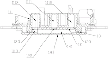
图4 是本实用新型中沿图3中剖面线C-C的剖视图。FIG. 4 is a cross-sectional view of the present invention along the section line C-C in FIG. 3 .
图5 是本实用新型中沿图3中剖面线E-E的剖视图。FIG. 5 is a cross-sectional view of the present utility model along section line E-E in FIG. 3 .
图6 是本实用新型中底壳的立体结构示意图。FIG. 6 is a schematic three-dimensional structure diagram of a bottom case of the present invention.
图7 是本实用新型中底壳的底视图。FIG. 7 is a bottom view of the bottom case of the present invention.
图8 是本实用新型水路盖板立体结构示意图。FIG. 8 is a schematic diagram of the three-dimensional structure of the waterway cover plate of the present invention.
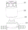
图9 是本实用新型泵体的结构示意图。FIG. 9 is a schematic structural diagram of the pump body of the present invention.
附图标号说明:10.外壳;101.透明盖板;102.上镜面;103.铝上盖;104.透明导光件;105.中饰板;106.下镜盖;107.LOGO支架;108.下盖;109.PCB板;11.底壳;111.过水槽;112.隔水板;113.出液口;114.进液口;115.第二凸台;116.第一凸台;117.限位凸块;118.进液管;119.出液管;12.水路盖板;121.放置槽;122.第一过水孔;123.第二过水孔;124.限位槽;1111.第一水腔;1112.第二水腔;1113.第三水腔;13.密封圈;14.吸热底板;141.散热片组;151.第一转接头;152.第二转接头;161.第一管套;162.第二管套;17.连接头密封圈;18.弧形支架;21.散热水排;22.泵体;221.驱动马达;222.叶轮管;223.叶轮;224.水泵三通管;225.防震套;231.下罩;232.上罩;241.第一编织管;242.第二编织管。Description of reference numerals: 10. Shell; 101. Transparent cover; 102. Upper mirror; 103. Aluminum upper cover; 104. Transparent light guide; 105. Middle trim; 106. Lower mirror cover; 107. LOGO bracket; 108. Lower cover; 109. PCB board; 11. Bottom case; 111. Water tank; 112. Water barrier; 113. Liquid outlet; 114. Liquid inlet; 115. Second boss; 117. Limiting bump; 118. Liquid inlet pipe; 119. Liquid outlet pipe; 12. Water channel cover plate; 121. Placement slot; Limit groove; 1111. First water cavity; 1112. Second water cavity; 1113. Third water cavity; 13. Sealing ring; .The second adapter; 161. The first pipe sleeve; 162. The second pipe sleeve; 17. The sealing ring of the connecting head; 18. The arc bracket; 223. Impeller; 224. Water pump tee pipe; 225. Anti-vibration sleeve; 231. Lower cover; 232. Upper cover;
具体实施方式Detailed ways
请参阅图1-9所示,本实用新型关于一种新型水冷散热器,包括与处理器散热面连接的吸热单元以及与吸热单元连通的散热单元,所述吸热单元包括由上至下依次连接的外壳10、底壳11、水路盖板12、吸热底板14;其中所述底壳11设置有与散热单元连通的进液管118以及出液管119,且所述散热单元与进液管118之间设置有泵体22;所述底壳11和水路盖板12之间围成与进液管118连接的第一水腔1111以及与出液管119流通的第二水腔1112,且所述第一水腔1111与第二水腔1112相互独立;所述吸热底板14与水路盖板12围成第三水腔1113,其中吸热底板14的表面固定设置有散热片组141,所述散热片组141设置在第三水腔1113内,所述水路盖板12表面设置有用于连通第一水腔1111与第三水腔1113的第一过水孔122、用于连通第二水腔1112与第三水腔1113的第二过水孔123,其中所述第一过水孔122沿垂直于散热片组141长度方向延伸,且水路盖板12的第二过水孔123设置在对应散热片组141两端的位置。Referring to FIGS. 1-9, the present invention relates to a novel water-cooled radiator, which includes a heat absorbing unit connected to the heat dissipation surface of the processor and a heat radiating unit communicated with the heat absorbing unit. The heat absorbing unit includes a The
当冷却液从进液管118进入第一水腔1111内,然后由第一过水孔122进去第三水腔1113内,同时由于所述散热片组141设置在第三水腔1113内,且第一过水孔122沿垂直于散热片组141长度方向延伸,故冷却液会进入散热片组141中多个散热片的间隙并沿着沿着散热片组141的长度方向流向两端,再从第二过水孔123流入第二水腔1112内,进而通过出液管119流向散热单元,并实现水路循环。故保证了冷却液能最大限度地与散热片组141中多个散热片接触,增加了冷却液对于散热片组141的接触面积,提高散热效果;同时由于水路流通过程为第一水腔1111到第三水腔1113再到第二水腔1112,整个水路为由先上至下流入,再由下至上流出,故冷却液液位肯定会高于散热片组141的高度并实现水路循环,故可以保证冷却液与散热片组141的完全接触,提高散热效果。When the cooling liquid enters the
在本申请中散热单元与进液管118之间设置有泵体22,相对于传统内置在吸热单元内,本申请的泵体22采用外置连接的方式,安装连接更加方便,性能更加优越,而且维修更加便捷。In this application, a
请参阅图1-9所示,本本实用新型的工作过程:Please refer to Fig. 1-9, the working process of the present invention:
冷却液通过泵体22的带动下从进液管118进入第一水腔1111中,然后由第一过水孔122进去第三水腔1113内,故冷却液会进入位于第三水腔1113的散热片组141中多个散热片的间隙并沿着散热片组141的长度方向流向散热片组141的两端,并将吸热底板14的热量并带走,同时位于第三水腔1113内的冷却液再从第二过水孔123流入第二水腔1112内,并流出出液管119,并将冷却液传输至散热单元作进一步散热,然后再循环进入进液管118中。Driven by the
请参阅图5所示,进一步,所述进液管118与第一水腔1111连接处设置进液口114;出液管119与第二水腔1112连接处设置出液口113。Referring to FIG. 5 , further, a
请参阅图6-7所示,进一步,所述底壳11底部设置有过水槽111,且所述过水槽111设置有“几”字型的隔水板112,其中过水槽111内壁与隔水板112的内侧面以及水路盖板12围成第一水腔1111,所述过水槽111内壁与隔水板112的外侧面以及水路盖板12围成第二水腔1112。在本具体实施例中,第一水腔1111位于过水槽111的中间位置,且呈“L”字形;所述第二水腔1112则呈“U”字形。Please refer to FIGS. 6-7 , further, the bottom of the
请参阅图6-7所示,进一步,所述过水槽111的内壁设置有限位凸块117,所述水路盖板12的外侧面设置与限位凸块117相对应的限位槽124,所述水路盖板12设置在过水槽111内,且所述限位凸块117插接在限位槽124内。在本具体实施例中,通过过水槽111的内壁设置限位凸块117,可以起到安装防错的作用,且限位凸块117与限位槽124的配合可以起到稳固作用,可以避免水路盖板12在工作过程中发生偏离的情况出现。Please refer to FIGS. 6-7 , further, the inner wall of the
请参阅图8所示,进一步,所述水路盖板12的底面设置放置槽121,所述吸热底板14设置在水路盖板12底部,且散热片组141设置在放置槽121内,为了提高散热片组141的散热效果,在本具体实施例中所述第一过水孔122开设在放置槽121的底部的中间位置,且与散热片组141的中心处对齐,故可以保证冷却液流向至散热片组141的两端的流量相同,则避免了冷却液在散热片组141的两端流量不相同导致的散热效果不佳的情况;同时所述第二过水孔123开设在放置槽121的底部两侧并与散热片组141的两端对齐,故可以保证水路的正常流通,而且在本具体实施例中,所述放置槽121的深度等于散热片组141的高度,既散热片组141与放置槽121底部贴紧,保证冷却液从第一过水孔122流出时,直接进入散热片组141的间隙;假设散热片组141不与放置槽121底部贴紧,即有冷却液从第一过水孔122流出时,有可能流向放置槽121与散热片组141之间的空间,最后只有小部分的冷却液与散热片组141接触,降低散热效果。Referring to FIG. 8 , further, a placement groove 121 is arranged on the bottom surface of the
请参阅图4-7所示,进一步,所述底壳11与吸热底板14的连接处设置有一圈密封槽,且所述密封槽内嵌设有一密封圈13,所述密封圈13横截面的面积大于密封槽横截面的面积。封圈横截面的面积大于密封槽横截面的面积,增加密封性,减少漏液机率。Please refer to FIGS. 4-7 , further, a sealing groove is provided at the connection between the
请参阅图4-7所示,进一步,所述吸热单元还包括弧形支架18,其中所述弧形支架18的两端设置有卡勾,其中所述底壳11的外侧面开设有一圈第一凸台116,且所述底壳11的外侧面沿周向均匀设置有多个位于第一凸台116下方的第二凸台115,且所述底壳11位于第一凸台116与第二凸台115之间的外侧面设置有对应卡勾的卡槽,所述弧形支架18卡设在第一凸台116与第二凸台115之间,并通过两端的卡勾与卡槽钩接并实现与底壳11的连接。在本具体实施例中,底壳11的四个方向设计有卡槽,当我们把弧形支架18卡设在第一凸台116与第二凸台115之间空间,同时使得弧形支架18两端的卡勾与卡槽钩接;即可以将弧形支架18与底壳11很好的固定结合在一起,免去了用螺丝固定繁琐的结构方式。而且第一凸台116以及第二凸台115对弧形支架18起到限位作用。Please refer to FIGS. 4-7 , further, the heat absorbing unit further includes an arc-shaped
请参阅图1-2所示,进一步,所述散热单元包括散热水排21、第一转接头151、第二转接头152、第一管套161、第二管套162、第一编织管241、第二编织管242,其中所述出液管119与第一转接头151连通,所述第一转接头151通过第一管套161连通第一编织管241的一端,所述第一编织管241另一端与散热水排21连通;所述进液管118与第二转接头152连通,所述第二转接头152通过第二管套162连通第二编织管242的一端,所述第二编织管242另一端与泵体22出水端连通,所述泵体22进水端与散热水排21连通;而且在本具体实施例中,第一转接头151与出液管119的连接处,以及第二转接头152与进液管118的连接处均设置有连接头密封圈17,可以增强出液管119以及进液管118的气密性,避免发生渗漏。1-2, further, the heat dissipation unit includes a heat
请参阅图2所示,进一步,所述散热单元还包括泵体罩,所述泵体罩包括上罩232、下罩231,而且上罩232、下罩231采用免螺丝上下卡钩固定方式。所述泵体22位于上罩232与下罩231围成的腔体内,且所述第二编织管242穿过该腔体与散热水排21连通。Please refer to FIG. 2 , further, the heat dissipation unit further includes a pump body cover, the pump body cover includes an
请参阅图9所示,在本具体实施例中,泵体22包括叶轮管222、驱动马达221、叶轮223、水泵三通管224,其中所述叶轮管222与水泵三通管224的一端连通,所述驱动马达221、叶轮223均设置在叶轮管222内,所述驱动马达221的输出轴与叶轮223连接,所述叶轮223沿其长度方向延伸至水泵三通管224内,且所述水泵三通管224的出水端与第二编织管242连通,所述水泵三通管224的进水端与散热水排21连通。而且在叶轮管222的表面套设有防震套225,套住水泵防止水泵运作与泵体罩振动产生噪音。Referring to FIG. 9 , in this specific embodiment, the
请参阅图1所示,进一步,所述外壳10包括透明盖板101、上镜面102、铝上盖103、透明导光件104、中饰板105、下镜盖106、LOGO支架107、下盖108、PCB板109,其中透明盖板101、铝上盖103、中饰板105、下盖108由上至下依次连接,且下盖108盖合在底壳11的表面;且所述上镜面102设置在透明盖板101与铝上盖103之间,所述透明导光件104设置在铝上盖103与中饰板105之间,下镜盖106、LOGO支架107设置在中饰板105与下盖108之间,且所述PCB板109设置在下盖108与底壳11之间。Please refer to FIG. 1 , further, the
以上实施方式仅仅是对本实用新型的优选实施方式进行描述,并非对本实用新型的范围进行限定,在不脱离本实用新型设计精神的前提下,本领域普通工程技术人员对本实用新型的技术方案作出的各种变形和改进,均应落入本实用新型的权利要求书确定的保护范围内。The above embodiments are only to describe the preferred embodiments of the present invention, and do not limit the scope of the present invention. On the premise of not departing from the design spirit of the present invention, ordinary engineers and technicians in the art make the technical solutions of the present invention. Various deformations and improvements should fall within the protection scope determined by the claims of the present utility model.
Claims (10)
Priority Applications (1)
| Application Number | Priority Date | Filing Date | Title |
|---|---|---|---|
| CN201921040740.2U CN209895295U (en) | 2019-07-04 | 2019-07-04 | A new type of water cooling radiator |
Applications Claiming Priority (1)
| Application Number | Priority Date | Filing Date | Title |
|---|---|---|---|
| CN201921040740.2U CN209895295U (en) | 2019-07-04 | 2019-07-04 | A new type of water cooling radiator |
Publications (1)
| Publication Number | Publication Date |
|---|---|
| CN209895295U true CN209895295U (en) | 2020-01-03 |
Family
ID=69022033
Family Applications (1)
| Application Number | Title | Priority Date | Filing Date |
|---|---|---|---|
| CN201921040740.2U Active CN209895295U (en) | 2019-07-04 | 2019-07-04 | A new type of water cooling radiator |
Country Status (1)
| Country | Link |
|---|---|
| CN (1) | CN209895295U (en) |
Cited By (2)
| Publication number | Priority date | Publication date | Assignee | Title |
|---|---|---|---|---|
| CN110377130A (en) * | 2019-07-04 | 2019-10-25 | 东莞市冰点智能科技有限公司 | A kind of water cooling radiator |
| CN113809027A (en) * | 2021-09-23 | 2021-12-17 | 东莞市冰点智能科技有限公司 | Water-cooling radiator with built-in semiconductor refrigerating system and fan |
-
2019
- 2019-07-04 CN CN201921040740.2U patent/CN209895295U/en active Active
Cited By (4)
| Publication number | Priority date | Publication date | Assignee | Title |
|---|---|---|---|---|
| CN110377130A (en) * | 2019-07-04 | 2019-10-25 | 东莞市冰点智能科技有限公司 | A kind of water cooling radiator |
| CN110377130B (en) * | 2019-07-04 | 2024-04-26 | 东莞市冰点智能科技有限公司 | A new type of water cooling radiator |
| CN113809027A (en) * | 2021-09-23 | 2021-12-17 | 东莞市冰点智能科技有限公司 | Water-cooling radiator with built-in semiconductor refrigerating system and fan |
| CN113809027B (en) * | 2021-09-23 | 2022-12-13 | 东莞市冰点智能科技有限公司 | Water-cooling radiator with built-in semiconductor refrigerating system and fan |
Similar Documents
| Publication | Publication Date | Title |
|---|---|---|
| CN110377130A (en) | A kind of water cooling radiator | |
| CN204721777U (en) | Electronic device and liquid cooling type heat dissipation structure thereof | |
| CN100371854C (en) | Liquid-cooled heat sink | |
| US11347284B2 (en) | Water cooling radiator with a detachable water pump and a built-in fan | |
| EP4123421A1 (en) | Water-cooled radiator | |
| CN214954895U (en) | A water cooling device | |
| CN211656711U (en) | An internal circulation water cooling device | |
| CN110718518B (en) | Cooling device for heat exchange of CPU radiator | |
| US20230180433A1 (en) | Water-cooling radiator | |
| CN111552363A (en) | Liquid cooling heat radiator | |
| CN209215849U (en) | Liquid cooling type radiator | |
| CN205281101U (en) | Integrated type liquid cooling system and projection equipment | |
| WO2020056954A1 (en) | Mechanism for cooling module by means of immersion, and frequency converter | |
| CN216982363U (en) | Liquid-cooled cooling module | |
| TWM591156U (en) | High efficiency liquid cooling heat dissipation system | |
| CN101266512A (en) | Integrated circulating water cooling heat sink suitable for computer interface card chip | |
| CN207020624U (en) | Water-cooled heat sink | |
| CN221175225U (en) | Radiating device of projection system and projection system | |
| CN215301281U (en) | Liquid cooling heat dissipation device and electronic equipment | |
| WO2024140928A1 (en) | Heat absorption assembly, heat sink, and lamp | |
| CN216429992U (en) | Servo cabinet heat removal device | |
| CN216388005U (en) | Water-cooling radiator | |
| CN206480615U (en) | Integrated liquid cooling device | |
| CN212229587U (en) | Liquid cooling heat radiator | |
| CN212256247U (en) | Novel water pump separation type water-cooling radiator with built-in fan |
Legal Events
| Date | Code | Title | Description |
|---|---|---|---|
| GR01 | Patent grant | ||
| GR01 | Patent grant |