EP3644126A1 - Manufacturing or regeneration method - Google Patents
Manufacturing or regeneration method Download PDFInfo
- Publication number
- EP3644126A1 EP3644126A1 EP18820813.6A EP18820813A EP3644126A1 EP 3644126 A1 EP3644126 A1 EP 3644126A1 EP 18820813 A EP18820813 A EP 18820813A EP 3644126 A1 EP3644126 A1 EP 3644126A1
- Authority
- EP
- European Patent Office
- Prior art keywords
- holder
- distance
- electrical contact
- information
- storage medium
- Prior art date
- Legal status (The legal status is an assumption and is not a legal conclusion. Google has not performed a legal analysis and makes no representation as to the accuracy of the status listed.)
- Granted
Links
Images





Classifications
-
- G—PHYSICS
- G03—PHOTOGRAPHY; CINEMATOGRAPHY; ANALOGOUS TECHNIQUES USING WAVES OTHER THAN OPTICAL WAVES; ELECTROGRAPHY; HOLOGRAPHY
- G03G—ELECTROGRAPHY; ELECTROPHOTOGRAPHY; MAGNETOGRAPHY
- G03G15/00—Apparatus for electrographic processes using a charge pattern
- G03G15/06—Apparatus for electrographic processes using a charge pattern for developing
- G03G15/08—Apparatus for electrographic processes using a charge pattern for developing using a solid developer, e.g. powder developer
- G03G15/0894—Reconditioning of the developer unit, i.e. reusing or recycling parts of the unit, e.g. resealing of the unit before refilling with toner
-
- G—PHYSICS
- G03—PHOTOGRAPHY; CINEMATOGRAPHY; ANALOGOUS TECHNIQUES USING WAVES OTHER THAN OPTICAL WAVES; ELECTROGRAPHY; HOLOGRAPHY
- G03G—ELECTROGRAPHY; ELECTROPHOTOGRAPHY; MAGNETOGRAPHY
- G03G21/00—Arrangements not provided for by groups G03G13/00 - G03G19/00, e.g. cleaning, elimination of residual charge
- G03G21/16—Mechanical means for facilitating the maintenance of the apparatus, e.g. modular arrangements
Definitions
- the present invention relates to a method of production or reproduction of an assembly including a storage medium and a holder.
- Electrophotographic image-forming apparatuses such as laser printers, LED printers and the like are well known in the art.
- the conventional image-forming apparatuses employ a developing cartridge.
- the developing cartridge has a developing roller for supplying developer.
- a conventional image-forming apparatus is described in Patent Literature 1, for example.
- the developing cartridge of the Patent Literature 1 is attached to a drum cartridge.
- the drum cartridge has a photosensitive drum.
- the drum cartridge is attached to the image-forming apparatus in a state where the developing cartridge is attached to the drum cartridge.
- Patent Literature 1 Japanese Patent Application Publication No. 2013-54058
- the storage medium is an IC chip, for example.
- the storage medium has electrical contact surfaces.
- the electrical contact surfaces of the storage medium are in contact with terminal parts in the image-forming apparatus.
- the storage medium is held by a holder.
- a holder capable of expanding and contracting may be used for pressing the electrical contact surfaces of the storage medium against the terminal parts of the image-forming apparatus.
- the holder may have a first outer surface in which the electrical contact surfaces are held, a second outer surface on the opposite side from the first outer surface, and an elastic member capable of expanding and contracting positioned between the first outer surface and the second outer surface.
- the position of the first outer surface is unstable in a case where this type of holder capable of expanding and contracting is used. Consequently, it is difficult to perform at least one of writing information to, deleting information from, and updating information in the IC chip when producing or reproducing the developing cartridge.
- the first invention of the present application provides a method of production or reproduction of an assembly, the assembly including: a storage medium having an electrical contact surface; and a holder configured to hold the electrical contact surface, the holder having: a first outer surface positioned at one side in a first direction crossing the electrical contact surface and configured to hold the electrical contact surface; a second outer surface positioned at another side in the first direction and apart from the first outer surface in the first direction; and an elastic member positioned between the first outer surface and the second outer surface and configured to expand and contract in the first direction, a distance in the first direction between the first outer surface and the second outer surface being changeable between a first distance and a second distance shorter than the first distance in accordance with expansion and contraction of the elastic member, the method including: a step of reducing the distance in the first direction between the first outer surface and the second outer surface to a prescribed distance shorter than the first distance by compressing the elastic member in the first direction; a step of maintaining the distance in the first direction between the first outer surface and the second outer
- the second invention of the present application provides the method according to the first invention, wherein the prescribed distance is the second distance.
- the third invention of the present application provides the method according to the first invention, wherein the prescribed distance is shorter than the first distance and longer than the second distance.
- the fourth invention of the present application provides the method according to any one of the first to third invention, further including a step of fixing the electrical contact surface to the first outer surface, wherein the distance in the first direction between the first outer surface and the second outer surface is reduced to the prescribed distance shorter than the first distance by compressing the elastic member after fixing the electrical contact surface to the first outer surface.
- the fifth invention of the present application provides the method according to any one of the first to fourth invention, wherein the holder is attachable to a casing configured to accommodate a developing agent, and wherein at least one of writing information to, deleting information from, and updating information in the storage medium is performed in a state where the holder is attached to the casing.
- the sixth invention of the present application provides the method according to the fifth invention, further including a step of attaching the holder to the casing before performing at least one of writing information to, deleting information from, and updating information in the storage medium.
- the seventh invention of the present application provides the method according to the fifth invention or the sixth invention, wherein a developing roller is positioned at an end portion of the casing in a second direction, wherein the holder is movable in the second direction relative to the casing, and wherein at least one of writing information to, deleting information from, and updating information in the storage medium is performed by bringing the probe into contact with the electrical contact surface in a state where a position of the holder is fixed in the second direction relative to the casing.
- the eighth invention of the present application provides the method according to any one of the first to fourth invention, wherein the holder is attachable to a casing configured to accommodate a developing agent, and wherein at least one of writing information to, deleting information from, and updating information in the storage medium is performed in a state where the holder is not attached to the casing.
- the ninth invention of the present application provides the method according to the eighth invention, further including a step of attaching the holder to the casing after performing at least one of writing information to, deleting information from, and updating information in the storage medium in a state where the holder is not attached to the casing.
- the tenth invention of the present application provides the method according to any one of the first to ninth invention, wherein a jig presses at least one of the first outer surface and the second outer surface in the first direction to contract the elastic member in the first direction.
- the eleventh invention of the present application provides the method according to the tenth invention, wherein the jig presses a portion of the first outer surface encompassing the electrical contact surface.
- the twelfth invention of the present application provides the method according to any one of the first to eleventh invention, wherein information is written to the storage medium by bringing the probe into contact with the electrical contact surface.
- the thirteenth invention of the present application provides the method according to any one of the first to eleventh invention, wherein information is updated in the storage medium by bringing the probe into contact with the electrical contact surface.
- the fourteenth invention of the present application provides the method according to any one of the first to eleventh invention, wherein information is deleted from the storage medium by bringing the probe into contact with the electrical contact surface.
- the fifteenth invention of the present application provides the method according to any one of the first to fourteenth invention, wherein the first outer surface is configured to hold the storage medium including the electrical contact surface.
- the sixteenth invention of the present application provides the method according to any one of the first to fifteenth invention, wherein the storage medium is an IC chip.
- the seventeenth invention of the present application provides the method according to any one of the first to sixteenth invention, wherein the storage medium is used in a developing cartridge.
- At least one of writing information to, deleting information from, and updating information in the storage medium can be performed in a state where the position of the electrical contact surface in the first direction is in a stable state.
- At least one of writing information to, deleting information from, and updating information in the storage medium can be performed in a state where the position of the electrical contact surface in the first direction is in a more stable state.
- the position of the electrical contact surface in the first direction can be stabilized in a case where large dimensional errors exist in a contact portion for setting the distance between the first outer surface and the second outer surface to the second distance.
- an inconsistency is unlikely to arise between the specifications of the casing and the information stored in the storage medium after at least one of writing information to, deleting information from, and updating information in the storage medium was performed.
- the equipment used for performing at least one of writing information to, deleting information from, and updating information in the storage medium can be made more compact.
- first direction a direction crossing electrical contact surfaces of an IC chip
- second direction a direction between one side of a casing of the developing cartridge in which a developing roller is positioned and the opposite side of the casing
- third direction a direction in which the casing of the developing cartridge extends.
- the first direction and the second direction cross each other (and preferably are orthogonal to each other).
- the second direction and the third direction cross each other (and preferably are orthogonal to each other).
- third direction and the first direction cross each other (and preferably are orthogonal to each other).
- Fig. 1 is a conceptual diagram illustrating an image-forming apparatus 100.
- This image-forming apparatus 100 is an electrophotographic printer.
- a laser printer and an LED printer are examples of the image-forming apparatus 100.
- the image-forming apparatus 100 includes four process cartridges 10 and a process-cartridge holder 90.
- Each process cartridge 10 includes a developing cartridge 1 and a drum cartridge 2.
- the developing cartridge 1 is attachable to the drum cartridge 2.
- the four developing cartridges 1 respectively accommodate therein developing agents of different colors (for example, cyan, magenta, yellow, and black). However, the number of the developing cartridge(s) 1 may be any one of one through three, and can be five or more.
- the process-cartridge holder 90 is a frame to which the process cartridges 10 are attachable.
- the process-cartridge holder 90 has four slots 91. Each process cartridge 10 can be attached to each slot 91.
- the image-forming apparatus 100 is configured to form an image on a recording surface of a printing sheet by the developing agents (such as toner) supplied from the four developing cartridges 1 of the four process cartridges 10.
- Each of the four developing cartridges 1 includes an IC chip 51.
- the IC chip 51 is a storage medium from which information is readable and to which information is writable.
- the image-forming apparatus 100 also includes a controller 80.
- the IC chip 51 of each developing cartridge 1 is electrically connected to the controller 80 as a result of attachment of the process cartridge 10 to the slot 91 of the process-cartridge holder 91.
- the controller 80 is constituted by, for example, a circuit board.
- the controller 80 includes a processor such as a CPU and the like and various memories.
- the controller 80 controls various processes executed in the image-forming apparatus 100 by operations of the processor in accordance with programs.
- Fig. 2 is a perspective view of the process cartridge 10.
- the process cartridge 10 includes the developing cartridge 1 and the drum cartridge 2.
- the developing cartridge 1 is attachable to and detachable from the drum cartridge 2.
- the user of the image-forming apparatus 100 can replace any one of the developing cartridge 1 and the drum cartridge 2 with a new cartridge. Accordingly, each product life of the developing cartridge 1 and the drum cartridge 2 can be effectively consumed.
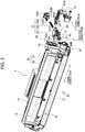
- Fig. 3 is a perspective view of the developing cartridge 1.
- Fig. 3 illustrates a partially exploded view of the developing cartridge 1.
- the developing cartridge 1 includes: a casing 11; an agitator 20; a developing roller 30; a gear portion 40; and an IC chip assembly 50.
- the casing 11 is a casing configured to accommodate a developing agent.
- the casing 11 extends in the third direction.
- An accommodation chamber 13 is provided in an interior of the casing 11.
- the developing agent is accommodated in the accommodation chamber 13.
- the casing 11 has an opening 14.
- the opening 14 is positioned at one end portion of the casing 11 in the second direction.
- the accommodation chamber 13 communicates with an outside of the casing 11 through the opening 14.
- the agitator 20 includes an agitator shaft 21 and an agitation blade 22.
- the agitator shaft 21 extends in the third direction.
- the agitation blade 22 extends radially outward from the agitator shaft 21. At least part of the agitator shaft 21 and the agitation blade 22 are positioned inside the accommodation chamber 13.
- the gear potion 40 includes an agitator gear connected to one end portion of the agitator shaft 21 in the third direction.
- the agitator shaft 21 and the agitation blade 22 rotate along with rotation of the agitator gear. In accordance with rotation of the agitation blade 22, the developing agent in the accommodation chamber 13 is agitated.
- the developing roller 30 is a roller rotatable about a rotation axis (first rotation axis) extending in the third direction.
- the developing roller 30 is positioned at the opening 14 of the casing 11. That is, the developing roller 30 is positioned at the one end portion of the casing 11 in the second direction.
- the developing roller 30 of the present embodiment includes a developing-roller body 31 and a developing-roller shaft 32.
- the developing-roller body 31 is a hollow cylindrical member extending in the third direction.
- the developing-roller shaft 32 is made from material such as rubber having elasticity, for example.
- the developing-roller shaft 32 is a solid cylindrical member extending through the developing-roller body 31 in the third direction.
- the developing-roller shaft 32 is made from material such as metal or electrically conductive resin.
- the developing-roller body 31 is fixed to the developing-roller shaft 32 so as not to rotate relative to the developing-roller shaft 32.
- the gear portion 40 includes a developing-roller gear to which one end portion of the developing-roller shaft 32 in the third direction is fixed so as not to rotate relative to the developing roller gear. That is, the developing-roller shaft 32 rotates by the rotation of the developing-roller gear, and the developing-roller body 31 also rotates along with the developing-roller shaft 32.
- developing-roller shaft 32 does not necessarily penetrate the developing-roller body 31 in the third direction.
- a pair of developing-roller shafts 32 may extend in the third direction from both ends of the developing-roller body 31 in the third direction, respectively.
- the developing cartridge 1 further includes an unillustrated supply roller.
- the supply roller is positioned between the developing roller 30 and the accommodation chamber 13.
- the supply roller is rotatable about a rotation axis extending in the third direction.
- the developing agent accommodated in the accommodation chamber 13 of the casing 11 is supplied to an outer peripheral surface of the developing roller 30 through the supply roller upon receipt of driving force in the developing cartridge 1.
- the developing agent is tribo-electrically charged between the supply roller and the developing roller 30.
- a bias voltage is applied to the developing-roller shaft 32 of the developing roller 30. Therefore, the developing agent is attracted to the outer peripheral surface of the developing-roller body 31 by an electrostatic force between the developing-roller shaft 32 and the developing agent.
- the developing cartridge 1 further includes an unillustrated layer-thickness regulation blade.
- the layer-thickness regulation blade is configured to regulate the developing agent supplied over the outer peripheral surface of the developing-roller body 31 into a uniform thickness. Then, the developing agent on the outer peripheral surface of the developing-roller body 31 is supplied to a photosensitive drum 72 described later. In this instance, the developing agent moves from the developing-roller body 31 to the photosensitive drum 72 according to an electrostatic latent image formed on the outer peripheral surface of the photosensitive drum 72. Hence, the electrostatic latent image is developed into a visible image on the outer peripheral surface of the photosensitive drum 72.
- the gear portion 40 is positioned at a first end face 12, which is one end face of the casing 11 in the third direction.
- the gear portion 40 includes: a plurality of gears including the above-described agitator gear and developing-roller gear; a coupling 41; and a gear cover 45.
- the gear cover 45 is fixed to the first end face 12 of the casing 11 by, for example, screws. At least part of the plurality of gears is positioned between the first end face 12 and the gear cover 45.
- the coupling 41 is exposed to the outside of the gear cover 45.
- the developing cartridge 1 further includes a holder cover 47.
- the holder cover 47 is fixed to the gear cover 45.
- the holder cover 47 is positioned opposite to the casing 11 with respect to the gear cover 45 in the third direction.
- the plurality of gears of the gear portion 40 may be gears configured to transmit a rotation force by meshing engagements of teeth or gears configured to transmit a rotation force by friction between the gears.
- the IC chip assembly 50 is attached to the casing 11.
- Fig. 4 is an exploded perspective view of the IC chip assembly 50.
- the IC chip assembly 50 includes: the IC chip 51 as a storage medium; and a holder 52 configured to hold the IC chip 51.
- the IC chip 51 has four electrical contact surfaces 511. Each electrical contact surface 511 is made from electrically conductive metal. Further, the IC chip 51 is configured to store various information on the developing cartridge 1. However, the number of the electrical contact surface(s) 511 of the IC chip 51 may be one through three, or can be five or more.
- the holder 52 has a first outer surface 52A and a second outer surface 52B.
- the first outer surface 52A is positioned at one end of the holder 52 in the first direction.
- the second outer surface 52B is positioned at another end of the holder 52 in the first direction.
- the first outer surface 52A is movable in the first direction relative to the second outer surface 52B.
- the holder 52 of the present embodiment includes: a first holder member 521; a second holder member 522; and a coil spring 523 interposed therebetween.
- the first holder member 521 is made from resin, for example.
- the second holder member 522 is made from resin, for example.
- the first holder member 521 has the first outer surface 52A.
- the IC chip 51 is fixed to a holding surface 520 included in the first outer surface 52A. Hence, the electrical contact surfaces 511 of the IC chip 51 are held by the first outer surface 52A.
- the second holder member 522 has the second outer surface 52B. Upon assembly of the holder 52, the first outer surface 52A and the second outer surface 52B are away from each other in the first direction.
- the coil spring 523 is an elastic member configured to expand and contract in the first direction.
- the coil spring 523 is positioned between the first outer surface 52A and the second outer surface 52B in the first direction.
- One end of the coil spring 523 in the first direction may be directly connected to the first holder member 521 or may be indirectly connected to the first holder member 521 via another member.
- another end of the coil spring 523 in the first direction may be directly connected to the second holder member 522 or may be indirectly connected to the second holder member 522 via another member.
- the distance in the first direction between the first outer surface 52A and the second outer surface 52B changes as the coil spring 523 expands and contracts.
- the length of the coil spring 523 in the first direction changes at least between a first length and a second length shorter than the first length.
- the distance in the first direction between the first outer surface 52A and the second outer surface 52B is a first distance.
- the distance in the first direction between the first outer surface 52A and the second outer surface 52B is a second distance shorter than the first distance.
- the second length is at least shorter than the natural length of the coil spring 523.
- the second holder member 522 includes a cylindrically shaped spring holder 522A.
- the spring holder 522A protrudes toward the first holder member 521 in the first direction from the surface of the second holder member 522 facing the first holder member 521.
- a portion of the coil spring 523 is inserted inside the spring holder 522A.
- the second holder member 522 has a columnar-shaped protruding part (not illustrated) inside the spring holder 522A. Therefore, the coil spring 523 is supported by the outer circumferential surface of the protruding part and the inner circumferential surface of the spring holder 522A.
- the second holder member 522 also has a first pawl portion 522B and a second pawl portion 522C.
- the first pawl portion 522B extends toward the first holder member 521 in the first direction from the surface of the second holder member 522 facing the first holder member 521.
- the distal end of the first pawl portion 522B protrudes in a direction crossing the first direction.
- the second pawl portion 522C also extends toward the first holder member 521 in the first direction from the surface of the second holder member 522 facing the first holder member 521.
- the distal end of the second pawl portion 522C protrudes in a direction crossing the first direction.
- the first holder member 521 has a first opening 521A.
- the distal end of the first pawl portion 522B is inserted into the first opening 521A.
- the first holder member 521 has a second opening (not illustrated).
- the distal end of the second pawl portion 522C is inserted into the second opening.
- the first pawl portion 522B is made in contact with the first holder member 521 at the edge of the first opening 521A on the second outer surface 52B side. Further, when the coil spring 523 is at the first length, the second pawl portion 522C is made in contact with the first holder member 521 at the edge of the second opening on the second outer surface 52B side. In this way, the coil spring 523B is prevented from being made longer in the first direction than the first length. In addition, disengagement of the first holder member 521 from the second holder member 522 is prevented.
- the first pawl portion 522B is made in contact with the first holder member 521 at the edge of the first opening 521A on the first outer surface 52A side.
- the second pawl portion 522C is made in contact with the first holder member 521 at the edge of the second opening on the first outer surface 52A side. In this way, the coil spring 523 is prevented from being made shorter in the first direction than the second length.
- the IC chip 51 is fixed to the holding surface 520 included in the first outer surface 52A of the first holder member 521. Hence, movement of the first holder member 521 in the second direction relative to the second holder member 522 causes the electrical contact surfaces 511 of the IC chip 51 to move in the first direction.
- the first outer surface 52A in the present embodiment has a recessed part that is recessed toward the second holder member 522 in the first direction.
- the holding surface 520 is positioned in this recessed part.
- the first holder member 521 includes: a first boss 53A; a second boss 53B; and a third boss 53C.
- Each of the first boss 53A and the second boss 53B extends in the first direction toward the gear cover 45 from a surface of the first holder member 521 facing the gear cover 45.
- the gear cover 45 has a first through-hole 45A and a second through-hole 45B.
- Each of the first through-hole 45A and the second through-hole 45B penetrates the gear cover 45 in the first direction.
- the first boss 53A is inserted into the first through-hole 45A.
- the second boss 53B is inserted into the second through-hole 45B.
- the third boss 53C extends in the first direction toward the holder cover 47 from another surface of the first holder member 521 facing the holder cover 47.
- the holder cover 47 has a third through-hole 47A.
- the third through-hole 47A penetrates the holder cover 47 in the first direction.
- the third boss 63C is inserted into the third through-hole 47A.
- the first through-hole 45A has a dimension (inner dimension) in the first direction that is greater than a dimension (outer dimension) in the first direction of the first boss 53A.
- the second through-hole 45B has a dimension (inner dimension) in the first direction that is greater than a dimension (outer dimension) in the first direction of the second boss 53B.
- the third through-hole 47A has a dimension (inner dimension) in the first direction that is greater than a dimension (outer dimension) in the first direction of the third boss 53C.
- the first through-hole 45A has a dimension (inner dimension) in the second direction that is greater than a dimension (outer dimension) in the second direction of the first boss 53A.
- the second through-hole 45B has a dimension (inner dimension) in the second direction that is greater than a dimension (outer dimension) in the second direction of the second boss 53B.
- the third through-hole 47A has a dimension (inner dimension) in the second direction that is greater than a dimension (outer dimension) in the second direction of the third boss 53C.
- the gear cover 45 may have, instead of the first through-hole 45A, a recessed portion into which the first boss 53A can be inserted. Further, the gear cover 45 may have, instead of the second through-hole 45B, a recessed portion into which the second boss 53B can be inserted.
- the holder cover 47 may have, instead of the third through-hole 47A, a recessed portion into which the third boss 53C can be inserted. Further, the gear cover 45 may have a boss, and the first holder member 521 may have a through-hole or a recessed portion into which the boss can be inserted.
- the holder cover 47 may have a boss, and the first holder member 521 may have a through-hole or a recessed portion into which the boss can be inserted.
- one of the casing configured of the casing 11, the gear cover 45, and the holder cover 47, and the holder 52 may have a boss, and another of the casing and the holder 52 may have a through-hole or a recessed portion into which the boss can be inserted.
- Fig. 5 is a perspective view of the drum cartridge 2.
- the drum cartridge 2 includes a single developing-cartridge holding portion 71 for holding a single developing cartridge 1.
- the photosensitive drum 72 is positioned at the developing-cartridge holding portion 71.
- the photosensitive drum 72 is rotatable about a rotation axis (second rotation axis) extending in the third direction.
- the developing roller 30 of the developing cartridge 1 comes in contact with the photosensitive drum 72 as a result of attachment of the developing cartridge 1 to the drum cartridge 2.
- the drum cartridge 2 to which the developing cartridge 1 is attached is attached to the process-cartridge holder 90 (see Fig. 1 ) provided in the image-forming apparatus 100.
- a holding plate 731 is provided at one end portion of the developing-cartridge holding portion 71 in the third direction.
- the holding plate 731 is positioned such that the second outer surface 52B of the holder 52 faces the holding plate 731 in the first direction in a state where the developing cartridge 1 is attached to the drum cartridge 2.
- the holding plate 731 has a surface extending in the second direction and the third direction.
- the holding plate 731 also has a protruding portion 73.
- the protruding portion 73 protrudes toward the holder 52 in the third direction from the holding plate 731. Further, protruding portion 73 converges toward the holder 52 in the shape of a quadrangular pyramid.
- the second holder member 522 of the IC chip assembly 50 has a cavity 522D in the second outer surface 52B (see Figs. 7 through 9 ).
- the cavity 522D is recessed from the second outer surface 52B toward the first holder member 521.
- the cavity 522D also converges toward the first holder member 521 in the shape of a quadrangular pyramid.
- the protruding portion 73 of the drum cartridge 2 is fitted with the cavity 522D of the second holder member 522. Then, the holding plate 731 is made in contact with the second outer surface 52B of the second holder member 522. That is, the holding plate 731 and the protruding portion 73 function as a holder supporting portion for holding the holder 52 of the IC chip assembly 50.
- FIG. 6 is a flowchart illustrating the production procedure for the developing cartridge 1.
- the production procedure in Fig. 6 includes a production procedure for the IC chip assembly 50. Each of the following steps may be performed manually by the manufacturer or may be performed using automated equipment.
- the manufacturer When producing the developing cartridge 1, first the manufacturer assembles the casing 11, the agitator 20, the developing roller 30, and the gear portion 40 (step S1). The manufacturer also assembles the holder 52 of the IC chip assembly 50 (step S2). Next, the manufacturer fixes the IC chip 51 having the electrical contact surfaces 511 to the first outer surface 52A of the holder 52 (step S3). However, the manufacturer may perform step S1 after steps S2 and S3 or may perform step S1 at the same time as steps S2 and S3.
- the manufacturer attaches the holder 52 to the casing 11 (step S4).
- the manufacturer attaches the holder 52 to the gear cover 45, which is fixed to the casing 11.
- the first boss 53A of the holder 52 is inserted into the first through-hole 45A of the gear cover 45.
- the second boss 53B of the holder 52 is inserted into the second through-hole 45B of the gear cover 45.
- the holder cover 47 is attached to the gear cover 45, with the third boss 53C of the holder 52 being inserted through the third through-hole 47A of the holder cover 47.
- the manufacturer compresses the holder 52 in the first direction (step S5). That is, the manufacturer applies an external force to each of the first outer surface 52A of the first holder member 521 and the second outer surface 52B of the second holder member 522 in directions for bringing the first outer surface 52A and the second outer surface 52B toward each other.
- the length of the coil spring 523 in the first direction is compressed from the first length to a prescribed length shorter than the first length.
- the distance in the first direction between the first outer surface 52A and the second outer surface 52B changes from the first distance to a prescribed distance shorter than the first distance.
- Fig. 7 is a cross-sectional view of the holder 52 prior to being compressed in the first direction.
- Fig. 8 is a cross-sectional view of the holder 52 when compressed in the first direction.
- the jig presses at least one of the first outer surface 52A and the second outer surface 52B of the holder 52 in the first direction.
- the length of the coil spring 523 in the first direction is maintained at the prescribed length. Accordingly, the distance in the first direction between the first outer surface 52A and the second outer surface 52B is maintained at the prescribed distance.
- the first outer surface 52A in the present embodiment has a step surface 52C.
- the step surface 52C is positioned between the holding surface 520 that holds the electrical contact surfaces 511 and the casing 11 in the third direction.
- the step surface 52C extends in the second direction and the third direction. The jig presses this step surface 52C, for example.
- the "prescribed distance” described above may be the second distance, for example.
- the manufacturer may reduce the distance in the first direction between the first outer surface 52A and the second outer surface 52B to the second distance, for example.
- the length of the coil spring 523 in the first direction is the second length.
- the distal end of the first pawl portion 522B is made in contact with the first holder member 521 at the edge of the first opening 521A on the first outer surface 52A side.
- the distal end of the second pawl portion 522C is made in contact with the first holder member 521 at the edge of the second opening on the first outer surface 52A side.
- the positions of the electrical contact surfaces 511 in the first direction are stable.
- the distal end of the spring holder 522A may contact the first holder member 521 when the distance in the first direction between the first outer surface 52A and the second outer surface 52B is the second distance.
- the "prescribed distance" described above may be a distance shorter than the first distance and longer than the second distance.
- the manufacturer may reduce the distance in the first direction between the first outer surface 52A and the second outer surface 52B to a distance shorter than the first distance and longer than the second distance. Setting the distance in the first direction between the first outer surface 52A and the second outer surface 52B to a distance greater than the second distance can stabilize the positions of the electrical contact surfaces 511 in the first direction in a case where large dimensional errors exist in the first opening 521A, the first pawl portion 522B, the second opening, or the second pawl portion 522C.
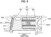
- Fig. 9 is a cross-sectional view of the holder 52 when information is being written to the IC chip 51.
- a probe 60 is in contact with the electrical contact surfaces 511 when writing information to the IC chip 51.
- the probe 60 may be oriented perpendicularly to the electrical contact surfaces 511, as illustrated in Fig. 9 , or may be oriented obliquely to the electrical contact surfaces 511.
- the distance in the first direction between the first outer surface 52A and the second outer surface 52B is maintained at the prescribed distance. Therefore, information is written to the IC chip 51 in a state where the positions of the electrical contact surfaces 511 in the first direction are in a stable state.
- a particular feature of the embodiment is that information is written to the IC chip 51 in a state where the holder 52 is attached to the casing 11. Therefore, an inconsistency is unlikely to arise between the specifications of developer accommodated in the casing 11 and the information stored in the IC chip 51 after writing has been performed.
- step S7 the probe 60 contacts the electrical contact surfaces 511 to write information to the IC chip 51 in a state where not only the position of the first outer surface 52A is fixed in the first direction relative to the casing 11 but also the position of the holder 52 is fixed in the second direction relative to the casing 11. Consequently, information can be more reliably written to the IC chip 51.
- the manufacturer examines the information that has been written to the IC chip 51 (step S8). Specifically, the electrodes of an inspection tool are placed in contact with the electrical contact surfaces 511 on the IC chip 51. The inspection tool then reads the information stored in the IC chip 51 via the electrical contact surfaces 511, enabling the manufacturer to determine whether the information stored in the memory is correct.
- Fig. 10 is a flowchart illustrating a variation of the production procedure for the developing cartridge 1.
- the order of steps S4 through S7 differs from that in the embodiment described above.
- the manufacturer compresses the holder 52 in the first direction (step S5) and mounts the holder 52 in the jig (step S6) after completing step S3.
- the manufacturer writes information to the IC chip 51 (step S7).
- the manufacturer writes information to the IC chip 51 in a state where the holder 52 is not attached to the casing 11.
- the manufacturer attaches the holder 52 to the casing 11 (step S4).
- the above-described embodiment describes a procedure used when the manufacturer is producing a new developing cartridge 1.
- the operator may reproduce the IC chip assembly 50 by performing the process in steps S2-S8 described above.
- deleting information from the IC chip 51 or updating information in the IC chip 51 may be performed instead of writing information to the IC chip 51 in step S7.
- at least one of the operations for writing information to, deleting information from, and updating information in the IC chip 51 may be performed by bringing the probe 60 into contact with the electrical contact surfaces 511.
- the above-described embodiment describes the production or reproduction of the IC chip assembly 50 used in the developing cartridge 1.
- the IC chip assembly 50 may be a component used in another product.
- the IC chip assembly 50 may be a component used in the drum cartridge 2.
- the coil spring 523 is employed as an elastic member.
- other kinds of springs such as a leaf spring, a torsion spring and the like are also available instead of the coil spring 523.
- the IC chip having the electrical contact surfaces is fixed to the outer surface of the holder.
- only the electrical contact surfaces configured to contact the electrical connector may be fixed to the outer surface of the holder, while a remaining portion of the IC chip other than the electrical contact surfaces may be positioned at a different portion of the developing cartridge.
- each part and component constituting the image-forming apparatus may have a shape different from that of the above-described embodiment illustrated in the accompanying drawings. Further, parts and components described in the embodiment and variations described above may be appropriately combined as long as such combinations can avoid conflicting problem.
Landscapes
- Physics & Mathematics (AREA)
- General Physics & Mathematics (AREA)
- Life Sciences & Earth Sciences (AREA)
- Sustainable Development (AREA)
- Electrophotography Configuration And Component (AREA)
- Ink Jet (AREA)
- Accessory Devices And Overall Control Thereof (AREA)
- Dry Development In Electrophotography (AREA)
Abstract
Description
- The present invention relates to a method of production or reproduction of an assembly including a storage medium and a holder.
- Electrophotographic image-forming apparatuses such as laser printers, LED printers and the like are well known in the art. The conventional image-forming apparatuses employ a developing cartridge. The developing cartridge has a developing roller for supplying developer. A conventional image-forming apparatus is described in
Patent Literature 1, for example. - The developing cartridge of the
Patent Literature 1 is attached to a drum cartridge. The drum cartridge has a photosensitive drum. The drum cartridge is attached to the image-forming apparatus in a state where the developing cartridge is attached to the drum cartridge. - [PTL1]
Patent Literature 1: Japanese Patent Application Publication No.2013-54058 - Conventional developing cartridges including a storage medium are also known in the art. The storage medium is an IC chip, for example. The storage medium has electrical contact surfaces. The electrical contact surfaces of the storage medium are in contact with terminal parts in the image-forming apparatus. The storage medium is held by a holder. A holder capable of expanding and contracting may be used for pressing the electrical contact surfaces of the storage medium against the terminal parts of the image-forming apparatus. Specifically, the holder may have a first outer surface in which the electrical contact surfaces are held, a second outer surface on the opposite side from the first outer surface, and an elastic member capable of expanding and contracting positioned between the first outer surface and the second outer surface.
- However, the position of the first outer surface is unstable in a case where this type of holder capable of expanding and contracting is used. Consequently, it is difficult to perform at least one of writing information to, deleting information from, and updating information in the IC chip when producing or reproducing the developing cartridge.
- It is an object of the present invention to perform at least one of writing information to, deleting information from, and updating information in the storage medium in a state where the position of the electrical contact surfaces in a first direction crossing the electrical contact surfaces is stabilized when the holder holding the electrical contact surfaces is capable of expanding and contracting in the first direction.
- In order to attain the above object, the first invention of the present application provides a method of production or reproduction of an assembly, the assembly including: a storage medium having an electrical contact surface; and a holder configured to hold the electrical contact surface, the holder having: a first outer surface positioned at one side in a first direction crossing the electrical contact surface and configured to hold the electrical contact surface; a second outer surface positioned at another side in the first direction and apart from the first outer surface in the first direction; and an elastic member positioned between the first outer surface and the second outer surface and configured to expand and contract in the first direction, a distance in the first direction between the first outer surface and the second outer surface being changeable between a first distance and a second distance shorter than the first distance in accordance with expansion and contraction of the elastic member, the method including: a step of reducing the distance in the first direction between the first outer surface and the second outer surface to a prescribed distance shorter than the first distance by compressing the elastic member in the first direction; a step of maintaining the distance in the first direction between the first outer surface and the second outer surface at the prescribed distance; and a step of performing at least one of writing information to, deleting information from, and updating information in the storage medium by bringing a probe into contact with the electrical contact surface in a state where the distance in the first direction between the first outer surface and the second outer surface is maintained at the prescribed distance.
- The second invention of the present application provides the method according to the first invention, wherein the prescribed distance is the second distance.
- The third invention of the present application provides the method according to the first invention, wherein the prescribed distance is shorter than the first distance and longer than the second distance.
- The fourth invention of the present application provides the method according to any one of the first to third invention, further including a step of fixing the electrical contact surface to the first outer surface, wherein the distance in the first direction between the first outer surface and the second outer surface is reduced to the prescribed distance shorter than the first distance by compressing the elastic member after fixing the electrical contact surface to the first outer surface.
- The fifth invention of the present application provides the method according to any one of the first to fourth invention, wherein the holder is attachable to a casing configured to accommodate a developing agent, and wherein at least one of writing information to, deleting information from, and updating information in the storage medium is performed in a state where the holder is attached to the casing.
- The sixth invention of the present application provides the method according to the fifth invention, further including a step of attaching the holder to the casing before performing at least one of writing information to, deleting information from, and updating information in the storage medium.
- The seventh invention of the present application provides the method according to the fifth invention or the sixth invention, wherein a developing roller is positioned at an end portion of the casing in a second direction, wherein the holder is movable in the second direction relative to the casing, and wherein at least one of writing information to, deleting information from, and updating information in the storage medium is performed by bringing the probe into contact with the electrical contact surface in a state where a position of the holder is fixed in the second direction relative to the casing.
- The eighth invention of the present application provides the method according to any one of the first to fourth invention, wherein the holder is attachable to a casing configured to accommodate a developing agent, and wherein at least one of writing information to, deleting information from, and updating information in the storage medium is performed in a state where the holder is not attached to the casing.
- The ninth invention of the present application provides the method according to the eighth invention, further including a step of attaching the holder to the casing after performing at least one of writing information to, deleting information from, and updating information in the storage medium in a state where the holder is not attached to the casing.
- The tenth invention of the present application provides the method according to any one of the first to ninth invention, wherein a jig presses at least one of the first outer surface and the second outer surface in the first direction to contract the elastic member in the first direction.
- The eleventh invention of the present application provides the method according to the tenth invention, wherein the jig presses a portion of the first outer surface encompassing the electrical contact surface.
- The twelfth invention of the present application provides the method according to any one of the first to eleventh invention, wherein information is written to the storage medium by bringing the probe into contact with the electrical contact surface.
- The thirteenth invention of the present application provides the method according to any one of the first to eleventh invention, wherein information is updated in the storage medium by bringing the probe into contact with the electrical contact surface.
- The fourteenth invention of the present application provides the method according to any one of the first to eleventh invention, wherein information is deleted from the storage medium by bringing the probe into contact with the electrical contact surface.
- The fifteenth invention of the present application provides the method according to any one of the first to fourteenth invention, wherein the first outer surface is configured to hold the storage medium including the electrical contact surface.
- The sixteenth invention of the present application provides the method according to any one of the first to fifteenth invention, wherein the storage medium is an IC chip.
- The seventeenth invention of the present application provides the method according to any one of the first to sixteenth invention, wherein the storage medium is used in a developing cartridge.
- According to the first to seventeenth invention of the present application, at least one of writing information to, deleting information from, and updating information in the storage medium can be performed in a state where the position of the electrical contact surface in the first direction is in a stable state.
- Further, according to the second invention of the present application, at least one of writing information to, deleting information from, and updating information in the storage medium can be performed in a state where the position of the electrical contact surface in the first direction is in a more stable state.
- Further, according to the third invention of the present application, the position of the electrical contact surface in the first direction can be stabilized in a case where large dimensional errors exist in a contact portion for setting the distance between the first outer surface and the second outer surface to the second distance.
- Further, according to the fifth invention of the present application, an inconsistency is unlikely to arise between the specifications of the casing and the information stored in the storage medium after at least one of writing information to, deleting information from, and updating information in the storage medium was performed.
- Further, according to the eighth invention of the present application, the equipment used for performing at least one of writing information to, deleting information from, and updating information in the storage medium can be made more compact.
- Further, according to the eleventh invention of the present application, contact between the jig and the electrical contact surface can be avoided.
-
- [
Fig. 1 ]
Fig. 1 is a conceptual diagram illustrating an image-forming apparatus. - [
Fig. 2 ]
Fig. 2 is a perspective view of a process cartridge. - [
Fig. 3 ]
Fig. 3 is a perspective view of a developing cartridge. - [
Fig. 4 ]
Fig. 4 is an exploded perspective view of an IC chip assembly. - [
Fig. 5 ]
Fig. 5 is a perspective view of a drum cartridge. - [
Fig. 6 ]
Fig. 6 is a flowchart illustrating a production procedure for the developing cartridge. - [
Fig. 7 ]
Fig. 7 is a cross-sectional view of a holder prior to being compressed in a first direction. - [
Fig. 8 ]
Fig. 8 is a cross-sectional view of the holder when compressed in the first direction. - [
Fig. 9 ]
Fig. 9 is a cross-sectional view of the holder when information is being written to an IC chip. - [
Fig. 10 ]
Fig. 10 is a flowchart illustrating a variation of the production procedure for the developing cartridge. - Next, an embodiment of the present invention will be described while referring to the accompanying drawings. In the following description, a direction crossing electrical contact surfaces of an IC chip will be referred to as "first direction." Further, a direction between one side of a casing of the developing cartridge in which a developing roller is positioned and the opposite side of the casing will be referred to as "second direction." Further, a direction in which the casing of the developing cartridge extends will be referred to as "third direction." The first direction and the second direction cross each other (and preferably are orthogonal to each other). The second direction and the third direction cross each other (and preferably are orthogonal to each other). The third direction and the first direction cross each other (and preferably are orthogonal to each other).
-
Fig. 1 is a conceptual diagram illustrating an image-formingapparatus 100. This image-formingapparatus 100 is an electrophotographic printer. A laser printer and an LED printer are examples of the image-formingapparatus 100. - The image-forming
apparatus 100 includes fourprocess cartridges 10 and a process-cartridge holder 90. Eachprocess cartridge 10 includes a developingcartridge 1 and adrum cartridge 2. The developingcartridge 1 is attachable to thedrum cartridge 2. The four developingcartridges 1 respectively accommodate therein developing agents of different colors (for example, cyan, magenta, yellow, and black). However, the number of the developing cartridge(s) 1 may be any one of one through three, and can be five or more. The process-cartridge holder 90 is a frame to which theprocess cartridges 10 are attachable. The process-cartridge holder 90 has fourslots 91. Eachprocess cartridge 10 can be attached to eachslot 91. The image-formingapparatus 100 is configured to form an image on a recording surface of a printing sheet by the developing agents (such as toner) supplied from the four developingcartridges 1 of the fourprocess cartridges 10. - Each of the four developing
cartridges 1 includes anIC chip 51. TheIC chip 51 is a storage medium from which information is readable and to which information is writable. The image-formingapparatus 100 also includes acontroller 80. TheIC chip 51 of each developingcartridge 1 is electrically connected to thecontroller 80 as a result of attachment of theprocess cartridge 10 to theslot 91 of the process-cartridge holder 91. Thecontroller 80 is constituted by, for example, a circuit board. Thecontroller 80 includes a processor such as a CPU and the like and various memories. Thecontroller 80 controls various processes executed in the image-formingapparatus 100 by operations of the processor in accordance with programs. -
Fig. 2 is a perspective view of theprocess cartridge 10. As described above, theprocess cartridge 10 includes the developingcartridge 1 and thedrum cartridge 2. The developingcartridge 1 is attachable to and detachable from thedrum cartridge 2. The user of the image-formingapparatus 100 can replace any one of the developingcartridge 1 and thedrum cartridge 2 with a new cartridge. Accordingly, each product life of the developingcartridge 1 and thedrum cartridge 2 can be effectively consumed. -
Fig. 3 is a perspective view of the developingcartridge 1.Fig. 3 illustrates a partially exploded view of the developingcartridge 1. As illustrated inFig. 3 , the developingcartridge 1 includes: acasing 11; anagitator 20; a developingroller 30; agear portion 40; and anIC chip assembly 50. - The
casing 11 is a casing configured to accommodate a developing agent. Thecasing 11 extends in the third direction. Anaccommodation chamber 13 is provided in an interior of thecasing 11. The developing agent is accommodated in theaccommodation chamber 13. Thecasing 11 has anopening 14. Theopening 14 is positioned at one end portion of thecasing 11 in the second direction. Theaccommodation chamber 13 communicates with an outside of thecasing 11 through theopening 14. - The
agitator 20 includes anagitator shaft 21 and anagitation blade 22. Theagitator shaft 21 extends in the third direction. Theagitation blade 22 extends radially outward from theagitator shaft 21. At least part of theagitator shaft 21 and theagitation blade 22 are positioned inside theaccommodation chamber 13. Thegear potion 40 includes an agitator gear connected to one end portion of theagitator shaft 21 in the third direction. Theagitator shaft 21 and theagitation blade 22 rotate along with rotation of the agitator gear. In accordance with rotation of theagitation blade 22, the developing agent in theaccommodation chamber 13 is agitated. - The developing
roller 30 is a roller rotatable about a rotation axis (first rotation axis) extending in the third direction. The developingroller 30 is positioned at theopening 14 of thecasing 11. That is, the developingroller 30 is positioned at the one end portion of thecasing 11 in the second direction. The developingroller 30 of the present embodiment includes a developing-roller body 31 and a developing-roller shaft 32. The developing-roller body 31 is a hollow cylindrical member extending in the third direction. The developing-roller shaft 32 is made from material such as rubber having elasticity, for example. The developing-roller shaft 32 is a solid cylindrical member extending through the developing-roller body 31 in the third direction. The developing-roller shaft 32 is made from material such as metal or electrically conductive resin. The developing-roller body 31 is fixed to the developing-roller shaft 32 so as not to rotate relative to the developing-roller shaft 32. - The
gear portion 40 includes a developing-roller gear to which one end portion of the developing-roller shaft 32 in the third direction is fixed so as not to rotate relative to the developing roller gear. That is, the developing-roller shaft 32 rotates by the rotation of the developing-roller gear, and the developing-roller body 31 also rotates along with the developing-roller shaft 32. - Note that the developing-
roller shaft 32 does not necessarily penetrate the developing-roller body 31 in the third direction. For example, a pair of developing-roller shafts 32 may extend in the third direction from both ends of the developing-roller body 31 in the third direction, respectively. - The developing
cartridge 1 further includes an unillustrated supply roller. The supply roller is positioned between the developingroller 30 and theaccommodation chamber 13. The supply roller is rotatable about a rotation axis extending in the third direction. The developing agent accommodated in theaccommodation chamber 13 of thecasing 11 is supplied to an outer peripheral surface of the developingroller 30 through the supply roller upon receipt of driving force in the developingcartridge 1. During the supply of the developing agent, the developing agent is tribo-electrically charged between the supply roller and the developingroller 30. On the other hand, a bias voltage is applied to the developing-roller shaft 32 of the developingroller 30. Therefore, the developing agent is attracted to the outer peripheral surface of the developing-roller body 31 by an electrostatic force between the developing-roller shaft 32 and the developing agent. - The developing
cartridge 1 further includes an unillustrated layer-thickness regulation blade. The layer-thickness regulation blade is configured to regulate the developing agent supplied over the outer peripheral surface of the developing-roller body 31 into a uniform thickness. Then, the developing agent on the outer peripheral surface of the developing-roller body 31 is supplied to aphotosensitive drum 72 described later. In this instance, the developing agent moves from the developing-roller body 31 to thephotosensitive drum 72 according to an electrostatic latent image formed on the outer peripheral surface of thephotosensitive drum 72. Hence, the electrostatic latent image is developed into a visible image on the outer peripheral surface of thephotosensitive drum 72. - The
gear portion 40 is positioned at afirst end face 12, which is one end face of thecasing 11 in the third direction. Thegear portion 40 includes: a plurality of gears including the above-described agitator gear and developing-roller gear; acoupling 41; and agear cover 45. Thegear cover 45 is fixed to thefirst end face 12 of thecasing 11 by, for example, screws. At least part of the plurality of gears is positioned between thefirst end face 12 and thegear cover 45. Thecoupling 41 is exposed to the outside of thegear cover 45. Upon attachment of theprocess cartridge 10 to the image-formingapparatus 100, a drive shaft of the image-formingapparatus 100 is coupled with thecoupling 41. Hence, rotation of the drive shaft is transmitted via thecoupling 41 to the plurality of gears including the agitator gear and the developing-roller gear. - The developing
cartridge 1 further includes aholder cover 47. Theholder cover 47 is fixed to thegear cover 45. Theholder cover 47 is positioned opposite to thecasing 11 with respect to thegear cover 45 in the third direction. - Note that the plurality of gears of the
gear portion 40 may be gears configured to transmit a rotation force by meshing engagements of teeth or gears configured to transmit a rotation force by friction between the gears. - The
IC chip assembly 50 is attached to thecasing 11.Fig. 4 is an exploded perspective view of theIC chip assembly 50. As illustrated inFig. 4 , theIC chip assembly 50 includes: theIC chip 51 as a storage medium; and aholder 52 configured to hold theIC chip 51. TheIC chip 51 has four electrical contact surfaces 511. Eachelectrical contact surface 511 is made from electrically conductive metal. Further, theIC chip 51 is configured to store various information on the developingcartridge 1. However, the number of the electrical contact surface(s) 511 of theIC chip 51 may be one through three, or can be five or more. - The
holder 52 has a firstouter surface 52A and a secondouter surface 52B. The firstouter surface 52A is positioned at one end of theholder 52 in the first direction. The secondouter surface 52B is positioned at another end of theholder 52 in the first direction. The firstouter surface 52A is movable in the first direction relative to the secondouter surface 52B. - More specifically, the
holder 52 of the present embodiment includes: afirst holder member 521; asecond holder member 522; and acoil spring 523 interposed therebetween. Thefirst holder member 521 is made from resin, for example. Thesecond holder member 522 is made from resin, for example. Thefirst holder member 521 has the firstouter surface 52A. TheIC chip 51 is fixed to a holdingsurface 520 included in the firstouter surface 52A. Hence, the electrical contact surfaces 511 of theIC chip 51 are held by the firstouter surface 52A. Thesecond holder member 522 has the secondouter surface 52B. Upon assembly of theholder 52, the firstouter surface 52A and the secondouter surface 52B are away from each other in the first direction. - The
coil spring 523 is an elastic member configured to expand and contract in the first direction. Thecoil spring 523 is positioned between the firstouter surface 52A and the secondouter surface 52B in the first direction. One end of thecoil spring 523 in the first direction may be directly connected to thefirst holder member 521 or may be indirectly connected to thefirst holder member 521 via another member. Further, another end of thecoil spring 523 in the first direction may be directly connected to thesecond holder member 522 or may be indirectly connected to thesecond holder member 522 via another member. The distance in the first direction between the firstouter surface 52A and the secondouter surface 52B changes as thecoil spring 523 expands and contracts. - The length of the
coil spring 523 in the first direction changes at least between a first length and a second length shorter than the first length. When thecoil spring 523 is at the first length, the distance in the first direction between the firstouter surface 52A and the secondouter surface 52B is a first distance. When thecoil spring 523 is at the second length, the distance in the first direction between the firstouter surface 52A and the secondouter surface 52B is a second distance shorter than the first distance. The second length is at least shorter than the natural length of thecoil spring 523. - As illustrated in
Fig. 4 , thesecond holder member 522 includes a cylindrically shapedspring holder 522A. Thespring holder 522A protrudes toward thefirst holder member 521 in the first direction from the surface of thesecond holder member 522 facing thefirst holder member 521. A portion of thecoil spring 523 is inserted inside thespring holder 522A. Note that thesecond holder member 522 has a columnar-shaped protruding part (not illustrated) inside thespring holder 522A. Therefore, thecoil spring 523 is supported by the outer circumferential surface of the protruding part and the inner circumferential surface of thespring holder 522A. - The
second holder member 522 also has afirst pawl portion 522B and asecond pawl portion 522C. Thefirst pawl portion 522B extends toward thefirst holder member 521 in the first direction from the surface of thesecond holder member 522 facing thefirst holder member 521. The distal end of thefirst pawl portion 522B protrudes in a direction crossing the first direction. Thesecond pawl portion 522C also extends toward thefirst holder member 521 in the first direction from the surface of thesecond holder member 522 facing thefirst holder member 521. The distal end of thesecond pawl portion 522C protrudes in a direction crossing the first direction. Thefirst holder member 521 has afirst opening 521A. The distal end of thefirst pawl portion 522B is inserted into thefirst opening 521A. On the other hand, thefirst holder member 521 has a second opening (not illustrated). The distal end of thesecond pawl portion 522C is inserted into the second opening. - When the
coil spring 523 is at the first length, thefirst pawl portion 522B is made in contact with thefirst holder member 521 at the edge of thefirst opening 521A on the secondouter surface 52B side. Further, when thecoil spring 523 is at the first length, thesecond pawl portion 522C is made in contact with thefirst holder member 521 at the edge of the second opening on the secondouter surface 52B side. In this way, the coil spring 523B is prevented from being made longer in the first direction than the first length. In addition, disengagement of thefirst holder member 521 from thesecond holder member 522 is prevented. - When the
coil spring 523 is at the second length, on the other hand, thefirst pawl portion 522B is made in contact with thefirst holder member 521 at the edge of thefirst opening 521A on the firstouter surface 52A side. Further, when thecoil spring 523 is at the second length, thesecond pawl portion 522C is made in contact with thefirst holder member 521 at the edge of the second opening on the firstouter surface 52A side. In this way, thecoil spring 523 is prevented from being made shorter in the first direction than the second length. - The
IC chip 51 is fixed to the holdingsurface 520 included in the firstouter surface 52A of thefirst holder member 521. Hence, movement of thefirst holder member 521 in the second direction relative to thesecond holder member 522 causes the electrical contact surfaces 511 of theIC chip 51 to move in the first direction. Note that the firstouter surface 52A in the present embodiment has a recessed part that is recessed toward thesecond holder member 522 in the first direction. The holdingsurface 520 is positioned in this recessed part. - Further, as illustrated in
Fig. 4 , thefirst holder member 521 includes: afirst boss 53A; asecond boss 53B; and athird boss 53C. Each of thefirst boss 53A and thesecond boss 53B extends in the first direction toward the gear cover 45 from a surface of thefirst holder member 521 facing thegear cover 45. On the other hand, thegear cover 45 has a first through-hole 45A and a second through-hole 45B. Each of the first through-hole 45A and the second through-hole 45B penetrates thegear cover 45 in the first direction. Thefirst boss 53A is inserted into the first through-hole 45A. Thesecond boss 53B is inserted into the second through-hole 45B. - The
third boss 53C extends in the first direction toward theholder cover 47 from another surface of thefirst holder member 521 facing theholder cover 47. On the other hand, theholder cover 47 has a third through-hole 47A. The third through-hole 47A penetrates theholder cover 47 in the first direction. The third boss 63C is inserted into the third through-hole 47A. - The first through-
hole 45A has a dimension (inner dimension) in the first direction that is greater than a dimension (outer dimension) in the first direction of thefirst boss 53A. The second through-hole 45B has a dimension (inner dimension) in the first direction that is greater than a dimension (outer dimension) in the first direction of thesecond boss 53B. The third through-hole 47A has a dimension (inner dimension) in the first direction that is greater than a dimension (outer dimension) in the first direction of thethird boss 53C. Accordingly, theholder 52 is movable together with thefirst boss 53A, thesecond boss 53B, and thethird boss 53C in the first direction relative to thegear cover 45 and theholder cover 47. When theholder 52 moves in the first direction, theIC chip 51 having the electrical contact surfaces 511 also moves together with theholder 52 in the first direction. - The first through-
hole 45A has a dimension (inner dimension) in the second direction that is greater than a dimension (outer dimension) in the second direction of thefirst boss 53A. The second through-hole 45B has a dimension (inner dimension) in the second direction that is greater than a dimension (outer dimension) in the second direction of thesecond boss 53B. The third through-hole 47A has a dimension (inner dimension) in the second direction that is greater than a dimension (outer dimension) in the second direction of thethird boss 53C. Accordingly, theholder 52 is movable together with thefirst boss 53A, thesecond boss 53B, and thethird boss 53C in the second direction relative to thegear cover 45 and theholder cover 47. When theholder 52 moves in the second direction, theIC chip 51 having the electrical contact surfaces 511 also moves together with theholder 52 in the second direction. - Note that the
gear cover 45 may have, instead of the first through-hole 45A, a recessed portion into which thefirst boss 53A can be inserted. Further, thegear cover 45 may have, instead of the second through-hole 45B, a recessed portion into which thesecond boss 53B can be inserted. Theholder cover 47 may have, instead of the third through-hole 47A, a recessed portion into which thethird boss 53C can be inserted. Further, thegear cover 45 may have a boss, and thefirst holder member 521 may have a through-hole or a recessed portion into which the boss can be inserted. Theholder cover 47 may have a boss, and thefirst holder member 521 may have a through-hole or a recessed portion into which the boss can be inserted. - That is, one of the casing configured of the
casing 11, thegear cover 45, and theholder cover 47, and theholder 52 may have a boss, and another of the casing and theholder 52 may have a through-hole or a recessed portion into which the boss can be inserted. -
Fig. 5 is a perspective view of thedrum cartridge 2. Thedrum cartridge 2 includes a single developing-cartridge holding portion 71 for holding a single developingcartridge 1. Thephotosensitive drum 72 is positioned at the developing-cartridge holding portion 71. Thephotosensitive drum 72 is rotatable about a rotation axis (second rotation axis) extending in the third direction. The developingroller 30 of the developingcartridge 1 comes in contact with thephotosensitive drum 72 as a result of attachment of the developingcartridge 1 to thedrum cartridge 2. Thedrum cartridge 2 to which the developingcartridge 1 is attached is attached to the process-cartridge holder 90 (seeFig. 1 ) provided in the image-formingapparatus 100. - A holding
plate 731 is provided at one end portion of the developing-cartridge holding portion 71 in the third direction. The holdingplate 731 is positioned such that the secondouter surface 52B of theholder 52 faces the holdingplate 731 in the first direction in a state where the developingcartridge 1 is attached to thedrum cartridge 2. The holdingplate 731 has a surface extending in the second direction and the third direction. The holdingplate 731 also has a protrudingportion 73. The protrudingportion 73 protrudes toward theholder 52 in the third direction from the holdingplate 731. Further, protrudingportion 73 converges toward theholder 52 in the shape of a quadrangular pyramid. - The
second holder member 522 of theIC chip assembly 50 has acavity 522D in the secondouter surface 52B (seeFigs. 7 through 9 ). Thecavity 522D is recessed from the secondouter surface 52B toward thefirst holder member 521. Thecavity 522D also converges toward thefirst holder member 521 in the shape of a quadrangular pyramid. - In a state where the developing
cartridge 1 is attached to thedrum cartridge 2, the protrudingportion 73 of thedrum cartridge 2 is fitted with thecavity 522D of thesecond holder member 522. Then, the holdingplate 731 is made in contact with the secondouter surface 52B of thesecond holder member 522. That is, the holdingplate 731 and the protrudingportion 73 function as a holder supporting portion for holding theholder 52 of theIC chip assembly 50. - Next, a production procedure for the above-described developing
cartridge 1 will be described.Fig. 6 is a flowchart illustrating the production procedure for the developingcartridge 1. The production procedure inFig. 6 includes a production procedure for theIC chip assembly 50. Each of the following steps may be performed manually by the manufacturer or may be performed using automated equipment. - When producing the developing
cartridge 1, first the manufacturer assembles thecasing 11, theagitator 20, the developingroller 30, and the gear portion 40 (step S1). The manufacturer also assembles theholder 52 of the IC chip assembly 50 (step S2). Next, the manufacturer fixes theIC chip 51 having the electrical contact surfaces 511 to the firstouter surface 52A of the holder 52 (step S3). However, the manufacturer may perform step S1 after steps S2 and S3 or may perform step S1 at the same time as steps S2 and S3. - After completing steps S1-S3, the manufacturer attaches the
holder 52 to the casing 11 (step S4). In the present embodiment, the manufacturer attaches theholder 52 to thegear cover 45, which is fixed to thecasing 11. Specifically, thefirst boss 53A of theholder 52 is inserted into the first through-hole 45A of thegear cover 45. In addition, thesecond boss 53B of theholder 52 is inserted into the second through-hole 45B of thegear cover 45. Next, theholder cover 47 is attached to thegear cover 45, with thethird boss 53C of theholder 52 being inserted through the third through-hole 47A of theholder cover 47. - Next, the manufacturer compresses the
holder 52 in the first direction (step S5). That is, the manufacturer applies an external force to each of the firstouter surface 52A of thefirst holder member 521 and the secondouter surface 52B of thesecond holder member 522 in directions for bringing the firstouter surface 52A and the secondouter surface 52B toward each other. Through this operation, the length of thecoil spring 523 in the first direction is compressed from the first length to a prescribed length shorter than the first length. As a result, the distance in the first direction between the firstouter surface 52A and the secondouter surface 52B changes from the first distance to a prescribed distance shorter than the first distance. - Next, the manufacturer mounts the
holder 52 in a jig while maintaining the distance in the first direction between the firstouter surface 52A and the secondouter surface 52B at the prescribed distance (step S6).Fig. 7 is a cross-sectional view of theholder 52 prior to being compressed in the first direction.Fig. 8 is a cross-sectional view of theholder 52 when compressed in the first direction. As indicated by the arrows depicted in outline inFig. 8 , the jig presses at least one of the firstouter surface 52A and the secondouter surface 52B of theholder 52 in the first direction. Hence, the length of thecoil spring 523 in the first direction is maintained at the prescribed length. Accordingly, the distance in the first direction between the firstouter surface 52A and the secondouter surface 52B is maintained at the prescribed distance. - The jig presses portions of the first
outer surface 52A encompassing the electrical contact surfaces 511. In other words, the jig presses portions of the firstouter surface 52A not covered by the electrical contact surfaces 511. Hence, contact between the jig and the electrical contact surfaces 511 can be avoided. As illustrated inFig. 4 , the firstouter surface 52A in the present embodiment has astep surface 52C. Thestep surface 52C is positioned between the holdingsurface 520 that holds the electrical contact surfaces 511 and thecasing 11 in the third direction. Thestep surface 52C extends in the second direction and the third direction. The jig presses thisstep surface 52C, for example. - The "prescribed distance" described above may be the second distance, for example. In other words, the manufacturer may reduce the distance in the first direction between the first
outer surface 52A and the secondouter surface 52B to the second distance, for example. When the distance in the first direction between the firstouter surface 52A and the secondouter surface 52B is the second distance, the length of thecoil spring 523 in the first direction is the second length. Then, the distal end of thefirst pawl portion 522B is made in contact with thefirst holder member 521 at the edge of thefirst opening 521A on the firstouter surface 52A side. In addition, the distal end of thesecond pawl portion 522C is made in contact with thefirst holder member 521 at the edge of the second opening on the firstouter surface 52A side. Hence, the positions of the electrical contact surfaces 511 in the first direction are stable. Note that the distal end of thespring holder 522A may contact thefirst holder member 521 when the distance in the first direction between the firstouter surface 52A and the secondouter surface 52B is the second distance. - Alternatively, the "prescribed distance" described above may be a distance shorter than the first distance and longer than the second distance. In other words, the manufacturer may reduce the distance in the first direction between the first
outer surface 52A and the secondouter surface 52B to a distance shorter than the first distance and longer than the second distance. Setting the distance in the first direction between the firstouter surface 52A and the secondouter surface 52B to a distance greater than the second distance can stabilize the positions of the electrical contact surfaces 511 in the first direction in a case where large dimensional errors exist in thefirst opening 521A, thefirst pawl portion 522B, the second opening, or thesecond pawl portion 522C. - Thereafter, the manufacturer writes information to the
IC chip 51 in a state where theholder 52 remains mounted in the jig (step S7).Fig. 9 is a cross-sectional view of theholder 52 when information is being written to theIC chip 51. As illustrated inFig. 9 , aprobe 60 is in contact with the electrical contact surfaces 511 when writing information to theIC chip 51. In this way, information is written to a memory in theIC chip 51 via the electrical contact surfaces 511. Theprobe 60 may be oriented perpendicularly to the electrical contact surfaces 511, as illustrated inFig. 9 , or may be oriented obliquely to the electrical contact surfaces 511. As described above, the distance in the first direction between the firstouter surface 52A and the secondouter surface 52B is maintained at the prescribed distance. Therefore, information is written to theIC chip 51 in a state where the positions of the electrical contact surfaces 511 in the first direction are in a stable state. - A particular feature of the embodiment is that information is written to the
IC chip 51 in a state where theholder 52 is attached to thecasing 11. Therefore, an inconsistency is unlikely to arise between the specifications of developer accommodated in thecasing 11 and the information stored in theIC chip 51 after writing has been performed. - Further, the jig fixes the position of the
holder 52 in the second direction relative to thecasing 11. Therefore, in step S7, theprobe 60 contacts the electrical contact surfaces 511 to write information to theIC chip 51 in a state where not only the position of the firstouter surface 52A is fixed in the first direction relative to thecasing 11 but also the position of theholder 52 is fixed in the second direction relative to thecasing 11. Consequently, information can be more reliably written to theIC chip 51. - Subsequently, the manufacturer examines the information that has been written to the IC chip 51 (step S8). Specifically, the electrodes of an inspection tool are placed in contact with the electrical contact surfaces 511 on the
IC chip 51. The inspection tool then reads the information stored in theIC chip 51 via the electrical contact surfaces 511, enabling the manufacturer to determine whether the information stored in the memory is correct. - While the present invention has been described with reference to a specific embodiment thereof, the present invention is not limited to the embodiment described above.
-
Fig. 10 is a flowchart illustrating a variation of the production procedure for the developingcartridge 1. In the example ofFig. 10 , the order of steps S4 through S7 differs from that in the embodiment described above. In the example ofFig. 10 , the manufacturer compresses theholder 52 in the first direction (step S5) and mounts theholder 52 in the jig (step S6) after completing step S3. Next, the manufacturer writes information to the IC chip 51 (step S7). Hence, in the example ofFig. 10 , the manufacturer writes information to theIC chip 51 in a state where theholder 52 is not attached to thecasing 11. After completing the writing, the manufacturer attaches theholder 52 to the casing 11 (step S4). - Since information is written to the
IC chip 51 before attaching theholder 52 to thecasing 11 in this way, the equipment used for writing information to theIC chip 51 can be more compact. - Further, the above-described embodiment describes a procedure used when the manufacturer is producing a new developing
cartridge 1. However, when reusing a used developingcartridge 1, the operator may reproduce theIC chip assembly 50 by performing the process in steps S2-S8 described above. In this case, deleting information from theIC chip 51 or updating information in theIC chip 51 may be performed instead of writing information to theIC chip 51 in step S7. In other words, at least one of the operations for writing information to, deleting information from, and updating information in theIC chip 51 may be performed by bringing theprobe 60 into contact with the electrical contact surfaces 511. - Further, the above-described embodiment describes the production or reproduction of the
IC chip assembly 50 used in the developingcartridge 1. However, theIC chip assembly 50 may be a component used in another product. For example, theIC chip assembly 50 may be a component used in thedrum cartridge 2. - Further, in the above-described embodiment, the
coil spring 523 is employed as an elastic member. However, other kinds of springs such as a leaf spring, a torsion spring and the like are also available instead of thecoil spring 523. - Further, according to the above-described embodiment, the IC chip having the electrical contact surfaces is fixed to the outer surface of the holder. However, only the electrical contact surfaces configured to contact the electrical connector may be fixed to the outer surface of the holder, while a remaining portion of the IC chip other than the electrical contact surfaces may be positioned at a different portion of the developing cartridge.
- Further, each part and component constituting the image-forming apparatus may have a shape different from that of the above-described embodiment illustrated in the accompanying drawings. Further, parts and components described in the embodiment and variations described above may be appropriately combined as long as such combinations can avoid conflicting problem.
-
- 1
- developing cartridge
- 2
- drum cartridge
- 10
- process cartridge
- 11
- casing
- 12
- first end face
- 13
- accommodation chamber
- 14
- opening
- 20
- agitator
- 30
- developing roller
- 40
- gear portion
- 41
- coupling
- 45
- gear cover
- 45A
- first through-hole
- 45B
- second through-hole
- 47
- holder cover
- 47A
- third through-hole
- 50
- IC chip assembly
- 51
- IC chip
- 52
- holder
- 52A
- first outer surface
- 52B
- second outer surface
- 52C
- step surface
- 53A
- first boss
- 53B
- second boss
- 53C
- third boss
- 60
- probe
- 71
- developing-cartridge holding portion
- 72
- photosensitive drum
- 80
- controller
- 90
- process-cartridge holder
- 91
- slot
- 100
- image-forming apparatus
- 511
- electrical contact surface
- 520
- holding surface
- 521
- first holder member
- 521A
- first opening
- 522
- second holder member
- 523
- coil spring
Claims (17)
- A method of production or reproduction of an assembly, the assembly including: a storage medium having an electrical contact surface; and a holder configured to hold the electrical contact surface, the holder having: a first outer surface positioned at one side in a first direction crossing the electrical contact surface and configured to hold the electrical contact surface; a second outer surface positioned at another side in the first direction and apart from the first outer surface in the first direction; and an elastic member positioned between the first outer surface and the second outer surface and configured to expand and contract in the first direction, a distance in the first direction between the first outer surface and the second outer surface being changeable between a first distance and a second distance shorter than the first distance in accordance with expansion and contraction of the elastic member, the method comprising:a step of reducing the distance in the first direction between the first outer surface and the second outer surface to a prescribed distance shorter than the first distance by compressing the elastic member in the first direction;a step of maintaining the distance in the first direction between the first outer surface and the second outer surface at the prescribed distance; anda step of performing at least one of writing information to, deleting information from, and updating information in the storage medium by bringing a probe into contact with the electrical contact surface in a state where the distance in the first direction between the first outer surface and the second outer surface is maintained at the prescribed distance.
- The method according to claim 1, wherein the prescribed distance is the second distance.
- The method according to claim 1, wherein the prescribed distance is shorter than the first distance and longer than the second distance.
- The method according to any one of claims 1 to 3, further comprising a step of fixing the electrical contact surface to the first outer surface,
wherein the distance in the first direction between the first outer surface and the second outer surface is reduced to the prescribed distance shorter than the first distance by compressing the elastic member after fixing the electrical contact surface to the first outer surface. - The method according to any one of claims 1 to 4, wherein the holder is attachable to a casing configured to accommodate a developing agent, and
wherein at least one of writing information to, deleting information from, and updating information in the storage medium is performed in a state where the holder is attached to the casing. - The method according to claim 5, further comprising a step of attaching the holder to the casing before performing at least one of writing information to, deleting information from, and updating information in the storage medium.
- The method according to claim 5 or 6, wherein a developing roller is positioned at an end portion of the casing in a second direction,
wherein the holder is movable in the second direction relative to the casing, and
wherein at least one of writing information to, deleting information from, and updating information in the storage medium is performed by bringing the probe into contact with the electrical contact surface in a state where a position of the holder is fixed in the second direction relative to the casing. - The method according to any one of claims 1 to 4, wherein the holder is attachable to a casing configured to accommodate a developing agent, and
wherein at least one of writing information to, deleting information from, and updating information in the storage medium is performed in a state where the holder is not attached to the casing. - The method according to claim 8, further comprising a step of attaching the holder to the casing after performing at least one of writing information to, deleting information from, and updating information in the storage medium in a state where the holder is not attached to the casing.
- The method according to any one of claims 1 to 9, wherein a jig presses at least one of the first outer surface and the second outer surface in the first direction to contract the elastic member in the first direction.
- The method according to claim 10, wherein the jig presses a portion of the first outer surface encompassing the electrical contact surface.
- The method according to any one of claims 1 to 11, wherein information is written to the storage medium by bringing the probe into contact with the electrical contact surface.
- The method according to any one of claims 1 to 11, wherein information is updated in the storage medium by bringing the probe into contact with the electrical contact surface.
- The method according to any one of claims 1 to 11, wherein information is deleted from the storage medium by bringing the probe into contact with the electrical contact surface.
- The method according to any one of claims 1 to 14, wherein the first outer surface is configured to hold the storage medium including the electrical contact surface.
- The method according to any one of claims 1 to 15, wherein the storage medium is an IC chip.
- The method according to any one of claims 1 to 16, wherein the storage medium is used in a developing cartridge.
Applications Claiming Priority (2)
| Application Number | Priority Date | Filing Date | Title |
|---|---|---|---|
| JP2017122810A JP7009792B2 (en) | 2017-06-23 | 2017-06-23 | Manufacturing or recycling method |
| PCT/JP2018/011009 WO2018235364A1 (en) | 2017-06-23 | 2018-03-20 | METHOD OF MANUFACTURE OR REGENERATION |
Publications (3)
| Publication Number | Publication Date |
|---|---|
| EP3644126A1 true EP3644126A1 (en) | 2020-04-29 |
| EP3644126A4 EP3644126A4 (en) | 2021-04-14 |
| EP3644126B1 EP3644126B1 (en) | 2024-01-10 |
Family
ID=64736006
Family Applications (1)
| Application Number | Title | Priority Date | Filing Date |
|---|---|---|---|
| EP18820813.6A Active EP3644126B1 (en) | 2017-06-23 | 2018-03-20 | Manufacturing or regeneration method |
Country Status (5)
| Country | Link |
|---|---|
| US (1) | US10928752B2 (en) |
| EP (1) | EP3644126B1 (en) |
| JP (1) | JP7009792B2 (en) |
| CN (1) | CN110770657B (en) |
| WO (1) | WO2018235364A1 (en) |
Cited By (1)
| Publication number | Priority date | Publication date | Assignee | Title |
|---|---|---|---|---|
| EP3971653A1 (en) * | 2020-09-16 | 2022-03-23 | Brother Kogyo Kabushiki Kaisha | Removing method and attaching method |
Families Citing this family (5)
| Publication number | Priority date | Publication date | Assignee | Title |
|---|---|---|---|---|
| JP6582972B2 (en) * | 2015-12-25 | 2019-10-02 | ブラザー工業株式会社 | Developer cartridge |
| US20220104104A1 (en) | 2019-01-21 | 2022-03-31 | Ntt Docomo, Inc. | Wireless node and wireless communication control method |
| JP7665994B2 (en) * | 2021-01-29 | 2025-04-22 | ブラザー工業株式会社 | How to assemble a developing cartridge |
| JP7775733B2 (en) * | 2022-02-01 | 2025-11-26 | ブラザー工業株式会社 | How to recycle developer cartridges |
| JP2023151716A (en) * | 2022-04-01 | 2023-10-16 | ブラザー工業株式会社 | developer cartridge |
Family Cites Families (25)
| Publication number | Priority date | Publication date | Assignee | Title |
|---|---|---|---|---|
| JPH11161131A (en) * | 1997-11-29 | 1999-06-18 | Canon Inc | Process cartridge and electrophotographic image forming apparatus |
| JP3809375B2 (en) * | 2001-12-28 | 2006-08-16 | キヤノン株式会社 | Image forming apparatus |
| JP4194298B2 (en) * | 2002-05-17 | 2008-12-10 | キヤノン株式会社 | Information storage medium, unit, process cartridge, developing cartridge, and electrophotographic image forming apparatus |
| JP2006075997A (en) * | 2004-09-07 | 2006-03-23 | Seiko Epson Corp | Reuse method of liquid cartridge |
| US7913533B2 (en) * | 2006-02-16 | 2011-03-29 | Wilson Tool International Inc. | Machine tool cartridge with information storage device, smart cartridge systems, and methods of using smart cartridge systems |
| JP2008044196A (en) * | 2006-08-12 | 2008-02-28 | Seiko Epson Corp | Liquid container |
| JP5084257B2 (en) | 2006-12-28 | 2012-11-28 | キヤノン株式会社 | Process cartridge and image forming apparatus using the same |
| US8005392B2 (en) * | 2007-02-20 | 2011-08-23 | Brother Kogyo Kabushiki Kaisha | Image forming device with pressing members, process cartridge, and developer cartridge |
| JP5043493B2 (en) * | 2007-04-09 | 2012-10-10 | キヤノン株式会社 | Image forming apparatus |
| JP4530064B2 (en) * | 2008-02-29 | 2010-08-25 | ブラザー工業株式会社 | Image forming apparatus |
| JP5094823B2 (en) * | 2009-12-02 | 2012-12-12 | 株式会社沖データ | Image forming apparatus |
| JP2011197271A (en) * | 2010-03-18 | 2011-10-06 | Ricoh Co Ltd | Process cartridge and electrophotographic apparatus |
| JP4843112B1 (en) * | 2010-06-11 | 2011-12-21 | 株式会社リコー | Detachable device, developer container, and image forming apparatus |
| SG10201504616TA (en) | 2010-06-11 | 2015-07-30 | Ricoh Co Ltd | Information storage device, removable device, developer container, and image forming apparatus |
| JP5884343B2 (en) | 2011-08-31 | 2016-03-15 | ブラザー工業株式会社 | Process cartridge and developer cartridge |
| JP5413427B2 (en) * | 2011-08-31 | 2014-02-12 | ブラザー工業株式会社 | Image forming apparatus |
| CN102540822B (en) | 2012-02-23 | 2013-09-18 | 珠海天威飞马打印耗材有限公司 | Chip contacting mechanism and developing agent box |
| JP6140963B2 (en) | 2012-09-27 | 2017-06-07 | キヤノン株式会社 | Cartridge and image forming apparatus |
| JP6142519B2 (en) * | 2012-12-14 | 2017-06-07 | ブラザー工業株式会社 | Printing fluid supply apparatus and printing fluid cartridge |
| JP6398362B2 (en) * | 2013-10-24 | 2018-10-03 | 株式会社リコー | Communication connector and image forming apparatus |
| US20150124286A1 (en) * | 2013-11-01 | 2015-05-07 | Samsung Electronics Co., Ltd. | Crum unit mountable in consumable unit of image forming apparatus and image forming apparatus using the same |
| JP6566627B2 (en) * | 2014-11-19 | 2019-08-28 | キヤノン株式会社 | Cartridge and image forming apparatus using the same |
| JP6409646B2 (en) * | 2015-03-27 | 2018-10-24 | ブラザー工業株式会社 | system |
| JP6390563B2 (en) * | 2015-09-10 | 2018-09-19 | 京セラドキュメントソリューションズ株式会社 | Image forming apparatus |
| CN105549361A (en) * | 2015-12-31 | 2016-05-04 | 珠海奔图电子有限公司 | Storage element, developing cartridge using same, and image forming apparatus |
-
2017
- 2017-06-23 JP JP2017122810A patent/JP7009792B2/en active Active
-
2018
- 2018-03-20 CN CN201880040405.4A patent/CN110770657B/en active Active
- 2018-03-20 WO PCT/JP2018/011009 patent/WO2018235364A1/en not_active Ceased
- 2018-03-20 EP EP18820813.6A patent/EP3644126B1/en active Active
-
2019
- 2019-12-19 US US16/721,893 patent/US10928752B2/en active Active
Cited By (4)
| Publication number | Priority date | Publication date | Assignee | Title |
|---|---|---|---|---|
| EP3971653A1 (en) * | 2020-09-16 | 2022-03-23 | Brother Kogyo Kabushiki Kaisha | Removing method and attaching method |
| US11635727B2 (en) | 2020-09-16 | 2023-04-25 | Brother Kogyo Kabushiki Kaisha | Method for removing and attaching first holder member relative to second holder member supported by housing in cartridge |
| US12045003B2 (en) | 2020-09-16 | 2024-07-23 | Brother Kogyo Kabushiki Kaisha | Method for removing and attaching first holder member relative to second holder member supported by housing in cartridge |
| US12339614B2 (en) | 2020-09-16 | 2025-06-24 | Brother Kogyo Kabushiki Kaisha | Method for removing and attaching first holder member relative to second holder member supported by housing in cartridge |
Also Published As
| Publication number | Publication date |
|---|---|
| CN110770657B (en) | 2022-04-05 |
| EP3644126A4 (en) | 2021-04-14 |
| US10928752B2 (en) | 2021-02-23 |
| CN110770657A (en) | 2020-02-07 |
| JP7009792B2 (en) | 2022-01-26 |
| WO2018235364A1 (en) | 2018-12-27 |
| EP3644126B1 (en) | 2024-01-10 |
| US20200125007A1 (en) | 2020-04-23 |
| JP2019008091A (en) | 2019-01-17 |
Similar Documents
| Publication | Publication Date | Title |
|---|---|---|
| US10928752B2 (en) | Method of production or reproduction of assembly including storage medium and holder | |
| JP6930204B2 (en) | Image forming device | |
| CN108255035B (en) | image forming equipment | |
| US10782644B2 (en) | Developing cartridge | |
| JP6776567B2 (en) | Image forming device | |
| CN209895138U (en) | developer cartridge | |
| US10444663B2 (en) | Developing cartridge including holder cover that covers holder holding electrical contact surface | |
| US10254709B2 (en) | Developing cartridge including holder that holds electrical contact surface | |
| EP3447586A1 (en) | Developing cartridge | |
| US20250013187A1 (en) | Cartridge including holder that facilitates recycling of storage medium | |
| JP2021005112A (en) | Image forming apparatus | |
| US20220082991A1 (en) | Method for removing and attaching first holder member relative to second holder member supported by housing in cartridge | |
| CN110709782A (en) | Developing box | |
| US20230350338A1 (en) | Method of assembling developing cartridge | |
| JP2021162816A (en) | Developing cartridge | |
| JP7722127B2 (en) | Image forming device |
Legal Events
| Date | Code | Title | Description |
|---|---|---|---|
| STAA | Information on the status of an ep patent application or granted ep patent |
Free format text: STATUS: THE INTERNATIONAL PUBLICATION HAS BEEN MADE |
|
| PUAI | Public reference made under article 153(3) epc to a published international application that has entered the european phase |
Free format text: ORIGINAL CODE: 0009012 |
|
| STAA | Information on the status of an ep patent application or granted ep patent |
Free format text: STATUS: REQUEST FOR EXAMINATION WAS MADE |
|
| 17P | Request for examination filed |
Effective date: 20191219 |
|
| AK | Designated contracting states |
Kind code of ref document: A1 Designated state(s): AL AT BE BG CH CY CZ DE DK EE ES FI FR GB GR HR HU IE IS IT LI LT LU LV MC MK MT NL NO PL PT RO RS SE SI SK SM TR |
|
| AX | Request for extension of the european patent |
Extension state: BA ME |
|
| DAV | Request for validation of the european patent (deleted) | ||
| DAX | Request for extension of the european patent (deleted) | ||
| A4 | Supplementary search report drawn up and despatched |
Effective date: 20210316 |
|
| RIC1 | Information provided on ipc code assigned before grant |
Ipc: G03G 21/16 20060101AFI20210310BHEP Ipc: G03G 15/08 20060101ALI20210310BHEP Ipc: B41J 29/00 20060101ALI20210310BHEP |
|
| P01 | Opt-out of the competence of the unified patent court (upc) registered |
Effective date: 20230529 |
|
| GRAP | Despatch of communication of intention to grant a patent |
Free format text: ORIGINAL CODE: EPIDOSNIGR1 |
|
| STAA | Information on the status of an ep patent application or granted ep patent |
Free format text: STATUS: GRANT OF PATENT IS INTENDED |
|
| RIC1 | Information provided on ipc code assigned before grant |
Ipc: B41J 29/00 20060101ALI20230704BHEP Ipc: G03G 15/08 20060101ALI20230704BHEP Ipc: G03G 21/16 20060101AFI20230704BHEP |
|
| INTG | Intention to grant announced |
Effective date: 20230728 |
|
| RIN1 | Information on inventor provided before grant (corrected) |
Inventor name: YOKOI, JUNICHI |
|
| GRAS | Grant fee paid |
Free format text: ORIGINAL CODE: EPIDOSNIGR3 |
|
| GRAA | (expected) grant |
Free format text: ORIGINAL CODE: 0009210 |
|
| STAA | Information on the status of an ep patent application or granted ep patent |
Free format text: STATUS: THE PATENT HAS BEEN GRANTED |
|
| AK | Designated contracting states |
Kind code of ref document: B1 Designated state(s): AL AT BE BG CH CY CZ DE DK EE ES FI FR GB GR HR HU IE IS IT LI LT LU LV MC MK MT NL NO PL PT RO RS SE SI SK SM TR |
|
| REG | Reference to a national code |
Ref country code: GB Ref legal event code: FG4D |
|
| REG | Reference to a national code |
Ref country code: CH Ref legal event code: EP |
|
| REG | Reference to a national code |
Ref country code: DE Ref legal event code: R096 Ref document number: 602018064058 Country of ref document: DE |
|
| REG | Reference to a national code |
Ref country code: IE Ref legal event code: FG4D |
|
| REG | Reference to a national code |
Ref country code: LT Ref legal event code: MG9D |
|
| REG | Reference to a national code |
Ref country code: NL Ref legal event code: MP Effective date: 20240110 |
|
| REG | Reference to a national code |
Ref country code: AT Ref legal event code: MK05 Ref document number: 1649380 Country of ref document: AT Kind code of ref document: T Effective date: 20240110 |
|
| PG25 | Lapsed in a contracting state [announced via postgrant information from national office to epo] |
Ref country code: NL Free format text: LAPSE BECAUSE OF FAILURE TO SUBMIT A TRANSLATION OF THE DESCRIPTION OR TO PAY THE FEE WITHIN THE PRESCRIBED TIME-LIMIT Effective date: 20240110 |
|
| PG25 | Lapsed in a contracting state [announced via postgrant information from national office to epo] |
Ref country code: NL Free format text: LAPSE BECAUSE OF FAILURE TO SUBMIT A TRANSLATION OF THE DESCRIPTION OR TO PAY THE FEE WITHIN THE PRESCRIBED TIME-LIMIT Effective date: 20240110 |
|
| PG25 | Lapsed in a contracting state [announced via postgrant information from national office to epo] |
Ref country code: IS Free format text: LAPSE BECAUSE OF FAILURE TO SUBMIT A TRANSLATION OF THE DESCRIPTION OR TO PAY THE FEE WITHIN THE PRESCRIBED TIME-LIMIT Effective date: 20240510 |
|
| PG25 | Lapsed in a contracting state [announced via postgrant information from national office to epo] |
Ref country code: LT Free format text: LAPSE BECAUSE OF FAILURE TO SUBMIT A TRANSLATION OF THE DESCRIPTION OR TO PAY THE FEE WITHIN THE PRESCRIBED TIME-LIMIT Effective date: 20240110 |
|
| PG25 | Lapsed in a contracting state [announced via postgrant information from national office to epo] |
Ref country code: GR Free format text: LAPSE BECAUSE OF FAILURE TO SUBMIT A TRANSLATION OF THE DESCRIPTION OR TO PAY THE FEE WITHIN THE PRESCRIBED TIME-LIMIT Effective date: 20240411 |
|
| PG25 | Lapsed in a contracting state [announced via postgrant information from national office to epo] |
Ref country code: RS Free format text: LAPSE BECAUSE OF FAILURE TO SUBMIT A TRANSLATION OF THE DESCRIPTION OR TO PAY THE FEE WITHIN THE PRESCRIBED TIME-LIMIT Effective date: 20240410 Ref country code: HR Free format text: LAPSE BECAUSE OF FAILURE TO SUBMIT A TRANSLATION OF THE DESCRIPTION OR TO PAY THE FEE WITHIN THE PRESCRIBED TIME-LIMIT Effective date: 20240110 |
|
| PG25 | Lapsed in a contracting state [announced via postgrant information from national office to epo] |
Ref country code: ES Free format text: LAPSE BECAUSE OF FAILURE TO SUBMIT A TRANSLATION OF THE DESCRIPTION OR TO PAY THE FEE WITHIN THE PRESCRIBED TIME-LIMIT Effective date: 20240110 |
|
| PG25 | Lapsed in a contracting state [announced via postgrant information from national office to epo] |
Ref country code: AT Free format text: LAPSE BECAUSE OF FAILURE TO SUBMIT A TRANSLATION OF THE DESCRIPTION OR TO PAY THE FEE WITHIN THE PRESCRIBED TIME-LIMIT Effective date: 20240110 |
|
| PG25 | Lapsed in a contracting state [announced via postgrant information from national office to epo] |
Ref country code: RS Free format text: LAPSE BECAUSE OF FAILURE TO SUBMIT A TRANSLATION OF THE DESCRIPTION OR TO PAY THE FEE WITHIN THE PRESCRIBED TIME-LIMIT Effective date: 20240410 Ref country code: NO Free format text: LAPSE BECAUSE OF FAILURE TO SUBMIT A TRANSLATION OF THE DESCRIPTION OR TO PAY THE FEE WITHIN THE PRESCRIBED TIME-LIMIT Effective date: 20240410 Ref country code: LT Free format text: LAPSE BECAUSE OF FAILURE TO SUBMIT A TRANSLATION OF THE DESCRIPTION OR TO PAY THE FEE WITHIN THE PRESCRIBED TIME-LIMIT Effective date: 20240110 Ref country code: IS Free format text: LAPSE BECAUSE OF FAILURE TO SUBMIT A TRANSLATION OF THE DESCRIPTION OR TO PAY THE FEE WITHIN THE PRESCRIBED TIME-LIMIT Effective date: 20240510 Ref country code: HR Free format text: LAPSE BECAUSE OF FAILURE TO SUBMIT A TRANSLATION OF THE DESCRIPTION OR TO PAY THE FEE WITHIN THE PRESCRIBED TIME-LIMIT Effective date: 20240110 Ref country code: GR Free format text: LAPSE BECAUSE OF FAILURE TO SUBMIT A TRANSLATION OF THE DESCRIPTION OR TO PAY THE FEE WITHIN THE PRESCRIBED TIME-LIMIT Effective date: 20240411 Ref country code: ES Free format text: LAPSE BECAUSE OF FAILURE TO SUBMIT A TRANSLATION OF THE DESCRIPTION OR TO PAY THE FEE WITHIN THE PRESCRIBED TIME-LIMIT Effective date: 20240110 Ref country code: BG Free format text: LAPSE BECAUSE OF FAILURE TO SUBMIT A TRANSLATION OF THE DESCRIPTION OR TO PAY THE FEE WITHIN THE PRESCRIBED TIME-LIMIT Effective date: 20240110 Ref country code: AT Free format text: LAPSE BECAUSE OF FAILURE TO SUBMIT A TRANSLATION OF THE DESCRIPTION OR TO PAY THE FEE WITHIN THE PRESCRIBED TIME-LIMIT Effective date: 20240110 |
|
| PG25 | Lapsed in a contracting state [announced via postgrant information from national office to epo] |
Ref country code: PL Free format text: LAPSE BECAUSE OF FAILURE TO SUBMIT A TRANSLATION OF THE DESCRIPTION OR TO PAY THE FEE WITHIN THE PRESCRIBED TIME-LIMIT Effective date: 20240110 Ref country code: PT Free format text: LAPSE BECAUSE OF FAILURE TO SUBMIT A TRANSLATION OF THE DESCRIPTION OR TO PAY THE FEE WITHIN THE PRESCRIBED TIME-LIMIT Effective date: 20240510 |
|
| PG25 | Lapsed in a contracting state [announced via postgrant information from national office to epo] |
Ref country code: SE Free format text: LAPSE BECAUSE OF FAILURE TO SUBMIT A TRANSLATION OF THE DESCRIPTION OR TO PAY THE FEE WITHIN THE PRESCRIBED TIME-LIMIT Effective date: 20240110 Ref country code: PT Free format text: LAPSE BECAUSE OF FAILURE TO SUBMIT A TRANSLATION OF THE DESCRIPTION OR TO PAY THE FEE WITHIN THE PRESCRIBED TIME-LIMIT Effective date: 20240510 Ref country code: PL Free format text: LAPSE BECAUSE OF FAILURE TO SUBMIT A TRANSLATION OF THE DESCRIPTION OR TO PAY THE FEE WITHIN THE PRESCRIBED TIME-LIMIT Effective date: 20240110 Ref country code: LV Free format text: LAPSE BECAUSE OF FAILURE TO SUBMIT A TRANSLATION OF THE DESCRIPTION OR TO PAY THE FEE WITHIN THE PRESCRIBED TIME-LIMIT Effective date: 20240110 |
|
| PG25 | Lapsed in a contracting state [announced via postgrant information from national office to epo] |
Ref country code: DK Free format text: LAPSE BECAUSE OF FAILURE TO SUBMIT A TRANSLATION OF THE DESCRIPTION OR TO PAY THE FEE WITHIN THE PRESCRIBED TIME-LIMIT Effective date: 20240110 |
|
| REG | Reference to a national code |
Ref country code: DE Ref legal event code: R097 Ref document number: 602018064058 Country of ref document: DE |
|
| PG25 | Lapsed in a contracting state [announced via postgrant information from national office to epo] |
Ref country code: SM Free format text: LAPSE BECAUSE OF FAILURE TO SUBMIT A TRANSLATION OF THE DESCRIPTION OR TO PAY THE FEE WITHIN THE PRESCRIBED TIME-LIMIT Effective date: 20240110 |
|
| PG25 | Lapsed in a contracting state [announced via postgrant information from national office to epo] |
Ref country code: CZ Free format text: LAPSE BECAUSE OF FAILURE TO SUBMIT A TRANSLATION OF THE DESCRIPTION OR TO PAY THE FEE WITHIN THE PRESCRIBED TIME-LIMIT Effective date: 20240110 Ref country code: EE Free format text: LAPSE BECAUSE OF FAILURE TO SUBMIT A TRANSLATION OF THE DESCRIPTION OR TO PAY THE FEE WITHIN THE PRESCRIBED TIME-LIMIT Effective date: 20240110 |
|
| PG25 | Lapsed in a contracting state [announced via postgrant information from national office to epo] |
Ref country code: SK Free format text: LAPSE BECAUSE OF FAILURE TO SUBMIT A TRANSLATION OF THE DESCRIPTION OR TO PAY THE FEE WITHIN THE PRESCRIBED TIME-LIMIT Effective date: 20240110 |
|
| PG25 | Lapsed in a contracting state [announced via postgrant information from national office to epo] |
Ref country code: SM Free format text: LAPSE BECAUSE OF FAILURE TO SUBMIT A TRANSLATION OF THE DESCRIPTION OR TO PAY THE FEE WITHIN THE PRESCRIBED TIME-LIMIT Effective date: 20240110 Ref country code: SK Free format text: LAPSE BECAUSE OF FAILURE TO SUBMIT A TRANSLATION OF THE DESCRIPTION OR TO PAY THE FEE WITHIN THE PRESCRIBED TIME-LIMIT Effective date: 20240110 Ref country code: RO Free format text: LAPSE BECAUSE OF FAILURE TO SUBMIT A TRANSLATION OF THE DESCRIPTION OR TO PAY THE FEE WITHIN THE PRESCRIBED TIME-LIMIT Effective date: 20240110 Ref country code: EE Free format text: LAPSE BECAUSE OF FAILURE TO SUBMIT A TRANSLATION OF THE DESCRIPTION OR TO PAY THE FEE WITHIN THE PRESCRIBED TIME-LIMIT Effective date: 20240110 Ref country code: DK Free format text: LAPSE BECAUSE OF FAILURE TO SUBMIT A TRANSLATION OF THE DESCRIPTION OR TO PAY THE FEE WITHIN THE PRESCRIBED TIME-LIMIT Effective date: 20240110 Ref country code: CZ Free format text: LAPSE BECAUSE OF FAILURE TO SUBMIT A TRANSLATION OF THE DESCRIPTION OR TO PAY THE FEE WITHIN THE PRESCRIBED TIME-LIMIT Effective date: 20240110 |
|
| REG | Reference to a national code |
Ref country code: CH Ref legal event code: PL |
|
| PLBE | No opposition filed within time limit |
Free format text: ORIGINAL CODE: 0009261 |
|
| STAA | Information on the status of an ep patent application or granted ep patent |
Free format text: STATUS: NO OPPOSITION FILED WITHIN TIME LIMIT |
|
| PG25 | Lapsed in a contracting state [announced via postgrant information from national office to epo] |
Ref country code: LU Free format text: LAPSE BECAUSE OF NON-PAYMENT OF DUE FEES Effective date: 20240320 |
|
| PG25 | Lapsed in a contracting state [announced via postgrant information from national office to epo] |
Ref country code: MC Free format text: LAPSE BECAUSE OF FAILURE TO SUBMIT A TRANSLATION OF THE DESCRIPTION OR TO PAY THE FEE WITHIN THE PRESCRIBED TIME-LIMIT Effective date: 20240110 |
|
| PG25 | Lapsed in a contracting state [announced via postgrant information from national office to epo] |
Ref country code: MC Free format text: LAPSE BECAUSE OF FAILURE TO SUBMIT A TRANSLATION OF THE DESCRIPTION OR TO PAY THE FEE WITHIN THE PRESCRIBED TIME-LIMIT Effective date: 20240110 Ref country code: LU Free format text: LAPSE BECAUSE OF NON-PAYMENT OF DUE FEES Effective date: 20240320 |
|
| PG25 | Lapsed in a contracting state [announced via postgrant information from national office to epo] |
Ref country code: IT Free format text: LAPSE BECAUSE OF FAILURE TO SUBMIT A TRANSLATION OF THE DESCRIPTION OR TO PAY THE FEE WITHIN THE PRESCRIBED TIME-LIMIT Effective date: 20240110 |
|
| REG | Reference to a national code |
Ref country code: BE Ref legal event code: MM Effective date: 20240331 |
|
| 26N | No opposition filed |
Effective date: 20241011 |
|
| PG25 | Lapsed in a contracting state [announced via postgrant information from national office to epo] |
Ref country code: IT Free format text: LAPSE BECAUSE OF FAILURE TO SUBMIT A TRANSLATION OF THE DESCRIPTION OR TO PAY THE FEE WITHIN THE PRESCRIBED TIME-LIMIT Effective date: 20240110 |
|
| PG25 | Lapsed in a contracting state [announced via postgrant information from national office to epo] |
Ref country code: BE Free format text: LAPSE BECAUSE OF NON-PAYMENT OF DUE FEES Effective date: 20240331 |
|
| PG25 | Lapsed in a contracting state [announced via postgrant information from national office to epo] |
Ref country code: IE Free format text: LAPSE BECAUSE OF NON-PAYMENT OF DUE FEES Effective date: 20240320 |
|
| PG25 | Lapsed in a contracting state [announced via postgrant information from national office to epo] |
Ref country code: IE Free format text: LAPSE BECAUSE OF NON-PAYMENT OF DUE FEES Effective date: 20240320 Ref country code: BE Free format text: LAPSE BECAUSE OF NON-PAYMENT OF DUE FEES Effective date: 20240331 Ref country code: CH Free format text: LAPSE BECAUSE OF NON-PAYMENT OF DUE FEES Effective date: 20240331 |
|
| PG25 | Lapsed in a contracting state [announced via postgrant information from national office to epo] |
Ref country code: SI Free format text: LAPSE BECAUSE OF FAILURE TO SUBMIT A TRANSLATION OF THE DESCRIPTION OR TO PAY THE FEE WITHIN THE PRESCRIBED TIME-LIMIT Effective date: 20240110 |
|
| PG25 | Lapsed in a contracting state [announced via postgrant information from national office to epo] |
Ref country code: CY Free format text: LAPSE BECAUSE OF FAILURE TO SUBMIT A TRANSLATION OF THE DESCRIPTION OR TO PAY THE FEE WITHIN THE PRESCRIBED TIME-LIMIT; INVALID AB INITIO Effective date: 20180320 |
|
| PG25 | Lapsed in a contracting state [announced via postgrant information from national office to epo] |
Ref country code: HU Free format text: LAPSE BECAUSE OF FAILURE TO SUBMIT A TRANSLATION OF THE DESCRIPTION OR TO PAY THE FEE WITHIN THE PRESCRIBED TIME-LIMIT; INVALID AB INITIO Effective date: 20180320 |
|
| PG25 | Lapsed in a contracting state [announced via postgrant information from national office to epo] |
Ref country code: FI Free format text: LAPSE BECAUSE OF FAILURE TO SUBMIT A TRANSLATION OF THE DESCRIPTION OR TO PAY THE FEE WITHIN THE PRESCRIBED TIME-LIMIT Effective date: 20240110 |
|
| PG25 | Lapsed in a contracting state [announced via postgrant information from national office to epo] |
Ref country code: TR Free format text: LAPSE BECAUSE OF FAILURE TO SUBMIT A TRANSLATION OF THE DESCRIPTION OR TO PAY THE FEE WITHIN THE PRESCRIBED TIME-LIMIT Effective date: 20240110 |
|
| PGFP | Annual fee paid to national office [announced via postgrant information from national office to epo] |
Ref country code: GB Payment date: 20260211 Year of fee payment: 9 |
|
| PGFP | Annual fee paid to national office [announced via postgrant information from national office to epo] |
Ref country code: DE Payment date: 20260213 Year of fee payment: 9 |
|
| PGFP | Annual fee paid to national office [announced via postgrant information from national office to epo] |
Ref country code: FR Payment date: 20260209 Year of fee payment: 9 |