EP3643670A1 - Vertical bounce detection and mitigation - Google Patents
Vertical bounce detection and mitigation Download PDFInfo
- Publication number
- EP3643670A1 EP3643670A1 EP19172332.9A EP19172332A EP3643670A1 EP 3643670 A1 EP3643670 A1 EP 3643670A1 EP 19172332 A EP19172332 A EP 19172332A EP 3643670 A1 EP3643670 A1 EP 3643670A1
- Authority
- EP
- European Patent Office
- Prior art keywords
- bounce
- elevator car
- vertical
- sensor
- speed
- Prior art date
- Legal status (The legal status is an assumption and is not a legal conclusion. Google has not performed a legal analysis and makes no representation as to the accuracy of the status listed.)
- Granted
Links
Images


Classifications
-
- B—PERFORMING OPERATIONS; TRANSPORTING
- B66—HOISTING; LIFTING; HAULING
- B66B—ELEVATORS; ESCALATORS OR MOVING WALKWAYS
- B66B1/00—Control systems of elevators in general
- B66B1/24—Control systems with regulation, i.e. with retroactive action, for influencing travelling speed, acceleration, or deceleration
- B66B1/28—Control systems with regulation, i.e. with retroactive action, for influencing travelling speed, acceleration, or deceleration electrical
- B66B1/285—Control systems with regulation, i.e. with retroactive action, for influencing travelling speed, acceleration, or deceleration electrical with the use of a speed pattern generator
-
- B—PERFORMING OPERATIONS; TRANSPORTING
- B66—HOISTING; LIFTING; HAULING
- B66B—ELEVATORS; ESCALATORS OR MOVING WALKWAYS
- B66B5/00—Applications of checking, fault-correcting, or safety devices in elevators
- B66B5/0006—Monitoring devices or performance analysers
- B66B5/0012—Devices monitoring the users of the elevator system
-
- B—PERFORMING OPERATIONS; TRANSPORTING
- B66—HOISTING; LIFTING; HAULING
- B66B—ELEVATORS; ESCALATORS OR MOVING WALKWAYS
- B66B1/00—Control systems of elevators in general
- B66B1/24—Control systems with regulation, i.e. with retroactive action, for influencing travelling speed, acceleration, or deceleration
- B66B1/28—Control systems with regulation, i.e. with retroactive action, for influencing travelling speed, acceleration, or deceleration electrical
- B66B1/32—Control systems with regulation, i.e. with retroactive action, for influencing travelling speed, acceleration, or deceleration electrical effective on braking devices, e.g. acting on electrically controlled brakes
-
- B—PERFORMING OPERATIONS; TRANSPORTING
- B66—HOISTING; LIFTING; HAULING
- B66B—ELEVATORS; ESCALATORS OR MOVING WALKWAYS
- B66B1/00—Control systems of elevators in general
- B66B1/34—Details, e.g. call counting devices, data transmission from car to control system, devices giving information to the control system
- B66B1/3407—Setting or modification of parameters of the control system
-
- B—PERFORMING OPERATIONS; TRANSPORTING
- B66—HOISTING; LIFTING; HAULING
- B66B—ELEVATORS; ESCALATORS OR MOVING WALKWAYS
- B66B1/00—Control systems of elevators in general
- B66B1/34—Details, e.g. call counting devices, data transmission from car to control system, devices giving information to the control system
- B66B1/3415—Control system configuration and the data transmission or communication within the control system
- B66B1/3423—Control system configuration, i.e. lay-out
-
- B—PERFORMING OPERATIONS; TRANSPORTING
- B66—HOISTING; LIFTING; HAULING
- B66B—ELEVATORS; ESCALATORS OR MOVING WALKWAYS
- B66B1/00—Control systems of elevators in general
- B66B1/34—Details, e.g. call counting devices, data transmission from car to control system, devices giving information to the control system
- B66B1/3415—Control system configuration and the data transmission or communication within the control system
- B66B1/3446—Data transmission or communication within the control system
-
- B—PERFORMING OPERATIONS; TRANSPORTING
- B66—HOISTING; LIFTING; HAULING
- B66B—ELEVATORS; ESCALATORS OR MOVING WALKWAYS
- B66B1/00—Control systems of elevators in general
- B66B1/34—Details, e.g. call counting devices, data transmission from car to control system, devices giving information to the control system
- B66B1/3415—Control system configuration and the data transmission or communication within the control system
- B66B1/3446—Data transmission or communication within the control system
- B66B1/3453—Procedure or protocol for the data transmission or communication
-
- B—PERFORMING OPERATIONS; TRANSPORTING
- B66—HOISTING; LIFTING; HAULING
- B66B—ELEVATORS; ESCALATORS OR MOVING WALKWAYS
- B66B5/00—Applications of checking, fault-correcting, or safety devices in elevators
- B66B5/0006—Monitoring devices or performance analysers
- B66B5/0018—Devices monitoring the operating condition of the elevator system
-
- B—PERFORMING OPERATIONS; TRANSPORTING
- B66—HOISTING; LIFTING; HAULING
- B66B—ELEVATORS; ESCALATORS OR MOVING WALKWAYS
- B66B5/00—Applications of checking, fault-correcting, or safety devices in elevators
- B66B5/02—Applications of checking, fault-correcting, or safety devices in elevators responsive to abnormal operating conditions
- B66B5/16—Braking or catch devices operating between cars, cages, or skips and fixed guide elements or surfaces in hoistway or well
-
- G—PHYSICS
- G05—CONTROLLING; REGULATING
- G05B—CONTROL OR REGULATING SYSTEMS IN GENERAL; FUNCTIONAL ELEMENTS OF SUCH SYSTEMS; MONITORING OR TESTING ARRANGEMENTS FOR SUCH SYSTEMS OR ELEMENTS
- G05B19/00—Program-control systems
- G05B19/02—Program-control systems electric
- G05B19/18—Numerical control [NC], i.e. automatically operating machines, in particular machine tools, e.g. in a manufacturing environment, so as to execute positioning, movement or co-ordinated operations by means of program data in numerical form
- G05B19/404—Numerical control [NC], i.e. automatically operating machines, in particular machine tools, e.g. in a manufacturing environment, so as to execute positioning, movement or co-ordinated operations by means of program data in numerical form characterised by control arrangements for compensation, e.g. for backlash, overshoot, tool offset, tool wear, temperature, machine construction errors, load, inertia
-
- G—PHYSICS
- G05—CONTROLLING; REGULATING
- G05B—CONTROL OR REGULATING SYSTEMS IN GENERAL; FUNCTIONAL ELEMENTS OF SUCH SYSTEMS; MONITORING OR TESTING ARRANGEMENTS FOR SUCH SYSTEMS OR ELEMENTS
- G05B2219/00—Program-control systems
- G05B2219/30—Nc systems
- G05B2219/45—Nc applications
- G05B2219/45014—Elevator, lift
Definitions
- further embodiments include where the bounce condition threshold is set to trip the speed reduction prior to crossing an over-speed condition operable to apply the braking force by engaging a braking system of the safety actuator.
- the bounce condition threshold 618 can be set to trip a speed reduction of the elevator car 103 prior to crossing an over-speed condition operable to apply a braking force by engaging the braking system 304 of the safety actuator 302 of FIG. 3 .
- a bouncing event can start at time 404 of FIG. 4 , which maps to time 504 of FIG. 5 .
- a threshold level 506 of FIG. 5 is an example of the bounce condition threshold 618, where the bounce energy level 502 crosses the threshold level 506 at time 508 and may otherwise cross an over-speed condition at time 510 if the speed of the elevator car 103 is not reduced.
- controller 202 receives a plurality of sensor data 602 indicative of vertical movement of an elevator car 103 in a hoistway 117 of the elevator system 101.
- controller 202 determines a bounce energy level 614 of the elevator car 103 based on the sensor data 602.
- the bounce energy level 614 may be determined by applying a bandpass filter 604 to the sensor data 602, applying a squaring function 608 to an output (e.g., filtered sensor data 606) of the bandpass filter 604, and applying a lowpass filter 612 to an output 610 of the squaring function 608.
Landscapes
- Engineering & Computer Science (AREA)
- Automation & Control Theory (AREA)
- Computer Networks & Wireless Communication (AREA)
- Human Computer Interaction (AREA)
- Manufacturing & Machinery (AREA)
- Physics & Mathematics (AREA)
- General Physics & Mathematics (AREA)
- Mechanical Engineering (AREA)
- Maintenance And Inspection Apparatuses For Elevators (AREA)
Abstract
Description
- The embodiments herein relate to elevator systems and, more particularly, to vertical bounce detection and mitigation in elevator systems.
- Elevator systems typically include an elevator car that moves within a hoistway to transport passengers or items between various levels in a building. Guide rails mounted within the hoistway can guide the elevator car within the hoistway. The elevator car can include a plurality of roller guides or slide guides that guide the car along each guide rail. Elevator systems can include an emergency braking system operable to engage one or more guiderails if an emergency stop condition is detected.
- Elevator car bouncing, which can be caused by passengers jumping or item movement within an elevator car, may trigger an unnecessary tripping of the emergency braking system. For example, an elevator system with a governor system may act on an oscillating acceleration as an over-speed condition, resulting in an otherwise unneeded stoppage of the elevator car within the hoistway, potentially between floors.
- According to an embodiment, a vertical bounce detection system of an elevator system includes at least one sensor operable to detect vertical movement of an elevator car in a hoistway. The vertical bounce detection system also includes a processing system communicatively coupled to the at least one sensor and a memory system having instructions stored thereon that, when executed by the processing system, cause the vertical bounce detection system to determine a bounce energy level of the elevator car based on sensor data from the at least one sensor. The instructions further cause the vertical bounce detection system to compare the bounce energy level to a bounce condition threshold. A speed reduction of the elevator car is commanded to continue movement of the elevator car at a reduced speed based on determining that the bounce energy level exceeds the bounce condition threshold.
- In addition to one or more of the features described herein, or as an alternative, further embodiments include where the at least one sensor, the processing system, and the memory system are components of a safety actuator operable to apply a braking force to an element of the elevator system.
- In addition to one or more of the features described herein, or as an alternative, further embodiments include where the bounce condition threshold is set to trip the speed reduction prior to crossing an over-speed condition operable to apply the braking force by engaging a braking system of the safety actuator.
- In addition to one or more of the features described herein, or as an alternative, further embodiments include where the speed reduction of the elevator car is commanded by outputting a speed reduction request on a communication interface.
- In addition to one or more of the features described herein, or as an alternative, further embodiments include where the vertical bounce detection system is configured to restore a normal operating speed of the elevator car after a speed restoration condition is met.
- In addition to one or more of the features described herein, or as an alternative, further embodiments include where the speed restoration condition includes one or more of: a request to travel to a next desired floor after halting the elevator car, and a confirmation that vertical bouncing is reduced after the speed reduction of the elevator car.
- In addition to one or more of the features described herein, or as an alternative, further embodiments include where the vertical bounce detection system is configured to apply a bandpass filter to the sensor data and a lowpass filter to an output of the bandpass filter.
- In addition to one or more of the features described herein, or as an alternative, further embodiments include where the sensor data includes acceleration data and the vertical bounce detection system is configured to apply a squaring function to the output of the bandpass filter prior to applying the lowpass filter to determine the bounce energy level based on the acceleration data.
- In addition to one or more of the features described herein, or as an alternative, further embodiments include where the lowpass filter includes an integrator.
- In addition to one or more of the features described herein, or as an alternative, further embodiments include where the at least one sensor includes one or more of: an accelerometer, a velocity sensor, or a position sensor.
- According to an embodiment, a method of vertical bounce detection in an elevator system can include receiving sensor data indicative of vertical movement of an elevator car in a hoistway of the elevator system. A bounce energy level of the elevator car is determined based on the sensor data. The bounce energy level is compared to a bounce condition threshold. A speed reduction of the elevator car is commanded to continue movement of the elevator car at a reduced speed based on determining that the bounce energy level exceeds the bounce condition threshold.
- Technical effects of embodiments of the present disclosure include vertical bounce detection in an elevator system prior to tripping an otherwise unneeded emergency braking condition, and commanding a speed reduction of an elevator car to continue movement of the elevator car at a reduced speed.
- The foregoing features and elements may be combined in various combinations without exclusivity, unless expressly indicated otherwise. These features and elements as well as the operation thereof will become more apparent in light of the following description and the accompanying drawings. It should be understood, however, that the following description and drawings are intended to be illustrative and explanatory in nature and non-limiting.
- The present disclosure is illustrated by way of example and not limited in the accompanying figures in which like reference numerals indicate similar elements.
-
FIG. 1 is a schematic illustration of an elevator system that may employ various embodiments of the present disclosure; -
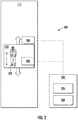
FIG. 2 is a schematic block diagram illustrating a system that may be configured in accordance with one or more embodiments of the present disclosure; -
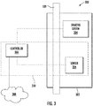
FIG. 3 is a schematic illustration of a safety actuator system in accordance with an embodiment of the present disclosure; -
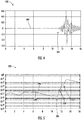
FIG. 4 is a plot of filtered sensor data that can be acquired in accordance with an embodiment of the present disclosure; -
FIG. 5 is a plot of bounce energy level that can be determined in accordance with an embodiment of the present disclosure; -
FIG. 6 is a block diagram of a vertical bounce detection dataflow in accordance with an embodiment of the present disclosure; and -
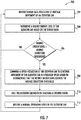
FIG. 7 illustrates a flow process in accordance with an embodiment of the present disclosure. -
FIG. 1 is a perspective view of anelevator system 101 including anelevator car 103, acounterweight 105, atension member 107, aguide rail 109, amachine 111, aposition reference system 113, and acontroller 115. Theelevator car 103 andcounterweight 105 are connected to each other by thetension member 107. Thetension member 107 may include or be configured as, for example, ropes, steel cables, and/or coated-steel belts. Thecounterweight 105 is configured to balance a load of theelevator car 103 and is configured to facilitate movement of theelevator car 103 concurrently and in an opposite direction with respect to thecounterweight 105 within an elevator shaft 117 (also referred to as hoistway 117) and along theguide rail 109. - The
tension member 107 engages themachine 111, which is part of an overhead structure of theelevator system 101. Themachine 111 is configured to control movement between theelevator car 103 and thecounterweight 105. Theposition reference system 113 may be mounted on a fixed part at the top of theelevator shaft 117, such as on a support or guide rail, and may be configured to provide position signals related to a position of theelevator car 103 within theelevator shaft 117. In other embodiments, theposition reference system 113 may be directly mounted to a moving component of themachine 111, or may be located in other positions and/or configurations as known in the art. Theposition reference system 113 can be any device or mechanism for monitoring a position of an elevator car and/or counter weight, as known in the art. For example, without limitation, theposition reference system 113 can be an encoder, sensor, or other system and can include velocity sensing, absolute position sensing, etc., as will be appreciated by those of skill in the art. - The
controller 115 is located, as shown, in acontroller room 121 of theelevator shaft 117 and is configured to control the operation of theelevator system 101, and particularly theelevator car 103. For example, thecontroller 115 may provide drive signals to themachine 111 to control the acceleration, deceleration, leveling, stopping, etc. of theelevator car 103. Thecontroller 115 may also be configured to receive position signals from theposition reference system 113. When moving up or down within theelevator shaft 117 alongguide rail 109, theelevator car 103 may stop at one or more landings 125 (e.g., floors) as controlled by thecontroller 115. Although shown in acontroller room 121, those of skill in the art will appreciate that thecontroller 115 can be located and/or configured in other locations or positions within theelevator system 101. - The
machine 111 may include a motor or similar driving mechanism. In accordance with embodiments of the disclosure, themachine 111 is configured to include an electrically driven motor. The power supply for the motor may be any power source, including a power grid, which, in combination with other components, is supplied to the motor. Themachine 111 may include a traction sheave that imparts force totension member 107 to move theelevator car 103 withinelevator shaft 117. - Although shown and described with a roping system including
tension member 107, elevator systems that employ other methods and mechanisms of moving an elevator car within an elevator shaft may employ embodiments of the present disclosure. For example, embodiments may be employed in ropeless elevator systems using a linear motor to impart motion to an elevator car.FIG. 1 is merely a non-limiting example presented for illustrative and explanatory purposes. - Turning now to
FIG. 2 , a schematic illustration of a verticalbounce detection system 200 in an example embodiment of the present disclosure is shown. Acontroller 202 of the verticalbounce detection system 200 is an example of a vertical bounce detection controller that interfaces with at least onesensor 204 operable to detect vertical movement ofelevator car 103 in ahoistway 117 of an elevator system, such aselevator system 101 ofFIG. 1 . Vertical bouncing of theelevator car 103 may be induced by movement of at least one item orperson 205 within theelevator car 103, such as theperson 205 jumping within theelevator car 103. Thecontroller 202 can be an embodiment of thecontroller 115 ofFIG. 1 or may be a separate device that interfaces withcontroller 115. Thecontroller 202 includes aprocessing system 206 communicatively coupled to the at least onesensor 204 and amemory system 208 having a plurality of instructions stored thereon. The at least onesensor 204 may be located within theelevator car 103 and/or otherwise be coupled to the elevator car 103 (e.g., externally attached to the elevator car 103). The at least onesensor 204 can include, for example, one or more of: an accelerometer, a velocity sensor, or a position sensor. Thecontroller 202 can be located within theelevator car 103 or may be external to theelevator car 103, including any communication network accessible location, such as in the cloud. - The
processing system 206 may be but is not limited to a single-processor or multi-processor system of any of a wide array of possible architectures, including field programmable gate array (FPGA), central processing unit (CPU), application specific integrated circuits (ASIC), digital signal processor (DSP) or graphics processing unit (GPU) hardware arranged homogenously or heterogeneously. Thememory system 208 may be a storage device such as, for example, a random access memory (RAM), read only memory (ROM), or other electronic, optical, magnetic or any other computer readable storage medium configured to store executable instructions in a non-transitory form. In some embodiments, all or a portion of the processing described in reference tocontroller 202 can be performed using analog circuits. - The
controller 202 may control movement of theelevator car 103 by commanding themachine 111 ofFIG. 1 to raise or lower theelevator car 103 to a desired floor. The desired floor may be one of thelandings 125 ofFIG. 1 , where a call button was pressed, may be selected through a user interface (not depicted) of theelevator car 103, or otherwise dispatched. Although only a single instance of theelevator car 103 is depicted in the example ofFIG. 2 , it will be understood that groups ofelevator cars 103 may exist within the same building/structure. - When executed by the
processing system 206, instructions stored on thememory system 208 cause the verticalbounce detection system 200 to determine a bounce energy level of theelevator car 103 based on a plurality of sensor data from the at least onesensor 204, compare the bounce energy level to a bounce condition threshold, and command a speed reduction of theelevator car 103 to continue movement of theelevator car 103 at a reduced speed based on the bounce energy level exceeding the bounce condition threshold. Further details are provided with respect toFIGS. 3-7 . - Referring to
FIG. 3 , asafety actuator system 300 is depicted that includes asafety actuator 302 operable to apply a braking force to an element of theelevator system 101 ofFIG. 1 , such as theguide rail 109 or a component of themachine 111 ofFIG. 1 , for example. Thesafety actuator 302 can be coupled to theelevator car 103 ofFIGS. 1 and2 . In the example ofFIG. 3 ,sensor 204 is part of thesafety actuator 302 along with abraking system 304 which may include brake elements and/or activation magnets. Acontroller 306 can include all or a portion of the controller 202 (FIG. 2 ) of the verticalbounce detection system 200. Further, thecontroller 306 can be a local control of thesafety actuator 302. For example, thecontroller 306 may only include sensor monitoring and braking actuation functions for thesafety actuator 302, while other control functions of theelevator car 103 are managed by thecontroller 115 and/orcontroller 202 ofFIGS. 1 and2 . Thecontroller 306 can be configured to trigger thebraking system 304 to engage theguide rail 109 responsive to detecting an over-speed condition based on sensor data from thesensor 204 of thesafety actuator 302. In some embodiments, thecontroller 306 also monitors thesensor 204 for vertical bounce and may command a speed reduction of theelevator car 103 by outputting a speed reduction request on acommunication interface 308 or directly command the speed reduction if incorporated in thecontroller 115 ofFIG. 1 . Thecommunication interface 308 may include wired and/or wireless communication support, such as a communication bus accessible bycontrollers machine 111 ofFIG. 1 . - The
safety actuator 302 may be an electronic safety actuator or can be implemented using any type of over-speed governor components and need not be limited to an electronic system. For example, thebraking system 304 can use flyballs or flyweights that extend when a predetermined force level is applied to actuate a motor brake to apply a braking force. One or more switches (not depicted) can be used to trigger braking and/or depowering of themachine 111 ofFIG. 1 as part of over-speed protection. In some embodiments of thesafety actuator 302, the sensor orsensors 204 may be located external to thesafety actuator 302, such as in a mechanical over-speed governor implementation. - Referring now to
FIGS. 4-6 , a block diagram of a verticalbounce detection dataflow 600 is depicted inFIG. 6 that can be implemented bycontroller 202 and/orcontroller 306 ofFIGS. 2 and3 . For example, the verticalbounce detection dataflow 600 can be implemented using analog and/or digital circuitry. The verticalbounce detection dataflow 600 is illustrated as an example where asensor 204 ofFIGS. 2 and3 provide acceleration data assensor data 602 to abandpass filter 604 to produce filteredsensor data 606. An example of filteredsensor data 606 is depicted inplot 400 ofFIG. 4 as filteredsensor data 402. As one example, corner frequencies of thebandpass filter 604 can be set to extract content between one and four Hertz to detect low frequency bouncing. The frequency range of thebandpass filter 604 can be tuned depending upon frequencies of interest, such as resonant frequencies of components of theelevator system 101 ofFIG. 1 . In embodiments where thesensor 204 is not an accelerometer, additional processing steps may be used to convert thesensor data 602 into acceleration data. For instance, a derivative operation can be performed on a velocity signal to produce an acceleration signal, or a second-derivative operation can be performed on a position signal. Other signal variations and corresponding operations are contemplated. - In some embodiments, a function, such as a
squaring function 608, can be applied to the filteredsensor data 606 to approximate an energy signal as anoutput 610, which may be further filtered by alowpass filter 612 to produce abounce energy level 614. In some embodiments, thelowpass filter 612 can be implemented as a lossy integrator, for instance, in an operational amplifier based circuit. Thelowpass filter 612 can be used to further attenuate higher frequency noise and/or provide anti-aliasing for digital sampling. An example of thebounce energy level 614 is depicted in theplot 500 ofFIG. 5 as abounce energy level 502 with respect to time. Thebounce energy level 614 can be compared by acomparator 616 with respect to abounce condition threshold 618 to produce avertical bouncing determination 620. Thebounce condition threshold 618 can vary from system to system and may need to be specifically calibrated for each elevator car installation, due to custom tuning of systems, as well as dynamics parts contributing to the different characteristics of bounce conditions for various installations, such as belts vs. ropes and the like. Thebounce condition threshold 618 can be set to a value that is determined to be as low as possible without causing false trips during normal operation (i.e., no bouncing conditions), which can result in the greatest possible time available for communicating the detected bounce condition before an emergency stop is unavoidable. - In embodiments, the
bounce condition threshold 618 can be set to trip a speed reduction of theelevator car 103 prior to crossing an over-speed condition operable to apply a braking force by engaging thebraking system 304 of thesafety actuator 302 ofFIG. 3 . For instance, with respect to time, a bouncing event can start attime 404 ofFIG. 4 , which maps totime 504 ofFIG. 5 . Athreshold level 506 ofFIG. 5 is an example of thebounce condition threshold 618, where thebounce energy level 502 crosses thethreshold level 506 attime 508 and may otherwise cross an over-speed condition at time 510 if the speed of theelevator car 103 is not reduced. Upon a speed reduction, e.g., 1/3 of the normal operating speed, the addition of vertical bouncing energy by aperson 205 ofFIG. 2 may be insufficient to cross an over-speed condition, and thus an otherwise unneeded activation of thesafety actuator 302 ofFIG. 3 is avoided. Speed reduction values and ranges can be determined based on system and/or installation characteristics to optimize operation, as well as preventing unnecessary emergency stops even after speed reduction. Examples of speed reductions include 1/3, 1/5, and/or 2/3 speed reductions of the normal operating speed, with other reduction values contemplated. - Turning now to
FIG. 7 , aflow process 700 in accordance with an embodiment of the present disclosure is shown.Flow process 700 may incorporate additional or alternative steps without departing from the scope of the present disclosure. Theflow process 700 may be performed by one or more of thecontroller FIGS. 1-3 as a method of vertical bounce detection in an elevator system, such as theelevator system 101 ofFIG. 1 . Accordingly,flow process 700 is described in reference toFIGS. 1-7 . For purposes of explanation, theflow process 700 is described with respect tocontroller 202 ofFIG. 2 . - At
block 702,controller 202 receives a plurality ofsensor data 602 indicative of vertical movement of anelevator car 103 in ahoistway 117 of theelevator system 101. Atblock 704,controller 202 determines abounce energy level 614 of theelevator car 103 based on thesensor data 602. Thebounce energy level 614 may be determined by applying abandpass filter 604 to thesensor data 602, applying asquaring function 608 to an output (e.g., filtered sensor data 606) of thebandpass filter 604, and applying alowpass filter 612 to anoutput 610 of the squaringfunction 608. - At
block 706,controller 202 can compare thebounce energy level 614 to abounce condition threshold 618, for instance, usingcomparator 616. Atblock 708,controller 202 can command a speed reduction of theelevator car 103 to continue movement of theelevator car 103 at a reduced speed based on thebounce energy level 614 exceeding thebounce condition threshold 618. The speed reduction of theelevator car 103 can be commanded by outputting a speed reduction request on a communication interface, such as thecommunication interface 308. - At
block 710, theelevator car 103 can be halted based on reaching a desired floor or landing 125. Atblock 712,controller 202 can restore a normal operating speed of theelevator car 103 after a speed restoration condition is met, such as requesting travel to a next desired floor after halting. As another example of a speed restoration condition, if the vertical bouncing is reduced by a predetermined amount after the speed reduction of theelevator car 103, thecontroller 202 can increase the speed of theelevator car 103 prior to reaching a desired floor, for instance, in a high-rise building application. Further, if vertical bouncing is detected while theelevator car 103 is stationary, requesting travel to a next desired floor may not be permitted, which is an example of a not meeting a speed restoration condition due to new/continued detection of vertical bouncing. - As described above, embodiments can be in the form of processor-implemented processes and devices for practicing those processes, such as a processor. Embodiments can also be in the form of computer program code containing instructions embodied in tangible media, such as network cloud storage, SD cards, flash drives, floppy diskettes, CD ROMs, hard drives, or any other computer-readable storage medium, wherein, when the computer program code is loaded into and executed by a computer, the computer becomes a device for practicing the embodiments. Embodiments can also be in the form of computer program code, for example, whether stored in a storage medium, loaded into and/or executed by a computer, or transmitted over some transmission medium, loaded into and/or executed by a computer, or transmitted over some transmission medium, such as over electrical wiring or cabling, through fiber optics, or via electromagnetic radiation, wherein, when the computer program code is loaded into an executed by a computer, the computer becomes an device for practicing the embodiments. When implemented on a general-purpose microprocessor, the computer program code segments configure the microprocessor to create specific logic circuits.
- The term "about" is intended to include the degree of error associated with measurement of the particular quantity and/or manufacturing tolerances based upon the equipment available at the time of filing the application.
- The terminology used herein is for the purpose of describing particular embodiments only and is not intended to be limiting of the present disclosure. As used herein, the singular forms "a", "an" and "the" are intended to include the plural forms as well, unless the context clearly indicates otherwise. It will be further understood that the terms "comprises" and/or "comprising," when used in this specification, specify the presence of stated features, integers, steps, operations, elements, and/or components, but do not preclude the presence or addition of one or more other features, integers, steps, operations, element components, and/or groups thereof.
- Those of skill in the art will appreciate that various example embodiments are shown and described herein, each having certain features in the particular embodiments, but the present disclosure is not thus limited. Rather, the present disclosure can be modified to incorporate any number of variations, alterations, substitutions, combinations, sub-combinations, or equivalent arrangements not heretofore described, but which are commensurate with the scope of the present disclosure. Additionally, while various embodiments of the present disclosure have been described, it is to be understood that aspects of the present disclosure may include only some of the described embodiments. Accordingly, the present disclosure is not to be seen as limited by the foregoing description, but is only limited by the scope of the appended claims.
Claims (15)
- A vertical bounce detection system of an elevator system, the vertical bounce detection system comprising:at least one sensor operable to detect vertical movement of an elevator car in a hoistway of the elevator system;a processing system communicatively coupled to the at least one sensor; anda memory system having a plurality of instructions stored thereon that, when executed by the processing system, cause the vertical bounce detection system to:determine a bounce energy level of the elevator car based on sensor data from the at least one sensor;compare the bounce energy level to a bounce condition threshold; andcommand a speed reduction of the elevator car to continue movement of the elevator car at a reduced speed based on determining that the bounce energy level exceeds the bounce condition threshold.
- The vertical bounce detection system of claim 1, wherein the at least one sensor, the processing system, and the memory system are components of a safety actuator operable to apply a braking force to an element of the elevator system.
- The vertical bounce detection system of claim 2, wherein the bounce condition threshold is set to trip the speed reduction prior to crossing an over-speed condition operable to apply the braking force by engaging a braking system of the safety actuator.
- The vertical bounce detection system of any preceding claim, wherein the speed reduction of the elevator car is commanded by outputting a speed reduction request on a communication interface.
- The vertical bounce detection system of any preceding claim, wherein the vertical bounce detection system is configured to restore a normal operating speed of the elevator car after a speed restoration condition is met; and optionally wherein the speed restoration condition comprises one or more of: a request to travel to a next desired floor after halting the elevator car, and a confirmation that vertical bouncing is reduced after the speed reduction of the elevator car.
- The vertical bounce detection system of any preceding claim, wherein the vertical bounce detection system is configured to apply a bandpass filter to the sensor data and a lowpass filter to an output of the bandpass filter.
- The vertical bounce detection system of claim 6, wherein the sensor data comprises acceleration data and the vertical bounce detection system is configured to apply a squaring function to the output of the bandpass filter prior to applying the lowpass filter to determine the bounce energy level based on the acceleration data; and optionally wherein the lowpass filter comprises an integrator.
- The vertical bounce detection system of any preceding claim, wherein the at least one sensor comprises one or more of: an accelerometer, a velocity sensor, or a position sensor.
- A method of vertical bounce detection in an elevator system, the method comprising:receiving sensor data indicative of vertical movement of an elevator car in a hoistway of the elevator system;determining a bounce energy level of the elevator car based on the sensor data;comparing the bounce energy level to a bounce condition threshold; andcommanding a speed reduction of the elevator car to continue movement of the elevator car at a reduced speed based on determining that the bounce energy level exceeds the bounce condition threshold.
- The method of claim 9, wherein the method is performed by a safety actuator operable to apply a braking force to an element of the elevator system; and optionally wherein the bounce condition threshold is set to trip the speed reduction prior to crossing an over-speed condition operable to apply the braking force by engaging a braking system of the safety actuator.
- The method of claim 9 or 10, wherein the speed reduction of the elevator car is commanded by outputting a speed reduction request on a communication interface.
- The method of any of claims 9 to 11, further comprising:
restoring a normal operating speed of the elevator car after a speed restoration condition is met; and optionally wherein the speed restoration condition comprises one or more of: a request to travel to a next desired floor after halting the elevator car, and a confirmation that vertical bouncing is reduced after the speed reduction of the elevator car. - The method of any of claims 9 to 12, further comprising:applying a bandpass filter to the sensor data; andapplying a lowpass filter to an output of the bandpass filter.
- The method of claim 13, wherein the sensor data comprises acceleration data and further comprising:
applying a squaring function to the output of the bandpass filter prior to applying the lowpass filter to determine the bounce energy level based on the acceleration data; and optionally wherein the lowpass filter comprises an integrator. - The method of any of claims 9 to 14, wherein the sensor data is received from one or more of: an accelerometer, a velocity sensor, or a position sensor.
Applications Claiming Priority (1)
| Application Number | Priority Date | Filing Date | Title |
|---|---|---|---|
| US15/968,916 US11117781B2 (en) | 2018-05-02 | 2018-05-02 | Vertical bounce detection and mitigation |
Publications (2)
| Publication Number | Publication Date |
|---|---|
| EP3643670A1 true EP3643670A1 (en) | 2020-04-29 |
| EP3643670B1 EP3643670B1 (en) | 2023-02-22 |
Family
ID=66379815
Family Applications (1)
| Application Number | Title | Priority Date | Filing Date |
|---|---|---|---|
| EP19172332.9A Active EP3643670B1 (en) | 2018-05-02 | 2019-05-02 | Vertical bounce detection and mitigation |
Country Status (3)
| Country | Link |
|---|---|
| US (1) | US11117781B2 (en) |
| EP (1) | EP3643670B1 (en) |
| CN (1) | CN110436288B (en) |
Families Citing this family (1)
| Publication number | Priority date | Publication date | Assignee | Title |
|---|---|---|---|---|
| CN111675061B (en) * | 2020-07-02 | 2021-12-07 | 西藏洲明电子科技有限公司 | Intelligent system integrated management system |
Citations (6)
| Publication number | Priority date | Publication date | Assignee | Title |
|---|---|---|---|---|
| JPH0967071A (en) * | 1995-08-31 | 1997-03-11 | Hitachi Building Syst Co Ltd | Elevator abnormal operation device |
| JPH10316319A (en) * | 1997-05-19 | 1998-12-02 | Mitsubishi Denki Bill Techno Service Kk | Swing reduction device for elevator car |
| JP2008308271A (en) * | 2007-06-13 | 2008-12-25 | Hitachi Ltd | Elevator safety equipment |
| EP2824056A1 (en) * | 2013-07-10 | 2015-01-14 | Inventio AG | Vandal-proofing of a lift assembly |
| EP2835334A1 (en) * | 2013-08-08 | 2015-02-11 | Kone Corporation | Method for controlling an elevator and elevator |
| EP3564170A1 (en) * | 2018-05-01 | 2019-11-06 | Otis Elevator Company | Elevator car control to address abnormal passenger behavior |
Family Cites Families (20)
| Publication number | Priority date | Publication date | Assignee | Title |
|---|---|---|---|---|
| US3986127A (en) * | 1975-05-27 | 1976-10-12 | The United States Of America As Represented By The Secretary Of The Air Force | Integrated feedback active filter/integrator |
| GB8610842D0 (en) * | 1986-05-02 | 1986-06-11 | Bl Tech Ltd | Suspension system |
| JPH0316319A (en) | 1989-03-29 | 1991-01-24 | Matsushita Electric Ind Co Ltd | encoder circuit |
| DE69315653T2 (en) * | 1992-09-21 | 1998-04-02 | Nippon Electric Co | Distinguishing an accident from a non-accident by analyzing the frequency components of the measured acceleration values generated during the impact |
| JPH06183660A (en) | 1992-12-04 | 1994-07-05 | Otis Elevator Co | Device for preventing nalfunction of governor of elevator |
| JPH06263358A (en) | 1993-03-16 | 1994-09-20 | Hitachi Ltd | Governor malfunction prevention device for elevator |
| JP3329080B2 (en) * | 1994-07-29 | 2002-09-30 | 日本電気株式会社 | Vehicle collision determination method and collision determination device |
| US5750945A (en) | 1996-06-03 | 1998-05-12 | Otis Elevator Company | Active elevator hitch |
| JPH1053378A (en) | 1996-06-07 | 1998-02-24 | Otis Elevator Co | Elevator speed control circuit |
| JPH11139709A (en) | 1997-11-13 | 1999-05-25 | Hitachi Building Systems Co Ltd | Elevator emergency stop device |
| ES2169988B1 (en) | 2000-03-17 | 2003-10-01 | Otis Elevator Co | CONTROLLER DEVICE OF THE DRIVER OF THE SPEED LIMITER OF AN ELEVATOR. |
| SG126045A1 (en) | 2005-03-24 | 2006-10-30 | Inventio Ag | Elevator with vertical vibration compensation |
| JP2009215057A (en) | 2008-03-13 | 2009-09-24 | Toshiba Elevator Co Ltd | Compulsory deceleration control system of elevator |
| JP5649808B2 (en) * | 2009-01-28 | 2015-01-07 | ソニー株式会社 | Information processing apparatus, information processing method, and program |
| JP2012520811A (en) | 2009-03-16 | 2012-09-10 | オーチス エレベータ カンパニー | Over acceleration and over speed detection and processing system |
| ES2672638T3 (en) | 2009-03-16 | 2018-06-15 | Otis Elevator Company | Elevator over-acceleration and over-speed protection system |
| US8631909B2 (en) | 2009-03-16 | 2014-01-21 | Otis Elevator Company | Electromagnetic safety trigger |
| CN104395215B (en) | 2012-06-20 | 2016-09-21 | 奥的斯电梯公司 | The vertical oscillation of active attenuation lift car |
| CN104981423A (en) | 2013-02-12 | 2015-10-14 | 因温特奥股份公司 | Damping of vertical vibrations of an elevator car of an elevator system |
| JP6307406B2 (en) | 2014-09-26 | 2018-04-04 | 株式会社日立製作所 | Elevator equipment |
-
2018
- 2018-05-02 US US15/968,916 patent/US11117781B2/en not_active Expired - Fee Related
-
2019
- 2019-05-02 EP EP19172332.9A patent/EP3643670B1/en active Active
- 2019-05-06 CN CN201910371497.0A patent/CN110436288B/en not_active Expired - Fee Related
Patent Citations (6)
| Publication number | Priority date | Publication date | Assignee | Title |
|---|---|---|---|---|
| JPH0967071A (en) * | 1995-08-31 | 1997-03-11 | Hitachi Building Syst Co Ltd | Elevator abnormal operation device |
| JPH10316319A (en) * | 1997-05-19 | 1998-12-02 | Mitsubishi Denki Bill Techno Service Kk | Swing reduction device for elevator car |
| JP2008308271A (en) * | 2007-06-13 | 2008-12-25 | Hitachi Ltd | Elevator safety equipment |
| EP2824056A1 (en) * | 2013-07-10 | 2015-01-14 | Inventio AG | Vandal-proofing of a lift assembly |
| EP2835334A1 (en) * | 2013-08-08 | 2015-02-11 | Kone Corporation | Method for controlling an elevator and elevator |
| EP3564170A1 (en) * | 2018-05-01 | 2019-11-06 | Otis Elevator Company | Elevator car control to address abnormal passenger behavior |
Also Published As
| Publication number | Publication date |
|---|---|
| EP3643670B1 (en) | 2023-02-22 |
| CN110436288B (en) | 2021-09-07 |
| US20190337756A1 (en) | 2019-11-07 |
| US11117781B2 (en) | 2021-09-14 |
| CN110436288A (en) | 2019-11-12 |
Similar Documents
| Publication | Publication Date | Title |
|---|---|---|
| US10196234B2 (en) | Method for controlling unintended vertical speed and acceleration of an elevator | |
| US9776827B2 (en) | Elevator system including monitoring arrangement to activate multiple emergency braking procedures associated with different decelerations and method of operating the same | |
| CN104276474B (en) | The security system of elevator | |
| CN104718148B (en) | The safety device of lift facility | |
| US11554933B2 (en) | Elevator | |
| CN102348627A (en) | Electromagnetic safety trigger | |
| US20190002238A1 (en) | Elevator accelerometer sensor data usage | |
| EP3628622A1 (en) | Validation of elevator call passenger boarding | |
| CN106256746A (en) | Control apparatus and method | |
| CN114104911A (en) | Elevator system | |
| US20200031615A1 (en) | Capacity shifting between partially-overlapping elevator groups | |
| EP3643670B1 (en) | Vertical bounce detection and mitigation | |
| CN110304517B (en) | Method and system for reducing false actuation of safety brake in elevator system | |
| EP3828115B1 (en) | Emergency stop system for elevator | |
| CN111847154B (en) | Solutions for operating elevators | |
| US20190300328A1 (en) | Super group dispatching | |
| US12297079B2 (en) | Roller speed sensor with magnets and sensors | |
| EP3878787B1 (en) | Managing elevator call assignments in response to elevator door reversals | |
| HK40037910A (en) | Elevator | |
| HK40032485A (en) | A solution for operating an elevator | |
| HK1124302A1 (en) | Method and device for detecting the speed of moving objects | |
| HK1135080B (en) | An elevator system and a method of operating the elevator system | |
| HK1124302B (en) | Method and device for detecting the speed of moving objects | |
| HK1166771B (en) | Electromagnetic safety trigger | |
| HK1135080A1 (en) | An elevator system and a method of operating the elevator system |
Legal Events
| Date | Code | Title | Description |
|---|---|---|---|
| PUAI | Public reference made under article 153(3) epc to a published international application that has entered the european phase |
Free format text: ORIGINAL CODE: 0009012 |
|
| STAA | Information on the status of an ep patent application or granted ep patent |
Free format text: STATUS: THE APPLICATION HAS BEEN PUBLISHED |
|
| AK | Designated contracting states |
Kind code of ref document: A1 Designated state(s): AL AT BE BG CH CY CZ DE DK EE ES FI FR GB GR HR HU IE IS IT LI LT LU LV MC MK MT NL NO PL PT RO RS SE SI SK SM TR |
|
| AX | Request for extension of the european patent |
Extension state: BA ME |
|
| STAA | Information on the status of an ep patent application or granted ep patent |
Free format text: STATUS: REQUEST FOR EXAMINATION WAS MADE |
|
| 17P | Request for examination filed |
Effective date: 20201027 |
|
| RBV | Designated contracting states (corrected) |
Designated state(s): AL AT BE BG CH CY CZ DE DK EE ES FI FR GB GR HR HU IE IS IT LI LT LU LV MC MK MT NL NO PL PT RO RS SE SI SK SM TR |
|
| GRAP | Despatch of communication of intention to grant a patent |
Free format text: ORIGINAL CODE: EPIDOSNIGR1 |
|
| STAA | Information on the status of an ep patent application or granted ep patent |
Free format text: STATUS: GRANT OF PATENT IS INTENDED |
|
| INTG | Intention to grant announced |
Effective date: 20210506 |
|
| GRAJ | Information related to disapproval of communication of intention to grant by the applicant or resumption of examination proceedings by the epo deleted |
Free format text: ORIGINAL CODE: EPIDOSDIGR1 |
|
| STAA | Information on the status of an ep patent application or granted ep patent |
Free format text: STATUS: REQUEST FOR EXAMINATION WAS MADE |
|
| STAA | Information on the status of an ep patent application or granted ep patent |
Free format text: STATUS: EXAMINATION IS IN PROGRESS |
|
| INTC | Intention to grant announced (deleted) | ||
| 17Q | First examination report despatched |
Effective date: 20211007 |
|
| GRAP | Despatch of communication of intention to grant a patent |
Free format text: ORIGINAL CODE: EPIDOSNIGR1 |
|
| STAA | Information on the status of an ep patent application or granted ep patent |
Free format text: STATUS: GRANT OF PATENT IS INTENDED |
|
| INTG | Intention to grant announced |
Effective date: 20221011 |
|
| RIN1 | Information on inventor provided before grant (corrected) |
Inventor name: MARVIN, DARYL J. Inventor name: WROBLEWSKI, MARCIN |
|
| GRAS | Grant fee paid |
Free format text: ORIGINAL CODE: EPIDOSNIGR3 |
|
| GRAA | (expected) grant |
Free format text: ORIGINAL CODE: 0009210 |
|
| STAA | Information on the status of an ep patent application or granted ep patent |
Free format text: STATUS: THE PATENT HAS BEEN GRANTED |
|
| AK | Designated contracting states |
Kind code of ref document: B1 Designated state(s): AL AT BE BG CH CY CZ DE DK EE ES FI FR GB GR HR HU IE IS IT LI LT LU LV MC MK MT NL NO PL PT RO RS SE SI SK SM TR |
|
| REG | Reference to a national code |
Ref country code: GB Ref legal event code: FG4D |
|
| REG | Reference to a national code |
Ref country code: CH Ref legal event code: EP |
|
| REG | Reference to a national code |
Ref country code: DE Ref legal event code: R096 Ref document number: 602019025435 Country of ref document: DE |
|
| REG | Reference to a national code |
Ref country code: AT Ref legal event code: REF Ref document number: 1549397 Country of ref document: AT Kind code of ref document: T Effective date: 20230315 Ref country code: IE Ref legal event code: FG4D |
|
| REG | Reference to a national code |
Ref country code: LT Ref legal event code: MG9D |
|
| REG | Reference to a national code |
Ref country code: NL Ref legal event code: MP Effective date: 20230222 |
|
| REG | Reference to a national code |
Ref country code: AT Ref legal event code: MK05 Ref document number: 1549397 Country of ref document: AT Kind code of ref document: T Effective date: 20230222 |
|
| PG25 | Lapsed in a contracting state [announced via postgrant information from national office to epo] |
Ref country code: RS Free format text: LAPSE BECAUSE OF FAILURE TO SUBMIT A TRANSLATION OF THE DESCRIPTION OR TO PAY THE FEE WITHIN THE PRESCRIBED TIME-LIMIT Effective date: 20230222 Ref country code: PT Free format text: LAPSE BECAUSE OF FAILURE TO SUBMIT A TRANSLATION OF THE DESCRIPTION OR TO PAY THE FEE WITHIN THE PRESCRIBED TIME-LIMIT Effective date: 20230622 Ref country code: NO Free format text: LAPSE BECAUSE OF FAILURE TO SUBMIT A TRANSLATION OF THE DESCRIPTION OR TO PAY THE FEE WITHIN THE PRESCRIBED TIME-LIMIT Effective date: 20230522 Ref country code: NL Free format text: LAPSE BECAUSE OF FAILURE TO SUBMIT A TRANSLATION OF THE DESCRIPTION OR TO PAY THE FEE WITHIN THE PRESCRIBED TIME-LIMIT Effective date: 20230222 Ref country code: LV Free format text: LAPSE BECAUSE OF FAILURE TO SUBMIT A TRANSLATION OF THE DESCRIPTION OR TO PAY THE FEE WITHIN THE PRESCRIBED TIME-LIMIT Effective date: 20230222 Ref country code: LT Free format text: LAPSE BECAUSE OF FAILURE TO SUBMIT A TRANSLATION OF THE DESCRIPTION OR TO PAY THE FEE WITHIN THE PRESCRIBED TIME-LIMIT Effective date: 20230222 Ref country code: HR Free format text: LAPSE BECAUSE OF FAILURE TO SUBMIT A TRANSLATION OF THE DESCRIPTION OR TO PAY THE FEE WITHIN THE PRESCRIBED TIME-LIMIT Effective date: 20230222 Ref country code: ES Free format text: LAPSE BECAUSE OF FAILURE TO SUBMIT A TRANSLATION OF THE DESCRIPTION OR TO PAY THE FEE WITHIN THE PRESCRIBED TIME-LIMIT Effective date: 20230222 Ref country code: AT Free format text: LAPSE BECAUSE OF FAILURE TO SUBMIT A TRANSLATION OF THE DESCRIPTION OR TO PAY THE FEE WITHIN THE PRESCRIBED TIME-LIMIT Effective date: 20230222 |
|
| PG25 | Lapsed in a contracting state [announced via postgrant information from national office to epo] |
Ref country code: SE Free format text: LAPSE BECAUSE OF FAILURE TO SUBMIT A TRANSLATION OF THE DESCRIPTION OR TO PAY THE FEE WITHIN THE PRESCRIBED TIME-LIMIT Effective date: 20230222 Ref country code: PL Free format text: LAPSE BECAUSE OF FAILURE TO SUBMIT A TRANSLATION OF THE DESCRIPTION OR TO PAY THE FEE WITHIN THE PRESCRIBED TIME-LIMIT Effective date: 20230222 Ref country code: IS Free format text: LAPSE BECAUSE OF FAILURE TO SUBMIT A TRANSLATION OF THE DESCRIPTION OR TO PAY THE FEE WITHIN THE PRESCRIBED TIME-LIMIT Effective date: 20230622 Ref country code: GR Free format text: LAPSE BECAUSE OF FAILURE TO SUBMIT A TRANSLATION OF THE DESCRIPTION OR TO PAY THE FEE WITHIN THE PRESCRIBED TIME-LIMIT Effective date: 20230523 Ref country code: FI Free format text: LAPSE BECAUSE OF FAILURE TO SUBMIT A TRANSLATION OF THE DESCRIPTION OR TO PAY THE FEE WITHIN THE PRESCRIBED TIME-LIMIT Effective date: 20230222 |
|
| PG25 | Lapsed in a contracting state [announced via postgrant information from national office to epo] |
Ref country code: SM Free format text: LAPSE BECAUSE OF FAILURE TO SUBMIT A TRANSLATION OF THE DESCRIPTION OR TO PAY THE FEE WITHIN THE PRESCRIBED TIME-LIMIT Effective date: 20230222 Ref country code: RO Free format text: LAPSE BECAUSE OF FAILURE TO SUBMIT A TRANSLATION OF THE DESCRIPTION OR TO PAY THE FEE WITHIN THE PRESCRIBED TIME-LIMIT Effective date: 20230222 Ref country code: EE Free format text: LAPSE BECAUSE OF FAILURE TO SUBMIT A TRANSLATION OF THE DESCRIPTION OR TO PAY THE FEE WITHIN THE PRESCRIBED TIME-LIMIT Effective date: 20230222 Ref country code: DK Free format text: LAPSE BECAUSE OF FAILURE TO SUBMIT A TRANSLATION OF THE DESCRIPTION OR TO PAY THE FEE WITHIN THE PRESCRIBED TIME-LIMIT Effective date: 20230222 Ref country code: CZ Free format text: LAPSE BECAUSE OF FAILURE TO SUBMIT A TRANSLATION OF THE DESCRIPTION OR TO PAY THE FEE WITHIN THE PRESCRIBED TIME-LIMIT Effective date: 20230222 |
|
| REG | Reference to a national code |
Ref country code: DE Ref legal event code: R097 Ref document number: 602019025435 Country of ref document: DE |
|
| PG25 | Lapsed in a contracting state [announced via postgrant information from national office to epo] |
Ref country code: SK Free format text: LAPSE BECAUSE OF FAILURE TO SUBMIT A TRANSLATION OF THE DESCRIPTION OR TO PAY THE FEE WITHIN THE PRESCRIBED TIME-LIMIT Effective date: 20230222 |
|
| PLBE | No opposition filed within time limit |
Free format text: ORIGINAL CODE: 0009261 |
|
| REG | Reference to a national code |
Ref country code: CH Ref legal event code: PL |
|
| STAA | Information on the status of an ep patent application or granted ep patent |
Free format text: STATUS: NO OPPOSITION FILED WITHIN TIME LIMIT |
|
| PG25 | Lapsed in a contracting state [announced via postgrant information from national office to epo] |
Ref country code: MC Free format text: LAPSE BECAUSE OF FAILURE TO SUBMIT A TRANSLATION OF THE DESCRIPTION OR TO PAY THE FEE WITHIN THE PRESCRIBED TIME-LIMIT Effective date: 20230222 |
|
| GBPC | Gb: european patent ceased through non-payment of renewal fee |
Effective date: 20230522 |
|
| REG | Reference to a national code |
Ref country code: BE Ref legal event code: MM Effective date: 20230531 |
|
| 26N | No opposition filed |
Effective date: 20231123 |
|
| PG25 | Lapsed in a contracting state [announced via postgrant information from national office to epo] |
Ref country code: SI Free format text: LAPSE BECAUSE OF FAILURE TO SUBMIT A TRANSLATION OF THE DESCRIPTION OR TO PAY THE FEE WITHIN THE PRESCRIBED TIME-LIMIT Effective date: 20230222 Ref country code: MC Free format text: LAPSE BECAUSE OF FAILURE TO SUBMIT A TRANSLATION OF THE DESCRIPTION OR TO PAY THE FEE WITHIN THE PRESCRIBED TIME-LIMIT Effective date: 20230222 Ref country code: LU Free format text: LAPSE BECAUSE OF NON-PAYMENT OF DUE FEES Effective date: 20230502 Ref country code: LI Free format text: LAPSE BECAUSE OF NON-PAYMENT OF DUE FEES Effective date: 20230531 Ref country code: CH Free format text: LAPSE BECAUSE OF NON-PAYMENT OF DUE FEES Effective date: 20230531 |
|
| REG | Reference to a national code |
Ref country code: IE Ref legal event code: MM4A |
|
| PG25 | Lapsed in a contracting state [announced via postgrant information from national office to epo] |
Ref country code: IE Free format text: LAPSE BECAUSE OF NON-PAYMENT OF DUE FEES Effective date: 20230502 |
|
| PG25 | Lapsed in a contracting state [announced via postgrant information from national office to epo] |
Ref country code: IE Free format text: LAPSE BECAUSE OF NON-PAYMENT OF DUE FEES Effective date: 20230502 Ref country code: GB Free format text: LAPSE BECAUSE OF NON-PAYMENT OF DUE FEES Effective date: 20230522 |
|
| PG25 | Lapsed in a contracting state [announced via postgrant information from national office to epo] |
Ref country code: IT Free format text: LAPSE BECAUSE OF FAILURE TO SUBMIT A TRANSLATION OF THE DESCRIPTION OR TO PAY THE FEE WITHIN THE PRESCRIBED TIME-LIMIT Effective date: 20230222 Ref country code: BE Free format text: LAPSE BECAUSE OF NON-PAYMENT OF DUE FEES Effective date: 20230531 |
|
| PGFP | Annual fee paid to national office [announced via postgrant information from national office to epo] |
Ref country code: DE Payment date: 20240418 Year of fee payment: 6 |
|
| PGFP | Annual fee paid to national office [announced via postgrant information from national office to epo] |
Ref country code: FR Payment date: 20240418 Year of fee payment: 6 |
|
| PG25 | Lapsed in a contracting state [announced via postgrant information from national office to epo] |
Ref country code: BG Free format text: LAPSE BECAUSE OF FAILURE TO SUBMIT A TRANSLATION OF THE DESCRIPTION OR TO PAY THE FEE WITHIN THE PRESCRIBED TIME-LIMIT Effective date: 20230222 |
|
| PG25 | Lapsed in a contracting state [announced via postgrant information from national office to epo] |
Ref country code: BG Free format text: LAPSE BECAUSE OF FAILURE TO SUBMIT A TRANSLATION OF THE DESCRIPTION OR TO PAY THE FEE WITHIN THE PRESCRIBED TIME-LIMIT Effective date: 20230222 |
|
| PG25 | Lapsed in a contracting state [announced via postgrant information from national office to epo] |
Ref country code: CY Free format text: LAPSE BECAUSE OF FAILURE TO SUBMIT A TRANSLATION OF THE DESCRIPTION OR TO PAY THE FEE WITHIN THE PRESCRIBED TIME-LIMIT; INVALID AB INITIO Effective date: 20190502 |
|
| PG25 | Lapsed in a contracting state [announced via postgrant information from national office to epo] |
Ref country code: HU Free format text: LAPSE BECAUSE OF FAILURE TO SUBMIT A TRANSLATION OF THE DESCRIPTION OR TO PAY THE FEE WITHIN THE PRESCRIBED TIME-LIMIT; INVALID AB INITIO Effective date: 20190502 |
|
| REG | Reference to a national code |
Ref country code: DE Ref legal event code: R119 Ref document number: 602019025435 Country of ref document: DE |
|
| PG25 | Lapsed in a contracting state [announced via postgrant information from national office to epo] |
Ref country code: TR Free format text: LAPSE BECAUSE OF FAILURE TO SUBMIT A TRANSLATION OF THE DESCRIPTION OR TO PAY THE FEE WITHIN THE PRESCRIBED TIME-LIMIT Effective date: 20230222 |
|
| PG25 | Lapsed in a contracting state [announced via postgrant information from national office to epo] |
Ref country code: DE Free format text: LAPSE BECAUSE OF NON-PAYMENT OF DUE FEES Effective date: 20251202 |
|
| PG25 | Lapsed in a contracting state [announced via postgrant information from national office to epo] |
Ref country code: FR Free format text: LAPSE BECAUSE OF NON-PAYMENT OF DUE FEES Effective date: 20250531 |