EP3643616A1 - Vented leading-edge assembly and method for manufacturing a vented leading-edge assembly - Google Patents
Vented leading-edge assembly and method for manufacturing a vented leading-edge assembly Download PDFInfo
- Publication number
- EP3643616A1 EP3643616A1 EP19203214.2A EP19203214A EP3643616A1 EP 3643616 A1 EP3643616 A1 EP 3643616A1 EP 19203214 A EP19203214 A EP 19203214A EP 3643616 A1 EP3643616 A1 EP 3643616A1
- Authority
- EP
- European Patent Office
- Prior art keywords
- bay
- spar
- edge assembly
- leading
- channel sidewalls
- Prior art date
- Legal status (The legal status is an assumption and is not a legal conclusion. Google has not performed a legal analysis and makes no representation as to the accuracy of the status listed.)
- Granted
Links
Images



Classifications
-
- B—PERFORMING OPERATIONS; TRANSPORTING
- B64—AIRCRAFT; AVIATION; COSMONAUTICS
- B64C—AEROPLANES; HELICOPTERS
- B64C21/00—Influencing air flow over aircraft surfaces by affecting boundary layer flow
- B64C21/02—Influencing air flow over aircraft surfaces by affecting boundary layer flow by use of slot, ducts, porous areas or the like
-
- B—PERFORMING OPERATIONS; TRANSPORTING
- B64—AIRCRAFT; AVIATION; COSMONAUTICS
- B64D—EQUIPMENT FOR FITTING IN OR TO AIRCRAFT; FLIGHT SUITS; PARACHUTES; ARRANGEMENT OR MOUNTING OF POWER PLANTS OR PROPULSION TRANSMISSIONS IN AIRCRAFT
- B64D15/00—De-icing or preventing icing on exterior surfaces of aircraft
- B64D15/02—De-icing or preventing icing on exterior surfaces of aircraft by ducted hot gas or liquid
- B64D15/04—Hot gas application
-
- B—PERFORMING OPERATIONS; TRANSPORTING
- B64—AIRCRAFT; AVIATION; COSMONAUTICS
- B64C—AEROPLANES; HELICOPTERS
- B64C3/00—Wings
- B64C3/26—Construction, shape, or attachment of separate skins, e.g. panels
-
- B—PERFORMING OPERATIONS; TRANSPORTING
- B64—AIRCRAFT; AVIATION; COSMONAUTICS
- B64C—AEROPLANES; HELICOPTERS
- B64C9/00—Adjustable control surfaces or members, e.g. rudders
- B64C9/14—Adjustable control surfaces or members, e.g. rudders forming slots
- B64C9/22—Adjustable control surfaces or members, e.g. rudders forming slots at the front of the wing
-
- B—PERFORMING OPERATIONS; TRANSPORTING
- B64—AIRCRAFT; AVIATION; COSMONAUTICS
- B64C—AEROPLANES; HELICOPTERS
- B64C9/00—Adjustable control surfaces or members, e.g. rudders
- B64C9/14—Adjustable control surfaces or members, e.g. rudders forming slots
- B64C9/22—Adjustable control surfaces or members, e.g. rudders forming slots at the front of the wing
- B64C9/24—Adjustable control surfaces or members, e.g. rudders forming slots at the front of the wing by single flap
-
- Y—GENERAL TAGGING OF NEW TECHNOLOGICAL DEVELOPMENTS; GENERAL TAGGING OF CROSS-SECTIONAL TECHNOLOGIES SPANNING OVER SEVERAL SECTIONS OF THE IPC; TECHNICAL SUBJECTS COVERED BY FORMER USPC CROSS-REFERENCE ART COLLECTIONS [XRACs] AND DIGESTS
- Y02—TECHNOLOGIES OR APPLICATIONS FOR MITIGATION OR ADAPTATION AGAINST CLIMATE CHANGE
- Y02T—CLIMATE CHANGE MITIGATION TECHNOLOGIES RELATED TO TRANSPORTATION
- Y02T50/00—Aeronautics or air transport
- Y02T50/40—Weight reduction
Definitions
- the invention relates to a vented leading-edge assembly, the assembly comprising: a slat comprising a bay and a top skin delimiting a portion of the bay; a spar being arranged in the slat, the spar dividing the bay in a front bay and an aft bay; and a plurality of channel sidewalls being arranged between the top skin and the spar, the plurality of channel sidewalls defining a plurality of channels between the front bay and the aft bay and a method for manufacturing a vented leading-edge assembly.
- Aircrafts flying in great heights may be subject to icing of the wings.
- the ice may form on the leading-edge of the wing.
- the leading-edge of the wing may comprise a slat.
- a common approach to prevent icing is to heat up the concerned parts with bleed air from the engines. This is not trivial since the slat body usually comprises a spar which separates the interior structure of the slat into two chambers.
- the bleed air streams out of the tube which is arranged in a front chamber of the slat.
- To lead the bleed air between the two chambers in the slat it is known to provide a special part between the upper part of the spar and the top skin of the slat. That special part comprises channels which allow the bleed air to travel from one chamber to another.
- the aft chamber of the slat may further comprise an air outlet to the outside of the slat to compensate the pressure which is increased by the inflowing bleed air.
- the upper skin of the slat comprises grooves on its inner side.
- the grooves are covered by an inner skin which is arranged between the spar and the inner side of the top skin of the slat.
- a vented leading-edge assembly comprising: a slat comprising a bay and a top skin delimiting a portion of the bay; a spar being arranged in the slat, the spar dividing the bay in a front bay and an aft bay; and a plurality of channel sidewalls being arranged between the top skin and the spar, the plurality of channel sidewalls defining a plurality of channels between the front bay and the aft bay, wherein at least a portion of the spar defines lower channel walls for the plurality of channels.
- the invention therefore provides channels which are defined by the channel sidewalls and the spar as lower channel wall for each channel.
- the top skin of the slat may provide an upper channel wall for the channels.
- the channel sidewalls are separate elements from the top skin of the slat and from the spar. Consequently, milling procedures on the slat or on the spar to provide sidewalls which are integral to the slat or the spar are avoided.
- the channel sidewalls may just be placed on the portion of spar between the spar and the top skin of the slat. This simplifies and accelerates the production of the vented leading-edge assembly. This allows a high rate production of the vented leading-edge assembly.
- milling is avoided, the production of the vented leading-edge is simple and cost-effective.
- the plurality of channel sidewalls is non-parallel to each other such that a distance between the plurality of channel sidewalls at the front bay is bigger than a distance between the plurality of channel sidewalls at the aft bay.
- the cross section of the channel reduces from the front bay to the aft bay.
- a flow of bleed air starting in the front bay will be accelerated when passing the channels in direction of the aft bay. Due to the acceleration of the bleed air flow, the flow keeps its flow direction after exiting the channel which leads the bleed air flow along the total length of the top skin. This avoids a stop or a dissipation of the bleed air flow before reaching the end of the top skin of the slat being distal to the leading-edge of the slat. Consequently, the complete top skin of the slat may be heated by the bleed air.
- the plurality of channel sidewalls is parallel.
- the channels being formed by the channel sidewalls do not accelerate the bleed air flow.
- Such channels may be provided if the pressure of the bleed air flow is sufficient to flow along the entire length of the top skin.
- leading-edge assembly comprises a plurality of fastening elements connecting the top skin to the spar through the plurality of channel sidewalls.
- That kind of connection of the plurality of channel sidewalls to the top skin and to the spar is simple and cost effective.
- the plurality of channel sidewalls is provided by a perforated strip being arranged between the top skin and the spar.
- the perforated strip may comprise a single row of perforations along the length of the strip.
- Such a perforated strip can be easily produced by stamping the row of perforations into the strip.
- the strip may be laser cut, water jet cut, electron beam cut or further cutting methods.
- the material between the perforations on the strip defines the channel sidewalls.
- the stamping may further define the shape of the perforations and thus the angle between the channel sidewalls.
- the row of perforations may be arranged such that they bridge the complete portion of the spar which defines the lower channel wall of the plurality of channels. Furthermore, they may be mounted such that they are in fluid communication with the front bay and the aft bay. Thus, by just mounting the perforated strip between the spar and the top skin of the slat, all of the plurality of channel sidewalls may be provided at once.
- the plurality of channel sidewalls is provided by a comb being arranged between the top skin and the spar.
- the teeth of the comb define the channel sidewalls.
- the comb may for example be manufactured by stamping, laser cutting, water jet cutting or electron beam cutting.
- one portion of a perforated strip may be removed, wherein the portion is in contact with the row of perforations. Both alternatives provide a simple way to mount the channel sidewalls between the spar and the top skin of the slat.
- the comb provides channels which, at least at one end, do not have any material obstructing the airflow.
- the channel sidewalls comprise a common flange protruding from the plurality of channel sidewalls and extending along the spar, wherein preferably fixation elements connect the flange to the spar.
- the flange provides an increased stability for the fixation of the channel sidewalls to the spar. This further increases the area moment of inertia of a structure. Thus, the stability of the vented leading-edge assembly is improved.
- the front bay comprises a de-icing air outlet being configured to fill the front bay with de-icing air.
- the de-icing air outlet may be a bleeding air outlet being in fluid communication with an engine of an aircraft.
- an aerospace vehicle comprising: a wing; and a vented leading-edge assembly according to the above description; wherein the vented leading-edge assembly is arranged on a leading-edge of the wing.
- a method for manufacturing a vented leading-edge assembly comprising the following steps: providing a slat comprising a bay and a top skin delimiting a portion of the bay; arranging a spar in the bay such that the spar divides the bay into a front bay and an aft bay; providing a strip comprising a row of a plurality of perforations; and connecting the strip between the spar and the top skin such that each perforation is in fluid communication with the front bay and the aft bay forming a channel between the front bay and the aft bay.
- the method further comprises at least one of the following steps: removing at least one portion of the strip being arranged between the row and the aft bay; removing at least one portion of the strip being arranged between the row and the front bay.
- This may remove obstacles in the path of the streaming air and further reduces the weight of the leading-edge assembly.
- Fig. 1 shows a schematic drawing of a vented leading-edge assembly which in its entirety is denoted with reference sign 10.
- the vented leading-edge assembly 10 comprises a slat 12 having a top skin 16 and a rear skin 35.
- the top skin 16 and the rear skin 35 delimit portions of a bay 14 which forms a chamber inside the slat 12.
- the rear skin 35 comprises openings 36 which provide a fluid communication between the bay 14 and the space outside of the slat 12.
- the vented leading-edge assembly 10 further comprises a spar 18.
- the spar 18 is arranged in the bay 14 of the slat 12.
- the spar 18 comprises a portion 30 which is arranged parallel to the top skin 16.
- the spar 18 divides the bay 14 into a front bay 20 and an aft bay 22.
- the front bay 20 is arranged closer to the leading-edge of the slat 12 than the aft bay 22.
- the vented leading-edge assembly 10 may for example comprise a de-icing air outlet 32 which may be arranged in the front bay 20.
- the de-icing air outlet 32 may be a pipe which is in fluid communication with an engine of an aerospace vehicle. The engine provides bleeding air to the pipe.
- the de-icing air outlet 32 may then comprise outlet openings 34 which allow the bleed air to be introduced into the front bay 20.
- the vented leading-edge assembly 10 further comprises a plurality of channel sidewalls 24 being provided between the portion 30 of the spar 18 and the top skin 16.
- the channel sidewalls 24 may be sheets, plates or portions thereof.
- the plurality of channel sidewalls 24 provide a plurality of channels 26 being arranged between the top skin 16 and the spar 18.
- the portion 30 of the spar 18 then forms a lower channel wall 28 for each of the plurality of the channels 26.
- Those plurality of channels 26 provide fluid communication between the front bay 20 and the aft bay 22.
- Fastening elements 38 may be provided to fix the spar 18 to the top skin 16. Those fastening elements 38 may be rivets or screws or the like. The fastening elements 38 connect the top skin 16 through the plurality of channel sidewalls 24 to the portion 30 of the spar 18.
- de-icing air An example of an airflow of de-icing air is indicated in fig. 2 .
- the de-icing air which may be bleed air from an aircraft engine exits from the de-icing air outlet 32 and flows along the walls of the front bay 20. This means, that the skin of the slat 12 at the front bay 20 is heated by the de-icing air.
- the de-icing air flows along the top skin 16 towards the spar 18.
- the de-icing air flows through the plurality of channels 26 from the front bay 20 to the aft bay 22.
- the flow of the de-icing air continues along the top skin 16 in the aft bay 22.
- the inflowing de-icing air increases the pressure in the aft bay 22. This increased pressure leads to a flow towards and through the openings 36 in the rear skin 35.
- the openings 36 vent the aft bay 22 to the outside air.
- FIG. 3a provides a view through the plurality of channels 26.
- the top skin 16, the plurality of channel sidewalls 24 and the portion 30 of the spar 18 are shown in a cross-sectional view.
- the fastening elements 38 are arranged at the positions of the plurality of channel sidewalls 24 to connect the top skin 16 to the portion 13.
- the fastening elements 38 travel through the plurality of channel sidewalls 24 in a one-to-one manner. However, also more than one fastening element 38 per channel sidewall 24 may be provided.
- Fig. 3b provides a top view on the mounted plurality of channel sidewalls 24.
- This view may also be understood as a view from the inner side of the top skin 16 down to the spar 18.
- the plurality of channel sidewalls 24 are arranged on the portion 30 of the spar 18. This view shows that the portion 30 provides the lower channel walls 28 for the plurality of channels 26 between the plurality of channel sidewalls 24.
- the openings 40 in the plurality of channel sidewalls 24 denote the position of the fastening elements 38 which connect the top skin 16 to the spar 18 by being arranged through the plurality of channel sidewalls 24.
- the plurality of channel sidewalls 24 are angled to each other.
- the distance between the channel sidewalls 24 at the front bay 20 is larger than the distance between the channel sidewalls 24 at the aft bay 22.
- the acceleration of the airflow ensures that the airflow along the top skin 16 in the aft bay 22 reaches the end of the top skin 16, i.e. flows along the whole length of the top skin 16.
- the angle between the channel sidewalls 24 of the single channel 26 determines the amount of acceleration of an airflow streaming through the channel 26.
- the acceleration of the airflow may be adjusted by choosing the angle between the plurality of channel sidewalls 24 of the plurality of channels 26. It is also possible, to provide a plurality of parallel channel sidewalls 24, i.e. no acceleration is provided to the airflow through the plurality of channels 26.
- the plurality of channel sidewalls 24 may be provided on a perforated strip 42 or a comb 44.
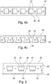
- Figures 4a to 4c show examples of perforated strips 42 and a comb 44.
- Fig. 4a shows a perforated strip 42 comprising trapezoidal perforations.
- the perforations may be provided to the strip 42 by stamping, i.e. trapezoidal-shaped parts may be stamped out of the strip. Alternatively, the parts may be produced by laser cutting, water jet cutting or electron beam cutting.
- the perforations define the position of the plurality of channels 26.
- the material of the strip 42 between the perforations forms the plurality of channel sidewalls 24.
- the plurality of channel sidewalls 24 may further be provided with openings 40 for feeding through fastening elements.
- Fig. 4b shows a perforated strip 42 comprising a plurality of channel sidewalls 24 being parallel to each other.
- Fig. 4c shows a comb 44.
- the teeth of the comb 44 provide the plurality of channel sidewalls 24.
- the shape of the teeth defines the shape of the plurality of channel sidewalls 24.
- the space between the teeth define the location of the plurality of channels 26.
- the perforated strip 42 or the comb 44 may be arranged between the portion 30 and the top skin 18, wherein fig. 5 does not show the top skin 18 for the sake of an unobstructed view.
- the perforations bridge the portion 30 such that the perforations are in fluid communication with the front bay 20 and the aft bay 22.
- a portion 46 of the perforated strip 42 being arranged in the aft bay 22 may be removed to remove a possible obstacle of the airflow flowing out of the plurality of channels 26 into the aft bay 22.
- the removal of the portion 46 may not be required if the perforated strip 42 is thin in the direction between the portion 30 of the strap 18 and the top skin 16 such that the airflow is not obstructed by the portion 46.
- a portion 48 of the perforated strip 42 being arranged in the front bay 20 may also be removed. This also applies to the comb 44. This may also improve the airflow through the plurality of channels 26 since the portion 48 may provide an obstacle for the entry of the air into the plurality of channels 26. Thus, the entry of the air into the plurality of channels 26 may be simplified by the removal. Also, in this case, the removal may not be required if the perforated strip 42 or the comb 44 are thin in direction between the portion 30 of the strap and the top skin 16.
- Fig. 6a and 6b show an alternative exemplary embodiment of the invention.
- the portion 48 of the perforated strip 42 being arranged between the spar 18 and the top skin 16 is bend away from the top skin 16 towards the spar 18.
- the portion 48 therefore forms a flange 50 which is connected to the plurality of channel sidewalls 24.
- the flange 50 may be connected to the spar 18 by fastening elements 38.
- the presence of the flange 50 has the effect that the perforated strip 42 is angled which improves the area moment of inertia of the perforated strip 42.
- this embodiment comprises an increased stability.
- the perforated strip 42 according to fig. 6a is bend after mounting the perforated strip 42 between the strap 18 and the top skin 16.
- Fig. 6b shows a perforated strip 42 which is a bend before the installation on the strap 18.
- portion 46 of the perforated strip 42 may be bend towards the strap 18 to provide a flange (not shown). This will have analogous effects to as the bending of portion 48.
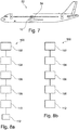
- Fig. 7 shows an aircraft as an example of an aerospace vehicle 52 comprising a wing 54 with a leading-edge.
- the vented leading-edge assembly 10 may be arranged at the leading-edge of the wing 54.
- the vented leading-edge assembly 10 provides the slat 12 for the wing 54.
- Figs. 8a and 8b show different exemplary embodiments of a method 100 for manufacturing a vented leading-edge assembly according to the above description.
- a slat comprising a bay and a top skin is provided.
- the top skin delimits a portion of the bay.
- a spar is arranged in the bay of the slat.
- the spar divides the bay into a front bay and an aft bay.
- a strip comprising a row of a plurality of perforations.
- the strip is therefore a perforated strip.
- the material between the perforations define a plurality of channel sidewalls.
- a comb comprising a plurality of teeth may be provided wherein those teeth define a plurality of channel sidewalls.
- the strip is connected between the spar and the top skin.
- the connection is performed such that the perforations bridge the spar, i.e. providing fluid communication between the front bay to the aft bay.
- a portion between the front bay and the aft bay provides a channel which is arranged between the spar and the top skin.
- a portion of the spar defines a lower channel wall for those channels.
- the method may comprise step 110 in which at least one portion of the strip being arranged between the row of perforations and the aft bay is removed.
- step 112 may be provided in which at least one portion of the strip being arranged between the row of perforations in the front bay may be removed.
- the removal of the portions may improve the airflow from the front bay through the plurality of channels to the aft bay along the top skin.
- step 110 may be left out and only step 112 may be performed.
Landscapes
- Engineering & Computer Science (AREA)
- Aviation & Aerospace Engineering (AREA)
- Mechanical Engineering (AREA)
- Structures Of Non-Positive Displacement Pumps (AREA)
- Turbine Rotor Nozzle Sealing (AREA)
Abstract
Description
- The invention relates to a vented leading-edge assembly, the assembly comprising: a slat comprising a bay and a top skin delimiting a portion of the bay; a spar being arranged in the slat, the spar dividing the bay in a front bay and an aft bay; and a plurality of channel sidewalls being arranged between the top skin and the spar, the plurality of channel sidewalls defining a plurality of channels between the front bay and the aft bay and a method for manufacturing a vented leading-edge assembly.
- Aircrafts flying in great heights may be subject to icing of the wings. Typically, the ice may form on the leading-edge of the wing. The leading-edge of the wing may comprise a slat. A common approach to prevent icing is to heat up the concerned parts with bleed air from the engines. This is not trivial since the slat body usually comprises a spar which separates the interior structure of the slat into two chambers. Furthermore, the bleed air streams out of the tube which is arranged in a front chamber of the slat. To lead the bleed air between the two chambers in the slat it is known to provide a special part between the upper part of the spar and the top skin of the slat. That special part comprises channels which allow the bleed air to travel from one chamber to another. The aft chamber of the slat may further comprise an air outlet to the outside of the slat to compensate the pressure which is increased by the inflowing bleed air.
- According to
CN 2014 72669 U the upper skin of the slat comprises grooves on its inner side. The grooves are covered by an inner skin which is arranged between the spar and the inner side of the top skin of the slat. - The manufacturing of the grooves or the special part requires complex milling which may lead to a long and expensive production cycle.
- Thus, there is the need for providing an improved leading-edge assembly and an improved method of manufacturing a leading-edge assembly.
- The object is solved by the features of the independent claims. Advantageous embodiments are subject matter of the dependent claims and the following description.
- According to the invention, a vented leading-edge assembly is provided, the assembly comprising: a slat comprising a bay and a top skin delimiting a portion of the bay; a spar being arranged in the slat, the spar dividing the bay in a front bay and an aft bay; and a plurality of channel sidewalls being arranged between the top skin and the spar, the plurality of channel sidewalls defining a plurality of channels between the front bay and the aft bay, wherein at least a portion of the spar defines lower channel walls for the plurality of channels.
- The invention therefore provides channels which are defined by the channel sidewalls and the spar as lower channel wall for each channel. Furthermore, the top skin of the slat may provide an upper channel wall for the channels. The channel sidewalls are separate elements from the top skin of the slat and from the spar. Consequently, milling procedures on the slat or on the spar to provide sidewalls which are integral to the slat or the spar are avoided. Furthermore, since at least a portion of the spar defines a lower channel wall for each of the plurality of the channels, for manufacturing the channels the channel sidewalls may just be placed on the portion of spar between the spar and the top skin of the slat. This simplifies and accelerates the production of the vented leading-edge assembly. This allows a high rate production of the vented leading-edge assembly. Furthermore, since milling is avoided, the production of the vented leading-edge is simple and cost-effective.
- In an example, the plurality of channel sidewalls is non-parallel to each other such that a distance between the plurality of channel sidewalls at the front bay is bigger than a distance between the plurality of channel sidewalls at the aft bay.
- Due to the different distances between the channel sidewalls and non-parallel channel sidewalls the cross section of the channel reduces from the front bay to the aft bay. A flow of bleed air starting in the front bay will be accelerated when passing the channels in direction of the aft bay. Due to the acceleration of the bleed air flow, the flow keeps its flow direction after exiting the channel which leads the bleed air flow along the total length of the top skin. This avoids a stop or a dissipation of the bleed air flow before reaching the end of the top skin of the slat being distal to the leading-edge of the slat. Consequently, the complete top skin of the slat may be heated by the bleed air.
- In another example, the plurality of channel sidewalls is parallel.
- In this example, the channels being formed by the channel sidewalls do not accelerate the bleed air flow. Such channels may be provided if the pressure of the bleed air flow is sufficient to flow along the entire length of the top skin.
- In a further example, the leading-edge assembly comprises a plurality of fastening elements connecting the top skin to the spar through the plurality of channel sidewalls.
- That kind of connection of the plurality of channel sidewalls to the top skin and to the spar is simple and cost effective.
- Furthermore, in an example, the plurality of channel sidewalls is provided by a perforated strip being arranged between the top skin and the spar. The perforated strip may comprise a single row of perforations along the length of the strip.
- Such a perforated strip can be easily produced by stamping the row of perforations into the strip. Alternatively, the strip may be laser cut, water jet cut, electron beam cut or further cutting methods. The material between the perforations on the strip defines the channel sidewalls. The stamping may further define the shape of the perforations and thus the angle between the channel sidewalls. When mounting the perforated strip on the spar, the row of perforations may be arranged such that they bridge the complete portion of the spar which defines the lower channel wall of the plurality of channels. Furthermore, they may be mounted such that they are in fluid communication with the front bay and the aft bay. Thus, by just mounting the perforated strip between the spar and the top skin of the slat, all of the plurality of channel sidewalls may be provided at once.
- In another example, the plurality of channel sidewalls is provided by a comb being arranged between the top skin and the spar.
- In this example, the teeth of the comb define the channel sidewalls. The comb may for example be manufactured by stamping, laser cutting, water jet cutting or electron beam cutting. Alternatively, one portion of a perforated strip may be removed, wherein the portion is in contact with the row of perforations. Both alternatives provide a simple way to mount the channel sidewalls between the spar and the top skin of the slat. Furthermore, the comb provides channels which, at least at one end, do not have any material obstructing the airflow.
- In an example, the channel sidewalls comprise a common flange protruding from the plurality of channel sidewalls and extending along the spar, wherein preferably fixation elements connect the flange to the spar.
- The flange provides an increased stability for the fixation of the channel sidewalls to the spar. This further increases the area moment of inertia of a structure. Thus, the stability of the vented leading-edge assembly is improved.
- Moreover, in another example, the front bay comprises a de-icing air outlet being configured to fill the front bay with de-icing air.
- In that example, the de-icing air outlet may be a bleeding air outlet being in fluid communication with an engine of an aircraft.
- According to the invention, also an aerospace vehicle is provided, the aerospace vehicle comprising: a wing; and a vented leading-edge assembly according to the above description; wherein the vented leading-edge assembly is arranged on a leading-edge of the wing.
- The effects and further embodiments of an aerospace vehicle according to the present invention are analogous to the effects and embodiments of the description mentioned above. Thus, it is referred to the above description of the vented leading-edge assembly.
- According to the invention, also a method for manufacturing a vented leading-edge assembly is provided, the method comprising the following steps: providing a slat comprising a bay and a top skin delimiting a portion of the bay; arranging a spar in the bay such that the spar divides the bay into a front bay and an aft bay; providing a strip comprising a row of a plurality of perforations; and connecting the strip between the spar and the top skin such that each perforation is in fluid communication with the front bay and the aft bay forming a channel between the front bay and the aft bay.
- The effects and further embodiments of a method according to the present invention are analogous to the effects and embodiments of the description mentioned above. Thus, it is referred to the above description of the vented leading-edge assembly.
- In an example, the method further comprises at least one of the following steps: removing at least one portion of the strip being arranged between the row and the aft bay; removing at least one portion of the strip being arranged between the row and the front bay.
- This may remove obstacles in the path of the streaming air and further reduces the weight of the leading-edge assembly.
- In the following the invention is described by the means of an exemplary embodiment using the attached drawing.
- Fig. 1
- shows a schematic drawing of a vented leading-edge assembly.
- Fig. 2
- shows a schematic longitudinal cross section of
figure 1 with an indicated airflow. - Figs. 3a, b
- show a schematic drawings of different view angles on the channel sidewalls.
- Figs. 4a-c
- show different schematic examples perforated strips and combs.
- Fig. 5
- shows a schematic drawing of a top view on a mounted perforated strip.
- Figs. 6a, b
- show schematic drawings of channel sidewalls with a flange.
- Fig. 7
- shows a schematic drawing of an aerospace vehicle.
- Figs. 8a, b
- show flow charts of different embodiments of the method.
-
Fig. 1 shows a schematic drawing of a vented leading-edge assembly which in its entirety is denoted withreference sign 10. - The vented leading-
edge assembly 10 comprises aslat 12 having atop skin 16 and arear skin 35. Thetop skin 16 and therear skin 35 delimit portions of abay 14 which forms a chamber inside theslat 12. Therear skin 35 comprisesopenings 36 which provide a fluid communication between thebay 14 and the space outside of theslat 12. - The vented leading-
edge assembly 10 further comprises aspar 18. Thespar 18 is arranged in thebay 14 of theslat 12. Thespar 18 comprises aportion 30 which is arranged parallel to thetop skin 16. Furthermore, thespar 18 divides thebay 14 into afront bay 20 and anaft bay 22. Thefront bay 20 is arranged closer to the leading-edge of theslat 12 than theaft bay 22. - To de-ice the
slat 12, the vented leading-edge assembly 10 may for example comprise ade-icing air outlet 32 which may be arranged in thefront bay 20. Thede-icing air outlet 32 may be a pipe which is in fluid communication with an engine of an aerospace vehicle. The engine provides bleeding air to the pipe. Thede-icing air outlet 32 may then compriseoutlet openings 34 which allow the bleed air to be introduced into thefront bay 20. - The vented leading-
edge assembly 10 further comprises a plurality of channel sidewalls 24 being provided between theportion 30 of thespar 18 and thetop skin 16. For example, the channel sidewalls 24 may be sheets, plates or portions thereof. In combination with theportion 30 and thetop skin 16, the plurality of channel sidewalls 24 provide a plurality ofchannels 26 being arranged between thetop skin 16 and thespar 18. Theportion 30 of thespar 18 then forms alower channel wall 28 for each of the plurality of thechannels 26. Those plurality ofchannels 26 provide fluid communication between thefront bay 20 and theaft bay 22. - Fastening
elements 38 may be provided to fix thespar 18 to thetop skin 16. Thosefastening elements 38 may be rivets or screws or the like. Thefastening elements 38 connect thetop skin 16 through the plurality of channel sidewalls 24 to theportion 30 of thespar 18. - An example of an airflow of de-icing air is indicated in
fig. 2 . The de-icing air which may be bleed air from an aircraft engine exits from thede-icing air outlet 32 and flows along the walls of thefront bay 20. This means, that the skin of theslat 12 at thefront bay 20 is heated by the de-icing air. The de-icing air flows along thetop skin 16 towards thespar 18. At thespar 18, the de-icing air flows through the plurality ofchannels 26 from thefront bay 20 to theaft bay 22. The flow of the de-icing air continues along thetop skin 16 in theaft bay 22. The inflowing de-icing air increases the pressure in theaft bay 22. This increased pressure leads to a flow towards and through theopenings 36 in therear skin 35. Theopenings 36 vent theaft bay 22 to the outside air. - A more detailed view of the plurality of
channels 26 is shown infigures 3a and 3b. Fig. 3a provides a view through the plurality ofchannels 26. Thetop skin 16, the plurality ofchannel sidewalls 24 and theportion 30 of thespar 18 are shown in a cross-sectional view. Thefastening elements 38 are arranged at the positions of the plurality of channel sidewalls 24 to connect thetop skin 16 to the portion 13. Thefastening elements 38 travel through the plurality of channel sidewalls 24 in a one-to-one manner. However, also more than onefastening element 38 perchannel sidewall 24 may be provided. -
Fig. 3b provides a top view on the mounted plurality ofchannel sidewalls 24. This view may also be understood as a view from the inner side of thetop skin 16 down to thespar 18. The plurality ofchannel sidewalls 24 are arranged on theportion 30 of thespar 18. This view shows that theportion 30 provides thelower channel walls 28 for the plurality ofchannels 26 between the plurality ofchannel sidewalls 24. Furthermore, theopenings 40 in the plurality of channel sidewalls 24 denote the position of thefastening elements 38 which connect thetop skin 16 to thespar 18 by being arranged through the plurality ofchannel sidewalls 24. - In
fig. 3b , the plurality ofchannel sidewalls 24 are angled to each other. The distance between the channel sidewalls 24 at thefront bay 20 is larger than the distance between the channel sidewalls 24 at theaft bay 22. This leads to a diminishing cross-section for the plurality ofchannels 26 from thefront bay 20 to theaft bay 22. Therefore, an airflow flowing through the plurality ofchannels 26 from thefront bay 20 to theaft bay 22 will be accelerated due to the diminishing cross-section. The acceleration of the airflow ensures that the airflow along thetop skin 16 in theaft bay 22 reaches the end of thetop skin 16, i.e. flows along the whole length of thetop skin 16. - The angle between the channel sidewalls 24 of the
single channel 26 determines the amount of acceleration of an airflow streaming through thechannel 26. Thus, the acceleration of the airflow may be adjusted by choosing the angle between the plurality of channel sidewalls 24 of the plurality ofchannels 26. It is also possible, to provide a plurality ofparallel channel sidewalls 24, i.e. no acceleration is provided to the airflow through the plurality ofchannels 26. - For arranging the plurality of channel sidewalls 24 to the
portion 30 of thespar 18, the plurality ofchannel sidewalls 24 may be provided on aperforated strip 42 or acomb 44.Figures 4a to 4c show examples ofperforated strips 42 and acomb 44. -
Fig. 4a shows aperforated strip 42 comprising trapezoidal perforations. The perforations may be provided to thestrip 42 by stamping, i.e. trapezoidal-shaped parts may be stamped out of the strip. Alternatively, the parts may be produced by laser cutting, water jet cutting or electron beam cutting. The perforations define the position of the plurality ofchannels 26. The material of thestrip 42 between the perforations forms the plurality ofchannel sidewalls 24. The plurality ofchannel sidewalls 24 may further be provided withopenings 40 for feeding through fastening elements. -
Fig. 4b shows aperforated strip 42 comprising a plurality of channel sidewalls 24 being parallel to each other. -
Fig. 4c shows acomb 44. The teeth of thecomb 44 provide the plurality ofchannel sidewalls 24. The shape of the teeth defines the shape of the plurality ofchannel sidewalls 24. The space between the teeth define the location of the plurality ofchannels 26. - According to
figure 5 , theperforated strip 42 or thecomb 44 may be arranged between theportion 30 and thetop skin 18, whereinfig. 5 does not show thetop skin 18 for the sake of an unobstructed view. The perforations bridge theportion 30 such that the perforations are in fluid communication with thefront bay 20 and theaft bay 22. - A
portion 46 of theperforated strip 42 being arranged in theaft bay 22 may be removed to remove a possible obstacle of the airflow flowing out of the plurality ofchannels 26 into theaft bay 22. However, the removal of theportion 46 may not be required if theperforated strip 42 is thin in the direction between theportion 30 of thestrap 18 and thetop skin 16 such that the airflow is not obstructed by theportion 46. - Furthermore, a
portion 48 of theperforated strip 42 being arranged in thefront bay 20 may also be removed. This also applies to thecomb 44. This may also improve the airflow through the plurality ofchannels 26 since theportion 48 may provide an obstacle for the entry of the air into the plurality ofchannels 26. Thus, the entry of the air into the plurality ofchannels 26 may be simplified by the removal. Also, in this case, the removal may not be required if theperforated strip 42 or thecomb 44 are thin in direction between theportion 30 of the strap and thetop skin 16. -
Fig. 6a and 6b show an alternative exemplary embodiment of the invention. In this embodiment, as shown infig. 6a , theportion 48 of theperforated strip 42 being arranged between thespar 18 and thetop skin 16 is bend away from thetop skin 16 towards thespar 18. Theportion 48 therefore forms aflange 50 which is connected to the plurality ofchannel sidewalls 24. Furthermore, theflange 50 may be connected to thespar 18 byfastening elements 38. The presence of theflange 50 has the effect that theperforated strip 42 is angled which improves the area moment of inertia of theperforated strip 42. Thus, this embodiment comprises an increased stability. - The
perforated strip 42 according tofig. 6a is bend after mounting theperforated strip 42 between thestrap 18 and thetop skin 16. -
Fig. 6b shows aperforated strip 42 which is a bend before the installation on thestrap 18. - The skilled person understands that also the
portion 46 of theperforated strip 42 may be bend towards thestrap 18 to provide a flange (not shown). This will have analogous effects to as the bending ofportion 48. -
Fig. 7 shows an aircraft as an example of anaerospace vehicle 52 comprising awing 54 with a leading-edge. The vented leading-edge assembly 10 may be arranged at the leading-edge of thewing 54. Thus, the vented leading-edge assembly 10 provides theslat 12 for thewing 54. -
Figs. 8a and 8b show different exemplary embodiments of amethod 100 for manufacturing a vented leading-edge assembly according to the above description. - In
step 102, a slat comprising a bay and a top skin is provided. The top skin delimits a portion of the bay. - In
step 104, a spar is arranged in the bay of the slat. The spar divides the bay into a front bay and an aft bay. - According to step 106, a strip comprising a row of a plurality of perforations is provided. The strip is therefore a perforated strip. The material between the perforations define a plurality of channel sidewalls. Alternatively, also a comb comprising a plurality of teeth may be provided wherein those teeth define a plurality of channel sidewalls.
- According to step 108, the strip is connected between the spar and the top skin. The connection is performed such that the perforations bridge the spar, i.e. providing fluid communication between the front bay to the aft bay. This means, that one portion of the perforations opens to the front bay and another portion of the perforations opens to the aft bay. A portion between the front bay and the aft bay provides a channel which is arranged between the spar and the top skin. Furthermore, this means, that a portion of the spar defines a lower channel wall for those channels.
- According to
fig. 8a , the method may comprisestep 110 in which at least one portion of the strip being arranged between the row of perforations and the aft bay is removed. Optionally, also step 112 may be provided in which at least one portion of the strip being arranged between the row of perforations in the front bay may be removed. - The removal of the portions may improve the airflow from the front bay through the plurality of channels to the aft bay along the top skin.
- According to
fig. 8b ,step 110 may be left out and only step 112 may be performed.
Claims (12)
- Vented leading-edge assembly, the assembly (10) comprising:a slat (12) comprising a bay (14) and a top skin (16) delimiting a portion of the bay (14);a spar (18) being arranged in the slat (12), the spar (18) dividing the bay (14) in a front bay (20) and an aft bay (22); anda plurality of channel sidewalls (24) being arranged between the top skin (16) and the spar (18), the plurality of channel sidewalls (24) defining a plurality of channels (26) between the front bay (20) and the aft bay (22),wherein at least a portion (30) of the spar (18) defines lower channel walls (28) for the plurality of channels (26).
- Vented leading-edge assembly according to claim 1, wherein the plurality of channel sidewalls (24) are non-parallel to each other such that a distance between the plurality of channel sidewalls (24) at the front bay (20) is bigger than a distance between the plurality of channel sidewalls (24) at the aft bay (22).
- Vented leading-edge assembly according to claim 1, wherein the plurality of channel sidewalls (24) are parallel.
- Vented leading-edge assembly according to one of claims 1 to 3, wherein the leading-edge assembly (10) comprises a plurality of fastening elements (38) connecting the top skin (16) to the spar (18) through the plurality of channel sidewalls (24).
- Vented leading-edge assembly according to one of claims 1 to 4, wherein the plurality of channel sidewalls (24) is provided by a perforated strip (42) being arranged between the top skin (16) and the spar (18).
- Vented leading-edge assembly according to one of claims 1 to 4, wherein the plurality of channel sidewalls (24) is provided by a comb (44) being arranged between the top skin (16) and the spar (18).
- Vented leading-edge assembly according to claim 5 or 6, wherein the channel sidewalls (24) comprise a common flange (50) protruding along the spar (18), wherein preferably fastening elements (38) connect the flange (50) to the spar (18).
- Vented leading-edge assembly according to one of claims 1 to 7, wherein the front bay (20) comprises a de-icing air outlet (32) being configured to fill the front bay (20) with de-icing air.
- Vented leading-edge assembly according to claim 8, wherein the de-icing air outlet (32) is a bleeding air outlet being in fluid communication with an engine of an aerospace vehicle.
- Aerospace vehicle (52) comprising
a wing (54); and
a vented leading-edge assembly (10) according to one of claims 1 to 9;
wherein the vented leading-edge assembly (10) is arranged on a leading-edge of the wing (54). - Method for manufacturing a vented leading-edge assembly, the method (100) comprising the following steps:- Providing (102) a slat comprising a bay and a top skin delimiting a portion of the bay;- Arranging (104) a spar in the bay such that the spar divides the bay into a front bay and an aft bay;- Providing (106) a strip comprising a row of a plurality of perforations; and- Connecting (108) the strip between the spar and the top skin such that each perforation is in fluid communication with the front bay and the aft bay forming a channel between the front bay and the aft bay.
- Method according to claim 11, wherein the method further comprises at least one of the following steps:- Removing (110) at least one portion of the strip being arranged between the row and the aft bay;- Removing (112) at least one portion of the strip being arranged between the row and the front bay.
Applications Claiming Priority (1)
| Application Number | Priority Date | Filing Date | Title |
|---|---|---|---|
| DE102018126305 | 2018-10-23 |
Publications (2)
| Publication Number | Publication Date |
|---|---|
| EP3643616A1 true EP3643616A1 (en) | 2020-04-29 |
| EP3643616B1 EP3643616B1 (en) | 2021-12-08 |
Family
ID=68281020
Family Applications (1)
| Application Number | Title | Priority Date | Filing Date |
|---|---|---|---|
| EP19203214.2A Active EP3643616B1 (en) | 2018-10-23 | 2019-10-15 | Vented leading-edge assembly and method for manufacturing a vented leading-edge assembly |
Country Status (3)
| Country | Link |
|---|---|
| US (1) | US11440665B2 (en) |
| EP (1) | EP3643616B1 (en) |
| CN (1) | CN111086627A (en) |
Cited By (1)
| Publication number | Priority date | Publication date | Assignee | Title |
|---|---|---|---|---|
| EP3733504A1 (en) * | 2019-04-30 | 2020-11-04 | Airbus Operations GmbH | Leading-edge device for an aircraft |
Families Citing this family (4)
| Publication number | Priority date | Publication date | Assignee | Title |
|---|---|---|---|---|
| US20220111951A1 (en) * | 2020-10-08 | 2022-04-14 | The Boeing Company | Air acceleration at leading edge of wing |
| EP4074602A1 (en) * | 2021-04-13 | 2022-10-19 | Airbus Operations GmbH | Piccolo tube for de-icing an airfoil structure of an aircraft, de-icing system and airfoil structure |
| CN113844659B (en) * | 2021-09-30 | 2023-06-23 | 中航通飞华南飞机工业有限公司 | Aircraft double-skin anti-icing cavity structure and heat exchange method |
| CN114872901A (en) * | 2022-04-08 | 2022-08-09 | 中国商用飞机有限责任公司 | fixed leading edge |
Citations (6)
| Publication number | Priority date | Publication date | Assignee | Title |
|---|---|---|---|---|
| US3933327A (en) * | 1974-08-30 | 1976-01-20 | Rohr Industries, Inc. | Aircraft anti-icing plenum |
| WO2000064737A1 (en) * | 1999-04-23 | 2000-11-02 | Rosemount Aerospace Inc. | Acoustic reflector attachment compatible with native aircraft structure |
| DE60102840T2 (en) * | 2000-01-17 | 2005-04-28 | Dassault Aviation | Vane deicing device for a wing of an aircraft |
| CN201472669U (en) | 2009-06-04 | 2010-05-19 | 中国航空工业集团公司西安飞机设计研究所 | Aircraft leading edge slat anti-icing hot air channel |
| CN205440885U (en) * | 2015-12-17 | 2016-08-10 | 中国商用飞机有限责任公司 | Slat leading edge anti-icing cavity |
| US20180170557A1 (en) * | 2016-12-20 | 2018-06-21 | Airbus Operations Gmbh | Leading edge ice-protection system |
Family Cites Families (26)
| Publication number | Priority date | Publication date | Assignee | Title |
|---|---|---|---|---|
| US1797160A (en) * | 1931-03-17 | Aeroplane | ||
| US4752049A (en) | 1985-12-30 | 1988-06-21 | The Boeing Company | Leading edge slat/anti-icing system and method for airfoil |
| US4738416A (en) * | 1986-09-26 | 1988-04-19 | Quiet Nacelle Corporation | Nacelle anti-icing system |
| USH648H (en) * | 1988-08-12 | 1989-07-04 | The United States Of America As Represented By The Secretary Of The Air Force | Air passage device |
| EP0746802A4 (en) | 1993-11-26 | 1997-10-15 | Voxel | APPARATUS FOR RECONSTRUCTION OF HOLOGRAPHIC IMAGES |
| RU2127202C1 (en) | 1998-04-16 | 1999-03-10 | Назаров Валентин Васильевич | Method of creating system of forces of aircraft of aeroplane configuration and ground-air amphibious vehicle for implementing this method |
| DE10019185C2 (en) * | 2000-04-17 | 2003-06-05 | Airbus Gmbh | Arrangement for aerodynamic noise reduction of slats in a commercial aircraft |
| FR2820716B1 (en) * | 2001-02-15 | 2003-05-30 | Eads Airbus Sa | PROCESS FOR DEFROSTING BY FORCED CIRCULATION OF A FLUID, OF A REACTION ENGINE AIR INLET COVER AND DEVICE FOR ITS IMPLEMENTATION |
| EP1379554A2 (en) | 2001-02-21 | 2004-01-14 | Curagen Corporation | Proteins, polynucleotides encoding them and methods of using the same |
| US6965816B2 (en) | 2001-10-01 | 2005-11-15 | Kline & Walker, Llc | PFN/TRAC system FAA upgrades for accountable remote and robotics control to stop the unauthorized use of aircraft and to improve equipment management and public safety in transportation |
| US7210653B2 (en) | 2002-10-22 | 2007-05-01 | The Boeing Company | Electric-based secondary power system architectures for aircraft |
| GB2417937B (en) | 2004-09-10 | 2009-08-12 | Ultra Electronics Ltd | An aircraft wing coupling arrangement |
| CA2640926A1 (en) | 2005-12-12 | 2007-06-21 | Carrier Corporation | Beverage dispenser with on-demand refrigeration |
| US8387362B2 (en) * | 2006-10-19 | 2013-03-05 | Michael Ralph Storage | Method and apparatus for operating gas turbine engine heat exchangers |
| GB2447228B8 (en) * | 2007-03-06 | 2009-03-04 | Gkn Aerospace Services Ltd | Thermal anti-icing system |
| FR2924409B1 (en) * | 2007-12-03 | 2010-05-14 | Airbus France | AIRCRAFT NACELLE COMPRISING MEANS FOR HOT AIR EXHAUST |
| WO2014142937A1 (en) | 2013-03-15 | 2014-09-18 | Hallco Industries Inc. | Bearingless reciprocating slat-type conveyor assemblies |
| GB2470043B (en) | 2009-05-06 | 2011-06-08 | Gkn Aerospace Services Ltd | Heating system |
| WO2015198093A1 (en) | 2014-06-24 | 2015-12-30 | Peter Ireland | Efficiency improvements for flow control body and system shocks |
| GB201011378D0 (en) | 2010-07-06 | 2010-08-18 | Ultra Electronics Ltd | Linkage for guiding a flexible cable |
| US9490414B2 (en) | 2011-08-31 | 2016-11-08 | L. Pierre de Rochemont | Fully integrated thermoelectric devices and their application to aerospace de-icing systems |
| US9896190B1 (en) * | 2014-05-07 | 2018-02-20 | The Boeing Company | Wing leading edge architecture suitable for laminar flow |
| US9950799B2 (en) | 2016-03-09 | 2018-04-24 | Honeywell International Inc. | Shielded anti-icing system and methods |
| EP3478572B1 (en) | 2016-06-29 | 2020-11-11 | Bombardier Inc. | Temperature monitoring unit for aircraft wing structure and associated installation method |
| US12017771B2 (en) * | 2017-10-12 | 2024-06-25 | United States Of America As Represented By The Administrator Of Nasa | Slat-cove filler for wing structure of an aircraft |
| DE102019111135A1 (en) * | 2019-04-30 | 2020-11-05 | Airbus Operations Gmbh | Leading edge device for an aircraft |
-
2019
- 2019-10-08 US US16/595,722 patent/US11440665B2/en active Active
- 2019-10-15 EP EP19203214.2A patent/EP3643616B1/en active Active
- 2019-10-23 CN CN201911011600.7A patent/CN111086627A/en active Pending
Patent Citations (6)
| Publication number | Priority date | Publication date | Assignee | Title |
|---|---|---|---|---|
| US3933327A (en) * | 1974-08-30 | 1976-01-20 | Rohr Industries, Inc. | Aircraft anti-icing plenum |
| WO2000064737A1 (en) * | 1999-04-23 | 2000-11-02 | Rosemount Aerospace Inc. | Acoustic reflector attachment compatible with native aircraft structure |
| DE60102840T2 (en) * | 2000-01-17 | 2005-04-28 | Dassault Aviation | Vane deicing device for a wing of an aircraft |
| CN201472669U (en) | 2009-06-04 | 2010-05-19 | 中国航空工业集团公司西安飞机设计研究所 | Aircraft leading edge slat anti-icing hot air channel |
| CN205440885U (en) * | 2015-12-17 | 2016-08-10 | 中国商用飞机有限责任公司 | Slat leading edge anti-icing cavity |
| US20180170557A1 (en) * | 2016-12-20 | 2018-06-21 | Airbus Operations Gmbh | Leading edge ice-protection system |
Cited By (1)
| Publication number | Priority date | Publication date | Assignee | Title |
|---|---|---|---|---|
| EP3733504A1 (en) * | 2019-04-30 | 2020-11-04 | Airbus Operations GmbH | Leading-edge device for an aircraft |
Also Published As
| Publication number | Publication date |
|---|---|
| US11440665B2 (en) | 2022-09-13 |
| CN111086627A (en) | 2020-05-01 |
| US20200148368A1 (en) | 2020-05-14 |
| EP3643616B1 (en) | 2021-12-08 |
Similar Documents
| Publication | Publication Date | Title |
|---|---|---|
| EP3643616B1 (en) | Vented leading-edge assembly and method for manufacturing a vented leading-edge assembly | |
| EP3733504B1 (en) | Leading-edge device for an aircraft | |
| EP2873617B1 (en) | Device and method for de-icing and/or avoiding ice-buildup and profiled body and aircraft equipped with such a device | |
| EP2955108B1 (en) | Leading edge nose structure on the vertical stabilizer of an aircraft | |
| CA2865853C (en) | Aircraft anti-icing systems having deflector vanes | |
| JP5830086B2 (en) | Aircraft high lift device | |
| US7815498B2 (en) | Device for distribution of air within the passenger compartment of a vehicle | |
| EP2129579B1 (en) | Air intake duct with thermal anti-icing system | |
| EP2644497A1 (en) | Wing for an aircraft, aircraft and method for reducing aerodynamic drag and improving maximum lift | |
| EP3199450B1 (en) | Flow body for an aircraft for passive boundary layer suction | |
| CN208559575U (en) | Vehicle Pneumatic Components and Vehicles | |
| JP5710005B2 (en) | Slat, aircraft wing, aircraft rotor blade, aircraft | |
| CA2889085A1 (en) | An aircraft with a framework structure that comprises at least one hollow frame | |
| EP3205582B1 (en) | Total air temperature probe with efficient particle pass through | |
| US6116365A (en) | Arrangement for ventilating an assembly on a vehicle | |
| US20090270022A1 (en) | Climate control duct architecture for a vehicle | |
| EP0052242A1 (en) | Device for influencing the current at aerodynamic structures | |
| WO2011099276A1 (en) | High lift generator, wing, and slat | |
| EP3020638B1 (en) | Device and method for de-icing and/or avoiding ice-buildup and profiled body and aircraft equipped with such a device | |
| US11208202B2 (en) | Flow body of an aircraft and aircraft | |
| US11873095B2 (en) | Leading-edge component for an aircraft | |
| BR102015025991A2 (en) | AIRCRAFT, WING ROOT CAPITAL ASSEMBLY FOR AN AIRCRAFT AND AIR EXCHANGE SYSTEM FOR A AIRCRAFT WING ROOT CAVING | |
| US11873107B2 (en) | Piccolo tube for de-icing an airfoil structure of an aircraft, de-icing system and airfoil structure | |
| US12351319B2 (en) | Heated leading-edge structure for an aircraft | |
| JP6516450B2 (en) | aircraft |
Legal Events
| Date | Code | Title | Description |
|---|---|---|---|
| PUAI | Public reference made under article 153(3) epc to a published international application that has entered the european phase |
Free format text: ORIGINAL CODE: 0009012 |
|
| STAA | Information on the status of an ep patent application or granted ep patent |
Free format text: STATUS: THE APPLICATION HAS BEEN PUBLISHED |
|
| AK | Designated contracting states |
Kind code of ref document: A1 Designated state(s): AL AT BE BG CH CY CZ DE DK EE ES FI FR GB GR HR HU IE IS IT LI LT LU LV MC MK MT NL NO PL PT RO RS SE SI SK SM TR |
|
| AX | Request for extension of the european patent |
Extension state: BA ME |
|
| STAA | Information on the status of an ep patent application or granted ep patent |
Free format text: STATUS: REQUEST FOR EXAMINATION WAS MADE |
|
| 17P | Request for examination filed |
Effective date: 20201029 |
|
| RBV | Designated contracting states (corrected) |
Designated state(s): AL AT BE BG CH CY CZ DE DK EE ES FI FR GB GR HR HU IE IS IT LI LT LU LV MC MK MT NL NO PL PT RO RS SE SI SK SM TR |
|
| STAA | Information on the status of an ep patent application or granted ep patent |
Free format text: STATUS: EXAMINATION IS IN PROGRESS |
|
| 17Q | First examination report despatched |
Effective date: 20210205 |
|
| GRAP | Despatch of communication of intention to grant a patent |
Free format text: ORIGINAL CODE: EPIDOSNIGR1 |
|
| STAA | Information on the status of an ep patent application or granted ep patent |
Free format text: STATUS: GRANT OF PATENT IS INTENDED |
|
| RIC1 | Information provided on ipc code assigned before grant |
Ipc: B64C 9/24 20060101ALN20210922BHEP Ipc: B64C 9/22 20060101ALI20210922BHEP Ipc: B64D 15/04 20060101AFI20210922BHEP |
|
| GRAS | Grant fee paid |
Free format text: ORIGINAL CODE: EPIDOSNIGR3 |
|
| GRAA | (expected) grant |
Free format text: ORIGINAL CODE: 0009210 |
|
| STAA | Information on the status of an ep patent application or granted ep patent |
Free format text: STATUS: THE PATENT HAS BEEN GRANTED |
|
| INTG | Intention to grant announced |
Effective date: 20211014 |
|
| AK | Designated contracting states |
Kind code of ref document: B1 Designated state(s): AL AT BE BG CH CY CZ DE DK EE ES FI FR GB GR HR HU IE IS IT LI LT LU LV MC MK MT NL NO PL PT RO RS SE SI SK SM TR |
|
| REG | Reference to a national code |
Ref country code: GB Ref legal event code: FG4D |
|
| REG | Reference to a national code |
Ref country code: AT Ref legal event code: REF Ref document number: 1453601 Country of ref document: AT Kind code of ref document: T Effective date: 20211215 Ref country code: CH Ref legal event code: EP |
|
| REG | Reference to a national code |
Ref country code: DE Ref legal event code: R096 Ref document number: 602019009880 Country of ref document: DE |
|
| REG | Reference to a national code |
Ref country code: IE Ref legal event code: FG4D |
|
| REG | Reference to a national code |
Ref country code: LT Ref legal event code: MG9D |
|
| REG | Reference to a national code |
Ref country code: NL Ref legal event code: MP Effective date: 20211208 |
|
| PG25 | Lapsed in a contracting state [announced via postgrant information from national office to epo] |
Ref country code: RS Free format text: LAPSE BECAUSE OF FAILURE TO SUBMIT A TRANSLATION OF THE DESCRIPTION OR TO PAY THE FEE WITHIN THE PRESCRIBED TIME-LIMIT Effective date: 20211208 Ref country code: LT Free format text: LAPSE BECAUSE OF FAILURE TO SUBMIT A TRANSLATION OF THE DESCRIPTION OR TO PAY THE FEE WITHIN THE PRESCRIBED TIME-LIMIT Effective date: 20211208 Ref country code: FI Free format text: LAPSE BECAUSE OF FAILURE TO SUBMIT A TRANSLATION OF THE DESCRIPTION OR TO PAY THE FEE WITHIN THE PRESCRIBED TIME-LIMIT Effective date: 20211208 Ref country code: BG Free format text: LAPSE BECAUSE OF FAILURE TO SUBMIT A TRANSLATION OF THE DESCRIPTION OR TO PAY THE FEE WITHIN THE PRESCRIBED TIME-LIMIT Effective date: 20220308 |
|
| REG | Reference to a national code |
Ref country code: AT Ref legal event code: MK05 Ref document number: 1453601 Country of ref document: AT Kind code of ref document: T Effective date: 20211208 |
|
| PG25 | Lapsed in a contracting state [announced via postgrant information from national office to epo] |
Ref country code: SE Free format text: LAPSE BECAUSE OF FAILURE TO SUBMIT A TRANSLATION OF THE DESCRIPTION OR TO PAY THE FEE WITHIN THE PRESCRIBED TIME-LIMIT Effective date: 20211208 Ref country code: NO Free format text: LAPSE BECAUSE OF FAILURE TO SUBMIT A TRANSLATION OF THE DESCRIPTION OR TO PAY THE FEE WITHIN THE PRESCRIBED TIME-LIMIT Effective date: 20220308 Ref country code: LV Free format text: LAPSE BECAUSE OF FAILURE TO SUBMIT A TRANSLATION OF THE DESCRIPTION OR TO PAY THE FEE WITHIN THE PRESCRIBED TIME-LIMIT Effective date: 20211208 Ref country code: HR Free format text: LAPSE BECAUSE OF FAILURE TO SUBMIT A TRANSLATION OF THE DESCRIPTION OR TO PAY THE FEE WITHIN THE PRESCRIBED TIME-LIMIT Effective date: 20211208 Ref country code: GR Free format text: LAPSE BECAUSE OF FAILURE TO SUBMIT A TRANSLATION OF THE DESCRIPTION OR TO PAY THE FEE WITHIN THE PRESCRIBED TIME-LIMIT Effective date: 20220309 Ref country code: ES Free format text: LAPSE BECAUSE OF FAILURE TO SUBMIT A TRANSLATION OF THE DESCRIPTION OR TO PAY THE FEE WITHIN THE PRESCRIBED TIME-LIMIT Effective date: 20211208 |
|
| PG25 | Lapsed in a contracting state [announced via postgrant information from national office to epo] |
Ref country code: NL Free format text: LAPSE BECAUSE OF FAILURE TO SUBMIT A TRANSLATION OF THE DESCRIPTION OR TO PAY THE FEE WITHIN THE PRESCRIBED TIME-LIMIT Effective date: 20211208 |
|
| PG25 | Lapsed in a contracting state [announced via postgrant information from national office to epo] |
Ref country code: SM Free format text: LAPSE BECAUSE OF FAILURE TO SUBMIT A TRANSLATION OF THE DESCRIPTION OR TO PAY THE FEE WITHIN THE PRESCRIBED TIME-LIMIT Effective date: 20211208 Ref country code: SK Free format text: LAPSE BECAUSE OF FAILURE TO SUBMIT A TRANSLATION OF THE DESCRIPTION OR TO PAY THE FEE WITHIN THE PRESCRIBED TIME-LIMIT Effective date: 20211208 Ref country code: RO Free format text: LAPSE BECAUSE OF FAILURE TO SUBMIT A TRANSLATION OF THE DESCRIPTION OR TO PAY THE FEE WITHIN THE PRESCRIBED TIME-LIMIT Effective date: 20211208 Ref country code: PT Free format text: LAPSE BECAUSE OF FAILURE TO SUBMIT A TRANSLATION OF THE DESCRIPTION OR TO PAY THE FEE WITHIN THE PRESCRIBED TIME-LIMIT Effective date: 20220408 Ref country code: EE Free format text: LAPSE BECAUSE OF FAILURE TO SUBMIT A TRANSLATION OF THE DESCRIPTION OR TO PAY THE FEE WITHIN THE PRESCRIBED TIME-LIMIT Effective date: 20211208 Ref country code: CZ Free format text: LAPSE BECAUSE OF FAILURE TO SUBMIT A TRANSLATION OF THE DESCRIPTION OR TO PAY THE FEE WITHIN THE PRESCRIBED TIME-LIMIT Effective date: 20211208 |
|
| PG25 | Lapsed in a contracting state [announced via postgrant information from national office to epo] |
Ref country code: PL Free format text: LAPSE BECAUSE OF FAILURE TO SUBMIT A TRANSLATION OF THE DESCRIPTION OR TO PAY THE FEE WITHIN THE PRESCRIBED TIME-LIMIT Effective date: 20211208 Ref country code: AT Free format text: LAPSE BECAUSE OF FAILURE TO SUBMIT A TRANSLATION OF THE DESCRIPTION OR TO PAY THE FEE WITHIN THE PRESCRIBED TIME-LIMIT Effective date: 20211208 |
|
| REG | Reference to a national code |
Ref country code: DE Ref legal event code: R097 Ref document number: 602019009880 Country of ref document: DE |
|
| PG25 | Lapsed in a contracting state [announced via postgrant information from national office to epo] |
Ref country code: IS Free format text: LAPSE BECAUSE OF FAILURE TO SUBMIT A TRANSLATION OF THE DESCRIPTION OR TO PAY THE FEE WITHIN THE PRESCRIBED TIME-LIMIT Effective date: 20220408 |
|
| PLBE | No opposition filed within time limit |
Free format text: ORIGINAL CODE: 0009261 |
|
| STAA | Information on the status of an ep patent application or granted ep patent |
Free format text: STATUS: NO OPPOSITION FILED WITHIN TIME LIMIT |
|
| PG25 | Lapsed in a contracting state [announced via postgrant information from national office to epo] |
Ref country code: DK Free format text: LAPSE BECAUSE OF FAILURE TO SUBMIT A TRANSLATION OF THE DESCRIPTION OR TO PAY THE FEE WITHIN THE PRESCRIBED TIME-LIMIT Effective date: 20211208 Ref country code: AL Free format text: LAPSE BECAUSE OF FAILURE TO SUBMIT A TRANSLATION OF THE DESCRIPTION OR TO PAY THE FEE WITHIN THE PRESCRIBED TIME-LIMIT Effective date: 20211208 |
|
| 26N | No opposition filed |
Effective date: 20220909 |
|
| PG25 | Lapsed in a contracting state [announced via postgrant information from national office to epo] |
Ref country code: SI Free format text: LAPSE BECAUSE OF FAILURE TO SUBMIT A TRANSLATION OF THE DESCRIPTION OR TO PAY THE FEE WITHIN THE PRESCRIBED TIME-LIMIT Effective date: 20211208 |
|
| PG25 | Lapsed in a contracting state [announced via postgrant information from national office to epo] |
Ref country code: MC Free format text: LAPSE BECAUSE OF FAILURE TO SUBMIT A TRANSLATION OF THE DESCRIPTION OR TO PAY THE FEE WITHIN THE PRESCRIBED TIME-LIMIT Effective date: 20211208 Ref country code: IT Free format text: LAPSE BECAUSE OF FAILURE TO SUBMIT A TRANSLATION OF THE DESCRIPTION OR TO PAY THE FEE WITHIN THE PRESCRIBED TIME-LIMIT Effective date: 20211208 |
|
| REG | Reference to a national code |
Ref country code: CH Ref legal event code: PL |
|
| PG25 | Lapsed in a contracting state [announced via postgrant information from national office to epo] |
Ref country code: LU Free format text: LAPSE BECAUSE OF NON-PAYMENT OF DUE FEES Effective date: 20221015 |
|
| PG25 | Lapsed in a contracting state [announced via postgrant information from national office to epo] |
Ref country code: LI Free format text: LAPSE BECAUSE OF NON-PAYMENT OF DUE FEES Effective date: 20221031 Ref country code: FR Free format text: LAPSE BECAUSE OF NON-PAYMENT OF DUE FEES Effective date: 20221031 Ref country code: CH Free format text: LAPSE BECAUSE OF NON-PAYMENT OF DUE FEES Effective date: 20221031 |
|
| PG25 | Lapsed in a contracting state [announced via postgrant information from national office to epo] |
Ref country code: IE Free format text: LAPSE BECAUSE OF NON-PAYMENT OF DUE FEES Effective date: 20221015 |
|
| PG25 | Lapsed in a contracting state [announced via postgrant information from national office to epo] |
Ref country code: HU Free format text: LAPSE BECAUSE OF FAILURE TO SUBMIT A TRANSLATION OF THE DESCRIPTION OR TO PAY THE FEE WITHIN THE PRESCRIBED TIME-LIMIT; INVALID AB INITIO Effective date: 20191015 |
|
| PG25 | Lapsed in a contracting state [announced via postgrant information from national office to epo] |
Ref country code: CY Free format text: LAPSE BECAUSE OF FAILURE TO SUBMIT A TRANSLATION OF THE DESCRIPTION OR TO PAY THE FEE WITHIN THE PRESCRIBED TIME-LIMIT Effective date: 20211208 |
|
| PG25 | Lapsed in a contracting state [announced via postgrant information from national office to epo] |
Ref country code: MK Free format text: LAPSE BECAUSE OF FAILURE TO SUBMIT A TRANSLATION OF THE DESCRIPTION OR TO PAY THE FEE WITHIN THE PRESCRIBED TIME-LIMIT Effective date: 20211208 |
|
| PG25 | Lapsed in a contracting state [announced via postgrant information from national office to epo] |
Ref country code: TR Free format text: LAPSE BECAUSE OF FAILURE TO SUBMIT A TRANSLATION OF THE DESCRIPTION OR TO PAY THE FEE WITHIN THE PRESCRIBED TIME-LIMIT Effective date: 20211208 |
|
| PG25 | Lapsed in a contracting state [announced via postgrant information from national office to epo] |
Ref country code: MT Free format text: LAPSE BECAUSE OF FAILURE TO SUBMIT A TRANSLATION OF THE DESCRIPTION OR TO PAY THE FEE WITHIN THE PRESCRIBED TIME-LIMIT Effective date: 20211208 |
|
| PGFP | Annual fee paid to national office [announced via postgrant information from national office to epo] |
Ref country code: DE Payment date: 20251021 Year of fee payment: 7 |
|
| PGFP | Annual fee paid to national office [announced via postgrant information from national office to epo] |
Ref country code: GB Payment date: 20251022 Year of fee payment: 7 |
|
| PGFP | Annual fee paid to national office [announced via postgrant information from national office to epo] |
Ref country code: BE Payment date: 20251021 Year of fee payment: 7 |