EP3643602A1 - Unmanned aerial vehicle - Google Patents
Unmanned aerial vehicle Download PDFInfo
- Publication number
- EP3643602A1 EP3643602A1 EP18834347.9A EP18834347A EP3643602A1 EP 3643602 A1 EP3643602 A1 EP 3643602A1 EP 18834347 A EP18834347 A EP 18834347A EP 3643602 A1 EP3643602 A1 EP 3643602A1
- Authority
- EP
- European Patent Office
- Prior art keywords
- spherical hinge
- arm
- clamping
- vehicle body
- uav
- Prior art date
- Legal status (The legal status is an assumption and is not a legal conclusion. Google has not performed a legal analysis and makes no representation as to the accuracy of the status listed.)
- Granted
Links
Images

Classifications
-
- B—PERFORMING OPERATIONS; TRANSPORTING
- B64—AIRCRAFT; AVIATION; COSMONAUTICS
- B64C—AEROPLANES; HELICOPTERS
- B64C27/00—Rotorcraft; Rotors peculiar thereto
- B64C27/32—Rotors
-
- B—PERFORMING OPERATIONS; TRANSPORTING
- B64—AIRCRAFT; AVIATION; COSMONAUTICS
- B64C—AEROPLANES; HELICOPTERS
- B64C27/00—Rotorcraft; Rotors peculiar thereto
- B64C27/32—Rotors
- B64C27/37—Rotors having articulated joints
-
- B—PERFORMING OPERATIONS; TRANSPORTING
- B64—AIRCRAFT; AVIATION; COSMONAUTICS
- B64U—UNMANNED AERIAL VEHICLES [UAV]; EQUIPMENT THEREFOR
- B64U20/00—Constructional aspects of UAVs
- B64U20/50—Foldable or collapsible UAVs
Definitions
- the present invention relates to the field of air vehicle technologies, and in particular, to an unmanned aerial vehicle.
- An unmanned aerial vehicle is a type of new concept equipment in rapid development, and has advantages of high flexibility, quick response, pilotless driving and low operation requirements.
- the UAV can implement functions of real-time image and video transmission and high-risk area detection by carrying a plurality of types of sensors or camera devices, and is a powerful supplement of satellite remote sensing and conventional aerial remote sensing.
- the application range of the UAV has been expanded to three fields: military, scientific research and civil use, and in particular, to fields such as power communication, meteorology, agriculture, ocean, exploration, photography, disaster prevention and reduction, crop yield estimation, drug enforcement and smuggling suppression, border patrol, and public security and anti-terrorist.
- a rotor UAV is generally not easy to carry. Although some UAVs can be simply folded, the folding structure is still not compact enough. Many UAVs are folded simply by only bending rotor arms, and the size of the UAV is not comprehensively reduced in a dimension of length, width or height.
- embodiments of the present invention provide a foldable unmanned aerial vehicle (UAV) with a compact structure.
- UAV unmanned aerial vehicle
- a UAV including a vehicle body and arms connected to the vehicle body, where the arm is hinged to the vehicle body by using a spherical hinge portion and is folded or unfolded relative to the vehicle body.
- the spherical hinge portion includes a spherical hinge housing disposed on the vehicle body and a spherical hinge that is accommodated in the spherical hinge housing and that is connected to the arm.
- the spherical hinge portion includes a spherical hinge housing disposed on the arm and a spherical hinge that is accommodated in the spherical hinge housing and that is connected to the vehicle body.
- the UAV further includes a limiting structure configured to prevent the arm from rotating relative to the vehicle body when the arm is in a folded or unfolded state, the limiting structure including a first clamping portion disposed on the spherical hinge housing and a second clamping portion that is disposed on the arm and that is clamped to the first clamping portion.
- the spherical hinge housing is further provided with an open slot in a folding or unfolding direction of the arm, the first clamping portion is clamping slots that are disposed on the spherical hinge housing and that are respectively located on both sides of the open slot and the second clamping portion is a clamping block disposed on the arm.
- the spherical hinge housing is further provided with an open slot in a folding or unfolding direction of the arm, the first clamping portion is clamping blocks that are disposed on the spherical hinge housing and that are respectively located on both sides of the open slot and the second clamping portion is a clamping slot disposed on the arm.
- the spherical hinge housing includes a first portion, a second portion and an accommodating space that is surrounded by the first portion and the second portion and that is used for accommodating the spherical hinge; and the first portion has a first side edge, the second portion has a second side edge disposed at an interval relative to the first side edge and the open slot is formed by a gap between the first side edge and the second side edge.
- the first side edge and/or the second side edge are/is further provided with an arc-shaped side edge used for avoiding the second clamping portion.
- the spherical hinge housing is hemispheric.
- the arm in the embodiments of the present invention is connected to the vehicle body of the UAV by using the spherical hinge portion.
- the arm can be folded and unfolded smoothly without hault, which conforms to known operation habits of users, so that after the entire UAV is folded, the structure becomes more compact and easier to carry.
- it can be effectively avoided that the UAV is damaged due to collision in the carrying process.
- a direction or location relationship indicated by the term “up”, “down”, “inside”, “outside”, “bottom”, or the like used in the specification is a direction or location relationship shown based on the accompanying drawings, and is only for ease of describing the present invention and simplifying the description, but is not intended to indicate or imply that a mentioned device or element needs to have a particular direction or is constructed and operated in a particular direction. Therefore, the direction or location relationship cannot be understood as a limitation to the present invention.
- the terms such as “first”, “second” and “third” are used only for the purpose of description, and should not be understood as indicating or implying the relative importance.
- the embodiments of the present invention provide an unmanned aerial vehicle (UAV) 100, including a power component 10 and a vehicle body 20.
- the power component 10 is mounted on the vehicle body 20 and is configured to supply power to the UAV 100 and drive the UAV 100 to fly.
- the power component 10 may be further applied to flying toys and the like.
- the vehicle body 20 includes a control circuit component including electronic components such as an MCU.
- the control circuit component includes a plurality of control modules, for example, a flight control module configured to control a flight attitude of the UAV, a Beidou module or a GPS module configured to navigate the UAV and a data processing module configured to process environmental information obtained by related airborne equipment.
- the power component 10 in the embodiments of the present invention is hinged to the vehicle body 20 by using a spherical hinge portion 112 and may be folded or unfolded relative to the vehicle body 20.
- the power component 10 includes arms 11, a driving device 12 disposed at one side of the arm 11 and a propeller (not shown in the figure) mounted on the driving device 12.
- the spherical hinge portion 112 includes a spherical hinge housing 1121 disposed on the vehicle body 20 and a spherical hinge 1122 that is accommodated in the spherical hinge housing 1121 and that is connected to a tail end of the arm 11.
- the spherical hinge housing of the spherical hinge portion may alternatively be disposed on the arm, so that the spherical hinge is disposed on the vehicle body.
- the spherical hinge housing 1121 may alternatively be integrally formed with the vehicle body 20.
- the spherical hinge housing 1121 includes a first portion 11211, a second portion 11212 and an accommodating space 116 that is surrounded by the first portion 11211 and the second portion 11212 and that is used for accommodating the spherical hinge 1122.
- the first portion 11211 has a first side edge 301
- the second portion 11212 has a second side edge 302 disposed at an interval relative to the first side edge 301 and an open slot 113 is formed by a gap between the first side edge 301 and the second side edge 302.
- the arm 11 may slide along the open slot 113 to be folded or unfolded relative to the vehicle body 20.
- the spherical hinge housing 1121 is hemispheric. In another possible embodiment, the spherical hinge housing 1121 may alternatively be another shape.
- the UAV 100 may further include a limiting structure 115 (as shown in FIG. 2 ).
- the limiting structure 115 is configured to prevent the arm 11 from rotating relative to the vehicle body 20 when the arm 11 is in a folded or unfolded state.
- the limiting structure 115 may further include a first clamping portion disposed on the spherical hinge housing 1121 and a second clamping portion that is disposed on an arm body 111 and that is clamped to the first clamping portion.
- the first clamping portion is clamping slots 1151 that are disposed on the spherical hinge housing 1121 and that are respectively located on both sides of the open slot 113 and the second clamping portion is a clamping block 1152 that is disposed on the arm body 111 and that is clamped to the clamping slot 1151.
- the first clamping portion may alternatively be a clamping block disposed on the spherical hinge housing and the second clamping portion is correspondingly a clamping slot that is disposed on the arm body and that is clamped to the clamping block.
- the arm 11 slides to two sides in the open slot 113, that is, in a folded or unfolded state, the arm 11 is located in a manner in which the clamping block 1152 on the arm 11 is clamped to the clamping slot 1151 on the spherical hinge housing 1121, to prevent the arm 11 from unnecessarily rotating relative to the arm 20.
- the first side edge 301 of the first portion 11211 of the spherical hinge housing 1121 is provided with an arc-shaped side edge 303.
- the arm 11 in the process that the clamping block 1152 is separated from the clamping slot 1151 located at the left side of the figure and is unfolded to right, the arm 11 needs to be rotated, so that the clamping block 1152 faces the clamping slot 1151 located at the right side of the figure. Therefore, to enable the arm 11 to smoothly rotate, the arc-shaped side edge 303 bent in the direction away from the open slot 113 is arranged on the first side edge 301.
- the arm 11 may be provided with two clamping blocks or the open slot may be expanded, and the arc-shaped side edge 303 may be omitted.
- an arc-shaped side edge used for avoiding the clamping block may alternatively be provided on the second side edge 302.
- the first side edge 301 and the second side edge 302 are both provided with an arc-shaped side edge used for avoiding the clamping block.
- the open slot 113 includes a first circular opening 1131, a second circular opening 1132 and a third circular opening 1133.
- the third circular opening 1133 is located between the first circular opening 1131 and the second circular opening 1132, and the third circular opening 1133 is in communication with the first circular opening 1131 and the second circular opening 1132.
- a cross-sectional shape of the arm body 111 is circular.
- the arm body 111 may slide in an opening of the open slot 113 and may be stuck by any of the first circular opening 1131 and the second circular opening 1132.
- the clamping block 1152 is embedded in the clamping slot 1151 and is stuck by the clamping slot 1151.
- the arm body 111 is stuck in the first circular opening 1131, to prevent the arm body 111 from sliding in the open slot 113.
- the clamping block 1152 is embedded in the other clamping slot 1151 and is stuck by the other clamping slot 1151.
- the arm body 111 is stuck in the second circular opening 1132, to prevent the arm body 111 from sliding.
- a size of the first circular opening 1132 is equal to a size of the second circular opening 1133, and a diameter of the third circular opening 1133 is greater than a diameter of the first circular opening 1131.
- the arm body 111 first slides from the first circular opening 1131 to the third circular opening 1133, and rotates by 180 degrees in the third circular opening 1133.
- a diameter of the arm body 111 is equal to the diameter of the first circular opening 1131 and the second circular opening 1132. Therefore, due to the clamping block 1152, the arm body 111 cannot rotate in the first circular opening 1131 or the second circular opening 1132.
- the arm body 111 after rotation may successfully enter the second circular opening 1132 and the clamping block 1152 is embedded in the other clamping slot 1151.
- the first clamping portion is clamping blocks that are disposed on the spherical hinge housing and that are respectively located on both sides of the open slot and the second clamping portion is a clamping slot.
- a connecting line of the two clamping blocks 1152 is perpendicularly intersects an axis of the arm body 111.
- the two clamping blocks 1152 are respectively disposed at locations of the two clamping slots 1151 in the embodiment shown in FIG. 5 .
- the arm body 111 is provided with the two clamping slots 1151. That is, the clamping slot 1151 is disposed at the location of the clamping block 1152 in the embodiment shown in FIG. 3 .
- the arm 11 is in an unfolded state.
- the clamping block 1152 is embedded in the clamping slot 1151 shown on the left side of FIG. 5 and is stuck by the clamping slot 1151.
- the arm 11 is fully fixed.
- the driving device 12 disposed at the other end of the arm 11 provides power for the UAV 100, to drive the UAV 100 to fly.
- the arm body 111 After the flight ends, the arm body 111 first slides to the third circular opening 1133, so that the clamping block 1152 on the arm body 111 is separated from the clamping slot 1151 shown on the left side of FIG. 5 and rotates by 180 degrees in the third circular opening 1133, so that the clamping block 1152 faces the clamping slot 1151 shown on the right side of FIG. 5 . Then, the arm body 111 slides from the third circular opening 1133 to the second circular opening 1132, so that the arm body 111 is stuck in the second circular opening 1132, and the clamping block 1152 is embedded in the clamping slot 1151 shown on the right side of FIG. 5 and is stuck by the other clamping slot 1151. In this case, the arm 11 is folded. Next, the propeller is folded (if possible), so that the power component 10 tightly clings to two opposite sides of the vehicle body 20.
- the arm 11 in the embodiments of the present invention are hinged to the vehicle body 20 of the UAV 100 by using the spherical hinge portion 112.
- the arm can be folded and unfolded smoothly without interference, which conforms to known operation habits of users, so that the structure becomes more compact and easier to carry.
- it can be effectively avoided that the UAV is damaged due to impact in the carrying process.
Landscapes
- Engineering & Computer Science (AREA)
- Mechanical Engineering (AREA)
- Aviation & Aerospace Engineering (AREA)
- Remote Sensing (AREA)
- Toys (AREA)
- Pivots And Pivotal Connections (AREA)
- Aerials With Secondary Devices (AREA)
Abstract
Description
- The present invention relates to the field of air vehicle technologies, and in particular, to an unmanned aerial vehicle.
- An unmanned aerial vehicle (UAV) is a type of new concept equipment in rapid development, and has advantages of high flexibility, quick response, pilotless driving and low operation requirements. The UAV can implement functions of real-time image and video transmission and high-risk area detection by carrying a plurality of types of sensors or camera devices, and is a powerful supplement of satellite remote sensing and conventional aerial remote sensing. Currently, the application range of the UAV has been expanded to three fields: military, scientific research and civil use, and in particular, to fields such as power communication, meteorology, agriculture, ocean, exploration, photography, disaster prevention and reduction, crop yield estimation, drug enforcement and smuggling suppression, border patrol, and public security and anti-terrorist.
- Currently, a rotor UAV is generally not easy to carry. Although some UAVs can be simply folded, the folding structure is still not compact enough. Many UAVs are folded simply by only bending rotor arms, and the size of the UAV is not comprehensively reduced in a dimension of length, width or height.
- To resolve the foregoing technical problem, embodiments of the present invention provide a foldable unmanned aerial vehicle (UAV) with a compact structure.
- To resolve the foregoing technical problem, the embodiments of the present invention provide the following technical solutions:
A UAV is provided, including a vehicle body and arms connected to the vehicle body, where the arm is hinged to the vehicle body by using a spherical hinge portion and is folded or unfolded relative to the vehicle body. - In an embodiment of the present invention, the spherical hinge portion includes a spherical hinge housing disposed on the vehicle body and a spherical hinge that is accommodated in the spherical hinge housing and that is connected to the arm.
- In an embodiment of the present invention, the spherical hinge portion includes a spherical hinge housing disposed on the arm and a spherical hinge that is accommodated in the spherical hinge housing and that is connected to the vehicle body.
- In an embodiment of the present invention, the UAV further includes a limiting structure configured to prevent the arm from rotating relative to the vehicle body when the arm is in a folded or unfolded state, the limiting structure including a first clamping portion disposed on the spherical hinge housing and a second clamping portion that is disposed on the arm and that is clamped to the first clamping portion.
- In an embodiment of the present invention, the spherical hinge housing is further provided with an open slot in a folding or unfolding direction of the arm, the first clamping portion is clamping slots that are disposed on the spherical hinge housing and that are respectively located on both sides of the open slot and the second clamping portion is a clamping block disposed on the arm.
- In an embodiment of the present invention, the spherical hinge housing is further provided with an open slot in a folding or unfolding direction of the arm, the first clamping portion is clamping blocks that are disposed on the spherical hinge housing and that are respectively located on both sides of the open slot and the second clamping portion is a clamping slot disposed on the arm.
- In an embodiment of the present invention, the spherical hinge housing includes a first portion, a second portion and an accommodating space that is surrounded by the first portion and the second portion and that is used for accommodating the spherical hinge; and
the first portion has a first side edge, the second portion has a second side edge disposed at an interval relative to the first side edge and the open slot is formed by a gap between the first side edge and the second side edge. - In an embodiment of the present invention, the first side edge and/or the second side edge are/is further provided with an arc-shaped side edge used for avoiding the second clamping portion.
- In an embodiment of the present invention, the spherical hinge housing is hemispheric.
- Compared with the prior art, the arm in the embodiments of the present invention is connected to the vehicle body of the UAV by using the spherical hinge portion. The arm can be folded and unfolded smoothly without hault, which conforms to known operation habits of users, so that after the entire UAV is folded, the structure becomes more compact and easier to carry. In addition, it can be effectively avoided that the UAV is damaged due to collision in the carrying process.
- One or more embodiments are described by way of example with reference to the corresponding figures in the accompanying drawings, and the descriptions are not to be construed as limiting the embodiments. Elements in the accompanying drawings that have same reference numerals are represented as similar elements, and unless otherwise particularly stated, the figures in the accompanying drawings are not drawn to scale.
-
FIG. 1 is a three-dimensional structural diagram of an embodiment of an unmanned aerial vehicle (UAV) according to the present invention, where arms of the UAV are in an unfolding state; -
FIG. 2 is an assembly diagram of an arm and a spherical hinge portion of the UAV shown inFIG. 1 ; -
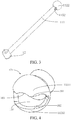
FIG. 3 is a three-dimensional structural diagram of an arm of the UAV shown inFIG. 1 ; -
FIG. 4 is a three-dimensional structural diagram of a spherical hinge housing of the UAV shown inFIG. 1 ; and -
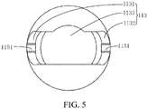
FIG. 5 is a front view of the spherical hinge housing shown inFIG. 4 . - For ease of understanding of the present invention, the present invention is described in further detail below with reference to the accompanying drawings and specific embodiments. It should be noted that when an element is described as being "fixed" to another element, the element may be directly on the another element, or one or more intermediate elements may exist therebetween. When an element is described as being "connected" to another element, the element may be directly connected to the another element, or one or more intermediate elements may exist therebetween. A direction or location relationship indicated by the term "up", "down", "inside", "outside", "bottom", or the like used in the specification is a direction or location relationship shown based on the accompanying drawings, and is only for ease of describing the present invention and simplifying the description, but is not intended to indicate or imply that a mentioned device or element needs to have a particular direction or is constructed and operated in a particular direction. Therefore, the direction or location relationship cannot be understood as a limitation to the present invention. In addition, the terms such as "first", "second" and "third" are used only for the purpose of description, and should not be understood as indicating or implying the relative importance.
- Unless otherwise defined, meanings of all technical and scientific terms used in this specification are the same as meanings usually understood by persons skilled in the technical field to which the present invention belongs. In this specification, terms used in the specification of the present invention are merely intended to describe objectives of the specific embodiments, but are not intended to limit the present invention. A term "and/or" used in this specification includes any or all combinations of one or more related listed items.
- In addition, the technical features provided in the different embodiments of the present invention described below may be combined with each other if no conflict occurs.
- Referring to
FIG. 1 to FIG. 2 together, the embodiments of the present invention provide an unmanned aerial vehicle (UAV) 100, including a power component 10 and avehicle body 20. The power component 10 is mounted on thevehicle body 20 and is configured to supply power to the UAV 100 and drive theUAV 100 to fly. The power component 10 may be further applied to flying toys and the like. - The
vehicle body 20 includes a control circuit component including electronic components such as an MCU. The control circuit component includes a plurality of control modules, for example, a flight control module configured to control a flight attitude of the UAV, a Beidou module or a GPS module configured to navigate the UAV and a data processing module configured to process environmental information obtained by related airborne equipment. - As shown in
FIG. 2 , the power component 10 in the embodiments of the present invention is hinged to thevehicle body 20 by using aspherical hinge portion 112 and may be folded or unfolded relative to thevehicle body 20. The power component 10 includesarms 11, adriving device 12 disposed at one side of thearm 11 and a propeller (not shown in the figure) mounted on thedriving device 12. - As shown in
FIG. 3 and FIG. 4 , thespherical hinge portion 112 includes aspherical hinge housing 1121 disposed on thevehicle body 20 and aspherical hinge 1122 that is accommodated in thespherical hinge housing 1121 and that is connected to a tail end of thearm 11. In another possible embodiment, the spherical hinge housing of the spherical hinge portion may alternatively be disposed on the arm, so that the spherical hinge is disposed on the vehicle body. Thespherical hinge housing 1121 may alternatively be integrally formed with thevehicle body 20. - As shown in
FIG. 4 andFIG. 5 , in an embodiment of the present invention, thespherical hinge housing 1121 includes afirst portion 11211, asecond portion 11212 and anaccommodating space 116 that is surrounded by thefirst portion 11211 and thesecond portion 11212 and that is used for accommodating thespherical hinge 1122. Thefirst portion 11211 has afirst side edge 301, thesecond portion 11212 has asecond side edge 302 disposed at an interval relative to thefirst side edge 301 and anopen slot 113 is formed by a gap between thefirst side edge 301 and thesecond side edge 302. Thearm 11 may slide along theopen slot 113 to be folded or unfolded relative to thevehicle body 20. - In an embodiment of the present invention, the
spherical hinge housing 1121 is hemispheric. In another possible embodiment, thespherical hinge housing 1121 may alternatively be another shape. - In an embodiment of the present invention, the
UAV 100 may further include a limiting structure 115 (as shown inFIG. 2 ). Thelimiting structure 115 is configured to prevent thearm 11 from rotating relative to thevehicle body 20 when thearm 11 is in a folded or unfolded state. - In an embodiment of the present invention, the
limiting structure 115 may further include a first clamping portion disposed on thespherical hinge housing 1121 and a second clamping portion that is disposed on anarm body 111 and that is clamped to the first clamping portion. In an embodiment of the present invention, the first clamping portion isclamping slots 1151 that are disposed on thespherical hinge housing 1121 and that are respectively located on both sides of theopen slot 113 and the second clamping portion is aclamping block 1152 that is disposed on thearm body 111 and that is clamped to theclamping slot 1151. In another possible embodiment, the first clamping portion may alternatively be a clamping block disposed on the spherical hinge housing and the second clamping portion is correspondingly a clamping slot that is disposed on the arm body and that is clamped to the clamping block. - When the
arm 11 slides to two sides in theopen slot 113, that is, in a folded or unfolded state, thearm 11 is located in a manner in which theclamping block 1152 on thearm 11 is clamped to theclamping slot 1151 on thespherical hinge housing 1121, to prevent thearm 11 from unnecessarily rotating relative to thearm 20. - In an embodiment of the present invention, to avoid the
clamping block 1152 on thearm 11 during rotating of thearm 11, thefirst side edge 301 of thefirst portion 11211 of thespherical hinge housing 1121 is provided with an arc-shapedside edge 303. As shown inFIG. 5 , in the process that theclamping block 1152 is separated from theclamping slot 1151 located at the left side of the figure and is unfolded to right, thearm 11 needs to be rotated, so that theclamping block 1152 faces theclamping slot 1151 located at the right side of the figure. Therefore, to enable thearm 11 to smoothly rotate, the arc-shapedside edge 303 bent in the direction away from theopen slot 113 is arranged on thefirst side edge 301. It should be understood that, alternatively, thearm 11 may be provided with two clamping blocks or the open slot may be expanded, and the arc-shapedside edge 303 may be omitted. - In some other possible embodiments, an arc-shaped side edge used for avoiding the clamping block may alternatively be provided on the
second side edge 302. Alternatively, thefirst side edge 301 and thesecond side edge 302 are both provided with an arc-shaped side edge used for avoiding the clamping block. - As shown in
FIG. 5 , in an embodiment of the present invention, theopen slot 113 includes a firstcircular opening 1131, a second circular opening 1132 and a thirdcircular opening 1133. The thirdcircular opening 1133 is located between the firstcircular opening 1131 and the second circular opening 1132, and the thirdcircular opening 1133 is in communication with the firstcircular opening 1131 and the second circular opening 1132. - A cross-sectional shape of the
arm body 111 is circular. Thearm body 111 may slide in an opening of theopen slot 113 and may be stuck by any of the firstcircular opening 1131 and the second circular opening 1132. When thearm body 111 is stuck in the firstcircular opening 1131, theclamping block 1152 is embedded in theclamping slot 1151 and is stuck by theclamping slot 1151. Thearm body 111 is stuck in the firstcircular opening 1131, to prevent thearm body 111 from sliding in theopen slot 113. When thearm body 111 is stuck by the second circular opening 1132, theclamping block 1152 is embedded in theother clamping slot 1151 and is stuck by theother clamping slot 1151. Thearm body 111 is stuck in the second circular opening 1132, to prevent thearm body 111 from sliding. - A size of the first circular opening 1132 is equal to a size of the second
circular opening 1133, and a diameter of the thirdcircular opening 1133 is greater than a diameter of the firstcircular opening 1131. During folding or unfolding, thearm body 111 first slides from the firstcircular opening 1131 to the thirdcircular opening 1133, and rotates by 180 degrees in the thirdcircular opening 1133. A diameter of thearm body 111 is equal to the diameter of the firstcircular opening 1131 and the second circular opening 1132. Therefore, due to theclamping block 1152, thearm body 111 cannot rotate in the firstcircular opening 1131 or the second circular opening 1132. Thearm body 111 after rotation may successfully enter the second circular opening 1132 and theclamping block 1152 is embedded in theother clamping slot 1151. - It may be understood that, in some other embodiments, the first clamping portion is clamping blocks that are disposed on the spherical hinge housing and that are respectively located on both sides of the open slot and the second clamping portion is a clamping slot. There are two clamping
blocks 1152 in total, which are both disposed on opposite sides of one end of thearm body 111. A connecting line of the twoclamping blocks 1152 is perpendicularly intersects an axis of thearm body 111. The twoclamping blocks 1152 are respectively disposed at locations of the two clampingslots 1151 in the embodiment shown inFIG. 5 . Thearm body 111 is provided with the two clampingslots 1151. That is, theclamping slot 1151 is disposed at the location of theclamping block 1152 in the embodiment shown inFIG. 3 . - During a flight, the
arm 11 is in an unfolded state. When thearm body 111 is stuck in the firstcircular opening 1131, theclamping block 1152 is embedded in theclamping slot 1151 shown on the left side ofFIG. 5 and is stuck by theclamping slot 1151. Thearm 11 is fully fixed. The drivingdevice 12 disposed at the other end of thearm 11 provides power for theUAV 100, to drive theUAV 100 to fly. - After the flight ends, the
arm body 111 first slides to the thirdcircular opening 1133, so that theclamping block 1152 on thearm body 111 is separated from theclamping slot 1151 shown on the left side ofFIG. 5 and rotates by 180 degrees in the thirdcircular opening 1133, so that theclamping block 1152 faces theclamping slot 1151 shown on the right side ofFIG. 5 . Then, thearm body 111 slides from the thirdcircular opening 1133 to the second circular opening 1132, so that thearm body 111 is stuck in the second circular opening 1132, and theclamping block 1152 is embedded in theclamping slot 1151 shown on the right side ofFIG. 5 and is stuck by theother clamping slot 1151. In this case, thearm 11 is folded. Next, the propeller is folded (if possible), so that the power component 10 tightly clings to two opposite sides of thevehicle body 20. - Based on the foregoing structure design, compared with the existing manner of folding arms of the UAV, the
arm 11 in the embodiments of the present invention are hinged to thevehicle body 20 of theUAV 100 by using thespherical hinge portion 112. The arm can be folded and unfolded smoothly without interference, which conforms to known operation habits of users, so that the structure becomes more compact and easier to carry. In addition, it can be effectively avoided that the UAV is damaged due to impact in the carrying process. - Finally, it should be noted that the foregoing embodiments are merely intended for describing the technical solutions of the present invention other than limiting the present invention. Under the idea of the present invention, technical features in the foregoing embodiments or different embodiments may be combined, steps may be implemented in any sequence and many changes such as the foregoing different aspects of the present invention may exist, which are not provided in detail for brevity. Although the present invention is described in detail with reference to the foregoing embodiments, persons of ordinary skill in the art should understand that they may still make modifications to the technical solutions described in the foregoing embodiments or make equivalent replacements to some technical features thereof, without departing from the scope of the technical solutions of the embodiments of the present invention.
Claims (9)
- An unmanned aerial vehicle (UAV), comprising a vehicle body and arms connected to the vehicle body, wherein the arm is hinged to the vehicle body by using a spherical hinge portion and is folded or unfolded relative to the vehicle body.
- The UAV according to claim 1, wherein the spherical hinge portion comprises a spherical hinge housing disposed on the vehicle body and a spherical hinge that is accommodated in the spherical hinge housing and that is connected to the arm.
- The UAV according to claim 1, wherein the spherical hinge portion comprises a spherical hinge housing disposed on the arm and a spherical hinge that is accommodated in the spherical hinge housing and that is connected to the vehicle body.
- The UAV according to claim 2 or 3, wherein the UAV further comprises a limiting structure configured to prevent the arm from rotating relative to the vehicle body when the arm is in a folded or unfolded state, the limiting structure comprising a first clamping portion disposed on the spherical hinge housing and a second clamping portion that is disposed on the arm and that is clamped to the first clamping portion.
- The UAV according to claim 2 or 4, wherein the spherical hinge housing is further provided with an open slot in a folding or unfolding direction of the arm, the first clamping portion is clamping slots that are disposed on the spherical hinge housing and that are respectively located on both sides of the open slot and the second clamping portion is a clamping block disposed on the arm.
- The UAV according to claim 2 or 4, wherein the spherical hinge housing is further provided with an open slot in a folding or unfolding direction of the arm, the first clamping portion is clamping blocks that are disposed on the spherical hinge housing and that are respectively located on both sides of the open slot and the second clamping portion is a clamping slot disposed on the arm.
- The UAV according to claim 5 or 6, wherein
the spherical hinge housing comprises a first portion, a second portion and an accommodating space that is surrounded by the first portion and the second portion and that is used for accommodating the spherical hinge; and
the first portion has a first side edge, the second portion has a second side edge disposed at an interval relative to the first side edge and the open slot is formed by a gap between the first side edge and the second side edge. - The UAV according to claim 7, wherein the first side edge and/or the second side edge are/is further provided with an arc-shaped side edge used for avoiding the second clamping portion.
- The UAV according to claim 2 or 8, wherein the spherical hinge housing is hemispheric.
Applications Claiming Priority (2)
| Application Number | Priority Date | Filing Date | Title |
|---|---|---|---|
| CN201710601093.7A CN109278993B (en) | 2017-07-21 | 2017-07-21 | Unmanned aerial vehicle |
| PCT/CN2018/083758 WO2019015366A1 (en) | 2017-07-21 | 2018-04-19 | Unmanned aerial vehicle |
Publications (3)
| Publication Number | Publication Date |
|---|---|
| EP3643602A1 true EP3643602A1 (en) | 2020-04-29 |
| EP3643602A4 EP3643602A4 (en) | 2020-06-17 |
| EP3643602B1 EP3643602B1 (en) | 2021-10-20 |
Family
ID=65014988
Family Applications (1)
| Application Number | Title | Priority Date | Filing Date |
|---|---|---|---|
| EP18834347.9A Active EP3643602B1 (en) | 2017-07-21 | 2018-04-19 | Unmanned aerial vehicle |
Country Status (4)
| Country | Link |
|---|---|
| US (1) | US11492112B2 (en) |
| EP (1) | EP3643602B1 (en) |
| CN (1) | CN109278993B (en) |
| WO (1) | WO2019015366A1 (en) |
Family Cites Families (21)
| Publication number | Priority date | Publication date | Assignee | Title |
|---|---|---|---|---|
| CH608874A5 (en) * | 1976-11-16 | 1979-01-31 | Meier Karl Tekusa | Stand having three hinges |
| DE102005014949A1 (en) * | 2005-04-01 | 2006-10-05 | Dolch, Stefan, Dipl.-Ing. (FH) | Multi-rotor helicopter e.g. reconnaissance drone for urban areas, has support frame divided into at least two groups of structures mechanically connected together as such that electrical connection between groups is possible |
| RU2371351C2 (en) * | 2005-04-20 | 2009-10-27 | Казанский государственный технический университет им. А.Н. Туполева | Method to control rotor of rotary wing flying vehicle and device to this end |
| AU2005331991B2 (en) * | 2005-05-20 | 2011-09-29 | Foto Ottica Cescon Di Cescon Stefano | Spherical joint |
| CN101837195B (en) * | 2010-01-21 | 2012-02-08 | 罗之洪 | Model airplane with vertical takeoff and landing |
| AT510493A1 (en) * | 2010-09-22 | 2012-04-15 | Franz Ing Kutschi | HELICOPTER |
| CN102556336A (en) * | 2011-12-30 | 2012-07-11 | 北京理工大学 | Wing fast unfolding device for folding-wing unmanned plane |
| WO2014059549A1 (en) * | 2012-10-19 | 2014-04-24 | Aeryon Labs Inc | Hovering unmanned aerial vehicle |
| WO2014097292A1 (en) * | 2012-12-18 | 2014-06-26 | Rafael Advanced Defense Systems Ltd. | Wing deployment mechanism |
| GB201307739D0 (en) * | 2013-04-30 | 2013-06-12 | Reiter Johannes | Aircraft for vertical take-off and landing with hinged and bendable wings |
| JP2015112929A (en) * | 2013-12-10 | 2015-06-22 | 須知 晃一 | Manufacturing method and components of flying body for individual's aerial work |
| EP3206947B1 (en) * | 2015-06-01 | 2021-07-07 | SZ DJI Technology Co., Ltd. | Systems and methods for foldable arms |
| CN105000163B (en) * | 2015-08-23 | 2017-12-08 | 代一泓 | A kind of more rotor unmanned aircrafts of fold-down formula |
| CN105314088A (en) * | 2015-11-06 | 2016-02-10 | 珠海华迈航空科技有限公司 | Four-rotor craft |
| CN205168886U (en) * | 2015-11-26 | 2016-04-20 | 深圳智航无人机有限公司 | Folding unmanned vehicles |
| US10035581B2 (en) * | 2016-01-12 | 2018-07-31 | Draganfly Innovations, Inc. | Multi-rotor UAV with compact folding rotor arms |
| EP3419894B1 (en) * | 2016-02-22 | 2021-11-10 | SZ DJI Technology Co., Ltd. | Foldable multi-rotor aerial vehicle |
| CN105703528A (en) * | 2016-03-16 | 2016-06-22 | 何国华 | Steering wheel hub system for ball hinge universal rotary motor |
| CN106394886A (en) * | 2016-06-15 | 2017-02-15 | 珠海市磐石电子科技有限公司 | Multi-axis aircraft capable of movably flying, flying assisting platform and flying method |
| CN106741895A (en) * | 2016-12-28 | 2017-05-31 | 合肥工业大学 | The operating method of inspection unmanned plane violating the regulations and inspection unmanned plane violating the regulations |
| CN207631482U (en) * | 2017-07-21 | 2018-07-20 | 深圳市道通智能航空技术有限公司 | Unmanned vehicle |
-
2017
- 2017-07-21 CN CN201710601093.7A patent/CN109278993B/en active Active
-
2018
- 2018-04-19 EP EP18834347.9A patent/EP3643602B1/en active Active
- 2018-04-19 WO PCT/CN2018/083758 patent/WO2019015366A1/en not_active Ceased
-
2020
- 2020-01-20 US US16/747,180 patent/US11492112B2/en active Active
Also Published As
| Publication number | Publication date |
|---|---|
| US20200148353A1 (en) | 2020-05-14 |
| WO2019015366A1 (en) | 2019-01-24 |
| US11492112B2 (en) | 2022-11-08 |
| CN109278993B (en) | 2024-09-13 |
| EP3643602A4 (en) | 2020-06-17 |
| EP3643602B1 (en) | 2021-10-20 |
| CN109278993A (en) | 2019-01-29 |
Similar Documents
| Publication | Publication Date | Title |
|---|---|---|
| US10730619B2 (en) | Arm and unmanned aerial vehicle | |
| CN108216593B (en) | Landing gear and unmanned aerial vehicle having the same | |
| CN113911326B (en) | Unmanned aerial vehicles | |
| CN109383739B (en) | Horn and unmanned aerial vehicle | |
| KR102451679B1 (en) | Unmanned aerial vehicle | |
| EP3321180A1 (en) | Propeller unit deployment-type unmanned aerial vehicle | |
| CN108146618B (en) | Undercarriage and unmanned aerial vehicle with same | |
| US20170313400A1 (en) | Collapsible unmanned aerial vehicle (uav) | |
| EP3453615B1 (en) | Antenna and unmanned aerial vehicle | |
| WO2018182883A1 (en) | Double folding drone arms with landing gear | |
| WO2019056865A1 (en) | Pan-tilt and unmanned aerial vehicle having same | |
| US12256172B2 (en) | Advanced manufacturing technologies and machine learning in unmanned aviation systems | |
| US11254444B2 (en) | Gimbal, photographing apparatus having same, and unmanned aerial vehicle | |
| WO2018157833A1 (en) | Novel unmanned aerial vehicle | |
| US20240034483A1 (en) | Aviation integrated optics and lighting unit | |
| US20190248502A1 (en) | Battery compartment | |
| CN112954092B (en) | Electronic equipment | |
| US11492112B2 (en) | Unmanned aerial vehicle | |
| WO2019144673A1 (en) | Lens assembly and mobile terminal | |
| CN207631482U (en) | Unmanned vehicle | |
| US11811130B2 (en) | Single axis articulating antenna positioner for tube launched or conformal applications | |
| CN206797696U (en) | A kind of new unmanned plane | |
| CN109204856B (en) | Tripod head and unmanned aerial vehicle with same | |
| WO2019120214A1 (en) | Two-axis gimbal system | |
| CN215514168U (en) | Visual sensing device and aircraft |
Legal Events
| Date | Code | Title | Description |
|---|---|---|---|
| STAA | Information on the status of an ep patent application or granted ep patent |
Free format text: STATUS: THE INTERNATIONAL PUBLICATION HAS BEEN MADE |
|
| PUAI | Public reference made under article 153(3) epc to a published international application that has entered the european phase |
Free format text: ORIGINAL CODE: 0009012 |
|
| STAA | Information on the status of an ep patent application or granted ep patent |
Free format text: STATUS: REQUEST FOR EXAMINATION WAS MADE |
|
| 17P | Request for examination filed |
Effective date: 20200121 |
|
| AK | Designated contracting states |
Kind code of ref document: A1 Designated state(s): AL AT BE BG CH CY CZ DE DK EE ES FI FR GB GR HR HU IE IS IT LI LT LU LV MC MK MT NL NO PL PT RO RS SE SI SK SM TR |
|
| AX | Request for extension of the european patent |
Extension state: BA ME |
|
| A4 | Supplementary search report drawn up and despatched |
Effective date: 20200520 |
|
| RIC1 | Information provided on ipc code assigned before grant |
Ipc: B64C 39/02 20060101ALI20200514BHEP Ipc: B64C 3/56 20060101AFI20200514BHEP |
|
| DAV | Request for validation of the european patent (deleted) | ||
| DAX | Request for extension of the european patent (deleted) | ||
| RIC1 | Information provided on ipc code assigned before grant |
Ipc: B64C 39/02 20060101ALI20210331BHEP Ipc: B64C 3/56 20060101AFI20210331BHEP |
|
| GRAP | Despatch of communication of intention to grant a patent |
Free format text: ORIGINAL CODE: EPIDOSNIGR1 |
|
| STAA | Information on the status of an ep patent application or granted ep patent |
Free format text: STATUS: GRANT OF PATENT IS INTENDED |
|
| INTG | Intention to grant announced |
Effective date: 20210514 |
|
| GRAS | Grant fee paid |
Free format text: ORIGINAL CODE: EPIDOSNIGR3 |
|
| GRAA | (expected) grant |
Free format text: ORIGINAL CODE: 0009210 |
|
| STAA | Information on the status of an ep patent application or granted ep patent |
Free format text: STATUS: THE PATENT HAS BEEN GRANTED |
|
| AK | Designated contracting states |
Kind code of ref document: B1 Designated state(s): AL AT BE BG CH CY CZ DE DK EE ES FI FR GB GR HR HU IE IS IT LI LT LU LV MC MK MT NL NO PL PT RO RS SE SI SK SM TR |
|
| REG | Reference to a national code |
Ref country code: GB Ref legal event code: FG4D |
|
| REG | Reference to a national code |
Ref country code: CH Ref legal event code: EP |
|
| REG | Reference to a national code |
Ref country code: DE Ref legal event code: R096 Ref document number: 602018025484 Country of ref document: DE |
|
| REG | Reference to a national code |
Ref country code: IE Ref legal event code: FG4D |
|
| REG | Reference to a national code |
Ref country code: AT Ref legal event code: REF Ref document number: 1439728 Country of ref document: AT Kind code of ref document: T Effective date: 20211115 |
|
| REG | Reference to a national code |
Ref country code: LT Ref legal event code: MG9D |
|
| REG | Reference to a national code |
Ref country code: NL Ref legal event code: MP Effective date: 20211020 |
|
| REG | Reference to a national code |
Ref country code: AT Ref legal event code: MK05 Ref document number: 1439728 Country of ref document: AT Kind code of ref document: T Effective date: 20211020 |
|
| PG25 | Lapsed in a contracting state [announced via postgrant information from national office to epo] |
Ref country code: RS Free format text: LAPSE BECAUSE OF FAILURE TO SUBMIT A TRANSLATION OF THE DESCRIPTION OR TO PAY THE FEE WITHIN THE PRESCRIBED TIME-LIMIT Effective date: 20211020 Ref country code: LT Free format text: LAPSE BECAUSE OF FAILURE TO SUBMIT A TRANSLATION OF THE DESCRIPTION OR TO PAY THE FEE WITHIN THE PRESCRIBED TIME-LIMIT Effective date: 20211020 Ref country code: FI Free format text: LAPSE BECAUSE OF FAILURE TO SUBMIT A TRANSLATION OF THE DESCRIPTION OR TO PAY THE FEE WITHIN THE PRESCRIBED TIME-LIMIT Effective date: 20211020 Ref country code: BG Free format text: LAPSE BECAUSE OF FAILURE TO SUBMIT A TRANSLATION OF THE DESCRIPTION OR TO PAY THE FEE WITHIN THE PRESCRIBED TIME-LIMIT Effective date: 20220120 Ref country code: AT Free format text: LAPSE BECAUSE OF FAILURE TO SUBMIT A TRANSLATION OF THE DESCRIPTION OR TO PAY THE FEE WITHIN THE PRESCRIBED TIME-LIMIT Effective date: 20211020 |
|
| PG25 | Lapsed in a contracting state [announced via postgrant information from national office to epo] |
Ref country code: IS Free format text: LAPSE BECAUSE OF FAILURE TO SUBMIT A TRANSLATION OF THE DESCRIPTION OR TO PAY THE FEE WITHIN THE PRESCRIBED TIME-LIMIT Effective date: 20220220 Ref country code: SE Free format text: LAPSE BECAUSE OF FAILURE TO SUBMIT A TRANSLATION OF THE DESCRIPTION OR TO PAY THE FEE WITHIN THE PRESCRIBED TIME-LIMIT Effective date: 20211020 Ref country code: PT Free format text: LAPSE BECAUSE OF FAILURE TO SUBMIT A TRANSLATION OF THE DESCRIPTION OR TO PAY THE FEE WITHIN THE PRESCRIBED TIME-LIMIT Effective date: 20220221 Ref country code: PL Free format text: LAPSE BECAUSE OF FAILURE TO SUBMIT A TRANSLATION OF THE DESCRIPTION OR TO PAY THE FEE WITHIN THE PRESCRIBED TIME-LIMIT Effective date: 20211020 Ref country code: NO Free format text: LAPSE BECAUSE OF FAILURE TO SUBMIT A TRANSLATION OF THE DESCRIPTION OR TO PAY THE FEE WITHIN THE PRESCRIBED TIME-LIMIT Effective date: 20220120 Ref country code: NL Free format text: LAPSE BECAUSE OF FAILURE TO SUBMIT A TRANSLATION OF THE DESCRIPTION OR TO PAY THE FEE WITHIN THE PRESCRIBED TIME-LIMIT Effective date: 20211020 Ref country code: LV Free format text: LAPSE BECAUSE OF FAILURE TO SUBMIT A TRANSLATION OF THE DESCRIPTION OR TO PAY THE FEE WITHIN THE PRESCRIBED TIME-LIMIT Effective date: 20211020 Ref country code: HR Free format text: LAPSE BECAUSE OF FAILURE TO SUBMIT A TRANSLATION OF THE DESCRIPTION OR TO PAY THE FEE WITHIN THE PRESCRIBED TIME-LIMIT Effective date: 20211020 Ref country code: GR Free format text: LAPSE BECAUSE OF FAILURE TO SUBMIT A TRANSLATION OF THE DESCRIPTION OR TO PAY THE FEE WITHIN THE PRESCRIBED TIME-LIMIT Effective date: 20220121 Ref country code: ES Free format text: LAPSE BECAUSE OF FAILURE TO SUBMIT A TRANSLATION OF THE DESCRIPTION OR TO PAY THE FEE WITHIN THE PRESCRIBED TIME-LIMIT Effective date: 20211020 |
|
| REG | Reference to a national code |
Ref country code: DE Ref legal event code: R097 Ref document number: 602018025484 Country of ref document: DE |
|
| PG25 | Lapsed in a contracting state [announced via postgrant information from national office to epo] |
Ref country code: SM Free format text: LAPSE BECAUSE OF FAILURE TO SUBMIT A TRANSLATION OF THE DESCRIPTION OR TO PAY THE FEE WITHIN THE PRESCRIBED TIME-LIMIT Effective date: 20211020 Ref country code: SK Free format text: LAPSE BECAUSE OF FAILURE TO SUBMIT A TRANSLATION OF THE DESCRIPTION OR TO PAY THE FEE WITHIN THE PRESCRIBED TIME-LIMIT Effective date: 20211020 Ref country code: RO Free format text: LAPSE BECAUSE OF FAILURE TO SUBMIT A TRANSLATION OF THE DESCRIPTION OR TO PAY THE FEE WITHIN THE PRESCRIBED TIME-LIMIT Effective date: 20211020 Ref country code: EE Free format text: LAPSE BECAUSE OF FAILURE TO SUBMIT A TRANSLATION OF THE DESCRIPTION OR TO PAY THE FEE WITHIN THE PRESCRIBED TIME-LIMIT Effective date: 20211020 Ref country code: DK Free format text: LAPSE BECAUSE OF FAILURE TO SUBMIT A TRANSLATION OF THE DESCRIPTION OR TO PAY THE FEE WITHIN THE PRESCRIBED TIME-LIMIT Effective date: 20211020 Ref country code: CZ Free format text: LAPSE BECAUSE OF FAILURE TO SUBMIT A TRANSLATION OF THE DESCRIPTION OR TO PAY THE FEE WITHIN THE PRESCRIBED TIME-LIMIT Effective date: 20211020 |
|
| PLBE | No opposition filed within time limit |
Free format text: ORIGINAL CODE: 0009261 |
|
| STAA | Information on the status of an ep patent application or granted ep patent |
Free format text: STATUS: NO OPPOSITION FILED WITHIN TIME LIMIT |
|
| 26N | No opposition filed |
Effective date: 20220721 |
|
| PG25 | Lapsed in a contracting state [announced via postgrant information from national office to epo] |
Ref country code: AL Free format text: LAPSE BECAUSE OF FAILURE TO SUBMIT A TRANSLATION OF THE DESCRIPTION OR TO PAY THE FEE WITHIN THE PRESCRIBED TIME-LIMIT Effective date: 20211020 |
|
| PG25 | Lapsed in a contracting state [announced via postgrant information from national office to epo] |
Ref country code: SI Free format text: LAPSE BECAUSE OF FAILURE TO SUBMIT A TRANSLATION OF THE DESCRIPTION OR TO PAY THE FEE WITHIN THE PRESCRIBED TIME-LIMIT Effective date: 20211020 |
|
| REG | Reference to a national code |
Ref country code: CH Ref legal event code: PL |
|
| REG | Reference to a national code |
Ref country code: BE Ref legal event code: MM Effective date: 20220430 |
|
| PG25 | Lapsed in a contracting state [announced via postgrant information from national office to epo] |
Ref country code: MC Free format text: LAPSE BECAUSE OF FAILURE TO SUBMIT A TRANSLATION OF THE DESCRIPTION OR TO PAY THE FEE WITHIN THE PRESCRIBED TIME-LIMIT Effective date: 20211020 Ref country code: LU Free format text: LAPSE BECAUSE OF NON-PAYMENT OF DUE FEES Effective date: 20220419 Ref country code: LI Free format text: LAPSE BECAUSE OF NON-PAYMENT OF DUE FEES Effective date: 20220430 Ref country code: CH Free format text: LAPSE BECAUSE OF NON-PAYMENT OF DUE FEES Effective date: 20220430 |
|
| PG25 | Lapsed in a contracting state [announced via postgrant information from national office to epo] |
Ref country code: BE Free format text: LAPSE BECAUSE OF NON-PAYMENT OF DUE FEES Effective date: 20220430 |
|
| PG25 | Lapsed in a contracting state [announced via postgrant information from national office to epo] |
Ref country code: IE Free format text: LAPSE BECAUSE OF NON-PAYMENT OF DUE FEES Effective date: 20220419 |
|
| PG25 | Lapsed in a contracting state [announced via postgrant information from national office to epo] |
Ref country code: IT Free format text: LAPSE BECAUSE OF FAILURE TO SUBMIT A TRANSLATION OF THE DESCRIPTION OR TO PAY THE FEE WITHIN THE PRESCRIBED TIME-LIMIT Effective date: 20211020 |
|
| PG25 | Lapsed in a contracting state [announced via postgrant information from national office to epo] |
Ref country code: MK Free format text: LAPSE BECAUSE OF FAILURE TO SUBMIT A TRANSLATION OF THE DESCRIPTION OR TO PAY THE FEE WITHIN THE PRESCRIBED TIME-LIMIT Effective date: 20211020 Ref country code: CY Free format text: LAPSE BECAUSE OF FAILURE TO SUBMIT A TRANSLATION OF THE DESCRIPTION OR TO PAY THE FEE WITHIN THE PRESCRIBED TIME-LIMIT Effective date: 20211020 |
|
| PG25 | Lapsed in a contracting state [announced via postgrant information from national office to epo] |
Ref country code: HU Free format text: LAPSE BECAUSE OF FAILURE TO SUBMIT A TRANSLATION OF THE DESCRIPTION OR TO PAY THE FEE WITHIN THE PRESCRIBED TIME-LIMIT; INVALID AB INITIO Effective date: 20180419 |
|
| PGFP | Annual fee paid to national office [announced via postgrant information from national office to epo] |
Ref country code: GB Payment date: 20240419 Year of fee payment: 7 |
|
| PG25 | Lapsed in a contracting state [announced via postgrant information from national office to epo] |
Ref country code: MT Free format text: LAPSE BECAUSE OF FAILURE TO SUBMIT A TRANSLATION OF THE DESCRIPTION OR TO PAY THE FEE WITHIN THE PRESCRIBED TIME-LIMIT Effective date: 20211020 |
|
| PGFP | Annual fee paid to national office [announced via postgrant information from national office to epo] |
Ref country code: DE Payment date: 20250422 Year of fee payment: 8 |
|
| PGFP | Annual fee paid to national office [announced via postgrant information from national office to epo] |
Ref country code: FR Payment date: 20250425 Year of fee payment: 8 |
|
| PG25 | Lapsed in a contracting state [announced via postgrant information from national office to epo] |
Ref country code: TR Free format text: LAPSE BECAUSE OF FAILURE TO SUBMIT A TRANSLATION OF THE DESCRIPTION OR TO PAY THE FEE WITHIN THE PRESCRIBED TIME-LIMIT Effective date: 20211020 |
|
| GBPC | Gb: european patent ceased through non-payment of renewal fee |
Effective date: 20250419 |
|
| PG25 | Lapsed in a contracting state [announced via postgrant information from national office to epo] |
Ref country code: GB Free format text: LAPSE BECAUSE OF NON-PAYMENT OF DUE FEES Effective date: 20250419 |