EP3643539A1 - Run-flat tire - Google Patents
Run-flat tire Download PDFInfo
- Publication number
- EP3643539A1 EP3643539A1 EP18821545.3A EP18821545A EP3643539A1 EP 3643539 A1 EP3643539 A1 EP 3643539A1 EP 18821545 A EP18821545 A EP 18821545A EP 3643539 A1 EP3643539 A1 EP 3643539A1
- Authority
- EP
- European Patent Office
- Prior art keywords
- tire
- bead
- carcass
- run
- radial direction
- Prior art date
- Legal status (The legal status is an assumption and is not a legal conclusion. Google has not performed a legal analysis and makes no representation as to the accuracy of the status listed.)
- Granted
Links
Images


Classifications
-
- B—PERFORMING OPERATIONS; TRANSPORTING
- B60—VEHICLES IN GENERAL
- B60C—VEHICLE TYRES; TYRE INFLATION; TYRE CHANGING; CONNECTING VALVES TO INFLATABLE ELASTIC BODIES IN GENERAL; DEVICES OR ARRANGEMENTS RELATED TO TYRES
- B60C17/00—Tyres characterised by means enabling restricted operation in damaged or deflated condition; Accessories therefor
- B60C17/0009—Tyres characterised by means enabling restricted operation in damaged or deflated condition; Accessories therefor comprising sidewall rubber inserts, e.g. crescent shaped inserts
-
- B—PERFORMING OPERATIONS; TRANSPORTING
- B29—WORKING OF PLASTICS; WORKING OF SUBSTANCES IN A PLASTIC STATE IN GENERAL
- B29D—PRODUCING PARTICULAR ARTICLES FROM PLASTICS OR FROM SUBSTANCES IN A PLASTIC STATE
- B29D30/00—Producing pneumatic or solid tyres or parts thereof
- B29D30/06—Pneumatic tyres or parts thereof (e.g. produced by casting, moulding, compression moulding, injection moulding, centrifugal casting)
- B29D30/08—Building tyres
- B29D30/20—Building tyres by the flat-tyre method, i.e. building on cylindrical drums
- B29D30/30—Applying the layers; Guiding or stretching the layers during application
- B29D30/3028—Applying the layers; Guiding or stretching the layers during application by feeding a continuous band and winding it helically, i.e. the band is fed while being advanced along the drum axis, to form an annular element
-
- B—PERFORMING OPERATIONS; TRANSPORTING
- B29—WORKING OF PLASTICS; WORKING OF SUBSTANCES IN A PLASTIC STATE IN GENERAL
- B29D—PRODUCING PARTICULAR ARTICLES FROM PLASTICS OR FROM SUBSTANCES IN A PLASTIC STATE
- B29D30/00—Producing pneumatic or solid tyres or parts thereof
- B29D30/06—Pneumatic tyres or parts thereof (e.g. produced by casting, moulding, compression moulding, injection moulding, centrifugal casting)
- B29D30/70—Annular breakers
-
- B—PERFORMING OPERATIONS; TRANSPORTING
- B60—VEHICLES IN GENERAL
- B60C—VEHICLE TYRES; TYRE INFLATION; TYRE CHANGING; CONNECTING VALVES TO INFLATABLE ELASTIC BODIES IN GENERAL; DEVICES OR ARRANGEMENTS RELATED TO TYRES
- B60C15/00—Tyre beads, e.g. ply turn-up or overlap
- B60C15/0009—Tyre beads, e.g. ply turn-up or overlap features of the carcass terminal portion
- B60C15/0036—Tyre beads, e.g. ply turn-up or overlap features of the carcass terminal portion with high ply turn-up, i.e. folded around the bead core and terminating radially above the point of maximum section width
-
- B—PERFORMING OPERATIONS; TRANSPORTING
- B60—VEHICLES IN GENERAL
- B60C—VEHICLE TYRES; TYRE INFLATION; TYRE CHANGING; CONNECTING VALVES TO INFLATABLE ELASTIC BODIES IN GENERAL; DEVICES OR ARRANGEMENTS RELATED TO TYRES
- B60C15/00—Tyre beads, e.g. ply turn-up or overlap
- B60C15/04—Bead cores
- B60C15/05—Bead cores multiple, i.e. with two or more cores in each bead
-
- B—PERFORMING OPERATIONS; TRANSPORTING
- B60—VEHICLES IN GENERAL
- B60C—VEHICLE TYRES; TYRE INFLATION; TYRE CHANGING; CONNECTING VALVES TO INFLATABLE ELASTIC BODIES IN GENERAL; DEVICES OR ARRANGEMENTS RELATED TO TYRES
- B60C9/00—Reinforcements or ply arrangement of pneumatic tyres
- B60C9/18—Structure or arrangement of belts or breakers, crown-reinforcing or cushioning layers
- B60C9/20—Structure or arrangement of belts or breakers, crown-reinforcing or cushioning layers built-up from rubberised plies each having all cords arranged substantially parallel
- B60C9/22—Structure or arrangement of belts or breakers, crown-reinforcing or cushioning layers built-up from rubberised plies each having all cords arranged substantially parallel the plies being arranged with all cords disposed along the circumference of the tyre
- B60C9/2204—Structure or arrangement of belts or breakers, crown-reinforcing or cushioning layers built-up from rubberised plies each having all cords arranged substantially parallel the plies being arranged with all cords disposed along the circumference of the tyre obtained by circumferentially narrow strip winding
-
- B—PERFORMING OPERATIONS; TRANSPORTING
- B29—WORKING OF PLASTICS; WORKING OF SUBSTANCES IN A PLASTIC STATE IN GENERAL
- B29D—PRODUCING PARTICULAR ARTICLES FROM PLASTICS OR FROM SUBSTANCES IN A PLASTIC STATE
- B29D30/00—Producing pneumatic or solid tyres or parts thereof
- B29D30/06—Pneumatic tyres or parts thereof (e.g. produced by casting, moulding, compression moulding, injection moulding, centrifugal casting)
- B29D30/0681—Parts of pneumatic tyres; accessories, auxiliary operations
- B29D2030/0683—Additional internal supports to be positioned inside the tyre, as emergency supports for run-flat tyres
-
- B—PERFORMING OPERATIONS; TRANSPORTING
- B29—WORKING OF PLASTICS; WORKING OF SUBSTANCES IN A PLASTIC STATE IN GENERAL
- B29D—PRODUCING PARTICULAR ARTICLES FROM PLASTICS OR FROM SUBSTANCES IN A PLASTIC STATE
- B29D30/00—Producing pneumatic or solid tyres or parts thereof
- B29D30/06—Pneumatic tyres or parts thereof (e.g. produced by casting, moulding, compression moulding, injection moulding, centrifugal casting)
- B29D30/72—Side-walls
- B29D2030/724—Stiffening the sidewalls, e.g. by using additional inserts, e.g. made of rubber, plastics or other materials
-
- B—PERFORMING OPERATIONS; TRANSPORTING
- B60—VEHICLES IN GENERAL
- B60C—VEHICLE TYRES; TYRE INFLATION; TYRE CHANGING; CONNECTING VALVES TO INFLATABLE ELASTIC BODIES IN GENERAL; DEVICES OR ARRANGEMENTS RELATED TO TYRES
- B60C1/00—Tyres characterised by the chemical composition or the physical arrangement or mixture of the composition
- B60C2001/005—Compositions of the bead portions, e.g. clinch or chafer rubber or cushion rubber
- B60C2001/0058—Compositions of the bead apexes
-
- B—PERFORMING OPERATIONS; TRANSPORTING
- B60—VEHICLES IN GENERAL
- B60C—VEHICLE TYRES; TYRE INFLATION; TYRE CHANGING; CONNECTING VALVES TO INFLATABLE ELASTIC BODIES IN GENERAL; DEVICES OR ARRANGEMENTS RELATED TO TYRES
- B60C1/00—Tyres characterised by the chemical composition or the physical arrangement or mixture of the composition
- B60C2001/0083—Compositions of the cap ply layers
-
- B—PERFORMING OPERATIONS; TRANSPORTING
- B60—VEHICLES IN GENERAL
- B60C—VEHICLE TYRES; TYRE INFLATION; TYRE CHANGING; CONNECTING VALVES TO INFLATABLE ELASTIC BODIES IN GENERAL; DEVICES OR ARRANGEMENTS RELATED TO TYRES
- B60C15/00—Tyre beads, e.g. ply turn-up or overlap
- B60C15/04—Bead cores
- B60C2015/042—Bead cores characterised by the material of the core, e.g. alloy
Definitions
- the present disclosure relates to a run-flat tire.
- JP-A No. 2013-95369 discloses a side-reinforced run-flat tire in which the tire side portions are reinforced by side reinforcing rubbers and that ensures durability at the time of run-flat traveling (i.e., at the time of abnormal traveling when the air pressure has decreased).
- an object of the present disclosure is to suppress coming-off of bead portions from the rim and improve the run-flat durability, in a run-flat tire having side reinforcing rubbers.
- a run-flat tire relating to a first aspect has: a pair of bead cores, each bead core formed by covering a wire with resin; a carcass that straddles the pair of bead cores, and having end portions that are anchored on the bead cores; side reinforcing rubbers that are provided at tire side portions, and that extend in a tire radial direction along an inner surface of the carcass; and a tread that is provided at an outer side, in a tire radial direction, of the carcass.
- the run-flat tire relating to the first aspect, due to covering the wire of the each bead core with resin, the torsional rigidity of the bead cores is high as compared with a case in which the wires are covered by rubber. Due thereto, it is difficult for the bead portions to come-off of the rim, and therefore, the run-flat durability can be improved.
- a run-flat tire relating to a second aspect has, at the outer side, in the tire radial direction, of the carcass and at and inner side, in a tire radial direction, of the tread, a belt layer that is formed by covering a cord with resin.
- the belt layer is formed by covering a cord with resin. Due thereto, the out-of-plane bending rigidity of the belt layer is high as compared with a case in which covering the cord with rubber. Namely, it is difficult for the belt layer to deform from an annular plane, which runs along the tire circumferential direction and the tire width direction, toward the outer sides of this annular plane. Due thereto, the tread, which is provided at the outer side, in the tire radial direction, of the belt layer, out-of-plane deforming is suppressed, and therefore, buckling of the tread at the time of run-flat traveling is suppressed.
- the in-plane i.e., in the annular plane that runs along the tire circumferential direction and tire width direction
- shearing rigidity of the belt layer is high. Therefore, for example, at the time of traveling while turning or the like, it is difficult for the tread to deform with respect to shearing force that is applied to the tread in the tire width direction. Due thereto, an intersecting belt layer can be omitted, and therefore, the weight of the tire is light, and the handling stability at the time of traveling on a normal internal pressure is good.
- the belt layer is formed by winding the cord in a spiral form along a tire circumferential direction.
- the ring rigidity of the belt layer is high as compared with a case in which the belt layer is formed by plural cords being lined-up. Due thereto, the tread out-of-plane deforming is further suppressed, and therefore, the buckling suppressing effect of the tread at the time of run-flat traveling can be increased.
- a run-flat tire relating to a fourth aspect has bead fillers that are made of resin and that extend from the bead cores along an outer surface of the carcass toward a tire radial direction outer side.
- the torsional rigidity of the bead fillers is high as compared with a case in which the bead fillers are formed of rubber. Due thereto, the force by which the bead fillers suppress deformation of the tire side portions is large, and therefore, the thickness of the side reinforcing rubbers can be made to be small.
- the thickness of the side reinforcing rubbers is small, the bending rigidity with respect to force in the tire radial direction of the tire side portions decreases, and therefore, the vertical spring of the tire at the time of traveling on a normal internal pressure can be reduced. Further, because the volume of the tire reinforcing rubbers is small and the amount of heat generated at the tire side portions is small, the rolling resistance can be reduced. Moreover, because the weight of the tire is light, the handling stability at the time of traveling on a normal internal pressure improves.
- the bead portions coming-off of the rim is suppressed, and the run-flat durability can be improved.
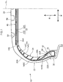
- a cut section which is cut along a tire width direction and a tire radial direction (i.e., a cross-section seen from the direction along the tire circumferential direction), of a run-flat tire (hereinafter called "tire 10") of the present embodiment is shown in Fig. 1 .
- arrow W in the drawings indicates the width direction of the tire 10 (the tire width direction)
- arrow R indicates the radial direction of the tire 10 (the tire radial direction).
- tire width direction here means a direction parallel to the rotational axis of the tire 10.
- the tire radial direction means a direction orthogonal to the rotational axis of the tire 10.
- reference letters CL indicate the equatorial plane of the tire 10 (the tire equatorial plane).
- the side near to the rotational axis of the tire 10 along the tire radial direction is called the “tire radial direction inner side”
- the side that is far from the rotational axis of the tire 10 along the tire radial direction is called the “tire radial direction outer side”.
- the side near to the tire equatorial plane CL along the tire width direction is called the “tire width direction inner side”
- the sides far from the tire equatorial plane CL along the tire width direction are called the "tire width direction outer sides”.
- Fig. 1 shows the tire 10 that is assembled to a rim 30 that is a standard rim, and that is filled to standard air pressure.
- standard rim here refers to the rim prescribed in the 2017 Year Book of JATMA (Japan Automobile Tyre Manufacturer Association, Inc.).
- the aforementioned standard air pressure is the air pressure corresponding to the maximum load capacity in the 2017 Year Book of JATMA (Japan Automobile Tyre Manufacturer Association, Inc.).
- the tire 10 has a pair of bead portions 12, a carcass 14 that straddles bead cores 26 embedded in the bead portions 12 and having end portions that are anchored on the bead cores 26, bead fillers 28 that are embedded in the bead portions 12 and extend from the bead cores 26 along the outer surface of the carcass 14 toward an outer side in the tire radial direction, side reinforcing rubbers 24 that are provided at tire side portions 22 and extend in the tire radial direction along the inner surface of the carcass 14, a belt layer 40 that is provided at the tire radial direction outer side of the carcass 14, and a tread 20 that is provided at the tire radial direction outer side of the belt layer 40. Note that only the bead portion 12 at one side is shown in Fig. 1 .
- the tread 20 that structures the outer peripheral portion of the tire 10 is provided at the tire radial direction outer side of the belt layer 40.
- the tire side portion 22 is structured by a sidewall lower portion 22A that is at the bead portion 12 side, and a sidewall upper portion 22B that is at the tread 20 side, and the tire side portion 22 connects the bead portion 12 and the tread 20.
- the bead cores 26 that are wire bundles are embedded in the pair of bead portions 12, respectively.
- the carcass 14 straddles these bead cores 26.
- Various structures can be employed for the bead cores 26, such as the cross-section thereof is a circular shape or a polygonal shape or the like. Further, for example, a hexagonal shape can be employed as the polygonal shape, but a quadrilateral shape is employed in the present embodiment.
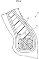
- the bead core 26 is formed by covering one bead wire 26A with resin, being wound plural times and layered. Concretely, first, the row of the first level is formed by the bead wire 26A that is covered by resin being wound without gaps in the tire width direction. Thereafter, similarly, the bead wire 26A that is covered by resin is stacked on the tire radial direction outer side without gaps, and the bead core 26 whose cross-sectional shape is quadrangular is formed. At this time, the covering resins of the bead wire 26A that are adjacent to one another in the tire width direction and radial direction are joined to one another. Due thereto, the bead core 26 in which the bead wire 26A is covered by a covering resin 26B is formed.
- the bead filler 28 which is made of resin and extends from the bead core 26 toward an outer side in the tire radial direction, is embedded in the region, which is surrounded by the carcass 14, of the bead portion 12.
- the carcass 14 is a tire frame member that is structured by two carcass plies 14A, 14B.
- the carcass ply 14A is the carcass ply that is disposed at the tire radial direction outer side at the tire equatorial plane CL
- the carcass ply 14B is the carcass ply that is disposed at the tire radial direction inner side.
- the carcass plies 14A, 14B are each formed by plural cords being covered by a covering rubber.
- the carcass 14 that is formed in this way extends in a toroidal shape from one of the bead cores 26 toward the other bead core 26, and structures the frame of the tire. Further, the end portion sides of the carcass 14 are anchored on the bead cores 26. Concretely, the end portion sides of the carcass 14 are folded over around the bead cores 26 from the tire width direction inner sides to the tire width direction outer sides, and are anchored. Further, the folded-over end portions of the carcass 14 (i.e., end portions 14AE, 14BE) are disposed at the tire side portions 22. The end portion 14AE of the carcass ply 14A is disposed further toward an inner side in the tire radial direction than the end portion 14BE of the carcass ply 14B.
- the present embodiment is structured such that the end portions of the carcass 14 are disposed at the tire side portions 22.
- the present disclosure is not limited to this structure, and may be structured such that, for example, the end portions of the carcass 14 are disposed at the radial direction inner side of the belt layer 40.
- a structure can also be employed in which the end portion sides of the carcass 14 are not folded-over, and are nipped-in by the plural bead cores 26 or are wound onto the bead cores 26.
- the end portions of the carcass 14 being "anchored" on the bead cores 26 includes various types of embodiments such as these.
- the carcass 14 is made to be a radial carcass.
- the material of the carcass 14 is not particularly limited, and rayon, nylon, polyethylene naphthalate (PEN), polyethylene terephthalate (PET), amides, glass fibers, carbon fibers, styrene, or the like can be used.
- Organic fiber cords are preferable from the standpoint of lightening the weight.
- the number of cords within the carcass is in a range of 20 ⁇ 60 cords / 50 mm, but is not limited to this range.
- the belt layer 40 is disposed at an outer side, in the tire radial direction, of the carcass 14. As shown in Fig. 3 , the belt layer 40 is a ring-shaped hoop that is formed by winding a resin-covered cord 42 in a spiral form around the outer peripheral surface of the carcass 14 along the tire circumferential direction.
- the resin-covered cord 42 is structured by covering a reinforcing cord 42C with a covering resin 42S, and, as shown in Fig. 1 , the cross-section thereof is substantially square.
- the tire radial direction inner side surface of the covering resin 42S at the resin-covered cord 42 is structured so as to be joined to the outer peripheral surface of the carcass 14 via rubber or an adhesive. Further, the covering resins 42S, which are adjacent to one another in the tire width direction, of the resin-covered cord 42 are joined integrally by thermal welding or an adhesive or the like. Due thereto, the belt layer 40, which is formed from the reinforcing cord 42C that is covered by the covering resin 42S (i.e., a resin-covered belt layer), is formed.
- the resin-covered cord 42 is structured by covering the one reinforcing cord 42C with the covering resin 42S, but may be structured by covering a plurality of the reinforcing cords 42C with the covering resin 42S.
- the resin material which is used for the covering resin 26B at the bead core 26, the bead filler 28, and the covering resin 42S at the belt layer 40 in the present embodiment, is a thermoplastic elastomer.
- thermoplastic resins thermosetting resins
- general-purpose resins such as (meth)acrylic resins, EVA resins, vinyl chloride resins, fluorine resins, silicone resins and the like
- engineering plastics included super engineering plastics
- vulcanized rubbers are not included among the resin materials here.
- thermoplastic resin is a polymer compound that, as the temperature rises, the material softens and flows, and, when cooled, enters into a state of being relatively hard and having strength.
- the present specification differentiates therebetween in that a polymer compound which, as the temperature rises, the material softens and flows, and, when cooled, enters into a state of being relatively hard and having strength, and which has rubber-like elasticity, is considered to be a thermoplastic elastomer, and a polymer compound which, as the temperature rises, the material softens and flows, and, when cooled, enters into a state of being relatively hard and having strength, and which does not have rubber-like elasticity, is considered to be a thermoplastic resin that is not an elastomer.
- thermoplastic resins include polyolefin thermoplastic elastomers (TPO), polystyrene thermoplastic elastomers (TPS), polyamide thermoplastic elastomers (TPA), polyurethane thermoplastic elastomers (TPU), polyester thermoplastic elastomers (TPC) and dynamically cross-linked thermoplastic elastomers (TPV), as well as polyolefin thermoplastic resins, polystyrene thermoplastic resins, polyamide thermoplastic resins and polyester thermoplastic resins, and the like.
- TPO polyolefin thermoplastic elastomers
- TPS polystyrene thermoplastic elastomers
- TPA polyamide thermoplastic elastomers
- TPU polyurethane thermoplastic elastomers
- TPC polyester thermoplastic elastomers
- TPV dynamically cross-linked thermoplastic elastomers
- thermosetting resin is a polymer compound that, together with a rise in temperature, forms a three-dimensional network structure and hardens, and examples thereof are phenol resins, epoxy resins, melamine resins, urea resins, and the like.
- bead wire 26A of the bead core 26 and the reinforcing cord 42C of the belt layer 40 of the present embodiment are made to be styrene cords.
- These styrene cords have styrene as the main component thereof, and can include minute amounts of various substances such as carbon, manganese, silicon, phosphorous, sulfur, copper, chromium and the like.
- embodiments of the present disclosure are not limited to this, and, as the bead wire 26A at the bead core 26 and the reinforcing cord 42C at the belt layer 40, monofilament cords or cords in which plural filaments are intertwined together can be used instead of styrene cords.
- monofilament cords or cords in which plural filaments are intertwined together can be used instead of styrene cords.
- Various designs can be employed for the intertwined structure as well, and various cross-sectional structures, intertwining pitches, intertwining directions, and distances between adjacent filaments also can be employed.
- cords in which filaments of different materials are twisted together can be employed, and the cross-sectional structure also is not particularly limited, and various intertwined structures of single intertwining, layered intertwining, multiple intertwining and the like can be used.
- the tread 20 is provided at an outer side, in the tire radial direction, of the belt layer 40.
- the tread 20 is the region that contacts the road surface during traveling.
- Plural circumferential direction grooves 50 that extend in the tire circumferential direction are formed in the ground-contacting surface of the tread 20.
- the shapes and the number of the circumferential direction grooves 50 are set appropriately in accordance with the performances that are required of the tire 10, such as the drainability and handling stability and the like.
- the tire side portion 22 extends in the tire radial direction and connects the bead portion 12 and the tread 20, and is structured so as to be able to bear load that is applied to the tire 10 at the time of run-flat traveling.
- the side reinforcing rubber 24 that reinforces the tire side portion 22 is provided at the tire width direction inner side of the carcass 14.
- the side reinforcing rubber 24 is a reinforcing rubber for, in a case in which the internal pressure of the tire 10 decreases due to a puncture or the like, enabling traveling over a predetermined distance in a state of supporting the weight of the vehicle and the passengers.
- the side reinforcing rubber 24 is formed of one type of rubber material.
- the side reinforcing rubber 24 may be formed of plural rubber materials.
- the side reinforcing rubber 24 may contain, in addition thereto, materials such as fillers, short fibers, resin, or the like.
- the side reinforcing rubber 24 may contain a rubber material of a hardness of 70 ⁇ 85 as the rubber material that structures the side reinforcing rubber 24. What is called hardness of the rubber here means the hardness prescribed by JIS K6253 (type A durometer).
- the side reinforcing rubber 24 may contain a rubber material having the property of a loss factor tan ⁇ of 0.10 or less, measured under the conditions of a frequency of 20 Hz, an initial strain of 10%, a dynamic strain of ⁇ 2%, and a temperature of 60°C, by using a viscoelasticity spectrometer (e.g., a spectrometer manufactured by Toyo Seiki Seisaku-sho, Ltd.).
- a viscoelasticity spectrometer e.g., a spectrometer manufactured by Toyo Seiki Seisaku-sho, Ltd.
- the side reinforcing rubber 24 extends along the inner surface of the carcass 14 in the tire radial direction from the bead portion 12 side to the tread 20 side. Further, the side reinforcing rubber 24 is made to be a shape whose thickness decreases from the central portion toward the bead portion 12 side and the tread 20 side, e.g., a substantial crescent shape. Note that what is called the thickness of the side reinforcing rubber 24 here means the length along the normal line of the carcass 14.
- a lower end portion 24B at the bead portion 12 side of the side reinforcing rubber 24 overlaps the bead filler 28 with the carcass 14 nipped therebetween, as seen from the tire width direction. Further, an upper end portion 24A at the tread 20 side of the side reinforcing rubber 24 overlaps the belt layer 40 as seen from the tire radial direction. Concretely, the upper end portion 24A of the side reinforcing rubber 24 overlaps the belt layer 40 with the carcass 14 nipped therebetween. In other words, the upper end portion 24A of the side reinforcing rubber 24 is positioned further toward an inner side in the tire width direction than a tire width direction end portion 40E of the belt layer 40.
- the bead core 26 is formed by the bead wire 26A being covered by the covering resin 26B. Due thereto, the torsional rigidity of the bead core 26 is high, as compared with a case in which the bead wire 26A is covered by rubber. Due thereto, because it is difficult for the bead portion 12 to come-off of the rim 30, the run-flat durability can be improved.
- the belt layer 40 is formed by the reinforcing cord 42C being covered by the covering resin 42S. Due thereto, the out-of-plane bending rigidity of the belt layer 40 is high, as compared with a case in which the reinforcing cord 42C is covered by rubber. Namely, it is difficult for the belt layer 40 to deform from an annular plane, which runs along the tire circumferential direction and the tire width direction, toward the outer sides of this annular plane (e.g., in directions shown by arrows C1, C2 in Fig. 3 ). Due thereto, the tread 20 out-of-plane deforming is suppressed, and therefore, buckling of the tread 20 at the time of run-flat traveling is suppressed.
- the out-of-plane bending rigidity of the belt layer 40 being high, collapsing-in of the tire side portion 22 toward the tire width direction inner side can be suppressed, and therefore, the thickness of the side reinforcing rubber 24 can be made to be small. Due thereto, the effect of reducing the vertical spring, the effect of reducing the rolling resistance, and the effect of improving the handling stability can be improved.
- the in-plane i.e., in the annular plane that runs along the tire circumferential direction and the tire width direction
- shearing rigidity of the belt layer 40 is high. Therefore, for example, at the time of traveling while turning or the like, it is difficult for the tread 20 to deform with respect to shearing force T (see Fig. 3 ) that is applied to the tread 20 in the tire width direction. Due thereto, an intersecting belt layer can be omitted, and therefore, the weight of the tire is light, and the handling stability at the time of traveling on a normal internal pressure is good.
- the ring rigidity of the belt layer 40 is high as compared with a case in which the belt layer 40 is formed by plural cords being lined-up. Due thereto, the tread 20 out-of-plane deforming is further suppressed, and therefore, the buckling suppressing effect of the tread 20 at the time of run-flat traveling can be increased.
- the bead filler 28 is made of resin. Due thereto, the torsional rigidity of the bead filler 28 is high as compared with a case in which the bead filler 28 is formed of rubber. Due thereto, the force by which the bead portion 12, in which the bead filler 28 is embedded, suppresses deformation of the tire side portion 22 is large, and therefore, the thickness of the side reinforcing rubber 24 can be made to be small. If the thickness of the side reinforcing rubber 24 is small, the bending rigidity with respect to force in the tire radial direction of the tire side portion 22 decreases, and therefore, the vertical spring of the tire 10 at the time of traveling on a normal internal pressure can be reduced.
- the volume of the side reinforcing rubber 24 is small and the amount of heat generated at the tire side portion 22 is small, the rolling resistance can be reduced. Moreover, because the weight of the tire 10 is light, the handling stability at the time of traveling on a normal internal pressure improves.
- the bead core 26 is formed by the one bead wire 26A, which is covered by the covering resin 26B, being wound and layered, but embodiments of the present disclosure are not limited to this.
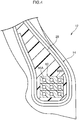
- the bead core may be formed by a wire bundle, in which plural bead wires 60A are covered by a covering resin 60B, being wound and layered.
- the boundary surfaces at the time of layering are fused by thermal welding.
- the number of the bead wires 60A that is contained in one wire bundle is not limited to three, and may be two or may be four or more. Further, the number of wire bundles in each layer in which wire bundles are layered may be one bundle as shown in Fig. 4 , or plural wire bundles may be placed adjacent in the tire width direction such that there are two or more wire bundles.
- bead filler 28 is made of resin in the present embodiment, embodiments of the present disclosure are not limited to this.
- the bead filler 28 may be formed of rubber.
- the belt layer 40 is formed by the resin-covered cord 42, which is substantially square and is formed by the one reinforcing cord 42C being covered by the covering resin 42S, being wound on the outer peripheral surface of the carcass 14.
- the resin-covered cord 42 which is substantially square and is formed by the one reinforcing cord 42C being covered by the covering resin 42S, being wound on the outer peripheral surface of the carcass 14.
- embodiments of the present disclosure are not limited to this.
- the belt layer may be formed by a resin-covered cord 72, whose cross-section is substantially shaped as a parallelogram and that is formed by plural reinforcing cords 72C being covered by the covering resin 42S, being wound on the outer peripheral surface of the carcass 14.
Landscapes
- Engineering & Computer Science (AREA)
- Mechanical Engineering (AREA)
- Tires In General (AREA)
Abstract
Description
- The present disclosure relates to a run-flat tire.
- Japanese Patent Application Laid-Open (
JP-A) No. 2013-95369 - Because a run-flat tire has side reinforcing rubbers as illustrated in aforementioned
JP-A No. 2013-95369 - In view of the above described circumstances, an object of the present disclosure is to suppress coming-off of bead portions from the rim and improve the run-flat durability, in a run-flat tire having side reinforcing rubbers.
- A run-flat tire relating to a first aspect has: a pair of bead cores, each bead core formed by covering a wire with resin; a carcass that straddles the pair of bead cores, and having end portions that are anchored on the bead cores; side reinforcing rubbers that are provided at tire side portions, and that extend in a tire radial direction along an inner surface of the carcass; and a tread that is provided at an outer side, in a tire radial direction, of the carcass.
- In accordance with the run-flat tire relating to the first aspect, due to covering the wire of the each bead core with resin, the torsional rigidity of the bead cores is high as compared with a case in which the wires are covered by rubber. Due thereto, it is difficult for the bead portions to come-off of the rim, and therefore, the run-flat durability can be improved.
- A run-flat tire relating to a second aspect has, at the outer side, in the tire radial direction, of the carcass and at and inner side, in a tire radial direction, of the tread, a belt layer that is formed by covering a cord with resin.
- In accordance with the run-flat tire relating to the second aspect, the belt layer is formed by covering a cord with resin. Due thereto, the out-of-plane bending rigidity of the belt layer is high as compared with a case in which covering the cord with rubber. Namely, it is difficult for the belt layer to deform from an annular plane, which runs along the tire circumferential direction and the tire width direction, toward the outer sides of this annular plane. Due thereto, the tread, which is provided at the outer side, in the tire radial direction, of the belt layer, out-of-plane deforming is suppressed, and therefore, buckling of the tread at the time of run-flat traveling is suppressed.
- Further, as compared with a case in which covering the cord with rubber, the in-plane (i.e., in the annular plane that runs along the tire circumferential direction and tire width direction) shearing rigidity of the belt layer is high. Therefore, for example, at the time of traveling while turning or the like, it is difficult for the tread to deform with respect to shearing force that is applied to the tread in the tire width direction. Due thereto, an intersecting belt layer can be omitted, and therefore, the weight of the tire is light, and the handling stability at the time of traveling on a normal internal pressure is good.
- In a run-flat tire relating to a third aspect, the belt layer is formed by winding the cord in a spiral form along a tire circumferential direction.
- In accordance with the run-flat tire relating to the third aspect, due to the belt layer being formed by winding the cord in a spiral form, the ring rigidity of the belt layer is high as compared with a case in which the belt layer is formed by plural cords being lined-up. Due thereto, the tread out-of-plane deforming is further suppressed, and therefore, the buckling suppressing effect of the tread at the time of run-flat traveling can be increased.
- A run-flat tire relating to a fourth aspect has bead fillers that are made of resin and that extend from the bead cores along an outer surface of the carcass toward a tire radial direction outer side.
- In accordance with the run-flat tire relating to the fourth aspect, due to the bead fillers being formed of resin, the torsional rigidity of the bead fillers is high as compared with a case in which the bead fillers are formed of rubber. Due thereto, the force by which the bead fillers suppress deformation of the tire side portions is large, and therefore, the thickness of the side reinforcing rubbers can be made to be small.
- If the thickness of the side reinforcing rubbers is small, the bending rigidity with respect to force in the tire radial direction of the tire side portions decreases, and therefore, the vertical spring of the tire at the time of traveling on a normal internal pressure can be reduced. Further, because the volume of the tire reinforcing rubbers is small and the amount of heat generated at the tire side portions is small, the rolling resistance can be reduced. Moreover, because the weight of the tire is light, the handling stability at the time of traveling on a normal internal pressure improves.
- In accordance with the present disclosure, the bead portions coming-off of the rim is suppressed, and the run-flat durability can be improved.
-
-
Fig. 1 is a half section showing one side of a cut section in which a run-flat tire relating to an embodiment of the present disclosure is cut along a tire width direction and a tire radial direction in a state of being assembled to a rim. -
Fig. 2 is a partial enlarged sectional view showing a bead core at the run-flat tire relating to the embodiment of the present disclosure. -
Fig. 3 is a perspective view showing a cord layer at the run-flat tire relating to the embodiment of the present disclosure. -
Fig. 4 is a partial enlarged sectional view showing a modified example, in which a bead core is formed by a wire bundle in which plural bead wires are covered by a covering resin, at the run-flat tire relating to the embodiment of the present disclosure. -
Fig. 5 is a half section showing a modified example in which a belt layer is formed by using a resin-covered cord, at which plural reinforcing cords are covered by a covering resin and whose cross- section is substantially shaped as a parallelogram, at the run-flat tire relating to the embodiment of the present disclosure. - One side of a cut section, which is cut along a tire width direction and a tire radial direction (i.e., a cross-section seen from the direction along the tire circumferential direction), of a run-flat tire (hereinafter called "
tire 10") of the present embodiment is shown inFig. 1 . Note that arrow W in the drawings indicates the width direction of the tire 10 (the tire width direction), and arrow R indicates the radial direction of the tire 10 (the tire radial direction). What is called tire width direction here means a direction parallel to the rotational axis of thetire 10. Further, the tire radial direction means a direction orthogonal to the rotational axis of thetire 10. Further, reference letters CL indicate the equatorial plane of the tire 10 (the tire equatorial plane). - Further, in the present embodiment, the side near to the rotational axis of the
tire 10 along the tire radial direction is called the "tire radial direction inner side", and the side that is far from the rotational axis of thetire 10 along the tire radial direction is called the "tire radial direction outer side". On the other hand, the side near to the tire equatorial plane CL along the tire width direction is called the "tire width direction inner side", and the sides far from the tire equatorial plane CL along the tire width direction are called the "tire width direction outer sides". -
Fig. 1 shows thetire 10 that is assembled to arim 30 that is a standard rim, and that is filled to standard air pressure. Note that what is called "standard rim" here refers to the rim prescribed in the 2017 Year Book of JATMA (Japan Automobile Tyre Manufacturer Association, Inc.). Further, the aforementioned standard air pressure is the air pressure corresponding to the maximum load capacity in the 2017 Year Book of JATMA (Japan Automobile Tyre Manufacturer Association, Inc.). - As shown in
Fig. 1 , thetire 10 has a pair ofbead portions 12, acarcass 14 that straddles beadcores 26 embedded in thebead portions 12 and having end portions that are anchored on thebead cores 26,bead fillers 28 that are embedded in thebead portions 12 and extend from thebead cores 26 along the outer surface of thecarcass 14 toward an outer side in the tire radial direction,side reinforcing rubbers 24 that are provided attire side portions 22 and extend in the tire radial direction along the inner surface of thecarcass 14, abelt layer 40 that is provided at the tire radial direction outer side of thecarcass 14, and atread 20 that is provided at the tire radial direction outer side of thebelt layer 40. Note that only thebead portion 12 at one side is shown inFig. 1 . - The
tread 20 that structures the outer peripheral portion of thetire 10 is provided at the tire radial direction outer side of thebelt layer 40. Thetire side portion 22 is structured by a sidewalllower portion 22A that is at thebead portion 12 side, and a sidewallupper portion 22B that is at thetread 20 side, and thetire side portion 22 connects thebead portion 12 and thetread 20. - The
bead cores 26 that are wire bundles are embedded in the pair ofbead portions 12, respectively. Thecarcass 14 straddles thesebead cores 26. Various structures can be employed for thebead cores 26, such as the cross-section thereof is a circular shape or a polygonal shape or the like. Further, for example, a hexagonal shape can be employed as the polygonal shape, but a quadrilateral shape is employed in the present embodiment. - As shown in
Fig. 2 , thebead core 26 is formed by covering onebead wire 26A with resin, being wound plural times and layered. Concretely, first, the row of the first level is formed by thebead wire 26A that is covered by resin being wound without gaps in the tire width direction. Thereafter, similarly, thebead wire 26A that is covered by resin is stacked on the tire radial direction outer side without gaps, and thebead core 26 whose cross-sectional shape is quadrangular is formed. At this time, the covering resins of thebead wire 26A that are adjacent to one another in the tire width direction and radial direction are joined to one another. Due thereto, thebead core 26 in which thebead wire 26A is covered by a coveringresin 26B is formed. - As shown in
Fig. 1 , thebead filler 28, which is made of resin and extends from thebead core 26 toward an outer side in the tire radial direction, is embedded in the region, which is surrounded by thecarcass 14, of thebead portion 12. - The
carcass 14 is a tire frame member that is structured by two carcass plies 14A, 14B. The carcass ply 14A is the carcass ply that is disposed at the tire radial direction outer side at the tire equatorial plane CL, and thecarcass ply 14B is the carcass ply that is disposed at the tire radial direction inner side. The carcass plies 14A, 14B are each formed by plural cords being covered by a covering rubber. - The
carcass 14 that is formed in this way extends in a toroidal shape from one of thebead cores 26 toward theother bead core 26, and structures the frame of the tire. Further, the end portion sides of thecarcass 14 are anchored on thebead cores 26. Concretely, the end portion sides of thecarcass 14 are folded over around thebead cores 26 from the tire width direction inner sides to the tire width direction outer sides, and are anchored. Further, the folded-over end portions of the carcass 14 (i.e., end portions 14AE, 14BE) are disposed at thetire side portions 22. The end portion 14AE of the carcass ply 14A is disposed further toward an inner side in the tire radial direction than the end portion 14BE of the carcass ply 14B. - Note that the present embodiment is structured such that the end portions of the
carcass 14 are disposed at thetire side portions 22. However, the present disclosure is not limited to this structure, and may be structured such that, for example, the end portions of thecarcass 14 are disposed at the radial direction inner side of thebelt layer 40. Further, a structure can also be employed in which the end portion sides of thecarcass 14 are not folded-over, and are nipped-in by theplural bead cores 26 or are wound onto thebead cores 26. In the present specification, the end portions of thecarcass 14 being "anchored" on thebead cores 26 includes various types of embodiments such as these. - Note that, in the present embodiment, the
carcass 14 is made to be a radial carcass. Further, the material of thecarcass 14 is not particularly limited, and rayon, nylon, polyethylene naphthalate (PEN), polyethylene terephthalate (PET), amides, glass fibers, carbon fibers, styrene, or the like can be used. Organic fiber cords are preferable from the standpoint of lightening the weight. Further, the number of cords within the carcass is in a range of 20 ∼ 60 cords / 50 mm, but is not limited to this range. - The
belt layer 40 is disposed at an outer side, in the tire radial direction, of thecarcass 14. As shown inFig. 3 , thebelt layer 40 is a ring-shaped hoop that is formed by winding a resin-coveredcord 42 in a spiral form around the outer peripheral surface of thecarcass 14 along the tire circumferential direction. - The resin-covered
cord 42 is structured by covering a reinforcingcord 42C with a coveringresin 42S, and, as shown inFig. 1 , the cross-section thereof is substantially square. The tire radial direction inner side surface of the coveringresin 42S at the resin-coveredcord 42 is structured so as to be joined to the outer peripheral surface of thecarcass 14 via rubber or an adhesive. Further, the covering resins 42S, which are adjacent to one another in the tire width direction, of the resin-coveredcord 42 are joined integrally by thermal welding or an adhesive or the like. Due thereto, thebelt layer 40, which is formed from the reinforcingcord 42C that is covered by the coveringresin 42S (i.e., a resin-covered belt layer), is formed. - Note that, in the present embodiment, the resin-covered
cord 42 is structured by covering the one reinforcingcord 42C with the coveringresin 42S, but may be structured by covering a plurality of the reinforcingcords 42C with the coveringresin 42S. - The resin material, which is used for the covering
resin 26B at thebead core 26, thebead filler 28, and the coveringresin 42S at thebelt layer 40 in the present embodiment, is a thermoplastic elastomer. However, embodiments of the present disclosure are not limited to this, and, for example, thermoplastic resins, thermosetting resins, general-purpose resins such as (meth)acrylic resins, EVA resins, vinyl chloride resins, fluorine resins, silicone resins and the like, and, in addition thereto, engineering plastics (included super engineering plastics) and the like can be used as the resin material. Note that vulcanized rubbers are not included among the resin materials here. - A thermoplastic resin (including thermoplastic elastomers) is a polymer compound that, as the temperature rises, the material softens and flows, and, when cooled, enters into a state of being relatively hard and having strength. The present specification differentiates therebetween in that a polymer compound which, as the temperature rises, the material softens and flows, and, when cooled, enters into a state of being relatively hard and having strength, and which has rubber-like elasticity, is considered to be a thermoplastic elastomer, and a polymer compound which, as the temperature rises, the material softens and flows, and, when cooled, enters into a state of being relatively hard and having strength, and which does not have rubber-like elasticity, is considered to be a thermoplastic resin that is not an elastomer.
- Examples of thermoplastic resins (including thermoplastic elastomers) include polyolefin thermoplastic elastomers (TPO), polystyrene thermoplastic elastomers (TPS), polyamide thermoplastic elastomers (TPA), polyurethane thermoplastic elastomers (TPU), polyester thermoplastic elastomers (TPC) and dynamically cross-linked thermoplastic elastomers (TPV), as well as polyolefin thermoplastic resins, polystyrene thermoplastic resins, polyamide thermoplastic resins and polyester thermoplastic resins, and the like.
- A thermosetting resin is a polymer compound that, together with a rise in temperature, forms a three-dimensional network structure and hardens, and examples thereof are phenol resins, epoxy resins, melamine resins, urea resins, and the like.
- Further, the
bead wire 26A of thebead core 26 and the reinforcingcord 42C of thebelt layer 40 of the present embodiment are made to be styrene cords. These styrene cords have styrene as the main component thereof, and can include minute amounts of various substances such as carbon, manganese, silicon, phosphorous, sulfur, copper, chromium and the like. - Note that embodiments of the present disclosure are not limited to this, and, as the
bead wire 26A at thebead core 26 and the reinforcingcord 42C at thebelt layer 40, monofilament cords or cords in which plural filaments are intertwined together can be used instead of styrene cords. Various designs can be employed for the intertwined structure as well, and various cross-sectional structures, intertwining pitches, intertwining directions, and distances between adjacent filaments also can be employed. Moreover, cords in which filaments of different materials are twisted together can be employed, and the cross-sectional structure also is not particularly limited, and various intertwined structures of single intertwining, layered intertwining, multiple intertwining and the like can be used. - The
tread 20 is provided at an outer side, in the tire radial direction, of thebelt layer 40. Thetread 20 is the region that contacts the road surface during traveling. Pluralcircumferential direction grooves 50 that extend in the tire circumferential direction are formed in the ground-contacting surface of thetread 20. The shapes and the number of thecircumferential direction grooves 50 are set appropriately in accordance with the performances that are required of thetire 10, such as the drainability and handling stability and the like. - The
tire side portion 22 extends in the tire radial direction and connects thebead portion 12 and thetread 20, and is structured so as to be able to bear load that is applied to thetire 10 at the time of run-flat traveling. At thistire side portion 22, theside reinforcing rubber 24 that reinforces thetire side portion 22 is provided at the tire width direction inner side of thecarcass 14. Theside reinforcing rubber 24 is a reinforcing rubber for, in a case in which the internal pressure of thetire 10 decreases due to a puncture or the like, enabling traveling over a predetermined distance in a state of supporting the weight of the vehicle and the passengers. - In the present embodiment, the
side reinforcing rubber 24 is formed of one type of rubber material. However, embodiments of the present disclosure are not limited to this, and theside reinforcing rubber 24 may be formed of plural rubber materials. Further, provided that a rubber material is the main component thereof, theside reinforcing rubber 24 may contain, in addition thereto, materials such as fillers, short fibers, resin, or the like. Moreover, in order to improve the durability at the time of run-flat traveling, theside reinforcing rubber 24 may contain a rubber material of a hardness of 70 ∼ 85 as the rubber material that structures theside reinforcing rubber 24. What is called hardness of the rubber here means the hardness prescribed by JIS K6253 (type A durometer). Moreover, theside reinforcing rubber 24 may contain a rubber material having the property of a loss factor tan δ of 0.10 or less, measured under the conditions of a frequency of 20 Hz, an initial strain of 10%, a dynamic strain of ±2%, and a temperature of 60°C, by using a viscoelasticity spectrometer (e.g., a spectrometer manufactured by Toyo Seiki Seisaku-sho, Ltd.). - The
side reinforcing rubber 24 extends along the inner surface of thecarcass 14 in the tire radial direction from thebead portion 12 side to thetread 20 side. Further, theside reinforcing rubber 24 is made to be a shape whose thickness decreases from the central portion toward thebead portion 12 side and thetread 20 side, e.g., a substantial crescent shape. Note that what is called the thickness of theside reinforcing rubber 24 here means the length along the normal line of thecarcass 14. - A
lower end portion 24B at thebead portion 12 side of theside reinforcing rubber 24 overlaps thebead filler 28 with thecarcass 14 nipped therebetween, as seen from the tire width direction. Further, anupper end portion 24A at thetread 20 side of theside reinforcing rubber 24 overlaps thebelt layer 40 as seen from the tire radial direction. Concretely, theupper end portion 24A of theside reinforcing rubber 24 overlaps thebelt layer 40 with thecarcass 14 nipped therebetween. In other words, theupper end portion 24A of theside reinforcing rubber 24 is positioned further toward an inner side in the tire width direction than a tire widthdirection end portion 40E of thebelt layer 40. - In the
tire 10 relating to the present embodiment, thebead core 26 is formed by thebead wire 26A being covered by the coveringresin 26B. Due thereto, the torsional rigidity of thebead core 26 is high, as compared with a case in which thebead wire 26A is covered by rubber. Due thereto, because it is difficult for thebead portion 12 to come-off of therim 30, the run-flat durability can be improved. - Further in the
tire 10 relating to the present embodiment, thebelt layer 40 is formed by the reinforcingcord 42C being covered by the coveringresin 42S. Due thereto, the out-of-plane bending rigidity of thebelt layer 40 is high, as compared with a case in which the reinforcingcord 42C is covered by rubber. Namely, it is difficult for thebelt layer 40 to deform from an annular plane, which runs along the tire circumferential direction and the tire width direction, toward the outer sides of this annular plane (e.g., in directions shown by arrows C1, C2 inFig. 3 ). Due thereto, thetread 20 out-of-plane deforming is suppressed, and therefore, buckling of thetread 20 at the time of run-flat traveling is suppressed. - Moreover, due to the out-of-plane bending rigidity of the
belt layer 40 being high, collapsing-in of thetire side portion 22 toward the tire width direction inner side can be suppressed, and therefore, the thickness of theside reinforcing rubber 24 can be made to be small. Due thereto, the effect of reducing the vertical spring, the effect of reducing the rolling resistance, and the effect of improving the handling stability can be improved. - Further, as compared with a case in which the reinforcing
cord 42C is covered by a rubber, the in-plane (i.e., in the annular plane that runs along the tire circumferential direction and the tire width direction) shearing rigidity of thebelt layer 40 is high. Therefore, for example, at the time of traveling while turning or the like, it is difficult for thetread 20 to deform with respect to shearing force T (seeFig. 3 ) that is applied to thetread 20 in the tire width direction. Due thereto, an intersecting belt layer can be omitted, and therefore, the weight of the tire is light, and the handling stability at the time of traveling on a normal internal pressure is good. - Further, in the
tire 10 relating to the present embodiment, due to thebelt layer 40 being formed by the resin-covered cord 42 (and the reinforcingcord 42C) being wound in a spiral form, the ring rigidity of thebelt layer 40 is high as compared with a case in which thebelt layer 40 is formed by plural cords being lined-up. Due thereto, thetread 20 out-of-plane deforming is further suppressed, and therefore, the buckling suppressing effect of thetread 20 at the time of run-flat traveling can be increased. - At the
tire 10 relating to the present embodiment, thebead filler 28 is made of resin. Due thereto, the torsional rigidity of thebead filler 28 is high as compared with a case in which thebead filler 28 is formed of rubber. Due thereto, the force by which thebead portion 12, in which thebead filler 28 is embedded, suppresses deformation of thetire side portion 22 is large, and therefore, the thickness of theside reinforcing rubber 24 can be made to be small.
If the thickness of theside reinforcing rubber 24 is small, the bending rigidity with respect to force in the tire radial direction of thetire side portion 22 decreases, and therefore, the vertical spring of thetire 10 at the time of traveling on a normal internal pressure can be reduced. Further, because the volume of theside reinforcing rubber 24 is small and the amount of heat generated at thetire side portion 22 is small, the rolling resistance can be reduced. Moreover, because the weight of thetire 10 is light, the handling stability at the time of traveling on a normal internal pressure improves. - Note that, in the present embodiment, the
bead core 26 is formed by the onebead wire 26A, which is covered by the coveringresin 26B, being wound and layered, but embodiments of the present disclosure are not limited to this. For example, as at thebead core 60 shown inFig. 4 , the bead core may be formed by a wire bundle, in whichplural bead wires 60A are covered by a coveringresin 60B, being wound and layered. - In this case, the boundary surfaces at the time of layering are fused by thermal welding. The number of the
bead wires 60A that is contained in one wire bundle is not limited to three, and may be two or may be four or more. Further, the number of wire bundles in each layer in which wire bundles are layered may be one bundle as shown inFig. 4 , or plural wire bundles may be placed adjacent in the tire width direction such that there are two or more wire bundles. - Further, although the
bead filler 28 is made of resin in the present embodiment, embodiments of the present disclosure are not limited to this. For example, thebead filler 28 may be formed of rubber. - Even if a covering rubber is used instead of the covering
resin 26B, or thebead filler 28 is formed of rubber, due to thebelt layer 40 being formed by the reinforcingcord 42C being covered by the coveringresin 42S, buckling of thetread 20 at the time of run-flat traveling can be suppressed. - Further, in the present embodiment, the
belt layer 40 is formed by the resin-coveredcord 42, which is substantially square and is formed by the one reinforcingcord 42C being covered by the coveringresin 42S, being wound on the outer peripheral surface of thecarcass 14. However, embodiments of the present disclosure are not limited to this. - For example, as in a
belt layer 70 shown inFig. 5 , the belt layer may be formed by a resin-coveredcord 72, whose cross-section is substantially shaped as a parallelogram and that is formed by plural reinforcingcords 72C being covered by the coveringresin 42S, being wound on the outer peripheral surface of thecarcass 14. - The disclosure of Japanese Patent Application No.
2017-119809 filed on June 19, 2017
Claims (4)
- A run-flat tire, comprising:a pair of bead cores, each bead core formed by covering a wire with resin;a carcass that straddles the pair of bead cores, and having end portions that are anchored on the bead cores;side reinforcing rubbers that are provided at tire side portions, and that extend in a tire radial direction along an inner surface of the carcass; anda tread that is provided at an outer side, in a tire radial direction, of the carcass.
- The run-flat tire of claim 1, comprising, at the outer side, in the tire radial direction, of the carcass and at an inner side, in a tire radial direction, of the tread, a belt layer that is formed by covering a cord with resin.
- The run-flat tire of claim 2, wherein the belt layer is formed by winding the cord in a spiral form along a tire circumferential direction.
- The run-flat tire of any one of claim 1 through claim 3, comprising bead fillers that are made of resin and that extend from the bead cores along an outer surface of the carcass toward a tire radial direction outer side.
Applications Claiming Priority (2)
| Application Number | Priority Date | Filing Date | Title |
|---|---|---|---|
| JP2017119809A JP6781671B2 (en) | 2017-06-19 | 2017-06-19 | Run flat tire |
| PCT/JP2018/021262 WO2018235571A1 (en) | 2017-06-19 | 2018-06-01 | Run flat tire |
Publications (3)
| Publication Number | Publication Date |
|---|---|
| EP3643539A1 true EP3643539A1 (en) | 2020-04-29 |
| EP3643539A4 EP3643539A4 (en) | 2021-03-24 |
| EP3643539B1 EP3643539B1 (en) | 2023-05-10 |
Family
ID=64737540
Family Applications (1)
| Application Number | Title | Priority Date | Filing Date |
|---|---|---|---|
| EP18821545.3A Active EP3643539B1 (en) | 2017-06-19 | 2018-06-01 | Run-flat tire |
Country Status (5)
| Country | Link |
|---|---|
| US (1) | US20200130428A1 (en) |
| EP (1) | EP3643539B1 (en) |
| JP (1) | JP6781671B2 (en) |
| CN (1) | CN110770048A (en) |
| WO (1) | WO2018235571A1 (en) |
Families Citing this family (2)
| Publication number | Priority date | Publication date | Assignee | Title |
|---|---|---|---|---|
| JP2020203574A (en) * | 2019-06-17 | 2020-12-24 | 株式会社ブリヂストン | Run-flat tire |
| CN119910937B (en) * | 2025-02-13 | 2025-11-28 | 肇庆骏鸿实业有限公司 | A run-flat tire with improved high-speed performance and its tread processing equipment |
Family Cites Families (15)
| Publication number | Priority date | Publication date | Assignee | Title |
|---|---|---|---|---|
| US5871600A (en) * | 1997-05-29 | 1999-02-16 | The Goodyear Tire & Rubber Company | Runflat tire with different modulus or elongation carcass cords |
| JP2010116027A (en) * | 2008-11-12 | 2010-05-27 | Bridgestone Corp | Pneumatic tire |
| JP2010201959A (en) * | 2009-02-27 | 2010-09-16 | Bridgestone Corp | Pneumatic tire |
| WO2011030431A1 (en) * | 2009-09-10 | 2011-03-17 | 株式会社ブリヂストン | Run-flat tire |
| JP2013063743A (en) * | 2011-09-20 | 2013-04-11 | Bridgestone Corp | Rubber composite and pneumatic tire |
| JP5938873B2 (en) | 2011-11-04 | 2016-06-22 | 横浜ゴム株式会社 | Pneumatic tire |
| US9902121B2 (en) * | 2011-12-12 | 2018-02-27 | Bridgestone Corporation | Tire |
| JP6347978B2 (en) * | 2014-04-14 | 2018-06-27 | 株式会社ブリヂストン | Run flat tire |
| JP6452337B2 (en) * | 2014-07-23 | 2019-01-16 | 株式会社ブリヂストン | tire |
| EP3176002B1 (en) * | 2014-07-30 | 2018-09-12 | Bridgestone Corporation | Tire |
| JP6266498B2 (en) * | 2014-11-26 | 2018-01-24 | 株式会社ブリヂストン | tire |
| CN107709040B (en) * | 2015-06-29 | 2019-11-22 | 株式会社普利司通 | Tires and tire manufacturing methods |
| US20180297410A1 (en) * | 2015-10-07 | 2018-10-18 | Bridgestone Corporation | Tire |
| JP6639201B2 (en) * | 2015-11-25 | 2020-02-05 | 株式会社ブリヂストン | tire |
| JP6894673B2 (en) | 2015-12-24 | 2021-06-30 | 日東電工株式会社 | Single-sided adhesive adhesive sheet |
-
2017
- 2017-06-19 JP JP2017119809A patent/JP6781671B2/en active Active
-
2018
- 2018-06-01 EP EP18821545.3A patent/EP3643539B1/en active Active
- 2018-06-01 US US16/623,765 patent/US20200130428A1/en not_active Abandoned
- 2018-06-01 CN CN201880040697.1A patent/CN110770048A/en active Pending
- 2018-06-01 WO PCT/JP2018/021262 patent/WO2018235571A1/en not_active Ceased
Also Published As
| Publication number | Publication date |
|---|---|
| US20200130428A1 (en) | 2020-04-30 |
| EP3643539A4 (en) | 2021-03-24 |
| EP3643539B1 (en) | 2023-05-10 |
| JP6781671B2 (en) | 2020-11-04 |
| WO2018235571A1 (en) | 2018-12-27 |
| JP2019001404A (en) | 2019-01-10 |
| CN110770048A (en) | 2020-02-07 |
Similar Documents
| Publication | Publication Date | Title |
|---|---|---|
| EP3643539B1 (en) | Run-flat tire | |
| EP3643537A1 (en) | Run-flat tire | |
| EP3795380A1 (en) | Pneumatic tire | |
| EP3812169A1 (en) | Tire | |
| EP3643538A1 (en) | Run-flat tire | |
| JP2019217899A (en) | Pneumatic tire | |
| EP3812167A1 (en) | Resin-covered cords and pneumatic tire | |
| WO2019220889A1 (en) | Pneumatic tire | |
| JP2019217822A (en) | Pneumatic tire | |
| JP6909715B2 (en) | Run flat tire | |
| JP2019217819A (en) | Pneumatic tire | |
| JP2019217928A (en) | Pneumatic tire | |
| WO2019230812A1 (en) | Pneumatic tire | |
| JPWO2019244741A1 (en) | Pneumatic tires | |
| JP2021154753A (en) | Pneumatic tire | |
| WO2019117287A1 (en) | Support and tire-rim assembly | |
| JPWO2019244740A1 (en) | Pneumatic tires | |
| WO2019230811A1 (en) | Pneumatic tire | |
| JP2019217852A (en) | Pneumatic tire | |
| JP2019217851A (en) | Pneumatic tire |
Legal Events
| Date | Code | Title | Description |
|---|---|---|---|
| STAA | Information on the status of an ep patent application or granted ep patent |
Free format text: STATUS: THE INTERNATIONAL PUBLICATION HAS BEEN MADE |
|
| PUAI | Public reference made under article 153(3) epc to a published international application that has entered the european phase |
Free format text: ORIGINAL CODE: 0009012 |
|
| STAA | Information on the status of an ep patent application or granted ep patent |
Free format text: STATUS: REQUEST FOR EXAMINATION WAS MADE |
|
| 17P | Request for examination filed |
Effective date: 20200117 |
|
| AK | Designated contracting states |
Kind code of ref document: A1 Designated state(s): AL AT BE BG CH CY CZ DE DK EE ES FI FR GB GR HR HU IE IS IT LI LT LU LV MC MK MT NL NO PL PT RO RS SE SI SK SM TR |
|
| AX | Request for extension of the european patent |
Extension state: BA ME |
|
| DAV | Request for validation of the european patent (deleted) | ||
| DAX | Request for extension of the european patent (deleted) | ||
| A4 | Supplementary search report drawn up and despatched |
Effective date: 20210223 |
|
| RIC1 | Information provided on ipc code assigned before grant |
Ipc: B60C 17/00 20060101AFI20210217BHEP Ipc: B60C 15/04 20060101ALI20210217BHEP Ipc: B60C 1/00 20060101ALI20210217BHEP Ipc: B29D 30/16 20060101ALI20210217BHEP Ipc: B60C 15/05 20060101ALI20210217BHEP Ipc: B60C 15/00 20060101ALI20210217BHEP |
|
| STAA | Information on the status of an ep patent application or granted ep patent |
Free format text: STATUS: EXAMINATION IS IN PROGRESS |
|
| 17Q | First examination report despatched |
Effective date: 20220216 |
|
| REG | Reference to a national code |
Ref country code: DE Ref legal event code: R079 Ref document number: 602018049732 Country of ref document: DE Free format text: PREVIOUS MAIN CLASS: B60C0017000000 Ipc: B29D0030300000 |
|
| RIC1 | Information provided on ipc code assigned before grant |
Ipc: B60C 15/05 20060101ALI20221005BHEP Ipc: B60C 17/00 20060101ALI20221005BHEP Ipc: B60C 15/00 20060101ALI20221005BHEP Ipc: B60C 15/04 20060101ALI20221005BHEP Ipc: B29D 30/72 20060101ALI20221005BHEP Ipc: B29D 30/06 20060101ALI20221005BHEP Ipc: B29D 30/70 20060101ALI20221005BHEP Ipc: B29D 30/30 20060101AFI20221005BHEP |
|
| GRAP | Despatch of communication of intention to grant a patent |
Free format text: ORIGINAL CODE: EPIDOSNIGR1 |
|
| STAA | Information on the status of an ep patent application or granted ep patent |
Free format text: STATUS: GRANT OF PATENT IS INTENDED |
|
| INTG | Intention to grant announced |
Effective date: 20221130 |
|
| GRAS | Grant fee paid |
Free format text: ORIGINAL CODE: EPIDOSNIGR3 |
|
| GRAA | (expected) grant |
Free format text: ORIGINAL CODE: 0009210 |
|
| STAA | Information on the status of an ep patent application or granted ep patent |
Free format text: STATUS: THE PATENT HAS BEEN GRANTED |
|
| AK | Designated contracting states |
Kind code of ref document: B1 Designated state(s): AL AT BE BG CH CY CZ DE DK EE ES FI FR GB GR HR HU IE IS IT LI LT LU LV MC MK MT NL NO PL PT RO RS SE SI SK SM TR |
|
| REG | Reference to a national code |
Ref country code: GB Ref legal event code: FG4D |
|
| REG | Reference to a national code |
Ref country code: AT Ref legal event code: REF Ref document number: 1566292 Country of ref document: AT Kind code of ref document: T Effective date: 20230515 Ref country code: CH Ref legal event code: EP |
|
| REG | Reference to a national code |
Ref country code: DE Ref legal event code: R096 Ref document number: 602018049732 Country of ref document: DE |
|
| REG | Reference to a national code |
Ref country code: IE Ref legal event code: FG4D |
|
| REG | Reference to a national code |
Ref country code: LT Ref legal event code: MG9D |
|
| REG | Reference to a national code |
Ref country code: NL Ref legal event code: MP Effective date: 20230510 |
|
| REG | Reference to a national code |
Ref country code: AT Ref legal event code: MK05 Ref document number: 1566292 Country of ref document: AT Kind code of ref document: T Effective date: 20230510 |
|
| PG25 | Lapsed in a contracting state [announced via postgrant information from national office to epo] |
Ref country code: SE Free format text: LAPSE BECAUSE OF FAILURE TO SUBMIT A TRANSLATION OF THE DESCRIPTION OR TO PAY THE FEE WITHIN THE PRESCRIBED TIME-LIMIT Effective date: 20230510 Ref country code: PT Free format text: LAPSE BECAUSE OF FAILURE TO SUBMIT A TRANSLATION OF THE DESCRIPTION OR TO PAY THE FEE WITHIN THE PRESCRIBED TIME-LIMIT Effective date: 20230911 Ref country code: NO Free format text: LAPSE BECAUSE OF FAILURE TO SUBMIT A TRANSLATION OF THE DESCRIPTION OR TO PAY THE FEE WITHIN THE PRESCRIBED TIME-LIMIT Effective date: 20230810 Ref country code: NL Free format text: LAPSE BECAUSE OF FAILURE TO SUBMIT A TRANSLATION OF THE DESCRIPTION OR TO PAY THE FEE WITHIN THE PRESCRIBED TIME-LIMIT Effective date: 20230510 Ref country code: ES Free format text: LAPSE BECAUSE OF FAILURE TO SUBMIT A TRANSLATION OF THE DESCRIPTION OR TO PAY THE FEE WITHIN THE PRESCRIBED TIME-LIMIT Effective date: 20230510 Ref country code: AT Free format text: LAPSE BECAUSE OF FAILURE TO SUBMIT A TRANSLATION OF THE DESCRIPTION OR TO PAY THE FEE WITHIN THE PRESCRIBED TIME-LIMIT Effective date: 20230510 |
|
| PG25 | Lapsed in a contracting state [announced via postgrant information from national office to epo] |
Ref country code: RS Free format text: LAPSE BECAUSE OF FAILURE TO SUBMIT A TRANSLATION OF THE DESCRIPTION OR TO PAY THE FEE WITHIN THE PRESCRIBED TIME-LIMIT Effective date: 20230510 Ref country code: PL Free format text: LAPSE BECAUSE OF FAILURE TO SUBMIT A TRANSLATION OF THE DESCRIPTION OR TO PAY THE FEE WITHIN THE PRESCRIBED TIME-LIMIT Effective date: 20230510 Ref country code: LV Free format text: LAPSE BECAUSE OF FAILURE TO SUBMIT A TRANSLATION OF THE DESCRIPTION OR TO PAY THE FEE WITHIN THE PRESCRIBED TIME-LIMIT Effective date: 20230510 Ref country code: LT Free format text: LAPSE BECAUSE OF FAILURE TO SUBMIT A TRANSLATION OF THE DESCRIPTION OR TO PAY THE FEE WITHIN THE PRESCRIBED TIME-LIMIT Effective date: 20230510 Ref country code: IS Free format text: LAPSE BECAUSE OF FAILURE TO SUBMIT A TRANSLATION OF THE DESCRIPTION OR TO PAY THE FEE WITHIN THE PRESCRIBED TIME-LIMIT Effective date: 20230910 Ref country code: HR Free format text: LAPSE BECAUSE OF FAILURE TO SUBMIT A TRANSLATION OF THE DESCRIPTION OR TO PAY THE FEE WITHIN THE PRESCRIBED TIME-LIMIT Effective date: 20230510 Ref country code: GR Free format text: LAPSE BECAUSE OF FAILURE TO SUBMIT A TRANSLATION OF THE DESCRIPTION OR TO PAY THE FEE WITHIN THE PRESCRIBED TIME-LIMIT Effective date: 20230811 |
|
| PG25 | Lapsed in a contracting state [announced via postgrant information from national office to epo] |
Ref country code: FI Free format text: LAPSE BECAUSE OF FAILURE TO SUBMIT A TRANSLATION OF THE DESCRIPTION OR TO PAY THE FEE WITHIN THE PRESCRIBED TIME-LIMIT Effective date: 20230510 |
|
| PG25 | Lapsed in a contracting state [announced via postgrant information from national office to epo] |
Ref country code: SK Free format text: LAPSE BECAUSE OF FAILURE TO SUBMIT A TRANSLATION OF THE DESCRIPTION OR TO PAY THE FEE WITHIN THE PRESCRIBED TIME-LIMIT Effective date: 20230510 |
|
| PG25 | Lapsed in a contracting state [announced via postgrant information from national office to epo] |
Ref country code: SM Free format text: LAPSE BECAUSE OF FAILURE TO SUBMIT A TRANSLATION OF THE DESCRIPTION OR TO PAY THE FEE WITHIN THE PRESCRIBED TIME-LIMIT Effective date: 20230510 Ref country code: SK Free format text: LAPSE BECAUSE OF FAILURE TO SUBMIT A TRANSLATION OF THE DESCRIPTION OR TO PAY THE FEE WITHIN THE PRESCRIBED TIME-LIMIT Effective date: 20230510 Ref country code: RO Free format text: LAPSE BECAUSE OF FAILURE TO SUBMIT A TRANSLATION OF THE DESCRIPTION OR TO PAY THE FEE WITHIN THE PRESCRIBED TIME-LIMIT Effective date: 20230510 Ref country code: EE Free format text: LAPSE BECAUSE OF FAILURE TO SUBMIT A TRANSLATION OF THE DESCRIPTION OR TO PAY THE FEE WITHIN THE PRESCRIBED TIME-LIMIT Effective date: 20230510 Ref country code: DK Free format text: LAPSE BECAUSE OF FAILURE TO SUBMIT A TRANSLATION OF THE DESCRIPTION OR TO PAY THE FEE WITHIN THE PRESCRIBED TIME-LIMIT Effective date: 20230510 Ref country code: CZ Free format text: LAPSE BECAUSE OF FAILURE TO SUBMIT A TRANSLATION OF THE DESCRIPTION OR TO PAY THE FEE WITHIN THE PRESCRIBED TIME-LIMIT Effective date: 20230510 |
|
| REG | Reference to a national code |
Ref country code: CH Ref legal event code: PL |
|
| REG | Reference to a national code |
Ref country code: DE Ref legal event code: R097 Ref document number: 602018049732 Country of ref document: DE |
|
| REG | Reference to a national code |
Ref country code: BE Ref legal event code: MM Effective date: 20230630 |
|
| PG25 | Lapsed in a contracting state [announced via postgrant information from national office to epo] |
Ref country code: MC Free format text: LAPSE BECAUSE OF FAILURE TO SUBMIT A TRANSLATION OF THE DESCRIPTION OR TO PAY THE FEE WITHIN THE PRESCRIBED TIME-LIMIT Effective date: 20230510 |
|
| PG25 | Lapsed in a contracting state [announced via postgrant information from national office to epo] |
Ref country code: MC Free format text: LAPSE BECAUSE OF FAILURE TO SUBMIT A TRANSLATION OF THE DESCRIPTION OR TO PAY THE FEE WITHIN THE PRESCRIBED TIME-LIMIT Effective date: 20230510 |
|
| PG25 | Lapsed in a contracting state [announced via postgrant information from national office to epo] |
Ref country code: LU Free format text: LAPSE BECAUSE OF NON-PAYMENT OF DUE FEES Effective date: 20230601 |
|
| PLBE | No opposition filed within time limit |
Free format text: ORIGINAL CODE: 0009261 |
|
| STAA | Information on the status of an ep patent application or granted ep patent |
Free format text: STATUS: NO OPPOSITION FILED WITHIN TIME LIMIT |
|
| REG | Reference to a national code |
Ref country code: IE Ref legal event code: MM4A |
|
| PG25 | Lapsed in a contracting state [announced via postgrant information from national office to epo] |
Ref country code: LU Free format text: LAPSE BECAUSE OF NON-PAYMENT OF DUE FEES Effective date: 20230601 |
|
| PG25 | Lapsed in a contracting state [announced via postgrant information from national office to epo] |
Ref country code: IE Free format text: LAPSE BECAUSE OF NON-PAYMENT OF DUE FEES Effective date: 20230601 |
|
| 26N | No opposition filed |
Effective date: 20240213 |
|
| GBPC | Gb: european patent ceased through non-payment of renewal fee |
Effective date: 20230810 |
|
| PG25 | Lapsed in a contracting state [announced via postgrant information from national office to epo] |
Ref country code: IE Free format text: LAPSE BECAUSE OF NON-PAYMENT OF DUE FEES Effective date: 20230601 Ref country code: CH Free format text: LAPSE BECAUSE OF NON-PAYMENT OF DUE FEES Effective date: 20230630 |
|
| PG25 | Lapsed in a contracting state [announced via postgrant information from national office to epo] |
Ref country code: SI Free format text: LAPSE BECAUSE OF FAILURE TO SUBMIT A TRANSLATION OF THE DESCRIPTION OR TO PAY THE FEE WITHIN THE PRESCRIBED TIME-LIMIT Effective date: 20230510 |
|
| PG25 | Lapsed in a contracting state [announced via postgrant information from national office to epo] |
Ref country code: SI Free format text: LAPSE BECAUSE OF FAILURE TO SUBMIT A TRANSLATION OF THE DESCRIPTION OR TO PAY THE FEE WITHIN THE PRESCRIBED TIME-LIMIT Effective date: 20230510 Ref country code: IT Free format text: LAPSE BECAUSE OF FAILURE TO SUBMIT A TRANSLATION OF THE DESCRIPTION OR TO PAY THE FEE WITHIN THE PRESCRIBED TIME-LIMIT Effective date: 20230510 Ref country code: BE Free format text: LAPSE BECAUSE OF NON-PAYMENT OF DUE FEES Effective date: 20230630 |
|
| PG25 | Lapsed in a contracting state [announced via postgrant information from national office to epo] |
Ref country code: GB Free format text: LAPSE BECAUSE OF NON-PAYMENT OF DUE FEES Effective date: 20230810 |
|
| PG25 | Lapsed in a contracting state [announced via postgrant information from national office to epo] |
Ref country code: GB Free format text: LAPSE BECAUSE OF NON-PAYMENT OF DUE FEES Effective date: 20230810 |
|
| PG25 | Lapsed in a contracting state [announced via postgrant information from national office to epo] |
Ref country code: BG Free format text: LAPSE BECAUSE OF FAILURE TO SUBMIT A TRANSLATION OF THE DESCRIPTION OR TO PAY THE FEE WITHIN THE PRESCRIBED TIME-LIMIT Effective date: 20230510 |
|
| P01 | Opt-out of the competence of the unified patent court (upc) registered |
Free format text: CASE NUMBER: APP_57142/2024 Effective date: 20241018 |
|
| PG25 | Lapsed in a contracting state [announced via postgrant information from national office to epo] |
Ref country code: BG Free format text: LAPSE BECAUSE OF FAILURE TO SUBMIT A TRANSLATION OF THE DESCRIPTION OR TO PAY THE FEE WITHIN THE PRESCRIBED TIME-LIMIT Effective date: 20230510 |
|
| PG25 | Lapsed in a contracting state [announced via postgrant information from national office to epo] |
Ref country code: CY Free format text: LAPSE BECAUSE OF FAILURE TO SUBMIT A TRANSLATION OF THE DESCRIPTION OR TO PAY THE FEE WITHIN THE PRESCRIBED TIME-LIMIT; INVALID AB INITIO Effective date: 20180601 |
|
| PG25 | Lapsed in a contracting state [announced via postgrant information from national office to epo] |
Ref country code: HU Free format text: LAPSE BECAUSE OF FAILURE TO SUBMIT A TRANSLATION OF THE DESCRIPTION OR TO PAY THE FEE WITHIN THE PRESCRIBED TIME-LIMIT; INVALID AB INITIO Effective date: 20180601 |
|
| PG25 | Lapsed in a contracting state [announced via postgrant information from national office to epo] |
Ref country code: TR Free format text: LAPSE BECAUSE OF FAILURE TO SUBMIT A TRANSLATION OF THE DESCRIPTION OR TO PAY THE FEE WITHIN THE PRESCRIBED TIME-LIMIT Effective date: 20230510 |
|
| PGFP | Annual fee paid to national office [announced via postgrant information from national office to epo] |
Ref country code: DE Payment date: 20260622 Year of fee payment: 9 |
|
| PGFP | Annual fee paid to national office [announced via postgrant information from national office to epo] |
Ref country code: FR Payment date: 20260626 Year of fee payment: 9 |