EP3643489A1 - Production method for bead core - Google Patents
Production method for bead core Download PDFInfo
- Publication number
- EP3643489A1 EP3643489A1 EP18819648.9A EP18819648A EP3643489A1 EP 3643489 A1 EP3643489 A1 EP 3643489A1 EP 18819648 A EP18819648 A EP 18819648A EP 3643489 A1 EP3643489 A1 EP 3643489A1
- Authority
- EP
- European Patent Office
- Prior art keywords
- resin
- bead core
- annular body
- bead
- injection
- Prior art date
- Legal status (The legal status is an assumption and is not a legal conclusion. Google has not performed a legal analysis and makes no representation as to the accuracy of the status listed.)
- Granted
Links
Images



Classifications
-
- B—PERFORMING OPERATIONS; TRANSPORTING
- B60—VEHICLES IN GENERAL
- B60C—VEHICLE TYRES; TYRE INFLATION; TYRE CHANGING; CONNECTING VALVES TO INFLATABLE ELASTIC BODIES IN GENERAL; DEVICES OR ARRANGEMENTS RELATED TO TYRES
- B60C15/00—Tyre beads, e.g. ply turn-up or overlap
- B60C15/04—Bead cores
-
- B—PERFORMING OPERATIONS; TRANSPORTING
- B29—WORKING OF PLASTICS; WORKING OF SUBSTANCES IN A PLASTIC STATE IN GENERAL
- B29D—PRODUCING PARTICULAR ARTICLES FROM PLASTICS OR FROM SUBSTANCES IN A PLASTIC STATE
- B29D30/00—Producing pneumatic or solid tyres or parts thereof
- B29D30/06—Pneumatic tyres or parts thereof (e.g. produced by casting, moulding, compression moulding, injection moulding, centrifugal casting)
- B29D30/48—Bead-rings or bead-cores; Treatment thereof prior to building the tyre
-
- B—PERFORMING OPERATIONS; TRANSPORTING
- B29—WORKING OF PLASTICS; WORKING OF SUBSTANCES IN A PLASTIC STATE IN GENERAL
- B29D—PRODUCING PARTICULAR ARTICLES FROM PLASTICS OR FROM SUBSTANCES IN A PLASTIC STATE
- B29D30/00—Producing pneumatic or solid tyres or parts thereof
- B29D30/06—Pneumatic tyres or parts thereof (e.g. produced by casting, moulding, compression moulding, injection moulding, centrifugal casting)
- B29D30/48—Bead-rings or bead-cores; Treatment thereof prior to building the tyre
- B29D2030/481—Fillers or apexes
-
- B—PERFORMING OPERATIONS; TRANSPORTING
- B29—WORKING OF PLASTICS; WORKING OF SUBSTANCES IN A PLASTIC STATE IN GENERAL
- B29D—PRODUCING PARTICULAR ARTICLES FROM PLASTICS OR FROM SUBSTANCES IN A PLASTIC STATE
- B29D30/00—Producing pneumatic or solid tyres or parts thereof
- B29D30/06—Pneumatic tyres or parts thereof (e.g. produced by casting, moulding, compression moulding, injection moulding, centrifugal casting)
- B29D30/48—Bead-rings or bead-cores; Treatment thereof prior to building the tyre
- B29D2030/482—Applying fillers or apexes to bead cores
-
- B—PERFORMING OPERATIONS; TRANSPORTING
- B29—WORKING OF PLASTICS; WORKING OF SUBSTANCES IN A PLASTIC STATE IN GENERAL
- B29D—PRODUCING PARTICULAR ARTICLES FROM PLASTICS OR FROM SUBSTANCES IN A PLASTIC STATE
- B29D30/00—Producing pneumatic or solid tyres or parts thereof
- B29D30/06—Pneumatic tyres or parts thereof (e.g. produced by casting, moulding, compression moulding, injection moulding, centrifugal casting)
- B29D30/48—Bead-rings or bead-cores; Treatment thereof prior to building the tyre
- B29D2030/483—Treating the bead cores to increase rubber adhesion
-
- B—PERFORMING OPERATIONS; TRANSPORTING
- B29—WORKING OF PLASTICS; WORKING OF SUBSTANCES IN A PLASTIC STATE IN GENERAL
- B29D—PRODUCING PARTICULAR ARTICLES FROM PLASTICS OR FROM SUBSTANCES IN A PLASTIC STATE
- B29D30/00—Producing pneumatic or solid tyres or parts thereof
- B29D30/06—Pneumatic tyres or parts thereof (e.g. produced by casting, moulding, compression moulding, injection moulding, centrifugal casting)
- B29D30/48—Bead-rings or bead-cores; Treatment thereof prior to building the tyre
- B29D2030/485—Bead-rings or bead-cores; Treatment thereof prior to building the tyre the bead cores being made using a band containing a plurality of wires embedded in rubber
-
- B—PERFORMING OPERATIONS; TRANSPORTING
- B29—WORKING OF PLASTICS; WORKING OF SUBSTANCES IN A PLASTIC STATE IN GENERAL
- B29K—INDEXING SCHEME ASSOCIATED WITH SUBCLASSES B29B, B29C OR B29D, RELATING TO MOULDING MATERIALS OR TO MATERIALS FOR MOULDS, REINFORCEMENTS, FILLERS OR PREFORMED PARTS, e.g. INSERTS
- B29K2101/00—Use of unspecified macromolecular compounds as moulding material
- B29K2101/12—Thermoplastic materials
-
- B—PERFORMING OPERATIONS; TRANSPORTING
- B29—WORKING OF PLASTICS; WORKING OF SUBSTANCES IN A PLASTIC STATE IN GENERAL
- B29L—INDEXING SCHEME ASSOCIATED WITH SUBCLASS B29C, RELATING TO PARTICULAR ARTICLES
- B29L2030/00—Pneumatic or solid tyres or parts thereof
- B29L2030/001—Beads
-
- B—PERFORMING OPERATIONS; TRANSPORTING
- B60—VEHICLES IN GENERAL
- B60C—VEHICLE TYRES; TYRE INFLATION; TYRE CHANGING; CONNECTING VALVES TO INFLATABLE ELASTIC BODIES IN GENERAL; DEVICES OR ARRANGEMENTS RELATED TO TYRES
- B60C15/00—Tyre beads, e.g. ply turn-up or overlap
- B60C15/04—Bead cores
- B60C2015/046—Cable cores, i.e. cores made-up of twisted wires
Definitions
- a manufacturing method of a bead core of the present disclosure comprises an annular body forming step of winding a strip member formed by coating one or more bead wires with a coating resin to form an annular body, and a resin coating step of coating the annular body formed in the annular body forming step with a resin.
- the tensile elastic modulus of the coating resin 3 that coats the bead wire 2 is 1000 MPa or less.
- the coating resin 3 mentioned herein does not contain a rubber (an organic polymer material that exhibits a rubber elasticity at normal temperature).
- the molten coating resin 3 is applied to an outer peripheral side of the bead wire 2, cooled and thereby solidified, to form the strip member 4.
- a cross-sectional shape of the strip member 4 (a shape of a cross section orthogonal to an extending direction of the bead wire 2) is almost rectangular in the present embodiment, but is not limited to this example, and can be various shapes, for example, an almost parallelogram.
- the strip member 4 can be formed in a desired cross-sectional shape, for example, by use of an extruder. Then, the annular body 1 can be formed by winding and stacking the strip member 4.
- the first mold 7a and the second mold 7b can be opened and closed by a non-illustrated mold clamping mechanism.
- the bead core forming injection mold 7 is placed in an opened state, to dispose the annular body 1 formed in the above annular body forming step between the first mold 7a and the second mold 7b. Then, the bead core forming injection mold 7 is placed in the closed state, thereby disposing the annular body 1 in the cavity 7c of the bead core forming injection mold 7.
- FIG. 5 is a schematic cross-sectional view illustrating another example of a structure in which a bead filler is disposed outside the bead core in a tire radial direction which is manufactured by the manufacturing method of the bead core according to the embodiment of the present disclosure.
- a bead filler 13 can be disposed outside the bead core 12 in the tire radial direction.
- the bead filler 13 may be made of a resin or a rubber.
- the bead filler 13 is made of the resin
- such a resin can be the same resin as the injection resin 11, or a resin different from the injection resin 11.
- a hardness of the bead filler 13 may be larger than, equal to, or smaller than a hardness of the injection resin 11.
- the hardness of the bead filler 13 is generally smaller than the hardness of the injection resin 11, but may be larger than or equal to the hardness.
- FIG. 6 is a schematic cross-sectional view illustrating an example of the structure in which the bead filler is disposed outside the bead core in the tire radial direction which is manufactured by the manufacturing method of the bead core according to the present embodiment.
- the bead filler 13 comprises a radially inner side portion 14 and a radially outer side portion 15.
- the bead filler 13 may be made of the resin or the rubber. Both of the radially inner side portion 14 and the radially outer side portion 15 can be made of the resin or the rubber. Alternatively, one of the portions can be made of the resin and the other portion can be made of the rubber.
- the bead core 12, the radially inner side portion 14 of the bead filler 13 and the radially outer side portion 15 of the bead filler 13 can have an arbitrarily set magnitude relation in hardness, but it is preferable that the hardness of the radially outer side portion 15 is smaller than the hardness of the radially inner side portion 14. The reason is that a difference in rigidity from a sidewall portion can be decreased. Note that in a case where the radially inner side portion 14 and the radially outer side portion 15 are made of the resin, the radially inner side portion 14 and the radially outer side portion 15 can be welded and bonded.
- the injection resin 11 is the same resin as the coating resin 3. In this case, it is easy to weld or bond the injection resin 11 and the coating resin 3.
- the present disclosure has been described, but the present disclosure is not limited to the above embodiments and examples.
- three stacks are stacked in the cross section of the annular body 1, but, for example, four or more stacks may be stacked.
Landscapes
- Engineering & Computer Science (AREA)
- Mechanical Engineering (AREA)
- Tyre Moulding (AREA)
- Tires In General (AREA)
Abstract
Description
- The present disclosure relates to a manufacturing method of a bead core.
- Heretofore, a bead core comprising a bead wire coated with a coating resin has been suggested for a purpose of, for example, weight reduction of a member of a pneumatic tire (e.g., see PTL 1). In such a bead core, to decrease the number of turns of the bead wire and thereby improve productivity, it is suggested that a strip member formed by coating one or more bead wires with a coating resin such as a thermoplastic resin is wound only in a stack direction and stacked to form an annular member. In this bead core, coating resins of adjacent stacks can be joined to each other, for example, by welding or bonding.
- PTL 1: Japanese Patent Laid-Open No.
2011-207157 - In the above technology, however, especially in case of a stacked annular member, coating resins of adjacent stacks might be separated at an interface between the resins when a force such as a large lateral force acts on a tire. Consequently, there is room for improvement of durability of a bead core in which a strip member coated with the coating resin is wound and stacked in a stack direction.
- To solve the problem, an object of the present disclosure is to provide a manufacturing method of a bead core by which the bead core having a high durability is obtainable.
- A gist configuration of the present disclosure is as follows.
- A manufacturing method of a bead core of the present disclosure comprises an annular body forming step of winding a strip member formed by coating one or more bead wires with a coating resin to form an annular body, and
a resin coating step of coating the annular body formed in the annular body forming step with a resin. - According to a manufacturing method of a bead core of the present disclosure, a bead core having a high durability is obtainable.
- In the accompanying drawings:
-
FIG. 1 is an axial cross-sectional view illustrating an example of an annular body formed by an annular body forming step in a manufacturing method of a bead core according to an embodiment of the present disclosure; -
FIG. 2 is a schematic side view illustrating the example of the annular body formed by the annular body forming step in the manufacturing method of the bead core according to the embodiment of the present disclosure; -
FIG. 3 is a schematic cross-sectional view illustrating an example of an injection molding machine for use in an injection step in the manufacturing method of the bead core according to the embodiment of the present disclosure; -
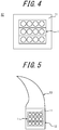
FIG. 4 is an axial schematic cross-sectional view of the bead core manufactured by the manufacturing method of the bead core according to the embodiment of the present disclosure; -
FIG. 5 is a schematic cross-sectional view illustrating an example of a structure in which a bead filler is disposed outside the bead core in a tire radial direction which is manufactured by the manufacturing method of the bead core according to the embodiment of the present disclosure; -
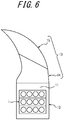
FIG. 6 is a schematic cross-sectional view illustrating another example of the structure in which the bead filler is disposed outside the bead core in the tire radial direction which is manufactured by the manufacturing method of the bead core according to the embodiment of the present disclosure; -
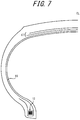
FIG. 7 is a tire widthwise cross-sectional view illustrating a tire widthwise half portion of an example of a pneumatic tire including, in each bead portion, the bead core manufactured by the manufacturing method of the bead core according to the embodiment of the present disclosure; and -
FIG. 8 is an axial schematic cross-sectional view of a bead core manufactured by a manufacturing method of the bead core according to another embodiment of the present disclosure. - Hereinafter, embodiments of the present disclosure will be illustrated and described in detail with reference to the drawings.
-
FIG. 1 is an axial cross-sectional view illustrating an example of an annular body formed by an annular body forming step in a manufacturing method of a bead core according to an embodiment of the present disclosure. In the present embodiment, astrip member 4 formed by coating one or morebead wires 2 with acoating resin 3 is wound to form an annular body 1 (an annular body forming step). Theannular body 1 illustrated inFIG. 1 is formed by winding thestrip member 4 formed by coating one or more (four in an illustrated example)bead wires 2 with thecoating resin 3, and thestrip member 4 that is almost rectangular in this cross section is layered in three stacks. In this example, fourbead wires 2 are arranged in an axial direction of theannular body 1, but the present disclosure is not especially limited to this case, and the number of thebead wires 2 may be one or more. - In the
bead wire 2, an arbitrary known material can be used and, for example, a steel cord can be used. The steel cord can comprise, for example, a steel monofilament or a stranded wire. Furthermore, in thebead wire 2, organic fibers, carbon fibers or the like may be used. - Additionally, in the
coating resin 3, for example, a thermoplastic elastomer or a thermoplastic resin can be used, or a resin that crosslinks by heat or an electron beam or a resin that cures by thermal dislocation can be used. Examples of the thermoplastic elastomer include polyolefin thermoplastic elastomer (TPO), polystyrene thermoplastic elastomer (TPS), polyamide thermoplastic elastomer (TPA), polyurethane thermoplastic elastomer (TPU), polyester thermoplastic elastomer (TPC), and dynamic crosslinking thermoplastic elastomer (TPV). Furthermore, examples of the thermoplastic resin include polyurethane resin, polyolefin resin, vinyl chloride resin, and polyamide resin. Furthermore, as the thermoplastic resin, a resin can be used in which, for example, a deflection temperature under load (under a load of 0.45 MPa) prescribed in ISO75-2 or ASTM D648 is 78°C or more, a tensile yield strength prescribed in JIS K7113 is 10 MPa or more, a tensile rupture elongation (JIS K7113) similarly prescribed in JIS K7113 is 50% or more, and Vicat softening temperature (A-method) prescribed in JIS K7206 is 130°C or more. It is preferable that thecoating resin 3 that coats thebead wire 2 has a tensile elastic modulus (prescribed in JIS K7113: 1995) of 50 MPa or more. Furthermore, it is preferable that the tensile elastic modulus of thecoating resin 3 that coats thebead wire 2 is 1000 MPa or less. Note that thecoating resin 3 mentioned herein does not contain a rubber (an organic polymer material that exhibits a rubber elasticity at normal temperature). - In the present embodiment, the
molten coating resin 3 is applied to an outer peripheral side of thebead wire 2, cooled and thereby solidified, to form thestrip member 4. A cross-sectional shape of the strip member 4 (a shape of a cross section orthogonal to an extending direction of the bead wire 2) is almost rectangular in the present embodiment, but is not limited to this example, and can be various shapes, for example, an almost parallelogram. Thestrip member 4 can be formed in a desired cross-sectional shape, for example, by use of an extruder. Then, theannular body 1 can be formed by winding and stacking thestrip member 4. The stacks can be joined to each other, for example, by winding thestrip member 4 while melting thecoating resin 3 by hot plate welding or the like and solidifying themolten coating resin 3. Alternatively, the stacks can be joined to each other by bonding the stacks with an adhesive or the like. -
FIG. 2 is a schematic side view illustrating the example of the annular body formed by the annular body forming step in the manufacturing method of the bead core according to the embodiment of the present disclosure as illustrated, for example, inFIG. 1 .FIG. 2 only illustrates thebead wire 2 for simplicity (FIG. 2 illustrates a center line of the bead wire 2), and omits depiction of thecoating resin 3. As illustrated inFIG. 2 , thebead wire 2 is wound from a winding start end E1 spirally in this cross-sectional view. F1, F2 and F3 indicate orbital positions, and in this example, a winding end edge E2 extends beyond at least a point F3. Therefore, when seen at an arbitrary radial position, thebead wire 2 is stacked in three or more stacks in this example. There are not any special restrictions on a length (an overlap length) of the bead wire from the orbital position (the point F3 in this example) located closest to a winding end edge E2 side to the winding end edge (a point E2 in this example). For example, the length can be from 1/200 to 199/200 of an orbital distance from a point F2 to the point F3. When the length is 1/200 or more of the orbital distance, an area where the coating resins come in contact with each other can increase between thebead wires 2 adjacent in a radial direction (a stack direction). Consequently, for example, an adhesiveness or a welding force can be increased, and a tensile burden can be decreased. On the other hand, when the length is 199/200 or less of the orbital distance, the bead core can have a reduced weight. For similar reasons, the overlap length is preferably from 1/100 to 2/3 of the orbital distance from the point F2 to the point F3, and more preferably from 1/50 to 1/3 of the orbital distance from the point F2 to the point F3. - In the present embodiment, subsequently to the above annular body forming step, the annular body formed in the above annular body forming step is coated with a resin (a resin coating step). Specifically, the step comprises a step of disposing the annular body formed in the annular body forming step in a cavity of a bead core forming injection mold, and injecting a molten injection resin to the cavity (an injection step).
-
FIG. 3 is a schematic cross-sectional view illustrating an example of an injection molding machine for use in the injection step in the manufacturing method of the bead core according to the embodiment of the present disclosure. In the injection step of the embodiment of the present disclosure, various known injection molding machines can be used. Hereinafter, an example of the machine will be described. As illustrated inFIG. 3 , aninjection molding machine 5 of this embodiment comprises aninjection unit 6 and a bead core forminginjection mold 7. Theinjection unit 6 includes ahopper 8, amotor 9, and acylinder 10. A tip of thecylinder 10 is provided with ahole 10a through which an injection resin 11 (non-illustrated inFIG. 3 ) is injected to the bead core forminginjection mold 7. Theinjection resin 11 thrown into thehopper 8 is fed from a rear portion of thecylinder 10 to a front portion (toward the bead core forming injection mold 7) by rotation of a screw (non-illustrated) driven by themotor 9. During this time, theinjection resin 11 is heated and molten with a heater (non-illustrated) installed around thecylinder 10. Then, themolten injection resin 11 is fed to the front portion of thecylinder 10 and injected to the bead core forminginjection mold 7. - As illustrated in
FIG. 3 , the bead core forminginjection mold 7 comprises two divided portions of afirst mold 7a and asecond mold 7b. Thefirst mold 7a includes a gate 7a1 through which theinjection resin 11 is fed from theinjection unit 6, and a recess portion defined by inner walls. Furthermore, thesecond mold 7b also includes a recess portion defined by inner walls. Consequently, in a case where thefirst mold 7a is brought into contact with thesecond mold 7b to place the bead core forminginjection mold 7 in a closed state (FIG. 3 illustrates this closed state), acavity 7c having a shape corresponding to two recess portions (the combined recess portions) is defined and formed in themold 7. In an illustrated example, thecavity 7c has an almost square cross section. - The
first mold 7a and thesecond mold 7b can be opened and closed by a non-illustrated mold clamping mechanism. In the present embodiment, the bead core forminginjection mold 7 is placed in an opened state, to dispose theannular body 1 formed in the above annular body forming step between thefirst mold 7a and thesecond mold 7b. Then, the bead core forminginjection mold 7 is placed in the closed state, thereby disposing theannular body 1 in thecavity 7c of the bead core forminginjection mold 7. Note that it is preferable to fix theannular body 1 with a jig or the like and to dispose and locate the entireannular body 1 in thecavity 7c (especially in a center of thecavity 7c) in a case where the bead core forminginjection mold 7 comes in the closed state. - In the present embodiment, the above injection step is performed using, for example, the
injection molding machine 5 described above. In the present embodiment, subsequently to the injection step, the injectedinjection resin 11 is cooled and thereby solidified (a cooling step). In the cooling, the resin can be cooled and solidified in themold 7 having an interior controlled at a temperature lower than a resin melting point. -
FIG. 4 is an axial schematic cross-sectional view of the bead core manufactured by the manufacturing method of the bead core according to the embodiment of the present disclosure. After the above cooling step, the bead core forminginjection mold 7 is placed in the opened state, and a completedbead core 12 is removed from the bead core forminginjection mold 7. Thebead core 12 includes theannular body 1 having a configuration where a circumference (an entire circumference in an illustrated example) of theannular body 1 is covered with the solidifiedinjection resin 11. - According to the manufacturing method of the bead core of the present embodiment, the stacked
annular body 1 receives a force of thermal contraction due to theinjection resin 11 injected to the circumference of the annular body in the above cooling step. Consequently, theannular body 1 can be fastened with the surroundinginjection resin 11. Then, thebead core 12 has a configuration where the circumference (the entire circumference in the present embodiment) of theannular body 1 is covered with the solidifiedinjection resin 11. Consequently, the surrounding solidifiedinjection resin 11 can protect theannular body 1 against an external force such as a lateral force of the tire. Additionally, theannular body 1 is fastened with the surrounding solidifiedinjection resin 11, so that shape collapse of the annular body can be inhibited. As described above, according to the manufacturing method of the bead core of the present disclosure, thebead core 12 having a high durability is obtainable. -
FIG. 5 is a schematic cross-sectional view illustrating another example of a structure in which a bead filler is disposed outside the bead core in a tire radial direction which is manufactured by the manufacturing method of the bead core according to the embodiment of the present disclosure. As illustrated inFIG. 5 , abead filler 13 can be disposed outside thebead core 12 in the tire radial direction. In the example illustrated inFIG. 5 , thebead filler 13 may be made of a resin or a rubber. - In a case where the
bead filler 13 is made of the resin, such a resin can be the same resin as theinjection resin 11, or a resin different from theinjection resin 11. Furthermore, in the case where thebead filler 13 is made of the resin, a hardness of thebead filler 13 may be larger than, equal to, or smaller than a hardness of theinjection resin 11. Furthermore, in a case where thebead filler 13 is made of the rubber, the hardness of thebead filler 13 is generally smaller than the hardness of theinjection resin 11, but may be larger than or equal to the hardness. -
FIG. 6 is a schematic cross-sectional view illustrating an example of the structure in which the bead filler is disposed outside the bead core in the tire radial direction which is manufactured by the manufacturing method of the bead core according to the present embodiment. In this example, thebead filler 13 comprises a radiallyinner side portion 14 and a radiallyouter side portion 15. Also in this case, thebead filler 13 may be made of the resin or the rubber. Both of the radiallyinner side portion 14 and the radiallyouter side portion 15 can be made of the resin or the rubber. Alternatively, one of the portions can be made of the resin and the other portion can be made of the rubber. - The
bead core 12, the radiallyinner side portion 14 of thebead filler 13 and the radiallyouter side portion 15 of thebead filler 13 can have an arbitrarily set magnitude relation in hardness, but it is preferable that the hardness of the radiallyouter side portion 15 is smaller than the hardness of the radiallyinner side portion 14. The reason is that a difference in rigidity from a sidewall portion can be decreased. Note that in a case where the radiallyinner side portion 14 and the radiallyouter side portion 15 are made of the resin, the radiallyinner side portion 14 and the radiallyouter side portion 15 can be welded and bonded. In a case where thebead core 12 and the radiallyinner side portion 14 of thebead filler 13 are both made of the resin, the bead core and the portion can be joined, for example, by welding or bonding with an adhesive or the like. In a case where at least one of thebead core 12 and the radiallyinner side portion 14 of thebead filler 13 is made of the rubber, the bead core and the portion can be joined, for example, by the bonding with the adhesive or the like. - The structures illustrated in
FIG. 5 andFIG. 6 are applicable to a bead portion of a pneumatic tire including a pair of bead portions.FIG. 7 is a tire widthwise cross-sectional view illustrating a tire widthwise half portion of the pneumatic tire including, in each bead portion, the bead core manufactured by the manufacturing method of the bead core according to the embodiment of the present disclosure.FIG. 7 only illustrates the tire widthwise half portion with a tire equatorial plane CL as a boundary, but another non-illustrated half portion also has a similar configuration. As an example, as illustrated inFIG. 7 , the tire comprises thebead core 12 manufactured by the manufacturing method of the bead core according to the embodiment of the present disclosure and embedded in each of the pair of bead portions, and includes a belt comprising two belt layers in the illustrated example on a tire radially outer side of acarcass 16 that toroidally straddles thebead core 12. - In the present disclosure, it is preferable that in the injection step, the entire
annular body 1 is disposed to be located in thecavity 7c and theinjection resin 11 is injected to the entire circumference of theannular body 1 as in the above embodiment. The reason is that an effect of fastening theannular body 1 due to the thermal contraction can further improve, and the bead core having a higher durability is obtainable. On the other hand, in the present disclosure, the injection step can comprise disposing and locating a part of theannular body 1 in thecavity 7c, and injecting theinjection resin 11 in a part of the circumference of theannular body 1. - In the present disclosure, from a viewpoint of obtaining the
bead core 12 having the high durability more easily, it is preferable that theinjection resin 11 is the same resin as thecoating resin 3. In this case, it is easy to weld or bond theinjection resin 11 and thecoating resin 3. - In the present disclosure, from a viewpoint of easily adjusting the hardness of the
bead core 12, it is preferable that theinjection resin 11 is the resin different from thecoating resin 3. Here, in general, the resin has a larger hardness than the rubber. Consequently, to decrease the difference in rigidity between thebead core 12 and the surrounding rubber, it is preferable that theinjection resin 11 adjacent directly to the rubber has a smaller hardness than the coating resin 3 (the hardness is close to the hardness of the rubber). On the other hand, to further obtain the effect of the thermal contraction, it is preferable that theinjection resin 11 has a larger hardness than thecoating resin 3. - Alternatively, it is preferable to use a resin having a high adhesiveness to the rubber as the
injection resin 11. -
FIG. 8 is an axial schematic cross-sectional view of a bead core manufactured by a manufacturing method of the bead core according to another embodiment of the present disclosure. In this embodiment, a resin coating step comprises depositing afirst film 18 and asecond film 19, which are made of a resin, in order on anannular body 1 formed by an annular body forming step by three-dimensional lamination, so that thefirst film 18 and the second film cover a circumference (an entire circumference in this example) of theannular body 1. Note that a known technique can be used in the three-dimensional lamination. Furthermore, each of thefirst film 18 and thesecond film 19 may comprise a single layer or multiple layers. Additionally, in thefirst film 18 and thesecond film 19, the same material (the same resin) may be used, or different materials (different resins) may be used. Note that in the embodiment illustrated inFIG. 8 , the two first and second films are deposited, but three or more films may be deposited. - Also in the embodiment illustrated in
FIG. 8 , by cooling after the films are heated, theannular body 1 receives a force of thermal contraction from thefirst film 18 and thesecond film 19. Furthermore, theannular body 1 is protected from an external force or the like by thefirst film 18 and thesecond film 19. - Therefore, also according to the manufacturing method of the bead core of the embodiment illustrated in
FIG. 8 , abead core 12 having a high durability is obtainable. - As above, the present disclosure has been described, but the present disclosure is not limited to the above embodiments and examples. For example, in the examples illustrated in
FIG. 1 andFIG. 4 , three stacks are stacked in the cross section of theannular body 1, but, for example, four or more stacks may be stacked. -
- 1
- annular body
- 2
- bead wire
- 3
- coating resin
- 4
- strip member
- 5
- injection molding machine
- 6
- injection unit
- 7
- bead core forming injection mold
- 7a
- first mold
- 7a1
- gate
- 7b
- second mold
- 7c
- cavity
- 8
- hopper
- 9
- motor
- 10
- cylinder
- 10a
- hole
- 11
- injection resin
- 12
- bead core
- 13
- bead filler
- 14
- radially inner side portion
- 15
- radially outer side portion
- 16
- carcass
- 17
- belt
- 18
- first film
- 19
- second film
- CL
- tire equatorial plane
Claims (5)
- A manufacturing method of a bead core comprising:an annular body forming step of winding a strip member formed by coating one or more bead wires with a coating resin to form an annular body, anda resin coating step of coating the annular body formed in the annular body forming step with a resin.
- The manufacturing method of the bead core according to claim 1, wherein the resin coating step includes an injection step of disposing the annular body formed in the annular body forming step in a cavity of a bead core forming injection mold, and injecting a molten injection resin to the cavity.
- The manufacturing method of the bead core according to claim 2, wherein in the injection step, the entire annular body is disposed to be located in the cavity, and the injection resin is injected to an entire circumference of the annular body.
- The manufacturing method of the bead core according to any one of claims 1 to 3, wherein the resin is the same resin as the coating resin.
- The manufacturing method of the bead core according to any one of claims 1 to 3, wherein the resin is a resin different from the coating resin.
Applications Claiming Priority (2)
| Application Number | Priority Date | Filing Date | Title |
|---|---|---|---|
| JP2017119967A JP6873837B2 (en) | 2017-06-19 | 2017-06-19 | How to manufacture bead core |
| PCT/JP2018/019715 WO2018235505A1 (en) | 2017-06-19 | 2018-05-22 | Method of manufacturing bead core |
Publications (3)
| Publication Number | Publication Date |
|---|---|
| EP3643489A1 true EP3643489A1 (en) | 2020-04-29 |
| EP3643489A4 EP3643489A4 (en) | 2021-03-10 |
| EP3643489B1 EP3643489B1 (en) | 2023-06-07 |
Family
ID=64735702
Family Applications (1)
| Application Number | Title | Priority Date | Filing Date |
|---|---|---|---|
| EP18819648.9A Active EP3643489B1 (en) | 2017-06-19 | 2018-05-22 | Production method for bead core |
Country Status (5)
| Country | Link |
|---|---|
| US (2) | US20200369096A1 (en) |
| EP (1) | EP3643489B1 (en) |
| JP (1) | JP6873837B2 (en) |
| CN (1) | CN110770014A (en) |
| WO (1) | WO2018235505A1 (en) |
Families Citing this family (1)
| Publication number | Priority date | Publication date | Assignee | Title |
|---|---|---|---|---|
| JP2020055494A (en) * | 2018-10-04 | 2020-04-09 | 株式会社ブリヂストン | tire |
Family Cites Families (14)
| Publication number | Priority date | Publication date | Assignee | Title |
|---|---|---|---|---|
| FR2576247B1 (en) * | 1985-01-18 | 1987-07-31 | Michelin & Cie | REINFORCING ASSEMBLIES COMPRISING REINFORCEMENT THREADS AND A MATRIX; PROCESS FOR OBTAINING SUCH ASSEMBLIES; ARTICLES COMPRISING SUCH PACKAGES |
| US5127456A (en) * | 1985-01-18 | 1992-07-07 | Compagnie Generale Des Etablissements Michelin | Sheathed bead ring to pneumatic tires; method of producing such a bead ring; pneumatic tires having such a bead ring |
| JP3266704B2 (en) * | 1993-07-30 | 2002-03-18 | オーツタイヤ株式会社 | Bead for tire |
| JP3848771B2 (en) * | 1998-01-09 | 2006-11-22 | 横浜ゴム株式会社 | Pneumatic tire |
| CN1769077A (en) * | 2004-11-06 | 2006-05-10 | 福建省漳州市天天利轮胎有限公司 | Nano bullet proof tyre and its manufacturing method |
| JP2008114490A (en) * | 2006-11-06 | 2008-05-22 | Toyo Tire & Rubber Co Ltd | Mold for bead material |
| JP5124164B2 (en) * | 2007-04-20 | 2013-01-23 | 株式会社ブリヂストン | Aircraft pneumatic tire |
| WO2011122450A1 (en) * | 2010-03-30 | 2011-10-06 | 株式会社ブリヂストン | Tire manufacturing method, tire, and tire forming mold |
| JP5588208B2 (en) | 2010-03-30 | 2014-09-10 | 株式会社ブリヂストン | Tire manufacturing method and tire |
| JP5454350B2 (en) * | 2010-05-13 | 2014-03-26 | 横浜ゴム株式会社 | Pneumatic tire |
| US9902121B2 (en) * | 2011-12-12 | 2018-02-27 | Bridgestone Corporation | Tire |
| JP6398722B2 (en) * | 2012-11-30 | 2018-10-03 | 横浜ゴム株式会社 | Pneumatic tire |
| CN106457930B (en) * | 2014-05-13 | 2018-02-02 | 株式会社普利司通 | Tires and tire manufacturing methods |
| JP2016101810A (en) * | 2014-11-27 | 2016-06-02 | 東洋ゴム工業株式会社 | Pneumatic tire and method for production thereof |
-
2017
- 2017-06-19 JP JP2017119967A patent/JP6873837B2/en active Active
-
2018
- 2018-05-22 EP EP18819648.9A patent/EP3643489B1/en active Active
- 2018-05-22 US US16/621,486 patent/US20200369096A1/en not_active Abandoned
- 2018-05-22 CN CN201880040946.7A patent/CN110770014A/en active Pending
- 2018-05-22 WO PCT/JP2018/019715 patent/WO2018235505A1/en not_active Ceased
-
2021
- 2021-08-11 US US17/444,846 patent/US20210370725A1/en not_active Abandoned
Also Published As
| Publication number | Publication date |
|---|---|
| US20210370725A1 (en) | 2021-12-02 |
| CN110770014A (en) | 2020-02-07 |
| JP2019001415A (en) | 2019-01-10 |
| JP6873837B2 (en) | 2021-05-19 |
| US20200369096A1 (en) | 2020-11-26 |
| WO2018235505A1 (en) | 2018-12-27 |
| EP3643489A4 (en) | 2021-03-10 |
| EP3643489B1 (en) | 2023-06-07 |
Similar Documents
| Publication | Publication Date | Title |
|---|---|---|
| EP3225425B1 (en) | Tire | |
| EP3225424B1 (en) | Tire | |
| EP3643532B1 (en) | Bead member and pneumatic tire | |
| US20210370725A1 (en) | Manufacturing method of bead core | |
| US20200207158A1 (en) | Bead member, pneumatic tire, and assembly | |
| EP3643529A1 (en) | Bead core, production method therefor, and pneumatic tire | |
| EP3643487A1 (en) | Pneumatic tire production method | |
| JP6408070B2 (en) | tire | |
| EP3643486A1 (en) | Production method for pneumatic tire, and pneumatic tire | |
| EP3643531A1 (en) | Bead core | |
| EP3643530B1 (en) | Bead core, production method therefor, and pneumatic tire | |
| WO2021112049A1 (en) | Fiber, method for manufacturing resin-coated cord, method for manufacturing pneumatic tire | |
| US20200114691A1 (en) | Pneumatic tire | |
| WO2019244776A1 (en) | Pneumatic tyre | |
| JP6989224B2 (en) | Manufacturing method of belt layer constituent members | |
| JP2025162467A (en) | Tire and tire manufacturing method | |
| WO2025220266A1 (en) | Tire and method for manufacturing tire | |
| WO2025220268A1 (en) | Tire and method for manufacturing tire | |
| JP2025162463A (en) | Tire and tire manufacturing method | |
| WO2019244721A1 (en) | Pneumatic tire |
Legal Events
| Date | Code | Title | Description |
|---|---|---|---|
| STAA | Information on the status of an ep patent application or granted ep patent |
Free format text: STATUS: THE INTERNATIONAL PUBLICATION HAS BEEN MADE |
|
| PUAI | Public reference made under article 153(3) epc to a published international application that has entered the european phase |
Free format text: ORIGINAL CODE: 0009012 |
|
| STAA | Information on the status of an ep patent application or granted ep patent |
Free format text: STATUS: REQUEST FOR EXAMINATION WAS MADE |
|
| 17P | Request for examination filed |
Effective date: 20191217 |
|
| AK | Designated contracting states |
Kind code of ref document: A1 Designated state(s): AL AT BE BG CH CY CZ DE DK EE ES FI FR GB GR HR HU IE IS IT LI LT LU LV MC MK MT NL NO PL PT RO RS SE SI SK SM TR |
|
| AX | Request for extension of the european patent |
Extension state: BA ME |
|
| DAV | Request for validation of the european patent (deleted) | ||
| DAX | Request for extension of the european patent (deleted) | ||
| A4 | Supplementary search report drawn up and despatched |
Effective date: 20210204 |
|
| RIC1 | Information provided on ipc code assigned before grant |
Ipc: B29D 30/48 20060101AFI20210129BHEP Ipc: B60C 15/04 20060101ALI20210129BHEP |
|
| GRAP | Despatch of communication of intention to grant a patent |
Free format text: ORIGINAL CODE: EPIDOSNIGR1 |
|
| STAA | Information on the status of an ep patent application or granted ep patent |
Free format text: STATUS: GRANT OF PATENT IS INTENDED |
|
| INTG | Intention to grant announced |
Effective date: 20221215 |
|
| GRAS | Grant fee paid |
Free format text: ORIGINAL CODE: EPIDOSNIGR3 |
|
| GRAA | (expected) grant |
Free format text: ORIGINAL CODE: 0009210 |
|
| STAA | Information on the status of an ep patent application or granted ep patent |
Free format text: STATUS: THE PATENT HAS BEEN GRANTED |
|
| AK | Designated contracting states |
Kind code of ref document: B1 Designated state(s): AL AT BE BG CH CY CZ DE DK EE ES FI FR GB GR HR HU IE IS IT LI LT LU LV MC MK MT NL NO PL PT RO RS SE SI SK SM TR |
|
| REG | Reference to a national code |
Ref country code: GB Ref legal event code: FG4D |
|
| REG | Reference to a national code |
Ref country code: CH Ref legal event code: EP Ref country code: AT Ref legal event code: REF Ref document number: 1573806 Country of ref document: AT Kind code of ref document: T Effective date: 20230615 Ref country code: DE Ref legal event code: R096 Ref document number: 602018051398 Country of ref document: DE |
|
| P01 | Opt-out of the competence of the unified patent court (upc) registered |
Effective date: 20230526 |
|
| REG | Reference to a national code |
Ref country code: LT Ref legal event code: MG9D |
|
| REG | Reference to a national code |
Ref country code: NL Ref legal event code: MP Effective date: 20230607 |
|
| PG25 | Lapsed in a contracting state [announced via postgrant information from national office to epo] |
Ref country code: SE Free format text: LAPSE BECAUSE OF FAILURE TO SUBMIT A TRANSLATION OF THE DESCRIPTION OR TO PAY THE FEE WITHIN THE PRESCRIBED TIME-LIMIT Effective date: 20230607 Ref country code: NO Free format text: LAPSE BECAUSE OF FAILURE TO SUBMIT A TRANSLATION OF THE DESCRIPTION OR TO PAY THE FEE WITHIN THE PRESCRIBED TIME-LIMIT Effective date: 20230907 Ref country code: ES Free format text: LAPSE BECAUSE OF FAILURE TO SUBMIT A TRANSLATION OF THE DESCRIPTION OR TO PAY THE FEE WITHIN THE PRESCRIBED TIME-LIMIT Effective date: 20230607 |
|
| REG | Reference to a national code |
Ref country code: AT Ref legal event code: MK05 Ref document number: 1573806 Country of ref document: AT Kind code of ref document: T Effective date: 20230607 |
|
| PG25 | Lapsed in a contracting state [announced via postgrant information from national office to epo] |
Ref country code: RS Free format text: LAPSE BECAUSE OF FAILURE TO SUBMIT A TRANSLATION OF THE DESCRIPTION OR TO PAY THE FEE WITHIN THE PRESCRIBED TIME-LIMIT Effective date: 20230607 Ref country code: NL Free format text: LAPSE BECAUSE OF FAILURE TO SUBMIT A TRANSLATION OF THE DESCRIPTION OR TO PAY THE FEE WITHIN THE PRESCRIBED TIME-LIMIT Effective date: 20230607 Ref country code: LV Free format text: LAPSE BECAUSE OF FAILURE TO SUBMIT A TRANSLATION OF THE DESCRIPTION OR TO PAY THE FEE WITHIN THE PRESCRIBED TIME-LIMIT Effective date: 20230607 Ref country code: LT Free format text: LAPSE BECAUSE OF FAILURE TO SUBMIT A TRANSLATION OF THE DESCRIPTION OR TO PAY THE FEE WITHIN THE PRESCRIBED TIME-LIMIT Effective date: 20230607 Ref country code: HR Free format text: LAPSE BECAUSE OF FAILURE TO SUBMIT A TRANSLATION OF THE DESCRIPTION OR TO PAY THE FEE WITHIN THE PRESCRIBED TIME-LIMIT Effective date: 20230607 Ref country code: GR Free format text: LAPSE BECAUSE OF FAILURE TO SUBMIT A TRANSLATION OF THE DESCRIPTION OR TO PAY THE FEE WITHIN THE PRESCRIBED TIME-LIMIT Effective date: 20230908 |
|
| PG25 | Lapsed in a contracting state [announced via postgrant information from national office to epo] |
Ref country code: FI Free format text: LAPSE BECAUSE OF FAILURE TO SUBMIT A TRANSLATION OF THE DESCRIPTION OR TO PAY THE FEE WITHIN THE PRESCRIBED TIME-LIMIT Effective date: 20230607 |
|
| PG25 | Lapsed in a contracting state [announced via postgrant information from national office to epo] |
Ref country code: SK Free format text: LAPSE BECAUSE OF FAILURE TO SUBMIT A TRANSLATION OF THE DESCRIPTION OR TO PAY THE FEE WITHIN THE PRESCRIBED TIME-LIMIT Effective date: 20230607 |
|
| PG25 | Lapsed in a contracting state [announced via postgrant information from national office to epo] |
Ref country code: IS Free format text: LAPSE BECAUSE OF FAILURE TO SUBMIT A TRANSLATION OF THE DESCRIPTION OR TO PAY THE FEE WITHIN THE PRESCRIBED TIME-LIMIT Effective date: 20231007 |
|
| PG25 | Lapsed in a contracting state [announced via postgrant information from national office to epo] |
Ref country code: SM Free format text: LAPSE BECAUSE OF FAILURE TO SUBMIT A TRANSLATION OF THE DESCRIPTION OR TO PAY THE FEE WITHIN THE PRESCRIBED TIME-LIMIT Effective date: 20230607 Ref country code: SK Free format text: LAPSE BECAUSE OF FAILURE TO SUBMIT A TRANSLATION OF THE DESCRIPTION OR TO PAY THE FEE WITHIN THE PRESCRIBED TIME-LIMIT Effective date: 20230607 Ref country code: RO Free format text: LAPSE BECAUSE OF FAILURE TO SUBMIT A TRANSLATION OF THE DESCRIPTION OR TO PAY THE FEE WITHIN THE PRESCRIBED TIME-LIMIT Effective date: 20230607 Ref country code: PT Free format text: LAPSE BECAUSE OF FAILURE TO SUBMIT A TRANSLATION OF THE DESCRIPTION OR TO PAY THE FEE WITHIN THE PRESCRIBED TIME-LIMIT Effective date: 20231009 Ref country code: IS Free format text: LAPSE BECAUSE OF FAILURE TO SUBMIT A TRANSLATION OF THE DESCRIPTION OR TO PAY THE FEE WITHIN THE PRESCRIBED TIME-LIMIT Effective date: 20231007 Ref country code: EE Free format text: LAPSE BECAUSE OF FAILURE TO SUBMIT A TRANSLATION OF THE DESCRIPTION OR TO PAY THE FEE WITHIN THE PRESCRIBED TIME-LIMIT Effective date: 20230607 Ref country code: CZ Free format text: LAPSE BECAUSE OF FAILURE TO SUBMIT A TRANSLATION OF THE DESCRIPTION OR TO PAY THE FEE WITHIN THE PRESCRIBED TIME-LIMIT Effective date: 20230607 Ref country code: AT Free format text: LAPSE BECAUSE OF FAILURE TO SUBMIT A TRANSLATION OF THE DESCRIPTION OR TO PAY THE FEE WITHIN THE PRESCRIBED TIME-LIMIT Effective date: 20230607 |
|
| PG25 | Lapsed in a contracting state [announced via postgrant information from national office to epo] |
Ref country code: PL Free format text: LAPSE BECAUSE OF FAILURE TO SUBMIT A TRANSLATION OF THE DESCRIPTION OR TO PAY THE FEE WITHIN THE PRESCRIBED TIME-LIMIT Effective date: 20230607 |
|
| REG | Reference to a national code |
Ref country code: DE Ref legal event code: R097 Ref document number: 602018051398 Country of ref document: DE |
|
| PLBE | No opposition filed within time limit |
Free format text: ORIGINAL CODE: 0009261 |
|
| STAA | Information on the status of an ep patent application or granted ep patent |
Free format text: STATUS: NO OPPOSITION FILED WITHIN TIME LIMIT |
|
| PG25 | Lapsed in a contracting state [announced via postgrant information from national office to epo] |
Ref country code: DK Free format text: LAPSE BECAUSE OF FAILURE TO SUBMIT A TRANSLATION OF THE DESCRIPTION OR TO PAY THE FEE WITHIN THE PRESCRIBED TIME-LIMIT Effective date: 20230607 |
|
| PG25 | Lapsed in a contracting state [announced via postgrant information from national office to epo] |
Ref country code: SI Free format text: LAPSE BECAUSE OF FAILURE TO SUBMIT A TRANSLATION OF THE DESCRIPTION OR TO PAY THE FEE WITHIN THE PRESCRIBED TIME-LIMIT Effective date: 20230607 |
|
| 26N | No opposition filed |
Effective date: 20240308 |
|
| PG25 | Lapsed in a contracting state [announced via postgrant information from national office to epo] |
Ref country code: SI Free format text: LAPSE BECAUSE OF FAILURE TO SUBMIT A TRANSLATION OF THE DESCRIPTION OR TO PAY THE FEE WITHIN THE PRESCRIBED TIME-LIMIT Effective date: 20230607 Ref country code: IT Free format text: LAPSE BECAUSE OF FAILURE TO SUBMIT A TRANSLATION OF THE DESCRIPTION OR TO PAY THE FEE WITHIN THE PRESCRIBED TIME-LIMIT Effective date: 20230607 |
|
| PG25 | Lapsed in a contracting state [announced via postgrant information from national office to epo] |
Ref country code: BG Free format text: LAPSE BECAUSE OF FAILURE TO SUBMIT A TRANSLATION OF THE DESCRIPTION OR TO PAY THE FEE WITHIN THE PRESCRIBED TIME-LIMIT Effective date: 20230607 |
|
| PG25 | Lapsed in a contracting state [announced via postgrant information from national office to epo] |
Ref country code: BG Free format text: LAPSE BECAUSE OF FAILURE TO SUBMIT A TRANSLATION OF THE DESCRIPTION OR TO PAY THE FEE WITHIN THE PRESCRIBED TIME-LIMIT Effective date: 20230607 |
|
| REG | Reference to a national code |
Ref country code: CH Ref legal event code: PL |
|
| PG25 | Lapsed in a contracting state [announced via postgrant information from national office to epo] |
Ref country code: MC Free format text: LAPSE BECAUSE OF FAILURE TO SUBMIT A TRANSLATION OF THE DESCRIPTION OR TO PAY THE FEE WITHIN THE PRESCRIBED TIME-LIMIT Effective date: 20230607 |
|
| PG25 | Lapsed in a contracting state [announced via postgrant information from national office to epo] |
Ref country code: LU Free format text: LAPSE BECAUSE OF NON-PAYMENT OF DUE FEES Effective date: 20240522 |
|
| GBPC | Gb: european patent ceased through non-payment of renewal fee |
Effective date: 20240522 |
|
| PG25 | Lapsed in a contracting state [announced via postgrant information from national office to epo] |
Ref country code: MC Free format text: LAPSE BECAUSE OF FAILURE TO SUBMIT A TRANSLATION OF THE DESCRIPTION OR TO PAY THE FEE WITHIN THE PRESCRIBED TIME-LIMIT Effective date: 20230607 Ref country code: LU Free format text: LAPSE BECAUSE OF NON-PAYMENT OF DUE FEES Effective date: 20240522 Ref country code: CH Free format text: LAPSE BECAUSE OF NON-PAYMENT OF DUE FEES Effective date: 20240531 |
|
| REG | Reference to a national code |
Ref country code: BE Ref legal event code: MM Effective date: 20240531 |
|
| PG25 | Lapsed in a contracting state [announced via postgrant information from national office to epo] |
Ref country code: IE Free format text: LAPSE BECAUSE OF NON-PAYMENT OF DUE FEES Effective date: 20240522 |
|
| PG25 | Lapsed in a contracting state [announced via postgrant information from national office to epo] |
Ref country code: BE Free format text: LAPSE BECAUSE OF NON-PAYMENT OF DUE FEES Effective date: 20240531 |
|
| PG25 | Lapsed in a contracting state [announced via postgrant information from national office to epo] |
Ref country code: GB Free format text: LAPSE BECAUSE OF NON-PAYMENT OF DUE FEES Effective date: 20240522 |
|
| PG25 | Lapsed in a contracting state [announced via postgrant information from national office to epo] |
Ref country code: CY Free format text: LAPSE BECAUSE OF FAILURE TO SUBMIT A TRANSLATION OF THE DESCRIPTION OR TO PAY THE FEE WITHIN THE PRESCRIBED TIME-LIMIT; INVALID AB INITIO Effective date: 20180522 |
|
| PG25 | Lapsed in a contracting state [announced via postgrant information from national office to epo] |
Ref country code: HU Free format text: LAPSE BECAUSE OF FAILURE TO SUBMIT A TRANSLATION OF THE DESCRIPTION OR TO PAY THE FEE WITHIN THE PRESCRIBED TIME-LIMIT; INVALID AB INITIO Effective date: 20180522 |
|
| PG25 | Lapsed in a contracting state [announced via postgrant information from national office to epo] |
Ref country code: TR Free format text: LAPSE BECAUSE OF FAILURE TO SUBMIT A TRANSLATION OF THE DESCRIPTION OR TO PAY THE FEE WITHIN THE PRESCRIBED TIME-LIMIT Effective date: 20230607 |
|
| PGFP | Annual fee paid to national office [announced via postgrant information from national office to epo] |
Ref country code: DE Payment date: 20260522 Year of fee payment: 9 |
|
| PGFP | Annual fee paid to national office [announced via postgrant information from national office to epo] |
Ref country code: FR Payment date: 20260526 Year of fee payment: 9 |