EP3643415A1 - Rotationsreinigungsdüse und reinigungssystem zum reinigen von oberflächen in einer getränkeabfüllanlage - Google Patents
Rotationsreinigungsdüse und reinigungssystem zum reinigen von oberflächen in einer getränkeabfüllanlage Download PDFInfo
- Publication number
- EP3643415A1 EP3643415A1 EP19203989.9A EP19203989A EP3643415A1 EP 3643415 A1 EP3643415 A1 EP 3643415A1 EP 19203989 A EP19203989 A EP 19203989A EP 3643415 A1 EP3643415 A1 EP 3643415A1
- Authority
- EP
- European Patent Office
- Prior art keywords
- nozzle
- control unit
- rotary cleaning
- nozzle head
- cleaning
- Prior art date
- Legal status (The legal status is an assumption and is not a legal conclusion. Google has not performed a legal analysis and makes no representation as to the accuracy of the status listed.)
- Granted
Links
Images



Classifications
-
- B—PERFORMING OPERATIONS; TRANSPORTING
- B67—OPENING, CLOSING OR CLEANING BOTTLES, JARS OR SIMILAR CONTAINERS; LIQUID HANDLING
- B67C—CLEANING, FILLING WITH LIQUIDS OR SEMILIQUIDS, OR EMPTYING, OF BOTTLES, JARS, CANS, CASKS, BARRELS, OR SIMILAR CONTAINERS, NOT OTHERWISE PROVIDED FOR; FUNNELS
- B67C3/00—Bottling liquids or semiliquids; Filling jars or cans with liquids or semiliquids using bottling or like apparatus; Filling casks or barrels with liquids or semiliquids
- B67C3/001—Cleaning of filling devices
-
- B—PERFORMING OPERATIONS; TRANSPORTING
- B08—CLEANING
- B08B—CLEANING IN GENERAL; PREVENTION OF FOULING IN GENERAL
- B08B3/00—Cleaning by methods involving the use or presence of liquid or steam
- B08B3/02—Cleaning by the force of jets or sprays
-
- B—PERFORMING OPERATIONS; TRANSPORTING
- B65—CONVEYING; PACKING; STORING; HANDLING THIN OR FILAMENTARY MATERIAL
- B65B—MACHINES, APPARATUS OR DEVICES FOR, OR METHODS OF, PACKAGING ARTICLES OR MATERIALS; UNPACKING
- B65B3/00—Packaging plastic material, semiliquids, liquids or mixed solids and liquids, in individual containers or receptacles, e.g. bags, sacks, boxes, cartons, cans, or jars
- B65B3/02—Machines characterised by the incorporation of means for making the containers or receptacles
- B65B3/022—Making containers by moulding of a thermoplastic material
-
- B—PERFORMING OPERATIONS; TRANSPORTING
- B05—SPRAYING OR ATOMISING IN GENERAL; APPLYING FLUENT MATERIALS TO SURFACES, IN GENERAL
- B05B—SPRAYING APPARATUS; ATOMISING APPARATUS; NOZZLES
- B05B1/00—Nozzles, spray heads or other outlets, with or without auxiliary devices such as valves, heating means
- B05B1/002—Nozzles, spray heads or other outlets, with or without auxiliary devices such as valves, heating means designed to reduce the generation or the transmission of noise or to produce a particular sound; associated with noise monitoring means
-
- B—PERFORMING OPERATIONS; TRANSPORTING
- B05—SPRAYING OR ATOMISING IN GENERAL; APPLYING FLUENT MATERIALS TO SURFACES, IN GENERAL
- B05B—SPRAYING APPARATUS; ATOMISING APPARATUS; NOZZLES
- B05B12/00—Arrangements for controlling delivery; Arrangements for controlling the spray area
- B05B12/004—Arrangements for controlling delivery; Arrangements for controlling the spray area comprising sensors for monitoring the delivery, e.g. by displaying the sensed value or generating an alarm
-
- B—PERFORMING OPERATIONS; TRANSPORTING
- B05—SPRAYING OR ATOMISING IN GENERAL; APPLYING FLUENT MATERIALS TO SURFACES, IN GENERAL
- B05B—SPRAYING APPARATUS; ATOMISING APPARATUS; NOZZLES
- B05B3/00—Spraying or sprinkling apparatus with moving outlet elements or moving deflecting elements
- B05B3/02—Spraying or sprinkling apparatus with moving outlet elements or moving deflecting elements with rotating elements
- B05B3/04—Spraying or sprinkling apparatus with moving outlet elements or moving deflecting elements with rotating elements driven by the liquid or other fluent material discharged, e.g. the liquid actuating a motor before passing to the outlet
- B05B3/06—Spraying or sprinkling apparatus with moving outlet elements or moving deflecting elements with rotating elements driven by the liquid or other fluent material discharged, e.g. the liquid actuating a motor before passing to the outlet by jet reaction
-
- B—PERFORMING OPERATIONS; TRANSPORTING
- B08—CLEANING
- B08B—CLEANING IN GENERAL; PREVENTION OF FOULING IN GENERAL
- B08B3/00—Cleaning by methods involving the use or presence of liquid or steam
- B08B3/02—Cleaning by the force of jets or sprays
- B08B3/024—Cleaning by means of spray elements moving over the surface to be cleaned
-
- B—PERFORMING OPERATIONS; TRANSPORTING
- B65—CONVEYING; PACKING; STORING; HANDLING THIN OR FILAMENTARY MATERIAL
- B65B—MACHINES, APPARATUS OR DEVICES FOR, OR METHODS OF, PACKAGING ARTICLES OR MATERIALS; UNPACKING
- B65B3/00—Packaging plastic material, semiliquids, liquids or mixed solids and liquids, in individual containers or receptacles, e.g. bags, sacks, boxes, cartons, cans, or jars
- B65B3/04—Methods of, or means for, filling the material into the containers or receptacles
-
- B—PERFORMING OPERATIONS; TRANSPORTING
- B65—CONVEYING; PACKING; STORING; HANDLING THIN OR FILAMENTARY MATERIAL
- B65B—MACHINES, APPARATUS OR DEVICES FOR, OR METHODS OF, PACKAGING ARTICLES OR MATERIALS; UNPACKING
- B65B57/00—Automatic control, checking, warning, or safety devices
-
- H—ELECTRICITY
- H02—GENERATION; CONVERSION OR DISTRIBUTION OF ELECTRIC POWER
- H02K—DYNAMO-ELECTRIC MACHINES
- H02K1/00—Details of the magnetic circuit
- H02K1/06—Details of the magnetic circuit characterised by the shape, form or construction
- H02K1/12—Stationary parts of the magnetic circuit
- H02K1/16—Stator cores with slots for windings
-
- H—ELECTRICITY
- H02—GENERATION; CONVERSION OR DISTRIBUTION OF ELECTRIC POWER
- H02K—DYNAMO-ELECTRIC MACHINES
- H02K1/00—Details of the magnetic circuit
- H02K1/06—Details of the magnetic circuit characterised by the shape, form or construction
- H02K1/12—Stationary parts of the magnetic circuit
- H02K1/17—Stator cores with permanent magnets
-
- H—ELECTRICITY
- H02—GENERATION; CONVERSION OR DISTRIBUTION OF ELECTRIC POWER
- H02K—DYNAMO-ELECTRIC MACHINES
- H02K1/00—Details of the magnetic circuit
- H02K1/06—Details of the magnetic circuit characterised by the shape, form or construction
- H02K1/22—Rotating parts of the magnetic circuit
- H02K1/26—Rotor cores with slots for windings
-
- H—ELECTRICITY
- H02—GENERATION; CONVERSION OR DISTRIBUTION OF ELECTRIC POWER
- H02K—DYNAMO-ELECTRIC MACHINES
- H02K1/00—Details of the magnetic circuit
- H02K1/06—Details of the magnetic circuit characterised by the shape, form or construction
- H02K1/22—Rotating parts of the magnetic circuit
- H02K1/27—Rotor cores with permanent magnets
- H02K1/2786—Outer rotors
- H02K1/2787—Outer rotors the magnetisation axis of the magnets being perpendicular to the rotor axis
- H02K1/2789—Outer rotors the magnetisation axis of the magnets being perpendicular to the rotor axis the rotor consisting of two or more circumferentially positioned magnets
- H02K1/2791—Surface mounted magnets; Inset magnets
-
- H—ELECTRICITY
- H02—GENERATION; CONVERSION OR DISTRIBUTION OF ELECTRIC POWER
- H02K—DYNAMO-ELECTRIC MACHINES
- H02K7/00—Arrangements for handling mechanical energy structurally associated with dynamo-electric machines, e.g. structural association with mechanical driving motors or auxiliary dynamo-electric machines
- H02K7/14—Structural association with mechanical loads, e.g. with hand-held machine tools or fans
-
- B—PERFORMING OPERATIONS; TRANSPORTING
- B05—SPRAYING OR ATOMISING IN GENERAL; APPLYING FLUENT MATERIALS TO SURFACES, IN GENERAL
- B05B—SPRAYING APPARATUS; ATOMISING APPARATUS; NOZZLES
- B05B1/00—Nozzles, spray heads or other outlets, with or without auxiliary devices such as valves, heating means
- B05B1/005—Nozzles or other outlets specially adapted for discharging one or more gases
-
- B—PERFORMING OPERATIONS; TRANSPORTING
- B05—SPRAYING OR ATOMISING IN GENERAL; APPLYING FLUENT MATERIALS TO SURFACES, IN GENERAL
- B05B—SPRAYING APPARATUS; ATOMISING APPARATUS; NOZZLES
- B05B13/00—Machines or plants for applying liquids or other fluent materials to surfaces of objects or other work by spraying, not covered by groups B05B1/00 - B05B11/00
- B05B13/06—Machines or plants for applying liquids or other fluent materials to surfaces of objects or other work by spraying, not covered by groups B05B1/00 - B05B11/00 specially designed for treating the inside of hollow bodies
- B05B13/0627—Arrangements of nozzles or spray heads specially adapted for treating the inside of hollow bodies
- B05B13/0636—Arrangements of nozzles or spray heads specially adapted for treating the inside of hollow bodies by means of rotatable spray heads or nozzles
-
- B—PERFORMING OPERATIONS; TRANSPORTING
- B08—CLEANING
- B08B—CLEANING IN GENERAL; PREVENTION OF FOULING IN GENERAL
- B08B9/00—Cleaning hollow articles by methods or apparatus specially adapted thereto
- B08B9/08—Cleaning containers, e.g. tanks
- B08B9/093—Cleaning containers, e.g. tanks by the force of jets or sprays
- B08B9/0936—Cleaning containers, e.g. tanks by the force of jets or sprays using rotating jets
-
- B—PERFORMING OPERATIONS; TRANSPORTING
- B65—CONVEYING; PACKING; STORING; HANDLING THIN OR FILAMENTARY MATERIAL
- B65B—MACHINES, APPARATUS OR DEVICES FOR, OR METHODS OF, PACKAGING ARTICLES OR MATERIALS; UNPACKING
- B65B2210/00—Specific aspects of the packaging machine
- B65B2210/06—Sterilising or cleaning machinery or conduits
-
- H—ELECTRICITY
- H02—GENERATION; CONVERSION OR DISTRIBUTION OF ELECTRIC POWER
- H02K—DYNAMO-ELECTRIC MACHINES
- H02K11/00—Structural association of dynamo-electric machines with electric components or with devices for shielding, monitoring or protection
- H02K11/04—Structural association of dynamo-electric machines with electric components or with devices for shielding, monitoring or protection for rectification
- H02K11/049—Rectifiers associated with stationary parts, e.g. stator cores
Definitions
- the present invention relates to a rotary cleaning nozzle and a cleaning system with such a rotary cleaning nozzle for cleaning surfaces in a beverage filling system, for example in an aseptic beverage filling system.
- aseptic systems are used in the packaging of food, in which process goods are processed under sterile conditions. These include, for example, aseptic beverage filling systems.
- Systems of this type have clean rooms that are delimited from the environment, through which both the containers to be filled and the filling product pass, and in which treatment stations for treating the containers are arranged.
- the treatment stations can include, for example, stretch blow molding stations for producing containers to be filled from preforms, rinsing stations for rinsing the containers, filling stations for filling the containers with a filling product and sealing stations for closing the containers filled with the filling product.
- the clean rooms are subjected to cleaning and subsequent sterilization, if necessary, for example after business interruptions.
- the cleaning is usually carried out by applying a cleaning medium to the respective system components, by means of which product residues can be rinsed off. A disinfection medium or a sterilization medium can then be applied.
- the respective cleaning, sterilization and / or Disinfection media are usually applied to the respective system components by means of nozzles introduced in the system.
- Stationary nozzles which can use different spray patterns are known from the nozzles for applying the respective cleaning, sterilizing and / or disinfecting media to the system components.
- Rotary cleaning nozzles are also known for spraying the respective cleaning, sterilizing and / or disinfecting media, which are used for special cleaning and disinfecting applications in the clean rooms.
- These rotary cleaning nozzles are characterized by a rotating nozzle head during operation, which can apply the respective cleaning, sterilization and / or disinfection media to the system components with a large-area and rotationally symmetrical spray pattern.
- the mechanical cleaning component can also be strengthened via the rotational movement, since a concentrated cleaning medium jet can periodically sweep over a predetermined area.
- Capacitive flow sensors are known from the prior art, which are arranged in a supply line upstream of the rotary cleaning nozzle and monitor a flow of the cleaning agent in the direction of the rotary cleaning nozzle. However, such a flow sensor cannot determine a malfunction caused by blocking the rotational movement of the nozzle head.
- the monitoring device comprises a contactor, in particular a magnet, which is in synchronism with the rotary cleaning nozzle is moved and has an inductive influence on a contact arranged outside the cleaning nozzle for monitoring the rotational frequency of the rotary cleaning nozzle.
- the rotary cleaning nozzle comprises an electrical generator for inducing electrical energy by rotating the nozzle head and a control unit for displaying a rotation of the nozzle head in dependence on the induced electrical energy.
- the electrical generator is set up to provide electrical energy induced by the rotation when it is operating properly, that is to say when the nozzle head is rotating.
- the energy induced in this way can be used by the control unit to indicate a rotation of the nozzle head and thus a correct operation of the rotation cleaning nozzle.
- the induced electrical energy can, however, not only be used as an indicator of the presence of a rotation of the nozzle head, but also to actuate the control unit.
- the electrical generator can serve as an energy source for the control unit.
- a small part of the kinetic and internal energy of the fluid flowing through the rotary cleaning nozzle can be used to operate the control unit.
- branching off small amounts of electrical energy for consumers with low power from energy sources already present in the system, such as a fluid flow also referred to as "energy harvesting".
- This structural and functional configuration enables the rotary cleaning nozzle to recognize and display a malfunction of the cleaning rotary nozzle independently, that is to say without coupling to components outside the rotary cleaning nozzle.
- a rotary cleaning nozzle is thus provided which is equipped with a monitoring system for malfunctions and at the same time has a modular structure in which dependencies and interfaces to other components, such as a stationary monitoring unit or a power supply, the beverage filling system are minimized.
- This modular structure has the effect that the proposed rotary cleaning nozzle can be used flexibly and interchangeably in common beverage filling systems without resulting in a high need for adaptation for the overall system.
- the proposed rotary cleaning nozzle is preferably provided for cleaning surfaces in a beverage filling system, but can be used in any aseptic system or other systems for cleaning surfaces.
- the cleaning effect of the rotary cleaning nozzle is due to the fluid emerging from the nozzle head via the nozzle outlet opening.
- the fluid can be gaseous or liquid.
- the fluid is preferably a cleaning agent which has a chemical structure which favors cleaning.
- the fluid can be a means for sterilizing the surfaces, a so-called sterilizer.
- the fluid can include, for example, hydrogen peroxide (H 2 O 2 ) or peracetic acid.
- the nozzle head can be rotated relative to the nozzle assembly.
- the rotary cleaning nozzle can be set up in such a way that the fluid to be supplied to the nozzle head during operation via the supply channel and to flow through it actuates the nozzle head in a rotary manner.
- the fluid can exert a force, in particular a recoil force, on the nozzle head, which causes a torque and thus the rotation of the nozzle head.
- the fluid flows through the nozzle head, it experiences a recoil and is actuated in a rotary manner.
- the nozzle head can be designed to eject the cleaning jet from the nozzle outlet opening in a direction away from a direction of rotation of the nozzle head, in particular a direction opposite to the direction of rotation, when the nozzle is rotated. Furthermore, the nozzle head can be designed such that the fluid is deflected when it flows through it. Correspondingly, the nozzle head can be provided with at least one feed section which deflects fluid that can be fed to the nozzle head via the feed channel in the direction of the nozzle outlet opening.
- the rotary cleaning nozzle can be set up in such a way that a rotary drive actuates the nozzle head in a rotary manner.
- the rotary drive can be an electric motor, for example.
- At least one slide bearing in particular a rotary slide bearing, can be provided between the nozzle head and the nozzle block.
- the plain bearing can be fitted with a clearance.
- the nozzle assembly can be sleeve-shaped. Accordingly, the nozzle head can be ring-shaped and pushed axially onto the nozzle assembly.
- a slide bearing can be provided at opposite ends of the nozzle head in the axial direction of the nozzle block, between which the at least one feed section of the nozzle head and the at least one feed opening of the nozzle block can be arranged.
- the nozzle assembly can be provided with a recess which is open on one side and forms the feed channel for the fluid.
- the feed channel preferably extends along an axial direction of the nozzle assembly.
- the recess designed as a feed channel can be cylindrical.
- the at least one feed opening can open into the recess.
- the feed opening can be designed in the form of a through opening in a side wall of the nozzle assembly and in particular extend along a radial direction of the nozzle assembly.
- the nozzle assembly can have a plurality of feed openings which can be formed at regular intervals from one another in the circumferential direction of the nozzle assembly. For example, the nozzle assembly can have two feed openings arranged opposite one another in its side wall.
- the rotary cleaning nozzle comprises the electrical generator.
- An electrical generator is generally understood to be a device for converting kinetic to electrical energy by means of electromagnetic induction.
- the basic structure of an electrical generator is known to the person skilled in the art from the prior art and is not described in detail here. Therefore, only special features of the rotary cleaning nozzle disclosed here are dealt with below.
- the generator in the rotary cleaning nozzle can comprise a rotor arranged on or in the nozzle head and a stator aligned thereto, arranged on or in the nozzle assembly.
- a stator is understood to mean a fixed component of the generator.
- a rotor is understood to mean a movable, in particular rotating, component of the generator.
- the rotor can be provided in the form of at least one magnet and the stator in the form of at least one induction coil.
- the rotor can be provided in the form of at least one induction coil and the stator in the form of at least one magnet.
- the nozzle head can be provided with the magnet and the nozzle assembly with the induction coil.
- the control unit can be arranged together with the induction coil in or on the nozzle assembly.
- the nozzle head with the induction coil and the nozzle assembly with the magnet can be provided.
- the control unit can be arranged together with the induction coil in or on the nozzle head.
- the magnet preferably comprises at least one permanent magnet.
- the magnet can be a magnetic ring made up of a plurality of permanent magnets, comprising a plurality of circumferentially arranged magnetic poles. Magnet poles arranged next to one another in the direction of rotation preferably have different polarities.
- the induction coil can be provided as a ring coil with a large number of windings.
- the generator can be provided in the form of a so-called claw-pole generator, in which the toroidal coil is embedded in a ferromagnetic cage or in a ferromagnetic sheathing.
- the cage can be provided in such a way that on a side facing the magnet, in particular the magnetic ring, the cage has a plurality is provided in the circumferential direction spaced apart, flat sections. In other words, on a side facing the magnet, the cage has gaps in the circumferential direction between the flat sections, which essentially extend along the entire width of the cage in a direction transverse to the circumferential direction. These flat sections spaced apart from one another in the circumferential direction are also referred to as so-called "claws".
- the number and position of the flat sections are preferably adapted to the number and position of the magnetic poles of the magnet facing the toroid.
- the number of flat sections preferably corresponds to the number of magnetic poles of the magnet.
- the flat sections are preferably aligned relative to the magnetic poles of the magnet. In other words, by rotating the nozzle head relative to the nozzle assembly, the magnet can be positioned relative to the cage and the ring coil embedded therein in such a way that a flat section of the cage faces a magnetic pole of the magnetic ring.
- This design of the generator which is proposed as a claw-pole generator, has the effect that high voltages and currents can be induced with a comparatively compact construction of the generator.
- a compact and powerful generator can be implemented in the rotary cleaning nozzle in this way.
- the generator in particular the induction coil, is preferably electrically conductively connected to the control unit in order to supply the control unit with the electrical energy induced by the generator.
- the control unit can accordingly be set up to indicate a rotation of the nozzle head when it is supplied with electrical energy induced by the generator.
- the electrical energy induced by the generator can be used to operate the control unit.
- the control unit can be operated in an on and an off state depending on the electrical energy supplied by the generator. More specifically, the control unit can be operated in the switched-on state in which a rotation of the nozzle head is indicated when electrical energy is supplied to the control unit by the generator. Accordingly, the control unit can be operated in the switched-off state in which a rotation of the nozzle head is not indicated when the supply of electrical energy is interrupted.
- the rotary cleaning nozzle can be set up to supply the electrical energy induced by the generator to the control unit in the form of direct current or alternating current.
- the electrical generator can be used to induce alternating current be set up, a commutator coupled to the rotation of the nozzle head or a rectifier, for example a bridge rectifier or a one-way rectifier, can be interposed between the generator and the control unit.
- the control unit can be supplied with the electrical energy induced by the generator in the form of direct current.
- the rotary cleaning nozzle can comprise an energy store, in particular in the form of a capacitor.
- the energy store is preferably electrically conductively connected to the generator, in particular the induction coil. Accordingly, the energy store can be rechargeable by the electrical energy induced by the generator.
- the rotary cleaning nozzle can be designed such that energy induced by the generator can be supplied to the energy store in the form of direct current.
- a commutator coupled to the rotation of the nozzle head or a rectifier for example a bridge rectifier or a one-way rectifier, can be provided in the electrical connection between the energy store and the generator, in particular the induction coil.
- the electrical energy store can furthermore be connected in an electrically conductive manner to the control unit and can be set up to supply the electrical energy stored therein to the control unit.
- the use of the energy store enables the control unit to indicate a rotation of the nozzle head in a state in which the nozzle head no longer rotates and thus does not induce electrical energy.
- the rotary cleaning nozzle enables the control unit to indicate whether proper operation, that is to say a rotation of the nozzle head, has taken place even after its operation has ended, for example after a cleaning process has ended. This is particularly helpful if the rotary cleaning nozzle is inspected after its operation has ended, for example after a cleaning process has ended.
- the control unit can be provided in the form of an emitter, which emits a signal in response to the electrical energy induced by the generator.
- the control unit can be set up to emit a signal indicating the rotation of the nozzle head in response to the electrical energy induced by the generator.
- the control unit can be set up to emit the signal indicating the rotation of the nozzle head in a state, in particular in the switched-on state, in which electrical energy is supplied to the control unit from the generator or the energy store.
- the signal indicating the rotation of the nozzle head can be an electromagnetic signal, in particular light or a radio signal, and / or an electrical signal.
- the control unit can be set up to interact with a receiver receiving the signal.
- the receiver can be connected to a stationary monitoring unit of the beverage filling system, which processes the received signal and displays it visually for a user of the beverage filling system, for example on a monitor.
- control unit can communicate wirelessly with the receiver and, accordingly, with the stationary monitoring unit.
- control unit can emit an electrical signal that can be transmitted to the receiver and, accordingly, to the stationary monitoring unit via a cable connection.
- Emitting light as the signal indicating the rotation of the nozzle head enables easy visual inspection for users of the beverage filling system to determine proper operation of the rotary cleaning nozzle.
- the control unit can be or comprise a light source, in particular a light-emitting diode, which uses electrical energy provided by the generator or the energy store to emit light. When the light source is lit, it can indicate that the rotary cleaning nozzle is operating properly. Accordingly, a user of the beverage filling system can detect a malfunction of the rotary cleaning nozzle if the light source fails to light up.
- control unit can be connected to the induction coil and arranged together with it in or on the nozzle head or nozzle assembly.
- the nozzle head or the nozzle assembly can be made of a material that is permeable to the signal emitted by the control unit.
- control unit can be arranged in a further recess in the nozzle assembly.
- the further recess can be closed by means of a closure cap, in particular by means of a reclosable closure cap, for which it is fluid-impermeable, for example airtight and / or watertight.
- the closure cap can be made of a material that is permeable to the signal emitted by the control unit.
- a cleaning system for cleaning surfaces in a beverage filling system comprises the at least one rotary cleaning nozzle disclosed above and the stationary monitoring unit disclosed above.
- the stationary monitoring unit is designed to receive the signal to be emitted by the control unit of the rotary cleaning nozzle, which signal indicates a rotation of the rotary cleaning nozzle, and to output information relating to the rotation in response to the received signal.
- the stationary monitoring unit can represent a central monitoring unit of the beverage filling system and preferably comprises an output unit, for example a monitor, via which information relating to the rotation of the nozzle head is output for a user.
- a rotation cleaning nozzle 10 is schematically shown, which is provided for cleaning surfaces in a beverage filling system.
- the cleaning is carried out by means of a fluid to be sprayed through the rotary cleaning nozzle 10, in particular in the form of a cleaning agent.
- the rotary cleaning nozzle 10 shown can be used flexibly for different fluids, in particular gaseous or liquid cleaning agents.
- the Rotary cleaning nozzle 10 can accordingly be used to provide the respective cleaning, sterilizing and / or disinfecting media in a cleaning and / or sterilizing sequence of a cleaning program in a beverage filling system.
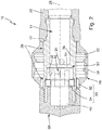
- the rotary cleaning nozzle 10 comprises a nozzle assembly 12 with a supply channel 14 for the fluid and a nozzle head 16 rotatably mounted on the nozzle assembly 12 with a nozzle outlet opening 18, from which fluid flowing in operation in the form of a cleaning jet emerges through the supply channel 14 and the nozzle head 16.
- the nozzle head 16 is actuated in a rotary manner relative to the nozzle assembly 12.
- the nozzle head 16 rotates together with the nozzle outlet opening 18 around the nozzle assembly 12, which can be fixed via a connecting sleeve 20 to a stationary fluid line in a clean room of the beverage filling system.
- the rotation of the nozzle head 16 causes fluid emerging from the nozzle outlet opening 18 to be dispensed uniformly and rotationally symmetrically.
- the rotary cleaning nozzle 10 is set up in such a way that the fluid to be supplied to the nozzle head 16 via the supply channel 14 and to flow through it actuates the nozzle head 16 in a rotary manner.
- the nozzle head 16 is designed such that when the cleaning jet is rotated, the cleaning jet is expelled from the nozzle outlet opening 18 in a direction facing away from a direction of rotation of the nozzle head 16, in particular in a direction opposite to the direction of rotation.
- the cleaning jet also has a tangential component, which thus causes a recoil and thus a rotation of the nozzle head 16.
- the nozzle head 16 comprises a feed section 22 which connects the nozzle outlet opening 18 to the feed channel 14 in a fluid-communication manner.
- the feed section 22 is designed such that fluid that can be supplied to the nozzle head 16 via the feed channel 14 is deflected in the direction of the nozzle outlet opening 18. In this way it is achieved that fluid exiting via the nozzle outlet opening 18 generates a recoil on the nozzle head 16 and this is thereby actuated in rotation.
- the rotary cleaning nozzle 10 can be set up so that a rotary drive actuates the nozzle head 16 in a rotary manner.
- the nozzle assembly 12 comprises at least one supply opening 24, which in particular connects the supply channel 14 with the nozzle head 16 connect to the feed section 22 in fluid communication.
- the supply openings 24 can be designed in the form of through openings arranged opposite one another in a side wall 26 of the nozzle assembly 12 and open into the supply channel 14.
- the nozzle assembly 12 is sleeve-shaped and provided with a cylindrical recess which is open on one side and which forms the feed channel 14 for the fluid.
- the feed channel 14 extends from an end face along an axial direction 28 of the nozzle assembly 12.
- the nozzle head 16 is annular and is pushed axially onto the nozzle assembly 12.
- the rotary cleaning nozzle 10 comprises two rotary slide bearings 29 which are arranged on ends of the nozzle head 16 which are opposite in the axial direction 28.
- the slide bearings 29 are provided with a clearance fit and can thus form a pivot bearing that is impermeable to the fluid.
- the rotary cleaning nozzle 10 further comprises an electrical generator 30 for inducing electrical energy by rotating the nozzle head 16 relative to the nozzle assembly 12.
- an electrical generator 30 for inducing electrical energy by rotating the nozzle head 16 relative to the nozzle assembly 12.
- a rotor of the generator 30 in the form of a magnetic ring 32 is arranged in the nozzle head 16, which is a stator in the form of a the nozzle coil 12 arranged induction coil 34 is aligned and rotates relative to this in operation.
- the induction coil 34 is arranged in the radial direction within the magnetic ring 32. Accordingly, the magnet ring 32 rotates around the induction coil 34 during operation.
- the induction coil 34 can be arranged in the axial direction 28 next to the magnet ring 32.
- the magnetic ring 32 comprises a magnetic rotor 36 in which a plurality of circumferentially arranged permanent magnets 38 are inserted.
- the magnetic poles which are arranged next to one another in the circumferential direction each have a different polarity.
- the generator 30 shown here is provided in the form of a claw-pole generator, in which the induction coil 34 is an annular coil embedded in a ferromagnetic cage 40.
- the cage 40 is provided on a side facing the magnetic ring 32 with a plurality of flat sections 42 spaced apart from one another in the circumferential direction.
- the flat sections 42 form so-called "claws" of the generator 30 provided as a claw pole generator, which are separated from one another in the cage 40 by gaps 44 running transversely to the direction of rotation.
- the number and position of the flat sections 42 are adapted to the number and position of the magnetic poles facing the induction coil 34.
- the number of flat sections 42 corresponds to the number of permanent magnets 38 arranged next to one another in the circumferential direction. Furthermore, the flat sections 42 are aligned relative to the permanent magnets 38 in such a way that by rotating the nozzle head 16 relative to the nozzle assembly 12, the magnetic ring 32 can be moved relative to the induction coil 34 into a position in which in each case a flat section 42 of the cage 40 faces a permanent magnet 38.
- the rotary cleaning nozzle 10 further comprises a control unit 46 for displaying a rotation of the nozzle head 16 in dependence on the induced electrical energy, which is provided by the generator 30.
- the electrical energy induced by the generator 30 is used by the control unit 46 on the one hand as an indicator for a rotation of the nozzle head 16 and thus for a proper operation of the rotary cleaning nozzle 10 and on the other hand as an energy source for its actuation.
- control unit 46 electrically conductively connected to the induction coil 34 of the generator 30 in order to supply the latter with the electrical energy induced by the generator 30.
- the rotary cleaning nozzle 10 further comprises a capacitor 48, which is connected in parallel to the control unit 46 and is electrically conductively connected to the induction coil 34 of the generator 30. In this configuration, the electrical energy induced by the generator 30 is used both to actuate the control unit 46 and to charge the capacitor 48.
- a one-way rectifier 50 in the form of a rectifier diode is arranged between the induction coil 34 and each of the control unit 46 and the capacitor 48 and is configured to supply the alternating current induced by the generator 30 to the capacitor 48 and the control unit 46 as direct current.
- the capacitor 48 serves as an energy store, which supplies the control unit 46 with electrical energy for a limited time even after the rotation of the nozzle head 16 has ended.
- the rotary cleaning nozzle 10 enables the control unit 46 to indicate whether proper operation, that is to say a rotation of the nozzle head 16, has taken place even after its operation has ended, for example after a cleaning process has ended.
- the control unit 46 is set up to be operated in an switched-on or a switched-off state depending on the electrical energy supplied to it. In When switched on, the control unit 46 displays the rotation of the nozzle head 16. In contrast, in the switched-off state, the control unit 46 does not indicate any rotation of the nozzle head.
- the control unit 46 is operated in the switched-on state when electrical energy is supplied to it either by the generator 30 and / or the capacitor 48. If, on the other hand, the supply of electrical energy is interrupted, the control unit 46 changes over to the switched-off state.
- the control unit 46 is provided here in the form of a light-emitting diode (LED) which, in response to the electrical energy induced by the generator 30, emits light in the visible wavelength range.
- LED light-emitting diode
- a glow of the control unit 46 indicates that the nozzle head 16 is rotating and thus the rotary cleaning nozzle 10 is operated properly. In this way, a simple visual inspection for a user of the beverage filling system is made possible.
- control unit 46 can be configured to emit electromagnetic radiation in the invisible wavelength range. More precisely, the control unit 46 can be set up to emit the electromagnetic radiation in the invisible wavelength range in the direction of a detector, for example a stationary monitoring unit.
- the detector can be set up to detect the electromagnetic radiation and convert it into an output signal, for example an electrical or digital output signal. The output signal can be used to indicate the state of the rotary cleaning nozzle to the user.
- the nozzle assembly 12 is provided with a further recess 52 in which the induction coil 34, the control unit 46, the capacitor 48, and the one-way rectifier 50 are arranged.
- the further recess 52 is provided as a recess open on one side, which is arranged in the nozzle block 12 opposite the feed channel 14 and is separated from it by means of a partition 54.
- the further recess 52 can be closed for the fluid-impermeable by a reclosable closure cap 56.
- an external thread is provided on an end of the nozzle assembly 12 which surrounds the further recess 52 and which is complementary to an internal thread on the closure cap 56.
- the cap 56 is made of a material that is transparent to the light emitted by the control unit 46.
- the components arranged in the further recess 52 can be arranged in the nozzle head 16, so that the induction coil forms a rotor of the generator 30, wherein the magnetic ring can be arranged in the nozzle assembly 12 and can accordingly form a stator of the generator 30.
- the control unit can be arranged together with the induction coil in or on the nozzle head 16.
- Figure 4 shows a cleaning system 58 for cleaning surfaces in a beverage filling system.
- the cleaning system 58 comprises at least one rotary cleaning nozzle 10 of a second embodiment arranged in a clean room 60 of the beverage filling system and a stationary monitoring unit 62 arranged outside of the clean room 60.
- the embodiment shown is the control unit 46 of FIG Figure 4 Rotating cleaning nozzle 10 shown configured to emit an electromagnetic signal in the form of a radio signal 64 as the signal indicating the rotation of the nozzle head 16.
- the stationary monitoring unit 62 comprises a receiver 66 for receiving the radio signal 64 to be emitted by the control unit 46 and an output unit in the form of a monitor 68 for outputting information relating to the rotation of the cleaning head 16 to a user in response to the radio signal received by the receiver 66 64. Since the control unit 46 emits the radio signal 64, the cleaning system 58 shown here enables wireless communication between the at least one rotary cleaning nozzle 10 and the stationary monitoring unit 62 of the beverage filling system.
- control unit 46 of the rotary cleaning nozzle 10 and the receiver 66 can be electrically conductively connected via a cable, wherein the control unit 46 can emit an electrical signal via the cable.
Landscapes
- Engineering & Computer Science (AREA)
- Power Engineering (AREA)
- Mechanical Engineering (AREA)
- Chemical & Material Sciences (AREA)
- Analytical Chemistry (AREA)
- Filling Of Jars Or Cans And Processes For Cleaning And Sealing Jars (AREA)
- Cleaning By Liquid Or Steam (AREA)
Abstract
Description
- Die vorliegende Erfindung betrifft eine Rotationsreinigungsdüse und ein Reinigungssystem mit einer derartigen Rotationsreinigungsdüse zum Reinigen von Oberflächen in einer Getränkeabfüllanlage, beispielsweise in einer aseptischen Getränkeabfüllanlage.
- Zur Einhaltung von Hygieneanforderungen werden bei der Verpackung von Lebensmitteln aseptische Anlagen eingesetzt, in denen Prozessgüter unter sterilen Bedingungen verarbeitet werden. Hierzu zählen beispielsweise aseptische Getränkeabfüllanlagen.
- Derartige Anlagen weisen von der Umgebung abgegrenzte Reinräume auf, die sowohl von den zu befüllenden Behältern als auch von dem Füllprodukt durchlaufen werden und in denen Behandlungsstationen zum Behandeln der Behälter angeordnet sind. Unter den Behandlungsstationen können beispielsweise Streckblasstationen zum Herstellen von zu befüllenden Behältern aus Preforms, Rinsstationen zum Rinsen der Behälter, Abfüllstationen zum Befüllen der Behälter mit einem Füllprodukt und Verschließstationen zum Verschließen der mit dem Füllprodukt befüllten Behälter sein.
- Zur Einhaltung der Hygieneanforderungen werden die Reinräume turnusgemäß oder bei Bedarfbeispielsweise nach Betriebsunterbrechungen - einer Reinigung und einer nachfolgenden Sterilisierung unterzogen. Die Reinigung erfolgt üblicherweise durch das Beaufschlagen der jeweiligen Anlagenkomponenten mit einem Reinigungsmedium, mittels dessen Produktreste abgespült werden können. Nachfolgend kann ein Desinfektionsmedium oder ein Sterilisationsmedium aufgebracht werden. Die jeweiligen Reinigungs-, Sterilisations- und/der Desinfektionsmedien werden üblicher Weise mittels in der Anlage eingebrachten Düsen auf die jeweiligen Anlagenkomponenten aufgebracht.
- Unter den Düsen zum Aufbringen der jeweiligen Reinigungs-, Sterilisations- und/der Desinfektionsmedien auf die Anlagenkomponenten sind stationäre Düsen bekannt, die unterschiedliche Sprühmuster verwenden können.
- Zum Versprühen der jeweiligen Reinigungs-, Sterilisations- und/der Desinfektionsmedien sind auch Rotationsreinigungsdüsen bekannt, welche für spezielle Anwendungen bei der Reinigung und Desinfektion in den Reinräumen eingesetzt werden. Diese Rotationsreinigungsdüsen zeichnen sich durch einen im Betrieb rotierenden Düsenkopf aus, der das jeweiligen Reinigungs-, Sterilisations- und/der Desinfektionsmedien mit einem großflächigen und rotationssymmetrischen Sprühbild auf die Anlagenkomponenten aufbringen kann. Über die Rotationsbewegung kann auch die mechanische Abreinigungskomponente verstärkt werden, da ein konzentrierter Reinigungsmedienstrahl periodisch eine vorgegebene Fläche überstreichen kann.
- Verschleißerscheinungen oder Verunreinigungen in dem jeweiligen Reinigungs-, Sterilisations- und/der Desinfektionsmedium können zu einem Ausfall oder zu einer Fehlfunktion einzelner Rotationsreinigungsdüsen führen. Dies kann sich beispielsweise darin äußern, dass die Rotation des Düsenkopfes gesperrt ist. Bei einer derartigen Fehlfunktion besteht jedoch die Gefahr, dass Anlagenoberflächen, beispielsweise Oberflächen des Reinraumgehäuses, nicht vollständig mit dem jeweiligen Medium beaufschlagt werden und somit nicht ordnungsgemäß gereinigt und/oder sterilisiert werden.
- Es besteht somit ein Bedarf an einem Überwachungssystem, das eine Fehlfunktion von Reinigungsrotationsdüsen anzeigt.
- Aus dem Stand der Technik sind kapazitive Durchflusssensoren bekannt, die in einer Zufuhrleitung stromaufwärts der Rotationsreinigungsdüse angeordnet sind und einen Durchfluss des Reinigungsmittels in Richtung der Rotationsreinigungsdüse überwachen. Eine durch Sperrung der Rotationsbewegung des Düsenkopfes hervorgerufene Fehlfunktion lässt sich durch derartige Durchflusssensoren jedoch nicht bestimmen.
- Ferner ist aus der
DE 29 18 476 A1 eine Überwachungseinrichtung für Reinigungsdüsen zur Innenreinigung von Nahrungsmitteltanks bekannt. Die Überwachungseinrichtung umfasst einen Kontaktgeber, insbesondere einen Magneten, der synchron mit der Rotationsreinigungsdüse bewegt wird und induktiv Einfluss auf einen außerhalb der Reinigungsdüse angeordneten Kontaktnehmer zum Überwachen der Drehfrequenz der Rotationsreinigungsdüse nimmt. - Ausgehend von dem bekannten Stand der Technik ist es eine Aufgabe der vorliegenden Erfindung, eine verbesserte Rotationsreinigungsdüse zum Reinigen von Oberflächen in einer Getränkeabfüllanlage bereitzustellen, deren Betrieb zuverlässig überwacht werden kann und die gleichzeitig eine modulare Bauweise aufweist. Ferner ist es eine Aufgabe der vorliegenden Erfindung, ein Reinigungssystem mit einer derartigen Rotationsreinigungsdüse bereitzustellen.
- Die Aufgaben werden durch eine Rotationsreinigungsdüse mit den Merkmalen des Anspruchs 1 und durch ein Reinigungssystem mit den Merkmalen des Anspruchs 15 gelöst. Vorteilhafte Weiterbildungen ergeben sich aus den Unteransprüchen sowie der vorliegenden Beschreibung und den Figuren.
- Entsprechend wird eine Rotationsreinigungsdüse zum Reinigen von Oberflächen einer Getränkeabfüllanlage mittels eines Fluids vorgeschlagen, umfassend einen Düsenstock mit einem Zufuhrkanal für das Fluid und einen an dem Düsenstock drehbar gelagerten Düsenkopf mit wenigstens einer Düsenaustrittsöffnung, aus der im Betrieb durch den Zufuhrkanal und den Düsenkopf strömendes Fluid in Form eines Reinigungsstrahls austritt. Ferner umfasst die Rotationsreinigungsdüse einen elektrischen Generator zum Induzieren elektrischer Energie durch Rotation des Düsenkopfes und eine Kontrolleinheit zum Anzeigen einer Rotation des Düsenkopfes in Abhängigkeit der induzierten elektrischen Energie.
- In der vorgeschlagenen Rotationsreinigungsdüse ist der elektrische Generator dazu eingerichtet, bei ordnungsgemäßem Betrieb, also bei Rotation des Düsenkopfes, durch die Rotation induzierte elektrische Energie bereitzustellen. Die derart induzierte Energie kann von der Kontrolleinheit dazu genutzt werden, eine Rotation des Düsenkopfes und somit einen ordnungsgemäßen Betrieb der Rotationsreinigungsdüse anzuzeigen. Die induzierte elektrische Energie kann jedoch nicht nur als Indikator für das Vorhandensein einer Rotation des Düsenkopfes, sondern auch zur Betätigung der Kontrolleinheit genutzt werden. Mit anderen Worten kann der elektrische Generator als Energiequelle für die Kontrolleinheit dienen. Auf diese Weise kann ein geringer Teil der kinetischen und inneren Energie des durch die Rotationsreinigungsdüse strömenden Fluids zum Betreiben der Kontrolleinheit genutzt werden. Im Allgemeinen wird eine derartige Umwandlung beziehungsweise Abzweigung kleiner Mengen elektrischer Energie für Verbraucher mit geringer Leistung aus bereits im System vorhandenen Energiequellen, wie z.B. einem Fluidstrom, auch als "Energy Harvesting" bezeichnet.
- Diese strukturelle und funktionelle Ausgestaltung ermöglicht, dass die Rotationsreinigungsdüse selbstständig, also ohne Kopplung zu Komponenten außerhalb der Rotationsreinigungsdüse, eine Fehlfunktion der Reinigungsrotationsdüse erkennen und anzeigen kann. Im Ergebnis wird somit eine Rotationsreinigungsdüse bereitgestellt, die mit einem Überwachungssystem für Fehlfunktionen ausgestattet ist und gleichzeitig einen modularen Aufbau aufweist, bei dem Abhängigkeiten und Schnittstellen zu anderen Komponenten, wie z.B. einer stationären Überwachungseinheit oder einer Stromversorgung, der Getränkeabfüllanlage minimiert sind. Dieser modulare Aufbau weist den Effekt auf, dass die vorgeschlagene Rotationsreinigungsdüse flexibel und austauschbar in gängigen Getränkeabfüllanlagen einsetzbar ist, ohne dass daraus ein hoher Anpassungsbedarf für das Gesamtsystem resultiert.
- Die vorgeschlagene Rotationsreinigungsdüse ist vorzugsweise zum Reinigen von Oberflächen in einer Getränkeabfüllanlage vorgesehen, kann jedoch in beliebigen aseptischen Anlagen oder anderen Anlagen zur Reinigung von Oberflächen zum Einsatz kommen.
- Die Reinigungswirkung der Rotationsreinigungsdüse ist auf das aus dem Düsenkopf über die Düsenaustrittsöffnung austretende Fluid zurückzuführen. Das Fluid kann gasförmig oder flüssig sein. Vorzugsweise ist das Fluid ein Reinigungsmittel, das eine die Reinigung begünstigende chemische Struktur aufweist. Beispielsweise kann das Fluid ein Mittel zur Sterilisierung der Oberflächen sein, ein sogenannter Sterilisator. Entsprechend kann das Fluid beispielsweise Wasserstoffperoxid (H2O2) oder Peressigsäure umfassen.
- Um im Betrieb ein großflächiges und gleichmäßiges Beaufschlagen der zu reinigenden Oberflächen mittels des Fluids sicherzustellen, kann der Düsenkopf relativ zu dem Düsenstock rotatorisch betätigt werden. Hierzu kann die Rotationsreinigungsdüse derart eingerichtet sein, dass das dem Düsenkopf im Betrieb über den Zufuhrkanal zuzuführende und diesen zu durchströmende Fluid den Düsenkopf rotatorisch betätigt. Genauer kann das Fluid beim Durchströmen des Düsenkopfs eine Kraft, insbesondere eine Rückstoßkraft, auf den Düsenkopf ausüben, die ein Drehmoment und somit die Rotation des Düsenkopfes bewirkt. Mit anderen Worten, indem das Fluid durch den Düsenkopf strömt, erfährt dieser einen Rückstoß und wird so rotatorisch betätigt.
- Zum Erzeugen der den Düsenkopf rotatorisch betätigenden Kraft kann der Düsenkopf dazu ausgebildet sein, bei rotatorischer Betätigung den Reinigungsstrahl in einer von einer Rotationsrichtung des Düsenkopfes abgewandten Richtung, insbesondere einer zu der Rotationsrichtung entgegengesetzten Richtung, aus der Düsenaustrittsöffnung auszustoßen. Ferner kann der Düsenkopf derart ausgebildet sein, dass das Fluid beim Durchströmen desselben umgelenkt wird. Entsprechend kann der Düsenkopf mit wenigstens einem Zufuhrabschnitt versehen sein, der dem Düsenkopf über den Zufuhrkanal zuführbares Fluid in Richtung der Düsenaustrittsöffnung umlenkt.
- Alternativ oder zusätzlich kann die Rotationsreinigungsdüse derart eingerichtet sein, dass ein Rotationsantrieb den Düsenkopf rotatorisch betätigt. Der Rotationsantrieb kann beispielsweise ein Elektromotor sein.
- Um den Düsenkopf an dem Düsenstock drehbar zu lagern, kann wenigstens ein Gleitlager, insbesondere ein rotatorisches Gleitlager, zwischen dem Düsenkopf und dem Düsenstock vorgesehen sein. Das Gleitlager kann mit einer Spielpassung versehen sein.
- Der Düsenstock kann hülsenförmig ausgebildet sein. Entsprechend kann der Düsenkopf ringförmig ausgebildet und axial auf den Düsenstock aufgeschoben sein. In dieser Ausgestaltung kann in axialer Richtung des Düsenstocks an entgegengesetzten Enden des Düsenkopfes jeweils ein Gleitlager vorgesehen sein, zwischen denen der wenigstens eine Zufuhrabschnitt des Düsenkopfes und die wenigstens eine Zufuhröffnung des Düsenstocks angeordnet sein können.
- Der Düsenstock kann mit einer einseitig geöffneten Ausnehmung versehen seien, die den Zufuhrkanal für das Fluid bildet. Der Zufuhrkanal erstreckt sich vorzugsweise entlang einer axialen Richtung des Düsenstocks. Die als Zufuhrkanal ausgebildete Ausnehmung kann zylinderförmig ausgebildet sein. In die Ausnehmung kann die wenigstens eine Zufuhröffnung münden. Die Zufuhröffnung kann in Form einer Durchgangsöffnung in einer Seitenwand des Düsenstocks ausgebildet sein und sich insbesondere entlang einer radialen Richtung des Düsenstocks erstrecken. Der Düsenstock kann eine Vielzahl von Zufuhröffnungen aufweisen, die in Umfangsrichtung des Düsenstocks in regelmäßigen Abständen zueinander ausgebildet sein können. Beispielsweise kann der Düsenstock in dessen Seitenwand zwei gegenüberliegend zueinander angeordnete Zufuhröffnungen aufweisen.
- Zum Induzieren elektrischer Energie durch Rotation des Düsenkopfes umfasst die Rotationsreinigungsdüse den elektrischen Generator. Im Allgemeinen wird unter einem elektrischen Generator eine Vorrichtung zum Umwandeln von kinetischer in elektrische Energie mittels elektromagnetischer Induktion verstanden. Der grundlegende Aufbau eines elektrischen Generators ist dem Fachmann aus dem Stand der Technik bekannt und ist hier nicht im Detail beschrieben. Im Nachstehenden wird daher lediglich auf Besonderheiten der hier offenbarten Rotationsreinigungsdüse eingegangen.
- Der Generator in der Rotationsreinigungsdüse kann einen an oder in dem Düsenkopf angeordneten Rotor und einen dazu ausgerichteten, an oder in dem Düsenstock angeordneten Stator umfassen. Vorliegend wird unter einem Stator ein feststehendes Bauteil des Generators verstanden. Entsprechend wird unter einem Rotor ein bewegliches, insbesondere rotierendes, Bauteil des Generators verstanden. In einer Ausführungsform kann der Rotor in Form wenigstens eines Magneten und der Stator in Form wenigstens einer Induktionsspule bereitgestellt sein. Alternativ kann der Rotor in Form wenigstens einer Induktionsspule und der Stator in Form wenigstens eines Magneten bereitgestellt sein.
- Beispielsweise können der Düsenkopf mit dem Magneten und der Düsenstock mit der Induktionsspule bereitgestellt sein. In dieser Ausführungsform kann die Kontrolleinheit zusammen mit der Induktionsspule in oder an dem Düsenstock angeordnet sein. Alternativ oder zusätzlich, können der Düsenkopf mit der Induktionsspule und der Düsenstock mit dem Magneten bereitgestellt sein. In dieser Ausführungsform kann die Kontrolleinheit zusammen mit der Induktionsspule in oder an dem Düsenkopf angeordnet sein.
- Der Magnet umfasst vorzugsweise wenigstens einen Permanentmagneten. Entsprechend der Ausgestaltung des Düsenkopfes oder des Düsenstocks kann der Magnet ein aus mehreren Permanentmagneten aufgebauter Magnetring sein, umfassend eine Vielzahl umlaufend nebeneinander angeordneter Magnetpole. Dabei weisen jeweils in Umlaufrichtung nebeneinander angeordnete Magnetpole vorzugsweise eine unterschiedliche Polung auf.
- Die Induktionsspule kann als Ringspule mit einer Vielzahl von Wicklungen bereitgestellt sein. In einer Weiterentwicklung kann der Generator in Form eines sogenannten Klauenpolgenerators bereitgestellt sein, bei dem die Ringspule in einem ferromagnetischen Käfig oder einer ferromagnetischen Ummantelung eingebettet ist. Der Käfig kann derart bereitgestellt sein, dass an einer dem Magneten, insbesondere dem Magnetring, zugewandten Seite dieser mit einer Vielzahl in Umlaufrichtung voneinander beabstandeter, flächiger Abschnitte versehen ist. Mit anderen Worten, an einer dem Magneten zugewandten Seite weist der Käfig in Umlaufrichtung zwischen den flächigen Abschnitten Spalte auf, die sich im Wesentlichen entlang der gesamten Breite des Käfigs in einer Richtung quer zur Umlaufrichtung erstrecken. Diese in Umlaufrichtung voneinander beabstandeten, flächigen Abschnitte werden auch als sogenannte "Klauen" bezeichnet.
- Die Anzahl und Position der flächigen Abschnitte sind vorzugsweise an die Anzahl und Position der zu der Ringspule zugewandten Magnetpole des Magneten angepasst. Vorzugsweise entspricht die Anzahl der flächigen Abschnitte der Anzahl der Magnetpole des Magneten. Die flächigen Abschnitte sind dabei vorzugsweise relativ zu den Magnetpolen des Magneten ausgerichtet. Mit anderen Worten, durch Rotieren des Düsenkopfes relativ zu dem Düsenstock kann der Magnet relativ zu dem Käfig und der darin eingebetteten Ringspule derart positionierbar sein, dass jeweils ein flächiger Abschnitt des Käfigs jeweils einem Magnetpol des Magnetrings zugewandt ist.
- Diese als Klauenpolgenerator vorgeschlagene Ausgestaltung des Generators weist den Effekt auf, dass sich hohe Spannungen und Ströme bei einer vergleichsweise kompakten Bauweise des Generators induzieren lassen. Mit anderen Worten, auf diese Weise lässt sich ein kompakter und zugleich leistungsfähiger Generator in der Rotationsreinigungsdüse realisieren.
- Der Generator, insbesondere die Induktionsspule, ist vorzugsweise mit der Kontrolleinheit elektrisch leitend verbunden, um der Kontrolleinheit die durch den Generator induzierte elektrische Energie zuzuführen. Die Kontrolleinheit kann entsprechend dazu eingerichtet sein, eine Rotation des Düsenkopfes anzuzeigen, wenn dieser vom Generator induzierte elektrische Energie zugeführt wird. Die von dem Generator induzierte elektrische Energie kann zum Betreiben der Kontrolleinheit genutzt werden. Beispielsweise kann die Kontrolleinheit in Abhängigkeit der von dem Generator zugeführten elektrischen Energie in einem eingeschalteten und einem ausgeschalteten Zustand betrieben werden. Genauer kann die Kontrolleinheit in dem eingeschalteten Zustand betrieben werden, in dem eine Rotation des Düsenkopfes angezeigt wird, wenn der Kontrolleinheit von dem Generator elektrische Energie zugeführt wird. Entsprechend kann die Kontrolleinheit in dem ausgeschalteten Zustand betrieben werden, in dem eine Rotation des Düsenkopfes nicht angezeigt wird, wenn die Zufuhr elektrischer Energie unterbrochen wird.
- Weiterhin kann die Rotationsreinigungsdüse dazu eingerichtet sein, die von dem Generator induzierte elektrische Energie der Kontrolleinheit in Form von Gleichstrom oder Wechselstrom zuzuführen. Beispielsweise kann der elektrische Generator zum Induzieren von Wechselstrom eingerichtet sein, wobei zwischen dem Generator und der Kontrolleinheit ein an die Rotation des Düsenkopfes gekoppelter Kommutator oder ein Gleichrichter, beispielsweise ein Brückengleichrichter oder ein Einweggleichrichter, zwischengeschaltet sein kann. Auf diese Weise kann der Kontrolleinheit die von dem Generator induzierte elektrische Energie in Form von Gleichstrom zugeführt werden.
- In einer Weiterentwicklung kann die Rotationsreinigungsdüse einen Energiespeicher, insbesondere in Form eines Kondensators, umfassen. Der Energiespeicher ist vorzugsweise mit dem Generator, insbesondere der Induktionsspule, elektrisch leitend verbunden. Entsprechend kann der Energiespeicher durch die von dem Generator induzierte elektrische Energie aufladbar sein. Die Rotationsreinigungsdüse kann derart ausgebildet sein, dass von dem Generator induzierte Energie in Form von Gleichstrom dem Energiespeicher zuführbar ist. Hierzu kann in der elektrischen Verbindung zwischen dem Energiespeicher und dem Generator, insbesondere der Induktionsspule, ein an die Rotation des Düsenkopfes gekoppelter Kommutator oder ein Gleichrichter, beispielsweise ein Brückengleichrichter oder ein Einweggleichrichter, vorgesehen sein. Der elektrische Energiespeicher kann weiterhin elektrisch leitend mit der Kontrolleinheit verbunden und dazu eingerichtet sein, die darin gespeicherte elektrische Energie der Kontrolleinheit zuzuführen.
- Die Verwendung des Energiespeichers ermöglicht, dass die Kontrolleinheit eine Rotation des Düsenkopfes in einem Zustand anzeigen kann, in dem der Düsenkopf nicht länger rotiert und somit keine elektrische Energie induziert. Auf diese Weise ermöglicht die Rotationsreinigungsdüse, dass auch nach Beendigung ihres Betriebs, beispielsweise nach Beendigung eines Reinigungsvorgangs, die Kontrolleinheit anzeigen kann, ob ein ordnungsgemäßer Betrieb, also eine Rotation des Düsenkopfes, stattgefunden hat. Dies ist besonders hilfreich, wenn eine Inspektion der Rotationsreinigungsdüse nach Beendigung ihres Betriebs, beispielsweise nach Beendigung eines Reinigungsvorgangs, erfolgt.
- Zum Anzeigen der Rotation des Düsenkopfes kann die Kontrolleinheit in Form eines Emitters bereitgestellt sein, der in Erwiderung auf die durch den Generator induzierte elektrische Energie ein Signal emittiert. Mit anderen Worten, die Kontrolleinheit kann dazu eingerichtet sein, in Erwiderung auf die durch den Generator induzierte elektrische Energie ein die Rotation des Düsenkopfes anzeigendes Signal zu emittieren. Insbesondere kann die Kontrolleinheit dazu eingerichtet sein, das die Rotation des Düsenkopfes anzeigende Signal in einem Zustand, insbesondere in dem eingeschalteten Zustand, zu emittieren, in dem der Kontrolleinheit elektrische Energie von dem Generator oder dem Energiespeicher zugeführt wird.
- Das die Rotation des Düsenkopfes anzeigende Signal kann ein elektromagnetisches Signal, insbesondere Licht oder ein Funksignal, und/oder ein elektrisches Signal sein. Ferner kann die Kontrolleinheit dazu eingerichtet sein, mit einem das Signal empfangenden Empfänger zusammen zu wirken. Der Empfänger kann mit einer stationären Überwachungseinheit der Getränkeabfüllanlage verbunden sein, die das empfangene Signal verarbeitet und für einen Benutzer der Getränkeabfüllanlage visuell, beispielsweise auf einem Monitor, darstellt.
- Durch Emittieren eines elektromagnetischen Signals kann die Kontrolleinheit mit dem Empfänger und entsprechend mit der stationären Überwachungseinheit kabellos kommunizieren. Alternativ oder zusätzlich kann die Kontrolleinheit ein elektrisches Signal emittieren, dass über eine Kabelverbindung an den Empfänger und entsprechend an die stationäre Überwachungseinheit übertragbar sein kann.
- Das Emittieren von Licht als das die Rotation des Düsenkopfes anzeigende Signal ermöglicht eine einfache visuelle Inspektion für Benutzer der Getränkeabfüllanlage, um einen ordnungsgemäßen Betrieb der Rotationsreinigungsdüse festzustellen. Beispielsweise kann die Kontrolleinheit eine Lichtquelle sein oder umfassen, insbesondere eine Leuchtdiode, die von dem Generator oder dem Energiespeicher bereitgestellte elektrische Energie zum Emittieren von Licht nutzt. Hierbei kann ein Leuchten der Lichtquelle einen ordnungsgemäßen Betrieb der Rotationsreinigungsdüse anzeigen. Entsprechend kann ein Benutzer der Getränkeabfüllanlage eine Fehlfunktion der Rotationsreinigungsdüse feststellen, wenn ein Leuchten der Lichtquelle ausbleibt.
- In einer Weiterentwicklung kann die Kontrolleinheit mit der Induktionsspule verbunden und zusammen mit dieser in oder an dem Düsenkopf oder Düsenstock angeordnet sein. Entsprechend kann der Düsenkopf oder der Düsenstock aus einem für das von der Kontrolleinheit emittierte Signal durchlässigen Material hergestellt sein. Beispielsweise kann die Kontrolleinheit in einer weiteren Ausnehmung in dem Düsenstock angeordnet sein. Die weitere Ausnehmung kann mittels einer Verschlusskappe, insbesondere mittels einer wiederverschließbaren Verschlusskappe, für das fluide undurchlässig, beispielsweise luft- und/oder wasserdicht, verschlossen sein. Die Verschlusskappe kann aus einem für das von der Kontrolleinheit emittierte Signal durchlässigen Material hergestellt sein.
- Weiterhin wird ein Reinigungssystem zum Reinigen von Oberflächen in einer Getränkeabfüllanlage bereitgestellt. Das Reinigungssystem umfasst die wenigstens eine voranstehend offenbarte Rotationsreinigungsdüse und die voranstehend offenbarte stationäre Überwachungseinheit. Die stationäre Überwachungseinheit ist zum Empfangen des von der Kontrolleinheit der Rotationsreinigungsdüse zu emittierenden, eine Rotation der Rotationsreinigungsdüse anzeigenden Signals und zum Ausgeben einer die Rotation betreffenden Information in Erwiderung auf das empfangene Signal eingerichtet.
- Die stationäre Überwachungseinheit kann eine zentrale Überwachungseinheit der Getränkeabfüllanlage darstellen und umfasst vorzugsweise eine Ausgabeeinheit, beispielsweise einen Monitor, über den die Rotation des Düsenkopfes betreffende Informationen für einen Benutzer ausgegeben werden.
- Bevorzugte weitere Ausführungsformen der Erfindung werden durch die nachfolgende Beschreibung der Figuren näher erläutert. Dabei zeigen schematisch:
- Figur 1
- eine Seitenansicht auf eine Rotationsreinigungsdüse einer ersten Ausführungsform;
- Figur 2
- die Rotationsreinigungsdüse der ersten Ausführungsform in einer Längsschnittansicht;
- Figur 3
- eine perspektivische Ansicht auf einen elektrischen Generator der in
Figuren 1 und2 gezeigten Rotationsreinigungsdüse; und - Figur 4
- ein Reinigungssystem mit einer Rotationsreinigungsdüse einer zweiten Ausführungsform.
- Im Folgenden werden bevorzugte Ausführungsbeispiele anhand der Figuren beschrieben. Dabei werden gleiche, ähnliche oder gleichwirkende Elemente in den unterschiedlichen Figuren mit identischen Bezugszeichen versehen, und auf eine wiederholte Beschreibung dieser Elemente wird teilweise verzichtet, um Redundanzen zu vermeiden.
- In
Figuren 1 und2 ist schematisch eine Rotationsreinigungsdüse 10 gezeigt, die zur Reinigung von Oberflächen in einer Getränkeabfüllanlage vorgesehen ist. Die Reinigung erfolgt mittels eines durch die Rotationsreinigungsdüse 10 zu versprühenden Fluids, insbesondere in Form eines Reinigungsmittels. Die gezeigte Rotationsreinigungsdüse 10 kann flexibel für unterschiedliche Fluide, insbesondere gasförmige oder flüssige Reinigungsmittel, eingesetzt werden. Die Rotationsreinigungsdüse 10 kann entsprechend dazu eingesetzt werden, die jeweiligen Reinigungs-, Sterilisations- und/der Desinfektionsmedien in einer Reinigungs- und/oder Sterilisationssequenz eines Reinigungsprogramms in einer Getränkeabfüllanlage vorgesehen sein. - Wie in
Figur 2 gezeigt, umfasst die Rotationsreinigungsdüse 10 einen Düsenstock 12 mit einem Zufuhrkanal 14 für das Fluid und einen an dem Düsenstock12 drehbar gelagerten Düsenkopf 16 mit einer Düsenaustrittsöffnung 18, aus der im Betrieb durch den Zufuhrkanal 14 und den Düsenkopf 16 strömendes Fluid in Form eines Reinigungsstrahls austritt. Um im Betrieb ein großflächiges und gleichmäßiges Besprühen der zu reinigenden Oberflächen mittels des Fluids sicherzustellen und auch um eine weitere mechanische Abreinigungskomponente bereit zu stellen, wird der Düsenkopf 16 relativ zu dem Düsenstock 12 rotatorisch betätigt. Mit anderen Worten, im Betrieb rotiert der Düsenkopf 16 zusammen mit der Düsenaustrittsöffnung 18 um den Düsenstock 12, der über eine Verbindungsmuffe 20 fest an einer stationären Fluidleitung in einem Reinraum der Getränkeabfüllanlage befestigbar ist. Die Rotation des Düsenkopfes 16 bewirkt, dass aus der Düsenaustrittsöffnung 18 austretendes Fluid gleichmäßig und rotationssymmetrisch ausgegeben wird. - Genauer ist die Rotationsreinigungsdüse 10 derart eingerichtet, dass das dem Düsenkopf 16 über den Zufuhrkanal 14 zuzuführende und diesen zu durchströmende Fluid den Düsenkopf 16 rotatorisch betätigt. Hierzu ist der Düsenkopf 16 derart ausgebildet, dass bei rotatorischer Betätigung der Reinigungsstrahl in einer von einer Rotationsrichtung des Düsenkopfes 16 abgewandten Richtung, insbesondere einer zu der Rotationsrichtung entgegengesetzten Richtung, aus der Düsenaustrittsöffnung 18 ausgestoßen wird. Mit anderen Worten weist der Reinigungsstrahl auch eine tangentiale Komponente auf, die damit einen Rückstoß und damit eine Rotation des Düsenkopfs 16 hervorruft. Der Düsenkopf 16 umfasst einen Zufuhrabschnitt 22, der die Düsenaustrittsöffnung 18 fluidkommunikativ mit dem Zufuhrkanal 14 verbindet. Der Zufuhrabschnitt 22 ist derart ausgebildet, dass dem Düsenkopf 16 über den Zufuhrkanal 14 zuführbares Fluid in Richtung der Düsenaustrittsöffnung 18 umgelenkt wird. Auf diese Weise wird erreicht, dass über die Düsenaustrittsöffnung 18 austretendes Fluid einen Rückstoß an dem Düsenkopf 16 erzeugt und dieser dadurch rotatorisch betätigt wird. Alternativ oder zusätzlich kann die Rotationsreinigungsdüse 10 dazu eingerichtet sein, dass ein Rotationsantrieb den Düsenkopf 16 rotatorisch betätigt.
- Zum Zuführen des Fluids aus dem Zufuhrkanal 14 in den Düsenkopf 16 umfasst der Düsenstock 12 mindestens eine Zufuhröffnung 24, die den Zufuhrkanal 14 mit dem Düsenkopf 16, insbesondere mit dem Zufuhrabschnitt 22, fluidkommunikativ verbinden. Die Zufuhröffnungen 24 können in Form von in einer Seitenwand 26 des Düsenstocks 12 gegenüberliegend angeordneten Durchgangsöffnungen ausgebildet sein, die in den Zufuhrkanal 14 münden.
- Der Düsenstock 12 ist hülsenförmig ausgebildet und mit einer einseitig geöffneten, zylindrischen Ausnehmung versehen, die den Zufuhrkanal 14 für das Fluid bildet. Der Zufuhrkanal 14 erstreckt sich von einer Stirnfläche entlang einer axialen Richtung 28 des Düsenstocks 12. Der Düsenkopf 16 ist ringförmig ausgebildet und axial auf den Düsenstock 12 aufgeschoben. Zur drehbaren Lagerung des Düsenkopfes 16 relativ zu dem Düsenstock 12 umfasst die Rotationsreinigungsdüse 10 zwei rotatorische Gleitlager 29, die an in axialer Richtung 28 entgegengesetzten Enden des Düsenkopfes 16 angeordnet sind. Die Gleitlager 29 sind mit einer Spielpassung versehen und können so ein für das Fluid undurchlässiges Drehlager bilden.
- Die Rotationsreinigungsdüse 10 umfasst ferner einen elektrischen Generator 30 zum Induzieren elektrischer Energie durch Rotation des Düsenkopfes 16 relativ zu dem Düsenstock 12. Hierzu ist ein Rotor des Generators 30 in Form eines Magnetrings 32 in dem Düsenkopf 16 angeordnet, der zu einem Stator in Form einer in dem Düsenstock 12 angeordneten Induktionsspule 34 ausgerichtet ist und im Betrieb relativ zu diesem rotiert. In der hier gezeigten Ausführungsform ist die Induktionsspule 34 in radialer Richtung innerhalb des Magnetrings 32 angeordnet. Entsprechend rotiert der Magnetring 32 im Betrieb um die Induktionsspule 34. Alternativ kann die Induktionsspule 34 in axialer Richtung 28 neben dem Magnetring 32 angeordnet sein.
- Wie in
Figur 3 gezeigt, umfasst der Magnetring 32 einen Magnetläufer 36 in dem eine Vielzahl von umlaufend nebeneinander angeordneten Permanentmagneten 38 eingesetzt sind. Wie in der Figur durch die eine Polung der Permanentmagneten 38 kennzeichnenden Buchstaben "N" und "S" angezeigt, weisen jeweils in Umlaufrichtung nebeneinander angeordnete Magnetpole eine unterschiedliche Polung auf. - Der hier gezeigte Generator 30 ist in Form eines Klauenpolgenerators bereitgestellt, bei dem die Induktionsspule 34 eine in einem ferromagnetischen Käfig 40 eingebettete Ringspule ist. Der Käfig 40 ist an einer dem Magnetring 32 zugewandten Seite mit einer Vielzahl in Umlaufrichtung voneinander beabstandeter, flächiger Abschnitte 42 versehen. Die flächigen Abschnitte 42 bilden sogenannte "Klauen" des als Klauenpolgenerators bereitgestellten Generators 30, die in dem Käfig 40 jeweils voneinander durch quer zur Umlaufrichtung verlaufende Spalte 44 getrennt sind.
- Die Anzahl und Position der flächigen Abschnitte 42 sind an die Anzahl und Position der zu der Induktionsspule 34 zugewandten Magnetpole angepasst. In der hier gezeigten Konfiguration entspricht die Anzahl der flächigen Abschnitte 42 der Anzahl der in Umlaufrichtung nebeneinander angeordneten Permanentmagneten 38. Ferner sind die flächigen Abschnitte 42 relativ zu den Permanentmagneten 38 derart ausgerichtet, dass durch Rotieren des Düsenkopfes 16 relativ zu dem Düsenstock 12 der Magnetring 32 relativ zu der Induktionsspule 34 in eine Position bewegt werden kann, in der jeweils ein flächiger Abschnitt 42 des Käfigs 40 einem Permanentmagneten 38 zugewandt ist.
- Die Rotationsreinigungsdüse 10 umfasst ferner eine Kontrolleinheit 46 zum Anzeigen einer Rotation des Düsenkopfes 16 in Abhängigkeit der induzierten elektrischen Energie, die durch den Generator 30 bereitgestellt wird. Die von dem Generator 30 induzierte elektrische Energie wird von der Kontrolleinheit 46 zum einen als Indikator für eine Rotation des Düsenkopfes 16 und somit für einen ordnungsgemäßen Betrieb der Rotationsreinigungsdüse 10 und zum anderen als Energiequelle für deren Betätigung genutzt.
- Hierzu ist die Kontrolleinheit 46, wie in
Figur 2 gezeigt, elektrisch leitend mit der Induktionsspule 34 des Generators 30 verbunden, um dieser die durch den Generator 30 induzierte elektrische Energie zuzuführen. Die Rotationsreinigungsdüse 10 umfasst ferner einen Kondensator 48, der parallel zu der Kontrolleinheit 46 geschaltet und mit der Induktionsspule 34 des Generators 30 elektrisch leitend verbunden ist. In dieser Konfiguration wird die von dem Generator 30 induzierte elektrische Energie sowohl zum Betätigen der Kontrolleinheit 46 als auch zum Aufladen des Kondensators 48 genutzt. Wie inFigur 2 gezeigt, ist zwischen der Induktionsspule 34 und jeweils der Kontrolleinheit 46 und dem Kondensator 48 ein Einweggleichrichter 50 in Form einer Gleichrichterdiode angeordnet, der dazu eingerichtet ist, den von dem Generator 30 induzierten Wechselstrom dem Kondensator 48 und der Kontrolleinheit 46 als Gleichstrom zuzuführen. - Der Kondensator 48 dient als Energiespeicher, der der Kontrolleinheit 46 auch nach Ende der Rotation des Düsenkopfes 16 für eine begrenzte Zeit elektrische Energie zuführt. Auf diese Weise ermöglicht die Rotationsreinigungsdüse 10, dass auch nach Beendigung ihres Betriebs, beispielsweise nach Beendigung eines Reinigungsvorgangs, die Kontrolleinheit 46 anzeigen kann, ob ein ordnungsgemäßer Betrieb, also eine Rotation des Düsenkopfes 16, stattgefunden hat.
- Die Kontrolleinheit 46 ist dazu eingerichtet, in Abhängigkeit der dieser zugeführten elektrischen Energie in einem eingeschalteten oder einem ausgeschalteten Zustand betrieben zu werden. In dem eingeschalteten Zustand zeigt die Kontrolleinheit 46 die Rotation des Düsenkopfes 16 an. In dem ausgeschalteten Zustand wird hingegen durch die Kontrolleinheit 46 keine Rotation des Düsenkopfes angezeigt. Die Kontrolleinheit 46 wird dann in dem eingeschalteten Zustand betrieben, wenn dieser elektrische Energie entweder durch den Generator 30 und/oder den Kondensator 48 zugeführt wird. Wird hingegen die Zufuhr elektrischer Energie unterbrochen, geht die Kontrolleinheit 46 in den ausgeschalteten Zustand über.
- Die Kontrolleinheit 46 ist hier in Form einer Leuchtdiode (LED) bereitgestellt, die in Erwiderung auf die durch den Generator 30 induzierte elektrische Energie Licht im sichtbaren Wellenlängenbereich emittiert. Mit anderen Worten, in dieser Konfiguration zeigt ein Leuchten der Kontrolleinheit 46 an, dass der Düsenkopf 16 rotiert und somit die Rotationsreinigungsdüse 10 ordnungsgemäß betrieben wird. Auf diese Weise wird eine einfache visuelle Inspektion für einen Benutzer der Getränkeabfüllanlage ermöglicht.
- Alternativ oder zusätzlich kann die Kontrolleinheit 46 dazu eingerichtet sein, elektromagnetische Strahlung im nichtsichtbaren Wellenlängenbereich zu emittieren. Genauer kann die Kontrolleinheit 46 dazu eingerichtet sein, die elektromagnetische Strahlung im nichtsichtbaren Wellenlängenbereich in Richtung eines Detektors, beispielsweise einer stationären Überwachungseinheit zu emittieren. Hierbei kann der Detektor dazu eingerichtet sein, die elektromagnetische Strahlung zu detektieren und in ein Ausgabesignal, beispielsweise ein elektrisches oder digitales Ausgabesignal, umzuwandeln. Das Ausgabesignal kann dabei dazu dienen, dem Benutzer den Zustand der Rotationsreinigungsdüse anzuzeigen.
- Der Düsenstock 12 ist mit einer weiteren Ausnehmung 52 versehen, in der die Induktionsspule 34, die Kontrolleinheit 46, der Kondensator 48, und der Einweggleichrichter 50 angeordnet sind. Die weitere Ausnehmung 52 ist als eine einseitig geöffnete Ausnehmung bereitgestellt, die in dem Düsenstock 12 gegenüberliegend zu dem Zufuhrkanal 14 angeordnet und von diesem mittels einer Trennwand 54 getrennt ist. Die weitere Ausnehmung 52 ist über eine wiederverschließbare Verschlusskappe 56 für das fluidundurchlässig verschließbar. Hierfür ist an einem die weitere Ausnehmung 52 umschließenden Ende des Düsenstocks 12 ein Außengewinde vorgesehen, dass komplementär zu einem Innengewinde an der Verschlusskappe 56 ausgebildet ist. Die Verschlusskappe 56 ist aus einem Material hergestellt, das für das von der Kontrolleinheit 46 emittierte Licht durchlässig ist.
- In einer alternativen Ausführungsform können die in der weiteren Ausnehmung 52 angeordneten Komponenten in dem Düsenkopf 16 angeordnet sein, sodass die Induktionsspule einen Rotor des Generators 30 bildet, wobei der Magnetring in dem Düsenstock 12 angeordnet sein kann und entsprechend einen Stator des Generators 30 bilden kann. Entsprechend kann die Kontrolleinheit zusammen mit der Induktionsspule in oder an dem Düsenkopf 16 angeordnet sein.
-
Figur 4 zeigt ein Reinigungssystem 58 zum Reinigen von Oberflächen in einer Getränkeabfüllanlage. Das Reinigungssystem 58 umfasst wenigstens eine in einem Reinraum 60 der Getränkeabfüllanlage angeordnete Rotationsreinigungsdüse 10 einer zweiten Ausführungsform und eine außerhalb des Reinraums 60 angeordnete stationäre Überwachungseinheit 62. - Gegenüber der in
Figuren 1 bis 3 gezeigten Ausführungsform ist die Kontrolleinheit 46 der inFigur 4 gezeigten Rotationsreinigungsdüse 10 dazu eingerichtet, ein elektromagnetisches Signal in Form eines Funksignals 64 als das die Rotation des Düsenkopfes 16 anzeigende Signal zu emittieren. Die stationäre Überwachungseinheit 62 umfasst einen Empfänger 66 zum Empfangen des von der Kontrolleinheit 46 zu emittierenden Funksignals 64 und eine Ausgabeeinheit in Form eines Monitors 68 zum Ausgeben einer die Rotation des Reinigungskopfes 16 betreffenden Information für einen Benutzer in Erwiderung auf das durch den Empfänger 66 empfangene Funksignal 64. Indem die Kontrolleinheit 46 das Funksignal 64 emittiert, ermöglicht das hier gezeigte Reinigungssystem 58 eine kabellose Kommunikation zwischen der wenigstens einen Rotationsreinigungsdüse 10 und der stationären Überwachungseinheit 62 der Getränkeabfüllanlage. - Alternativ können die Kontrolleinheit 46 der Rotationsreinigungsdüse 10 und der Empfänger 66 über ein Kabel elektrisch leitend verbunden sein, wobei die Kontrolleinheit 46 ein elektrisches Signal über das Kabel emittieren kann.
- Soweit anwendbar, können alle einzelnen Merkmale, die in den Ausführungsbeispielen dargestellt sind, miteinander kombiniert und/oder ausgetauscht werden, ohne den Bereich der Erfindung zu verlassen.
-
- 10
- Rotationsreinigungsdüse
- 12
- Düsenstock
- 14
- Zufuhrkanal
- 16
- Düsenkopf
- 18
- Düsenaustrittsöffnung
- 20
- Verbindungsmuffe
- 22
- Zufuhrabschnitt
- 24
- Zufuhröffnung
- 26
- Seitenwand
- 28
- axiale Richtung
- 30
- Generator
- 32
- Magnetring
- 34
- Induktionsspule
- 36
- Magnetläufer
- 38
- Permanentmagnet
- 40
- ferromagnetischer Käfig
- 42
- flächiger Abschnitt
- 44
- Spalt
- 46
- Kontrolleinheit
- 48
- Kondensator
- 50
- Einweggleichrichter
- 52
- weitere Ausnehmung
- 54
- Trennwand
- 56
- Verschlusskappe
- 58
- Reinigungssystem
- 60
- Reinraum einer Getränkeabfüllanlage
- 62
- stationäre Überwachungseinheit
- 64
- Funksignal
- 66
- Empfänger
- 68
- Monitor
Claims (15)
- Rotationsreinigungsdüse (10) zum Reinigen von Oberflächen einer Getränkeabfüllanlage mittels eines Fluids, umfassend:- einen Düsenstock (12) mit einem Zufuhrkanal (14) für das Fluid,- einen an dem Düsenstock (12) drehbar gelagerten Düsenkopf (16) mit wenigstens einer Düsenaustrittsöffnung (18), aus der im Betrieb durch den Zufuhrkanal (14) und den Düsenkopf (16) strömendes Fluid in Form eines Reinigungsstrahls austritt,- einen elektrischen Generator (30) zum Induzieren elektrischer Energie durch Rotation des Düsenkopfes (16), und- eine Kontrolleinheit (46) zum Anzeigen einer Rotation des Düsenkopfes (16) in Abhängigkeit der induzierten elektrischen Energie.
- Rotationsreinigungsdüse nach Anspruch 1, dadurch gekennzeichnet, dass das dem Düsenkopf (16) im Betrieb über den Zufuhrkanal (14) zuzuführende und diesen zu durchströmende Fluid den Düsenkopf (16) rotatorisch betätigt und/oder ein Rotationsantrieb den Düsenkopf (16) rotatorisch betätigt.
- Rotationsreinigungsdüse nach Anspruch 1 oder 2, dadurch gekennzeichnet, dass der Düsenkopf (16) dazu ausgebildet ist, bei rotatorischer Betätigung den Reinigungsstrahl in einer von einer Rotationsrichtung des Düsenkopfes (16) abgewandten Richtung, insbesondere einer zu der Rotationsrichtung entgegengesetzten Richtung, aus der Düsenaustrittsöffnung (18) auszustoßen.
- Rotationsreinigungsdüse nach Anspruch 1 bis 3, dadurch gekennzeichnet, dass der Düsenkopf (16) mit wenigstens einem Zufuhrabschnitt (22) versehen ist, der dem Düsenkopf (16) über den Zufuhrkanal (14) zuführbares Fluid in Richtung der Düsenaustrittsöffnung (18) umlenkt.
- Rotationsreinigungsdüse nach einem der Ansprüche 1 bis 4, dadurch gekennzeichnet, dass der Düsenstock (12) wenigstens eine Zufuhröffnung (24) aufweist, die den Zufuhrkanal (14) mit dem Düsenkopf (16), insbesondere mit dessen Zufuhrabschnitt (22), fluidkommunikativ verbindet, wobei insbesondere der Düsenstock (16) hülsenförmig ist und der Zufuhrkanal (14) in Form einer einseitig geöffneten Ausnehmung in dem Düsenstock (12) ausgebildet ist, in die die wenigstens eine Zufuhröffnung (24) mündet.
- Rotationsreinigungsdüse nach einem der Ansprüche 1 bis 5, dadurch gekennzeichnet, dass der Generator (30) einen an oder in dem Düsenkopf (16) angeordneten Rotor (32) und einen dazu ausgerichteten, an oder in dem Düsenstock (12) angeordneten Stator (34) umfasst, wobei
der Rotor in Form wenigstens eines Magneten (32) und der Stator in Form wenigstens einer Induktionsspule (34) bereitgestellt ist, oder wobei
der Rotor in Form wenigstens einer Induktionsspule und der Stator in Form wenigstens eines Magneten bereitgestellt ist. - Rotationsreinigungsdüse nach Anspruch 6, dadurch gekennzeichnet, dass der Magnet ein aus Permanentmagneten (38) aufgebauter Magnetring (32) ist, umfassend eine Vielzahl umlaufend nebeneinander angeordneter Magnetpole.
- Rotationsreinigungsdüse nach Anspruch 6 oder 7, dadurch gekennzeichnet, dass die Induktionsspule (34) eine Ringspule ist, die insbesondere in einem ferromagnetischen Käfig (40) eingebettet ist, der an einer dem Magneten (32) zugwandten Seite mit einer Vielzahl in Umlaufrichtung voneinander beabstandeter flächiger Abschnitte (42) versehen ist, wobei insbesondere die flächigen Abschnitte (42) in deren Anzahl und Position an die Anzahl und Position der diesen zugewandten Magnetpole des Magneten (32) angepasst sind.
- Rotationsreinigungsdüse nach einem der Ansprüche 1 bis 8, dadurch gekennzeichnet, dass der Generator (30), insbesondere die Induktionsspule (34), mit der Kontrolleinheit (46) elektrisch leitend verbunden ist, um der Kontrolleinheit (46) die durch den Generator (30) induzierte elektrische Energie zuzuführen.
- Rotationsreinigungsdüse nach einem der Ansprüche 1 bis 9, dadurch gekennzeichnet, dass die Rotationsreinigungsdüse (10) einen Energiespeicher (48), insbesondere einen Kondensator, umfasst, der durch die von dem Generator (30) induzierte elektrische Energie aufladbar und dazu eingerichtet ist, die darin gespeicherte Energie der Kontrolleinheit (46) zuzuführen.
- Rotationsreinigungsdüse nach einem der Ansprüche 1 bis 10, dadurch gekennzeichnet, dass die Kontrolleinheit (46) dazu eingerichtet ist, in Erwiderung auf die durch den Generator (30) induzierte elektrische Energie ein die Rotation des Düsenkopfes (16) anzeigendes Signal zu emittieren, wobei insbesondere das Signal ein elektromagnetisches Signal (64) und/oder ein elektrisches Signal ist.
- Rotationsreinigungsdüse nach einem der Ansprüche 1 bis 11, dadurch gekennzeichnet, dass die Kontrolleinheit (46) eine Lichtquelle ist oder umfasst, insbesondere eine Leuchtdiode, die von dem Generator (30) oder dem Energiespeicher (48) bereitgestellte elektrische Energie zum Emittieren von Licht nutzt, wobei die Lichtquelle insbesondere Licht im sichtbaren Wellenlängenbereich und/oder Licht im nichtsichtbaren Wellenlängenbereich emittiert.
- Rotationsreinigungsdüse nach einem der Ansprüche 7 bis 12, dadurch gekennzeichnet, dass die Kontrolleinheit (46) mit der Induktionsspule (34) verbunden ist und zusammen mit dieser in oder an dem Düsenkopf (16) oder dem Düsenstock (12) angeordnet ist, wobei insbesondere der Düsenkopf (16) oder der Düsenstock (12) aus einem für das von der Kontrolleinheit (46) emittierte Signal durchlässigen Material hergestellt ist.
- Rotationsreinigungsdüse nach Anspruch 13, dadurch gekennzeichnet, dass die Kontrolleinheit (46) in einer weiteren Ausnehmung (52) in dem Düsenstock (12) angeordnet ist, die über eine Verschlusskappe (56) für das Fluid undurchlässig verschlossen ist, wobei die Verschlusskappe (56) aus einem für das von der Kontrolleinheit (46) emittierte Signal durchlässigen Material hergestellt ist.
- Reinigungssystem (58) zum Reinigen von Oberflächen in einer Getränkeabfüllanlage, umfassend eine Rotationsreinigungsdüse (10) nach einem der Ansprüche 1 bis 14 und eine stationäre Überwachungseinheit (62) zum Empfangen eines von der Kontrolleinheit (46) der Rotationsreinigungsdüse (10) zu emittierenden, eine Rotation der Rotationsreinigungsdüse (10) anzeigenden Signals (64) und Ausgeben einer die Rotation betreffenden Information in Erwiderung auf das empfangene Signal (64).
Priority Applications (1)
| Application Number | Priority Date | Filing Date | Title |
|---|---|---|---|
| SI201930484T SI3643415T1 (sl) | 2018-10-18 | 2019-10-18 | Vrtljiva čistilna šoba in čistilni sistem za čiščenje površin v polnilnici pijač |
Applications Claiming Priority (1)
| Application Number | Priority Date | Filing Date | Title |
|---|---|---|---|
| DE102018125883.6A DE102018125883A1 (de) | 2018-10-18 | 2018-10-18 | Rotationsreinigungsdüse und Reinigungssystem zum Reinigen von Oberflächen in einer Getränkeabfüllanlage |
Publications (2)
| Publication Number | Publication Date |
|---|---|
| EP3643415A1 true EP3643415A1 (de) | 2020-04-29 |
| EP3643415B1 EP3643415B1 (de) | 2023-02-22 |
Family
ID=68296060
Family Applications (1)
| Application Number | Title | Priority Date | Filing Date |
|---|---|---|---|
| EP19203989.9A Active EP3643415B1 (de) | 2018-10-18 | 2019-10-18 | Rotationsreinigungsdüse und reinigungssystem zum reinigen von oberflächen in einer getränkeabfüllanlage |
Country Status (5)
| Country | Link |
|---|---|
| US (1) | US11279605B2 (de) |
| EP (1) | EP3643415B1 (de) |
| CN (1) | CN111071511B (de) |
| DE (1) | DE102018125883A1 (de) |
| SI (1) | SI3643415T1 (de) |
Families Citing this family (4)
| Publication number | Priority date | Publication date | Assignee | Title |
|---|---|---|---|---|
| EP3888796B1 (de) * | 2018-11-05 | 2023-08-30 | P.A. S.p.A. | Rotierende strahldüsenanordnung für druckreinigungsvorrichtungen |
| DE102020207984A1 (de) * | 2020-06-27 | 2021-12-30 | Friedrich-Alexander-Universität Erlangen-Nürnberg - Selbstverwaltungskörperschaft des öffentlichen Rechts | Reinigungsvorrichtung für ein einen Untersuchungstunnel aufweisendes Tomographiegerät und Tomographiegerät |
| CN112474083B (zh) * | 2020-11-30 | 2024-11-22 | 广州腾龙健康实业股份有限公司 | 一种自发电喷嘴 |
| EP4559592A1 (de) * | 2023-09-28 | 2025-05-28 | Fraunhofer-Gesellschaft zur Förderung der angewandten Forschung e.V. | Vorrichtung und verfahren zur innenreinigung eines behälters |
Citations (8)
| Publication number | Priority date | Publication date | Assignee | Title |
|---|---|---|---|---|
| US1982315A (en) * | 1933-07-07 | 1934-11-27 | Gunnar E Lundberg | Illuminated lawn sprinkler |
| DE2712395A1 (de) * | 1977-03-22 | 1978-09-28 | Paul Hammelmann | Geschwindigkeitsregelvorrichtung fuer rotationsduesen |
| DE2918476A1 (de) | 1979-05-08 | 1980-11-13 | Otto Tuchenhagen | Ueberwachungseinrichtung fuer vorrichtungen zur innenreinigung hauptsaechlich von nahrungsmitteltanks |
| JP2004113588A (ja) * | 2002-09-27 | 2004-04-15 | Toyo Seikan Kaisha Ltd | 食品充填システム殺菌方法および装置 |
| US20130098478A1 (en) * | 2011-10-19 | 2013-04-25 | Kenneth G. Kling | Self-powered fire hose fitting for lighting, environmental monitoring, and communications system |
| EP2914847A2 (de) * | 2012-10-30 | 2015-09-09 | Jain Irrigation Systems Limited | Bewegungssteuerungssystem und -verfahren mit energiegewinnung |
| US20150251199A1 (en) * | 2012-10-01 | 2015-09-10 | Graco Minnesota Inc. | Alternator indicator for electrostatic spray gun |
| CN106733354A (zh) * | 2016-12-21 | 2017-05-31 | 江苏新美星液体包装工程技术研究中心有限公司 | 能旋转清洗的喷冲头 |
Family Cites Families (5)
| Publication number | Priority date | Publication date | Assignee | Title |
|---|---|---|---|---|
| JP3922059B2 (ja) * | 2002-03-20 | 2007-05-30 | 東陶機器株式会社 | 流体噴出ノズルおよび流体噴出装置 |
| DE102009036922A1 (de) * | 2009-08-11 | 2011-02-17 | Krones Ag | Blasformmaschine mit Reinigungssystem |
| DE102011102090B4 (de) * | 2011-05-19 | 2018-02-08 | Khs Corpoplast Gmbh | Verfahren zum Reinigen und/oder Desinfizieren einer Vorrichtung zur Herstellung von mit einem flüssigen Füllgut gefüllten Behältern sowie Vorrichtung |
| DE102012015087A1 (de) * | 2012-08-01 | 2014-05-15 | Khs Corpoplast Gmbh | Verfahren sowie Vorrichtung zum Herstellen von mit einem flüssigen Füllgut gefüllten Behältern |
| CN106809446A (zh) * | 2015-11-28 | 2017-06-09 | 天津顺恒机械零部件有限公司 | 一种灌装机 |
-
2018
- 2018-10-18 DE DE102018125883.6A patent/DE102018125883A1/de not_active Withdrawn
-
2019
- 2019-10-18 SI SI201930484T patent/SI3643415T1/sl unknown
- 2019-10-18 US US16/657,628 patent/US11279605B2/en active Active
- 2019-10-18 CN CN201910993337.XA patent/CN111071511B/zh active Active
- 2019-10-18 EP EP19203989.9A patent/EP3643415B1/de active Active
Patent Citations (8)
| Publication number | Priority date | Publication date | Assignee | Title |
|---|---|---|---|---|
| US1982315A (en) * | 1933-07-07 | 1934-11-27 | Gunnar E Lundberg | Illuminated lawn sprinkler |
| DE2712395A1 (de) * | 1977-03-22 | 1978-09-28 | Paul Hammelmann | Geschwindigkeitsregelvorrichtung fuer rotationsduesen |
| DE2918476A1 (de) | 1979-05-08 | 1980-11-13 | Otto Tuchenhagen | Ueberwachungseinrichtung fuer vorrichtungen zur innenreinigung hauptsaechlich von nahrungsmitteltanks |
| JP2004113588A (ja) * | 2002-09-27 | 2004-04-15 | Toyo Seikan Kaisha Ltd | 食品充填システム殺菌方法および装置 |
| US20130098478A1 (en) * | 2011-10-19 | 2013-04-25 | Kenneth G. Kling | Self-powered fire hose fitting for lighting, environmental monitoring, and communications system |
| US20150251199A1 (en) * | 2012-10-01 | 2015-09-10 | Graco Minnesota Inc. | Alternator indicator for electrostatic spray gun |
| EP2914847A2 (de) * | 2012-10-30 | 2015-09-09 | Jain Irrigation Systems Limited | Bewegungssteuerungssystem und -verfahren mit energiegewinnung |
| CN106733354A (zh) * | 2016-12-21 | 2017-05-31 | 江苏新美星液体包装工程技术研究中心有限公司 | 能旋转清洗的喷冲头 |
Also Published As
| Publication number | Publication date |
|---|---|
| SI3643415T1 (sl) | 2023-04-28 |
| EP3643415B1 (de) | 2023-02-22 |
| DE102018125883A1 (de) | 2020-04-23 |
| US20200122991A1 (en) | 2020-04-23 |
| CN111071511B (zh) | 2022-06-17 |
| CN111071511A (zh) | 2020-04-28 |
| US11279605B2 (en) | 2022-03-22 |
Similar Documents
| Publication | Publication Date | Title |
|---|---|---|
| EP3643415B1 (de) | Rotationsreinigungsdüse und reinigungssystem zum reinigen von oberflächen in einer getränkeabfüllanlage | |
| EP2691969B1 (de) | Sicherheitsschaltungsanordnung zum fehlersicheren ein- oder ausschalten einer gefährlichen anlage | |
| EP1870734A1 (de) | Optoelektronisches Sicherheitslichtgitter mit wenigstens zwei Sende-Empfangsleisten | |
| EP3365735B1 (de) | Sicherheitssensor zur überwachung der betriebssicherheit einer anlage | |
| EP0929948B1 (de) | Leitungslose energie- und datenübertragung für ein modulares peripherie-system | |
| EP3340268A1 (de) | Sicherheitsschaltanordnung zum fehlersicheren abschalten einer elektrisch angetriebenen anlage | |
| WO2017108114A1 (de) | Energieübertragungsvorrichtung zur kontaktlosen energieübertragung und verfahren zur kontaktlosen energieübertragung | |
| EP3532421B1 (de) | Aufzuganlage mit schaltkreis mit mittels eines wechselspannungssignals überwachtem schalter | |
| EP3185382B1 (de) | System zur diagnose des technischen betriebszustandes einer elektrischen hochspannungs- und mittelspannungsanlage | |
| DE102011117248A1 (de) | Verfahren und Vorrichtung zur Überwachung von Komponenten eines Fahrzeugs | |
| DE102010031259B4 (de) | Stützeinrichtung für eine Magnetronanordnung mit einem rotierenden Target | |
| DE4034578C2 (de) | Drehübertrager | |
| DE10144627A1 (de) | Kontrollsystem für einen Elektrozaun | |
| EP4184180B1 (de) | Vorrichtung und verfahren zum schutz einer person vor einem elektrischen signal | |
| EP1114503B1 (de) | Kommutatormotor | |
| EP0841160B1 (de) | Signalübertragung innerhalb einer Druckmaschine | |
| DE2124179B2 (de) | Schutzeinrichtung zum feststellen von erdschluss-leckstroemen | |
| EP1561119A2 (de) | Vorrichtung und verfahren zur bestimmung der spannungsfreiheit von mehrphasigen elektrischen leitungen | |
| EP0511198B1 (de) | Einrichtung und Steuerung eines oder mehrerer elektrisch betätigbarer Magnetventile | |
| DE745492C (de) | Schaltungsanordnung zur UEberwachung der Betriebsbereitschaft von mehreren Schaltelementen, Leitungen, UEbertragungsanlagen | |
| EP1297390B1 (de) | System mit mindestens einer steuerungstechnik und mehreren sensoren mit anzeigeeinrichtungen | |
| DE19600668A1 (de) | Trennschalter sowie optisches Überwachungssystem für einen solchen Schalter | |
| EP4276498A1 (de) | Überwachungseinrichtung | |
| EP4610768A1 (de) | Systemeinheit und verfahren eines datenbankmoduls eines unterhaltungsautomaten zum schutz vor manipulation der systemzeit | |
| DE636716C (de) | Fernmelde- und Fernsteueranlage |
Legal Events
| Date | Code | Title | Description |
|---|---|---|---|
| PUAI | Public reference made under article 153(3) epc to a published international application that has entered the european phase |
Free format text: ORIGINAL CODE: 0009012 |
|
| STAA | Information on the status of an ep patent application or granted ep patent |
Free format text: STATUS: THE APPLICATION HAS BEEN PUBLISHED |
|
| AK | Designated contracting states |
Kind code of ref document: A1 Designated state(s): AL AT BE BG CH CY CZ DE DK EE ES FI FR GB GR HR HU IE IS IT LI LT LU LV MC MK MT NL NO PL PT RO RS SE SI SK SM TR |
|
| AX | Request for extension of the european patent |
Extension state: BA ME |
|
| STAA | Information on the status of an ep patent application or granted ep patent |
Free format text: STATUS: REQUEST FOR EXAMINATION WAS MADE |
|
| 17P | Request for examination filed |
Effective date: 20201029 |
|
| RBV | Designated contracting states (corrected) |
Designated state(s): AL AT BE BG CH CY CZ DE DK EE ES FI FR GB GR HR HU IE IS IT LI LT LU LV MC MK MT NL NO PL PT RO RS SE SI SK SM TR |
|
| RIC1 | Information provided on ipc code assigned before grant |
Ipc: B05B 12/00 20180101ALI20220720BHEP Ipc: B08B 3/02 20060101AFI20220720BHEP |
|
| GRAP | Despatch of communication of intention to grant a patent |
Free format text: ORIGINAL CODE: EPIDOSNIGR1 |
|
| STAA | Information on the status of an ep patent application or granted ep patent |
Free format text: STATUS: GRANT OF PATENT IS INTENDED |
|
| INTG | Intention to grant announced |
Effective date: 20220901 |
|
| GRAS | Grant fee paid |
Free format text: ORIGINAL CODE: EPIDOSNIGR3 |
|
| GRAA | (expected) grant |
Free format text: ORIGINAL CODE: 0009210 |
|
| STAA | Information on the status of an ep patent application or granted ep patent |
Free format text: STATUS: THE PATENT HAS BEEN GRANTED |
|
| AK | Designated contracting states |
Kind code of ref document: B1 Designated state(s): AL AT BE BG CH CY CZ DE DK EE ES FI FR GB GR HR HU IE IS IT LI LT LU LV MC MK MT NL NO PL PT RO RS SE SI SK SM TR |
|
| REG | Reference to a national code |
Ref country code: GB Ref legal event code: FG4D Free format text: NOT ENGLISH |
|
| REG | Reference to a national code |
Ref country code: CH Ref legal event code: EP |
|
| REG | Reference to a national code |
Ref country code: AT Ref legal event code: REF Ref document number: 1549172 Country of ref document: AT Kind code of ref document: T Effective date: 20230315 Ref country code: IE Ref legal event code: FG4D Free format text: LANGUAGE OF EP DOCUMENT: GERMAN |
|
| REG | Reference to a national code |
Ref country code: DE Ref legal event code: R096 Ref document number: 502019007018 Country of ref document: DE |
|
| REG | Reference to a national code |
Ref country code: LT Ref legal event code: MG9D |
|
| P01 | Opt-out of the competence of the unified patent court (upc) registered |
Effective date: 20230523 |
|
| REG | Reference to a national code |
Ref country code: NL Ref legal event code: MP Effective date: 20230222 |
|
| PG25 | Lapsed in a contracting state [announced via postgrant information from national office to epo] |
Ref country code: RS Free format text: LAPSE BECAUSE OF FAILURE TO SUBMIT A TRANSLATION OF THE DESCRIPTION OR TO PAY THE FEE WITHIN THE PRESCRIBED TIME-LIMIT Effective date: 20230222 Ref country code: PT Free format text: LAPSE BECAUSE OF FAILURE TO SUBMIT A TRANSLATION OF THE DESCRIPTION OR TO PAY THE FEE WITHIN THE PRESCRIBED TIME-LIMIT Effective date: 20230622 Ref country code: NO Free format text: LAPSE BECAUSE OF FAILURE TO SUBMIT A TRANSLATION OF THE DESCRIPTION OR TO PAY THE FEE WITHIN THE PRESCRIBED TIME-LIMIT Effective date: 20230522 Ref country code: NL Free format text: LAPSE BECAUSE OF FAILURE TO SUBMIT A TRANSLATION OF THE DESCRIPTION OR TO PAY THE FEE WITHIN THE PRESCRIBED TIME-LIMIT Effective date: 20230222 Ref country code: LV Free format text: LAPSE BECAUSE OF FAILURE TO SUBMIT A TRANSLATION OF THE DESCRIPTION OR TO PAY THE FEE WITHIN THE PRESCRIBED TIME-LIMIT Effective date: 20230222 Ref country code: LT Free format text: LAPSE BECAUSE OF FAILURE TO SUBMIT A TRANSLATION OF THE DESCRIPTION OR TO PAY THE FEE WITHIN THE PRESCRIBED TIME-LIMIT Effective date: 20230222 Ref country code: HR Free format text: LAPSE BECAUSE OF FAILURE TO SUBMIT A TRANSLATION OF THE DESCRIPTION OR TO PAY THE FEE WITHIN THE PRESCRIBED TIME-LIMIT Effective date: 20230222 Ref country code: ES Free format text: LAPSE BECAUSE OF FAILURE TO SUBMIT A TRANSLATION OF THE DESCRIPTION OR TO PAY THE FEE WITHIN THE PRESCRIBED TIME-LIMIT Effective date: 20230222 |
|
| PG25 | Lapsed in a contracting state [announced via postgrant information from national office to epo] |
Ref country code: SE Free format text: LAPSE BECAUSE OF FAILURE TO SUBMIT A TRANSLATION OF THE DESCRIPTION OR TO PAY THE FEE WITHIN THE PRESCRIBED TIME-LIMIT Effective date: 20230222 Ref country code: PL Free format text: LAPSE BECAUSE OF FAILURE TO SUBMIT A TRANSLATION OF THE DESCRIPTION OR TO PAY THE FEE WITHIN THE PRESCRIBED TIME-LIMIT Effective date: 20230222 Ref country code: IS Free format text: LAPSE BECAUSE OF FAILURE TO SUBMIT A TRANSLATION OF THE DESCRIPTION OR TO PAY THE FEE WITHIN THE PRESCRIBED TIME-LIMIT Effective date: 20230622 Ref country code: GR Free format text: LAPSE BECAUSE OF FAILURE TO SUBMIT A TRANSLATION OF THE DESCRIPTION OR TO PAY THE FEE WITHIN THE PRESCRIBED TIME-LIMIT Effective date: 20230523 Ref country code: FI Free format text: LAPSE BECAUSE OF FAILURE TO SUBMIT A TRANSLATION OF THE DESCRIPTION OR TO PAY THE FEE WITHIN THE PRESCRIBED TIME-LIMIT Effective date: 20230222 |
|
| PG25 | Lapsed in a contracting state [announced via postgrant information from national office to epo] |
Ref country code: SM Free format text: LAPSE BECAUSE OF FAILURE TO SUBMIT A TRANSLATION OF THE DESCRIPTION OR TO PAY THE FEE WITHIN THE PRESCRIBED TIME-LIMIT Effective date: 20230222 Ref country code: RO Free format text: LAPSE BECAUSE OF FAILURE TO SUBMIT A TRANSLATION OF THE DESCRIPTION OR TO PAY THE FEE WITHIN THE PRESCRIBED TIME-LIMIT Effective date: 20230222 Ref country code: EE Free format text: LAPSE BECAUSE OF FAILURE TO SUBMIT A TRANSLATION OF THE DESCRIPTION OR TO PAY THE FEE WITHIN THE PRESCRIBED TIME-LIMIT Effective date: 20230222 Ref country code: DK Free format text: LAPSE BECAUSE OF FAILURE TO SUBMIT A TRANSLATION OF THE DESCRIPTION OR TO PAY THE FEE WITHIN THE PRESCRIBED TIME-LIMIT Effective date: 20230222 Ref country code: CZ Free format text: LAPSE BECAUSE OF FAILURE TO SUBMIT A TRANSLATION OF THE DESCRIPTION OR TO PAY THE FEE WITHIN THE PRESCRIBED TIME-LIMIT Effective date: 20230222 |
|
| REG | Reference to a national code |
Ref country code: DE Ref legal event code: R097 Ref document number: 502019007018 Country of ref document: DE |
|
| PG25 | Lapsed in a contracting state [announced via postgrant information from national office to epo] |
Ref country code: SK Free format text: LAPSE BECAUSE OF FAILURE TO SUBMIT A TRANSLATION OF THE DESCRIPTION OR TO PAY THE FEE WITHIN THE PRESCRIBED TIME-LIMIT Effective date: 20230222 |
|
| PLBE | No opposition filed within time limit |
Free format text: ORIGINAL CODE: 0009261 |
|
| STAA | Information on the status of an ep patent application or granted ep patent |
Free format text: STATUS: NO OPPOSITION FILED WITHIN TIME LIMIT |
|
| 26N | No opposition filed |
Effective date: 20231123 |
|
| PG25 | Lapsed in a contracting state [announced via postgrant information from national office to epo] |
Ref country code: MC Free format text: LAPSE BECAUSE OF FAILURE TO SUBMIT A TRANSLATION OF THE DESCRIPTION OR TO PAY THE FEE WITHIN THE PRESCRIBED TIME-LIMIT Effective date: 20230222 |
|
| REG | Reference to a national code |
Ref country code: CH Ref legal event code: PL |
|
| REG | Reference to a national code |
Ref country code: BE Ref legal event code: MM Effective date: 20231031 |
|
| PG25 | Lapsed in a contracting state [announced via postgrant information from national office to epo] |
Ref country code: LU Free format text: LAPSE BECAUSE OF NON-PAYMENT OF DUE FEES Effective date: 20231018 |
|
| GBPC | Gb: european patent ceased through non-payment of renewal fee |
Effective date: 20231018 |
|
| PG25 | Lapsed in a contracting state [announced via postgrant information from national office to epo] |
Ref country code: LU Free format text: LAPSE BECAUSE OF NON-PAYMENT OF DUE FEES Effective date: 20231018 |
|
| PG25 | Lapsed in a contracting state [announced via postgrant information from national office to epo] |
Ref country code: GB Free format text: LAPSE BECAUSE OF NON-PAYMENT OF DUE FEES Effective date: 20231018 |
|
| PG25 | Lapsed in a contracting state [announced via postgrant information from national office to epo] |
Ref country code: CH Free format text: LAPSE BECAUSE OF NON-PAYMENT OF DUE FEES Effective date: 20231031 |
|
| PG25 | Lapsed in a contracting state [announced via postgrant information from national office to epo] |
Ref country code: GB Free format text: LAPSE BECAUSE OF NON-PAYMENT OF DUE FEES Effective date: 20231018 Ref country code: CH Free format text: LAPSE BECAUSE OF NON-PAYMENT OF DUE FEES Effective date: 20231031 |
|
| PG25 | Lapsed in a contracting state [announced via postgrant information from national office to epo] |
Ref country code: BE Free format text: LAPSE BECAUSE OF NON-PAYMENT OF DUE FEES Effective date: 20231031 |
|
| PG25 | Lapsed in a contracting state [announced via postgrant information from national office to epo] |
Ref country code: IE Free format text: LAPSE BECAUSE OF NON-PAYMENT OF DUE FEES Effective date: 20231018 |
|
| PG25 | Lapsed in a contracting state [announced via postgrant information from national office to epo] |
Ref country code: IE Free format text: LAPSE BECAUSE OF NON-PAYMENT OF DUE FEES Effective date: 20231018 |
|
| PG25 | Lapsed in a contracting state [announced via postgrant information from national office to epo] |
Ref country code: BG Free format text: LAPSE BECAUSE OF FAILURE TO SUBMIT A TRANSLATION OF THE DESCRIPTION OR TO PAY THE FEE WITHIN THE PRESCRIBED TIME-LIMIT Effective date: 20230222 |
|
| PG25 | Lapsed in a contracting state [announced via postgrant information from national office to epo] |
Ref country code: BG Free format text: LAPSE BECAUSE OF FAILURE TO SUBMIT A TRANSLATION OF THE DESCRIPTION OR TO PAY THE FEE WITHIN THE PRESCRIBED TIME-LIMIT Effective date: 20230222 |
|
| REG | Reference to a national code |
Ref country code: DE Ref legal event code: R082 Ref document number: 502019007018 Country of ref document: DE Representative=s name: MAUCHER JENKINS PATENTANWAELTE & RECHTSANWAELT, DE |
|
| PG25 | Lapsed in a contracting state [announced via postgrant information from national office to epo] |
Ref country code: CY Free format text: LAPSE BECAUSE OF FAILURE TO SUBMIT A TRANSLATION OF THE DESCRIPTION OR TO PAY THE FEE WITHIN THE PRESCRIBED TIME-LIMIT; INVALID AB INITIO Effective date: 20191018 |
|
| PG25 | Lapsed in a contracting state [announced via postgrant information from national office to epo] |
Ref country code: HU Free format text: LAPSE BECAUSE OF FAILURE TO SUBMIT A TRANSLATION OF THE DESCRIPTION OR TO PAY THE FEE WITHIN THE PRESCRIBED TIME-LIMIT; INVALID AB INITIO Effective date: 20191018 |
|
| PGFP | Annual fee paid to national office [announced via postgrant information from national office to epo] |
Ref country code: IT Payment date: 20250922 Year of fee payment: 7 |
|
| PGFP | Annual fee paid to national office [announced via postgrant information from national office to epo] |
Ref country code: FR Payment date: 20250908 Year of fee payment: 7 |
|
| PGFP | Annual fee paid to national office [announced via postgrant information from national office to epo] |
Ref country code: SI Payment date: 20250915 Year of fee payment: 7 |
|
| PG25 | Lapsed in a contracting state [announced via postgrant information from national office to epo] |
Ref country code: TR Free format text: LAPSE BECAUSE OF FAILURE TO SUBMIT A TRANSLATION OF THE DESCRIPTION OR TO PAY THE FEE WITHIN THE PRESCRIBED TIME-LIMIT Effective date: 20230222 |
|
| REG | Reference to a national code |
Ref country code: AT Ref legal event code: MM01 Ref document number: 1549172 Country of ref document: AT Kind code of ref document: T Effective date: 20241018 |
|
| PGFP | Annual fee paid to national office [announced via postgrant information from national office to epo] |
Ref country code: DE Payment date: 20250902 Year of fee payment: 7 |
|
| PG25 | Lapsed in a contracting state [announced via postgrant information from national office to epo] |
Ref country code: AT Free format text: LAPSE BECAUSE OF NON-PAYMENT OF DUE FEES Effective date: 20241018 |
|
| PGFP | Annual fee paid to national office [announced via postgrant information from national office to epo] |
Ref country code: AT Payment date: 20260410 Year of fee payment: 5 |