EP3643377A1 - Liquid vapor separator - Google Patents
Liquid vapor separator Download PDFInfo
- Publication number
- EP3643377A1 EP3643377A1 EP19204395.8A EP19204395A EP3643377A1 EP 3643377 A1 EP3643377 A1 EP 3643377A1 EP 19204395 A EP19204395 A EP 19204395A EP 3643377 A1 EP3643377 A1 EP 3643377A1
- Authority
- EP
- European Patent Office
- Prior art keywords
- outlet
- channels
- chamber
- circular channels
- cylindrical body
- Prior art date
- Legal status (The legal status is an assumption and is not a legal conclusion. Google has not performed a legal analysis and makes no representation as to the accuracy of the status listed.)
- Granted
Links
Images



Classifications
-
- B—PERFORMING OPERATIONS; TRANSPORTING
- B64—AIRCRAFT; AVIATION; COSMONAUTICS
- B64D—EQUIPMENT FOR FITTING IN OR TO AIRCRAFT; FLIGHT SUITS; PARACHUTES; ARRANGEMENT OR MOUNTING OF POWER PLANTS OR PROPULSION TRANSMISSIONS IN AIRCRAFT
- B64D13/00—Arrangements or adaptations of air-treatment apparatus for aircraft crew or passengers, or freight space
- B64D13/06—Arrangements or adaptations of air-treatment apparatus for aircraft crew or passengers, or freight space the air being conditioned
-
- B—PERFORMING OPERATIONS; TRANSPORTING
- B01—PHYSICAL OR CHEMICAL PROCESSES OR APPARATUS IN GENERAL
- B01D—SEPARATION
- B01D45/00—Separating dispersed particles from gases or vapours by gravity, inertia, or centrifugal forces
- B01D45/02—Separating dispersed particles from gases or vapours by gravity, inertia, or centrifugal forces by utilising gravity
-
- B—PERFORMING OPERATIONS; TRANSPORTING
- B01—PHYSICAL OR CHEMICAL PROCESSES OR APPARATUS IN GENERAL
- B01D—SEPARATION
- B01D1/00—Evaporating
- B01D1/06—Evaporators with vertical tubes
-
- B—PERFORMING OPERATIONS; TRANSPORTING
- B01—PHYSICAL OR CHEMICAL PROCESSES OR APPARATUS IN GENERAL
- B01D—SEPARATION
- B01D19/00—Degasification of liquids
- B01D19/0042—Degasification of liquids modifying the liquid flow
-
- B—PERFORMING OPERATIONS; TRANSPORTING
- B01—PHYSICAL OR CHEMICAL PROCESSES OR APPARATUS IN GENERAL
- B01D—SEPARATION
- B01D45/00—Separating dispersed particles from gases or vapours by gravity, inertia, or centrifugal forces
- B01D45/04—Separating dispersed particles from gases or vapours by gravity, inertia, or centrifugal forces by utilising inertia
-
- B—PERFORMING OPERATIONS; TRANSPORTING
- B64—AIRCRAFT; AVIATION; COSMONAUTICS
- B64D—EQUIPMENT FOR FITTING IN OR TO AIRCRAFT; FLIGHT SUITS; PARACHUTES; ARRANGEMENT OR MOUNTING OF POWER PLANTS OR PROPULSION TRANSMISSIONS IN AIRCRAFT
- B64D13/00—Arrangements or adaptations of air-treatment apparatus for aircraft crew or passengers, or freight space
- B64D13/06—Arrangements or adaptations of air-treatment apparatus for aircraft crew or passengers, or freight space the air being conditioned
- B64D2013/0603—Environmental Control Systems
- B64D2013/0674—Environmental Control Systems comprising liquid subsystems
-
- F—MECHANICAL ENGINEERING; LIGHTING; HEATING; WEAPONS; BLASTING
- F25—REFRIGERATION OR COOLING; COMBINED HEATING AND REFRIGERATION SYSTEMS; HEAT PUMP SYSTEMS; MANUFACTURE OR STORAGE OF ICE; LIQUEFACTION SOLIDIFICATION OF GASES
- F25B—REFRIGERATION MACHINES, PLANTS OR SYSTEMS; COMBINED HEATING AND REFRIGERATION SYSTEMS; HEAT PUMP SYSTEMS
- F25B2339/00—Details of evaporators; Details of condensers
- F25B2339/02—Details of evaporators
- F25B2339/024—Evaporators with refrigerant in a vessel in which is situated a heat exchanger
- F25B2339/0242—Evaporators with refrigerant in a vessel in which is situated a heat exchanger having tubular elements
-
- F—MECHANICAL ENGINEERING; LIGHTING; HEATING; WEAPONS; BLASTING
- F25—REFRIGERATION OR COOLING; COMBINED HEATING AND REFRIGERATION SYSTEMS; HEAT PUMP SYSTEMS; MANUFACTURE OR STORAGE OF ICE; LIQUEFACTION SOLIDIFICATION OF GASES
- F25B—REFRIGERATION MACHINES, PLANTS OR SYSTEMS; COMBINED HEATING AND REFRIGERATION SYSTEMS; HEAT PUMP SYSTEMS
- F25B2500/00—Problems to be solved
- F25B2500/17—Size reduction
-
- F—MECHANICAL ENGINEERING; LIGHTING; HEATING; WEAPONS; BLASTING
- F25—REFRIGERATION OR COOLING; COMBINED HEATING AND REFRIGERATION SYSTEMS; HEAT PUMP SYSTEMS; MANUFACTURE OR STORAGE OF ICE; LIQUEFACTION SOLIDIFICATION OF GASES
- F25B—REFRIGERATION MACHINES, PLANTS OR SYSTEMS; COMBINED HEATING AND REFRIGERATION SYSTEMS; HEAT PUMP SYSTEMS
- F25B2500/00—Problems to be solved
- F25B2500/32—Weight
-
- F—MECHANICAL ENGINEERING; LIGHTING; HEATING; WEAPONS; BLASTING
- F25—REFRIGERATION OR COOLING; COMBINED HEATING AND REFRIGERATION SYSTEMS; HEAT PUMP SYSTEMS; MANUFACTURE OR STORAGE OF ICE; LIQUEFACTION SOLIDIFICATION OF GASES
- F25B—REFRIGERATION MACHINES, PLANTS OR SYSTEMS; COMBINED HEATING AND REFRIGERATION SYSTEMS; HEAT PUMP SYSTEMS
- F25B39/00—Evaporators; Condensers
- F25B39/02—Evaporators
Definitions
- Compact liquid-vapor separators may be of interest in a variety of applications.
- compact separators can enable reduction of size and weight in flash tanks and economizers as well as improving flow distribution upstream of evaporators.
- effective separators can be used to remove and bypass vapor flow during the evaporation process in an evaporator in order to reduce heat exchanger size and pressure drop. The key challenge is that as separator size is reduced, velocities increase thereby increasing the likelihood of liquid carryover and degrading the effectiveness of the separator.
- a separation system comprising: a chamber comprising: an inlet for receiving a two-phase fluid; a first outlet for draining liquid contained in the two-phase fluid; a second outlet for egress of gas contained in the two-phase fluid; a cylindrical body disposed in the chamber having a plurality of channels through which, during use, the two-phase fluid travels from the inlet to the second outlet, and wherein the liquid within the two-phase fluid coalesces on the walls of the plurality of channels as the two-phase fluid passes through the plurality of channels and the liquid drains through the first outlet.
- the inlet is gravitationally above the first outlet and gravitationally below the second outlet.
- cylindrical body having an outer diameter that is smaller than a diameter of an inner wall of the chamber, thereby defining an outer channel in the chamber, wherein captured liquid flows gravitationally along the outer channel to the outlet.
- the cylindrical body has a top surface, the top surface being gravitationally below the second outlet.
- the plurality of circular channels is a first plurality of circular channels
- the system further includes: an endcap covers the top surface of the cylindrical body, the end cap comprising a second plurality of channels configured to be received within a respective one of the first plurality of circular channels to define an plurality of gap channels for capturing coalescing fluid and guiding coalescing fluid to the outer channel.
- a top portion of the cylindrical body comprises the plurality of circular channels, and a bottom portion of the cylindrical body comprises a single channel.
- top portion and the bottom portion of the cylindrical body have a same length.
- the cylindrical body has a constant outer diameter so that the single channel 310 has a flow area that is substantially the same as a sum of the flow areas from the plurality of circular channels 260.
- the first outlet is frusto-conical.
- the second outlet is cylindrical having a diameter that defines a diameter of the chamber.
- the inlet is cylindrical having a first diameter that is smaller than a diameter of the chamber.
- an aircraft HVAC system comprising the system disclosed hereinabove.
- the two-phase fluid is evaporated refrigerant.
- method of separating liquid and vapor comprising: receiving a two phase vapor at a chamber inlet, transporting the two phase vapor upwardly through a plurality of adjacently disposed circular channels in the chamber, whereby fluid coalesces on channel walls scooped through a gap, and drains through an outlet gravitationally below the inlet.
- the two phase fluid flows upwardly through the single channel by a same axial distance as through the plurality of adjacently disposed circular channels.
- coalescing fluid is captured and guided to the outer channel by a plurality of cylindrical gap channels at an axial top of each of the plurality of cylindrical channels.
- a liquid-vapor separator system 200 comprising a chamber 210.
- the chamber 210 comprises an inlet 220 for receiving two-phase fluid 225, a first outlet 230 for draining the liquid portion 235, and a second outlet 240 for egress of gas 245.
- the chamber 210 includes a plurality of circular channels 250 for transporting the two phase vapor therein, wherein fluid 235 films on the circular channels 250 and drains through the first outlet 230.
- the inlet 220 is gravitationally above the first outlet 230 and gravitationally below the second outlet 240.
- the plurality of circular channels 250 are formed in a body 260, which may be cylindrical (hereinafter the "cylindrical body 260").
- the cylindrical body 260 has an outer wall 270 with an outer diameter and the chamber 260 has an inner wall 280 with an inner diameter.
- the outer diameter 270 of the cylindrical body is smaller than the inner diameter 280 of the chamber to define an outer channel 290 in the chamber 210.
- captured fluid 235 flows gravitationally along the outer channel 290 to the first outlet 230.
- the cylindrical body 260 has a bottom surface 292, wherein the bottom surface 292 of the cylindrical body 260 is gravitationally above the inlet 220.
- the cylindrical body 260 has a top surface 294, wherein the top surface 294 of the cylindrical body 260 is gravitationally below the second outlet 240.
- the plurality of circular channels 250 is a first plurality of circular channels.
- an endcap 296 may cover the top surface 294 of the cylindrical body 260.
- the end cap 296 may comprise a second plurality of channels 298 configured to be mating received in the respective first plurality of circular channels 250 so as to provide a gap between the plurality of channels. That is, this configuration defines a plurality of cylindrical gap channels 299 at an axial top of the first plurality of channels 250 for capturing coalescing fluid and guiding coalescing fluid to the outer channel 290.
- a top portion 300 of the cylindrical body 260 comprises the plurality of circular channels and a bottom portion 310 of the cylindrical body 260 comprises a single channel 320.
- the cylindrical body has a constant outer diameter along its length so that the single channel 310 has a flow area that is substantially the same as a sum of the flow areas from the plurality of circular channels 260.
- the top portion 300 and the bottom portion 310 have a same axial span.
- the first outlet is frusto-conical.
- the second outlet is cylindrical having a diameter that defines a diameter of the chamber.
- the inlet is cylindrical having a first diameter that is smaller than a diameter of the chamber.
- HVAC aircraft heating ventilation and air conditioning
- vapor (along with entrained liquid droplets) flow through a series of circular channels.
- the channels are sized such that the flow develops an annular flow pattern.
- the flow develops in part to a liquid film coalesced on the channel walls.
- the liquid film is then stripped off by a second series of channels and returned to the liquid pool at the bottom of the separator.
- the disclosed process may provide an effective separation process with relatively low pressure drop.
- Benefits of the disclose embodiments include a reduced size and weight of flash tanks and heat exchangers, an improved flow distribution for evaporators (microchannel or brazed-plate), and an improved performance through flash gas bypass, especially for lower pressure refrigerants.
Landscapes
- Chemical & Material Sciences (AREA)
- Chemical Kinetics & Catalysis (AREA)
- Health & Medical Sciences (AREA)
- General Health & Medical Sciences (AREA)
- Pulmonology (AREA)
- Engineering & Computer Science (AREA)
- Aviation & Aerospace Engineering (AREA)
- Separating Particles In Gases By Inertia (AREA)
- Separation By Low-Temperature Treatments (AREA)
Abstract
Description
- Compact liquid-vapor separators may be of interest in a variety of applications. In particular, in HVAC applications, compact separators can enable reduction of size and weight in flash tanks and economizers as well as improving flow distribution upstream of evaporators. Also, effective separators can be used to remove and bypass vapor flow during the evaporation process in an evaporator in order to reduce heat exchanger size and pressure drop. The key challenge is that as separator size is reduced, velocities increase thereby increasing the likelihood of liquid carryover and degrading the effectiveness of the separator.
- Disclosed is a separation system comprising: a chamber comprising: an inlet for receiving a two-phase fluid; a first outlet for draining liquid contained in the two-phase fluid; a second outlet for egress of gas contained in the two-phase fluid; a cylindrical body disposed in the chamber having a plurality of channels through which, during use, the two-phase fluid travels from the inlet to the second outlet, and wherein the liquid within the two-phase fluid coalesces on the walls of the plurality of channels as the two-phase fluid passes through the plurality of channels and the liquid drains through the first outlet.
- In addition to one or more of the above disclosed features or as an alternate the inlet is gravitationally above the first outlet and gravitationally below the second outlet.
- In addition to one or more of the above disclosed features or as an alternate the cylindrical body having an outer diameter that is smaller than a diameter of an inner wall of the chamber, thereby defining an outer channel in the chamber, wherein captured liquid flows gravitationally along the outer channel to the outlet.
- In addition to one or more of the above disclosed features or as an alternate the cylindrical body has a top surface, the top surface being gravitationally below the second outlet.
- In addition to one or more of the above disclosed features or as an alternate the plurality of circular channels is a first plurality of circular channels, wherein the system further includes: an endcap covers the top surface of the cylindrical body, the end cap comprising a second plurality of channels configured to be received within a respective one of the first plurality of circular channels to define an plurality of gap channels for capturing coalescing fluid and guiding coalescing fluid to the outer channel.
- In addition to one or more of the above disclosed features or as an alternate a top portion of the cylindrical body comprises the plurality of circular channels, and a bottom portion of the cylindrical body comprises a single channel.
- In addition to one or more of the above disclosed features or as an alternate the top portion and the bottom portion of the cylindrical body have a same length.
- In addition to one or more of the above disclosed features or as an alternate the cylindrical body has a constant outer diameter so that the
single channel 310 has a flow area that is substantially the same as a sum of the flow areas from the plurality ofcircular channels 260. - In addition to one or more of the above disclosed features or as an alternate the first outlet is frusto-conical.
- In addition to one or more of the above disclosed features or as an alternate the second outlet is cylindrical having a diameter that defines a diameter of the chamber.
- In addition to one or more of the above disclosed features or as an alternate the inlet is cylindrical having a first diameter that is smaller than a diameter of the chamber.
- Further disclosed is an aircraft HVAC system comprising the system disclosed hereinabove.
- In addition to one or more of the above disclosed features or as an alternate the two-phase fluid is evaporated refrigerant.
- Further disclosed is method of separating liquid and vapor comprising: receiving a two phase vapor at a chamber inlet, transporting the two phase vapor upwardly through a plurality of adjacently disposed circular channels in the chamber, whereby fluid coalesces on channel walls scooped through a gap, and drains through an outlet gravitationally below the inlet.
- In addition to one or more of the above disclosed features or as an alternate gas exits through an outlet located gravitationally above the inlet.
- In addition to one or more of the above disclosed features or as an alternate liquid drains through an outer channel defined between and outer wall of a cylindrical body and an inner wall of the chamber, wherein the cylindrical body comprises the plurality of adjacently disposed circular channels.
- In addition to one or more of the above disclosed features or as an alternate two phase fluid flows upwardly through a single channel in the chamber and then through the plurality of adjacently disposed circular channels, wherein a diameter of the single channel is greater than the diameters for the plurality of adjacently disposed circular channels.
- In addition to one or more of the above disclosed features or as an alternate the two phase fluid flows upwardly through the single channel by a same axial distance as through the plurality of adjacently disposed circular channels.
- In addition to one or more of the above disclosed features or as an alternate coalescing fluid is captured and guided to the outer channel by a plurality of cylindrical gap channels at an axial top of each of the plurality of cylindrical channels.
- The following descriptions should not be considered limiting in any way. With reference to the accompanying drawings, like elements are numbered alike:
-
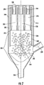
FIG. 1 illustrates a separator according to an embodiment, -
FIG. 2 illustrates liquid filming on walls of separator ofFIG. 1 , -
FIG. 3 illustrates a portion of the separator ofFIG. 1 , -
FIG. 4 illustrates a cylindrical body within the chamber of the separator ofFIG. 1 , and -
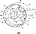
FIG. 5 illustrates the separator ofFIG. 1 in a bottom perspective view. - A detailed description of one or more embodiments of the disclosed apparatus and method are presented herein by way of exemplification and not limitation with reference to the Figures.
- Turning to
FIGS. 1-5 , disclosed is a liquid-vapor separator system 200 comprising achamber 210. Thechamber 210 comprises aninlet 220 for receiving two-phase fluid 225, afirst outlet 230 for draining theliquid portion 235, and asecond outlet 240 for egress ofgas 245. Thechamber 210 includes a plurality ofcircular channels 250 for transporting the two phase vapor therein, whereinfluid 235 films on thecircular channels 250 and drains through thefirst outlet 230. In one embodiment theinlet 220 is gravitationally above thefirst outlet 230 and gravitationally below thesecond outlet 240. - In one embodiment the plurality of
circular channels 250 are formed in abody 260, which may be cylindrical (hereinafter the "cylindrical body 260"). Thecylindrical body 260 has anouter wall 270 with an outer diameter and thechamber 260 has aninner wall 280 with an inner diameter. Theouter diameter 270 of the cylindrical body is smaller than theinner diameter 280 of the chamber to define anouter channel 290 in thechamber 210. With this configuration, capturedfluid 235 flows gravitationally along theouter channel 290 to thefirst outlet 230. In one embodiment thecylindrical body 260 has abottom surface 292, wherein thebottom surface 292 of thecylindrical body 260 is gravitationally above theinlet 220. In one embodiment thecylindrical body 260 has atop surface 294, wherein thetop surface 294 of thecylindrical body 260 is gravitationally below thesecond outlet 240. - In one embodiment the plurality of
circular channels 250 is a first plurality of circular channels. In such embodiment anendcap 296 may cover thetop surface 294 of thecylindrical body 260. Theend cap 296 may comprise a second plurality ofchannels 298 configured to be mating received in the respective first plurality ofcircular channels 250 so as to provide a gap between the plurality of channels. That is, this configuration defines a plurality ofcylindrical gap channels 299 at an axial top of the first plurality ofchannels 250 for capturing coalescing fluid and guiding coalescing fluid to theouter channel 290. - In one embodiment a
top portion 300 of thecylindrical body 260 comprises the plurality of circular channels and abottom portion 310 of thecylindrical body 260 comprises asingle channel 320. In one embodiment the cylindrical body has a constant outer diameter along its length so that thesingle channel 310 has a flow area that is substantially the same as a sum of the flow areas from the plurality ofcircular channels 260. In one embodiment thetop portion 300 and thebottom portion 310 have a same axial span. - In one embodiment the first outlet is frusto-conical. In one embodiment the second outlet is cylindrical having a diameter that defines a diameter of the chamber. In one embodiment the inlet is cylindrical having a first diameter that is smaller than a diameter of the chamber. As can be appreciated the above disclosed system may be used in a refrigerant system such as an aircraft heating ventilation and air conditioning (HVAC) system having an aircraft or land application. In such use, the fluid would be refrigerant.
- With the separator disclosed herein, vapor (along with entrained liquid droplets) flow through a series of circular channels. The channels are sized such that the flow develops an annular flow pattern. The flow develops in part to a liquid film coalesced on the channel walls. The liquid film is then stripped off by a second series of channels and returned to the liquid pool at the bottom of the separator. The disclosed process may provide an effective separation process with relatively low pressure drop. Benefits of the disclose embodiments include a reduced size and weight of flash tanks and heat exchangers, an improved flow distribution for evaporators (microchannel or brazed-plate), and an improved performance through flash gas bypass, especially for lower pressure refrigerants.
- The term "about" is intended to include the degree of error associated with measurement of the particular quantity based upon the equipment available at the time of filing the application.
- The terminology used herein is for the purpose of describing particular embodiments only and is not intended to be limiting of the present disclosure. As used herein, the singular forms "a", "an" and "the" are intended to include the plural forms as well, unless the context clearly indicates otherwise. It will be further understood that the terms "comprises" and/or "comprising," when used in this specification, specify the presence of stated features, integers, steps, operations, elements, and/or components, but do not preclude the presence or addition of one or more other features, integers, steps, operations, element components, and/or groups thereof.
- While the present disclosure has been described with reference to an exemplary embodiment or embodiments, it will be understood by those skilled in the art that various changes may be made and equivalents may be substituted for elements thereof without departing from the scope of the present disclosure. In addition, many modifications may be made to adapt a particular situation or material to the teachings of the present disclosure without departing from the essential scope thereof. Therefore, it is intended that the present disclosure not be limited to the particular embodiment disclosed as the best mode contemplated for carrying out this present disclosure, but that the present disclosure will include all embodiments falling within the scope of the claims.
Claims (15)
- A separation system comprising:
a chamber (210) comprising:an inlet (220) for receiving a two-phase fluid (225);a first outlet (230) for draining liquid contained in the two-phase fluid (225);a second outlet (240) for egress of gas (245) contained in the two-phase fluid (225);a body (260) disposed in the chamber (210) having a plurality of channels (250) through which, during use, the two-phase fluid (225) travels from the inlet (220) to the second outlet (240), and wherein the liquid within the two-phase fluid (225) coalesces on the walls of the plurality of channels (250) as the two-phase fluid (225) passes through the plurality of channels (250) and the liquid is returned to the first outlet (230). - The system of claim 1, wherein the inlet (220) is gravitationally above the first outlet (230) and gravitationally below the second outlet (240).
- The system of claims 1 or 2, wherein the body (260) is cylindrical and has an outer diameter that is smaller than a diameter of an inner wall (280) of the chamber (210), thereby defining an outer channel (290) in the chamber (210), wherein captured liquid flows gravitationally along the outer channel (290) to the first outlet (230).
- The system of claim 3, wherein the cylindrical body has a top surface (294), the top surface (294) being gravitationally below the second outlet (240) and preferably
wherein the plurality of circular channels is a first plurality of circular channels (250), wherein the system further includes:an endcap (296) covers the top surface (294) of the cylindrical body (260), the end cap (296) comprising a second plurality of circular channels (298) configured to be received within the respective first plurality of circular channels (250); and more preferablywherein a plurality of gap channels is defined between the second plurality circular channels (298) and the first plurality of circular channels (250) for capturing coalescing fluid and guiding coalescing fluid to the outer channel (290), and preferablywherein a top portion of the cylindrical body (260) comprises the plurality of circular channels (250), and a bottom portion of the cylindrical body (260) comprises a single channel (320), and more preferablywherein the top portion and the bottom portion of the cylindrical body (260) have a same length, and preferablywherein the cylindrical body (260) has a constant outer diameter so that the single channel (310) has a flow area that is substantially the same as a sum of the flow areas from the plurality of circular channels (260). - The system of any preceding claim, wherein the first outlet (230) is frusto-conical.
- The system of any preceding claim,, wherein the second outlet (240) is cylindrical having a diameter that defines a diameter of the chamber.
- The system of any preceding claim, wherein the inlet (220) is cylindrical having a first diameter that is smaller than a diameter of the chamber (210).
- A refrigerant system comprising the system of claim 1.
- The refrigerant of claim 8, wherein the two-phase fluid is evaporated refrigerant.
- A method of separating liquid and vapor comprising:receiving a two phase vapor at a chamber inlet,transporting the two phase vapor upwardly through a plurality of adjacently disposed circular channels in the chamber, whereby fluid coalesces on channel walls scooped through a gap, and drains through an outlet gravitationally below the inlet.
- The method of claim 10, wherein gas exits through an outlet located gravitationally above the inlet.
- The method of claims 11 or 12, wherein liquid drains through an outer channel defined between and outer wall of a cylindrical body and an inner wall of the chamber, wherein the cylindrical body comprises the plurality of adjacently disposed circular channels.
- The method of claim 12, wherein two phase fluid flows upwardly through a single channel in the chamber and then through the plurality of adjacently disposed circular channels, wherein a diameter of the single channel is greater than the diameters for the plurality of adjacently disposed circular channels.
- The method of claim 13, wherein the two phase fluid flows upwardly through the single channel by a same axial distance as through the plurality of adjacently disposed circular channels.
- The method of claim 14, wherein coalescing fluid is captured and guided to the outer channel by a plurality of cylindrical gap channels at an axial top of each of the plurality of cylindrical channels.
Applications Claiming Priority (1)
| Application Number | Priority Date | Filing Date | Title |
|---|---|---|---|
| US16/167,017 US10864993B2 (en) | 2018-10-22 | 2018-10-22 | Liquid vapor separator |
Publications (2)
| Publication Number | Publication Date |
|---|---|
| EP3643377A1 true EP3643377A1 (en) | 2020-04-29 |
| EP3643377B1 EP3643377B1 (en) | 2021-08-11 |
Family
ID=68296294
Family Applications (1)
| Application Number | Title | Priority Date | Filing Date |
|---|---|---|---|
| EP19204395.8A Active EP3643377B1 (en) | 2018-10-22 | 2019-10-21 | Liquid vapor separator |
Country Status (2)
| Country | Link |
|---|---|
| US (1) | US10864993B2 (en) |
| EP (1) | EP3643377B1 (en) |
Families Citing this family (1)
| Publication number | Priority date | Publication date | Assignee | Title |
|---|---|---|---|---|
| CN113813701A (en) * | 2021-10-19 | 2021-12-21 | 深圳市宏康环境科技有限公司 | Remove comdenstion water device and negative oxygen ion generating equipment |
Citations (4)
| Publication number | Priority date | Publication date | Assignee | Title |
|---|---|---|---|---|
| GB1192146A (en) * | 1967-11-15 | 1970-05-20 | Siemens Ag | Device for the Gravity Separation of Gaseous-Liquid Mixtures |
| US6238464B1 (en) * | 1997-10-13 | 2001-05-29 | Dullien Francis A.L. | Method and apparatus for separating droplets for particles from a gas stream |
| US20110011105A1 (en) * | 2007-07-12 | 2011-01-20 | Johnson Controls Technology Company | Oil separator |
| US20110056379A1 (en) * | 2009-09-09 | 2011-03-10 | Ingersoll-Rand Company | Multi-stage oil separation system including a cyclonic separation stage |
Family Cites Families (9)
| Publication number | Priority date | Publication date | Assignee | Title |
|---|---|---|---|---|
| US3791444A (en) * | 1973-01-29 | 1974-02-12 | W Hickey | Liquid gas separator |
| US5314529A (en) | 1993-09-13 | 1994-05-24 | Tilton Donald E | Entrained droplet separator |
| NL1020113C2 (en) * | 2002-03-05 | 2003-09-10 | Statoil Asa | Device and method for treating a gas / liquid mixture. |
| WO2005023396A1 (en) * | 2003-09-09 | 2005-03-17 | Shell Internationale Research Maatschappij B.V. | Gas/liquid separator |
| JP4715561B2 (en) * | 2006-03-06 | 2011-07-06 | ダイキン工業株式会社 | Refrigeration equipment |
| NO326577B1 (en) * | 2006-03-23 | 2009-01-12 | Natco Norway As | Axially flowing cyclone for separation of gas, liquid and particulate matter mixtures |
| NO330124B1 (en) | 2009-06-11 | 2011-02-21 | Ntnu Tech Transfer As | A separator for a gas / liquid stream |
| CN104039410A (en) * | 2011-12-16 | 2014-09-10 | 国际壳牌研究有限公司 | Contact and separation column and tray |
| US10612824B2 (en) | 2016-05-06 | 2020-04-07 | Hamilton Sundstrand Corporation | Gas-liquid phase separator |
-
2018
- 2018-10-22 US US16/167,017 patent/US10864993B2/en active Active
-
2019
- 2019-10-21 EP EP19204395.8A patent/EP3643377B1/en active Active
Patent Citations (4)
| Publication number | Priority date | Publication date | Assignee | Title |
|---|---|---|---|---|
| GB1192146A (en) * | 1967-11-15 | 1970-05-20 | Siemens Ag | Device for the Gravity Separation of Gaseous-Liquid Mixtures |
| US6238464B1 (en) * | 1997-10-13 | 2001-05-29 | Dullien Francis A.L. | Method and apparatus for separating droplets for particles from a gas stream |
| US20110011105A1 (en) * | 2007-07-12 | 2011-01-20 | Johnson Controls Technology Company | Oil separator |
| US20110056379A1 (en) * | 2009-09-09 | 2011-03-10 | Ingersoll-Rand Company | Multi-stage oil separation system including a cyclonic separation stage |
Also Published As
| Publication number | Publication date |
|---|---|
| US20200122842A1 (en) | 2020-04-23 |
| US10864993B2 (en) | 2020-12-15 |
| EP3643377B1 (en) | 2021-08-11 |
Similar Documents
| Publication | Publication Date | Title |
|---|---|---|
| CN108779968B (en) | heat exchanger | |
| CN113227698B (en) | heat exchanger | |
| US11137183B2 (en) | Phobic/philic structures in refrigeration systems and liquid vapor separation in refrigeration systems | |
| EP3586938B1 (en) | Helical water collector | |
| EP3087335B1 (en) | Distributor for falling film evaporator | |
| EP3690335B1 (en) | Improved high pressure water extraction device with shave off edge that feeds a low pressure chamber to improve water collection and drainage | |
| CN113227697A (en) | Heat exchanger | |
| EP3643377B1 (en) | Liquid vapor separator | |
| EP3042127B1 (en) | Integrated separator-distributor for falling film evaporator | |
| US7470300B2 (en) | Duct wall water extractor | |
| IL264147A (en) | In-line water separator | |
| EP3661623B1 (en) | Desorber for air conditioning system having integrated microemulsion-based air dehumidification | |
| US20200271402A1 (en) | Helical insert for shell and tube heat exchanger | |
| US6589322B2 (en) | Oil seal liquid separator | |
| EP3775722B1 (en) | Integrated separator and distributor | |
| CN113195997A (en) | heat exchanger | |
| EP4154965B1 (en) | Passive phase separator with liquid removal chamber | |
| CN112156489B (en) | MVR evaporator and MVR evaporation system | |
| CN119778917A (en) | Condenser vessel, system and method for separating oil from an oil-refrigerant mixture | |
| WO2005071329A1 (en) | Parallel flow evaporator | |
| SU1112169A1 (en) | Separating apparatus | |
| HU207893B (en) | Apparatus for condensing and separating vapours from flowing gases | |
| HU194062B (en) | Supermultiflash type evaporation device |
Legal Events
| Date | Code | Title | Description |
|---|---|---|---|
| PUAI | Public reference made under article 153(3) epc to a published international application that has entered the european phase |
Free format text: ORIGINAL CODE: 0009012 |
|
| STAA | Information on the status of an ep patent application or granted ep patent |
Free format text: STATUS: THE APPLICATION HAS BEEN PUBLISHED |
|
| AK | Designated contracting states |
Kind code of ref document: A1 Designated state(s): AL AT BE BG CH CY CZ DE DK EE ES FI FR GB GR HR HU IE IS IT LI LT LU LV MC MK MT NL NO PL PT RO RS SE SI SK SM TR |
|
| AX | Request for extension of the european patent |
Extension state: BA ME |
|
| STAA | Information on the status of an ep patent application or granted ep patent |
Free format text: STATUS: REQUEST FOR EXAMINATION WAS MADE |
|
| 17P | Request for examination filed |
Effective date: 20201027 |
|
| RBV | Designated contracting states (corrected) |
Designated state(s): AL AT BE BG CH CY CZ DE DK EE ES FI FR GB GR HR HU IE IS IT LI LT LU LV MC MK MT NL NO PL PT RO RS SE SI SK SM TR |
|
| GRAP | Despatch of communication of intention to grant a patent |
Free format text: ORIGINAL CODE: EPIDOSNIGR1 |
|
| STAA | Information on the status of an ep patent application or granted ep patent |
Free format text: STATUS: GRANT OF PATENT IS INTENDED |
|
| INTG | Intention to grant announced |
Effective date: 20210315 |
|
| GRAS | Grant fee paid |
Free format text: ORIGINAL CODE: EPIDOSNIGR3 |
|
| GRAA | (expected) grant |
Free format text: ORIGINAL CODE: 0009210 |
|
| STAA | Information on the status of an ep patent application or granted ep patent |
Free format text: STATUS: THE PATENT HAS BEEN GRANTED |
|
| AK | Designated contracting states |
Kind code of ref document: B1 Designated state(s): AL AT BE BG CH CY CZ DE DK EE ES FI FR GB GR HR HU IE IS IT LI LT LU LV MC MK MT NL NO PL PT RO RS SE SI SK SM TR |
|
| REG | Reference to a national code |
Ref country code: CH Ref legal event code: EP |
|
| REG | Reference to a national code |
Ref country code: DE Ref legal event code: R096 Ref document number: 602019006776 Country of ref document: DE |
|
| REG | Reference to a national code |
Ref country code: IE Ref legal event code: FG4D Ref country code: AT Ref legal event code: REF Ref document number: 1418785 Country of ref document: AT Kind code of ref document: T Effective date: 20210915 |
|
| REG | Reference to a national code |
Ref country code: LT Ref legal event code: MG9D |
|
| REG | Reference to a national code |
Ref country code: NL Ref legal event code: MP Effective date: 20210811 |
|
| REG | Reference to a national code |
Ref country code: AT Ref legal event code: MK05 Ref document number: 1418785 Country of ref document: AT Kind code of ref document: T Effective date: 20210811 |
|
| PG25 | Lapsed in a contracting state [announced via postgrant information from national office to epo] |
Ref country code: SE Free format text: LAPSE BECAUSE OF FAILURE TO SUBMIT A TRANSLATION OF THE DESCRIPTION OR TO PAY THE FEE WITHIN THE PRESCRIBED TIME-LIMIT Effective date: 20210811 Ref country code: RS Free format text: LAPSE BECAUSE OF FAILURE TO SUBMIT A TRANSLATION OF THE DESCRIPTION OR TO PAY THE FEE WITHIN THE PRESCRIBED TIME-LIMIT Effective date: 20210811 Ref country code: ES Free format text: LAPSE BECAUSE OF FAILURE TO SUBMIT A TRANSLATION OF THE DESCRIPTION OR TO PAY THE FEE WITHIN THE PRESCRIBED TIME-LIMIT Effective date: 20210811 Ref country code: LT Free format text: LAPSE BECAUSE OF FAILURE TO SUBMIT A TRANSLATION OF THE DESCRIPTION OR TO PAY THE FEE WITHIN THE PRESCRIBED TIME-LIMIT Effective date: 20210811 Ref country code: BG Free format text: LAPSE BECAUSE OF FAILURE TO SUBMIT A TRANSLATION OF THE DESCRIPTION OR TO PAY THE FEE WITHIN THE PRESCRIBED TIME-LIMIT Effective date: 20211111 Ref country code: AT Free format text: LAPSE BECAUSE OF FAILURE TO SUBMIT A TRANSLATION OF THE DESCRIPTION OR TO PAY THE FEE WITHIN THE PRESCRIBED TIME-LIMIT Effective date: 20210811 Ref country code: FI Free format text: LAPSE BECAUSE OF FAILURE TO SUBMIT A TRANSLATION OF THE DESCRIPTION OR TO PAY THE FEE WITHIN THE PRESCRIBED TIME-LIMIT Effective date: 20210811 Ref country code: HR Free format text: LAPSE BECAUSE OF FAILURE TO SUBMIT A TRANSLATION OF THE DESCRIPTION OR TO PAY THE FEE WITHIN THE PRESCRIBED TIME-LIMIT Effective date: 20210811 Ref country code: NO Free format text: LAPSE BECAUSE OF FAILURE TO SUBMIT A TRANSLATION OF THE DESCRIPTION OR TO PAY THE FEE WITHIN THE PRESCRIBED TIME-LIMIT Effective date: 20211111 Ref country code: PT Free format text: LAPSE BECAUSE OF FAILURE TO SUBMIT A TRANSLATION OF THE DESCRIPTION OR TO PAY THE FEE WITHIN THE PRESCRIBED TIME-LIMIT Effective date: 20211213 |
|
| PG25 | Lapsed in a contracting state [announced via postgrant information from national office to epo] |
Ref country code: PL Free format text: LAPSE BECAUSE OF FAILURE TO SUBMIT A TRANSLATION OF THE DESCRIPTION OR TO PAY THE FEE WITHIN THE PRESCRIBED TIME-LIMIT Effective date: 20210811 Ref country code: LV Free format text: LAPSE BECAUSE OF FAILURE TO SUBMIT A TRANSLATION OF THE DESCRIPTION OR TO PAY THE FEE WITHIN THE PRESCRIBED TIME-LIMIT Effective date: 20210811 Ref country code: GR Free format text: LAPSE BECAUSE OF FAILURE TO SUBMIT A TRANSLATION OF THE DESCRIPTION OR TO PAY THE FEE WITHIN THE PRESCRIBED TIME-LIMIT Effective date: 20211112 |
|
| PG25 | Lapsed in a contracting state [announced via postgrant information from national office to epo] |
Ref country code: NL Free format text: LAPSE BECAUSE OF FAILURE TO SUBMIT A TRANSLATION OF THE DESCRIPTION OR TO PAY THE FEE WITHIN THE PRESCRIBED TIME-LIMIT Effective date: 20210811 |
|
| PG25 | Lapsed in a contracting state [announced via postgrant information from national office to epo] |
Ref country code: DK Free format text: LAPSE BECAUSE OF FAILURE TO SUBMIT A TRANSLATION OF THE DESCRIPTION OR TO PAY THE FEE WITHIN THE PRESCRIBED TIME-LIMIT Effective date: 20210811 |
|
| REG | Reference to a national code |
Ref country code: DE Ref legal event code: R097 Ref document number: 602019006776 Country of ref document: DE |
|
| PG25 | Lapsed in a contracting state [announced via postgrant information from national office to epo] |
Ref country code: SM Free format text: LAPSE BECAUSE OF FAILURE TO SUBMIT A TRANSLATION OF THE DESCRIPTION OR TO PAY THE FEE WITHIN THE PRESCRIBED TIME-LIMIT Effective date: 20210811 Ref country code: SK Free format text: LAPSE BECAUSE OF FAILURE TO SUBMIT A TRANSLATION OF THE DESCRIPTION OR TO PAY THE FEE WITHIN THE PRESCRIBED TIME-LIMIT Effective date: 20210811 Ref country code: RO Free format text: LAPSE BECAUSE OF FAILURE TO SUBMIT A TRANSLATION OF THE DESCRIPTION OR TO PAY THE FEE WITHIN THE PRESCRIBED TIME-LIMIT Effective date: 20210811 Ref country code: EE Free format text: LAPSE BECAUSE OF FAILURE TO SUBMIT A TRANSLATION OF THE DESCRIPTION OR TO PAY THE FEE WITHIN THE PRESCRIBED TIME-LIMIT Effective date: 20210811 Ref country code: CZ Free format text: LAPSE BECAUSE OF FAILURE TO SUBMIT A TRANSLATION OF THE DESCRIPTION OR TO PAY THE FEE WITHIN THE PRESCRIBED TIME-LIMIT Effective date: 20210811 Ref country code: AL Free format text: LAPSE BECAUSE OF FAILURE TO SUBMIT A TRANSLATION OF THE DESCRIPTION OR TO PAY THE FEE WITHIN THE PRESCRIBED TIME-LIMIT Effective date: 20210811 |
|
| PLBE | No opposition filed within time limit |
Free format text: ORIGINAL CODE: 0009261 |
|
| STAA | Information on the status of an ep patent application or granted ep patent |
Free format text: STATUS: NO OPPOSITION FILED WITHIN TIME LIMIT |
|
| REG | Reference to a national code |
Ref country code: BE Ref legal event code: MM Effective date: 20211031 |
|
| PG25 | Lapsed in a contracting state [announced via postgrant information from national office to epo] |
Ref country code: MC Free format text: LAPSE BECAUSE OF FAILURE TO SUBMIT A TRANSLATION OF THE DESCRIPTION OR TO PAY THE FEE WITHIN THE PRESCRIBED TIME-LIMIT Effective date: 20210811 |
|
| 26N | No opposition filed |
Effective date: 20220512 |
|
| PG25 | Lapsed in a contracting state [announced via postgrant information from national office to epo] |
Ref country code: IT Free format text: LAPSE BECAUSE OF FAILURE TO SUBMIT A TRANSLATION OF THE DESCRIPTION OR TO PAY THE FEE WITHIN THE PRESCRIBED TIME-LIMIT Effective date: 20210811 Ref country code: BE Free format text: LAPSE BECAUSE OF NON-PAYMENT OF DUE FEES Effective date: 20211031 Ref country code: LU Free format text: LAPSE BECAUSE OF NON-PAYMENT OF DUE FEES Effective date: 20211021 |
|
| PG25 | Lapsed in a contracting state [announced via postgrant information from national office to epo] |
Ref country code: SI Free format text: LAPSE BECAUSE OF FAILURE TO SUBMIT A TRANSLATION OF THE DESCRIPTION OR TO PAY THE FEE WITHIN THE PRESCRIBED TIME-LIMIT Effective date: 20210811 |
|
| PG25 | Lapsed in a contracting state [announced via postgrant information from national office to epo] |
Ref country code: IE Free format text: LAPSE BECAUSE OF NON-PAYMENT OF DUE FEES Effective date: 20211021 |
|
| REG | Reference to a national code |
Ref country code: CH Ref legal event code: PL |
|
| PG25 | Lapsed in a contracting state [announced via postgrant information from national office to epo] |
Ref country code: CY Free format text: LAPSE BECAUSE OF FAILURE TO SUBMIT A TRANSLATION OF THE DESCRIPTION OR TO PAY THE FEE WITHIN THE PRESCRIBED TIME-LIMIT Effective date: 20210811 |
|
| P01 | Opt-out of the competence of the unified patent court (upc) registered |
Effective date: 20230603 |
|
| PG25 | Lapsed in a contracting state [announced via postgrant information from national office to epo] |
Ref country code: LI Free format text: LAPSE BECAUSE OF NON-PAYMENT OF DUE FEES Effective date: 20221031 Ref country code: HU Free format text: LAPSE BECAUSE OF FAILURE TO SUBMIT A TRANSLATION OF THE DESCRIPTION OR TO PAY THE FEE WITHIN THE PRESCRIBED TIME-LIMIT; INVALID AB INITIO Effective date: 20191021 Ref country code: CH Free format text: LAPSE BECAUSE OF NON-PAYMENT OF DUE FEES Effective date: 20221031 |
|
| PG25 | Lapsed in a contracting state [announced via postgrant information from national office to epo] |
Ref country code: MK Free format text: LAPSE BECAUSE OF FAILURE TO SUBMIT A TRANSLATION OF THE DESCRIPTION OR TO PAY THE FEE WITHIN THE PRESCRIBED TIME-LIMIT Effective date: 20210811 |
|
| PG25 | Lapsed in a contracting state [announced via postgrant information from national office to epo] |
Ref country code: MT Free format text: LAPSE BECAUSE OF FAILURE TO SUBMIT A TRANSLATION OF THE DESCRIPTION OR TO PAY THE FEE WITHIN THE PRESCRIBED TIME-LIMIT Effective date: 20210811 |
|
| PGFP | Annual fee paid to national office [announced via postgrant information from national office to epo] |
Ref country code: GB Payment date: 20250923 Year of fee payment: 7 |
|
| PGFP | Annual fee paid to national office [announced via postgrant information from national office to epo] |
Ref country code: FR Payment date: 20250924 Year of fee payment: 7 |
|
| PG25 | Lapsed in a contracting state [announced via postgrant information from national office to epo] |
Ref country code: TR Free format text: LAPSE BECAUSE OF FAILURE TO SUBMIT A TRANSLATION OF THE DESCRIPTION OR TO PAY THE FEE WITHIN THE PRESCRIBED TIME-LIMIT Effective date: 20210811 |
|
| PGFP | Annual fee paid to national office [announced via postgrant information from national office to epo] |
Ref country code: DE Payment date: 20250923 Year of fee payment: 7 |