EP3642496B1 - Piece mecanique modulaire - Google Patents
Piece mecanique modulaire Download PDFInfo
- Publication number
- EP3642496B1 EP3642496B1 EP18729172.9A EP18729172A EP3642496B1 EP 3642496 B1 EP3642496 B1 EP 3642496B1 EP 18729172 A EP18729172 A EP 18729172A EP 3642496 B1 EP3642496 B1 EP 3642496B1
- Authority
- EP
- European Patent Office
- Prior art keywords
- coupling
- inner ring
- copper
- part according
- mechanical timepiece
- Prior art date
- Legal status (The legal status is an assumption and is not a legal conclusion. Google has not performed a legal analysis and makes no representation as to the accuracy of the status listed.)
- Active
Links
- 230000008878 coupling Effects 0.000 claims description 50
- 238000010168 coupling process Methods 0.000 claims description 50
- 238000005859 coupling reaction Methods 0.000 claims description 50
- 238000004804 winding Methods 0.000 claims description 8
- 229910000831 Steel Inorganic materials 0.000 claims description 6
- 239000000696 magnetic material Substances 0.000 claims description 6
- 239000010959 steel Substances 0.000 claims description 6
- XAGFODPZIPBFFR-UHFFFAOYSA-N aluminium Chemical compound [Al] XAGFODPZIPBFFR-UHFFFAOYSA-N 0.000 claims description 5
- 229910001069 Ti alloy Inorganic materials 0.000 claims description 4
- 229910052782 aluminium Inorganic materials 0.000 claims description 4
- KUNSUQLRTQLHQQ-UHFFFAOYSA-N copper tin Chemical compound [Cu].[Sn] KUNSUQLRTQLHQQ-UHFFFAOYSA-N 0.000 claims description 4
- 239000000463 material Substances 0.000 claims description 4
- 229910001369 Brass Inorganic materials 0.000 claims description 3
- 229910000906 Bronze Inorganic materials 0.000 claims description 3
- 229910000531 Co alloy Inorganic materials 0.000 claims description 3
- 229910000570 Cupronickel Inorganic materials 0.000 claims description 3
- 229910000990 Ni alloy Inorganic materials 0.000 claims description 3
- JUWOETZNAMLKMG-UHFFFAOYSA-N [P].[Ni].[Cu] Chemical compound [P].[Ni].[Cu] JUWOETZNAMLKMG-UHFFFAOYSA-N 0.000 claims description 3
- ZUPBPXNOBDEWQT-UHFFFAOYSA-N [Si].[Ni].[Cu] Chemical compound [Si].[Ni].[Cu] ZUPBPXNOBDEWQT-UHFFFAOYSA-N 0.000 claims description 3
- VRUVRQYVUDCDMT-UHFFFAOYSA-N [Sn].[Ni].[Cu] Chemical compound [Sn].[Ni].[Cu] VRUVRQYVUDCDMT-UHFFFAOYSA-N 0.000 claims description 3
- 239000010951 brass Substances 0.000 claims description 3
- 239000010974 bronze Substances 0.000 claims description 3
- 239000000919 ceramic Substances 0.000 claims description 3
- YOCUPQPZWBBYIX-UHFFFAOYSA-N copper nickel Chemical compound [Ni].[Cu] YOCUPQPZWBBYIX-UHFFFAOYSA-N 0.000 claims description 3
- IUYOGGFTLHZHEG-UHFFFAOYSA-N copper titanium Chemical compound [Ti].[Cu] IUYOGGFTLHZHEG-UHFFFAOYSA-N 0.000 claims description 3
- TVZPLCNGKSPOJA-UHFFFAOYSA-N copper zinc Chemical compound [Cu].[Zn] TVZPLCNGKSPOJA-UHFFFAOYSA-N 0.000 claims description 3
- 238000002788 crimping Methods 0.000 claims description 3
- MOFOBJHOKRNACT-UHFFFAOYSA-N nickel silver Chemical compound [Ni].[Ag] MOFOBJHOKRNACT-UHFFFAOYSA-N 0.000 claims description 3
- 239000010956 nickel silver Substances 0.000 claims description 3
- 229910001220 stainless steel Inorganic materials 0.000 claims description 3
- 239000010935 stainless steel Substances 0.000 claims description 3
- 238000003466 welding Methods 0.000 claims description 3
- JRBRVDCKNXZZGH-UHFFFAOYSA-N alumane;copper Chemical compound [AlH3].[Cu] JRBRVDCKNXZZGH-UHFFFAOYSA-N 0.000 claims description 2
- 239000011248 coating agent Substances 0.000 claims description 2
- 238000000576 coating method Methods 0.000 claims description 2
- RVTZCBVAJQQJTK-UHFFFAOYSA-N oxygen(2-);zirconium(4+) Chemical compound [O-2].[O-2].[Zr+4] RVTZCBVAJQQJTK-UHFFFAOYSA-N 0.000 claims description 2
- 230000035945 sensitivity Effects 0.000 claims description 2
- 229910001928 zirconium oxide Inorganic materials 0.000 claims description 2
- 229910000838 Al alloy Inorganic materials 0.000 claims 1
- 239000004809 Teflon Substances 0.000 claims 1
- 229920006362 Teflon® Polymers 0.000 claims 1
- 239000004411 aluminium Substances 0.000 claims 1
- 229910052790 beryllium Inorganic materials 0.000 claims 1
- 229910045601 alloy Inorganic materials 0.000 description 19
- 239000000956 alloy Substances 0.000 description 19
- PXHVJJICTQNCMI-UHFFFAOYSA-N nickel Substances [Ni] PXHVJJICTQNCMI-UHFFFAOYSA-N 0.000 description 6
- 229910052759 nickel Inorganic materials 0.000 description 5
- 239000000203 mixture Substances 0.000 description 4
- 235000008612 Gnetum gnemon Nutrition 0.000 description 3
- 240000000018 Gnetum gnemon Species 0.000 description 3
- 238000007747 plating Methods 0.000 description 3
- 229910000952 Be alloy Inorganic materials 0.000 description 2
- 229910017518 Cu Zn Inorganic materials 0.000 description 2
- 229910017752 Cu-Zn Inorganic materials 0.000 description 2
- 229910017943 Cu—Zn Inorganic materials 0.000 description 2
- 241001275902 Parabramis pekinensis Species 0.000 description 2
- 239000000654 additive Substances 0.000 description 2
- 238000004026 adhesive bonding Methods 0.000 description 2
- 229910052804 chromium Inorganic materials 0.000 description 2
- 238000004519 manufacturing process Methods 0.000 description 2
- 229910000881 Cu alloy Inorganic materials 0.000 description 1
- 229910017755 Cu-Sn Inorganic materials 0.000 description 1
- 229910017927 Cu—Sn Inorganic materials 0.000 description 1
- 229910018648 Mn—N Inorganic materials 0.000 description 1
- 229910018605 Ni—Zn Inorganic materials 0.000 description 1
- 229910001096 P alloy Inorganic materials 0.000 description 1
- 229910001128 Sn alloy Inorganic materials 0.000 description 1
- 241001080024 Telles Species 0.000 description 1
- RTAQQCXQSZGOHL-UHFFFAOYSA-N Titanium Chemical compound [Ti] RTAQQCXQSZGOHL-UHFFFAOYSA-N 0.000 description 1
- 229910000963 austenitic stainless steel Inorganic materials 0.000 description 1
- 239000010941 cobalt Substances 0.000 description 1
- 229910017052 cobalt Inorganic materials 0.000 description 1
- GUTLYIVDDKVIGB-UHFFFAOYSA-N cobalt atom Chemical compound [Co] GUTLYIVDDKVIGB-UHFFFAOYSA-N 0.000 description 1
- 239000000470 constituent Substances 0.000 description 1
- 239000010949 copper Substances 0.000 description 1
- 230000001419 dependent effect Effects 0.000 description 1
- 239000003814 drug Substances 0.000 description 1
- 238000009434 installation Methods 0.000 description 1
- 229910052745 lead Inorganic materials 0.000 description 1
- 229910001004 magnetic alloy Inorganic materials 0.000 description 1
- 238000000034 method Methods 0.000 description 1
- 229910052750 molybdenum Inorganic materials 0.000 description 1
- 229910021484 silicon-nickel alloy Inorganic materials 0.000 description 1
- 229910052718 tin Inorganic materials 0.000 description 1
- 239000010936 titanium Substances 0.000 description 1
- 229910052719 titanium Inorganic materials 0.000 description 1
- 230000001131 transforming effect Effects 0.000 description 1
- 238000011282 treatment Methods 0.000 description 1
- 230000003245 working effect Effects 0.000 description 1
Images

Classifications
-
- F—MECHANICAL ENGINEERING; LIGHTING; HEATING; WEAPONS; BLASTING
- F16—ENGINEERING ELEMENTS AND UNITS; GENERAL MEASURES FOR PRODUCING AND MAINTAINING EFFECTIVE FUNCTIONING OF MACHINES OR INSTALLATIONS; THERMAL INSULATION IN GENERAL
- F16C—SHAFTS; FLEXIBLE SHAFTS; ELEMENTS OR CRANKSHAFT MECHANISMS; ROTARY BODIES OTHER THAN GEARING ELEMENTS; BEARINGS
- F16C19/00—Bearings with rolling contact, for exclusively rotary movement
- F16C19/02—Bearings with rolling contact, for exclusively rotary movement with bearing balls essentially of the same size in one or more circular rows
- F16C19/14—Bearings with rolling contact, for exclusively rotary movement with bearing balls essentially of the same size in one or more circular rows for both radial and axial load
- F16C19/16—Bearings with rolling contact, for exclusively rotary movement with bearing balls essentially of the same size in one or more circular rows for both radial and axial load with a single row of balls
- F16C19/163—Bearings with rolling contact, for exclusively rotary movement with bearing balls essentially of the same size in one or more circular rows for both radial and axial load with a single row of balls with angular contact
- F16C19/166—Four-point-contact ball bearings
-
- F—MECHANICAL ENGINEERING; LIGHTING; HEATING; WEAPONS; BLASTING
- F16—ENGINEERING ELEMENTS AND UNITS; GENERAL MEASURES FOR PRODUCING AND MAINTAINING EFFECTIVE FUNCTIONING OF MACHINES OR INSTALLATIONS; THERMAL INSULATION IN GENERAL
- F16C—SHAFTS; FLEXIBLE SHAFTS; ELEMENTS OR CRANKSHAFT MECHANISMS; ROTARY BODIES OTHER THAN GEARING ELEMENTS; BEARINGS
- F16C33/00—Parts of bearings; Special methods for making bearings or parts thereof
- F16C33/30—Parts of ball or roller bearings
- F16C33/58—Raceways; Race rings
- F16C33/581—Raceways; Race rings integral with other parts, e.g. with housings or machine elements such as shafts or gear wheels
-
- G04B13/026—
-
- G—PHYSICS
- G04—HOROLOGY
- G04B—MECHANICALLY-DRIVEN CLOCKS OR WATCHES; MECHANICAL PARTS OF CLOCKS OR WATCHES IN GENERAL; TIME PIECES USING THE POSITION OF THE SUN, MOON OR STARS
- G04B31/00—Bearings; Point suspensions or counter-point suspensions; Pivot bearings; Single parts therefor
- G04B31/004—Bearings; Point suspensions or counter-point suspensions; Pivot bearings; Single parts therefor characterised by the material used
- G04B31/012—Metallic bearings
- G04B31/0123—Metallic bearings with metallic ball bearings and metallic roller bearings
-
- G—PHYSICS
- G04—HOROLOGY
- G04B—MECHANICALLY-DRIVEN CLOCKS OR WATCHES; MECHANICAL PARTS OF CLOCKS OR WATCHES IN GENERAL; TIME PIECES USING THE POSITION OF THE SUN, MOON OR STARS
- G04B43/00—Protecting clockworks by shields or other means against external influences, e.g. magnetic fields
- G04B43/007—Antimagnetic alloys
-
- G—PHYSICS
- G04—HOROLOGY
- G04B—MECHANICALLY-DRIVEN CLOCKS OR WATCHES; MECHANICAL PARTS OF CLOCKS OR WATCHES IN GENERAL; TIME PIECES USING THE POSITION OF THE SUN, MOON OR STARS
- G04B5/00—Automatic winding up
- G04B5/02—Automatic winding up by self-winding caused by the movement of the watch
- G04B5/18—Supports, suspensions or guide arrangements, for oscillating weights
- G04B5/19—Suspension of the oscillating weight at its centre of rotation
-
- F—MECHANICAL ENGINEERING; LIGHTING; HEATING; WEAPONS; BLASTING
- F16—ENGINEERING ELEMENTS AND UNITS; GENERAL MEASURES FOR PRODUCING AND MAINTAINING EFFECTIVE FUNCTIONING OF MACHINES OR INSTALLATIONS; THERMAL INSULATION IN GENERAL
- F16C—SHAFTS; FLEXIBLE SHAFTS; ELEMENTS OR CRANKSHAFT MECHANISMS; ROTARY BODIES OTHER THAN GEARING ELEMENTS; BEARINGS
- F16C2204/00—Metallic materials; Alloys
- F16C2204/20—Alloys based on aluminium
-
- F—MECHANICAL ENGINEERING; LIGHTING; HEATING; WEAPONS; BLASTING
- F16—ENGINEERING ELEMENTS AND UNITS; GENERAL MEASURES FOR PRODUCING AND MAINTAINING EFFECTIVE FUNCTIONING OF MACHINES OR INSTALLATIONS; THERMAL INSULATION IN GENERAL
- F16C—SHAFTS; FLEXIBLE SHAFTS; ELEMENTS OR CRANKSHAFT MECHANISMS; ROTARY BODIES OTHER THAN GEARING ELEMENTS; BEARINGS
- F16C2204/00—Metallic materials; Alloys
- F16C2204/60—Ferrous alloys, e.g. steel alloys
-
- F—MECHANICAL ENGINEERING; LIGHTING; HEATING; WEAPONS; BLASTING
- F16—ENGINEERING ELEMENTS AND UNITS; GENERAL MEASURES FOR PRODUCING AND MAINTAINING EFFECTIVE FUNCTIONING OF MACHINES OR INSTALLATIONS; THERMAL INSULATION IN GENERAL
- F16C—SHAFTS; FLEXIBLE SHAFTS; ELEMENTS OR CRANKSHAFT MECHANISMS; ROTARY BODIES OTHER THAN GEARING ELEMENTS; BEARINGS
- F16C2206/00—Materials with ceramics, cermets, hard carbon or similar non-metallic hard materials as main constituents
- F16C2206/40—Ceramics, e.g. carbides, nitrides, oxides, borides of a metal
- F16C2206/42—Ceramics, e.g. carbides, nitrides, oxides, borides of a metal based on ceramic oxides
- F16C2206/48—Ceramics, e.g. carbides, nitrides, oxides, borides of a metal based on ceramic oxides based on zirconia (ZrO2)
-
- F—MECHANICAL ENGINEERING; LIGHTING; HEATING; WEAPONS; BLASTING
- F16—ENGINEERING ELEMENTS AND UNITS; GENERAL MEASURES FOR PRODUCING AND MAINTAINING EFFECTIVE FUNCTIONING OF MACHINES OR INSTALLATIONS; THERMAL INSULATION IN GENERAL
- F16C—SHAFTS; FLEXIBLE SHAFTS; ELEMENTS OR CRANKSHAFT MECHANISMS; ROTARY BODIES OTHER THAN GEARING ELEMENTS; BEARINGS
- F16C2316/00—Apparatus in health or amusement
- F16C2316/10—Apparatus in health or amusement in medical appliances, e.g. in diagnosis, dentistry, instruments, prostheses, medical imaging appliances
-
- F—MECHANICAL ENGINEERING; LIGHTING; HEATING; WEAPONS; BLASTING
- F16—ENGINEERING ELEMENTS AND UNITS; GENERAL MEASURES FOR PRODUCING AND MAINTAINING EFFECTIVE FUNCTIONING OF MACHINES OR INSTALLATIONS; THERMAL INSULATION IN GENERAL
- F16C—SHAFTS; FLEXIBLE SHAFTS; ELEMENTS OR CRANKSHAFT MECHANISMS; ROTARY BODIES OTHER THAN GEARING ELEMENTS; BEARINGS
- F16C2361/00—Apparatus or articles in engineering in general
- F16C2361/61—Toothed gear systems, e.g. support of pinion shafts
-
- F—MECHANICAL ENGINEERING; LIGHTING; HEATING; WEAPONS; BLASTING
- F16—ENGINEERING ELEMENTS AND UNITS; GENERAL MEASURES FOR PRODUCING AND MAINTAINING EFFECTIVE FUNCTIONING OF MACHINES OR INSTALLATIONS; THERMAL INSULATION IN GENERAL
- F16C—SHAFTS; FLEXIBLE SHAFTS; ELEMENTS OR CRANKSHAFT MECHANISMS; ROTARY BODIES OTHER THAN GEARING ELEMENTS; BEARINGS
- F16C2370/00—Apparatus relating to physics, e.g. instruments
Definitions
- the invention relates to a mechanical part comprising a ball bearing.
- the invention finds application more particularly in the field of watchmaking but can also be considered for applications in the field of medicine or micromechanics.
- a ball bearing comprises a concentric outer ring and an inner ring together defining a raceway for a plurality of balls so that each ball is in contact with said rings at a plurality of contact points, the balls being separated from each other by a cage.
- a bearing is for example described in the publication EP1520111 .
- the external wall of the external ring is generally toothed to mesh with an external gear and the internal ring can be pierced with a recess to allow its attachment .
- a bearing can be used, among other things, to suspend an oscillating mass in a mechanical watch movement.
- each watch movement has its own means of attachment and its own workings, so that a bearing is in fact intended exclusively for a host watch movement for which it was designed. This therefore involves manufacturing, storing and managing a large number of bearing references each dedicated to a host movement, which complicates and increases the cost of the movement manufacturing process.
- the bearings have the disadvantage of being generally made of magnetic materials and of being likely to disrupt the operation of movements equipped with these bearings, after having been subjected to a magnetic field.
- the inner outer rings together define a raceway for the balls.
- the internal ring comprises a central recess and the mechanical part also comprises a coupling core (27) fixed inside the central recess of the internal ring, said coupling core being adapted to cooperate with a means of corresponding external coupling (3) to allow rotation of the internal ring relative to the external ring.
- the invention aims to improve the known technique, by proposing a solution aimed at overcoming all or part of the disadvantages or limitations of the bearings described above.
- the invention proposes a mechanical watch part as defined in independent claim 1 appended.
- Preferred embodiments are defined in the dependent claims.
- FIG. 1 shows a bearing known from the prior art and usable for example in an automatic winding device for a wristwatch.
- the internal ring is here made in two parts 2a, 2b and a cage 1a is positioned between the balls to keep the balls spaced from each other.
- the bearing is assembled by positioning the balls 1 and the cage 1a in the raceway defined by the outer ring and part 2a of the
- the inner ring is made in a single part and the outer ring is made in two parts.
- the outer ring 3, the inner ring 2, and the balls 1 can be made of stainless steel; alternatively, the rings can be made of stainless steel and the balls of ceramic, for example zirconium oxide; as a further variant, the rings and the balls can be made of ceramic.
- the bearing further comprises an outer wall of the outer ring 3 which is toothed (teeth 4) over at least part of its height to mesh with a corresponding outer cog.
- the external wall also includes a bearing surface 31 on which the oscillating mass (not shown) to be fixed can rest.
- the internal ring 2a, 2b is pierced with a central recess 5 adapted to cooperate with a coupling means (not shown) such as an axis or a screw, or a cog.
- the coupling crown 10 is fixed directly to a cylindrical outer wall of the outer ring.
- the coupling crown 10 is adapted to cooperate with a corresponding coupling means of an external functional element to allow rotation of the outer ring relative to the inner ring.
- the coupling crown according to the invention replaces the teeth 4 of a known bearing. It goes without saying that according to alternative embodiments, the crown 10 can be fixed on or under the outer ring.
- the coupling crown is a toothed crown 10 adapted to mesh with a corresponding external gear train.
- a crown is well suited in particular for driving a train by an oscillating mass in a mechanical watch movement.
- the outer ring may comprise a bearing surface 32 on which rests a corresponding bearing surface of an internal wall of the coupling crown.
- the coupling ring used has an external diameter larger than the external diameter of the coupling ring used for the examples of figures 2 and 3 , the main elements of the bearing, namely the balls 1, the inner ring 2 (2a, 2b) and the outer ring 3 are on the other hand the same.
- the coupling crown and the outer ring are assembled by gluing, welding, crimping or driving.
- a removable fixing by driving is preferred.
- the coupling ring 10 is made of a non-magnetic material, here a Copper-Beryllium alloy typically a CuBe2Pb or CuBe2 alloy.
- non-magnetic materials can be considered, materials chosen from the group comprising a steel of the austenitic type, preferably stainless, a cobalt alloy of the austenitic type, a nickel alloy of the austenitic type, an non-magnetic titanium alloy, an alloy of non-magnetic aluminum, a brass (Cu-Zn) or a special brass (Cu-Zn with Al and/or Si and/or Mn), a bronze (Cu-Sn), an aluminum bronze, a copper- aluminum (optionally comprising Ni and/or Fe), a copper-nickel, a Nickel silver (Cu-Ni-Zn), a copper-nickel-tin, a copper-nickel-silicon, a copper-nickel-phosphorus, a copper- titanium, the proportions of the different elements of the alloys being chosen to give them non-magnetic properties as well as good machinability.
- a steel of the austenitic type preferably stainless, a cobalt alloy of the austenitic type,
- austenitic steel is an austenitic stainless steel HIS (High Interstitial Steels), such as Cr-Mn-N P2000 steel from Energytechnik Essen GmbH.
- HIS High Interstitial Steels
- the austenitic type cobalt alloy may comprise at least 39% cobalt, typically an alloy known as "Phynox” or the DIN designation K13C20N16Fe15D7 typically having 39% Co, 19% Cr, 15% Ni and 6 % of Mo, 1.5% of Mn, 18% of Fe and the balance of additives.
- the austenitic type nickel alloy may comprise at least 33% nickel, typically an alloy known under the designation MP35N® typically having 35% Ni, 20% Cr, 10% Mo, 33% Co and the balance of additives.
- the titanium alloy preferably comprises at least 85% titanium.
- Brasses may include CuZn39Pb3, CuZn37Pb2, or CuZn37 alloys.
- Specialty brasses may include the alloys CuZn37Mn3Al2PbSi, CuZn23Al3Co or CuZn23Al6Mn4Fe3Pb.
- Nickel silver can include the alloys CuNi25Zn11Pb1Mn, CuNi7Zn39Pb3Mn2 or CuNi18Zn19Pb1.
- Bronzes may include CuSn9 or CuSn6 alloys.
- Aluminum bronzes may include CuAl9 or CuAl9Fe5Ni5 alloys.
- Copper-nickel alloys may include CuNi30 alloy.
- the copper-nickel-tin alloys may include the alloys CuNi15Sn8, CuNi9Sn6 or CuNi7.5Sn5 (marketed for example under the name Declafor).
- Copper-titanium alloys may include CuTi3Fe alloy.
- Copper-nickel-silicon alloys may include CuNi3Si alloy.
- Copper-nickel-phosphorus alloys may include CuNi1P alloy.
- composition values are indicated in mass percentage. Elements without indication of composition value are either the remainder (majority) or elements for which the percentage in the composition is less than 1% by weight.
- the non-magnetic copper alloy can also be an alloy having a mass composition of between 14.5% and 15.5% Ni, between 7.5% and 8.5% Sn, a maximum of 0.02% Pb and the remainder Cu.
- Such an alloy is marketed under the Toughmet ® brand by the company Materion.
- non-magnetic alloys are possible as long as the proportion of their constituents gives them non-magnetic properties as well as good machinability.
- the internal ring 2 comprises a central recess 21 extending along an axis of the internal ring.
- the central recess 21 is concentric with the internal ring and the coupling core 40 is fixed inside the recess 21.
- the coupling core 40 is adapted to cooperate with a corresponding coupling means of an external functional element to allow rotation of the internal ring 2 relative to the external ring 3.
- the coupling core 40 is pierced with a central recess 41 concentric with the internal ring 2; a wall of the central recess 41 is toothed to mesh with an external gear.
- two threaded recesses 42, 43 are provided for fixing by two screws forming an external coupling means (fixing here).
- a single threaded recess in the central position can also be considered.
- the coupling core 40 and the internal ring are assembled by gluing, welding, crimping or driving. For certain applications, a removable chase fixing is preferable.
- the coupling core 40 is made of a non-magnetic material to limit its sensitivity to magnetic fields.
- the core can be made here like the coupling ring 10 from a Copper-Beryllium alloy, typically a CuBe2Pb or CuBe2 alloy.
- the other materials belonging to the list of materials mentioned in connection with the coupling ring 10 are also suitable.
- the coupling crown 10 and/or the coupling core 40 can be covered with a coating modifying an appearance of their exterior surfaces, for example by gold-plating, nickel-plating or rhodium-plating treatments or any other PVD deposit.
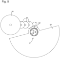
- FIG. 5 shows an automatic winding device usable in a wristwatch equipped with a mechanical part P according to the invention which carries the oscillating mass 50.
- the mechanical part P fixed to the movement, for example screwed onto a board or automatic bridge via the coupling core 40.
- the coupling crown 60 is of the oscillating mass 30 and rotates a rectifier system shown schematically at the Figure 5 by the two well-known rectifier mobiles 52 capable of transforming the rotational movements of the mass whatever their direction into a winding movement in one direction only, for example by means of ratchet wheels.
- the movable rectifiers 52 are followed by a winding gear 54 meshing at its end with the ratchet 56 in order to arm the barrel spring.
Landscapes
- Engineering & Computer Science (AREA)
- General Engineering & Computer Science (AREA)
- Physics & Mathematics (AREA)
- General Physics & Mathematics (AREA)
- Mechanical Engineering (AREA)
- Metallurgy (AREA)
- Manufacturing & Machinery (AREA)
- Rolling Contact Bearings (AREA)
Description
- L'invention concerne une pièce mécanique comprenant un roulement à billes. L'invention trouve une application plus particulièrement dans le domaine de l'horlogerie mais peut également être envisagée pour des applications dans le domaine du médical ou de la micromécanique.
- De manière connue, un roulement à billes comprend une bague externe et une bague interne concentriques définissant ensemble un chemin de roulement pour une pluralité de billes de manière à ce que chaque bille soit en contact avec les dites bagues en une pluralité de points de contact, les billes étant séparées les unes des autres par une cage. Un tel roulement est par exemple décrit dans la
publication EP1520111 . - Afin d'entraîner en rotation l'une des bagues par rapport à l'autre, la paroi externe de la bague externe est généralement dentée pour engrener avec un rouage externe et la bague interne peut être percée d'un évidement afin de permettre sa fixation. Un tel roulement peut être utilisé entre autre pour suspendre une masse oscillante dans un mouvement de montre mécanique.
- Cependant, chaque mouvement horloger possède ses propres moyens de fixation et ses propres rouages, de sorte qu'un roulement est de fait destiné exclusivement à un mouvement horloger hôte pour lequel il a été conçu. Ceci implique donc de fabriquer, stocker et gérer un grand nombre de références de roulements dédiés chacun à un mouvement hôte, ce qui complique et renchérit le processus de fabrication des mouvements.
- Par ailleurs bien que fournissant des propriétés satisfaisantes pour les applications horlogères décrites ci-dessus, les roulements présentent l'inconvénient d'être réalisés généralement en matériaux magnétiques et d'être susceptibles de perturber la marche des mouvements équipés de ces roulements, après avoir été soumis à un champ magnétique.
- Le document
GB754285A - une pluralité de billes (16)
- une bague interne divisée en deux bagues (25, 26), les deux bagues internes étant solidaires l'une de l'autre et comportant des surfaces planes en contact l'une avec l'autre; et
- une bague externe (30) formée d'une seule pièce.
- Dans ce document, les bagues interne externe définissent ensemble un chemin de roulement pour le billes. De plus, la bague interne comprend un évidement central et la pièce mécanique comprend également un noyau de couplage (27) fixé à l'intérieur de l'évidement central de la bague interne, ledit noyau de couplage étant adapté pour coopérer avec un moyen de couplage extérieur (3) correspondant pour permettre la rotation de la bague interne par rapport à la bague externe.
- L'invention vise à améliorer la technique connue, en proposant une solution visant à pallier tout ou partie des inconvénients ou limites des roulements décrits ci-dessus.
- A cet effet, l'invention propose une pièce mécanique horlogère telle que définie dans la revendication indépendante 1 annexée. Des réalisations préférées sont définies dans les revendications dépendantes.
- D'autres caractéristiques et avantages de la présente invention ressortiront plus clairement de la description détaillée qui suit d'exemples de mise en oeuvre de pièce mécaniques selon l'invention. Ces exemples sont donnés à titre purement illustratif et non limitatif et sont à lire en liaison avec les dessins annexés dans lesquels :
- la
figure 1 est une vue en coupe d'un roulement connu de l'art antérieur et utilisable par exemple dans un dispositif de remontage automatique d'une montre bracelet, - les
figures 2-4 sont des vues en coupe de pièces mécaniques selon l'invention telle que revendiquée, et - la
figure 5 est vue de dessus schématique d'un dispositif de remontage automatique utilisable dans une montre bracelet comprenant une pièce mécanique selon un mode de réalisation de l'invention. - Comme dit précédemment, l'invention concerne une pièce mécanique comportant un roulement à billes, ledit roulement comportant :
- une pluralité de billes 1 ;
- une bague interne 2 et une bague externe 3 concentriques, la bague interne et la bague externe définissent ensemble un chemin de roulement pour lesdites billes de manière à ce que chaque bille soit en contact avec lesdites bagues en une pluralité de points de contact.
- La
figure 1 montre un roulement connu de l'art antérieur et utilisable par exemple dans un dispositif de remontage automatique d'une montre bracelet. La bague interne est ici réalisée en deux parties 2a, 2b et une cage 1a est positionnée entre les billes pour maintenir les billes espacées les unes des autres. L'assemblage du roulement se fait en positionnant les billes 1 et la cage 1a dans le chemin de roulement défini par la bague externe et la partie 2a de la - bague interne, la partie 2b restante de la bague interne étant mise en place ensuite pour fermer le roulement.
- Dans une variante, la bague interne est réalisée en une seule partie et la bague externe est réalisée en deux parties.
- Pour limiter les frottements, la bague externe 3, la bague interne 2, et les billes 1 peuvent être réalisées en acier inox ; en variante, les bagues peuvent être réalisées en acier inox et les billes en céramique, par exemple en oxyde de zirconium ; en variante encore, les bagues et les billes peuvent être en céramique.
- Le roulement comprend en outre une paroi externe de la bague externe 3 qui est dentée (dents 4) sur au moins une partie de sa hauteur pour engrener avec un rouage extérieur correspondant. La paroi externe comprend également une portée 31 sur laquelle peut venir s'appuyer la masse oscillante (non représentée) à fixer. La bague interne 2a, 2b est quant à elle percée d'un évidement central 5 adapté pour coopérer avec un moyen de couplage (non représenté) tel qu'un axe ou une vis, ou un rouage.
- Par rapport à un roulement selon la
figure 1 , une pièce mécanique selon l'invention se distingue en ce qu'elle comprend également : - un noyau de couplage 40 fixé à l'intérieur d'un évidement central 21 de la bague interne ; ou
- une couronne de couplage 10 fixée sur une paroi externe de la bague externe et un noyau de couplage 40 fixé à l'intérieur d'un évidement central 21 de la bague interne.
- Ce dernier mode de réalisation est représenté sur les
figures 2 à 5 . - Dans l'exemple illustré, la couronne de couplage 10 est fixée directement sur une paroi externe cylindrique de la bague externe. La couronne de couplage 10 est adaptée pour coopérer avec un moyen de couplage correspondant d'un élément fonctionnel extérieur pour permettre la rotation de la bague externe par rapport à la bague interne. La couronne de couplage selon l'invention vient en lieu et place des dents 4 d'un roulement connu. Il va de soi que selon des variantes de réalisation la couronne 10 peut être fixée sur ou sous la bague extérieure.
- Dans les exemples représentés
fig. 2-5 , la couronne de couplage est une couronne dentée 10 adaptée pour engrener avec un rouage extérieur correspondant. Une telle couronne est bien adaptée notamment pour l'entraînement d'un rouage par une masse oscillante dans un mouvement horloger mécanique. Afin de faciliter la mise en place et le positionnement de la couronne de couplage sur la bague externe, la bague externe peut comprendre une portée 32 sur laquelle vient s'appuyer une portée correspondante d'une paroi interne de la couronne de couplage. Dans l'exemple de lafigure 4 , la couronne de couplage utilisée a un diamètre externe plus grand que le diamètre externe de la couronne de couplage utilisée pour les exemples desfigures 2 et 3 , les éléments principaux du roulement, à savoir les billes 1, la bague interne 2 (2a, 2b) et la bague externe 3 sont par contre les mêmes. - La couronne de couplage et la bague externe sont assemblées par collage, soudage, sertissage ou chassage. Pour des applications où un remplacement de la couronne doit être envisagé au cours de la durée d'utilisation de la pièce mécanique, une fixation amovible par chassage est préférée.
- Pour une utilisation en environnement magnétique fort, dans les exemples mis en oeuvre, la couronne de couplage 10 est réalisée en un matériau amagnétique, ici un alliage Cuivre- Béryllium typiquement un alliage CuBe2Pb ou CuBe2.
- D'autres matériaux amagnétiques peuvent être envisagés, des matériaux choisi parmi le groupe comprenant un acier du type austénitique, de préférence inoxydable, un alliage de cobalt du type austénitique, un alliage de nickel du type austénitique, un alliage de titane amagnétique, un alliage d'aluminium amagnétique, un laiton (Cu-Zn) ou un laiton spécial (Cu-Zn avec Al et/ou Si et/ou Mn), un bronze (Cu-Sn), un bronze à l'aluminium, un cuivre-aluminium (comprenant optionnellement Ni et/ou Fe), un cuivre-nickel, un Maillechort (Cu-Ni-Zn), un cuivre-nickel-étain, un cuivre-nickel-silicium, un cuivre-nickel-phosphore, un cuivre-titane, les proportions des différents éléments des alliages étant choisies pour leur conférer des propriétés amagnétiques ainsi qu'une bonne usinabilité.
- Par exemple, l'acier austénitique est un acier austénitique inox HIS (High Interstitial Steels), tel que l'acier Cr-Mn-N P2000 de Energietechnik Essen GmbH.
- L'alliage de cobalt du type austénitique peut comprendre au moins 39% de cobalt, typiquement un alliage connu sous le nom « Phynox » ou la désignation DIN K13C20N16Fe15D7 ayant typiquement 39% de Co, 19% de Cr, 15% de Ni et 6% de Mo, 1.5% de Mn, 18% de Fe et le soldes d'additifs.
- L'alliage de nickel de type austénitique peut comprendre au moins 33% de nickel typiquement un alliage connu sous la désignation MP35N® ayant typiquement 35% de Ni 20% de Cr, 10% de Mo, 33% de Co et le solde d'additifs.
- L'alliage de titane comprend de préférence au moins 85% de titane.
- Les laitons peuvent comprendre les alliages CuZn39Pb3, CuZn37Pb2, ou CuZn37.
- Les laitons spéciaux peuvent comprendre les alliages CuZn37Mn3Al2PbSi, CuZn23Al3Co ou CuZn23Al6Mn4Fe3Pb.
- Les Maillechort peuvent comprendre les alliages CuNi25Zn11Pb1Mn, CuNi7Zn39Pb3Mn2 ou CuNi18Zn19Pb1.
- Les bronzes peuvent comprendre les alliages CuSn9 ou CuSn6.
- Les bronzes à l'aluminium peuvent comprendre les alliages CuAl9 ou CuAl9Fe5Ni5.
- Les alliages cuivre-nickel peuvent comprendre l'alliage CuNi30.
- Les alliages cuivre-nickel-étain peuvent comprendre les alliages CuNi15Sn8, CuNi9Sn6 ou CuNi7.5Sn5 (commercialisé par exemple sous la dénomination Declafor).
- Les alliages cuivre-titane peuvent comprendre l'alliage CuTi3Fe.
- Les alliages cuivre-nickel-silicium peuvent comprendre l'alliage CuNi3Si.
- Les alliages cuivre-nickel-phosphore peuvent comprendre l'alliage CuNi1P.
- Les valeurs de composition sont indiquées en pourcentage massique. Les éléments sans indication de valeur de composition sont soit le reste (majoritaire) soit des éléments pour lesquels le pourcentage dans la composition est inférieur à 1% en poids.
- L'alliage de cuivre amagnétique peut être également un alliage ayant pour composition massique entre 14.5% et 15.5% de Ni, entre 7.5% et 8.5% de Sn, au maximum 0.02% de Pb et le reste de Cu. Un tel alliage est commercialisé sous la marque Toughmet® par la société Materion.
- Bien évidemment, d'autres alliages amagnétiques sont envisageables dès lors que la proportion de leurs constituants leur confère des propriétés amagnétiques ainsi qu'une bonne usinabilité.
- La bague interne 2 comprend un évidement central 21 s'étendant selon un axe de la bague interne. L'évidement central 21 est concentrique à la bague interne et le noyau de couplage 40 est fixé à l'intérieur de l'évidement 21. Le noyau de couplage 40 est adapté pour coopérer avec un moyen de couplage correspondant d'un élément fonctionnel extérieur pour permettre la rotation de la bague interne 2 par rapport à la bague externe 3.
- A cet effet, dans l'exemple des
figures 2 et 4 , le noyau de couplage 40 est percé d'un évidement central 41 concentrique à la bague interne 2 ; une paroi de l'évidement central 41 est dentée pour engrener avec un rouage externe. - Selon un autre mode de réalisation, dans l'exemple de la
figure 3 , deux évidements 42, 43 filetés sont prévus pour une fixation par deux vis formant un moyen de couplage (fixation ici) externe. En variante, un unique évidement fileté en position centrale peut aussi être envisagé. - Le noyau de couplage 40 et la bague interne sont assemblés par collage, soudage, sertissage ou chassage. Pour certaines applications, une fixation amovible par chassage est préférable.
- Le noyau de couplage 40 est réalisé en un matériau amagnétique pour limiter sa sensibilité aux champs magnétiques. A titre d'exemple, le noyau peut être réalisé ici comme la couronne de couplage 10 en un alliage Cuivre- Béryllium typiquement un alliage CuBe2Pb ou CuBe2. Les autres matériaux appartenant à la liste de matériaux mentionnés en liaison avec la couronne de couplage 10 conviennent également.
- Pour des raisons esthétiques, la couronne de couplage 10 et/ou le noyau de couplage 40 peuvent être recouverts d'un revêtement modifiant un aspect de leurs surfaces extérieures par exemple par des traitements de dorage, nickelage ou rhodiage ou tout autre dépôt PVD.
- La
figure 5 montre un dispositif de remontage automatique utilisable dans une montre-bracelet équipée d'une pièce mécanique P selon l'invention qui porte la masse oscillante 50. La pièce mécanique P fixée sur le mouvement, par exemple vissé sur une planche ou pont d'automatique par l'intermédiaire du noyau de couplage 40. - La couronne de couplage 60 est de la masse oscillante 30 et entraîne en rotation un système redresseur représenté schématiquement à la
figure 5 par les deux mobiles redresseurs 52 bien connues et aptes à transformer les mouvements de rotation de la masse quel que soit leur sens en un mouvement de remontage dans un seul sens, par exemple au moyen de roues à cliquet. Les mobiles redresseurs 52 sont suivis par un rouage de remontage 54 engrenant à son extrémité avec le rochet 56 afin d'armer le ressort de barillet. -
- 1
- billes
- 1a :
- cage
- 2
- bague interne
- 2a, 2b :
- deux parties de la bague interne
- 21
- évidement
- 3
- bague externe
- 31
- portée
- 32
- portée
- 4
- dents
- 5
- évidement central
- 10
- couronne de couplage
- 40
- noyau de couplage
- 41
- évidement central
- 42, 43
- évidements
- 50
- masse oscillante
- 52
- mobiles inverseurs
- 54
- rouage de remontage
- 56
- rochet
Claims (10)
- Pièce mécanique horlogère comportant un roulement à billes, ledit roulement comportant :• une pluralité de billes (1) ;• une bague interne (2) et une bague externe (3) concentriques, la bague interne et la bague externe définissant ensemble un chemin de roulement pour lesdites billes de manière à ce que chaque bille soit en contact avec lesdites bagues en une pluralité de points de contact, pièce mécanique dans laquelle la bague interne (2) comprend deux bagues (2a, 2b), ces deux bagues étant solidaires l'une de l'autre et comportant des surfaces cylindriques en contact l'une avec l'autre, alors que la bague externe (3) est formée d'une seule pièce, la bague interne (2) comprenant un évidement central (21) s'étendant selon un axe de la bague interne, la pièce mécanique comprenant également un noyau de couplage (40) fixé à l'intérieur de l'évidement central de la bague interne, ledit noyau de couplage étant adapté pour coopérer avec un moyen de couplage extérieur correspondant pour permettre la rotation de la bague interne par rapport à la bague externe, le noyau de couplage étant réalisé en un matériau amagnétique, et comprenant:• au moins un évidement fileté (42, 43) adapté pour recevoir un moyen de fixation d'un élément fonctionnel extérieur, ou• un évidement central (41) concentrique à la bague interne, une paroi de l'évidement central étant dentée pour engrener avec une denture correspondante d'un rouage externe.
- Pièce mécanique horlogère selon la revendication 1 dans laquelle le noyau de couplage et la bague interne sont assemblés par collage, soudage, sertissage ou chassage.
- Pièce mécanique horlogère selon la revendication 1 ou 2 caractérisée en ce qu'elle comprend également une couronne de couplage (10) fixée sur une paroi externe de la bague externe, ladite couronne de couplage étant adaptée pour coopérer avec un moyen de couplage correspondant d'un élément fonctionnel extérieur.
- Pièce mécanique horlogère selon la revendication 3 caractérisée en ce que la couronne de couplage est réalisée en un matériau amagnétique.
- Pièce mécanique horlogère selon l'une des revendications précédentes, caractérisée en ce que la couronne de couplage et/ou le noyau de couplage sont réalisés en un matériau choisi parmi le groupe comprenant un acier du type austénitique, un alliage de cobalt du type austénitique, un alliage de nickel du type austénitique, un alliage de titane, un alliage d'aluminium, un laiton à base de cuivre et de zinc, un cuivre-béryllium, un Maillechort, un bronze, un bronze à l'aluminium, un cuivre-aluminium, un cuivre-nickel, un cuivre-nickel-étain, un cuivre-nickel-silicium, un cuivre-nickel-phosphore, un cuivre-titane, le téflon afin de limiter sa sensibilité aux champs magnétiques.
- Pièce mécanique horlogère selon l'une des revendications précédentes caractérisée en ce que la couronne de couplage et/ou le noyau de couplage sont recouverts d'un revêtement modifiant un aspect d'une surface extérieure de la couronne de couplage et/ou du noyau de couplage.
- Pièce mécanique horlogère selon la revendication 5 caractérisée en ce que la couronne de couplage et/ou le noyau de couplage sont réalisés en aluminium anodisé.
- Pièce mécanique horlogère selon l'une des revendications précédentes caractérisée en ce que la bague externe et la bague interne sont réalisées en inox.
- Pièce mécanique horlogère selon la revendication 8 caractérisée en ce que les billes sont réalisées en acier ou en céramique, de préférence en oxyde de zirconium.
- Pièce mécanique horlogère selon l'une quelconque des revendications précédentes caractérisée en ce qu'elle porte une masse oscillante dans un dispositif de remontage automatique d'un mouvement d'horlogerie.
Applications Claiming Priority (2)
| Application Number | Priority Date | Filing Date | Title |
|---|---|---|---|
| EP17177523.2A EP3418594A1 (fr) | 2017-06-22 | 2017-06-22 | Pièce mécanique modulaire |
| PCT/EP2018/065715 WO2018234125A1 (fr) | 2017-06-22 | 2018-06-13 | Piece mecanique modulaire |
Publications (2)
| Publication Number | Publication Date |
|---|---|
| EP3642496A1 EP3642496A1 (fr) | 2020-04-29 |
| EP3642496B1 true EP3642496B1 (fr) | 2023-10-11 |
Family
ID=59152738
Family Applications (2)
| Application Number | Title | Priority Date | Filing Date |
|---|---|---|---|
| EP17177523.2A Withdrawn EP3418594A1 (fr) | 2017-06-22 | 2017-06-22 | Pièce mécanique modulaire |
| EP18729172.9A Active EP3642496B1 (fr) | 2017-06-22 | 2018-06-13 | Piece mecanique modulaire |
Family Applications Before (1)
| Application Number | Title | Priority Date | Filing Date |
|---|---|---|---|
| EP17177523.2A Withdrawn EP3418594A1 (fr) | 2017-06-22 | 2017-06-22 | Pièce mécanique modulaire |
Country Status (4)
| Country | Link |
|---|---|
| EP (2) | EP3418594A1 (fr) |
| CN (1) | CN211778518U (fr) |
| CH (1) | CH713937A2 (fr) |
| WO (1) | WO2018234125A1 (fr) |
Families Citing this family (1)
| Publication number | Priority date | Publication date | Assignee | Title |
|---|---|---|---|---|
| FR3124834B1 (fr) * | 2021-07-01 | 2023-06-30 | Mps Micro Prec Systems Ag | Roulement pour mécanisme horloger ou médical et son procédé de fabrication |
Family Cites Families (4)
| Publication number | Priority date | Publication date | Assignee | Title |
|---|---|---|---|---|
| GB754285A (en) * | 1954-07-14 | 1956-08-08 | Fischer Bearings Company Ltd | Improvements in bearings for self-winding watch mechanisms |
| CH682871B5 (fr) * | 1992-06-06 | 1994-06-15 | Piguet Frederic Sa | Mouvement de montre extra-plat. |
| WO2003098063A1 (fr) | 2002-05-15 | 2003-11-27 | Mps Micro Precision Systems Ag | Roulement |
| CH707859A1 (fr) * | 2013-04-02 | 2014-10-15 | Mps Micro Prec Systems Ag | Pièce mécanique à roulement à billes pour applications horlogères ou microtechniques. |
-
2017
- 2017-06-22 EP EP17177523.2A patent/EP3418594A1/fr not_active Withdrawn
- 2017-06-22 CH CH00822/17A patent/CH713937A2/fr unknown
-
2018
- 2018-06-13 EP EP18729172.9A patent/EP3642496B1/fr active Active
- 2018-06-13 CN CN201890000960.XU patent/CN211778518U/zh active Active
- 2018-06-13 WO PCT/EP2018/065715 patent/WO2018234125A1/fr unknown
Also Published As
| Publication number | Publication date |
|---|---|
| CH713937A2 (fr) | 2018-12-28 |
| EP3642496A1 (fr) | 2020-04-29 |
| CN211778518U (zh) | 2020-10-27 |
| EP3418594A1 (fr) | 2018-12-26 |
| WO2018234125A1 (fr) | 2018-12-27 |
Similar Documents
| Publication | Publication Date | Title |
|---|---|---|
| EP1918789B1 (fr) | Masse oscillante pour recharger la source d'énergie d'un instrument portable | |
| EP2212749B1 (fr) | Organe moteur a ressorts pour mouvement d'horlogerie | |
| EP2350745B1 (fr) | Organe moteur pour mouvement horloger | |
| EP1580624A2 (fr) | Mobile destiné à venir en contact avec un autre élément mobile ou fixe | |
| EP3642496B1 (fr) | Piece mecanique modulaire | |
| EP2110719B1 (fr) | Amortisseur de choc pour masse oscillante | |
| EP1513029B1 (fr) | Virole d'horlogerie | |
| EP1445668A1 (fr) | Masse oscillante | |
| EP1515200A1 (fr) | Spiral d'horlogerie | |
| EP3252542A1 (fr) | Pièce de fixation d'un ressort-spiral horloger | |
| EP2919077B1 (fr) | Dispositif d'entraînement d'un indicateur analogique, notamment d'un anneau des quantiemes | |
| EP1698949A1 (fr) | Dispositif de remontage automatique pour recharger la source d'énergie d'un instrument portable | |
| CH697381B1 (fr) | Mécanisme comprenant un premier mobile en contact ou destiné à venir en contact avec un deuxième élément. | |
| EP3309624A1 (fr) | Procede d'assemblage de composants horlogers | |
| EP3401740B1 (fr) | Composant horloger pour chassage sans bavure | |
| EP3707563B1 (fr) | Organe moteur d'horlogerie | |
| EP0770937B1 (fr) | Pièce d'horlogerie comportant une lunette tournante | |
| EP2798414B1 (fr) | Ressort pour mouvement horloger | |
| EP2813900A2 (fr) | Protection de composant de structure d'horlogerie | |
| EP3051364B1 (fr) | Système de transmission mécanique par adhérence pour rouage horloger. | |
| EP3499317A1 (fr) | Mobile de calendrier horloger | |
| CH715376B1 (fr) | Mouvement d'horlogerie comprenant un roulement mécanique amagnétique, et montre comportant un tel roulement. | |
| EP3714336B1 (fr) | Maintien d'un mobile portant un disque d'affichage | |
| CH713607A2 (fr) | Système de barillets pour pièce d'horlogerie mécanique. | |
| EP3252541A1 (fr) | Pièce de fixation d'un ressort-spiral horloger |
Legal Events
| Date | Code | Title | Description |
|---|---|---|---|
| STAA | Information on the status of an ep patent application or granted ep patent |
Free format text: STATUS: UNKNOWN |
|
| STAA | Information on the status of an ep patent application or granted ep patent |
Free format text: STATUS: THE INTERNATIONAL PUBLICATION HAS BEEN MADE |
|
| PUAI | Public reference made under article 153(3) epc to a published international application that has entered the european phase |
Free format text: ORIGINAL CODE: 0009012 |
|
| STAA | Information on the status of an ep patent application or granted ep patent |
Free format text: STATUS: REQUEST FOR EXAMINATION WAS MADE |
|
| 17P | Request for examination filed |
Effective date: 20200122 |
|
| AK | Designated contracting states |
Kind code of ref document: A1 Designated state(s): AL AT BE BG CH CY CZ DE DK EE ES FI FR GB GR HR HU IE IS IT LI LT LU LV MC MK MT NL NO PL PT RO RS SE SI SK SM TR |
|
| AX | Request for extension of the european patent |
Extension state: BA ME |
|
| DAV | Request for validation of the european patent (deleted) | ||
| DAX | Request for extension of the european patent (deleted) | ||
| STAA | Information on the status of an ep patent application or granted ep patent |
Free format text: STATUS: EXAMINATION IS IN PROGRESS |
|
| 17Q | First examination report despatched |
Effective date: 20211026 |
|
| REG | Reference to a national code |
Ref country code: DE Ref legal event code: R079 Ref document number: 602018059135 Country of ref document: DE Free format text: PREVIOUS MAIN CLASS: F16C0019160000 Ipc: G04B0031012000 Ref country code: DE |
|
| GRAP | Despatch of communication of intention to grant a patent |
Free format text: ORIGINAL CODE: EPIDOSNIGR1 |
|
| STAA | Information on the status of an ep patent application or granted ep patent |
Free format text: STATUS: GRANT OF PATENT IS INTENDED |
|
| RIC1 | Information provided on ipc code assigned before grant |
Ipc: G04B 5/18 20060101ALI20230623BHEP Ipc: G04B 31/004 20060101ALI20230623BHEP Ipc: F16C 33/58 20060101ALI20230623BHEP Ipc: F16C 19/16 20060101ALI20230623BHEP Ipc: G04B 31/012 20060101AFI20230623BHEP |
|
| INTG | Intention to grant announced |
Effective date: 20230713 |
|
| P01 | Opt-out of the competence of the unified patent court (upc) registered |
Effective date: 20230701 |
|
| RIN1 | Information on inventor provided before grant (corrected) |
Inventor name: CONUS, THIERRY Inventor name: BERDAT, XAVIER Inventor name: COURVOISIER, RAPHAEL |
|
| GRAS | Grant fee paid |
Free format text: ORIGINAL CODE: EPIDOSNIGR3 |
|
| GRAA | (expected) grant |
Free format text: ORIGINAL CODE: 0009210 |
|
| STAA | Information on the status of an ep patent application or granted ep patent |
Free format text: STATUS: THE PATENT HAS BEEN GRANTED |
|
| AK | Designated contracting states |
Kind code of ref document: B1 Designated state(s): AL AT BE BG CH CY CZ DE DK EE ES FI FR GB GR HR HU IE IS IT LI LT LU LV MC MK MT NL NO PL PT RO RS SE SI SK SM TR |
|
| REG | Reference to a national code |
Ref country code: GB Ref legal event code: FG4D Free format text: NOT ENGLISH |
|
| REG | Reference to a national code |
Ref country code: CH Ref legal event code: EP |
|
| REG | Reference to a national code |
Ref country code: DE Ref legal event code: R096 Ref document number: 602018059135 Country of ref document: DE |
|
| REG | Reference to a national code |
Ref country code: IE Ref legal event code: FG4D Free format text: LANGUAGE OF EP DOCUMENT: FRENCH |
|
| REG | Reference to a national code |
Ref country code: LT Ref legal event code: MG9D |
|
| REG | Reference to a national code |
Ref country code: NL Ref legal event code: MP Effective date: 20231011 |
|
| REG | Reference to a national code |
Ref country code: AT Ref legal event code: MK05 Ref document number: 1620826 Country of ref document: AT Kind code of ref document: T Effective date: 20231011 |
|
| PG25 | Lapsed in a contracting state [announced via postgrant information from national office to epo] |
Ref country code: NL Free format text: LAPSE BECAUSE OF FAILURE TO SUBMIT A TRANSLATION OF THE DESCRIPTION OR TO PAY THE FEE WITHIN THE PRESCRIBED TIME-LIMIT Effective date: 20231011 |
|
| PG25 | Lapsed in a contracting state [announced via postgrant information from national office to epo] |
Ref country code: GR Free format text: LAPSE BECAUSE OF FAILURE TO SUBMIT A TRANSLATION OF THE DESCRIPTION OR TO PAY THE FEE WITHIN THE PRESCRIBED TIME-LIMIT Effective date: 20240112 |
|
| PG25 | Lapsed in a contracting state [announced via postgrant information from national office to epo] |
Ref country code: IS Free format text: LAPSE BECAUSE OF FAILURE TO SUBMIT A TRANSLATION OF THE DESCRIPTION OR TO PAY THE FEE WITHIN THE PRESCRIBED TIME-LIMIT Effective date: 20240211 |
|
| PG25 | Lapsed in a contracting state [announced via postgrant information from national office to epo] |
Ref country code: LT Free format text: LAPSE BECAUSE OF FAILURE TO SUBMIT A TRANSLATION OF THE DESCRIPTION OR TO PAY THE FEE WITHIN THE PRESCRIBED TIME-LIMIT Effective date: 20231011 |
|
| PG25 | Lapsed in a contracting state [announced via postgrant information from national office to epo] |
Ref country code: AT Free format text: LAPSE BECAUSE OF FAILURE TO SUBMIT A TRANSLATION OF THE DESCRIPTION OR TO PAY THE FEE WITHIN THE PRESCRIBED TIME-LIMIT Effective date: 20231011 |
|
| PG25 | Lapsed in a contracting state [announced via postgrant information from national office to epo] |
Ref country code: ES Free format text: LAPSE BECAUSE OF FAILURE TO SUBMIT A TRANSLATION OF THE DESCRIPTION OR TO PAY THE FEE WITHIN THE PRESCRIBED TIME-LIMIT Effective date: 20231011 |
|
| PG25 | Lapsed in a contracting state [announced via postgrant information from national office to epo] |
Ref country code: LT Free format text: LAPSE BECAUSE OF FAILURE TO SUBMIT A TRANSLATION OF THE DESCRIPTION OR TO PAY THE FEE WITHIN THE PRESCRIBED TIME-LIMIT Effective date: 20231011 Ref country code: IS Free format text: LAPSE BECAUSE OF FAILURE TO SUBMIT A TRANSLATION OF THE DESCRIPTION OR TO PAY THE FEE WITHIN THE PRESCRIBED TIME-LIMIT Effective date: 20240211 Ref country code: GR Free format text: LAPSE BECAUSE OF FAILURE TO SUBMIT A TRANSLATION OF THE DESCRIPTION OR TO PAY THE FEE WITHIN THE PRESCRIBED TIME-LIMIT Effective date: 20240112 Ref country code: ES Free format text: LAPSE BECAUSE OF FAILURE TO SUBMIT A TRANSLATION OF THE DESCRIPTION OR TO PAY THE FEE WITHIN THE PRESCRIBED TIME-LIMIT Effective date: 20231011 Ref country code: BG Free format text: LAPSE BECAUSE OF FAILURE TO SUBMIT A TRANSLATION OF THE DESCRIPTION OR TO PAY THE FEE WITHIN THE PRESCRIBED TIME-LIMIT Effective date: 20240111 Ref country code: AT Free format text: LAPSE BECAUSE OF FAILURE TO SUBMIT A TRANSLATION OF THE DESCRIPTION OR TO PAY THE FEE WITHIN THE PRESCRIBED TIME-LIMIT Effective date: 20231011 Ref country code: PT Free format text: LAPSE BECAUSE OF FAILURE TO SUBMIT A TRANSLATION OF THE DESCRIPTION OR TO PAY THE FEE WITHIN THE PRESCRIBED TIME-LIMIT Effective date: 20240212 |